

Page 1
MODEL DPF50
3 1/2 DIGIT MINI-SIZE PROCESS METER (DPF56)
WITH ISOLATED EXCITATION (DPF57)
SPECIFICATIONS
Analog Input
Range 4-20 mA 0-0.2 V 1-5 V 0-10 V 0-100 V
Input resistance 13 Ω 1 MΩ 1 MΩ 1 MΩ 1 MΩ
Bias current 50 pA 50 pA 10 pA 5 pA 1 pA
Maximum input 55 mA 250 Vp 250 Vp 250 Vp 250 Vp
Noise Rejection
NMR, sig hi to sig lo 56 dB, 50/60 Hz
CMR, sig lo to pwr gnd 120 dB, DC to 60 Hz
CMV, sig lo to pwr gnd 1500 Vp per HV test; 354 Vp per
IEC spacing
Accuracy at 25°C / Display
Maximum error ±0.05% of reading ±1 count
Display range ±1999
Span adjustment 0-2000 counts
Span tempco ±0.02% of reading/°C
Zero adjustment -1500 to +500 counts with zero input
Zero tempco ±0.01% of offset ±0.2 counts/°C
Full-scale step response 1 second
Warmup 30 minutes
Reading rate 2.5 / second
Overrange indication Three least-significant digits blank
Power Options
Input power 24, 100, 115 or 230 Vac ±15%,
49-63 Hz, DPF56 and DPF57
+5 or 7-32 Vdc, non-isolated for
DPF56 option only
Transmitter Excitation Supply (DPF57 ONLY)
Output voltage User Selectable for 10 or 24 Vdc
Output current, max 30 mA @ 10 V, 20 mA @ 24 V
Line regulation ±0.01% / V of ac power
Load regulation ±0.5%
Tempco ±0.02% / °C
Ripple at 50/60 Hz ±0.01%
Environmental
Operating temperature 32 to 140°F
Storage temperature -40 to 185°F
Relative humidity 95% at 104°F (non-condensing)
Mechanical
Bezel 01.89” x 3.78" (48 x 96 mm)
Depth Behind the Bezel 4.32" (110 mm) w/ connectors
Panel Cutout 1/8 DIN 01.72" H x 3.62" W (45 x 92 mm)
Weight 8 ounces (227 grams)
Case Material 94V-1 UL-rated thermoplastic
Panel Thickness Minimum: 0.03” (0.76 mm)
Maximum: 0.25” (6.35 mm)
OMEGA ENGINEERING, INC. warrants this unit to be free of defects in materials and workmanship for a period of
13 months from date of purchase. OMEGA Warranty adds an additional one (1) month grace period to the normal one (1) year product warranty to cover handling and shipping time. This ensures that OMEGA’s customers
receive maximum coverage on each product.
If the unit should malfunction, it must be returned to the factory for evaluation. OMEGA’s Customer Service
Department will issue an Authorized Return (AR) number immediately upon phone or written request. Upon examination by OMEGA, if the unit is found to be defective it will be repaired or replaced at no charge. OMEGA’sWAR-
RANTY does not apply to defects resulting from any action of the purchaser, including but not limited to mishandling, improper interfacing, operation outside of design limits, improper repair, or unauthorized modification. This
WARRANTY is VOID if the unit shows evidence of having been tampered with or shows evidence of being damaged
as a result of excessive corrosion; or current, heat, moisture or vibration; improper specification; misapplication;
misuse or other operating conditions outside of OMEGA’s
control. Components which wear are not warranted, includ-
ing but not limited to contact points, fuses, and triacs.
OMEGA is pleased to offer suggestions on the use of its various products. However,
OMEGA neither assumes responsibility for any omissions or errors nor assumes liability for any damages
that result from the use of its products in accordance with information provided by OMEGA, either verbal
or written. OMEGA warrants only that the parts manufactured by it will be as specified and free of defects.
OMEGA MAKES NO OTHER WARRANTIES OR REPRESENTATIONS OF ANY KIND WHATSOEVER,
EXPRESSED OR IMPLIED, EXCEPT THAT OF TITLE, AND ALL IMPLIED WARRANTIES INCLUDING ANY WARRANTY OF MERCHANTABILITY AND FITNESS FOR A PARTICULAR PURPOSE ARE HEREBY DISCLAIMED.
LIMITATION OF LIABILITY: The remedies of purchaser set forth herein are exclusive and the total liability of
OMEGA with respect to this order, whether based on contract, warranty, negligence, indemnification, strict
liability or otherwise, shall not exceed the purchase price of the component upon which liability is based. In
no event shall OMEGA be liable for consequential, incidental or special damages.
CONDITIONS: Equipment sold by OMEGA is not intended to be used, nor shall it be used: (1) as a “Basic
Component” under 10 CFR 21 (NRC), used in or with any nuclear installation or activity; or (2) in medical applications or used on humans. Should any Product(s) be used in or with any nuclear installation or activity, medical application, used on humans, or misused in any way, OMEGA assumes no responsibility as set forth in our basic WARRANTY/DISCLAIMER language, and additionally, purchaser will indemnify OMEGAand hold OMEGA harmless from
any liability or damage whatsoever arising out of the use of the Product(s) in such a manner.
Direct all warranty and repair requests/inquiries to the OMEGA Customer Service Department. BEFORE
RETURNING ANY PRODUCT(S) TO OMEGA, PURCHASER MUST OBTAIN AN AUTHORIZED RETURN (AR)
NUMBER FROM OMEGA’S CUSTOMER SERVICE DEPARTMENT (IN ORDER TO AVOID PROCESSING DELAYS).
The assigned AR number should then be marked on the outside of the return package and on any
correspondence.
The purchaser is responsible for shipping charges, freight, insurance and proper packaging to prevent breakage
in transit.
FOR
WARRANTY RETURNS, please have the following information available BEFORE
contacting OMEGA:
1. P.O. number under which the product was
PURCHASED,
2. Model and serial number of the product under
warranty, and
3. Repair instructions and/or specific problems
relative to the product.
FOR NON-WARRANTY REPAIRS,
consult OMEGA for
current repair charges. Have the following information
available BEFORE contacting OMEGA:
1. P.O. number to cover the COST of the repair,
2. Model and serial number of product, and
3. Repair instructions and/or specific problems
relative to the product.
OMEGA’s policy is to make running changes, not model changes, whenever an improvement is possible. This
affords our customers the latest in technology and engineering.
OMEGA is a registered trademark of OMEGA ENGINEERING, INC.
© Copyright 2007 OMEGA ENGINEERING, INC. All rights reserved. This document may not be copied,
photocopied, reproduced, translated, or reduced to any electronic medium or machine-readable form, in whole
or in part, without prior written consent of OMEGA ENGINEERING, INC.
RETURN REQUESTS / INQUIRIES
WARRANTY/DISCLAIMER
It is our policy to comply with all applicable safety and EMC/EMI regulations worldwide. We are constantly pursuing
certification of our products to the European New Approach Directives. We will add the CE mark to every appropriate device
upon certification.
This device is marked with the international caution symbol. It is important to read the Setup Guide before installing or
commissioning this device as it contains important information relating to safety and EMC.
M1515/0707 11430ML-98B
USA
MADE IN
OMEGAnet¤ On-Line Service
www.omega.com
Servicing North America:
USA: One Omega Drive, P.O. Box 4047
ISO 9001 Certified Stamford CT 06907-0047
TEL: (203) 359-1660 FAX: (203) 359-7700
e-mail: info@omega.com
Canada: 976 Bergar
Laval (Quebec) H7L 5A1
TEL: (514) 856-6928 FAX: (514) 856-6886
e-mail: info@omega.ca
For immediate technical or application assistance:
USA and Canada: Sales Service: 1-800-826-6342 / 1-800-TC-OMEGA
Customer Service: 1-800-622-2378 / 1-800-622-BEST
Engineering Service: 1-800-872-9436 / 1-800-USA-WHEN
Mexico and TEL: (001) 203-359-7803 FAX: (001) 203-359-7807
Latin American: e-mail: espanol@omega.com
Benelux: TEL: +31 20 3472121 FAX: +31 20 6434643
Toll Free in Benelux: 0800 0993344
e-mail: sales@omegaeng.nl
Czech Republic: Frystatska 184, 733 01 Karviná
TEL: +420 59 6311899 FAX: +420 59 6311114
e-mail: info@omegashop.cz
France: TEL: +33 1 61 37 29 00 FAX: +33 1 30 57 54 27
Toll Free in France: 0800 466 342
e-mail: sales@omega.fr
Germany/Austria: Daimlerstrasse 26, D-75392 Deckenpfronn, Germany
TEL: +49 7056 9398-0 F
Toll Free in Germany: 0800 639 7678
e-mail: info@omega.de
United Kingdom: One Omega Drive
ISO 9001 Certified River Bend Technology Centre
Northbank, Irlam Manchester M44 5BD United Kingdom
TEL: +44 161 777 6611 FAX: +44 161 777 6622
Toll Free in England: 0800 488 488
e-mail: sales@omega.co.uk
®
®
Internet e-mail
info@omega.com
®
®
Servicing Europe:
AX: +49 7056 9398-29
®
Page 2
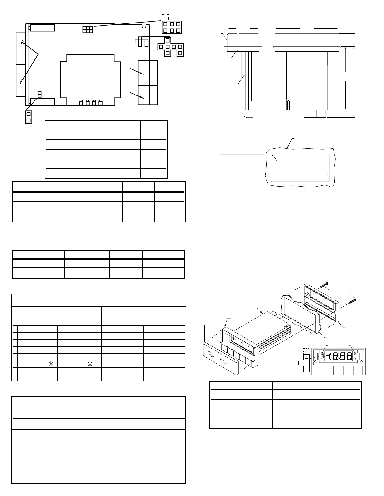
BACKPLATE
SCREWS
METER
BEZEL
LENS
PANEL WITH
1/8 DIN CUTOUT
1/8 DIN PANEL CUTOUT
0.25 [6.4] MAX
0.03 [0.8] MIN
PANEL THICKNESS
3.622 +0.032/-.000
[92.00 +0.81/-0.00]
1.772 +0.024/-.000
[45.0 +0.61/-0.00]
0.06
[1.5]
4PLCS
R
DIMENSIONS
INSTALLATION
1. Remove the 2 phillips screws from behind the display (you don't
have to go inside the meter) holding the rectangular backplate to
the meter. Remove the backplate and set aside.
2. Cut or punch a hole in the panel where you want the meter to
go. The panel can be as thick as 0.25" (6.4mm) to as thin as
0.03" (0.8mm).
3. Insert the meter into the panel cutout.
4. From the rear of the panel, slide the backplate over the case
(smooth side out).
5. Install the 2 phillips screws to secure the meter in 1/8 DIN
mount. Center the meter in hole prior to tightening screws.
CALIBRATION
1. Apply the minimum current or voltage to the signal input.
Adjust the zero pot for the minimum display reading ±1 count.
2. Apply the maximum current or voltage to the signal input.
Adjust the span pot for the maximum display reading ±1 count.
3. Repeat steps 1 and 2 until ±1 count desired reading. Reinstall
the lens.
Decimal Point S1
1.999 A
19.99 B
199.9 C
1999 Store jumper above A
POWER AND SIGNAL INPUT
~ AC POWER ≠ DC POWER
DDPPFF5577 DDPPFF5566 DDPPFF5577 DDPPFF5566
1 SIG HI (+S) SIG HI (+S) SIG HI (+S) SIG HI (+S)
2 SIG LO (-S) SIG LO (-S) SIG LO (-S) SIG LO (-S)
3 + Exc Hold + Exc Hold
4 - Exc Digital Return - Exc Digital Return
5 Earth GND Earth GND -DC (-) -DC (-)
6 Neutral (N) Neutral (N) +DC (+) -DC (+)
7 Line (L) Line (L) N/C N/C
S3
S2
A
A
A
B
B
CCD
DE
S2
S3
S4
S4
SIGNAL
DISPLAY
SPAN
ZERO
POWER
W1W2 W3
1
2
3
4
5
6
7
RANGE SELECTION
CURRENT / VOLTAGE INPUT S3
4-20 mA D, E
0-0.2 V dc E
1-5 V dc A
0-10 V dc B
0-100 V dc C
Voltage operation was configured per customer order.
115 and 230 Vac operation use the same transformer and may be
reversed with simple wiring installation.
TRANSFORMER # AC VOLTAGE INSTALL REMOVE
48131 115 W1, W3 W2
48131 230 W2 W1, W3
ELECTRICAL CONNECTIONS
AVAILABLE MODELS
EXCITATION VOLTAGE (DPF57 only) S2 S4
10 V, standard internal reference B, D A
24 V, standard internal reference B, D 10 V, excitation reference A, C A
DESCRIPTION PART #
Field selectable for 4-20 mA, 0-199.9 mV DPF56
1-5 V dc, 0-10 V dc, 0-100 V dc input
DPF56 with sensor excitation output DPF57
OPTIONS PART #
230 V ac power input Add suffix "-230"
100 V ac power input Add suffix "-100VAC"
24 V ac power input Add suffix "-24VAC"
5 V dc power input (DPF56 only) Add suffix "-5V"
7-32 V dc power input (DPF56 only) Add suffix "-7/32V"
Green LED display (instead of Red) Add suffix "-GR"
BEZEL
BACKPLATE
CASE
1.89
[48.0]
3.78
[96.0]
0.76 [19.3]
3.76
[95.5]
4.32
[109.7]
MAX
TOP VIEWSIDE VIEW
ZERO SPAN
A
B
C
S1
 Loading...