

Page 1
DP21 SERIES
MICROPROCESSOR-BASED
DIGITAL INDICATOR
INSTRUCTION MANUAL
Thank you for purchasing the Omega DP21 Series.
Please check that the delivered product is the correct item you orderd.
Please do not begin operating this product until you have read
this instruction manual thoroughly and understand its contents.
"Notice"
Please ensure that this instruction manual is given to the final user of
the instrument.
Preface
This instruction manual is meant for those who will be involved in the
wiring, installation, operation and routine maintenance of the DP21
series.
This manual describes the care, installation, wiring, function, and
proper procedures for the operation of DP21 series. Keep this manual
at the work site during operation of the DP21 series. While using this
instrument, you should always follow the guidance provided herein.
For matters regarding safety, potential damage to equipment and/or
facilities, additional instructions are indicated by the following
headings:
WARNING
Exercise extreme caution as indicated. This heading indicates
hazardous conditions that could cause injury or death of personnel.
CAUTION
Exercise extreme caution as indicated. This heading indicates
hazardous conditions that could cause damage to equipment and/or
facilities.
NOTE
This heading indicates additional instructions and/or notes.
The mark designates a protective conductor terminal.
Make sure to properly ground it.
DP21 series indicator is designed for indicating temperature,
humidity and other physical subjects. It must not be used in any
way that may adversely affect the safety, health or working
conditions of those who come into contact with the effect of its
usage. When used, adequate and effective safety countermeasures
must be provided at all times. No warranty, express or implied, is
valid in case of using this product without the use of proper
safety countermeasures correspondingly.
WARNING
To avoid damage to the connected equipment, facilities or the
product itself due to a fault of the product, safety
countermeasures must be taken before usage, such as proper
installation of the fuse and the overheating protection device. No
warranty, expressed or implied, is valid in case of usage without
having implemented proper safety countermeasures.
• The mark on the plate affixced to the instrument:
On the terminal nameplate affixed to the case of your instrument,
the mark is printed. This is to warn you of the risk of electrical
shock which may result if the charger is touched while it is
energized.
•A means to allow the power to be turned off, such as a switch or a
breaker, should be installed in the external power circuit to be
connected to the power terminal of the instrument.
Fix the switch or the breaker adjacently to the instrument in a
position which allows it to be operated with ease, and with an
indication that it is a means of turning the power off. The switch
or the breaker should meet the requirements of IEC947, UL489,
UL1066 or CSA C22.2 No.5.1.
•Fuse: Since the instrument does not have a built-in fuse, do not
forget to install a fuse in the power circuit to be connected to the
power terminal.
The fuse should be positioned between the switch or the breaker
and the instrument and be attached to the L side of the power
terminal.
Fuse Rating: 250V AC1.0A/lagged type
Use a fuse which meets the requirements of IEC127, UL248-1~2
48-16 or CSA C22.2 No.926.
•A voltage/current different from that of the input specification
should not be added on the input terminal. It may reduce the life
of the product and/or result in problems with the product.
For the rated voltage/current, see Specifications.
For the rated voltage (mV or V) or current (4-20mA) input, the
input terminal should be connected with a device which meets the
requirements of IEC1010 as input terminals.
•Voltage/current of a load to be connected to the output terminal
and the alarm terminal should be within a reted range. Otherwise,
the temperature will rise and reduce the life of the product and/or
result in problems with the product.
For the rated voltage/current, see Specifications.
The output terminal should be connected with a device which
meets the requirements of IEC1010.
•The DP21 series indicator is provided with a draft hole for heat
discharge. Take care to prevent metal or other foreign matter from
obstructing it. Failure to do so may result in problems with the
product any may even result in fire.
• Do not block the draft hole or allow dust or the like to adhere to
it. Any rise in temperature or insulation failure may result in a
shortening of the life of product and/or problems with the
product.
For spaces between installed instruments, refer to 1. External
Dimensions and Panel Cutout on page 1.
• It should be noted that repeated tolerance tests against voltage,
noise, surge, etc., may lead to deterioration of the instrument.
•User must not modify the instrument or operate it anomalously.
Contents
page
1External Dimensions and Panel Cutout............................................ 1
2 Installation and Matters to be Attended to....................................... 1
2-1 Installation............................................................................... 1
2-2 Matters to be Attended to........................................................ 1
3Connection of Terminals.................................................................. 2
4Wiring.............................................................................................. 3
5Front Panel Information................................................................... 6
6Selection of Measuring Range and Functions.................................. 7
6-1 How to Detach Inner Body...................................................... 7
6-2 Selection of Functions (SW2).................................................. 7
6-3 Selection of Measuring Range................................................ 8
7Parameters....................................................................................... 10
7-1 Display Block......................................................................... 11
7-2 Parameter Setting Block......................................................... 11
7-2-1 Range Block........................................................................ 11
7-2-2 Alarm Block (Additional/Optional function)...................... 11
7-2-3 Communication Block (Additional/Optional function)...... 11
page
8Operating Procedure........................................................................12
8-1 Display when power is applied.............................................. 12
8-2 Display Block (Common to all input types)........................... 12
8-3 Holding PV Value.................................................................. 13
8-4 Release (Reset) of Display of
Maximum/Minimum PV Value.............................................. 13
8-5 Range Block........................................................................... 13
8-5-1 Sensor Compensation Function (Input shift) for Sensor
(thermocouple or R.T.D) Input Type..................................13
8-5-2 Voltage/Current Input Type................................................14
8-5-3 Analog Output Scaling Function........................................15
8-6 Alarm Block........................................................................... 17
8-6-1 Latching alarm (to be designated at the time of ordering)..18
9 Codes for Instrument Selection...................................................... 20
10 Troubleshooting............................................................................. 21
10-1 Identifying cause of trouble............................................... 21
10-2 Display in case of input problems..................................... 21
CAUTION
CAUTION
Page 2
Check before use
This product has been fully checked for quality assurance prior to shipment. Nevertheless, you are requested to make
sure that there is no error, damage or shortage of delivered items by confirming the model codes and checking the
external view of the product and the number of accessories.
Checking accessories:
Instruction manual 1 set
Unit decal 1 sheet
Communication Interface Instruction manual 1 set (Included with the Communication function option)
Connecter (DDK 225M-21421-188) 1 piece (Included with the BCD option)
NOTE: Contact our representative or out local office concerning any problems with the product, accessories or related items.
Caution for use
1) Avoid operating keys of the front panel with hand or sharp objects or motions. Lightly touch the operating keys
with finger tip for operation.
2) Avoid using solvents such as thinner; wipe gently with a dry colth.
2-1 Installation
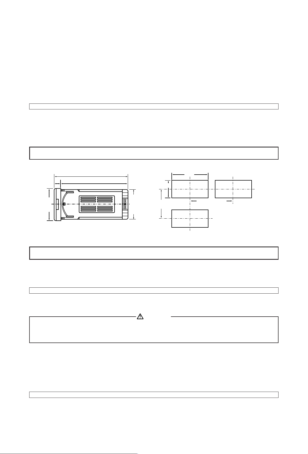
The installation panel should have a thickness of 1~3.5mm.
The instrument is of a press-and-fit type. Press it from the front so as to fit firmly into the panel hole.
NOTE: The DP21 indicator is of a panel fit-in type. It must be fitted in the panel for use.
2-2 Matters to be Attended to
There is inflammable or corrosive gas, soot or dust to impair insulation.
The ambient temperature is below −10˚C and above +50˚C.
The ambient humidity is above 90% RH and there is dew condensation.
The instrument is subjected to strong vibrations and shocks.
There is a strong electric circuit or a source of inductive interference.
There is exposure to water drops or direct sunlight.
Where the elevation is in excess of 2,000m.
NOTE: The environmental conditions belong to the installation category II of IEC664 and the degree of pollution is 2.
1
1 External Dimensions and Panel Cutout
2 Installation and Matters to be Attended to
In case where there is an intention to operate this product at one of the following sites, be aware that the occurrence
of life and/or other dangerous situations is considerable.
Exercise caution and avoid these places when selecting an operational site.
Unit: mm
Panel cutout
+08
92
0
10
110
100
45
+06
0
110mm or longer
48 × 96
60mm or
longer
44.6 × 91.6
CAUTION
Page 3
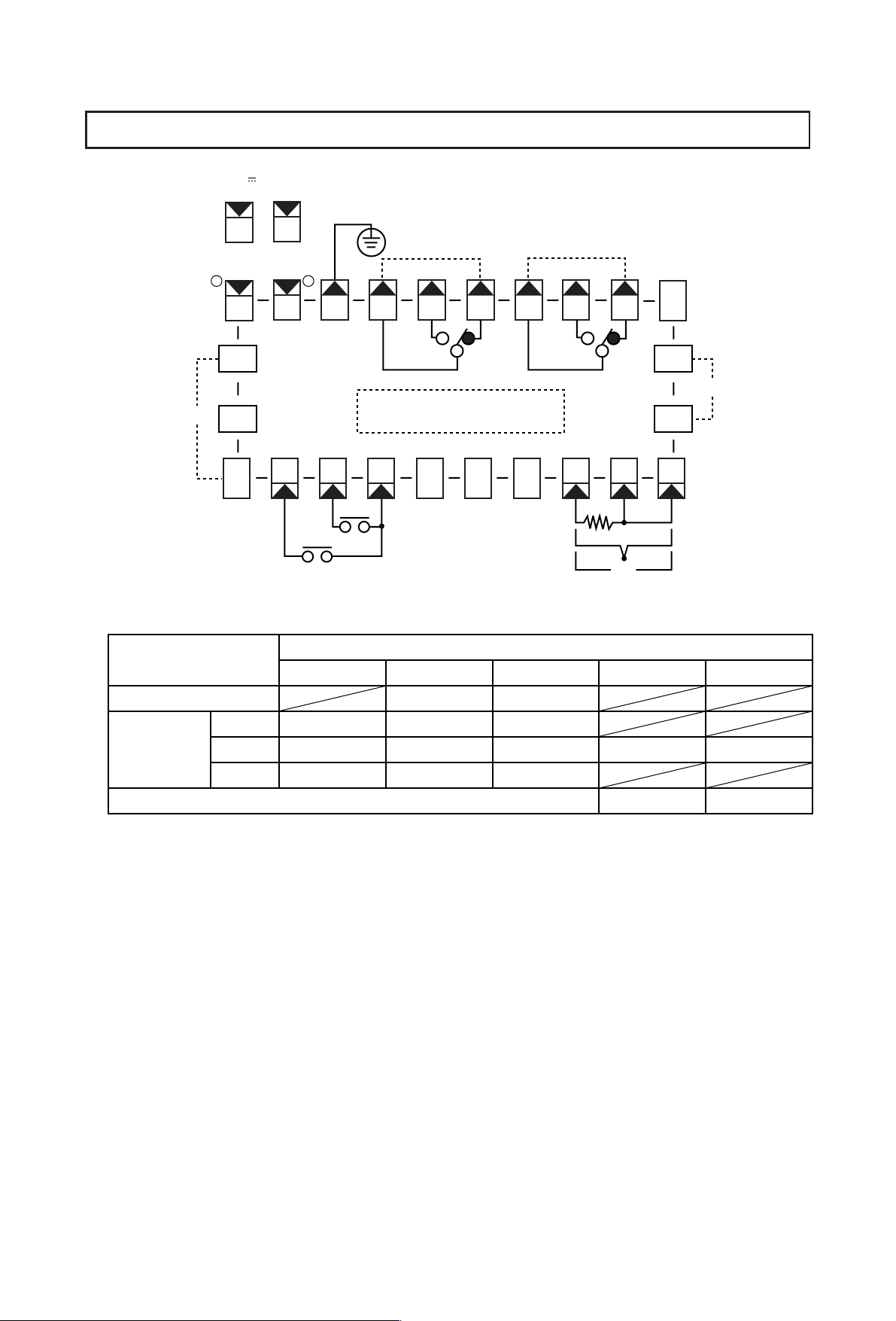
Alarm type such as lower limit alarm or higher limit alarm of alarm 1 and alarm 2 is selected by key
operation.
For both higher limit alarm and lower limit alarm, the C1-NO1 (C2-NO2 in the case of alarm 2) contacts are
closed when the set point of the alarm is reached.
2
3 Connection of Terminals
24V DC 5W/24V AC
50/60Hz 8VA
+ −
11
100−240V AC ~
50/60Hz 14VA
L N
11
12
12
13
ALARM1
2.5A 240V AC
14 15 16 17 18 19
NO1
22
∗
1
21
BCD OUTPUT
12345678910
RESET
HOLD
∗
1 Wiring Codes/Terminal Numbers for Each Function
Function
121222324
Analog output
−
C1
ALARM2
2.5A 240V AC
NC1
NO2
Terminal Numbers
+
C2
BBA
DC
NC2
−+
−+
20
24
23
∗
1
Communication
RS-232C
RS-422A
RS-485
SG
SG
SG
SD
SD −
−
DC output (24V DC 50mA)
RD
SD +
+
RD − RD +
− +
Page 4
For thermocouple input, use the designated compensating conductor and limit the external resistance to 100Ω or
below.
For R.T.D. input, the lead wire resistance should be 5Ω or less per line, and three lines should have the same
ohmic value.
Use of shielded cable for static induction and twist cable for electromagnetic induction is effective.
Connect the instrument to terminals according to the terminal diagram on page 2 and the wiring diagram attached
onto the instrument case.
Use a suitable press-fit terminal for the M3.5 terminal screw in the wiring for the instrument.
When wiring, use wire (1mm2minimum in sectional area) of 600V grade polyvinyl chloride insulated wire or
equivalent wire which has the same ratings.
NOTE: When the instrument is installed in a place subject to vibrations or shocks, use round press-fit terminals to
prevent disconnection from terminals.
NOTE: For wiring for power supply, etc., use wire as provided in the Electric Supplies Control Act.
Use wire 2mm2or larger for grounding. Grounding resistance should be 100Ω or less. The instrument
should be grounded at one point contact with the GND terminal.
Crossover wiring is not allowed.
•
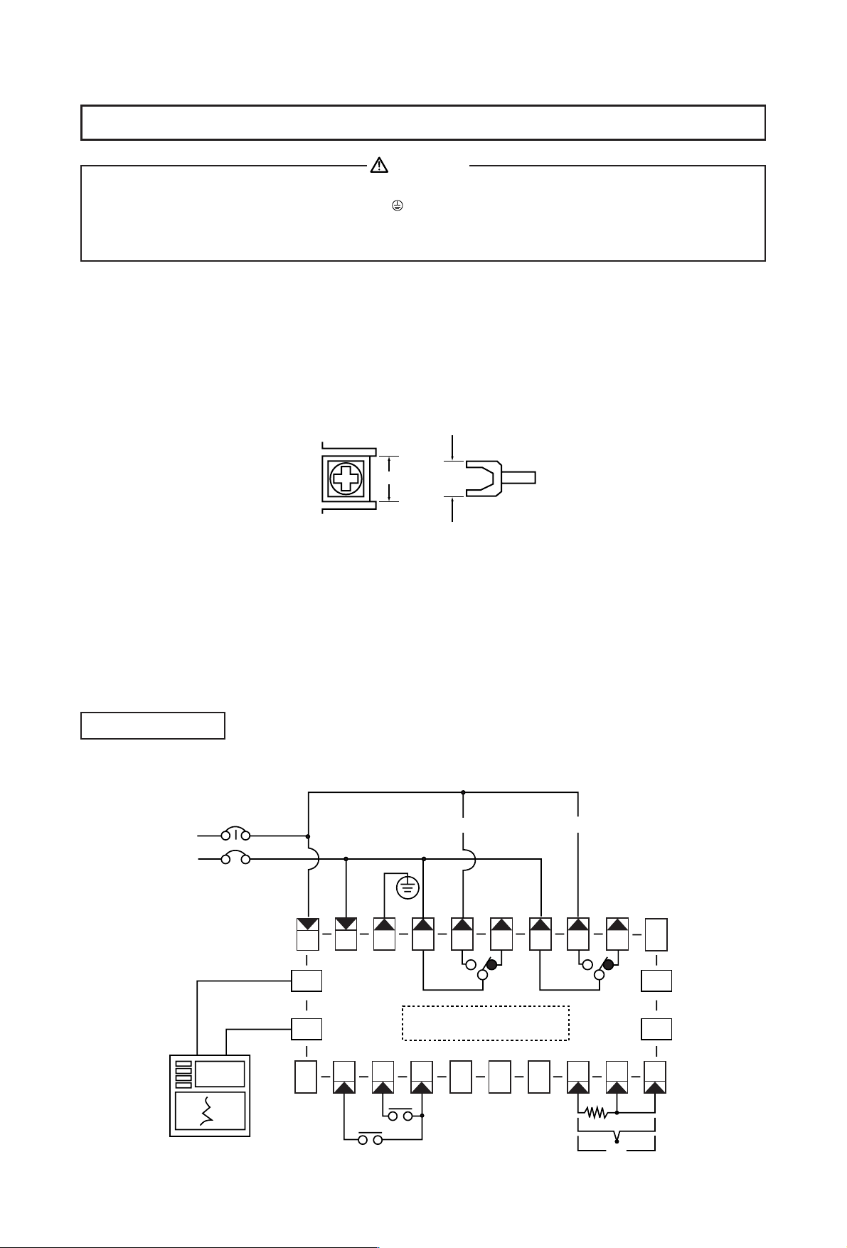
Example for the types with alarm and analog output functions
3
4 Wiring
•
Always disconnect this product from any power source during wiring operation to prevent electrical shock.
•
Be certain that the protective conductor terminal is properly grounded. Otherwise, a serious electric shock
may result.
•
Avoid touching the wired terminal and charged devices while supplying power.
Example of Wiring
WARNING
7.2mm
7.0mm max
Alarm 1 Alarm 2
Power
Analog output signal
0 ~ 10mV or
4 ~ 20mA
SR106
12
HOLD
13
RESET
NO1
C1
BCD OUTPUT
NC1
NO2
NC2
C2
BBA
DC
11
22
−
21
12345678910
14 15 16 17 18 19
20
24
23
−+
−+
Page 5
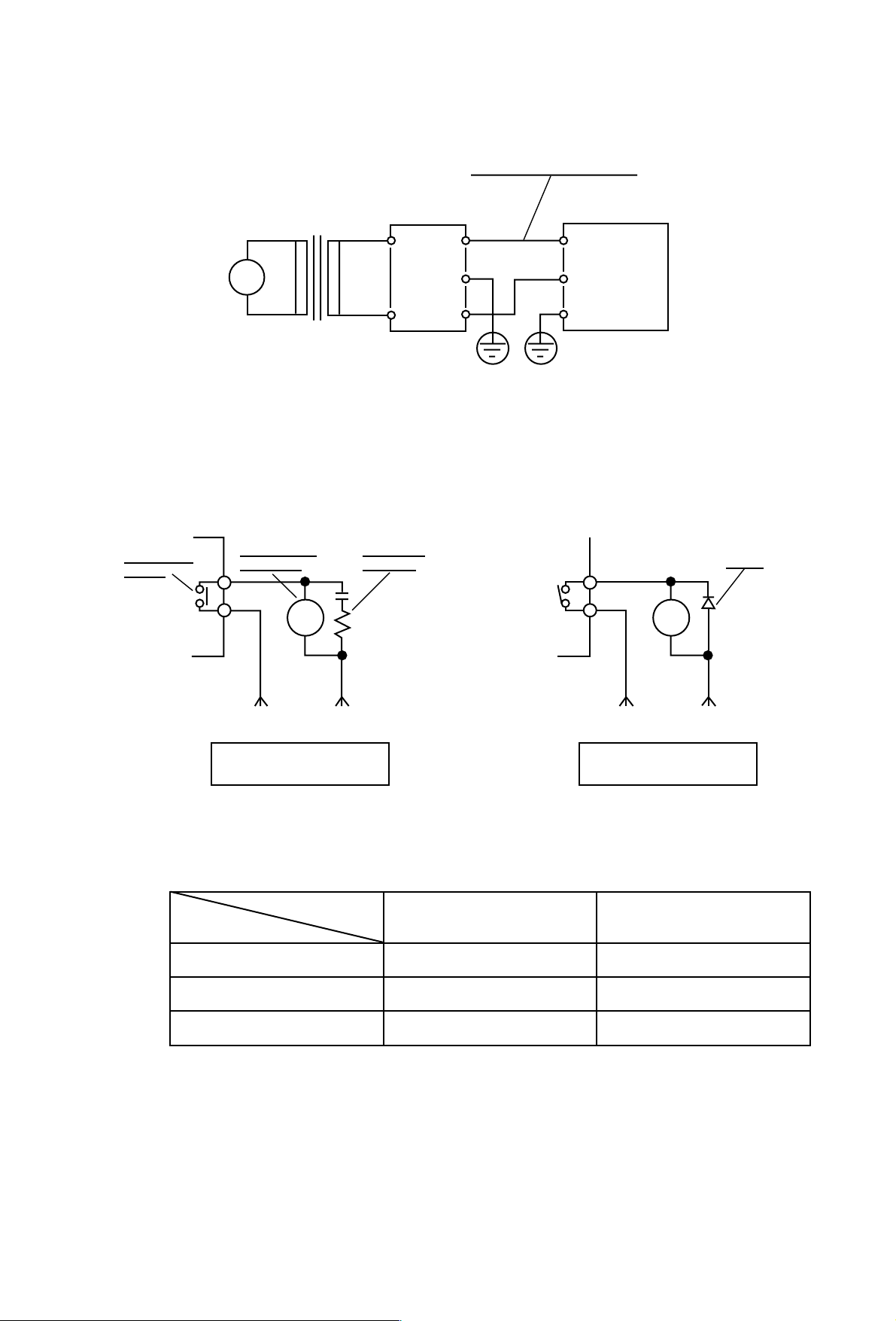
If there is significant noise from the power line, the installation of an insulating transformer and the use of a noise
filter are recommended.
In case such a load (inductive) as relay, electromagnetic switch or electromagnetic valve is driven via an alarm
relay contact, in order to get rid of sparks. A spark killer, CR (for AC) or diode (for DC) should be connected in
parallel with an exciter coil as shown below.
4
~
Insulating transformer
100/100V
200/200V
Noise filter
ground ground
Wire as short as possible
Indicator
100-240V AC
100-240V AC
50/60Hz
Recommended noise filter: TDK's ZMB2203-13
Alarm output
contact
Auxiliary relay
exciting coil
Spark killer
CR circuit
NO
RY RY
C
AC power supply
When AC supply is used
for auxiliary relay
DC power supply
When DC supply is used
for auxiliary relay
+ −
Diode
Typical Spark Killers (CR Filters)
Manufacturer
Shizuki Denki
Nittsuko
Matsushita Electric
SK25B473MA
CR2E333C121
ECQJ0187X
SK25B104MA
CR2E104C121
ECQJ0186X
Use
Small relay Electromagnetic switch
Page 6
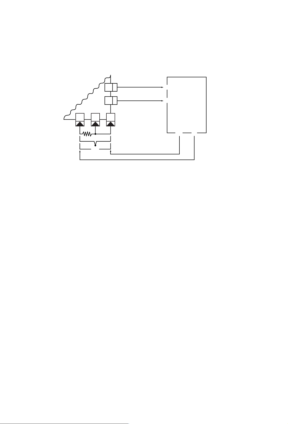
•
DC power supply for sensor
For this instrument, DC power supply (24V DC 50mA) for sensor can be selected to use an H71 or TH71 series
humidity sensor combinedly. (This can not be used in case of an 24V AC or DC supply.)
• H71 or TH71 series humidity sensor
5
8910
23
24
BBA
−
−
−
−
+
+
+
+
−+
DC
DP21
24V DC 50mA
POWER
H71/TH71
OUT
CH
Page 7
6
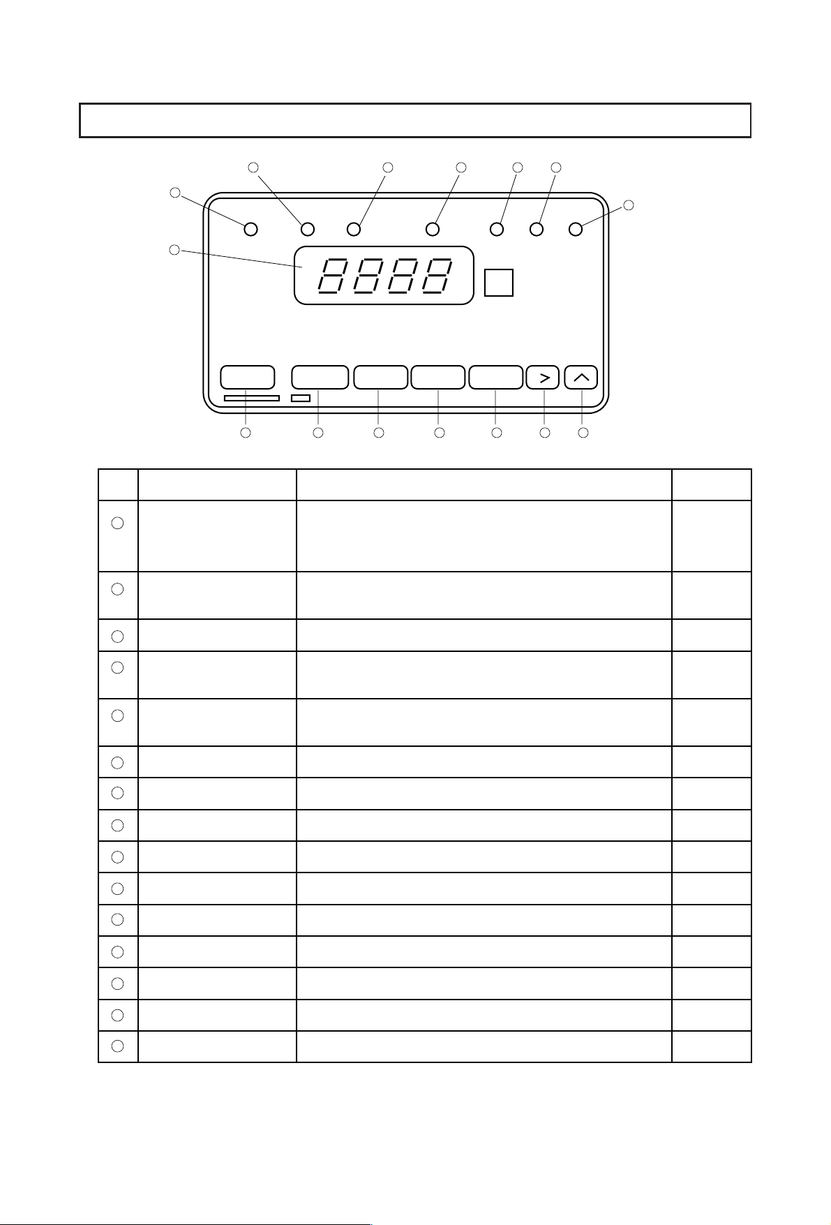
5 Front Panel Information
3 4 5 6 7
Display screen
1
2
Max value lamp
(MAX)
2
1
Max value
lamp
Display key Alarm key
Min value
lamp
Communication key
Hold
lamp
Communication
lamp
Range key Setting key
12131415
Name Function
Displays PVs.
Displays parameters and figures when various functions
are set.
Remains lit while a max value is shown on display
screen by means of display key.
Alarm 1
lamp
Alarm 2
lamp
Range
lamp
9
1011
8
3
Min value lamp (MIN)
4
Hold lamp (HOLD)
5
Communication lamp
(COM)
Alarm 1 lamp (AL1)
6
7
Alarm 2 lamp (AL2)
8
Range lamp (RNG)
9
Up key
Shift key
10
11
Setting (SET) key
Range key
12
Alarm (ALM) key
13
Communication key
14
Remains lit while a min value is shown.
Remains lit while a processing value is held by means of
an external signal.
Remains lit while in the communication mode.
Lights when the alarm 1 function is put to work.
Lights when the alarm 2 function is put to work.
Remains lit while the range block is operated.
Increases a PV.
Takes a figure up or down.
Registers a set value.
Moves to the range block.
Moves to the alarm block.
Moves to the communication block.
Option
Option
Option
Option
Option
15
Display key
Moves to the display block.
Page 8
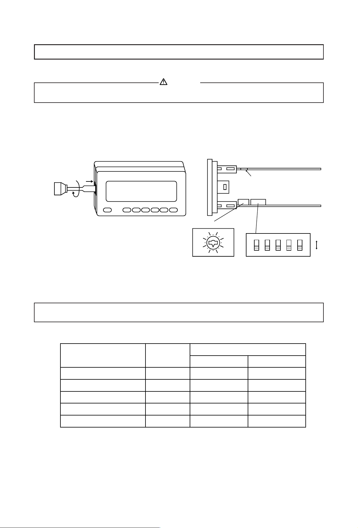
6-1 How to Detach Inner Body
When the instrument is removed/replaced in the case, make sure the power is off. If it is done while the power is
on, it may lead to problems with the product and/or other problems.
To set a function or to select a measuring range, the inner body has to be drawn out.
Insert a minus screwdriver of 6mm~9mm into the opening (where packing is exposed) of the front case and rotate
the screwdriver while pushing up the lock lever behind the packing. Once the instrument comes out by a few
millimeters, you can remove it by hand.
6-2 Selection of Function (SW2)
Select a function from the table and set it by means of a dip switch (SW2). Unless otherwise designated, all the
switch knobs, codes 1 ~ 5, are pressed down (OFF) in the initial setting.
7
6 Selection of Measuring Range and Functions
NOTE: The switch is set to ON or OFF easily when the switch knob is pressed by means of a thin tool such as a
pincette or a small screwdriver. The switch tends to break if an unnecessarily high force is applied.
CAUTION
How to detach inner body Position of switches (on the right side)
Cut-out portion
Front
panel
SW2
SW1
SW1
8
A
6
4
C
E
2
0
SW2
1
2
3
4
Table for Function Selection
Switch Knob Position
Function/Feature Switch code
Down (OFF) UP (ON)
Display renewal cycle
RTD input standard
Alarm
1
2
3
0.25 sec
JPt (Former JIS)
Non-standby
2.0 sec
Pt (JIS/IEC)
Standby
ON
5
OFF
Key lock
Unit
4
5
Unlocking
˚C
Lock setting
˚F
Page 9

6-3 Selection of Measuring Range
Select a measuring range from the table and set it by turning the rotary switch (SW1).
It is suggested that the set type of input and measuring range would be written on the label on top of the instrument.
When you operate the rotary switch, draw out the apparatus illustrated and
insert a thin minus screwdriver through the cut-out portion on the top into
the groove of the rotary switch. Rotate it to the intended setting point.
Standard Thermocouple RTD
B, R, S, K, E, J, T=JIS/ANSI/DIN/IEC JPt100=(old) JIS
WRe5/26=(Hosking Mfg. Co.) Pt100=(New) JIS/DIN/IEC
U, L=DIN 43710
*1 Thermocouple B: Accuracy not guaranteed below 400˚C (750˚F)
*2 Thermocouple K: 70.0 ~ 400.0 (Unit: Kelvin only) Codes 1K A67 05
*3 RTD: Accuracy ±0.2˚C
8
0
8
A
C
E
6
4
2
Top of the apparatus
Cut-out portion
SW1
Front
panel
1B
1R
1S
1K
1E
1J
1T
1W
1U
1L
1K
2J
2F
32
34
36
41
42
62
64
66
Input
Type Code ˚C Reading Code ˚F Reading Code
Rotary Switch Code
Measuring Range
Thermocouple
RTD
mV
mA
V
B *1
R
S
K
E
J
T
WRe5/26
U
K
K *2
JPt100
(JIS)
Pt100
(JIS/IEC)
0 ~ 10
0 ~ 50
0 ~ 100
0 ~ 20
4 ~ 20
0 ~ 1
0 ~ 5
0 ~ 10
A47
A46
A46
A74
A27
A09
A26
A30
A49
A30
A08
A67
A31
A02
A31
A02
A65
A64
A64
A79
A72
A63
A71
A77
A66
A77
A62
A78
A61
A78
A61
A
8
9
0
1
3
2
4
7
5
6
−
B
C
B
C
D
E
F
E
F
D
E
F
0 ~ 1800
0 ~ 1700
0 ~ 1700
−200 ~ 1200
−100.0 ~ 800.0
0.0 ~ 700.0
−100 ~ 600.0
−199.9 ~ 200.0
0 ~ 2300
−199.9 ~ 200.0
0.0 ~ 600.0
70.0 ~ 400.0
−199.9 ~ 600.0
0.00 ~ 99.99 *3
−199.9 ~ 600.0
0.00 ~ 99.99 *3
32 ~ 3272
32 ~ 3092
32 ~ 3092
−328 ~ 2192
−148 ~ 1472
32 ~ 1292
−148 ~ 1112
−328 ~ 392
32 ~ 4172
−328 ~ 392
32 ~ 1112
−328 ~ 1112
32.0 ~ 212.0
−328 ~ 1112
32.0 ~ 212.0
The scaling function allows you to set a
measuring range freely.
scaling range: −1999 ~ 9999 count
span: 100 ~ 10000 count max
Page 10

Although this series is designed for multirange and programmable range measurement, the instrument has been set
as follows prior to the shipment:
The apparatus is attached with unit display sheets. Use whichever you like.
9
Type of input
Thermocouple
R. T. D.
Voltage
Current
Voltage
JIS K
JIS Pt 100
0 ~ 10mV
4 ~ 20mA
0 ~ 1V
−100.0 ~ 800.0˚C
−199.9 ~ 600.0˚C
0.0 ~ 100.0 without unit
0.0 ~ 100.0 without unit
0.0 ~ 100.0 without unit
Standard/Rating Measurement Range
Unit
3
Unit
3
Unit
3
Code
Nil
˚C
˚F
%RH
%
K
mV
V
mA
A
W
µ S/cm
mbar
bar
psi
Psig
Pa.
kPa
mmH
2O
mH
2O
00
01
02
03
04
05
06
07
08
09
10
11
12
13
14
15
16
17
18
19
20
21
22
23
24
25
26
27
28
29
30
31
32
33
34
35
36
37
38
39
40
41
42
43
44
45
46
47
48
49
50
51
52
53
54
55
56
57
58
59
inH
2O
mmHg
cmHg
inHg
1/s
kg/h
kg/cm
2
kgf/cm
2
Torr
mmAq
1/min
1/h
m
3
/min
m3/h
Nm3/min
Nm
3
/h
mm/s
m/s
m/min
m/h
m/s
2
rpm
mm
cm
m
mm
3
cm
3
m
3
in
1b
g
kg
t
1
ppm
pH
cal
kcal
Nil
Nil
Code Code
Page 11

10
7 Parameters
DISPLAY BLOCK
Current PV
display screen
[Communication block]
Communication
Communication
Data bit length Type of Alarm 1
Display
key
Display
key
Maximum value Minimum value
[Parameter setting block]
[Alarm block] [Range block]
value
Alarm 1
hysteresis
Alarm
Alarm
Alarm
Alarm
key
key
key
Position of
decimal point
Display S L side
*1
Display S H side
*1
Communication key key key
Alarm 1 set
mode
Communication key
address
Communication key
Communication key
Display
Input V/I Input TC/RTD
Range
Range
Range
Range
key
Sensor
compensation
key
key
key
Range
Range
key
key
Communication
speed
Communication key
Delay time
Communication key
Release of
latching
Alarm
Alarm 2 set
value
Alarm
Alarm 2
hysteresis
Alarm
Type of Alarm 2
Alarm
Release of
latching
Alarm
key
key
key
key
key
Analog S L side
*2
Analog S H side
*2
Range
Range
Parameters enclosed by
dotted lines are for
additional (optional) functions.
key
key
*1 Display S: Display scaling
*2 Analog S: Analog output scaling
Page 12

The parameters of the DP21 series indicator are shown on page 10.
They are divided to the display block and the parameter setting block, which is further divided into three sections.
7-1 Display Block
Pressing the display (DISP) key repeatedly shows PV value → maximum value → minimum value.
7-2 Parameter Setting Block
7-2-1 Range Block
In the case of DC voltage or current input, higher and lower limit values of display range and the position of
decimal point are set. In the case of sensor input, a sensor compensation and an output range if the optional
analog output function is included, are set.
7-2-2 Alarm Block (Additional/optional function)
An action type of Alarm 1 or 2, hysteresis, action point and release of latching (holding of alarm action) are
set.
7-2-3 Communication Block (Additional/Optional function)
Communication mode, communication address, the length of data bit, the speed of communication and the
time of delay are set. (For details, please refer to the instruction manual for communication interface.)
11
Page 13

8-1 Display when power is applied
When power is applied to the instrument, the following characters and figures appear on the display screen at
intervals of about one second, and then the current processed value is displayed.
8-2 Display Block (Common to all input types)
Repeatedly pressing the key brings PV, maximum and minimum values onto display.
When the key is pressed while operation is going on by means of any key other than the key, the
processed value display is returned.
When any key other than the key is operated and that operation is interrupted for more than a minute, the
processed value returns to the display.
While the maximum processed value is on display, the maximum value lamp remains lit.
While the minimum processed value is on display, the minimum value lamp remains lit.
DISP
DISP
DISP
DISP
12
8 Operating Procedure
Applying
power
Name of series
No. of software
Lower limit of measuring range
Lower limit of measuring range
Contents of functions included in the instrument
Function without
Alarm
Analog output
BCD code
Communication
0
0
0
0
with
1
1
1
1
Processed value
Page 14

8-3 Holding PV Value
When the terminals #2 and #4 are short-circuited by an external contact signal, the processed value at the time of
short-circuiting is held and displayed prior to the current processed value. (The hold lamp lights.)
Even while the hold lamp is lit, the maximum and minimum values can be displayed by operating the key.
8-4 Release (Reset) of Display of Maximum/Minimum PV Values
When the terminals #2 and #4 are short-circuited by an external contact signal, display data of maximum and
minimum values are released (reset).
Releasing (Reset) by Keyboard Operation
Pressing the entry ( ) key twice consecutively when the maximum value is on display also functions to release.
* Maximum/minimum processed values are initialized (reset) upon turning power ON.
8-5 Range Block
8-5-1 Sensor Compensation Function (Input shift) for Sensor
(thermocouple or R.T. D.) Input Type
SET
DISP
13
Type of Displays in Display Block
Current processed value display
key
DISP
Maximum (peak) processed value display
key
DISP
Minimum (bottom) processed value display
key
DISP
Sensor compensation
Processed value
key
RNG
Sensor compensation
The range lamp lights.
Entry ( ) key
SET
Compensation value set by means of the and keys
Registration by means of the entry ( ) key
key
DISP
SET
Processed value (after sensor compensation)
The range lamp goes out.
Page 15

Setting Range of Sensor Compensation
Thermocouple input: ±99.9 or ±999 Unit
R.T.D. input: ±99.9 or ±9.99 Unit
Sensor compensation function
This is the function for displaying input as value added with a predetermined bias. It is used when a
processed value is lower than the actual value due to sensor error, etc., or compensation is necessary for a
processed value which is within the precision range but varies from the value(s) obtained by other
instrument(s).
8-5-2 Voltage/Current Input Type
(1) Setting decimal point
Pressing the range key when the processed value is on display brings the characters onto display,
allowing selection or setting of the position of decimal point.
* When the decimal point is set at the third position from the right, the display shows .000, not 0.000.
(2) Setting lower limit of measuring range
Display scaling function
Setting range: −1999 ~ 9899 Initial Value: 0.0
Pressing the range key twice in the current measuring range display screen brings the characters
(lower limit of measuring range) onto display.
When the setting key is pressed, the display changes to figures.
Use the and keys to set a desired value in the place of the flashing figure and register it by the use
of the entry key.
14
RNG
key
SET
DISP
key
Processed value display
Decimal point flashes (change of position allowed)
Processed value display
Setting the position of decimal point
The range lamp lights.
Desired position is set by the use of key and register it by the use
of the entry key (completion of position change).
The range lamp goes out. Pressing the key calls the processed
value back onto display.
Entry ( ) key
Page 16

* Scaling of Measuring Range
Measuring range: −1999 ~ 9999
Tha span between the lower and higher limits can be set as desired in a range from 100 to 10000 counts.
(3) Setting higher limit of measuring range
Display scaling function
Setting range: −1899 ~ 9999 Initial value: 100.0
Pressing the key in the preceding screen for measuring range lower limit setting calls the
(measuring range higher limit setting) screen.
For setting, follow the same steps as measuring range lower limit setting in (2) above.
8-5-3 Analog Output Scaling Function
Additional (optional) function/range block
Analog Output
This is the function to output an analog voltage or current correspondingly to the processed value. The output
can be used as an input signal into a recorder or a data collector.
(1) Analog output scaling lower limit setting
Setting range: within measuring range
Initial value: the same as measuring range
(This display does not appear if the function is not added.)
RNG
15
RNG
key
RNG
key
SET
DISP key
Processed value display
Measuring range lower limit setting screen
Current lower limit value is displayed
Processed value display screen (Completion of setting)
Setting by the use of and keys and registration by the
use of entry key.
Entry ( ) key
Page 17

(2) Analog output scaling higher limit setting
Setting range: −1999 ~ 9999
Initial value: same as measuring range
Pressing the key in the preceding screen for analog output lower limit setting calls the
(analog output scaling higher limit) setting screen.
For setting, follow the same steps as lower limit setting in (1) above.
RNG
16
RNG
SET
twice (ShFt→AoL/Sensor input)
4 times (dp→Sc_L→Sc_H→Ao_L/V,I input)
Analog output lower limit processed value
Analog output lower limit measuring value
Analog output
Scaling lower limit setting screen
Use the and keys to set a desired value in the place of
flashing number and register it by the entry key.
Entry ( ) key
SET
Entry ( ) key
Press ( ) key
*
Scaling Output
100%
Analog
output
0%
Setting range
An analog signal corresponding to PV is output
within a measuring range defined by and
.
* When you have changed the measuring
range, make sure to confirm the scaling
value of the analog signal.
Page 18

8-6 Alarm Block
The instrument can be added with the two optional alarm functions, Alarm 1 (AL_1) and Alarm 2 (AL_2).
* The deviation in Alarm 2 is relative to the set value in Alarm 1.
* If (the amount of deviation) is set at a low value and hysteresis is large in the (deviation
higher/lower limit) mode, alarm actions overlap and it may happen that releasing will not be possible once an
alarm is output.
Therefore, values have to be set lest hysteresis should overlap.
17
Setting of alarm
Type 1
Setting of alarm
Type 2
[ ]
Absolute value higher limit alarm
[ ]
Absolute value lower limit alarm
[ ]
Deviation higher limit alarm
[ ]
Deviation lower limit alarm
[ ]
Deviation higher and lower limit alarm
[ ]
Absolute value higher limit alarm
[ ]
Absolute value lower limit alarm
ON
ON
ON
ON
ON
ON
ON
ON
PV
Alarm Function
Alarm 1 set point Alarm 2 set point
Page 19

8-6-1 Latching alarm (to be designated at the time of ordering)
Once an alarm is output, the state of output is maintained after the processed value gets out of the alarm action
range. It is released by operating the front keyboard (See the "Releasing Latching Action" section).
18
ALM SET
ALM SET
ALM SET
ALM SET
ALM SET
ALM SET
ALM SET
ALM SET
ALM
Processed value display
Alarm 2
Alarm setting 2
Alarm setting 1
Hysteresis
setting 1
Hysteresis
setting 2
Alarm type
selection 1
Alarm type
selection 2
Latching
action release 1
Latching
action release 2
Set desired value in the place
of flashing figure by means of
the and keys.
Register by means
of the entry key.
Register by means
of the entry key.
Register by means
of the entry key.
Register by means
of the entry key.
Register by means
of the entry key.
Register by means
of the entry key.
Register by means
of the entry key.
Register by means
of the entry key.
Set desired value in the place
of flashing figure by means of
the and keys.
Set desired value in the place
of flashing figure by means of
the and keys.
Set desired value in the place
of flashing figure by means of
the and keys.
Select one out of 5 types by
means of the key.
key key
key key
key
,
,
,
Parameters in Alarm Block
ON
ON
OFF
OFF
OFF
OFF
Ordinary alarm
Latching alarm
Lower limit alarm
Alarm set point
Hysteresis
Higher limit alarm
Latching in action
Latching released by key
Range in which latching can be released.
Latching actions
movement of PV
Page 20

19
Releasing Latching Action
(An example of release of latching/releasing not possible while an alarm is output.)
Pressing the alarm key four times consecutively brings the parameter onto the display.
Then, pressing the setting/entry key brings onto display flashes when the key is pressed to indicate that
this state can be changed now. Pressing the key again changes the display to which flashes. When the
entry/setting key is pressed, it stops flashing and the alarm latching action is released.
ALM
SET
REGDISP
ALM
Processed value display
4 times
Setting release of latching 1
Latching in action
The "rSEt" state possible to
be changed.
The "KEEP" state possible to
be changed.
Release of latching
Flow Chart of Releasing Latching Alarm
Page 21

NOTE: If BCD output function is added, CE marking does not apply.
20
9 Codes for Instrument Selection
Item Code Specification
1. SeriesDP21-48 × 96 DIN Size Digital Instruction Scale
2. Input ThermocoupleB, R, S, K, E, J, T, WRe5-26, U, L Multi-input
RTD Jpt 100/Pt 100 Multi-input
Voltage (mV) 0~10, 0~50, 0~100mV DC
Current (mA) 0~20, 4~20mA DC
Voltage (V) 0~1, 0~5.0, 0~10V DC
K. T. C. (Thermocouple) for Kelvin (K) Unit (Measuring 70.0~400.0K)
3. Power Supply 90 -
10 02 -
100−240V AC ±10% 50/60Hz
24V AC ±10% (50/60Hz)
24V AC ±10%
4. Alarm None
None
Japanese
English
Without
With
24V DC 50mA
None
0~10mV DC Output resistance 10Ω
4~20mA DC load resistance below 300Ω
0~10V DC max load current below 2mA
RS-485
RS-422A
RS-232C
BCD
Individual settings and outputs 2 points (1c contact)
contact capacity = 250V AC 2.5A/resistive load
Scaling
(within measuring range)
When communication function is
selected, Item 6. DC power supply
for sensor cannot be selected.
Same as above with latching function
5. Analog output and
communication function
6. DC power for sensor
(Selection not possible in case
power supply is 24V AC or DC)
7. Front sheet letter
8. Remarks
1
2
3
4
6
8
00
00
03
04
06
15
16
17
20
J
E
0
9
00 24 -
10
11
Multi-input programmable range
Scaling range: −1999~9999 counts
Span: within a range count from
100~10000
When 24V DC or AC is selected, Item 6.
DC power for sensor cannot be selected.
Page 22

10-1 Identifying cause of trouble
If something goes out of order, (A) investigate input/output, (B) confirm that the wiring and terminals are in order
and not loose, and (C) check the relevant settings. If you have any queries regarding problems or the handling of the
instrument, please call our company.
10-2 Display in case of input problems
21
10 Troubleshooting
Type of Input
Problem Display
Thermocouple disconnection
Cold contact compensation
rose to +80˚C or more.
Cold contact compensation
down to −20˚C or lower.
10000 ~ 10999 counts when
input is within +10% of
measuring range.
Input is +10% or more above
measuring range.
−2000 ~ −2999 counts
when input is within −10%
of measuring range.
Input is −10% below
measuring range.
Thermo-
couple
input type
RTD
input type
Voltage/
current
input type
Terminal No.
A
B
B
disconnection of
terminal number 8
8
disconnection of
terminal number 9
9
disconnection of
10
terminal number 10
Error in display
Page 23

22
SPECIFICATIONS
•
Display:
· Range Display: 7-segment LED (4-digit)
· Displays: Measuring range, max. hold, bottom hold
· Display Accuracy: ±0.25% + 1 digit of measuring range
(Thermocouple B: Accuracy not guaranted
below 400˚C (700˚F))
· Display Cycle Range: 0.25 sec. or 2 sec. (by internal switch)
· Legend Change: ˚C and ˚F (by internal switch)
· Monitor Display: Max., min., hold, communication, alarm
and range
•
Setting:
· Setting Method: By front key
· Setting Keys: Display, Communication, Alarm, Range,
Setting, Shift and Up
· Type of Setting: Position of decimal point, display scaling,
sensor compensation, analog output
scaling, alarm, alarm sensitivity, latching
OFF, communications (interface), etc.
•
Input:
· Sampling Cycle: 0.25 sec.
· Thermocouples: T, J, E, K, R, S, B, WRe5-26, DIN 43710
U & L
Kelvin Legend: 70.0~400.0K (available only T/C 'K',
option)
Input Resistance 500kΩmin.
External Resistance
Allowable Range: 100Ω max.
Sensor Compensation: ±99.9 or ±999 Unit (depending on
communication signal)
Burnout Scaling: Up-scale (standard feature)
· R.T.D.: JPt100/Pt100 (DIN/JIS) changeable
Rated Amperage: Approx. 0.5mA
Lead Wire Resistance: 5Ω max. per wire
Sensor Compensation: ±99.9 or ±9.99 Unit (dependeng on
communication signal)
· Voltage: 0~10mV, 0~50mV or 0~100mV DC
changeable
0~1V, 0~5V, 0~10V DC changeable
Input Resistance: 500kΩ min.
· Current: 4~20mA or 0~20mA DC changeable
Receiving Resistance: 250Ω
· Display Scaling: Only voltage and current inputs available
(−1999~+9999, 100~10000 counts)
Setting Method & Decimal Point Position: By front key
· Isolation: Between input and internal circuit
•
External Control
· HOLD: Present value is maintained by external
contact signal
· RESET: Maximun value or minimum value is
released by external contact signal.
· Isolation: External contact signal input is isolated
from the system and various types of
output (not isolated from sensor input,
however)
•
Data storage: By non-volatile memory (EEPROM)
•
Operating Ambient Conditions
Operating ambient temperature/humidity ranges:
−10 to +50˚C / 90% max. (no dew
condenstation)
Limit in altitude: 2000 meters above sea level or lower
Category: II
Degree of pollution: 2
•
Applicable standards: Safety: IEC1010-1 and EN61010-1
EMC: EN61326
During EMC testing, the apparatus
continues to operate at a measurement
accuracy within ± 10%FS.
•
Optional Functions:
Alarm:
· Alarm Points: 2 Point
· Alarm Method: Individual Setting/individual output
· Alarm 1: Absolute value high limit or absolute value
low limit (selectable)
· Alarm 2: Absolute value high limit, absolute value
low limit,
deviation high limit, deviation low limit or
deviation high/low limit (selectable)
Deviation high limit, deviation low limit
and deviation high/low limit alarm can be
selected deviation for alarm 1.
· Alarm Setting Range: −1999~9999 (absolute value high limit,
absolute value low limit, deviation high
limit and deviation low limit)
1~9999 (deviation high/low limit)
· Alarm Setting: By front key
· Alarm Sensitivity: 0.2~9.9 or 2~99 by front key
· Alarm Output: 1c contact, 250V AC, 2.5A/Resistive load
· Inhibit/Non-Inhibit: Selectable by internal switch
· Latching Alarm: Available as option
•
Analog Output:
· Output: 0~10mV DC (output resistance: 10Ω)
0~10V DC (load current: 2mA max.)
4~20mA DC (load resistance: 300Ω max.)
· Output Accuracy: ±0.25%FS of diplay value
· Resolution: Approx. 0.0125FS (1/8000)
· Isolation: Isolated between input and internal circuit
· Output Scaling: By front key
•
Interface:
· Type of Interface: RS-232C, RS422A or RS-485
· Speed: 1200, 2400, 4800, or 9600 bps selectable
· Data Bit: 7-bit odd-parity or 8-bit w/o parity
selectable
· Address: 0~31
· Code: ASCII Code
· Isolation: Isolated between input and internal circuit
•
Sensor Power Supply: 24V DC (±3V) 50mA
•
Power Supply: 100-240V, AC, 50/60Hz, 24V AC or 24V DC
Power Consumption: 100-240V, AC: approx. 14VA
24V AC: approx. 8VA, 24V DC: approx. 5W
•
Insulation Resistance: 500V DC 20MΩ between input terminal
and power supply terminal
500V DC 20MΩ between input terminal
and protective conductor terminal
•
Dielectric Strength: One minute at 2300V AC between input
terminal and power supply terminal
One minute at 1500V AC between power
supply terminal and protective terminal
•
Protective strength: Only front panel has simple dust-proof and
drip-proof structure
•
Material: Resin molding
•
External Dimensions: 48(H) × 96(W) × 110(D) mm
•
Mounting: Push in panel (one-touch mount)
•
Panel thickness: 1.0~3.5mm
•
Size of mounting hole: H45 × W92mm
•
Weight: Approx. 300g
Page 24

23
M E M O
 Loading...