

Page 1

User's Guide
http://www.omega.com
e-mail: info@omega.com
GPIB HARDWARE MANUAL
FOR USE WITH
PCI-GPIB, ISA-GPIB
Page 2

CHAPTER ONE: INTRODUCTION ......................
CHAPTER TWO: INSTALLATION ...................
1
11.1 HISTORY ..........................................
11.2 GPIB SYSTEM DESCRIPTION ........................
11.2.1 Talkers, Listeners, and Controllers ..................
21.2.2 GPIB Electrical Signal Configuration ................
31.2.3 Connection Configurations .........................
5
52.1 PCI-GPIB ..........................................
62.2 ISA-GPIB ..........................................
82.3 ISA-GPIB/LC .......................................
102.4 PCM-GPIB ........................................
112.4.1 Windows 95 ....................................
112.4.2 Windows 3.1 ...................................
122.5 PC104-GPIB .......................................
142.6 CPCI-GPIB ........................................
Page 3

Chapter One: INTRODUCTION
1.1 HISTORY
The GPIB (General Purpose Interface Bus) has become the worldwide standard for
connecting instruments to computers. Invented in the 1960s by Hewlett Packard and
originally designated as HPIB, the bus specification was eventually adopted by a wide
variety of both instrument and computer manufacturers. The original specification was
documented and sanctioned by the Institute of Electrical and Electronic Engineers as
IEEE-488.
The advent of the inexpensive and powerful personal computer has driven the GPIB
market through explosive gr owth. As GPIB bus usage expanded, ther e arose the ne ed
for some additional capability and standardization, so in 1987, IEEE-488.2 was
adopted. IEEE-488.2 was revised/ammended in 1992 and represents the current GPIB
specification. The new specification provides some standardization among compliant
instruments. These standardization greatly simplifies the job of the GPIB system
designer since 488.2 compliant instruments share common programming conventions.
1.2 GPIB SYSTEM DESCRIPTION
1.2.1 Talker
A GPIB device can be a
Talker sends data to one or more Listeners, A Listener accepts data from a Talker and
a Controller manages the flow of information over the bus. A GPIB Digital Voltmeter
is acting as a Listener as its input configurations and ranges are set, and then as a
Talker when it actually sends its readings to the computer.
The Controller is in charge of all communications over the bus. The Controller’s job
is to make sure only one device tries to talk at a time, and make sure the correct Listeners are paying attention when the Talker talks. Each GPIB system has a single system controller. The system controller is ultimately in charge of the bus, and is in
control as the bus is powered up. There can be more than one Controller on the bus
and the System Controller can pass active control to another controller capable device,
though only one can be Controlle r In Charge at a given time. The
GPIB board is usually designated as the System Controller.
1.2.2 GPIB Electrical Signal Configuration
Listeners
s,
Controllers
, and
Talker, Listener
, and/or
1
Controller
. As the name implies a
Page 4
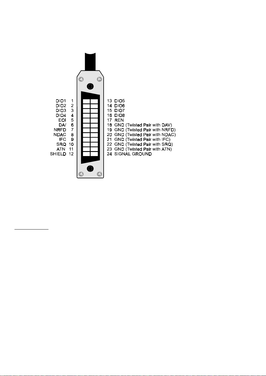
The GPIB is an 8-bit parallel data tr ansfer bus. In addition to the 8 data bits, the bus
carries three handshaking lines and five GPIB specific management and control lines.
The remainder of the standard 24 pin GPIB cable is used for the cable shield, signal
grounds and returns. The GPIB connector pin-out is shown in the diagram below:
Standard GPIB Cable/Connector
DATA LINES
DIO1 through DIO8 are the data transfer bits. Most GP IB systems send 7-bit data
and use the eight bit as a parity or disregard it entirely
2
Page 5

HANDSHAKING LINES
There are three handshaking lines that control the data transfer between devices.
NRFD (Not Ready For Data): this bit is used to indicate the readiness (or lack
thereof) of a device to accept data
DAV (Data Valid): bit is used to indicate to receiving devices that data has been
placed on the bus and is available to read.
NDAC (Not Data Accepted): is asserted by the receiving device to indicate that data
has been read and may now be removed from the bus.
SYSTEM MANAGEMENT LINES
ATN (Attention): is used by the controller to specify how data on the DIO lines is
interpreted and which devices must respond to the data
IFC (Interface Clear): is used by the system controller to place the entire system in a
known quiescent (Cleared) state and to assert itself as Controller In Charge (CIC).
SRQ (Service Request): is used by a device on the bus to indicate the need for attention and requests an interrupt of the current event sequence.
REN (Remote Enable): is used by the controller in conjunction with other messages
to place a device on the bus into either remote or local mode
EOI (End or Identify): Is used by Talkers to indicate the end of a message string, or
is used by the Controller to command a polling sequence.
1.2.3 Connection Configurations
The GPIB specification is quite definitive regarding the number of devices and cable
lengths allowed in a GPIB system. There can be no more than 15 devices on a single
contiguous GPIB bus. Larger systems are possible by installing additional GPIB interface boards in your computer
The maximum, total length of all cables on a single GPIB system is 20 meters. In
addition, cable length between consecutive devices may be no greater than 4 meters,
and average cable length must be 2 meters or less. Stated another way, the total cable
length (in meters) in the system may not be longer than 2 times the number of devices
(up to 20 meters). Longer length systems are possible, but only with the use of a GPIB
extender card.
In addition to the above rules, at least two thirds of all devices on the bus should be
powered on for proper operation.
3
Page 6
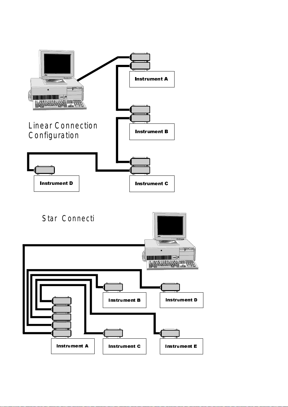
Keeping the above constraints in mind, there is no limitation on the actual connection
scheme used to connect the GPIB devices together. Star, Linear or any combination of
both may be used. These are shown in the following diagrams.
,QVWUXPHQW $
Linear Connection
Configuration
,QVWUXPHQW '
Star Connection
Configuration
,QVWUXPHQW %
,QVWUXPHQW &
,QVWUXPHQW %
,QVWUXPHQW '
,QVWUXPHQW $
,QVWUXPHQW & ,QVWUXPHQW (
4
Page 7

Chapter Two: INSTALLATION
The following sections describe the hardware installation procedure for GPIB boar ds.
After hardware installation, please refer to your GPIB software installation guide for
additional setup and operation details.
2.1 PCI-GPIB
The PCI-GPIB board is completely plug and play. To install this boar d into your system follow the simple steps shown below.
1. Turn your computer off
2. Open your computer case
3. Insert the PCI-GPIB into any available PCI slot
4. Put your computer’s case back on.
5. Turn your computer back on, and follow the instructions
in the GPIB software manual you received with your board.
5
Page 8

2.2 ISA-GPIB
The only hardware configuration required prior to installing the ISA-GPIB/LC is setting the board’s Base Address switch. The location of the Base Address switch is
shown in the photograph above, while the switch itself is shown in the diagram on the
following page.
Most computers will have Base Address 300 Hex (768 decimal) free and the default
setting of the board is 300 Hex. If there is already a board in your system using
address 300 HEX (768 Decimal), you will have to change the board’s base address
prior to installing it in your computer. Other typically free addresses include 310 Hex
and 330 Hex.
6
Page 9

The following diagram shows the base address in its default 300 Hex setting.
987 6 5 4
SV6
5L
The address values corresponding to each of the switches are shown in the following
table.
Hex Dec.
Switch
Value Value Default
9 200 512 up (200 Hex)
8 100 256 up (100 Hex)
7 80 128 down (0 Hex)
6 40 64 down (0 Hex)
5 20 32 down (0 Hex)
4 10 16 down (0 Hex)
-----------------
total 300 Hex
Note: On this base address switch, Up is on, Down is off. This configuration is the opposite of most ISA based
data acquisition boards.
7
Page 10

2.3 ISA-GPIB/LC
The only hardware configuration required prior to installing the ISA-GPIB/LC is setting the board’s Base Address switch. The location of the Base Address switch is
shown in the photograph above, while the switch itself is shown in the diagram on the
following page.
Most computers will have Base Address 300 Hex (768 decimal) free and the default
setting of the board is 300 Hex. If there is already a board in your system using
address 300 HEX (768 Decimal), you will have to change the board’s base address
prior to installing it in your computer. Other typically free addresses include 310 Hex
and 330 Hex.
8
Page 11

The following diagram shows the base address in its default 300 Hex setting.
9876
5
4
SV6
5L
The address values corresponding to each of the switches are shown in the following
table.
Hex Dec.
Switch
Value Value Default
9 200 512 up (200 Hex)
8 100 256 up (100 Hex)
7 80 128 down (0 Hex)
6 40 64 down (0 Hex)
5 20 32 down (0 Hex)
4 10 16 down (0 Hex)
-----------------
total 300 Hex
Note: On this base addr ess switch, Up is on, Down is off. This configuration is the opposite of most ISA based data acquisition
boards.
9
Page 12

2.4 PCM-GPIB
The installation procedure is different for Windows 95 and DOS/Windows 3.1. These
procedures are described below:
10
Page 13

:LQGRZV
The PCM-GPIB board is completely plug and play. There are no switches or jumpers
to set prior to installation in your computer. Simply follow the steps shown below to
install you PCM-GPIB hardware. Once your hardware is installed, please refer to the
GPIB-488.2 software manual.
1. Start Windows 95
2. Insert the card into a free PC Card/PCMCIA slot. You do not have to
turn the computer off. The system is designed for power on installation.
3. Windows 95 will automatically detect the card and depending on the
version of Windows 95 you have, you will either see a New Hardware
Found dialog box or a Update Device Driver Wizard box.
4. Insert PCM-GPIB Disk 1 into your A drive and follow the instructions
provided by the dialog box/wizard.
.
If no New Hardware Found dialog box appears, check that you computer’s 32-bit
PCMCIA drivers are enabled. This can be checked using the following Windows 95
sequence. Start>Settings>Control Panel>System and look in Performance section.
It should read 32-bit. If not, enable 32-bit, shut down your computer and try the above
procedure again.
:LQGRZV
Most users are now installing boar ds on systems with at least Windows 95 operating
systems. However, if you wish to install the PCM-GP IB board in a machine running
Windows 3.1 and/or DOS, you will need to use the DOS based Card & Socket services routine. This is included with most newer computers. However, if you need to
purchase these routines, they are available as part number PCM-C&SS from ComputerBoards for a nominal price. To run the C&SS installation routines, place the
PCM-C&SS disk in drive a:, from your boot drive (usually C:) type A:Install and hit
enter. Then simply follow the instructions on your screen.
The PCM-GPIB hardware is completely plug and play. There are no switches or
jumpers to set prior to installation in your computer. Once your hardware is installed,
please refer to the GPIB-488.2 software manual.
11
Page 14

2.5 PC104-GPIB
The only hardware configuration required prior to installing the ISA-GPIB/LC is setting the board’s Base Address switch. The location of the Base Address switch is
shown in the photograph above, while the switch itself is shown in the diagram on the
following page.
Most computers will have Base Address 300 Hex (768 decimal) free and the default
setting of the board is 300 Hex. If there is already a board in your system using
address 300 HEX (768 Decimal), you will have to change the board’s base address
prior to installing it in your computer. Other typically free addresses include 310 Hex
and 330 Hex.
12
Page 15

The following diagram shows the base address in its default 300 Hex setting.
9876
5
4
SV6
5L
The address values corresponding to each of the switches are shown in the following
table.
Hex Dec.
Switch
Value Value Default
9 200 512 up (200 Hex)
8 100 256 up (100 Hex)
7 80 128 down (0 Hex)
6 40 64 down (0 Hex)
5 20 32 down (0 Hex)
4 10 16 down (0 Hex)
-----------------
total 300 Hex
Note: On this base addr ess switch, Up is on, Down is off. This configuration is the opposite of most PC104 based data acquisition
boards.
13
Page 16

2.6 CPCI-GPIB
The CPCI-GPIB board is completely plug and play. To install this board install this
board into you system follow the simple steps shown below.
1. Turn your computer off
2. Open your computer front panel (if enclosed)
3. Insert the CPCI-GPIB into any available 3U CPCI slot
4. Put your computer’s case back on (optional).
5. Turn your computer back on, and follow the instructions
in the GPIB software manual you received with your board.
14
Page 17

EC Declaration of Conformity
ISA-GPIB
ISA-GPIB/LC
PCI-GPIB
PC104-GPIB
PCM-GPIB
CPCI-GPIB
to which this declaration relates, meets the essential requirements, is in conformity
with, and CE marking has been applied according to the relevant EC Directives listed
below using the relevant section of the following EC standards and other normative
documents:
EU EMC Directive 89/336/EEC: Essential requirements relating to electromagnetic
compatibility.
EU 55022 Class B: Limits and methods of measurements of radio interference
characteristics of information technology equipment.
EN 50082-1: EC generic immunity requirements.
IEC 801-2: Electrostatic discharge requirements for industrial process measurement
and control equipment.
IEC 801-3: Radiated electromagnetic field requirements for industrial process
measurements and control equipment.
Computer to GPIB interface
Computer to GPIB interface
Computer to GPIB interface
Computer to GPIB interface
Computer to GPIB interface
Computer to GPIB interface
DescriptionPart Number
IEC 801-4: Electrically fast transients for industrial process measurement and control
equipment.
Carl Haapaoja, Director of Quality Assurance
 Loading...