

Omega Products CN3410 Installation Manual
User’s Guide
http://www.omega.com
e-mail: info@omega.com
CN3410 SERIES
1/8 DIN Panel Mount
Universal T emperature & Pr ocess
Controller

OMEGAnet®On-Line Service Internet e-mail
http://www.omega.com info@omega.com
Servicing North America:
USA: One Omega Drive, Box 4047
ISO 9001 Certified Stamford, CT 06907-0047
Tel: (203) 359-1660 FAX: (203) 359-7700
e-mail: info@omega.com
Canada: 976 Bergar
Laval (Quebec) H7L 5A1
Tel: (514) 856-6928 FAX: (514) 856-6886
e-mail: info@omega.ca
For immediate technical or application assistance:
USA and Canada: Sales Service: 1-800-826-6342 / 1-800-TC-OMEGA
Customer Service: 1-800-622-2378 / 1-800-622-BEST
Engineering Service: 1-800-872-9436 / 1-800-USA-WHEN
TELEX: 996404 EASYLINK: 62968934 CABLE: OMEGA
SM
Mexico and
Latin America:
Tel: (95) 800-826-6342 FAX: (95) 203-359-7807
En Espan˜ol: (95) 203-359-7803 e-mail: espanol@omega.com
Servicing Europe:
Benelux: Postbus 8034, 1180 LA Amstelveen, The Netherlands
Tel: (31) 20 6418405 FAX: (31) 20 6434643
Toll Free in Benelux: 0800 0993344
e-mail: nl@omega.com
Czech Republic: ul. Rude armady 1868, 733 01 Karvina-Hranice
Tel: 420 (69) 6311899 FAX: 420 (69) 6311114
Toll Free: 0800-1-66342 e-mail: czech@omega.com
France: 9, rue Denis Papin, 78190 Trappes
Tel: (33) 130-621-400 FAX: (33) 130-699-120
Toll Free in France: 0800-4-06342
e-mail: france@omega.com
Germany/Austria: Daimlerstrasse 26, D-75392 Deckenpfronn, Germany
Tel: 49 (07056) 3017 FAX: 49 (07056) 8540
Toll Free in Germany: 0130 11 21 66
e-mail: info@omega.de
SM
SM
United Kingdom: One Omega Drive, River Bend Technology Centre
ISO 9002 Certified Northbank, Irlam, Manchester
M44 5EX, United Kingdom
Tel: 44 (161) 777-6611 FAX: 44 (161) 777-6622
Toll Free in the United Kingdom: 0800-488-488
e-mail: info@omega.co.uk
It is the policy of OMEGA to comply with all worldwide safety and EMC/EMI regulations that apply.
OMEGA is constantly pursuing certification of its products to the European New Approach Directives.
OMEGA will add the CE mark to every appropriate device upon certification.
The information contained in this document is believed to be correct, but OMEGA Engineering, Inc. accepts no liability
for any errors it contains, and reserves the right to alter specifications without notice.
WARNING: These products are not designed for use in, and should not be used for, patient-connected applications.
GETTING STARTED
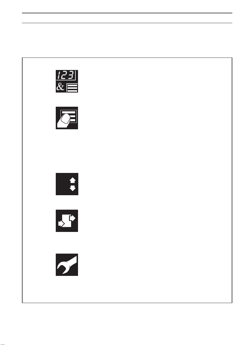
This manual is divided into 5 sections which contain all the information needed to
install, configure, set up and operate the instrument. Each section is identified
clearly by a symbol as shown below.
Displays and Function Keys
• Displays and function keys
• LED Indication
• Error Messages
Operator Mode (Level 1)
• Operator menus for:
– Standard controller
– Heat/Cool controller
– Remote Set Point controller
– Profile controller
– Multiple Fixed Set Points controller
• Auto tuning
Set Up Mode (Levels 2, 3 and 4)
• Level 2 – Tuning
8
• Level 3 – Set Points
• Level 4 – Profile
Configuration Mode (Levels 5 and 6)
• Level 5 – Basic hardware and control
functions
• Level 6 – Ranges and passwords
Installation
• Siting
• Mounting
• Electrical connections
Symbol Identification and Section Contents
1

CONTENTS
1 DISPLAYS AND FUNCTION KEYS ............................................................. 3
1.1 Introduction .......................................................................................... 3
1.2 Use of Function Keys .......................................................................... 4
1.3 LED Alarms and Indicators ................................................................. 5
1.4 Error Messages ................................................................................... 6
2 OPERATOR MODE ...................................................................................... 7
2.1 Introduction .......................................................................................... 7
2.2 Standard Controller .............................................................................8
2.3 Heat/Cool Controller............................................................................9
2.4 Remote Set Point Controller .............................................................10
2.5 Profile Controller ............................................................................... 12
2.6 Multiple Fixed Set Points Controller ................................................. 14
2.7 Auto-tune ........................................................................................... 16
3 SET UP MODE ............................................................................................ 18
3.1 Introduction ........................................................................................ 18
3.2 Tuning (Level 2) ................................................................................ 18
3.3 Set Points (Level 3) ........................................................................... 22
3.4 Profile (Level 4) ................................................................................. 25
4 CONFIGURATION MODE .......................................................................... 28
4.1 Introduction ............................................................................................
4.2 Accessing the Configuration Mode ................................................... 28
4.3 Basic Hardware and Configuration (Level 5) ................................... 30
4.4 Ranges and Passwords (Level 6) ..................................................... 40
5 INSTALLATION .......................................................................................... 43
5.1 Siting .................................................................................................. 43
5.2 Mounting ............................................................................................ 45
5.3 Electrical Connections ...................................................................... 47
5.4 Relays, Arc Suppression and Outputs ............................................. 47
Information.
The fold-out page inside on the back cover of this
manual shows all the frames in the programming
levels. Space is provided on the page for writing the
programmed setting or selection for each frame.
2
1 DISPLAYS AND FUNCTION KEYS
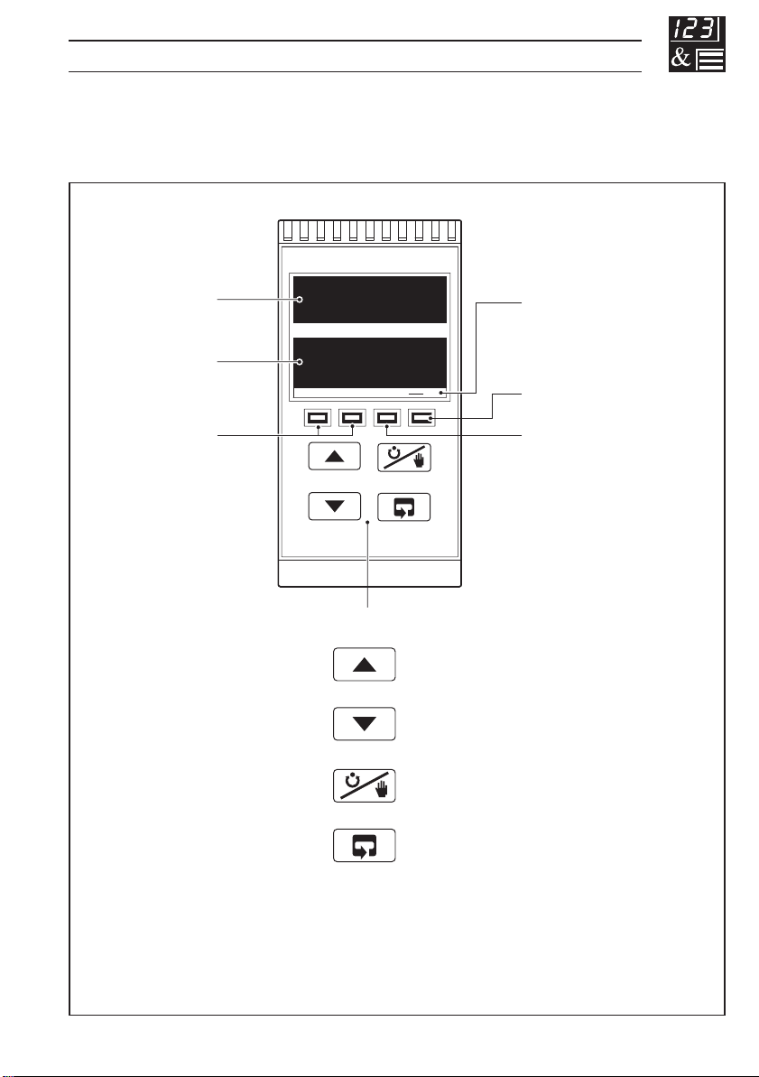
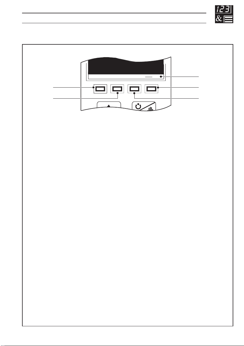
1.1 Introduction – Fig. 1.1
The instrument front panel displays, function keys and LED indicators are shown in
Fig. 1.1.
Upper Display
Lower Display
Alarm LEDs
8888
8888
Function Keys
OP2OP1
MRA1 A2
Raise
Lower
Auto/Manual
Output Value LEDs
(invisible when off)
Manual Control LED
Remote Set Point LED
Parameter Advance
Fig. 1.1 Front Panel Displays, Function Keys and Indicators
3
…1 DISPLAYS AND FUNCTION KEYS
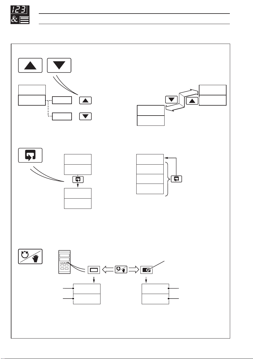
1.2 Use of Function Keys – Fig. 1.2
A – Raise and Lower Keys
bIAS
50.0
51.0
+
LEV1
49.0
–
OPEr
Use to change/set a parameter value… …move between levelsand…
B – Parameter Advance Key
LEV2
tUnE
Frame 1
(top of level)
or…
LEVx
1001
1002
CYCl
Frame 2
1003
5.0
Use to advance to the next
frame within a level…
Note. This key also stores any changes made in the previous frame
C – Auto/Manual Key
Auto
M
…select the top (LEVEL) frame
from within a level
Manual
M
LEV2
tUnE
Press and
hold
Illuminated
Process Variable
Control Set Point
4
125.2
125.8
Use to select Auto or Manual control mode
Fig. 1.2 Use of Function Keys
125.2
70
Process Variable
Control Output (%)
1 DISPLAYS AND FUNCTION KEYS…
1.3 LED Alarms and Indicators
OP2OP1
MRA1 A2
A1
A2
OP1
OP2
M
R
LED Status
All • All LED's flashing – controller is in the Configuration Mode.
A1 • Flashes when Alarm 1 is active (off when inactive).
A2 • Flashes when Alarm 2 is active (off when inactive).
R • On when the controller is operating on the remote set point value.
• Off when the controller is operating using the local set point
value or one of the four fixed set points (in multiple set point mode).
• Flashes when a Ramp/Soak profile is running.
M • On when the controller is operating in Manual control mode.
• Off when the controller is operating in Auto control mode.
• Flashes when the controller is performing an auto-tune.
OP1 • Indicates output 1 (heat) value is displayed in the lower display.
OP2 • Indicates output 2 (cool) value is displayed in the lower display.
Fig. 1.3 LED Alarms and Indicators
5
…1 DISPLAYS AND FUNCTION KEYS
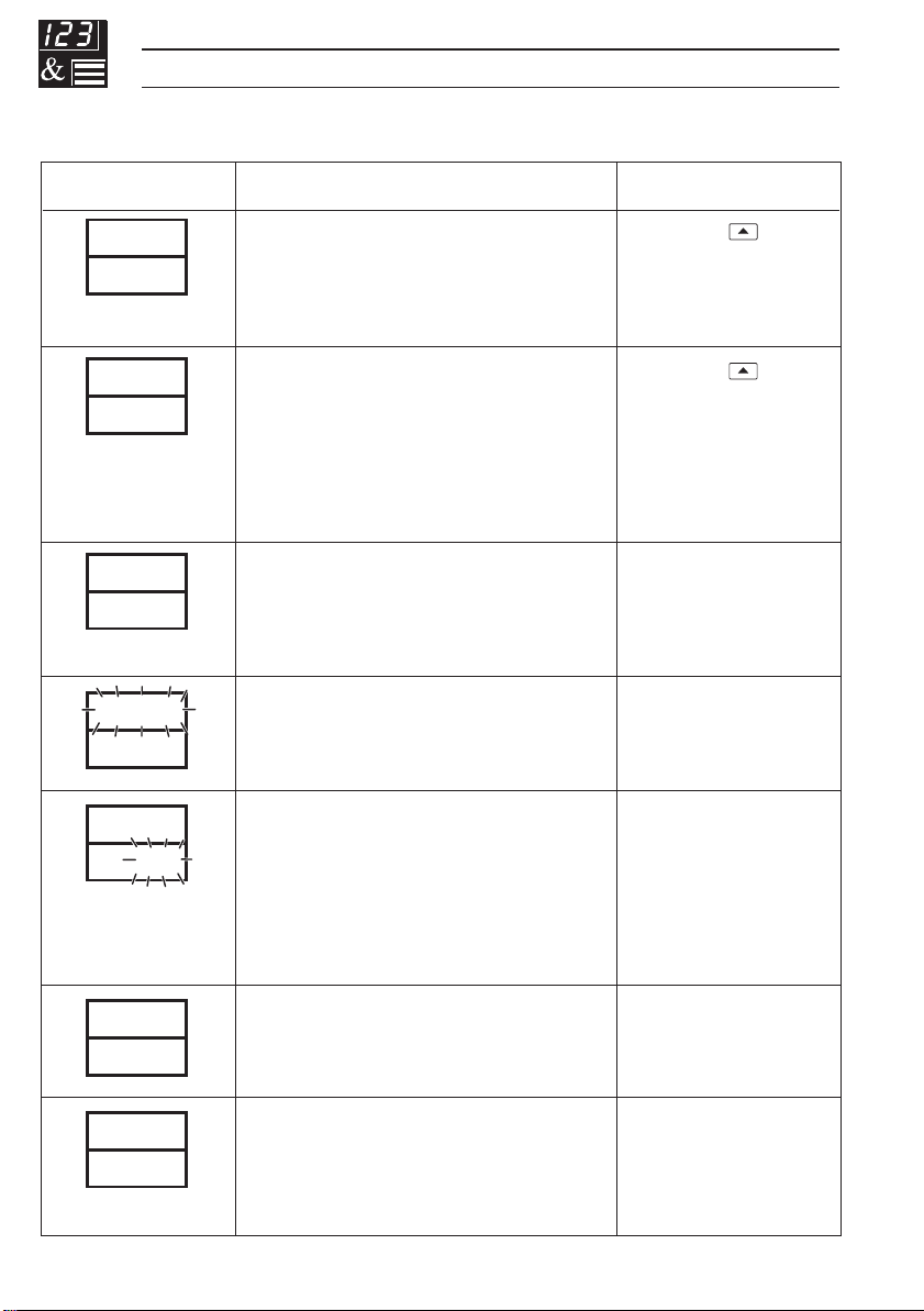
1.4 Error Messages
Display Error/Action
CAL
Err
CnFG
Err
A-d
Err
9999
Calibration error
Turn power off and on again (if the
error persists contact the Supplier).
Configuration error
The configuration and/or setup data
for the instrument is corrupted.
Turn power off and on again (if the
error persists, check configuration/
setup settings).
A to D Converter Fault
The analog to digital converter is
not communicating correctly.
Process Variable Over/Under
Range
70
125.2
70
Remote Set Point Over/Under
Range
The remote set point value is over
or under range. Flashing stops
automatically when the remote set
point input comes back into range.
To Clear Display
Press the
Press the
Turn power off and on
again, if the problem
persists contact the
Supplier
Restore valid input
Select the local set
(rSP.n) in
point
the Operating Page
or the Set Points
Level
key
key
6
OPtn
Err
t.Err
1
Option error
Communications to the option
board have failed.
Auto-tune error
The number displayed indicates the
type of error present – see Table 2.1
in Section 2.7.
Contact the Supplier
Press any key

2 OPERATOR MODE
2.1 Introduction
Operator Mode (Level 1) is the normal day-to-day mode of the instrument.
Frames displayed in level 1 are determined by the control strategy which is
selected during configuration of the instrument – see Section 4.
Note. Only the operating frames relevant to the configured strategy are
displayed in Operator Mode.
The five control strategies are:
• Standard controller – page 8
• Heat/Cool controller – page 9
• Remote Set Point controller – page 10
• Profile controller – page 12
• Multiple Fixed Set Points controller – page 14
7
…2 OPERATOR MODE
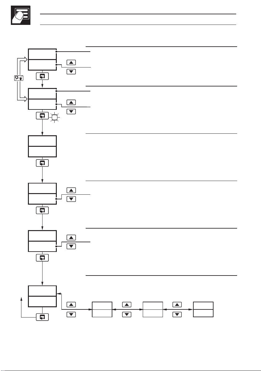
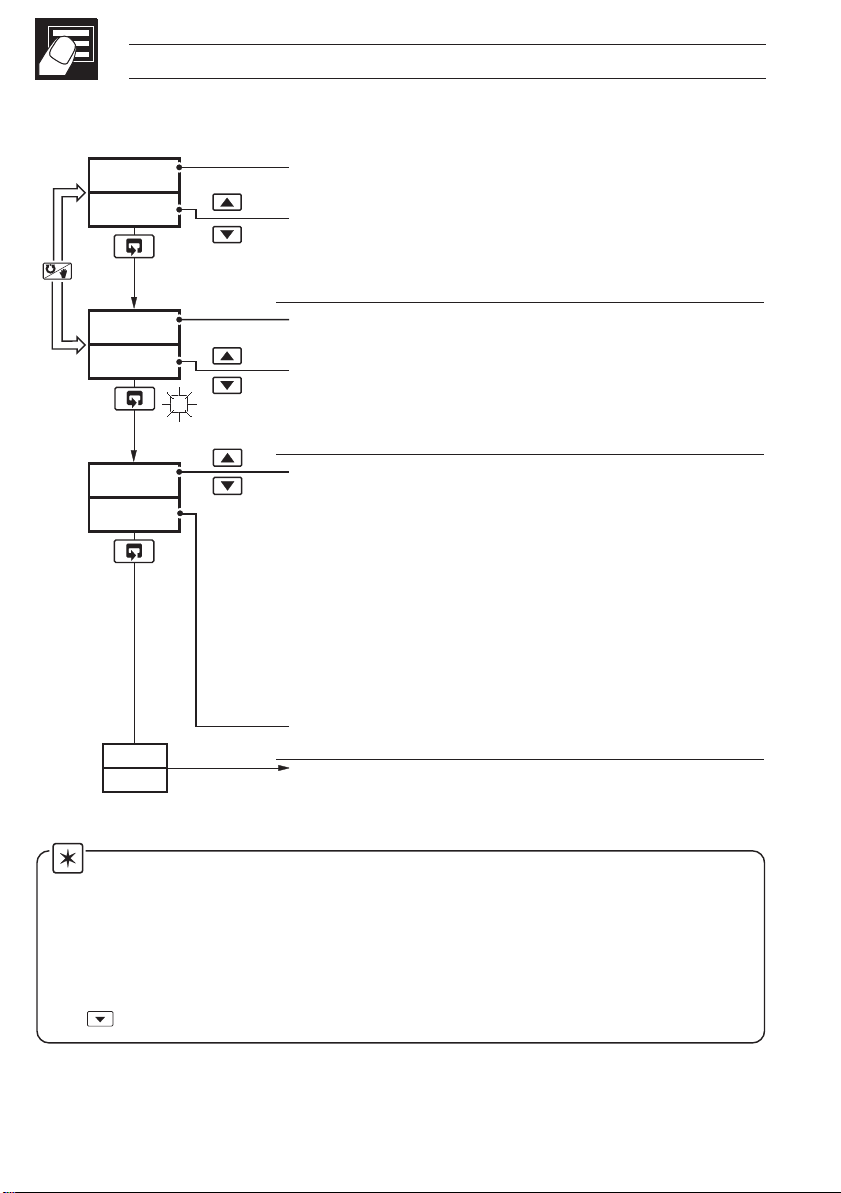
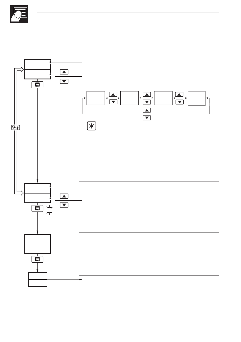
2.2 Standard Controller
Auto
Man
•1
125.2
125.8
125.2
70
SPrP
120.5
CodE
0
OP1
Process Variable Value
Control Set Point Value (Local set point)
[Set point low limit to set point high limit]
Process Variable Value
Control Output Value (%)
[0 to 100% (–10% to 110% for analog output)]
Adjustable in manual mode only.
Ramping Set Point Value (Read only)
The actual set point value is displayed, i.e. the
instantaneous value the controller is working to.
Security Code
[0 to 9999]
Select the appropriate security code to access:
Auto-tune enable frame (Level 1),
Set Up mode (Levels 2, 3, 4).
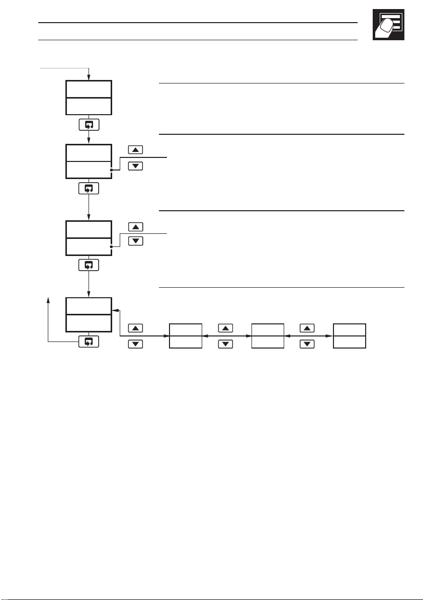
AtnE
OFF
LEV1
OPEr
•1 Not displayed if the ramping set point facility is turned off – refer to
Section 3.3.
8
Auto-tune Enable
ON – Auto-tune on
OFF – Auto-tune off
Refer to page 16 for the Auto-tune procedure.
Level 1 (Operator mode)
Refer to Section 3 for levels 2, 3 and 4.
LEV2
LEV3
SEtPtUnE
LEV4
PrFL
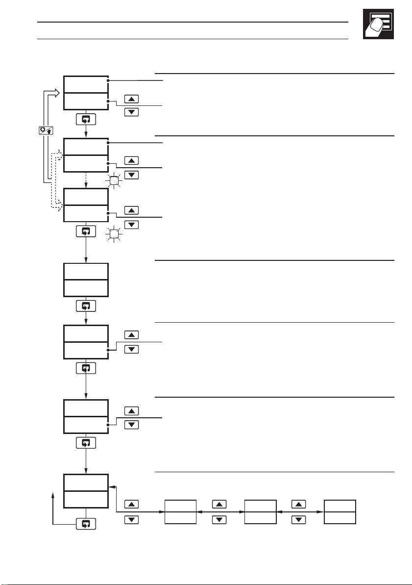
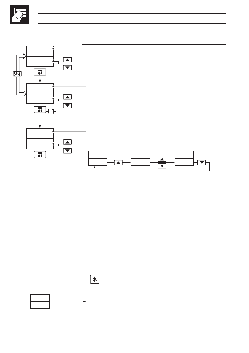
2.3 Heat/Cool Controller
2 OPERATOR MODE…
Auto
Man
•1
125.2
125.8
125.2
70
125.2
-30
SPrP
120.5
COdE
0
OP1 (Heat)
OP2 (Cool)
Process Variable Value
Control Set Point Value (Local set point)
[Set point low limit to set point high limit]
Process Variable Value
Control Output Value (Heat %)
[0% to 100% (0% to 110% for analog output)]
If adjusted below 0% the 'Cool' frame is displayed.
Control Output 2 Value (Cool %)
[0% to –100% (0% to –110% for analog output)]
If adjusted above 0% the 'Heat' frame is displayed.
Ramping Set Point Value (Read only)
The actual set point value is displayed i.e. the
instantaneous value the controller is working to.
Security Code
[0 to 9999]
Select the appropriate security code to access:
Auto-tune enable frame (Level 1),
Set Up mode (Levels 2, 3, 4).
AtNE
Auto-tune Enable
ON – Auto-tune on
OFF
LEV1
OPEr
•1 Not displayed if the ramping set point facility is turned off – refer to
Section 3.3.
OFF – Auto-tune off
Refer to page 16 for the Auto-tune procedure.
Level 1 (Operator mode)
See Section 3 for levels 2, 3 and 4.
LEV2
LEV3
SEtPtUnE
LEV4
PrFL
9
…2 OPERATOR MODE
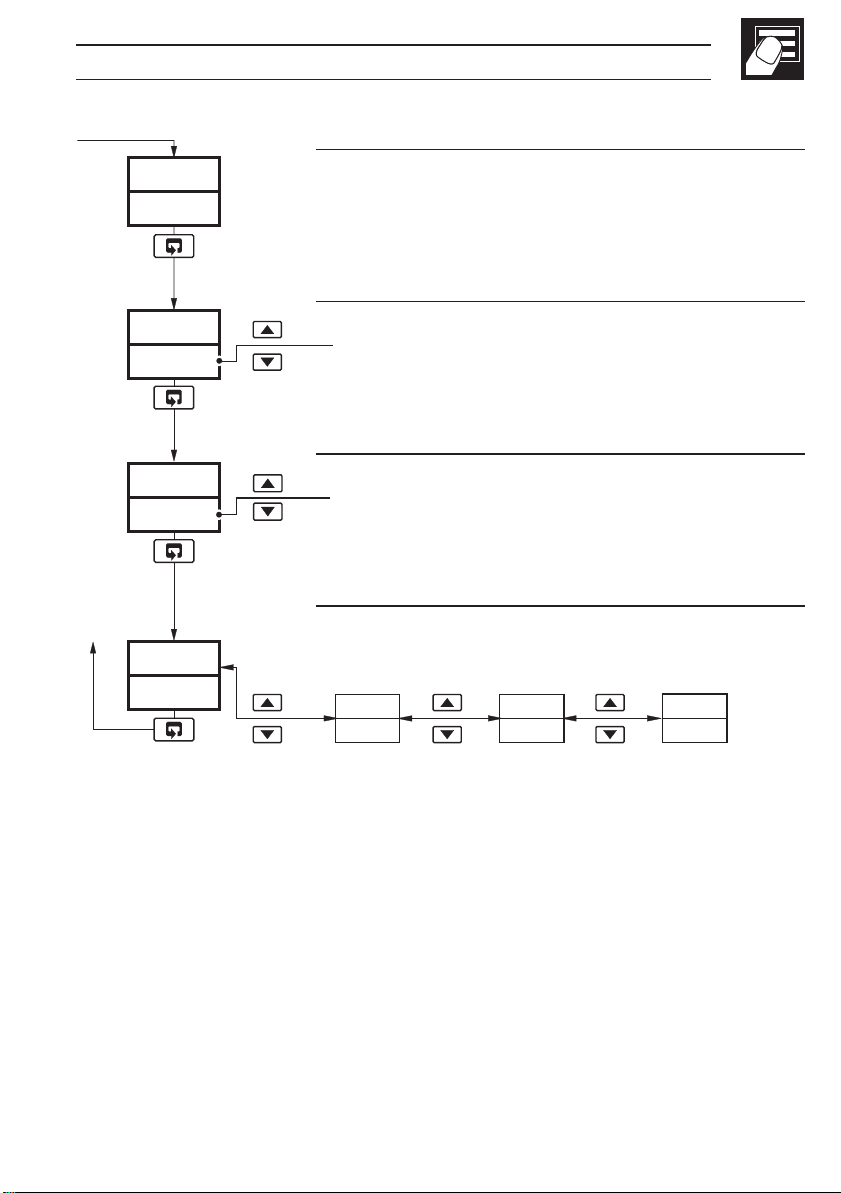
2.4 Remote Set Point Controller
Auto
Man
125.2
125.8
125.2
70
rSPn
rSPn
123.4
123.4
SPrP
120.5
OP1
Process Variable Value
Control Set Point Value
[Set point low to set point high limit]
Adjustable in local Set Point Mode only.
Process Variable Value
Control Output Value (%)
[0% to 100% (–10% to 110% for analog output)]
Adjustable in manual mode only.
Remote Set Point Selection
rSPY – Remote Set Point
rSPn – Local Set Point
Local or remote set point can also be selected using
a digital input.
The option to change the set point selection at this
frame can be disabled in the configuration level.
Remote Set Point Value (Read only)
Continued on next page…
Note.
If the remote set point input fails while selected, the controller automatically
selects the local set point value. The upper display changes to
lower display flashes. When the fault condition is removed, the remote set point
is re-selected automatically. To clear the error condition while the remote set
point input is still outside its allowed range, select the local set point by pressing
the
10
key (rSP.n is displayed).
rSP.F and the
…2.4 Remote Set Point Controller
•1
SPrP
120.5
CodE
0
AtnE
OFF
LEV1
OPEr
Ramping Set Point Value (Read only)
The actual set point value is displayed, i.e. the
instantaneous value the controller is working to.
Security Code
[0 to 9999]
Select the appropriate security code to access:
Auto-tune enable frame (Level 1),
Set Up mode (Levels 2, 3, 4).
Auto-tune Enable
ON – Auto-tune on
OFF – Auto-tune off
Refer to page 16 for the Auto-tune procedure.
Level 1 (Operator mode)
See Section 3 for levels 2, 3 and 4.
LEV2
2 OPERATOR MODE…
LEV3
SEtPtUnE
LEV4
PrFL
•1 Not displayed if the ramping set point facility is turned off – refer to
Section 3.3.
11
…2 OPERATOR MODE
2.5 Profile Controller
Auto
Man
125.2
125.8
125.2
70
SG 1
StOP
OP1
Process Variable Value
Control Set Point Value
[Set point low limit to set point high limit]
Process Variable Value
Control Output Value (%)
[0% to 100% (–10% to 110% for analog output)]
Adjustable in manual mode only.
Profile Segment Number (1 to 4) currently active
Profile Status
SG 1
StOP
SG 1
rUN
SG 1
HOLd
StOP – Profile inactive – the control set point
is equal to the local set point value
when the profile is not running.
rUN – Profile active – currently operating on
the segment indicated.
HOLd – Profile hold – pauses the current ramp
or soak mode by putting it into 'Hold'
mode. The guaranteed ramp soak
feature can also be used to put the profile
into a 'Hold' mode until the process
variable comes back within the
hysteresis band.
12
SPrP
120.5
Note. The profile status can be changed using
a digital input.
Continued on next page…
…2.5 Profile Controller
2 OPERATOR MODE…
•1
SPrP
120.5
CodE
0
AtnE
OFF
LEV1
OPEr
Ramping Set Point Value (Read only)
The actual set point value is displayed, i.e. the
instantaneous value the controller is working to.
Security Code
[0 to 9999]
Select the appropriate security code to access:
Auto-tune enable frame (Level 1),
Set Up mode (Levels 2, 3, 4).
Auto-tune Enable
ON – Auto-tune on
OFF – Auto-tune off
Refer to page 16 for the Auto-tune procedure.
Level 1 (Operator mode)
See Section 3 for levels 2, 3 and 4.
LEV2
LEV3
SEtPtUnE
LEV4
PrFL
•1 Not displayed if the ramping set point facility is turned off – refer to
Section 3.3.
13
…2 OPERATOR MODE
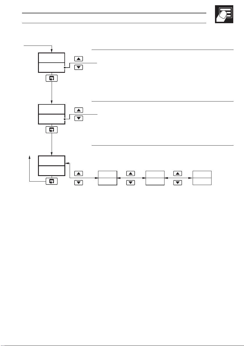
2.6 Multiple Fixed Set Points Controller
If the Multiple Fixed Set Points Controller type is selected during configuration, four
fixed control set points can be set – see Section 4.4.
Auto
Man
125.2
125.8
125.2
70
OP1
Process Variable Value
Fixed Control Set Point Selected
SP-1
100.3
Notes.
a) The top display momentarily displays the set
point selected before reverting to the display
of the process variable value.
b) A digital input can also be used to select the
fixed set points.
Process Variable Value
Control Output Value (%)
[0% to 100% (–10% to 110% for analog output)]
Adjustable in manual mode only.
SP-2
200.1
SP-3
300.2
SP-4
400.5
•1
SPrP
12.05
Ramping Set Point Value (Read only)
The actual set point value is displayed, i.e. the
instantaneous value the controller is working to.
CodE
0
•1 Not displayed if the ramping set point facility is turned off – refer to
Section 3.3.
14
Continued on next page…
2 OPERATOR MODE…
…2.6 Multiple Fixed Set Points Controller
CodE
0
AtnE
OFF
LEV1
OPEr
Security Code
[0 to 9999]
Select the appropriate security code to access:
Auto-tune enable frame (Level 1),
Set Up Mode (Levels 2, 3, 4).
Auto-tune Enable
ON – Auto-tune on
OFF – Auto-tune off
Refer to page 16 for the Auto-tune procedure.
Level 1 (Operator mode)
See Section 3 for Levels 2, 3 and 4.
LEV2
LEV3
SEtPtUnE
LEV4
PrFL
15
 Loading...