

Page 1
User’s Guide
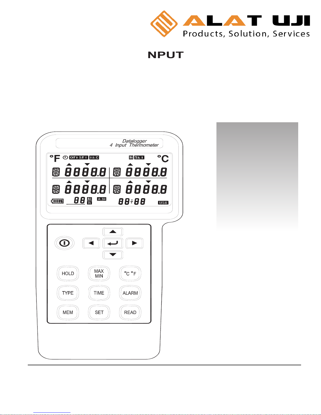
DATALOGGER 4 INPUT
THERMOMETER
HH1384
I
N
STRUC
TIO
N
MANUAL
M AX
M IN
A
L
AR
M
-
I
N
TV
m :s
d-h
FU LL
NO
.
T
4
T
3
T
2
T
1
Office: Jl. Radin Inten II No. 62 Duren Sawit, Jakarta 13440 - Indonesia
Workshop: Jl. Pahlawan Revolusi No. 22B, Jakarta 13430 - Indonesia
Phone: 021-8690 6777 (Hunting)
Fax: 021-8690 6777
Mobile: +62 816 1740 8925
Fax: 021-8690 6771
Page 2
1. INTRODUCTION: FEATURES
This
instrument
is
a digit
a
l
4 input
thermometer
and
da
ta
logger
that
work
s wi
th
an
y
K,
J,
E,
T,
R, S, N, L,
U,
B
and C-type
thermocouple temperature sensor.
Te
mperature indication follows the
international temperature
scale
of
1990
(
ITS-90).
Read the
follo
w
ing
safety
information
carefully
before
attempting
to
operate
the
meter.
Use
the
meter
onl
y
as specified
in
this
man
u
al;
otherwi
se,
the
protection provided by the meter may be impaired.
E
n
vironment
conditions
Altitude up to 2000 meters
Relati
v
e
l
y humi
di
ty 80% max.
Operation Am
bient
0~50
°C(
32°F
~12
2
°F)
Features
Isolated Input Protection
of
350Vp-p between any
t
wo inpu
t
s.
High
l
y
accura
te thermome
ter
w
i
th
thermocoupl
e
K
,
J,
E,
T,
R
,
S, N
,
L, U, B, C t
y
pes.
4
input
function
T1/
T2
/T
3
/T
4
temperature displa
y
.
Programma
ble
Hi –
Lo
alarm for
4
inpu
ts.
Disp
lay
of MAX,
MIN
and
MAX–MIN values of 4
inpu
t
s.
Independent
Input Setup (type of thermocouple,
Hi – Lo alarm values).
Memory and Read function (99 sets)
512KB auto datalogging capacity.
USB interface.
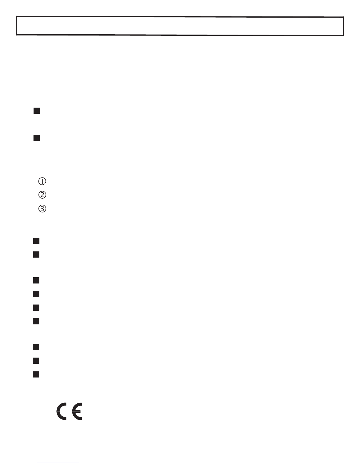
Safety symbols
Comply with EMC
~ 1 ~
Page 3

2. SPECIFICATIONS
2-1 Electronical Specifications
°C °F
Type
Range Accuracy Range Accuracy
K
-200 ~ -150
-150 ~ -100
-100 ~ 999.9
1000 ~ 1370
±3.0°C
±2.0°C
±0.05% ±1.0°C
±0.2% ±1.0°C
-328 ~ -238
-238 ~ -148
-148 ~ 999.9
1000 ~ 2498
±5.4°F
±3.6°F
±0.05% ±1.8°F
±0.2% ±1.8°F
J
-200 ~ -100
-100 ~ 100
100 ~ 999.9
±2.5°C
±1.5°C
±0.05% ±1.0°C
-328 ~ -148
-148 ~ 212
212 ~ 999.9
1000 ~ 1832
±4.5°F
±2.7°F
±0.05% ±1.8°F
±0.2% ±1°F
E
-150 ~ -100
-100 ~ 760
±3.0°C
±0.05% ±1.0°C
-238 ~ -148
-148 ~ 999.9
1000 ~ 1400
±5.4°F
±0.05% ±1.8°F
±0.2% ±1°F
T
-200 ~ -150
-150 ~ -100
-100 ~ 400
±3.0°C
±0.15% ±2.5°C
±0.1% ±1.0°C
-328 ~ -238
-238 ~ -148
-148 ~ 752
±5.4°F
±0.15% ±4.5°F
±0.1% ±1.8°F
R/S
0 ~ 100
100 ~ 300
300 ~ 999.9
1000 ~ 1600
±5.0°C
±3.0°C
±0.05% ±2.0°C
±0.25% ±2.0°C
32 ~ 212
212 ~ 572
572 ~ 999.9
1000 ~ 2912
±9.0°F
±5.4°F
±0.05% ±3.6°F
±0.25% ±3.6°F
N
0 ~ 999.9
1000 ~ 1300
±0.1% ±1.0°C
±0.2% ±1.0°C
32 ~ 999.9
1000 ~ 2372
±0.1% ±1.8°F
±0.2% ±1.8°F
L
-200 ~ 900 ±0.1% ±1.0°C
-328 ~ 999.9
1000 ~ 1652
±0.1 % ±1.8°F
±0.2% ±1°F
U
0 ~ 600 ±0.1% ±1.0°C
32 ~ 999.9
1000 ~ 1112
±0.1% ±1.8°F
±0.2% ±1°F
B
600 ~ 999.9
1000 ~ 1760
±0.05% ±2.0°C
±0.1% ±2.0°C
1112 ~ 1831
1832 ~ 3200
±0.05% ±3.6°F
±0.1% ±3.6°F
C
0 ~ 999.9
1000 ~ 1760
±0.1% ±1.5°C
±0.2% ±1.5°C
32 ~ 999.9
1000 ~ 3200
±0.1% ±2.7°F
±0.2% ±2.7°F
~ 2 ~
Page 4

NOTE
This basic accuracy specification does not include the error of
the temperature probe. Please refer to the temperature probe
accuracy specification for additional details.
Temperature Coefficient:
0.01% of reading +0.1°C per °C (0.2°F per °F)
outside the specified +18°C to 28°C (+64°F to 82°F) range.
Isolated Input Protection between any Two Inputs : 350Vp-p
Manual Data Memory Capacity: 99 sets.
Continuity Data Logging Capacity: 36,000 sets.
2-2 General Specifications
Power Supply: 6 pcs size AA battery or DC 9V AC adaptor.
Battery Life: approx. 55 hours (Alkaline battery)
Auto Power Off: 5, 15 or 30 minutes (If no key is pressed).
Low Battery Indicator: The (
) is displayed when the
battery voltage drops below the operating voltage.
Measurement Rate : One time per 2 seconds.
Weight : 405g / 14.3oz (batteries included)
Dimension : 18.7(L) × 7.3(W) × 5.3(T) cm
7.3”(L) × 2.9”(W) × 2.1”(T)
Operating Temperature: 0 to 50℃ (32 to 122℉)
and Humidity: Below 80% RH.
Storage Temperature: -10 to 60℃, 14 to 140℉
and Humidity: Below 70% RH.
Accessories: Instruction manual, alkaline batteries, USB cable,
software CD, carrying case and K-type
thermocouples (1 per channel).
~ 3 ~
Page 5
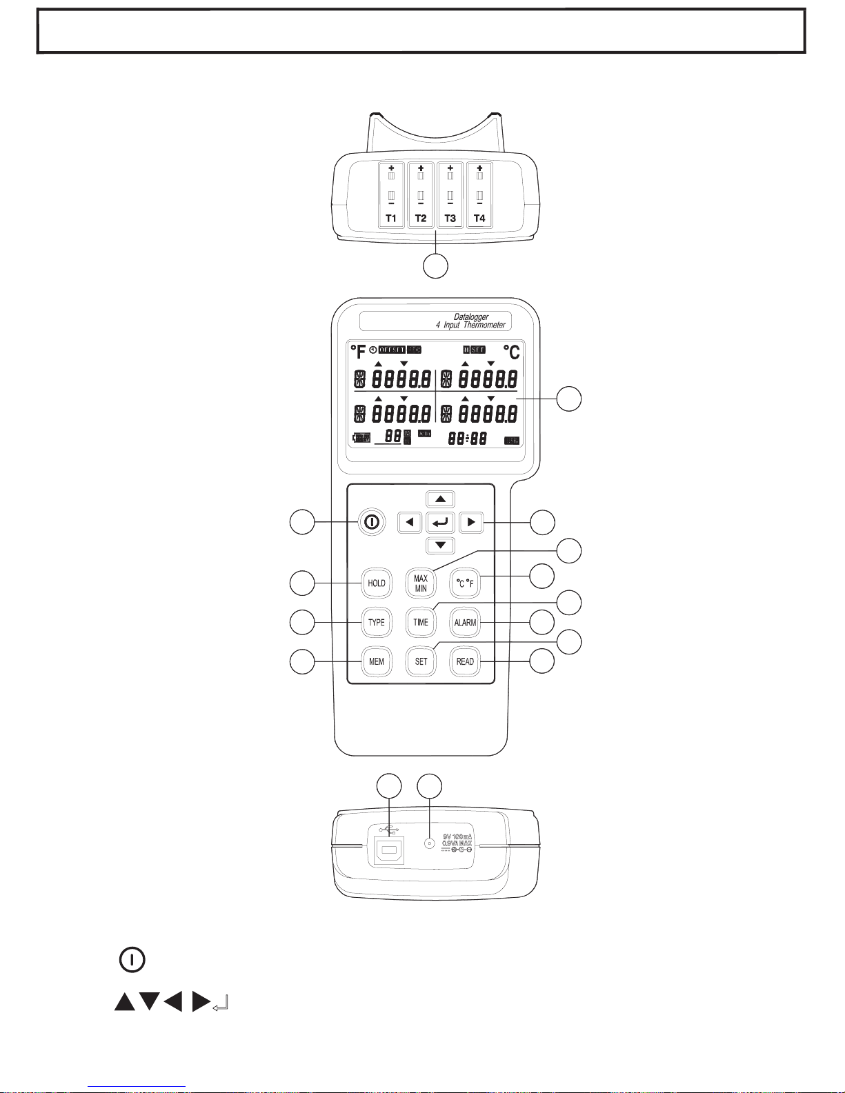
3. PARTS & CONTROLS
3-1 Description of Parts & Control keys
8
MAX MIN
ALARM
-
INTV
m:s
d-h
FULL
NO.
T 4
T 3
T 2
T 1
5
13
10
11
7
4
3
6
15
14
12
9
2
1
(1). LCD Display
(2).
Key : Power on – off control key.
(3).
Keys
: Setting keys.
(4). HOLD Key:
~ 4 ~
Page 6

Data hold function key, press “HOLD” key to hold data, the
“ H ” symbol is displayed, press this key again to exit this
function.
Press and hold down “HOLD” key then press " " key to
turn on the meter, the “
” symbol disappear, exit auto
power off function.
(5). MAX MIN Key: Press “MAX MIN” key to circulate the
reading of Maximum, Minimum, Maximum minus
Minimum, and Current. Press this key for 2 seconds to
exit this mode.
(6). °C / °F Key: Press “°C / °F” key to switch the units
between Celsius (°C) and Fahrenheit (°F).
(7). TYPE Key: Press "TYPE" key to enter the thermocouple
type select mode, press this key again to exit this mode.
(8). TIME Key: Press “TIME” key to circulate display data and
time.
(9). ALARM Key: Press “ALARM” key to enable or disable
Alarm function.
(10). MEM Key: Manual data memory control key.
(11). SET Key: Press “SET” key to
start or exit setup.
(12). READ Key: Manual memory data reading control key.
(13). T1, T2, T3, T4 : Thermocouple T1, T2, T3 and T4 inputs.
(14). USB Interface Jack.
(15). AC Adaptor Input Jack.
3-2 Description of Display
MAX MIN
ALARM
-
INTV
m:s
d-h
FULL
NO.
T 4
T 3
T 2T 1
~ 5 ~
Page 7

°F, °C : Temperature units.
: Auto power off indication.
OFFSET : The thermocouple measurement includes an offset
indication.
REC : MAX MIN Recording mode and current reading indication.
REC MAX : Maximum reading indication.
REC MIN : Minimum reading indication.
REC MAX-MIN : Maximum minus Minimum value indication.
H : Data hold function indication.
SET : Setting mode indication.
: Thermocouple type indication.
ALARM : Alarm mode indication.
ALARM
: Input temperature exceeds the high limit value
indication.
ALARM : Input temperature is below the low limit value
indication.
T1, T2, T3, T4 : Thermocouple T1, T2, T3, T4 input temperature
measurement display.
: Battery capacity indication.
: Replace batteries indication.
NO.
: Last manual data memory address number indication (01–99).
M : Manual data memory indication, M displays one time store one
sets data into the memory.
NO.
R : Manual data memory read address number indication,
the memory data displayed for read.
A-M : Auto data logging indication, A-M will disappear after storing
the data.
INTV : Auto data log interval time setting indication.
~ 6 ~
Page 8

Full : Auto data logged memory full indication, if exceeds 255
memory blocks, total maximum record capacity size is
36,000 sets of data for 4 input thermocouple temperature
measurement (100,000 sets data for 1 input record).
m:s
: Time display indication.
4. OPERATION INSTRUCTION
WARNING
Before using the meter inspect the case. Do not use the
meter if it appears damaged. Look for cracks or missing
plastic. Pay particular attention to the insulation around the
connectors.
Disconnect thermocouples from the meter before opening the
case.
Replace the batteries as soon as the battery indicator “
”
appears. The possibility of false reading can lead to personal
injury.
Do not use the meter if it operates abnormally. Protection
may be impaired.
Do not operate the meter around explosive gas, vapor or dust.
Do not use the meter with any part of the case or cover
removed.
4-1 Setting the meter
1. Real – Time setting:
(a). Press "
" key to turn on the meter.
(b). Press “SET” key to enter the setting mode, the “Set clock”
and “ SET ” symbols are displayed.
(c). Press "
" key to enter real time setting mode and the two
flicking numbers of year.
(d). Press
or
key to set the year (real time).
~ 7 ~
Page 9

(e). Press "
" key and move to the two flicking digits of month.
(f). Press
or
key to set month (real time).
(g). Press "
" key and move to the two flicking digits of day.
(h). Press
or
key to set day (real time).
(i). Press "
" key and move to the two flicking digits of hour.
(j). Press
or
key to set hour (real time).
(k). Press "
" key and move to the two flicking digits of
minutes.
(l). Press
or
key to set minutes (real time).
(m). Press "
" key and move to the two flicking digits of second.
(n). Press
or
key to set seconds (real time).
(o). Press "
" key to store real time values.
(r). Press “SET” key to exit this mode.
2. Interval – Time setting :
The logging interval time determines how often the meter stores
logged readings in memory.
(a). Press "
" key to turn on the meter.
(b). Press “SET” key to enter the setting mode, then press
or
key until the display shows “Set Intr”.
(c). Press "
" key to enter the interval time setting mode and the
three flicking numbers of second.
(d). Press
or
key to set the desired second of interval time
(1 to 255 seconds).
(e). Press "
" key to store the auto datalogging interval time.
(f). Press “SET” key to exit this mode.
3. Offset setting :
You can adjust the meter readings to compensate for the errors
of a specific thermocouple. The allowable adjustment range is
from +12.7 to -12.8 degree, regardless of the temperature units.
You can store individual offsets for T1, T2, T3 and T4.
(a). Press "
" key to turn on the meter.
(b). Press “SET” key to enter the setting mode, then press
or
key until the display shows “SEt OFSEt”.
~ 8 ~
Page 10

(c). Press "
" key to enter the offset setting mode, the
“ OFFSET ” symbol is displayed.
(d). Press
or
key to select the desired T1, T2, T3 or T4.
(e). Press
or
key to set the desired offset values.
(f).. Press "
" key to store the offset value.
(g). Press “SET” key to exit this mode.
The temperature measurement plus the offset appears in the
display. Remember to set the offset to 0.0 when it is no longer
needed. The “ OFFSET ” symbol will disappear when the offset
values all are 0.0.
4. Auto Power Off Time setting :
(a). Press "
" key to turn on the meter.
(b). Press “SET” key to enter the setting mode, then press
or
key until the display shows “SEt SLEEP”.
(c). Press "
" key to enter the auto power off time setting mode,
the “SLEEP” symbol is displayed.
(d). Press
or
key to choose the desired auto power off
time. The choices are: 5, 15 and 30 minutes.
(e). Press "
" key to store the choice.
(f). Press “SET” key to exit this mode.
5. Alarm High / Low Limit setting :
(a). Press "
" key to turn on the meter.
(b). Press “SET” key to enter the setting mode, then press
or
key until the display shows “SEt ALArn”.
(c). Press "
" key to enter the alarm high limit and low limit
setting mode, the “ ALARM ” symbol is displayed.
(d). Press
or
key to select the desired T1, T2, T3 or T4.
(e). Press "
" key to enter the high limit value setting, the “
”
symbol is displayed.
(f). Press
or
key to set the desired alarm high limit value,
the resolution of setting value is 0.1 degree, regardless of
the temperature units.
-9-
Page 11

(g). Press "
" key to store the alarm high limit value and to enter
the alarm low limit value setting, the symbol “
” is displayed.
(h). Press
or
key to set the desired alarm low limit value, the
resolution of setting value is 0.1 degree, regardless of the
temperature units.
(i). Press "
" key to store alarm low limit value. You can store
individual alarm High / Low limit values for T1, T2, T3 and T4,
by repeating (c) to (i) procedure.
(j). Press “SET” key to exit this mode.
(k). Press “ALARM” key to enter the alarm function, the
“ALARM” symbol is displayed. When the measured
temperature value exceeds the setting High temperature
value (the “
” symbol will flicker the display) or below the
setting Low temperature value (the “
” symbol will flicking
display.) the beep will sound one time per 4 seconds.
(l). Press “ALARM” key again to exit the alarm function.
4-2 Setting the Thermocouple Type
1. Press "
" key to turn on the meter.
2. Press “TYPE” key to enter the thermocouple type choices.
The currently selected thermocouple type blinks.
3. Press
or
key to select the desired T1, T2, T3 or T4.
4. Press
or
key until the thermocouple type you want
appears on the display.
5. Press "
" key to store the thermocouple type. You can
store individual thermocouple types for T1, T2, T3 and T4, by
repeated (3) to (5) procedure.
6. Press “TYPE” key again to exit this choices.
4-3 Temperature Measurement
1. Press "
" key to turn on the thermometer.
2. Plug the thermocouple (s) into the thermocouple input. If no
thermocouple is plugged into the selected input or the
thermocouple is "open", the display will show "- - -".
~ 10 ~
Page 12

3. Press "°C / °F" key to desired temperature scale.
4. Perform measurements by contacting the object being
measured with the probe sensor.
5. Read the temperature on the display. The display shows
“OL” (overload) or “Un” (under ranges) when the
temperature being measured is outside the meter valid
range.
4-4 Maximum (MAX), Minimum (MIN) Recording
Measurement
1. Press “MAX MIN” key to enter the recording mode, the “ REC ”
symbol is displayed.
2. Press “MAX MIN” key to circulate the display of the maximum
(REC MAX), minimum (REC MIN), maximum minus minimum
(REC MAX-MIN) and current REC) reading.
3. Press “HOLD” key to paused recording, the “H” symbol is
displayed, press “HOLD” key again will resume recording.
4. Press “MAX MIN” key for 2 seconds to exit this mode.
4-5 Manual Data Memory and Read Function Operation
1. Clear the manual memorized data
(a). Press "
" key to turn off the meter.
(b). Press and hold down “MEM” key, then press "
" key again to
turn on the meter, the “CLr YES no M” symbol is displayed.
(c). Press or
key to select “YES” symbol is displayed
flicking.
(d). Press "
" key to clear the manual memorized data.
(e). Press "
" key again to exit this mode.
2. Store manual data to memory
(a). Pressing “MEM” key one time will store one set of
measured data to memory. The “M” symbol will disappear
and the stored memory address will displayed.
(b). Maximum store memory capacity size is 99 sets.
~ 11 ~
Page 13

3. Read the manual store data
(a). Press “READ” key to enter the read mode, the “R” symbol
is displayed.
(b). Press
or
key to read the memories data, the
memories data address will be displayed.
(c). Press “READ” key again to exit this mode.
4-6 Auto Datalogging Function Operation
1. Clear the Auto datalogged data :
Before entering into the clear memory data mode, users must
down load the previous memory data to PC.
(a). Press "
" key to turn off the meter.
(b). Press and hold down “
MEM
” key, then press "
" key again
to turn on the meter, the “
CLr YES no M
” symbol is
displayed.
(c). Press "
" key to enter the clear auto datalogged data
mode, the “CLr YES no AM” symbol is displayed.
(d). Press
or
key to select “YES” symbol is displayed
flickering
(e). Press "
" key to clear the auto datalogged data and exit
this mode.
2. Store Auto datalogging data to memory :
(a). Press “MEM” key for 3 seconds to start auto datalogging,
the “A-M” symbol is displayed, the “A-M” symbol
according to the interval time will disappear after storing
one set of data into the memory.
(b). Press “MEM” key for 3 seconds to stop data record, the
current block number will be displayed for one second.
Press “MEM” key for 3 seconds will resume data record,
but maximum is divided to 255 memory blocks. Total
maximum record capacity size is 36,000 sets data for 4
-12-
Page 14

(b). input thermocouple temperature measurement (100,000
sets data for 1 input record).
(c). When maximum block or maximum capacity is full, the
“FULL” symbol will be displayed, the data record is auto
stopped.
3. Download data to PC :
Please refer to the software manual (CD-ROM) to download
the data.
4-7 Disable Auto Power off Function
The meter will automatically enter sleep mode approx. 5, 15 or
30 minutes decided by user setting to save power
consumption.
1. Disable auto power off procedure :
(a). Press "
" key to turn off the meter.
(b). Press and hold down "HOLD" key then press "
" key to
turn on the meter, the auto power off function will be
disabled, and the auto power off symbol “
” will
disappear.
2. Auto power off mode is enabled each time you turn on the
meter and is automatically disabled bt the follow modes :
(a). MAX MIN record mode.
(b). Auto datalogging function is active.
(c). PC linked.
5. MAINTENANCE
5-1 General Maintenance
1. Clean the meter and accessories with a damp cloth and a mild
soap. Do not use abrasives, solvent or alcohol.
~ 13 ~
Page 15

5-
2
Battery Replacem
e
nt :
WARN
I
N
G
To AV
OID
el
ectrical
sh
ock,
remove
any inputs before
replacing the batteries.
1. W
hen
op
erating
t
h
e
meter on
batt
e
rie
s, perio
dically
check the
ba
tter
y
sy
m
bo
l
to
d
e
t
e
rm
ine
the
remaining
batt
e
ry capac
it
y
.
T
he
number
of
blac
k segme
nts
de
c
rea
se
s as t
h
e
b
a
tt
eries
are
used
u
p.
W
h
en
t
h
e “
”
s
y
mbol
displ
a
y
st
arts
to flash,
correct meas
u
rement is no l
onger
possibl
e
. Replac
e
th
e
ba
t
teries with a fresh
set.
2. Take care not to reverse the (+) and (-) polarity when inserting
t
he
ba
tt
eries
.
Alwa
y
s
r
eplace
all
six
b
atter
ie
s
t
oget
her
.
Do
not m
ix
old a
n
d new b
a
tt
e
ries or batteries of diffe
re
nt type.
R
e
move th
e
b
a
tt
eries
f
r
om the meter,
if the
mete
r
i
s not
t
o
b
e
used for
a
mont
h
or longer.
6. USB
I
NTERF
ACE,
SOFTWARE INS
T
ALL
A
TION
AND
OPERATION
For
the
de
taile
d instruction
,
please
refer
t
o
the content of
attached CD-ROM, which has the complete instruction of
software operation and relevant information.
Protocol : are enclosed within the content of CD-ROM,
please open the CD-ROM for details.
※ All rights reserved.
※ Do not reproduce without authorization.
 Loading...