

Page 1
omega.com
e-mail: info@omega.com
For latest product manuals:
omegamanual.info
FTB600B Series
Ultra-Low Flow Sensors
Shop online at
User’s Guide
Page 2

OMEGAnet®On-Line Service Internet e-mail
omega.com info@omega.com
It is the policy of OMEGA Engineering, Inc. to comply with all worldwide safety and EMC/EMI regulations that apply. OMEGA is constantly pursuing
certification of its products to the European New Approach Directives. OMEGA will add the CE mark to every appropriate device upon certification.
The information contained in this document is believed to be correct, but OMEGA accepts no liability for any errors it contains,and
reserves the right to alter specifications without notice.
WARNING: These products are not designed for use in, and should not be used for, human applications.
Benelux:
Postbus 8034, 1180 LA Amstelveen
The Netherlands
Tel: +31 (0)20 3472121 FAX: +31 (0)20 6434643
Toll Free in Benelux: 0800 0993344
e-mail: sales@omegaeng.nl
Czech Republic:
Frystatska 184, 733 01 Karvina
´, Czech Republic
Tel: +420 (0)59 6311899 FAX: +420 (0)59 6311114
Toll Free: 0800-1-66342 e-mail: info@omegashop.cz
France:
11, rue Jacques Cartier, 78280 Guyancourt, France
Tel: +33 (0)1 61 37 2900 FAX: +33 (0)1 30 57 5427
Toll Free in France: 0800 466 342
e-mail: sales@omega.fr
Servicing Europe:
U.S.A. and Canada:
Sales Service: 1-800-826-6342 / 1-800-TC-OMEGA
®
Customer Service: 1-800-622-2378 / 1-800-622-BEST
®
Engineering Service: 1-800-872-9436 / 1-800-USA-WHEN
®
U.S.A.: ISO 9001 Certified
One Omega Drive, Box 4047
Stamford, CT 06907-0047
Tel: (203) 359-1660
FAX: (203) 359-7700
e-mail: info@omega.com
Servicing North America:
For immediate technical or application assistance:
Mexico:
En Espan~ol: (001) 203-359-7803
FAX: (001) 203-359-7807
e-mail: espanol@omega.com
info@omega.com.mx
Germany/Austria:
Daimlerstrasse 26, D-75392
Deckenpfronn, Germany
Tel: +49 (0)7056 9398-0 FAX: +49 (0)7056 9398-29
Toll Free in Germany: 0800 639 7678
e-mail: info@omega.de
United Kingdom: ISO 9002 Certified
One Omega Drive
River Bend Technology Centre
Northbank, Irlam
Manchester M44 5BD United Kingdom
Tel: +44 (0)161 777 6611 FAX: +44 (0)161 777 6622
Toll Free in United Kingdom: 0800-488-488
e-mail: sales@omega.co.uk
Canada:
976 Bergar
Laval (Quebec) H7L 5A1, Canada
Tel: (514) 856-6928
FAX: (514) 856-6886
e-mail: info@omega.ca
Page 3

TABLE OF
CONTENTS
FTB600B Series
Ultra-Low Flow Sensors
i
Section Page
Section 1 Introduction ...................................................................... 1
A. General Description .................................................... 1
B. Principle of Operation ................................................. 1
C. Material Characteristics of PVDF ............................... 2
Section 2 Operation Parameters ..................................................... 3
A. Temperature ................................................................. 3
B. Flow Ranges .................................................................. 3
C. Recommended Viscosity ............................................. 4
D. Filter Recommendations ............................................. 4
E. Cleaning ......................................................................... 5
F. Bi-directional Flow ....................................................... 5
Section 3 Silicone Treatment .......................................................... 6
Section 4 Infrared Sensor ................................................................. 7
A. Supply Voltage ............................................................. 7
B. Frequency Output ........................................................ 7
C. Frequency Ranges ........................................................ 8
D. Cable Requirements .................................................... 8
Section 5 Installation ...................................................................... 10
Section 6 Specifications ................................................................. 14
Section 7 Pressure Drop Curves ................................................... 15
Page 4

ii
FTB600B Series
Ultra-Low Flow Sensors
NOTES:
Page 5

1
1
FTB600B Series
Installation
IMPORTANT: READ INSTRUCTIONS THOROUGHLY BEFORE
INSTALLING FLOW METER
Section 1 - Introduction
A. General Description
The FTB600B Series is an axial paddle wheel turbine type flow meter
based on the pelton wheel principle. This unique patented design
makes the FTB600B Series a very accurate, repeatable, linear device.
Not only is the FTB600B Series precise, but it is also a rugged, troublefree flow meter, which can be used in a wide variety of industries
including: medical, pharmaceutical, chemical processing, pulp & paper,
semiconductor, biotech, agriculture etc.
B. Principle of Operation
Fluid flows through the meter, first passing through a helical nozzle,
which causes flow to spiral, rotating in a helical pattern. The spiraling
fluid then impacts on the flat blade rotor causing the rotor to spin. The
rotor is designed to immediately develop a rotation-induced friction
free fluid bearing, thus eliminating any potential bearing wear. An
infrared electro-optical transmitter and receiver is molded into the
body of the meter along with a pair of miniature circuit boards,
providing voltage stabilizers.* This design inherently bleeds off
entrained gas, improving the accuracy of the meter.
* Clear, transparent & translucent fluids; must transmit infrared light.
Page 6

2
FTB600B Series
Installation
1
C. Material Characteristics of PVDF
(Polyvinylidene Fluoride)
1. Material of construction
Trade name - Kynar
All wetted parts of the FTB600B Series are PVDF, excluding the
O-ring. Wetted parts include any part of the meter that will or could
come in contact with the fluid.
List of wetted parts:
1. Barbed fittings 5. End caps
2. Flow meter body 6. Strainer
3. Rotor 7. Bearings
4. Helical nozzle (Viton O-ring seal)
2. Chemical Composition
Polyvinylidene Fluoride is a fluorpolymer consisting of three basic
materials (carbon, hydrogen and fluorine)
3. Effects of Various Fluids
a . Weak acids - no effects
b. Strong acids - attacked by fuming sulfuric & nitric acids at high
temperature.
c. Weak alkalis - no effects
d. Strong alkalis - no effects
e. Organic solvents - Resistant to most. Slight attack by some.
Imbrittled by some amines, keystone and esters.
Page 7

3
2
FTB600B Series
Operating Parameters
Section 2. - Operating Parameters
A. Temperature
Since the FTB600B Series has printed circuit boards molded into the
body of the meter it is strongly recommended that 180°F not be
exceeded. Exceeding 180°F can cause irreparable damage to the circuit
boards.
B. Flow Ranges
The FTB600B Series is available in six different sizes, which cover a
flow range from 0.1 to 120 lpm.
Specific flow ranges
FTB601B 0.1 to 2 lpm (0.03 to 0.53 gpm)
FTB602B 0.3 to 9 lpm (0.08 to 2.38 gpm)
FTB603B 0.5 to 15 lpm (0.13 to 3.96 gpm)
FTB604B 1.0 to 30 lpm (0.26 to 7.93 gpm)
FTB605B 2.5 to 75 lpm (0.66 to 19.8 gpm)
FTB606B 4.0 to 120 lpm (1.32 to 32 gpm)
Over range may permanently damage the flow meter.
WARNING
Page 8

4
FTB600B Series
Operation Parameters
2
Page 9

5
FTB600B Series
Operating Parameters
2
C. Recommended Viscosity
Range 1-5 cSt (w/o correction)
The effects of changing viscosity on the FTB600B Series are the same as
any other turbine flow meter. It is important to remember that a turbine
meter is a viscosity dependent device, where as the viscosity increases
the linearity of the flow meter will decrease. (Water like viscosities are
ideally suited for use with the FTB600B Series) The FTB600B Series is
factory calibrated with water.
Correction procedure for higher viscosity
For viscosities greater than 5 cSt consult the factory. The FTB600B Series
can be used on fluids greater than 5 cSt. however, the K-factor
(linearity) will change. This requires a recalibration of the FTB600B
Series at the known viscosity to determine the new KFactor.
D. Filter Recommendations
Meter Micron Mesh
FTB601B 35 400
FTB602B 50 300
FTB603B 100 80
FTB604B 100 80
FTB605B 100 80
FTB606B 100 80
Page 10

6
3
FTB600B Series
Silicone Treatment
Section 3 - Silicone Treatment
Silicone treatment is standard for all types of the FTB600B Series series
electronics.
Page 11

7
4
FTB600B Series
Infrared Sensors
Section 4 - Infrared Sensor
A. Supply Voltage
24 Vdc. Do not exceed 24 Vdc. Doing so can cause overheating and
eventual failure of all PC boards. Printed circuit boards are nonrepairable.
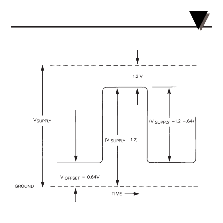
B. Frequency Output
1. Square wave pulse, unscaled (See Figure 4-1)
2. Output impedance 75 ohms
3. Directly proportional to flow rate
4. Output - dc frequency
5. Offset 0.64 volts
6. Peak voltage = Supply voltage - 1.2 volts
7. Peak to peak voltage Supply voltage - 1.2 volts - 0.64 volts
8. Output signal cycle 66.7% (i.e. at 100 Hz there is a 6 millisecond “on”
time and a 4 millisecond “off” time)
9. TTL/CMOS circuit compatibility. The FTB600B Series has an
operational amplifier output, which has a high input impedance and a
low output impedance.
Page 12

8
FTB600B Series
Infrared Sensors
4
C. Frequency Ranges for
(non-cartridge models) pulses/l
Model Frequency (Hz) K-Factor
FTB601B 60 to 1200 36,000
FTB602B 40 to 1200 8,000
FTB603B 27 to 800 3,200
FTB604B 20 to 600 1,200
FTB605B 18.75 to 562 450
FTB606B 15 to 450 225
D. Cable Requirements
1. 20 to 22 AWG (American Wire Gauge)
2. 4 conductor-shielded cable.
Avoid influences of strong electromagnetic forces as they
can damage components on the PC boards.
NOTE
Page 13
9
FTB600B Series
Infrared Sensors
4
Figure 4-1. Output Frequency Waveforms
Page 14

10
5
FTB600B Series
Installation
Section 5 - Installing the FTB600B Series in the fluid line.
A. Make sure the fluid is compatible with PVDF (polyvinylidene fluoride)
and meets viscosity, pressure and temperature parameters of the
FTB600B Series. The fluid must also meet filtration requirements as
listed in 3D.
B. Install the FTB600B series in the fluid line with the arrow pointing in
the direction of the flow.
C. While installing the FTB600B Series in the fluid line be careful not to
over-torque the end caps (on hose-barbed flowmeters) or other
fittings on the flowmeter. Due to the relatively soft composition of
PVDF the body or threads can be permanently distorted.
D. Attach wires to the readout display with the display and power off.
Not only will this help to avoid a potential shock hazard, but it can
also help prevent an error in hooking the flow meter to an incorrect
115 Vac supply.
E. Connect digital display to power supply and enter scaling factors for
both the rate and total. Follow the manufacturers instructions for
programming the digital display.
F. The FTB600B Series is now ready for use.
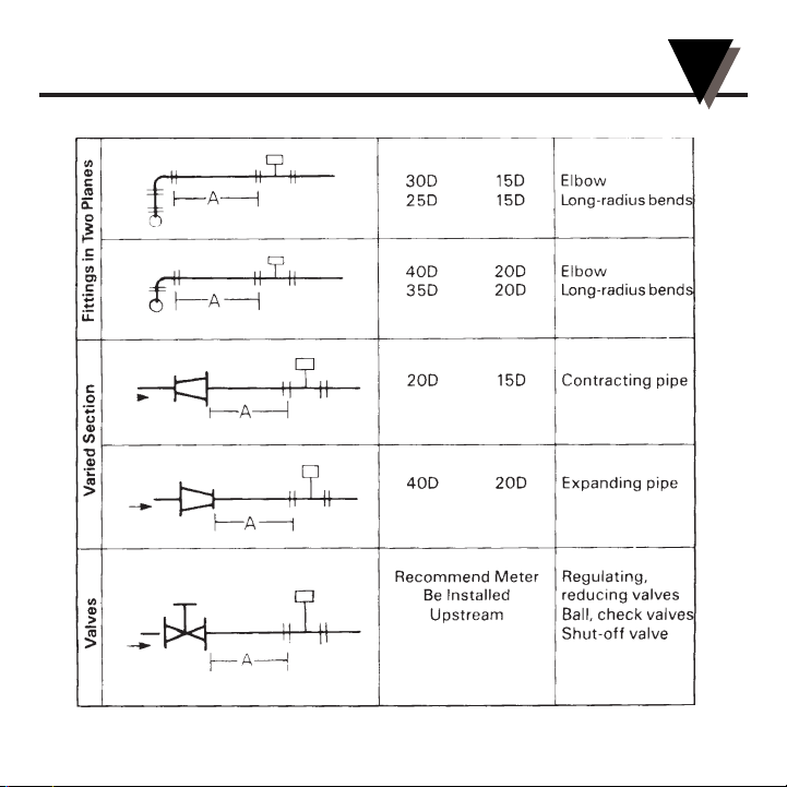
G. See Table 5-1 for straight pipe recommendations.
Page 15
11
FTB600B Series
Installation
5
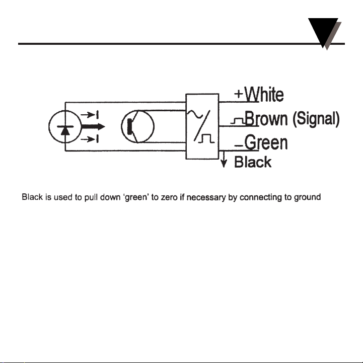
Figure 5-1. Supply Voltage and Signal Output Connections
Page 16

12
FTB600B Series
Installation
5
Table 5-1. Piping Table
Page 17
13
FTB600B Series
Installation
5
Table 5-1. Piping Table Con't.
Page 18

14
6
FTB600B Series
Specifications
Section 6 - Specifications
Accuracy: ±3% of reading
Repeatability: ±0.1% of reading
Linearity: ±1% of reading
Viscosity Range: 1 to 15 centistokes
Working Pressure: 150 PSIG at 175°F
Wetted Materials: PVDF
Power Supply: 5 to 18 Vdc, 6 to 33 mA
Output Signal: Unscaled square wave
Pressure Drop: See Section 7
Page 19

15
7
FTB600B Series
Pressure Drop Curves
Section 7 - Pressure Drop Curves
Pressure Drop FTB600B Series Liquid Turbine - Flowmeter FTB601
50
0.50 1.0
Liters/minute
kPa
1.5 2.0
45
40
35
30
25
20
15
10
5
0
Page 20

16
FTB600B Series
Pressure Drop Curves
7
Pressure Drop FTB600B Series Liquid Turbine - Flowmeter FTB602
250
2.00 4.0
Liters/minute
kPa
8.06.0 10.0
200
150
100
50
0
Page 21

17
FTB600B Series
Pressure Drop Curves
7
Pressure Drop FTB600B Series Liquid Turbine - Flowmeter FTB603
200
510150
Liters/minute
kPa
160
180
140
100
80
60
40
20
120
0
Page 22

18
FTB600B Series
Pressure Drop Curves
7
Pressure Drop FTB600B Series Liquid Turbine - Flowmeter FTB604
200
10 20 300
Liters/minute
kPa
160
180
140
100
80
60
40
20
120
0
Page 23

19
FTB600B Series
Pressure Drop Curves
7
Pressure Drop FTB600B Series Liquid Turbine - Flowmeter FTB605A
160
140
120
100
80
60
40
20
10 20 30 40 50 600
Liters/minute
kPa
0
Page 24

20
FTB600B Series
Pressure Drop Curves
7
Pressure Drop FTB600B Series Liquid Turbine - Flowmeter FTB606A
180
160
140
120
100
80
60
40
20
10 20 30 40 50 60 70 80900
Liters/minute
kPa
0
Page 25

FOR WARRANTY RETURNS, please have the
following information available BEFORE contacting
OMEGA:
1. Purchase Order number under which the
product was PURCHASED,
2. Model and serial number of the product under
warranty, and
3. Repair instructions and/or specific problems
relative to the product.
FOR NON-WARRANTY REPAIRS,
consult OMEGA
for current repair charges. Have the following
information available BEFORE contacting OMEGA:
1. Purchase Order number to cover the COST
of the repair,
2. Model and serial number of the product, and
3. Repair instructions and/or specific problems
relative to the product.
OMEGA’s policy is to make running changes, not model changes, whenever an improvement is possible. This affords our customers the
latest in technology and engineering.
OMEGA is a registered trademark of OMEGA ENGINEERING, INC.
© Copyright 2005 OMEGA ENGINEERING, INC. All rights reserved. This document may not be copied, photocopied, reproduced, translated, or
reduced to any electronic medium or machine-readable form, in whole or in part, without the prior written consent of OMEGA ENGINEERING, INC.
WARRANTY / DISCLAIMER
OMEGA ENGINEERING, INC. warrants this unit to be free of defects in materials and workmanship for a period
of 13 months from date of purchase. OMEGA’s WARRANTY adds an additional one (1) month grace period to
the normal one (1) year product warranty to cover handling and shipping time. This ensures that OMEGA’s customers receive maximum coverage on each product.
If the unit malfunctions, it must be returned to the factory for evaluation. OMEGA’s Customer Service Department will issue
an Authorized Return (AR) number immediately upon phone or written request. Upon examination by OMEGA, if the unit is
found to be defective, it will be repaired or replaced at no charge. OMEGA’s WARRANTY does not apply to defects resulting
from any action of the purchaser, including but not limited to mishandling, improper interfacing, operation outside of
design limits, improper repair, or unauthorized modification. This WARRANTY is VOID if the unit shows evidence of having
been tampered with or shows evidence of having been damaged as a result of excessive corrosion; or current, heat,
moisture or vibration; improper specification; misapplication; misuse or other operating conditions outside of OMEGA’s
control. Components in which wear is not warranted, include but are not limited to contact points, fuses, and triacs.
OMEGA is pleased to offer suggestions on the use of its various products. However, OMEGA neither
assumes responsibility for any omissions or errors nor assumes liability for any damages that result
from the use of its products in accordance with information provided by OMEGA, either verbal or
written. OMEGA warrants only that the parts manufactured by the company will be as specified and
free of defects. OMEGA MAKES NO OTHER WARRANTIES OR REPRESENTATIONS OF ANY KIND
WHATSOEVER, EXPRESSED OR IMPLIED, EXCEPT THAT OF TITLE, AND ALL IMPLIED WARRANTIES
INCLUDING ANY WARRANTY OF MERCHANTABILITY AND FITNESS FOR A PARTICULAR PURPOSE
ARE HEREBY DISCLAIMED. LIMITATION OF LIABILITY: The remedies of purchaser set forth herein
are exclusive, and the total liability of OMEGA with respect to this order, whether based on
contract, warranty, negligence, indemnification, strict liability or otherwise, shall not exceed the
purchase price of the component upon which liability is based. In no event shall OMEGA be liable for
consequential, incidental or special damages.
CONDITIONS: Equipment sold by OMEGA is not intended to be used, nor shall it be used: (1) as a “Basic
Component” under 10 CFR 21 (NRC), used in or with any nuclear installation or activity; or (2) in medical
applications or used on humans. Should any Product(s) be used in or with any nuclear installation or activity,
medical application, used on humans, or misused in any way, OMEGA assumes no responsibility as set forth in our
basic WARRANTY/ DISCLAIMER language, and, additionally, purchaser will indemnify OMEGA and hold OMEGA
harmless from any liability or damage whatsoever arising out of the use of the Product(s) in such a manner.
RETURN REQUESTS / INQUIRIES
Direct all warranty and repair requests/inquiries to the OMEGA Customer Service Department. BEFORE RETURNING
ANY PRODUCT(S) TO OMEGA, PURCHASER MUST OBTAIN AN AUTHORIZED RETURN (AR) NUMBER FROM
OMEGA’S CUSTOMER SERVICE DEPARTMENT (IN ORDER TO AVOID PROCESSING DELAYS). The assigned AR
number should then be marked on the outside of the return package and on any correspondence.
The purchaser is responsible for shipping charges, freight, insurance and proper packaging to prevent breakage in transit.
Page 26

TEMPERATURE
䡺⻬
Thermocouple, RTD & Thermistor
Probes, Connectors, Panels & Assemblies
䡺⻬
Wire: Thermocouple, RTD & Thermistor
䡺⻬
Calibrators & Ice Point References
䡺⻬
Recorders, Controllers & Process Monitors
䡺⻬
Infrared Pyrometers
PRESSURE, STRAIN
AND FORCE
䡺⻬
Transducers & Strain Gages
䡺⻬
Load Cells & Pressure Gages
䡺⻬
Displacement Transducers
䡺⻬
Instrumentation & Accessories
FLOW/LEVEL
䡺⻬
Rotameters, Gas Mass Flowmeters
& Flow Computers
䡺⻬
Air Velocity Indicators
䡺⻬
Turbine/Paddlewheel Systems
䡺⻬
Totalizers & Batch Controllers
pH/CONDUCTIVITY
䡺⻬
pH Electrodes, Testers & Accessories
䡺⻬
Benchtop/Laboratory Meters
䡺⻬
Controllers, Calibrators, Simulators
& Pumps
䡺⻬
Industrial pH & Conductivity Equipment
DATA ACQUISITION
䡺⻬
Data Acquisition &
Engineering Software
䡺⻬
Communications-Based
Acquisition Systems
䡺⻬
Plug-in Cards for Apple, IBM
& Compatibles
䡺⻬
Datalogging Systems
䡺⻬
Recorders, Printers & Plotters
HEATERS
䡺⻬
Heating Cable
䡺⻬
Cartridge & Strip Heaters
䡺⻬
Immersion & Band Heaters
䡺⻬
Flexible Heaters
䡺⻬
Laboratory Heaters
ENVIRONMENTAL
MONITORING AND CONTROL
䡺⻬
Metering & Control Instrumentation
䡺⻬
Refractometers
䡺⻬
Pumps & Tubing
䡺⻬
Air, Soil & Water Monitors
䡺⻬
Industrial Water & Wastewater
Treatment
䡺⻬
pH, Conductivity & Dissolved
Oxygen Instruments
Where Do I Find Everything I Need for
Process Measurement and Control?
OMEGA…Of Course!
Shop online at omega.com
M1132/0405
 Loading...