

Page 1
EZPanel Enhanced
Re-Order from
omegamation.com
Omegamation
TM
1-888-55-OMEGA
1-888-55-66342
1-888-55-66342
Programming Software Manual
Manual Part Number EZP-PANELEDIT-M
Revision A.1
Page 2

This page intentionally left blank.
Page 3

The Most Sensible Automation Products
Re-Order from
omegamation.com
Omegamation
TM
1-888-55-OMEGA
1-888-55-66342
1-888-55-66342
Direct From the Factory
EZPanel Enhanced
Programming Software Manual
Manual Part Number EZP-PANELEDIT-M
Revision A.1
Page 4

WARNING!
Programmable control devices such as EZPanel Enhanced are not fail-safe devices and as such
must not be used for stand-alone protection in any application. Unless proper safeguards are used,
unwanted start-ups could result in equipment damage or personal injury. The operator must be made
aware of this hazard and appropriate precautions must be taken.
In addition, consideration must be given to the use of an emergency stop function that is independent
of the programmable controller.
The diagrams and examples in this user manual are included for illustrative purposes only. The
manufacturer cannot assume responsibility or liability for actual use based on the diagrams and
examples.
CAUTION
Do not press the EZPanel Enhanced touchscreen with any sharp objects. This practice may damage
the unit beyond repair.
Trademarks
This publication may contain references to products produced and/or offered by other companies.
The product and company names may be trademarked and are the sole property of their respective
owners. EZ Automation disclaims any proprietary interest in the marks and names of others.
Manual Part Number:
EZP-PANELEDIT-M
© Copyright 2005, EZ Automation
All Rights Reserved
No part of this manual shall be copied, reproduced, or transmitted in any way without the prior
written consent of EZAutomation. EZAutomation retains the exclusive rights to all information
included in this document.
MANUFACTURED by AVG
4140 Utica Ridge Rd. • Bettendorf, IA 52722-1327
MARKETED by EZ Automation
4140 Utica Ridge Rd. • Bettendorf, IA 52722-1327
Phone: 1-877-774-EASY • Fax: 1-877-775-EASY • www.EZAutomation.net
EZP-PANELEDIT-M
Page 5

Editor Programming Software User Manual
Table of Contents
WARNING/Caution ......................................................................................................... inside front cover
Table of Contents .......................................................................................................................................i
EU Information .........................................................................................................................................ix
Compatability of Software
Software Enhancements ....................................................................................................................... xi
Enhancements for AB Drivers ................................................................................................................xi
New PLC/Drivers Added .........................................................................................................................xi
Chapter 1
Manual Organization ...................................................................................................................................2
Introduction .................................................................................................................................................3
What you need to get started ......................................................................................................................3
Hardware ...............................................................................................................................................3
Software ................................................................................................................................................3
Need Help? .................................................................................................................................................4
Onscreen HELP ....................................................................................................................................4
Fly-Over HELP ......................................................................................................................................4
PLC HELP .............................................................................................................................................4
Technical Support ..................................................................................................................................4
EZPanel Enhanced Models .........................................................................................................................5
6-inch Monochrome Models ..................................................................................................................5
6-inch Color Models ..............................................................................................................................6
8-inch Color Models ..............................................................................................................................7
10-inch and 15-inch Models ..................................................................................................................8
Features .................................................................................................................................................9
PLCs Supported by EZPanel Enhanced ...................................................................................................10
PLC Cable Part Numbers ..........................................................................................................................11
EZPanel Enhanced Editor Programming Software ..................................................................................12
Installing the Software .........................................................................................................................12
EZLaunch Pad ...........................................................................................................................................15
......................................................................................................... x
Chapter 2
Tutorial—Confi gure PLC ........................................................................................................................18
Tutorial—Create a Project ......................................................................................................................19
Step 1 ...............................................................................................................................................19
Step 2 ...............................................................................................................................................21
Step 3 ...............................................................................................................................................28
Chapter 3
Project Setup ...........................................................................................................................................32
Decide now if you want to work ON-LINE or OFF-LINE ......................................................................32
Step 1 Project Information .................................................................................................................33
SELECT ACTION ............................................................................................. ...........................33
Edit Program OFF-LINE (Write to Panel Later) ......................................................................33
Read Program from Panel and Edit OFF-LINE ......................................................................35
Edit Program ON-LINE ...........................................................................................................36
A QUICK REVIEW for “ENTER PROJECT INFORMATION” .......................................................37
Step 2 Design Your Screens .............................................................................................................39
Step 3 Write Your Program to Panel ..................................................................................................41
v
Page 6

Editor Programming Software User Manual
Chapter 4
Objects Menu ..........................................................................................................................................44
Button Object .......................................................................................................................................46
Protection Tab ..............................................................................................................................48
Visibility/Details Tab ......................................................................................................................50
Indicator Button Object ........................................................................................................................51
Radio Buttons ......................................................................................................................................53
Switch Object ......................................................................................................................................56
Step Switch Object ..............................................................................................................................58
Tri-State Switch Object ........................................................................................................................60
Numeric Entry Object ..........................................................................................................................62
Scaling Tab ..................................................................................................................................64
Recipe Object ......................................................................................................................................66
Thumbwheel Object ............................................................................................................................69
Indicator Light Object ..........................................................................................................................71
Numeric Display Object .......................................................................................................................73
Scaling Tab ...................................................................................................................................75
Text Objects .........................................................................................................................................76
Static Text .....................................................................................................................................76
Triggered Text ...............................................................................................................................77
Lookup Text ..................................................................................................................................79
Message Database ................................................................................................................80
Dynamic Text ................................................................................................................................81
Text Entry .....................................................................................................................................83
Clock Objects ......................................................................................................................................85
Analog Clock ................................................................................................................................85
Digital Clock .................................................................................................................................86
Meter Object ........................................................................................................................................87
Alarms Tab ...................................................................................................................................88
Digital Display Tab ........................................................................................................................89
Scaling Tab ...................................................................................................................................90
Bar Graph Object ................................................................................................................................92
Digital Display Tab ........................................................................................................................93
Scaling Tab ...................................................................................................................................94
Line Graph Object ...............................................................................................................................95
Pen Tab ........................................................................................................................................97
XY Axis Tab ..................................................................................................................................97
PID Faceplate Object ..........................................................................................................................99
Legends Tab ...............................................................................................................................101
Change Screen Object ......................................................................................................................102
Alarm History Object .........................................................................................................................104
System Objects .................................................................................................................................106
Increment/Decrement Hour ........................................................................................................106
Activate Screen Saver ................................................................................................................108
Adjust Contrast ...........................................................................................................................109
Select Language ........................................................................................................................111
Multi-state Indicator Object ................................................................................................................ 112
Messages Tab ............................................................................................................................114
Embedding a Data Value ......................................................................................................115
Copy Messages ...................................................................................................................118
Bitmap Objects ..................................................................................................................................120
Dynamic Bitmap ........................................................................................................................120
Bitmap Button ............................................................................................................................123
vi
Page 7

Editor Programming Software User Manual
Multi-state Bitmap .......................................................................................................................126
Images Tab ...........................................................................................................................128
Increment/Decrement Value Object ..................................................................................................131
View File Object ................................................................................................................................133
Chapter 5
Main Programming Screen ..................................................................................................................136
Title Bar .............................................................................................................................................136
Main Menu Bar ..................................................................................................................................136
Standard Tool Bar ..............................................................................................................................137
Object Tool Bars ................................................................................................................................138
Basic Objects Tool Bar ...............................................................................................................138
Text Objects Tool Bar .................................................................................................................139
System Objects Tool Bar ............................................................................................................139
Bitmap Objects Tool Bar .............................................................................................................139
Draw Tool Bar ....................................................................................................................................140
Panel Tool Bar ...................................................................................................................................140
Status Bar ..........................................................................................................................................140
3 Easy Steps Tool Bar .......................................................................................................................141
Project Screen Explorer View ............................................................................................................141
Programming Screen ........................................................................................................................142
Chapter 6
Reference .............................................................................................................................................144
File Menu ...........................................................................................................................................144
Edit Menu ..........................................................................................................................................149
Overlapping Objects ...................................................................................................................151
Pick and Apply Attributes ............................................................................................................152
Simulate Next and Previous States ............................................................................................153
Screen Menu .....................................................................................................................................154
Objects Menu ....................................................................................................................................158
Draw Menu ........................................................................................................................................159
Sizing a Bitmap in Symbol Factory .............................................................................................162
Panel Menu .......................................................................................................................................163
Setup Menu .......................................................................................................................................167
Tag Database .............................................................................................................................167
Tag Cross Reference ..................................................................................................................170
Export Tags ................................................................................................................................171
Import Tags .................................................................................................................................172
Alarm Database ..........................................................................................................................175
Export Alarms .............................................................................................................................177
Message Database ....................................................................................................................178
Export Messages ........................................................................................................................180
Project Attributes ........................................................................................................................181
General tab ..........................................................................................................................181
Printer tab .............................................................................................................................182
Passwords tab ......................................................................................................................183
Clock tab ..............................................................................................................................184
Panel to PLC tab ..................................................................................................................185
PLC to Panel tab ..................................................................................................................187
How do I switch screens from a PLC? ..............................................................................187
Language tab .......................................................................................................................189
Alarm Protection tab .............................................................................................................190
Project Description .....................................................................................................................191
vii
Page 8

Editor Programming Software User Manual
Select PLC .................................................................................................................................191
Upgrade Firmware ......................................................................................................................192
Window Menu ....................................................................................................................................194
Help Menu .........................................................................................................................................195
Right Click Menus .............................................................................................................................196
Symbol Factory® ...............................................................................................................................197
Appendix A Troubleshooting
Frequently Asked Questions (FAQs) ................................................................................................. A-2
Troubleshooting ................................................................................................................................. A-5
PLC Driver Error Messages ............................................................................................................A-15
EZPanel Enhanced Error Messages ...............................................................................................A-61
EZPanel Enhanced Programming Software Error Messages ......................................................... A-62
Appendix B ASCII and ANSI Characters
EZPanel Enhanced ASCII Characters ..............................................................................................B-2
EZPanel Enhanced ANSI Characters ................................................................................................B-5
Appendix C PLC Communications Setup
Allen-Bradley PLC Communications Setup .......................................................................................C-3
MicroLogix DF1 Full Duplex .......................................................................................................C-3
MicroLogix DF1 Half Duplex .......................................................................................................C-4
MicroLogix DH485/AIC ...............................................................................................................C-5
SLC 5/03, 5/04 and 5/05 DF1 Full Duplex ..................................................................................C-6
SLC 5/03, 5/04 and 5/05 DF1 Half Duplex .................................................................................C-7
SLC 500, 5/01, 5/02 and 5/03 D485/AIC ....................................................................................C-8
PLC 5 DF1 ..................................................................................................................................C-9
Data Highway Plus ...................................................................................................................C-10
Remote I/O ...............................................................................................................................C-12
Generic DeviceNet I/O Communications Setup ..............................................................................C-14
DirectLogic PLC Communications Setup ........................................................................................C-16
Generic EtherNet/IP Communications Setup ..................................................................................C-17
General Electric (GE) PLC Communications Setup .......................................................................C-20
GE 90-30/90-70 SNPX .............................................................................................................C-20
GE VERSAMAX .......................................................................................................................C-21
Mitsubishi PLC Communications Setup Mitsubishi CC Link ...........................................................C-22
Modicon PLC Communications Setup .............................................................................................C-23
Omron C200 and C500 PLC Communications Setup .....................................................................C-24
Generic Profi bus-DP PLC Communications Setup .........................................................................C-26
Siemens S7 MPI Adaptor PLC Communications Setup ..................................................................C-30
Entivity’s Think &Do (WinPLC) Communications Setup ..................................................................C-32
Aromat ...........................................................................................................................................C-35
Control Techniques ..........................................................................................................................C-36
Control Technology Corporation (CTC) ...........................................................................................C-37
Idec ...........................................................................................................................................C-38
Mitsubishi CC Link ...........................................................................................................................C-39
Siemens S7_200 Protocol ...............................................................................................................C-40
Square D Symax .............................................................................................................................C-41
Texas Instruments ...........................................................................................................................C-41
Uni-Telway .......................................................................................................................................C-43
Universal Ethernet: Ethernet I/P, DF1 over Ethernet, Modbus TCP/IP, GE SRTP ..........................C-44
Appendix D Setting COM1 for a Printer
Setting COM1 for Printer ...................................................................................................................D-2
viii
Page 9

Editor Programming Software User Manual
EU Information
The EZPanel Enhanced is manufactured in compliance with European Union (EU) Directives and
carries the CE mark. EZPanel Enhanced has been tested under CE Test Standard #EN55011, and is
listed under UL File #E209355. The following information is provided to comply with EU documentation
requirements.
Please NOTE: Products with CE marks perform their required functions safely
and adhere to relevant standards as specifi ed by EU Directives provided they are
used according to their intended purpose and that the instructions in this manual
are adhered to. The protection provided by the equipment may be impaired if
this equipment is not used in accordance with this manual. Only replacement
parts supplied by EZAutomation or its agents should be used.
Technical Support
SELV Circuits
Environmental
Specifi cations
Consult EZPanel Enhanced Editor Programming Software Help or you may fi nd
answers to your questions in the operator interface section of our website @
www.EZAutomation.net. If you still need assistance, please call our technical
support from 6 a.m. to Midnight CST at 1-877-774-EASY or FAX us at 1-877775-EASY.
All electrical circuits connected to the communications port receptacle are rated
as Safety Extra Low Voltage (SELV).
Operating Temperature
6” White on Blue & Mono non-expandable ...............................0 to 45 °C
6” Color .....................................................................................0 to 50 °C
6” Color TFT ..............................................................................0 to 55 °C
8” Color .....................................................................................0 to 50 °C
8” Color TFT ..............................................................................0 to 55 °C
10” Color ...................................................................................0 to 55 °C
15” Color ...................................................................................0 to 55 °C
Storage Temperature
6” White on Blue & Mono non-expandable ......................... -20 to +60 °C
6” Color .............................................................................. -25 to +60 °C
6” Color TFT ........................................................................ -25 to +65 °C
8” Color ............................................................................... -25 to +60 °C
8” Color TFT ........................................................................ -25 to +65 °C
10” Color ............................................................................. -25 to +65 °C
15” Color ............................................................................. -25 to +65 °C
Operating Humidity ..................................10 - 95% R.H>, noncondensing
Air Composition ............................................ No corrosive gases permitted
Preventative Maintenance and Cleaning
No preventative maintenance is required. The EZPanel Enhanced touchscreen
should be cleaned as needed with warm, soapy water. See the EZPanel Enhanced
Hardware Manual (P/N EZP-PANEL-M) for a list of compatible/incompatible
chemicals and compounds.
ix
Page 10
Editor Programming Software User Manual
EZPanel Enhanced Editor
The EZPanel Enhanced product has been modifi ed to offer new features in:
• Software
• Drivers
Compatibility of Software
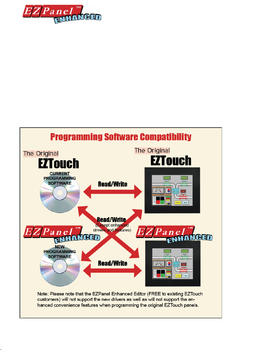
The EZPanel Enhanced Editor Software is compatible with current EZTouch Panels (from ADC) as well
as the new EZPanel Enhanced models. However, EZPanel Enhanced Editor Programming Software
does not allow current EZTouch Panels (from ADC) to utilize software upgrades, Enhanced drivers
(Universal Ethernet, Aromat Mewtocol COM, Control Techniques, Control Technology Corp. (CTC),
EZPLC, Idec Computer Link, Mitsubishi CC Link, Siemens S7_200, Square D Symax, and Texas
Instruments), or Enhanced Features (Overlapping of Objects, Free Sizing of Touch Objects, Display
of Tag Address on Objects, and Pick and Apply Style).
EZPanel Enhanced Editor Programming Software Enhancements
x
Page 11

Editor Programming Software User Manual
EZPanel Enhanced Editor Programming Software Enhancements
• Overlapping of objects
• Free-sizing of touch objects
• Added convenience features such as pick and apply attributes and display address on
objects
• Report object
• View File object added for EZCE Touchpanel
Enhancement for AB Drivers
• Support for ST & Long File types in AB Drivers
• Support for full range of I/O and direct addressing of I/O for DF1 and Micrologix
• Support ControlLogix and Compact Logix Tag names
• Support for binary fi les (B3:0/0) using the shortcut method of B3/0, B3/1, and B3/2
New PLC/Drivers added
• Aromat
• Control Techniques - Unidrive 2-wire, 4-wire (binary)
• Control Technology Corporation (CTC) - CTC2600, 2700, and 5100 (CTC Binary)
• Idec - Computer Link
• Mitsubishi - CC Link (CC Link protocol)
• Siemens S7_200
• Square D Symax - 300 Series CPU, 400 Series CPU (Symax)
• Texas Instruments - TI5x5 Series, TI505, TI545-1102, TI545-1104
• Uni Telway - Telemecanique TSX 37 Micro (UNI-TE Version 1.1)
• Universal Ethernet: Ethernet/IP, DF1 over Ethernet, Modbus TCP/IP, GE SRTP
xi
Page 12

Editor Programming Software User Manual
This page intentionally left blank.
xii
Page 13

1
Introduction
In this chapter....
— Manual Organization
— Introduction
— What you need to get started
— Need HELP?
— Models
— Features
— PLCs Supported by EZPanels
— PLC Cable Part Numbers
— Programming Cable Part Number
— EZPanel Enhanced Editor Programming Software
Installation
Page 14
Editor Programming Software User Manual
Manual Organization
The EZPanel Enhanced Editor Programming Software User Manual is arranged in chapters. A description of key
information contained in each chapter is provided below.
Chapter Description
Introduction
Provides Manual Organization, and lists what you need to get started, hardware and
Introduction
1
2
3
4
5
software. Discusses how to get help with questions or problems you might encounter
through Onscreen Help and Technical Support. Provides you with a table listing the
various models, their part numbers and special features. Lists the important features
of all EZPanel Enhanced models. Lists the PLCs supported by the panels, by brand,
model and protocol. Lists the part numbers for PLC cables and the programming
cable. Tells how to install programming software.
Tutorial
Provides instructions to create an example (or “demo”) project. Discusses how
to confi gure a PLC ladder logic program to use with the demo project. Takes you
through the steps necessary to create an EZPanel Enhanced project using the programming software. Shows you how to transfer the project to the panel, and testing
the project once transferred.
Project Setup
Discusses ON-LINE and OFF-LINE confi guration options. Tells you how to set up a
project by entering project information (Step 1). Discusses screen design (Step 2), and
how to transfer the project to the panel (Step 3).
Objects
Provides step-by-step instructions for confi guring each of the EZPanel Enhanced
objects.
Reference
Provides more details on menu commands. Takes you through the main menu bar
item by item, command by command, with instructions. Contains information on the
various tool bars and the status bar. Describes right click menus and Screens Explorer
view.
Appendix A Troubleshooting
Aids in diagnosing problems you might encounter when installing or operating your
A
B
C
D
EZPanel Enhanced. Provides steps to take to isolate and correct problems. Lists
panel error messages, programming software error messages, and PLC Driver Error
messages.
Appendix B Characters
Provides a list of the ASCII Characters supported by the EZPanel Enhanced. This
information may be useful when creating a Text Entry or Dynamic Text object.
Appendix C PLC Communications Setup
Provides instructions on how to set up most PLC Types to communicate with the
EZPanel Enhanced.
Appendix D Setting COM1 to Printer
Provides instructions on how to set COM1 on the EZPanel Enhanced to “Printer.”
2
Page 15
Editor Programming Software User Manual
Introduction
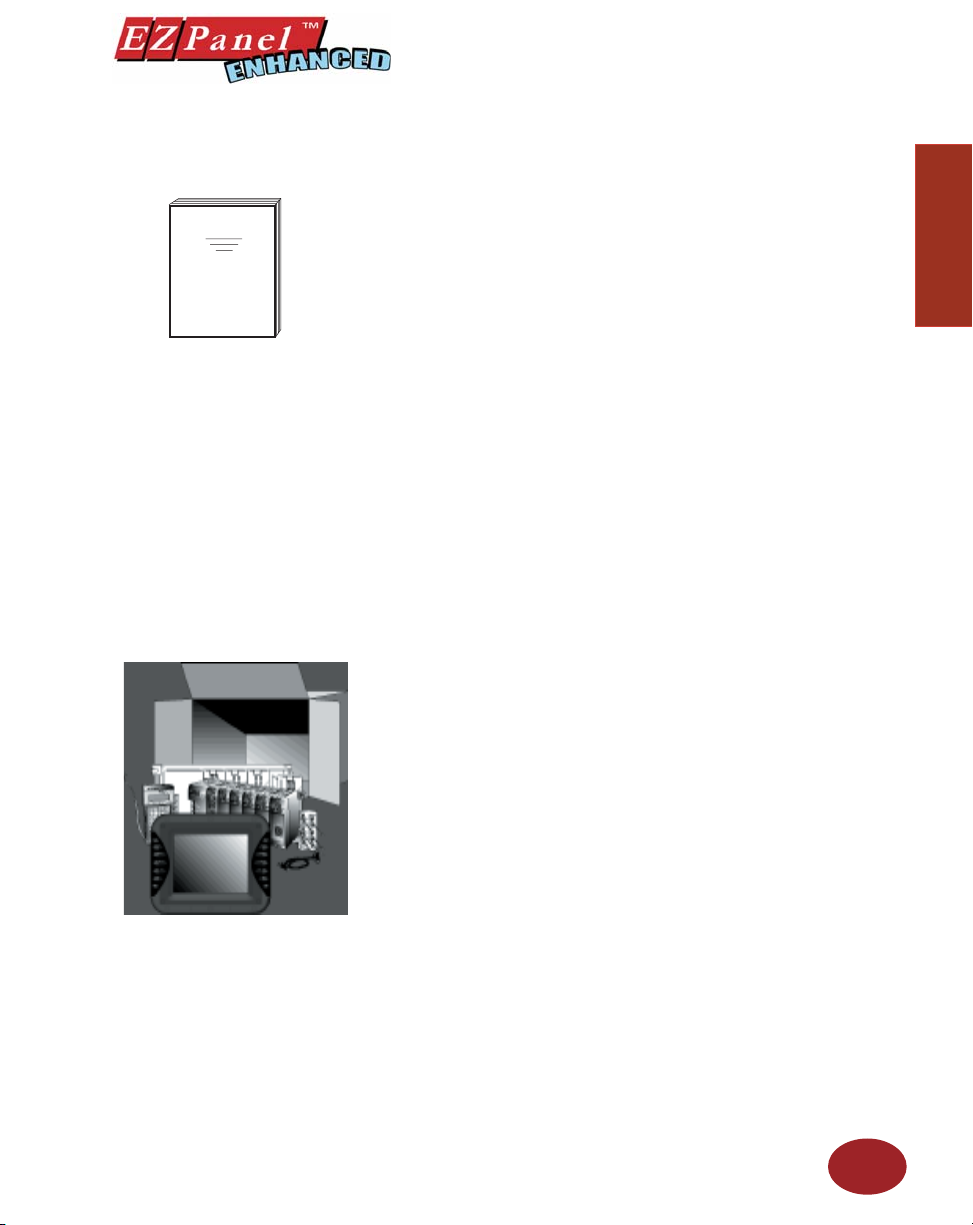
EZPanel Enhanced
Install the EZPanel Enhanced
using the instructions in the
Hardware Manual.
Program the EZPanel Enhanced
using the instructions in this
Software Manual.
There are two manuals that you will need for installation — this manual, the
EZPanel Enhanced Editor Programming Software User Manual, and the
EZPanel Enhanced Hardware User Manual ( P/N EZP-PANEL-M) shipped
with your EZPanel Enhanced.
These manuals will take you through the steps necessary to get your
EZPanel Enhanced up and running in the shortest possible time. Although
your familiarity with programmable graphic operator interface devices will
determine how quickly you move through the steps — it’s as easy as 1
— 2 — 3.
What you need to get started....
Hardware
• EZPanel Enhanced
• 24 Volt DC Power Supply (1.5 AMP or larger Slo-Blo input
• RS-232C Programming Cable ( P/N EZP-PGMCBL)
• RS-232C or RS-422A/485A PLC Interface Cable (see page 11
• PC requirements:
— IBM or compatible PC (Pentium 166 MHZ or better)
with a mouse and separate serial port
— VGA display with at least 800 x 600 resolution
— Standard Windows 98/NT4.0/2000/XP Professional/
— CD ROM Drive
power fuse recommended)
for part numbers)
(1024 x 768 recommended)
XP Home® Requirements
Introduction
Introduction
Software
• EZPanel Enhanced Editor Programming Software
( P/N EZP-PANELEDIT)
3
Page 16
Need HELP?
Editor Programming Software User Manual
Introduction
be able to help you with most problems you might encounter.
PLEASE NOTE: The Troubleshooting section (Appendix A) should
Onscreen HELP
One of the most important features of the EZPanel Enhanced Editor
Programming Software is the availability of context sensitive onscreen help.
To access the Help windows, simply press the F1 function key while on the
topic where you need help. For example, if you need help while working
with screens, press the F1 function key while in that area and a popup
window will be displayed. You may also click on the Help button located
at the bottom of most dialog boxes to go to the help topic.
Fly-Over HELP
When the mouse cursor comes to rest over any tool bar or object button
for a short while, a small window will appear containing a brief description
of the function of that particular button. The window will disappear as soon
as the cursor has been moved off the button.
PLC HELP
If you need help with the PLC to EZPanel Enhanced Interface, consult the
EZPanel Enhanced Editor Programming Software Help. Each PLC Driver
has a Help Topic that lists the error messages and provides an explanation
for each. Also provided are PLC to EZPanel Enhanced wiring diagrams.
Technical Support
Although most questions can be answered with EZPanel Enhanced HELP
or the manuals, you may fi nd answers to your questions in the operator
interface section of our web site @ www.EZAutomation.net. If you still
need assistance, please call our technical support from 6 a.m. to Midnight
at 1-877-774-EASY or FAX us at 1-877-775-EASY.
Warranty Repairs
If your EZPanel Enhanced is under warranty, contact www.EZAutomation.
net or call us @ 1-877-774-EASY.
Out of Warranty Repairs
If your EZPanel Enhanced is out of warranty, contact EZAutomation’s
Service Department for an evaluation of repair costs @ 1-877-774EASY. You can then decide whether it is more economical to proceed with
factory repairs or purchase a new panel.
4
Page 17
EZPanel Models
Editor Programming Software User Manual
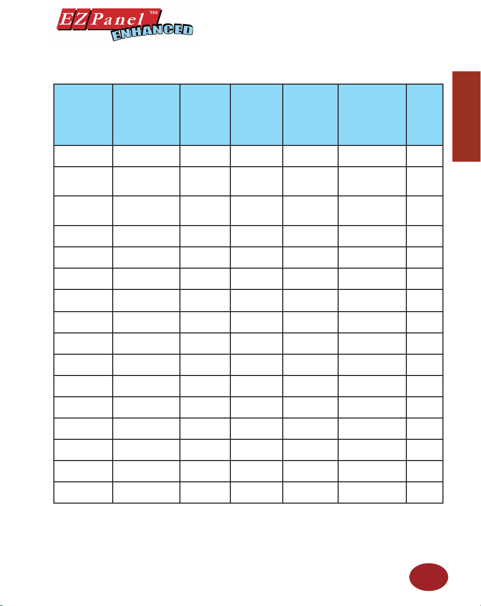
6-inch Monochrome EZPanel Enhanced Models
Part Number Description
EZP-S6M-R
*EZP-S6W-RS
*EZP-S6W-RSU
EZP-S6M-RS
EZP-S6M-F
EZP-S6M-FH
EZP-S6M-FS
EZP-S6M-FSH
*EZP-S6M-FSD
*EZP-S6M-FSE
*EZP-S6M-FSM
*EZP-S6M-FSP
*EZP-S6M-FST
*EZP-S6M-FSC
*EZP-S6M-FSU
*EZP-S6M-ES
6” Mono with
Standard Bezel
6” Mono White
on Blue with Slim
Bezel
6” Mono White
on Blue with Slim
Bezel
6” Mono with Slim
Bezel
6” Mono with
Standard Bezel
6” Mono with
Standard Bezel
6” Mono with Slim
Bezel
6” Mono with Slim
Bezel
6” Mono with Slim
Bezel
6” Mono with Slim
Bezel
6” Mono with Slim
Bezel
6” Mono with Slim
Bezel
6” Mono Grayscale
with Slim Bezel
6” Mono Grayscale
with Slim Bezel
6” Mono Grayscale
with Slim Bezel
6” Mono Grayscale
with Slim Bezel
User
Memory
256KB No No See Note below
256KB No No All Serial Drivers
256KB No No
256KB No No See Note below
512KB
512KB
512KB
512KB
512KB
512KB
512KB
512KB
512KB
512KB
512KB
512KB
Field
Expandable
User RAM?
Yes, to 1 or
2 MB
Yes, to 1 or
2 MB
Yes, to 1 or
2 MB
Yes, to 1 or
2 MB
Yes, to 1 or
2 MB
Yes, to 1 or
2 MB
Yes, to 1 or
2 MB
Yes, to 1 or
2 MB
Yes, to 1 or
2 MB
Yes, to 1 or
2 MB
Yes, to 1 or
2 MB
Yes, to 1 or
2 MB
Card Option
for Program
Nonvola-
tile Flash
Backup
PLC Drivers
Upported?
Backup?
ONLY Universal
Ethernet
Yes
Yes
Yes
Yes
Yes All, plus DeviceNet
Yes
Yes All, plus MB+
Yes All, plus Profi bus
Yes
Yes All, plus CC Link
Yes
Yes ONLY EZPLC
All, plus EZ
Ethernet
All, plus AB DH+
and Remove I/O
All, plus EZ
Ethernet
All, plus AB DH+
and Remove I/O
All, plus Ethernet
I/P
All, plus ModBus
TCP/IP
ONLY Universal
Ethernet
NEMA
NEMA 4,
4X
NEMA 1,
FDA
NEMA 1,
FDA
NEMA 1,
FDA
NEMA 4,
4X
NEMA 4,
4X
NEMA 1,
FDA
NEMA 1,
FDA
NEMA 1,
FDA
NEMA 1,
FDA
NEMA 1,
FDA
NEMA 1,
FDA
NEMA 1,
FDA
NEMA 1,
FDA
NEMA 1,
FDA
NEMA 1,
FDA
Introduction
Introduction
EZAutomation EZPanel NEMA Ratings
The NEMA rating of all operator interface products in this manual relates to only the front bezel since only the front bezel is exposed to the external
environment and the backend is enclosed inside an appropriately sealed enclosure used by the customer. The Touchpanels in this manual have either
NEMA 1 FDA Compliant or NEMA 4, 4X (indoor) rating. Please note that the touchpanels that are rated NEMA 1 FDA Compliant can handle typical
NEMA 4, 4X environments such as water splashing or hosedown. The only reason these panels do not have NEMA 4, 4X rating is because the plastic
material used for NEMA 1 FDA Compliant models does not support the fl ame retardancy required for NEMA 4 models.
5
Page 18
Editor Programming Software User Manual
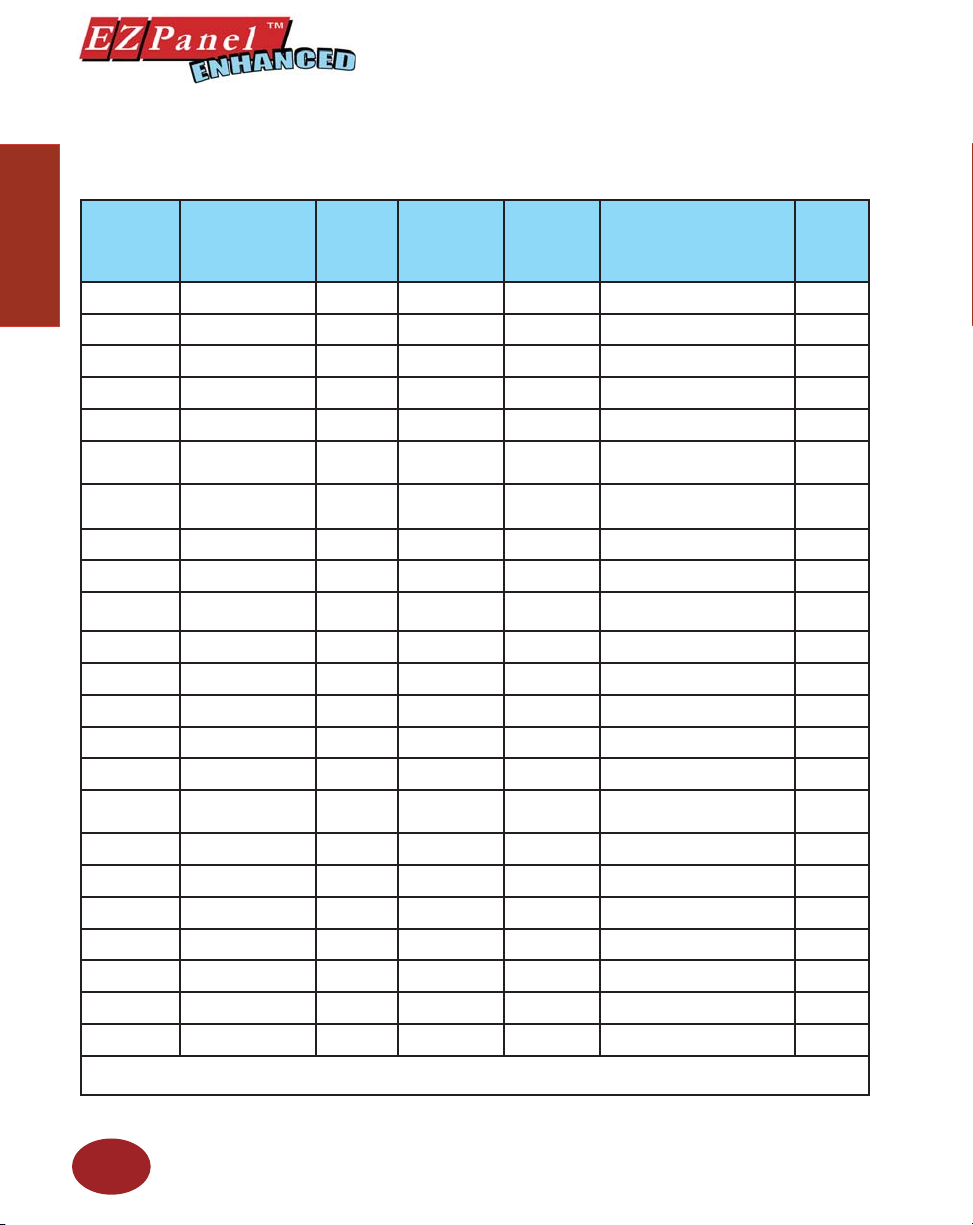
6-inch Color EZPanel Enhanced Models
In the table below are the 6-inch Color EZPanel Enhanced models. If using an option board connector, you
cannot use the PLC port at the same time to connect to another type PLC. The panel supports only one
PLC driver at a time.
Part Number Description
Introduction
EZP-S6C-K
EZP-S6C-KS
EZP-S6C-F
EZP-S6C-FH
EZP-S6C-FS
EZP-T6C-FS
*EZP-S6C-FSD
*EZP-T6C-FSD
*EZP-S6C-FSE
*EZP-T6C-FSE
EZP-S6C-FSH
EZP-T6C-FSH
EZP-S6C-FSM
EZP-T6C-FSM
EZP-S6C-FSP
EZP-T6C-FSP
*EZP-S6C-FST
*EZP-T6C-FST
*EZP-T6C-FSC
*EZP-S6C-FSU
*EZP-T6C-FSU
*EZP-S6C-ES
EZP-T6C-ES
*Indicates NEW EZPanel Enhanced Models.
NOTE: Suppots Automation Direct (Direct Logic) serial drivers including H2-WPLC-XX.
6” STN Color with
Standard Bezel
6” STN Color with
Slim Bezel
6” STN Color with
Standard Bezel
6” STN Color with
Standard Bezel
6” STN Color with
Slim Bezel
6” TFT Color with Slim
Bezel
6” STN Color with
Slim Bezel
6” TFT Color with Slim
Bezel
6” STN Color with
Slim Bezel
6” TFT Color with Slim
Bezel
6” STN Color with
Slim Bezel
6” TFT Color with Slim
Bezel
6” STN Color with
Slim Bezel
6” TFT Color with Slim
Bezel
6” STN Color with
Slim Bezel
6” TFT Color with Slim
Bezel
6” STN Color with
Slim Bezel
6” TFT Color with Slim
Bezel
6” STN Color with
Slim Bezel
6” STN Color with
Slim Bezel
6” TFT Color with Slim
Bezel
6” STN Color with
Slim Bezel
6” TFT Color with Slim
Bezel
User
Memory
512KB
512KB
512KB
512KB
512KB
512KB
512KB
512KB
512KB
512KB
512KB
512KB
512KB
512KB
512KB
512KB
512KB
512KB
512KB
512KB
512KB
512KB
512KB
Field
Expandable
User RAM?
Yes, to 1 or
2 MB
Yes, to 1 or
2 MB
Yes, to 1 or
2 MB
Yes, to 1 or
2 MB
Yes, to 1 or
2 MB
Yes, to 1 or
2 MB
Yes, to 1 or
2 MB
Yes, to 1 or
2 MB
Yes, to 1 or
2 MB
Yes, to 1 or
2 MB
Yes, to 1 or
2 MB
Yes, to 1 or
2 MB
Yes, to 1 or
2 MB
Yes, to 1 or
2 MB
Yes, to 1 or
2 MB
Yes, to 1 or
2 MB
Yes, to 1 or
2 MB
Yes, to 1 or
2 MB
Yes, to 1 or
2 MB
Yes, to 1 or
2 MB
Yes, to 1 or
2 MB
Yes, to 1 or
2 MB
Yes, to 1 or
2 MB
Nonvolatile
Flash Backup
Card Option
for Program
Backup?
Yes ONLY Direct Logic PLC
Yes ONLY Direct Logic PLC
Yes All, plus EZ Ethernet
Yes All, plus AB DH+ and Remote I/O
Yes All, plus EZ Ethernet
Yes All, plus EZ Ethernet
Yes All, plus DeviceNet
Yes All, plus DeviceNet
Yes All, plus Ethernet I/P
Yes All, plus Ethernet I/P
Yes All, plus AB DH+ and Remote I/O
Yes All, plus AB DH+ and Remote I/O
Yes All, plus MB+
Yes All, plus MB+
Yes All, plus Profi bus
Yes All, plus Profi bus
Yes All, plus ModBus TCP/IP
Yes All, plus ModBus TCP/IP
Yes All, plus CC Link
Yes ONLY Universal Ethernet
Yes ONLY Universal Ethernet
Yes ONLY EZPLC
Yes ONLY EZPLC
PLC Drivers Upported? NEMA
NEMA 4,
4X
NEMA 1,
FDA
NEMA 4,
4X
NEMA 4,
4X
NEMA 1,
FDA
NEMA 1,
FDA
NEMA 1,
FDA
NEMA 1,
FDA
NEMA 1,
FDA
NEMA 1,
FDA
NEMA 1,
FDA
NEMA 1,
FDA
NEMA 1,
FDA
NEMA 1,
FDA
NEMA 1,
FDA
NEMA 1,
FDA
NEMA 1,
FDA
NEMA 1,
FDA
NEMA 1,
FDA
NEMA 1,
FDA
NEMA 1,
FDA
NEMA 1,
FDA
NEMA 1,
FDA
6
Page 19
Editor Programming Software User Manual
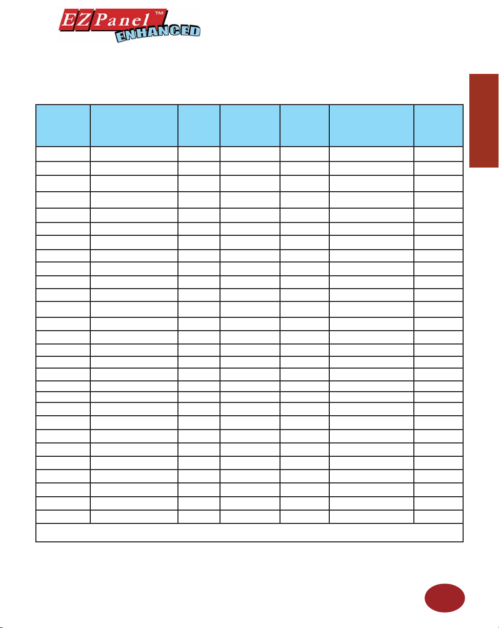
8-inch Color EZPanel Enhanced Models
In the table below are the 8-inch EZPanel Enhanced models. If using an option board connector, you cannot
use the PLC port at the same time to connect to another type PLC. The panel supports only one PLC driver
at a time.
Part Number Description
EZP-S8C-F 8” STN Color with Slim Bezel 512KB Yes, to 1 or 2 MB Yes All, plus EZ Ethernet NEMA 4, 4X
EZP-T8C-F 8” TFT Color with Slim Bezel 512KB Yes, to 1 or 2 MB Yes All, plus EZ Ethernet NEMA 4, 4X
EZP-S8C-FH 8” STN Color with Slim Bezel 512KB Yes, to 1 or 2 MB Yes
EZP-T8C-FH 8” TFT Color with Slim Bezel 512KB Yes, to 1 or 2 MB Yes
EZP-S8C-FS 8” STN Color with Slim Bezel 512KB Yes, to 1 or 2 MB Yes All, plus EZ Ethernet NEMA 1, FDA
*EZP-S8C-FSD 8” STN Color with Slim Bezel 512KB Yes, to 1 or 2 MB Yes All, plus DeviceNet NEMA 1, FDA
*EZP-S8C-FD 8” STN Color with Slim Bezel 512KB Yes, to 1 or 2 MB Yes All, plus DeviceNet NEMA 4, 4X
*EZP-T8C-FD 8” TFT Color with Slim Bezel 512KB Yes, to 1 or 2 MB Yes All, plus DeviceNet NEMA 4, 4X
*EZP-S8C-FSE 8” STN Color with Slim Bezel 512KB Yes, to 1 or 2 MB Yes All, plus Ethernet I/P NEMA 1, FDA
*EZP-S8C-FE 8” STN Color with Slim Bezel 512KB Yes, to 1 or 2 MB Yes All, plus Ethernet I/P NEMA 4, 4X
*EZP-T8C-FE 8” TFT Color with Slim Bezel 512KB Yes, to 1 or 2 MB Yes All, plus Ethernet I/P NEMA 4, 4X
EZP-S8C-FSH 8” STN Color with Slim Bezel 512KB Yes, to 1 or 2 MB Yes
*EZP-S8C-FSM 8” STN Color with Slim Bezel 512KB Yes, to 1 or 2 MB Yes All, plus MB+ NEMA 1, FDA
*EZP-S8C-FM 8” STN Color with Slim Bezel 512KB Yes, to 1 or 2 MB Yes All, plus MB+ NEMA 4, 4X
*EZP-T8C-FM 8” TFT Color with Slim Bezel 512KB Yes, to 1 or 2 MB Yes All, plus MB+ NEMA 4, 4X
*EZP-S8C-FSP 8” STN Color with Slim Bezel 512KB Yes, to 1 or 2 MB Yes All, plus Profi bus NEMA 1, FDA
*EZP-S8C-FP 8” STN Color with Slim Bezel 512KB Yes, to 1 or 2 MB Yes All, plus Profi bus NEMA 4, 4X
*EZP-T8C-FP 8” TFT Color with Slim Bezel 512KB Yes, to 1 or 2 MB Yes All, plus Profi bus NEMA 4, 4X
*EZP-S8C-FST 8” Color with Slim Bezel 512KB Yes, to 1 or 2 MB Yes All, plus ModBus TCP/IP NEMA 1, FDA
*EZP-S8C-FT 8” STN Color with Slim Bezel 512KB Yes, to 1 or 2 MB Yes All, plus ModBus TCP/IP NEMA 4, 4X
*EZP-T8C-FT 8” TFT Color with Slim Bezel 512KB Yes, to 1 or 2 MB Yes All, plus ModBus TCP/IP NEMA 4, 4X
*EZP-S8C-FSC 8” STN Color with Slim Bezel 512KB Yes, to 1 or 2 MB Yes All, plus CC Link NEMA 1, FDA
*EZP-S8C-FC 8” STN Color with Slim Bezel 512KB Yes, to 1 or 2 MB Yes All, plus CC Link NEMA 4, 4X
*EZP-T8C-FC 8” TFT Color with Slim Bezel 512KB Yes, to 1 or 2 MB Yes All, plus CC Link NEMA 4, 4X
*EZP-S8C-FSU 8” Color with Slim Bezel 512KB Yes, to 1 or 2 MB Yes ONLY Universal Ethernet NEMA 1, FDA
*EZP-S8C-FU 8” STN Color with Slim Bezel 512KB Yes, to 1 or 2 MB Yes ONLY Universal Ethernet NEMA 4, 4X
*EZP-T8C-FU 8” TFT Color with Slim Bezel 512KB Yes, to 1 or 2 MB Yes ONLY Universal Ethernet NEMA 4, 4X
*EZP-T8C-E 8” TFT Color with Slim Bezel 512KB Yes, to 1 or 2 MB Yes ONLY EZPLC NEMA 4, 4X
*Indicates NEW EZPanel Enhanced Models.
User
Memory
Field
Expandable User
RAM?
Nonvolatile
Flash Backup
Card Option
for Program
Backup?
PLC Drivers Upported? NEMA
All, plus AB DH+ and
Remote I/O
All, plus AB DH+ and
Remote I/O
All, plus AB DH+ and
Remote I/O
NEMA 4, 4X
NEMA 4, 4X
NEMA 1, FDA
Introduction
Introduction
7
Page 20
Editor Programming Software User Manual
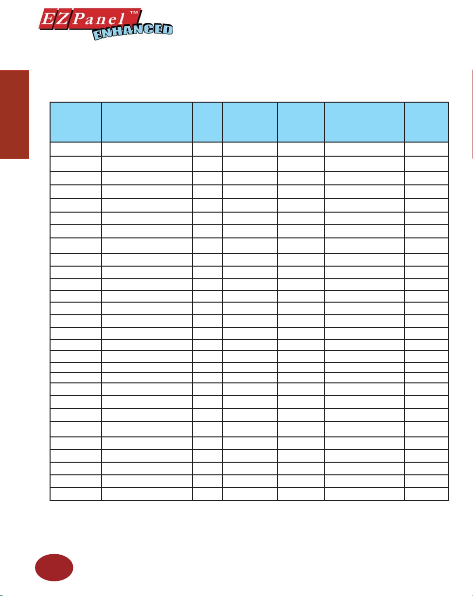
10-inch and 15-inch EZPanel Enhanced Models
In the table below are the 10-inch and 15-inch EZPanel Enhanced models. If using an option board connector,
you cannot use the PLC port at the same time to connect to another type PLC. The panel supports only
one PLC driver at a time.
Part Number Description
Introduction
EZP-T10C-F 10.4” TFT Color with Slim Bezel 512KB Yes, to 1 or 2 MB Yes All Serial Drivers NEMA 4, 4X
EZP-T10C-FH 10.4” TFT Color with Slim Bezel 512KB Yes, to 1 or 2 MB Yes
EZP-T10C-FS 10.4” TFT Color with Slim Bezel 512KB Yes, to 1 or 2 MB Yes All, plus EZ Ethernet NEMA 1, FDA
EZP-T10C-FD 10.4” TFT Color with Slim Bezel 512KB Yes, to 1 or 2 MB Yes All, plus DeviceNet I/O NEMA 4, 4X
EZP-T10C-FSD 10.4” TFT Color with Slim Bezel 512KB Yes, to 1 or 2 MB Yes All, plus DeviceNet I/O NEMA 1, FDA
EZP-T10C-FE 10.4” TFT Color with Slim Bezel 512KB Yes, to 1 or 2 MB Yes All, plus Ethernet I/P NEMA 4, 4X
EZP-T10C-FSE 10.4” TFT Color with Slim Bezel 512KB Yes, to 1 or 2 MB Yes All, plus Ethernet I/P NEMA 1, FDA
EZP-T10C-FSH 10.4” TFT Color with Slim Bezel 512KB Yes, to 1 or 2 MB Yes
EZP-T10C-FM 10.4” TFT Color with Slim Bezel 512KB Yes, to 1 or 2 MB Yes All, plus Modbus Plus NEMA 4, 4X
EZP-T10C-FSM 10.4” TFT Color with Slim Bezel 512KB Yes, to 1 or 2 MB Yes All, plus Modbus Plus NEMA 1, FDA
EZP-T10C-FP 10.4” TFT Color with Slim Bezel 512KB Yes, to 1 or 2 MB Yes All, plus Profi bus NEMA 4, 4X
EZP-T10C-FSP 10.4” TFT Color with Slim Bezel 512KB Yes, to 1 or 2 MB Yes All, plus Profi bus NEMA 1, FDA
EZP-T10C-FT 10.4” TFT Color with Slim Bezel 512KB Yes, to 1 or 2 MB Yes All, plus ModBus TCP/IP NEMA 4, 4X
EZP-T10C-FST 10.4” TFT Color with Slim Bezel 512KB Yes, to 1 or 2 MB Yes All, plus ModBus TCP/IP NEMA 1, FDA
EZP-T10C-FC 10.4” TFT Color with Slim Bezel 512KB Yes, to 1 or 2 MB Yes All, plus CC Link NEMA 4, 4X
EZP-T10C-FSC 10.4” TFT Color with Slim Bezel 512KB Yes, to 1 or 2 MB Yes All, plus CC Link NEMA 1, FDA
EZP-T10C-FU 10.4” TFT Color with Slim Bezel 512KB Yes, to 1 or 2 MB Yes ONLY Universal Ethernet NEMA 4, 4X
EZP-T10C-FSU 10.4” TFT Color with Slim Bezel 512KB Yes, to 1 or 2 MB Yes ONLY Universal Ethernet NEMA 1, FDA
EZP-T10C-E 10.4” TFT Color with Slim Bezel 512KB Yes, to 1 or 2 MB Yes ONLY EZPLC NEMA 4, 4X
EZP-T15C-FS 15” TFT Color with Slim Bezel 1MB Yes, to 1 or 2 MB Yes All, plus EZ Ethernet NEMA 1, FDA
EZP-T15C-FSD 15” TFT Color with Slim Bezel 1MB Yes, to 1 or 2 MB Yes All, plus DeviceNet I/O NEMA 1, FDA
EZP-T15C-FSE 15” TFT Color with Slim Bezel 1MB Yes, to 1 or 2 MB Yes All, plus Ethernet IP NEMA 1, FDA
EZP-T15C-FSH 15” TFT Color with Slim Bezel 1MB Yes, to 1 or 2 MB Yes
EZP-T15C-FSM 15” TFT Color with Slim Bezel 1MB Yes, to 1 or 2 MB Yes All, plus Modbus Plus NEMA 1, FDA
EZP-T15C-FSP 15” TFT Color with Slim Bezel 1MB Yes, to 1 or 2 MB Yes All, plus Profi bus NEMA 1, FDA
EZP-T15C-FST 15” TFT Color with Slim Bezel 1MB Yes, to 1 or 2 MB Yes All, plus Modbus TCP/IP NEMA 1, FDA
EZP-T15C-FSC 15” TFT Color with Slim Bezel 1MB Yes, to 1 or 2 MB Yes All, plus CC Link NEMA 1, FDA
EZP-T15C-FSU 15” TFT Color with Slim Bezel 1MB Yes, to 1 or 2 MB Yes ONLY Universal Ethernet NEMA 1, FDA
User
Memory
Field
Expandable User
RAM?
Nonvolatile
Flash Backup
Card Option
for Program
Backup?
PLC Drivers Upported? NEMA
All, plus AB DH+ and
Remote I/O
All, plus AB DH+ and
Remote I/O
All, plus AB DH+ and
Remote I/O
NEMA 4, 4X
NEMA 1, FDA
NEMA 1, FDA
8
Page 21
Features
Editor Programming Software User Manual
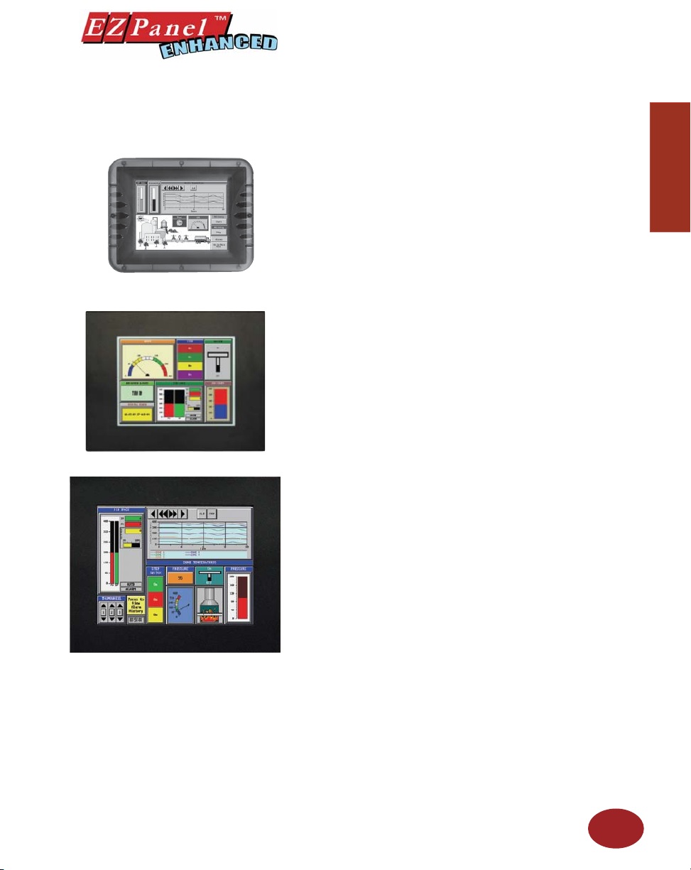
• Pre-built panel components for easy screen design
• Screen Objects such as: Toggle Switch, Slide Switch,
Selector Switch, Throw Switch, Thumbwheel Object, Meters,
PID Face plates, and Analog/Digital Clock
• Flash memory-based design for easy fi rmware upgrade
• Field expandable user RAM (not all models)
• Nonvolatile fl ash card option for user program backup
(not all models)
• Color models support 128-color palette for components and
bitmaps
• 16 shades of gray on monochrome models
• Multiple languages (up to 9)
• Two communications ports — Computer (RS-232C) and
PLC
(RS-232C, RS-422A, or RS-485A)
• Up to 999 screens
• Built-in clock and calendar or reference the PLC clock
• Built-in soft keypad for numeric and alphanumeric entry
• Password Protection for every touch object
• Passwords for up to 8 user groups
• 16 level undo and redo
• Import bitmaps
• Serial Printer support
• 40-character tag names allow you to use meaningful names
for PLC memory locations instead of cryptic PLC addresses
• New features including: overlapping of objects, free-sizing
of touch objects, Pick and Apply Attributes, display address
Introduction
Introduction
9
Page 22
Editor Programming Software User Manual
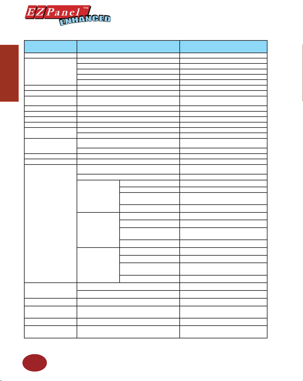
PLCs Supported by EZPanels
PLC Brand Model
EZAutomation EZPLC EZ Protocol
Allen Bradley
Introduction
Aromat Aromat Mewtocol COM
Control Techniques Unidrive 2-wire, 4-wire Binary
Control Technology
Corporation (CTC)
DeviceNet DeviceNet I/O DeviceNet I/O (OptionCard)
Ethernet Control Logic, Micro Logic, Compact Logic, GE Versamax Ethernet I/P, SRTP, DF1, Modbus TCP/IP
General Electric 90/30 and 90/70 Versamax SNPX/SNP
Mitsubishi
Modicon
Omron C200, C500, CQM1, CPM1, CPM2 Host Link
Profi bus Profi bus-DP Generic Profi bus DP(Option Card)
Direct Logic
Siemens
Square D Symax 300 Series CPU, 400 Series CPU Symax
Texas Instruments TI5X5 Series, TI505, TI545-1102, TI545-1104
Uni-Telway Telemecanique TSX 37 Micro UNI-TE (Version 1.1)
Other
Protocols
Supported
MicroLogix 1000/1200/1500, SLC500,5/01, /02, /03 DH 485/AIC/AIC+
MicroLogix 1000/1200/1500SLC 5/03, 5/04, and 5/05 DF1 Half Duplex/DF1 Full Duplex
Idec Idec Computer Link
984 CPU, Quantum 113 CPU, AEG Modicon Micro Series
110, CPU: 311-xx, 411-xx, 512-xx, 612-xx
DL205
DL305
DL405
H2- WinPLC (Entivity (Think & Do) V5.2 orlater, check for
SLC 504, PLC5 DH+ (Option Card)
PLC 5 DF1
PLC 2, 3, and 5 Remote I/O (with DH+ Plus Option Card)
CTC 2600, 2700, and 5100 CTC Binary
FX Series (all) FX, Direct
CC Link CC Link Protocol
Modbus RTU
984 Series, Qunatum Series Modicon Plus (Option Card)
DL105
DL105 K-Sequence
D2-230 K-Sequence
D2-240 K-Sequence; DirectNet
D2-250/D2-250 - 1/260
D2-240/250 w/DCM DirectNet
D3-330/330P DirectNet
D3-340 DirectNet
D3-350
D3-350 w/DCM DirectNet
D4-430 K-Sequence; DirectNet
D4-440 K-Sequence; DirectNet
D4-450
All with DCM DirectNet
Siemens S7 MPI Adaptor 3964R
Siemens S7_200 Siemens S7_200
version compatability
Entivity (Think & Do) Modbus RTU (Serial Port)
K-Sequence, DirectNet,
Modbus (Koyo Addressing)
K-Sequence; DirectNet;
ModBus (Koyo addressing)
K-Sequence; DirectNet;
ModBus (Koyo addressing)
K-Sequence; DirectNet;
ModBus (Koyo addressing)
TBP (Transparent ByteProtocol) or NITP
(Non-Intelligent Terminal Protocol)
10
Page 23
PLC Cable Part Numbers
Editor Programming Software User Manual
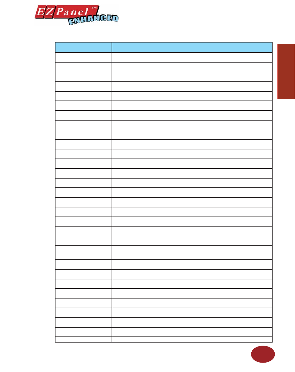
Cable Part Number Cable Description
EZP-CBL
EZP-2CLB
EZP-2CBL-1
EZP-3CBL
EZP-4CBL-1
EZP-4CBL-2
EZP-MLOGIX-CBL
EZP-SLC-232-CBL
EZP-PLC5-232-CBL1
EZP-DH485-CBL
EZP-90-30-CBL
EZP-MITSU-CBL
EZP-MITSU-CBL-1
EZP-S7MPI-CBL
EZP-OMRON-CBL
EZP-ARCOL-CBL
EZP-CTRLUNI-CBL
EZP-CTRLUNI-CBL-1
EZP-CTCBI-CBL
EZP-IDECM-CBL
EZP-MODUNI-CBL
EZP-MODRTU-CBL
EZP-S7200-CBL
EZP-SYMAX-CBL
EZP-TX505-CBL
EZP-IDECS-CBL
EZP-TX545-CBL
EZP-TX545-CBL1
EZP-MODRJ
EZP-PGMCBL Programming Cable
RS232C shielded cable to connect any EZPanel Enhanced to EZPLC. 15 pin D-shell male connector to 9 pin D-shell male connector.
10’ RS232C shielded cable to connect any EZPanel, Enhanced to DL05, DL06, DL105, DL205,
D3-350 or D4-450 CPU. 15 pin D-shell male connector to RJ 12 modular connector.
10’ RS232C shielded cable to connect any EZPanel Enhanced to a DL06, D2-250(-1) or D2-260
(bottom port) CPU. 15 pin D-shell male connector to 15 pin male HD.
10’ RS232C shielded cable to connect any EZPanel Enhanced to a D3-340 CPU top or bottom
port. 15 pin D-shell male connector to RJ11 modular connector.
10’ RS232C shielded cable to connect any EZPanel Enhanced panel to DL 405 (top port) CPU.
15 pin D-shell male connector to 15 pin D-shell male connector.
10’ RS 232C shielded cable to connect any EZPanel Enhanced to a D2-DCM, D3-350 (bottom
port), a D3-232-DCU installed on D3-333 or D3-340, or DL 405 (bottom point) CPU.
6’ shielded cable to connect any EZPanel Enhanced to an AB Micrologix 1000, 1200, or 1500
CPU. 15 pin D-shell male connector to 8 pin DIN connector
10’ RS232C shielded cable to connect any EZPanel Enhanced to an AB SLC 5/03, 5/04 or 5/05
CPU with DF-1 port. 15 pin D-shell male connector to 9 pin D-shell female connector.
10’ RS232C shielded cable to connect any EZPanel Enhanced to an AB PLC5 CPU with DF1
port. 15 pin D-shell male connector to 25 pin D-shell male connector.
10’ RS232C shielded cable to connect any EZPanel Enhanced to an AB SLC 500 CPU with a
DH485 port and 747-A/C Module.
10’ RS232C shielded cable to connect any EZPanel Enhanced to GE Fanuc Series 90/30, 90/70
serial port using SNPX protocol. 15 pin D-shell male connector to 15 pin D-shell male connector.
10’ RS422 shielded cable to connect any EZPanel Enhanced to Mitsubishi FX series CPU. 15
pin D-shell male connector to 25 pin D-shell male connector.
10’ RS422 shielded cable to connect any EZPanel Enhanced to Mitsubishi FX series CPU. 15
pin D-shell male connector to 8 pin min. din.
10’ shielded cable to connect any EZPanel Enhanced to Siemens Simatic S7 series CPU. 15 pin
D-shell male connector to 9 pin D-shell connector
10’ RS232C shielded cable to connect any EZPanel Enhanced to Omron C200 or C500 with
Hostlink protocol. 15 pin D-shell male connector to 25 pin D-shell male connector.
10’ RS232C shielded cable to connect any EZPanel Enhanced to Aromat PLC. 15 pin D-Shell
male connector to 5 pin mini DIN male connector.
10’ RS422 shielded cable to connect any EZPanel Enhanced to Control Techniques Unidrive
4-wire. 15 pin D-Shell male connector to 9 pin D-shell female connector.
10’ RS485 shielded cable to connect any EZPanel Enhanced to Control Techniques
Unidrive 2-wire. 15 pin D-Shell male connector to 9 pin D-shell female connector.
10’ RS232 shielded cable to connect any EZPanel Enhanced to Control Technology
Corportation (CTC). 15 pin D-Shell male connector to RJ12.
10’ RS485 shielded cable to connect any EZPanel Enhanced to IDEC Micro 3 PLC. 15
pin D-Shell male connector to 8-pin Mini DIN connector.
10’ RS485 shielded cable to connect any EZPanel Enhanced to Modicon Uni-Telway
Telemecanique TSX 37 Micro PLC. 15 pin D-Shell male connector to 8 pin mini DIN
connector.
10’ RS232C shielded cable to connect any EZPanel Enhanced to Modicon Modbus
RTU. 15 pin D-Shell male connector to 9 pin D-shell male connector.
10’ RS485 shielded cable to connect any EZPanel Enhanced to Siemens S7 200 PLC.
15 pin D-Shell male connector to 9 pin D-shell male connector.
10’ RS422 shielded cable to connect EZPanel Enhanced to Square-D symax. 15 pin
D-Shell male connector to 9 pin D-shell male connector.
10’ RS232C shielded cable to connect any EZPanel Enhanced connect to Texas Instrument 505 Series PLC. 15 pin D-Shell male connector to 9 pin D-shell female connector.
10’ RS232C shielded cable to connect any EZPanel Enhanced to IDEC Micro Smart
PLC. 15 pin D-Shell male connector to 8 pin mini DIN male connector.
10’ RS422 shielded cable to connect any EZPanel Enhanced to Texas Instrument 5451102 series PLC. 15 pin D-Shell male connector to 9 pin D-shell male connector.
10’ RS422 shielded cable to connect any EZPanel Enhanced to Texas Instrument 5451104 PLC. 15 pin D-Shell male connector to 9 pin D-shell female connector.
10’ RS232 Shielded Cable to connect any EZPanel Enhanced to Modicon Micro PLC.
15-pin D-shell male connector to RJ45 connector.
NOTE: See Appendix A for cable pinouts, or use the EZPanel Enhanced Editor Programming
Software (P/N EZP-PANELEDIT) Help Topics. For RS-422A connections to DirectLogic PLCs
also see Appendix A.
11
Introduction
Introduction
Page 24
Introduction
Editor Programming Software User Manual
EZPanel Enhanced Editor Programming
Software
EZPanel Enhanced models are confi gured with software running on an IBM
or compatible personal computer. This software is available through EZ
Automation, part number EZP-PANELEDIT. The panel can be confi gured
on-line or off-line (See page 3 for requirements).
Installing the Software
Perform the following steps to install the EZPanel Enhanced Editor
Programming Software onto your PC.
• Place the CD into your CD ROM drive.
The install program should launch automatically. If it does not,
perform the following steps.
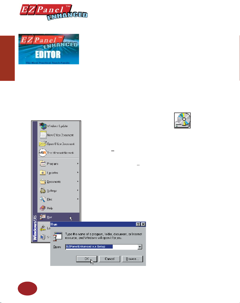
1 From Windows click on the Start Button, and then click on
2 At the prompt type D:\ (or your CD ROM drive) setup.exe
3 Click on the OK button to begin the installation. The EZPanel
• Follow the onscreen prompts to load the software. (Installation
Run from the menu. The Run dialog box will pop up.
or click on the Browse Button and fi nd the Setup.exe fi le
for EZPanel Enhanced Editor Programming Software.
Enhanced Editor Programming Software Installation Screen
will appear.
screens are shown, next page).
Installation Screens
12
Page 25
This icon will
appear on your
desktop after
installation.
Editor Programming Software User Manual
Introduction
Introduction
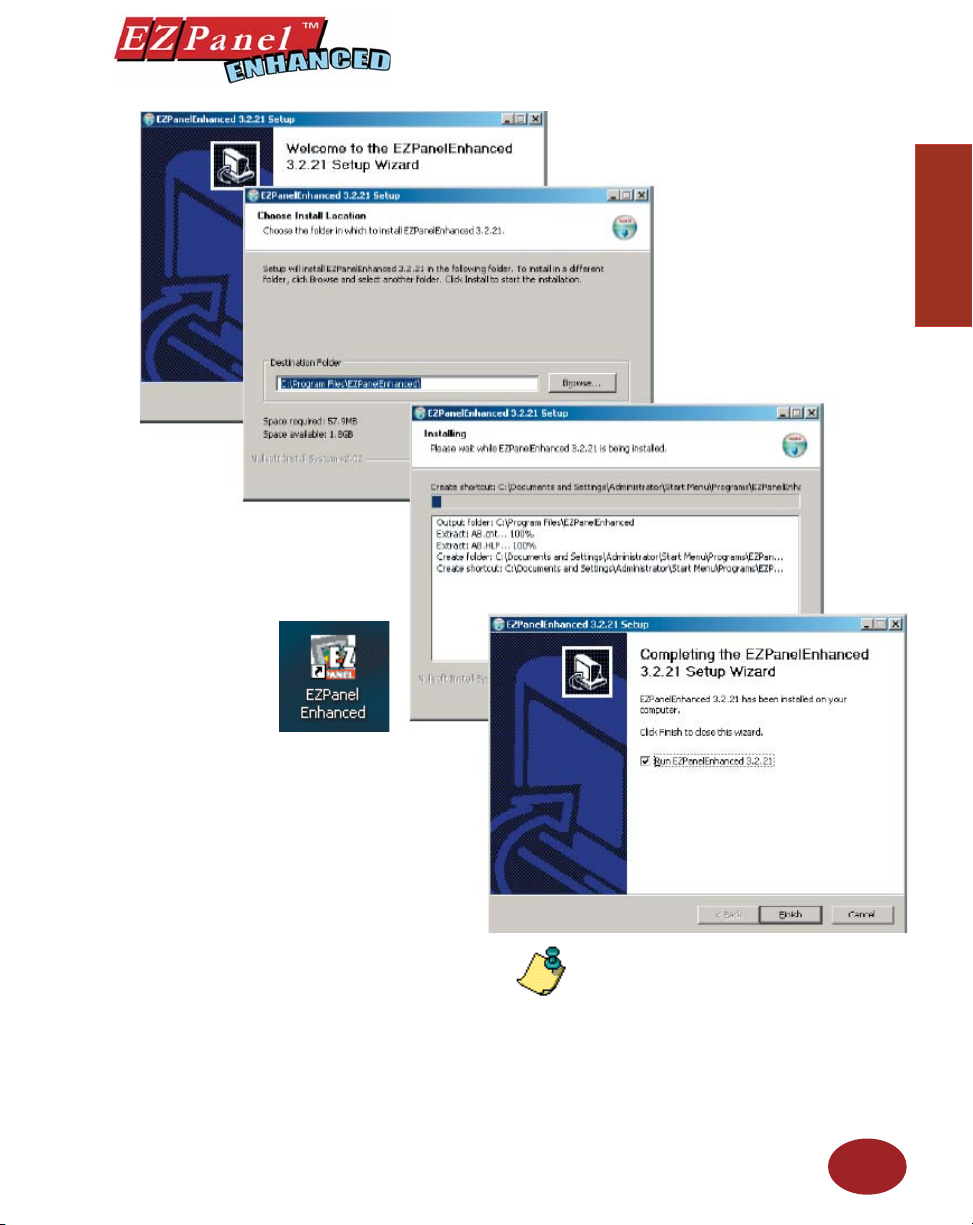
Simply follow the onscreen prompts to install
the software. You will select the destination
folder where your software program will be
installed. The default destination location
is C:\Program Files\EZPanel. If you wish to
select another destination, click on the Browse
button, choose the destination and click on
the Next > button.
Select whether to install the English or the
Spanish version of EZPanel Enhanced Editor
Programming Software. Click on the Next>
button.
To complete the installation, click on Finish
> button. That’s all there is to it! The
EZPanel Icon shown above will appear on
your desktop. Simply click on it to open the
Programming Software!
NOTE: A different version
number may appear
depending on which version
of the software you are
installing.
13
Page 26
Introduction
Editor Programming Software User Manual
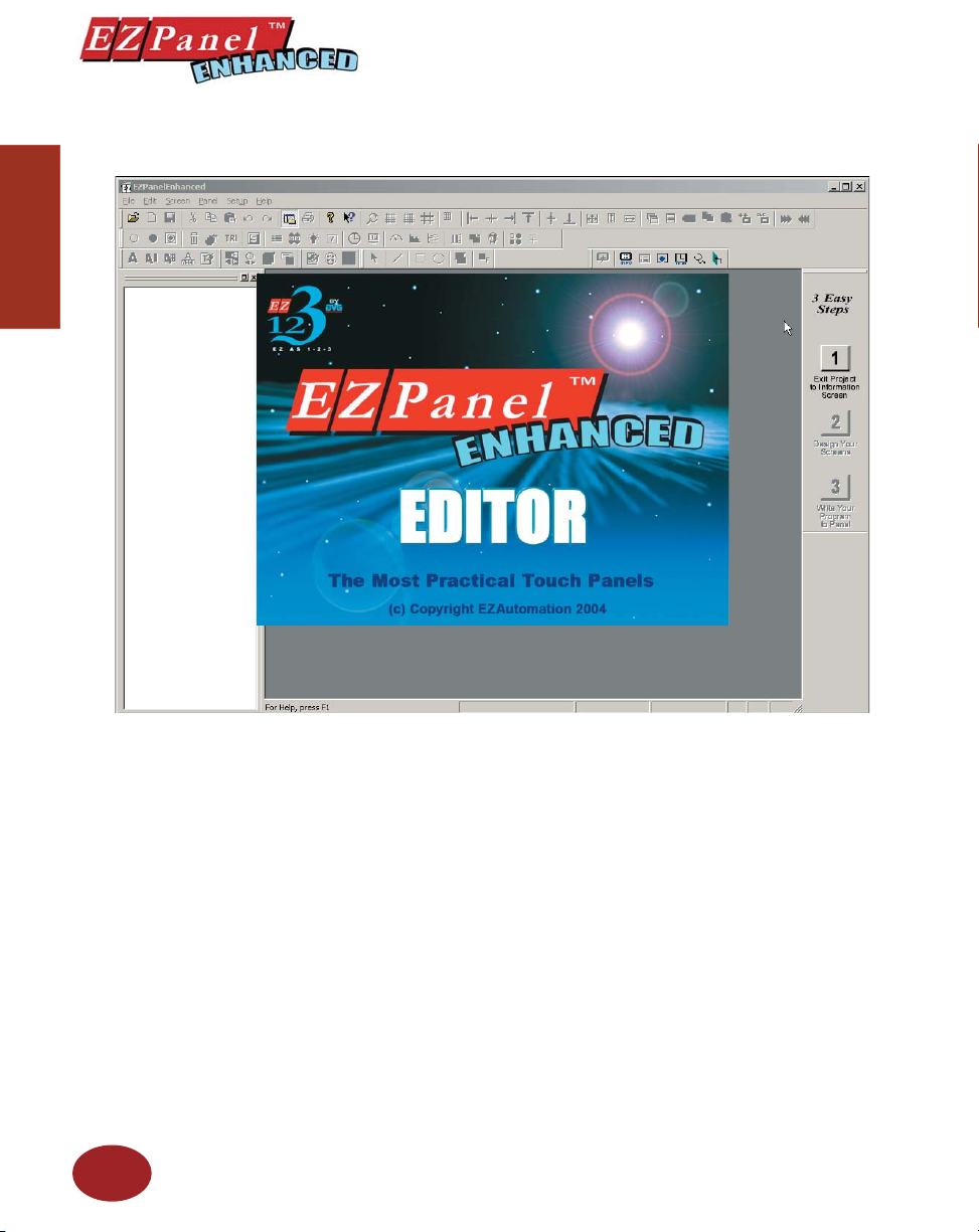
Once you’ve fi nished installing the software, the screen below should
appear. Open the software to view the EZLaunch Pad (see next page).
14
Page 27
Editor Programming Software User Manual
EZLaunch Pad
Overview
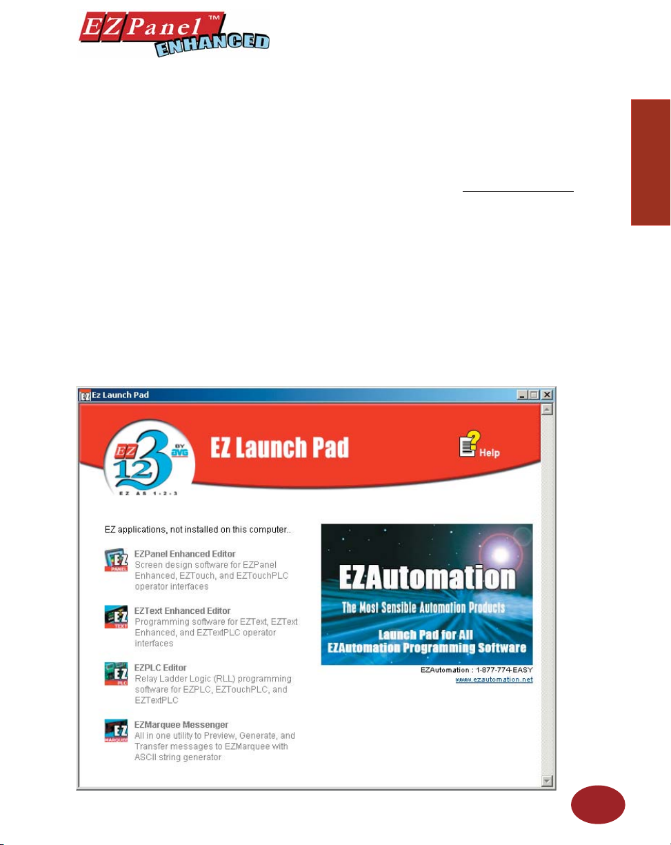
EZLaunch Pad is a convenient place to launch all EZAutomation software from one dialog box.
Distribution
EZLaunch Pad software is distributed with all EZAutomation software packages, such as EZPanel Editor, EZText,
EZPLC and EZMarquee String generator. The software is also available on www.ezautomation.net as a free
download.
Installation
To install this software please run the EZLaunchPadSetup.exe fi le. The software installs itself and places an icon
onto your desktop for your convenience.
Function
To use EZLaunch Pad software, click onto the EZLauch Pad icon. The software opens up a dialog box that lists
all the installed and non-installed EZAutomation software on your computer. You may click on any of the installed
programs to launch that software. The non-installed software is also listed but cannot be used.
If you have multiple versions of any installed EZAutomation software, the Launch Pad lists all versions for your
convenience.
Introduction
Introduction
15
Page 28

Introduction
Editor Programming Software User Manual
This page intentionally left blank.
16
Page 29

Tutorial
In this chapter....
— Confi gure a PLC
— Create a Project
2
Page 30
Tutorial — Confi gure PLC
Tutorial
Editor Programming Software User Manual
For the purposes of this Tutorial, we will be using a DirectLogic® 05 Series
Programmable Logic Controller (PLC), with K-Sequence Protocol. To
confi gure the PLC we are using DirectSOFT® Programming Software. The
purpose of this part of the tutorial is to show you how to confi gure your PLC
to communicate with an EZPanel Enhanced.
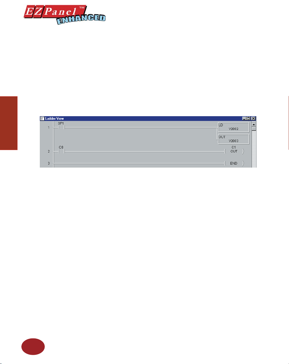
Connect the programming PC to the DL05 PLC. With DirectSOFT
Programming Software running on your PC, perform the following steps.
1. Enter the Ladder Logic as shown in the example below. These PLC
locations will be used by Tags that you will create in the EZPanel
Enhanced Editor Programming Software.
2. Save this program and transfer it to the PLC. Place the PLC in Run
Mode.*
18
3. Exit DirectSOFT.
For this tutorial, we will be connecting the panel to PLC Port 1 of a
DL05 (K-Sequence, 9600 Baud, Odd Parity). These are the settings
that will be used when setting up the panel communications.
You have now confi gured the PLC to communicate with an EZPanel
Enhanced Project that you will create in the next section of this
tutorial.
The following is a project tutorial. You’ve already confi gured your PLC to
*The mode switch of all DirectLogic PLCs must be in (TERM) position in
order for the EZPanel Enhanced to communicate with the PLC. Also, if it is
necessary for the Ladder Logic of the PLC to be protected by a Password,
a multi-level password must used. Please refer to your PLC user manual
to see if your PLC supports this feature.
Page 31
Editor Programming Software User Manual
Tutorial — Create a Project
work with the EZPanel Enhanced project you will be creating in this section.
Now we’ll take you through the process of creating a new project, placing
objects on the screen, and transferring a project to EZPanel Enhanced. This
should help familiarize you with the EZPanel Enhanced Editor Programming
Software environment.
Let’s assume you have the programming software installed on your PC (if
you don’t, go back to page 12 and install now). Connect EZPanel Enhanced
to your PC using the P/N EZP-PGMCBL cable. Connect EZPanel Enhanced
to your PLC using the appropriate panel to PLC cable.
Introduction
Step 1
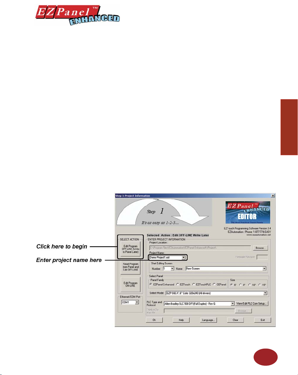
In Step 1, Project Information, you will be setting up your project by
entering project information.
1. From the Project Information screen, click on the Edit Program
OFF-LINE (Write to Panel Later) button.
2. Under Project Name, type in Demo Project 1. Press Enter. The
primary EZPanel Enhanced Program fi le has a “ .ezt” suffi x.
3. Under Start Editing Screen, leave the screen number as 1. Click in
the fi eld next to Name. Replace New Screen by typing in Numeric
Entry Screen.
Tutorial
19
Page 32
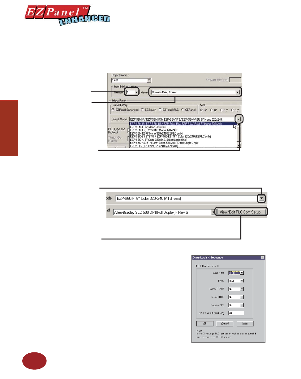
Enter Screen Number.
Type in “Numeric Entry
Screen” here.
Click on DOWN arrow to
Tutorial
view Panel Types and select
the Part Number/Model Type
you are using.
Click on DOWN arrow to
view PLC Type and Protocol
and select the type you are
using.
Editor Programming Software User Manual
4. Click on the DOWN arrow to the right of the Panel Type fi eld to view
choices. Select the Panel Type you are using.
5. Click on the DOWN arrow to the right of PLC Type and Protocol to
view the list. For the purpose of this Demo Program, select DirectLogic
K-Sequence. (We are using a DirectLogic DL05 PLC with K-Sequence
Protocol.)
To set PLC Attributes, click
on this button. A dialog
box particular to the type
PLC and Protocol you have
selected will appear.
20
6. Click on the View/Edit PLC Com
Setup to edit the PLC Attributes.
Set the attributes to match those
in the DirectLogic K-Sequence
attributes dialog box shown to the
right. Click OK. (These settings
must match the PLC Com Port
settings. Check your PLC User
Manual for port settings for your
particular PLC.)
Page 33
Editor Programming Software User Manual
Step 2
This software option remembers
the last Data Type used, and
it becomes the Default Data
Step 1 is complete!
You are now ready for Step 2, Design Your Screens. In Step 2 we will
place 4 objects on the screen. You have already confi gured your PLC ladder
logic for this Demo Project in the fi rst part of the tutorial.
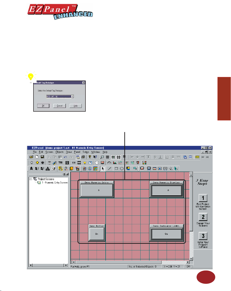
The EZPanel Enhanced Editor Programming Software working environment
is shown below. Tool bars provide easy access to all major programming
functions and features. The objects shown below represent the touch buttons
and displays that will be transferred to the panel and communicate with the
PLC when this tutorial is completed.
PROGRAMMING TIP: Before you begin placing objects on the programming
screen, click on Edit > Default Tag Data Type and select BCD_INT_16.
By selecting the default data type as BCD_INT_16 here, you won’t have to
select it later when confi guring the tag details for the objects. Please note,
however, that if the data type for an object requires something other than
the default data type you have selected, it will show the required data type
(i.e., Discrete).
1. Click on Objects > Numeric Entry. The following screen will
appear.
These are the four objects you are
about to confi gure in this tutorial.
Introduction
Tutorial
21
Page 34

Tutorial
Editor Programming Software User Manual
2. Click on the box in front of Label Text to activate the object label.
PLEASE NOTE: If your
panel is connected to multiple
PLCs, use the Station Number
to address a specifi c PLC. For
example: 2–V2002 would
address the PLC Station
Number 2.
22
3. In the fi eld next to Label Text, type in Demo Numeric Entry as shown
above.
4. Click in the fi eld next to Tag Name and type in NUMERIC ENTRY.
Press Enter. The following screen will appear.
5. In the fi eld next to Address String, type in V2002, as shown above.
Select BCD_INT_16 for the Data Type. Click OK.
6. Click on the Protection tab. The following screen will appear.
Page 35
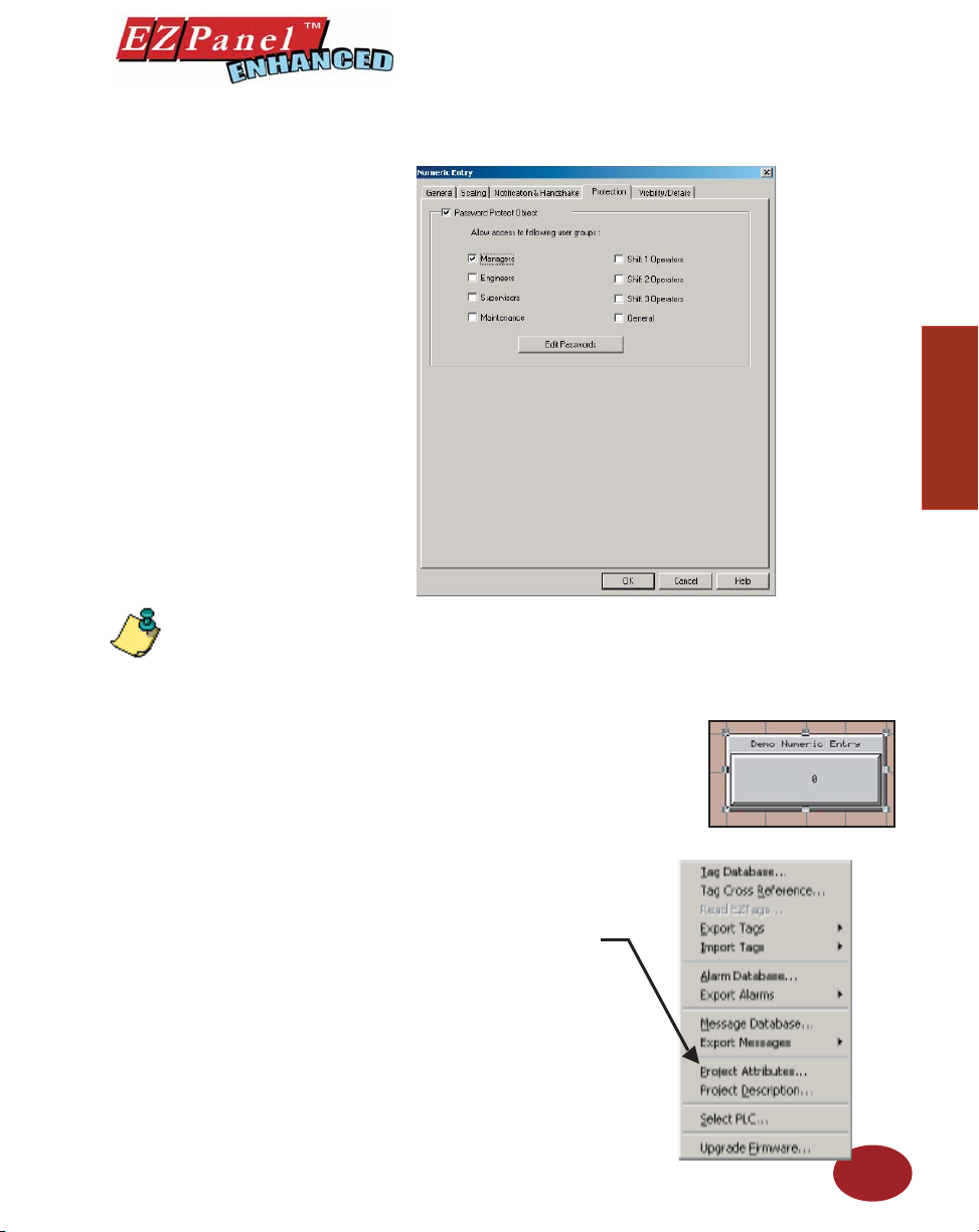
Editor Programming Software User Manual
NOTES ON RESIZING
AN OBJECT:
Drag the object to move, or drag
a handle to resize, the object.
The pointer changes to a fourway arrowhead (for moving), or
a two-way arrow (for resizing).
7. Click on the box in front of Password Protect Object, and then click
on the box in front of Managers. Click on OK.
8. A cross-hair cursor will appear on the programming screen. Position
cross-hair where you want the object to appear, and click once.
9. Grab the object by a handle and drag
to resize it until the label displays in its
entirety, as shown to the right.
Introduction
Tutorial
Dragging a side handle
changes the width or height
only; dragging a corner handle
changes the width and height
simultaneously.
10. Now go to the Main Menu Bar and click
on Setup > Project Attributes.
From the Main Menu Bar, click
on Setup > Project Attributes >
Passwords to enter the password
for the Numeric Entry Object.
(You may have noticed that on the
Numeric Entry Object Protection
tab, there is a button that says
Edit Passwords. You can use this
button to enter the password for
the object, but in this tutorial, we
wanted to provide you with an
example of how Project Attribute
confi guration relates to object
confi guration.)
23
Page 36
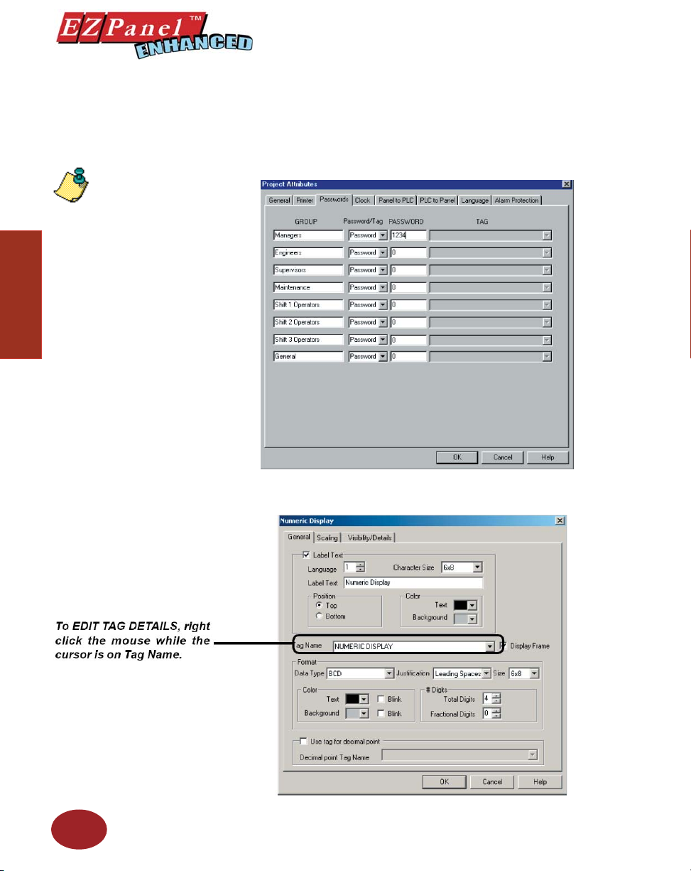
Tutorial
Editor Programming Software User Manual
11. Click on the Passwords tab. Under PASSWORD for the GROUP,
Managers, type in “1234”. Click OK.
12. Next, we’ll create a Numeric Display object. Click on Objects >
Numeric Display. The following dialog box will appear.
Please Note: Once the password
is entered for Managers, all
objects that you confi gure for
Protection at the “Manager”
level, will now require the
Password “1234”.
24
13. Click on the box in front of Label Text to activate the object label.
14. In the fi eld next to Label Text, type in Demo Numeric Display.
Page 37
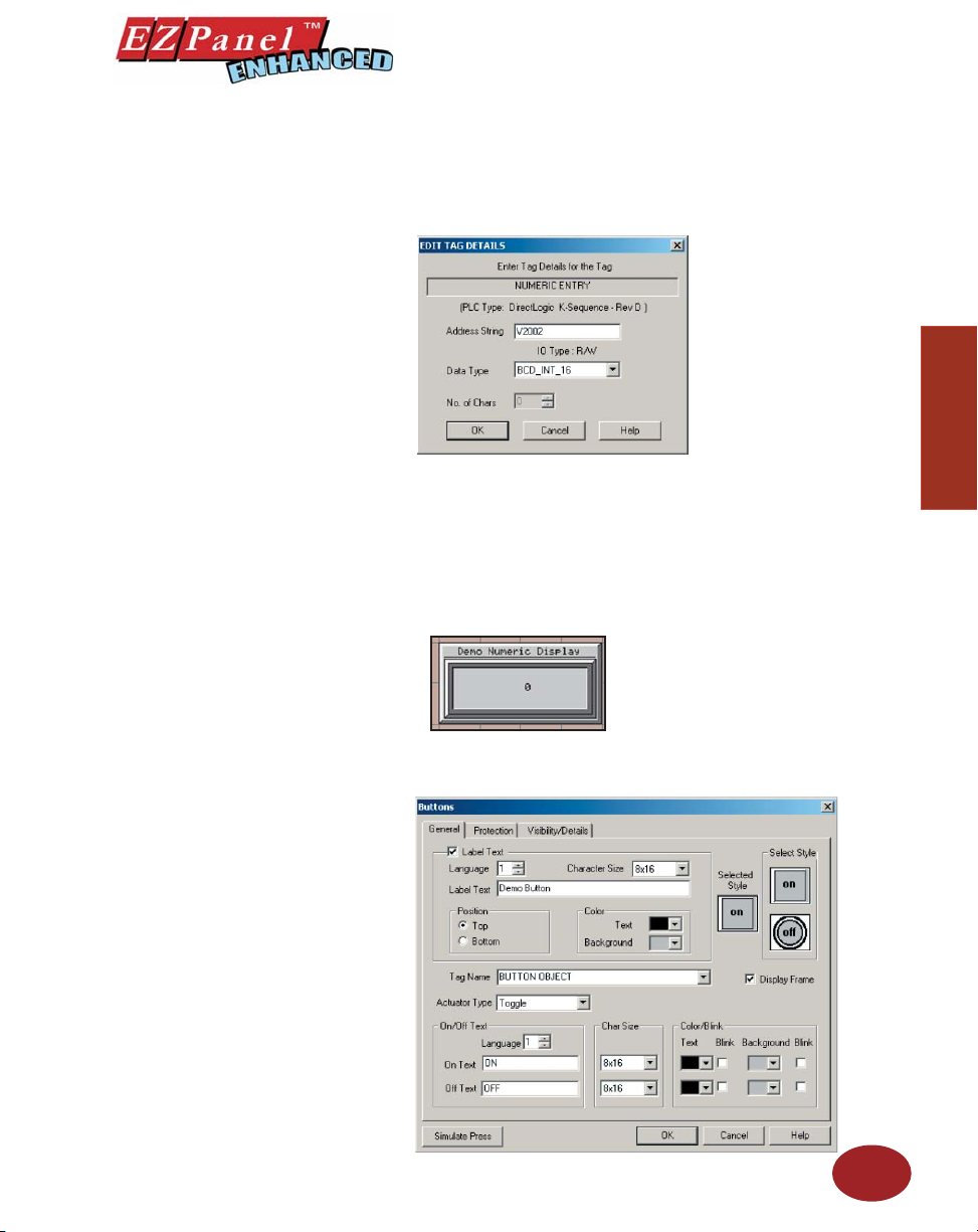
Editor Programming Software User Manual
15. Click in the fi eld next to Tag Name and type in NUMERIC DISPLAY.
Press Enter. The following screen will appear.
16. In the fi eld next to Address String, type in V2003, as shown above.
Select BCD_INT_16 as the Data Type. Click OK.
17. A cross-hair cursor will appear on the programming screen. Position
cross-hair where you want the object to appear, and click once.
18. Grab the object by a handle and drag to resize it until the label displays
in its entirety, as shown below.
19. Next, we’ll create a Button object. Click on Objects > Buttons. The
following dialog box will appear.
Introduction
Tutorial
20. Click on the box in front of Label Text to activate the object label.
25
Page 38
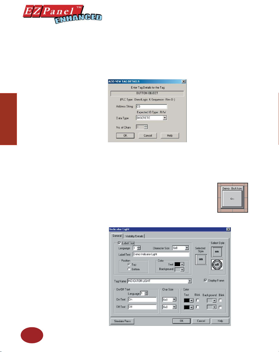
Tutorial
Editor Programming Software User Manual
21. In the fi eld next to Label Text, type in Demo Button.
22. Click in the fi eld next to Tag Name and type in BUTTON OBJECT.
Press Enter. The following screen will appear.
23. In the fi eld next to Address String, type in C0, as shown above. The
Data Type will remain as DISCRETE. Click OK.
24. A cross-hair cursor will appear on the programming screen. Position
where you want the object to appear (under the Numeric Entry object),
and click once.
25. Grab the object by a handle and drag to resize it until the label displays
in its entirety, as shown to the right.
26
26. Next, we’ll create an Indicator Light object. Click
on Objects > Indicator Lights. The following dialog
box will appear.
27. Click on the box in front of Label Text to activate the
object label.
Page 39
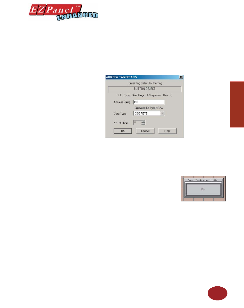
Editor Programming Software User Manual
28. In the fi eld next to Label Text, type in Demo Indicator Light as shown
above.
29. Click in the fi eld next to Tag Name and type in INDICATOR LIGHT.
Press Enter. The following screen will appear.
30. In the fi eld next to Address String, type in C1, as shown above. The
Data Type will remain as DISCRETE. Click OK.
31. A cross-hair cursor will appear on the programming screen. Position
the cross-hair where you want the object to appear (under the Numeric
Display object), and click once.
32. Grab the object by a handle and drag
to resize it until the label displays in its
entirety, as shown to the right.
Introduction
Tutorial
33. Click on File > Save Project.
You’ve just completed Step 2, Design Your Screens! Now we will
transfer Demo Project 1 to EZPanel Enhanced.
You are now ready for Step 3, Write Your Program to Panel. Demo Project
1 should look similar to that shown below.
1. Click on the 3 button (Write Your Program to Panel) as shown in the
graphic below.
2. Click on the Start button at the bottom of the Write Program to Panel
dialog box to begin transferring the project to the panel.
3. Your user program, Demo Project 1, should now be written to the
EZPanel Enhanced, and the screen you have created should be
displayed on the panel.
27
Page 40
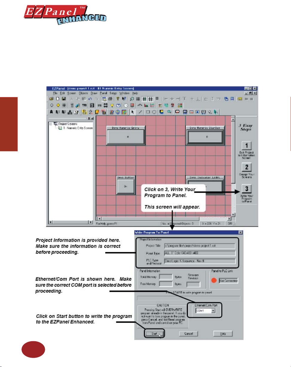
Tutorial
Editor Programming Software User Manual
Step 3
4. Panel Information will be updated with information it receives from
establishing a link with the panel and the PLC.
5. To test the link, press the Demo Numeric Entry button on your EZPanel
Enhanced screen. A popup keypad similar to the one shown below
should display.
6. Enter the Password “1234” on the keypad. Press Enter.
28
Page 41
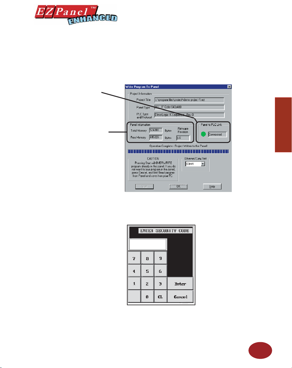
Editor Programming Software User Manual
The Panel to PLC Link will
display a green dot next to
the “Connected” message to
indicate that a link between the
panel and PLC is established.
Panel Information will display
the Total and Free Memory in
Bytes. It will also display the
Firmware Revision number
— the revision of the EZPanel
Enhanced internal software.
7. Another popup keypad similar to the one shown below will display.
8. Enter a number on the keypad by pressing the number keys. Press
Enter. The keypad will disappear and the number you entered should
appear on the Demo Numeric Display on your panel screen.
9. Press the Demo Button on your panel screen. It will change from
Off to On. The Demo Indicator Light should change from Off to On,
also.
Introduction
Tutorial
29
Page 42
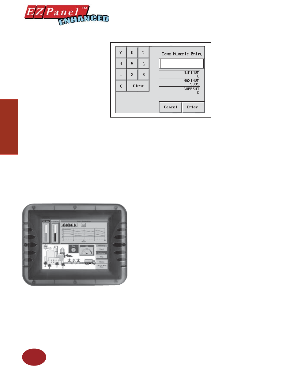
Editor Programming Software User Manual
You’ve just completed Step 3, Write Your Program to Panel!
Tutorial
You have now successfully confi gured a PLC, created a user program,
transferred it to the EZPanel Enhanced and established communication
between the PLC and panel.
This simple tutorial has taken you through the major steps to creating a
working link between your application and an EZPanel Enhanced. Of course,
there are almost unlimited capabilities for creating a program unique to
your application!
Changes are easy, too. Create your own Demo project based on this one,
adding color, password protection, and dynamic graphics, for instance.
EZPanel Enhanced and EZPanel Enhanced Editor Programming
Software are practical, versatile— and best of all — make it “EZ”
for you to create a dynamic interface for your application!
30
Page 43

Project Setup
In this chapter....
— ON-LINE and OFF-LINE Projects
— Project Setup
— Entering Project Information (Step 1)
— Designing Screens (Step 2)
— Write Your Program to Panel (Step 3)
3
Page 44

Project Setup
Editor Programming Software User Manual
Decide now if you want to work ON-LINE or
OFF-LINE...
You may create a new project on your PC by working off-line (not connected
to an EZPanel Enhanced). You may also work on-line with an EZPanel
Enhanced unit to make changes to an existing project.
Working off-line you may use EZPanel Enhanced Editor Programming
Software to design your EZPanel Enhanced unit in your offi ce or home — or
even while traveling. Your project becomes as portable as your laptop, and
your EZPanel Enhanced is not “down” while you are redesigning or making
modifi cations as your unique application needs grow or change. Your project
may be transferred to the EZPanel Enhanced at any time. The transfer
function allows you to select a project to be transferred to the Panel.
Working on-line is unique to EZPanels. Working in this mode allows you
to make quick fi xes or design changes to an installed EZPanel Enhanced
and its existing program. You can eliminate a step or two and save time by
transferring these changes directly to the current opened screen. Now you
can see the effect of the screen design changes you have made immediately,
eliminating the traditional “edit-compile-download” cycle. Simply click on
Save Screen or Save Project and all changes on the current opened
screen will immediately be saved in the EZPanel Enhanced.
Project Setup
We recommend you go through the tutorial beginning on page 17
of this manual. You’ll see how easy it is to get up and running!
32
Most users will employ both methods at one time or another, but whether
working off-line or on-line — you will certainly appreciate the versatility
and accessibility provided by EZPanel Enhanced and its easy-to-use
programming software.
The next section takes you through the steps necessary to create a
project and transfer it to EZPanel Enhanced. EZPanel Enhanced Editor
Programming Software simplifi es this process by using Windows-based
architecture and lots of popup and pull down selections that guide you
through the process to quickly build your screens and get you up and
running in no time at all!
Page 45
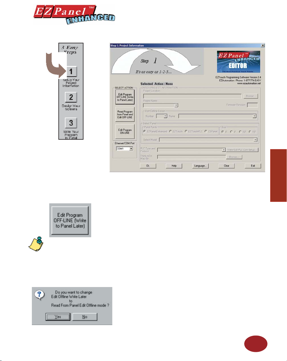
Editor Programming Software User Manual
Step 1 Project Information
SELECT ACTION
Project Setup
Edit Program OFF-LINE
(Write to Panel Later)
NOTE: If you change your mind
and click on another SELECT
ACTION button, a “confirm
action” message will appear, just
to make sure that this is what
you intended to do. Click on Yes
or No.
Under SELECT ACTION, click on one of the three “working mode buttons.”
If you want to work off-line (not connected to an EZPanel Enhanced), click
on the button labeled Edit Program OFF-LINE (Write to Panel Later). You
will use this mode when creating a new project.
1. From Project Information screen, click on the Edit Program
OFF-LINE (Write to Panel Later) button.
2. Click on the Browse button if you want to navigate to another
Directory or Folder where you will store your project. If you want
to accept the default folder (where EZPanel Enhanced Editor
Programming Software resides), just enter the name of your new
project in the empty fi eld under Project Name.
3. Under Start Editing Screen, leave the screen number as 1. Click
in the fi eld next to Name to highlight New Screen. Replace this
by typing in the name of your fi rst screen. If you haven’t decided
on a name, just leave it as is, you can change it later.
33
Page 46
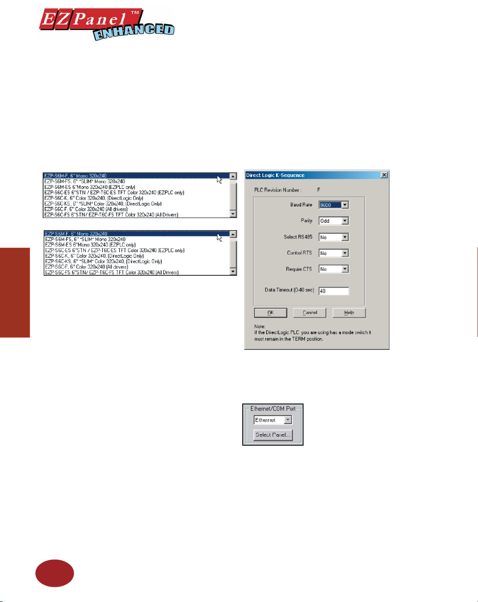
Editor Programming Software User Manual
Project Setup
4. Click on the DOWN arrow to the right of the Panel Type fi eld to
view choices. Select the Panel Type you are using.
5. Click on the DOWN arrow to the right of PLC Type and Protocol to
view the list. Select the PLC Type and Protocol you are using.
6. Click on the View/Edit PLC COM Setup to edit the PLC Attributes.
A dialog box will appear that is particular to the type of PLC you
have selected in the previous step. Set the attributes to match
your PLC. Click OK.
34
7. You should now be back to the Project Information screen. Check
to ensure that your Ethernet/COM Port is set to match your PC
(COM1, COM2, COM3 or COM4), or, if you want an Ethernet
connection, select Ethernet. A Select Panel button will appear
(as shown below).
8. Click on the Select Panel button to begin Ethernet
confi guration.
Please note: For help with Ethernet confi guration refer to
the Ethernet Option Card Manual, P/N EZP-ETHERNET-M, or
Ethernet Help topics.
9. When finished with Ethernet Configuration, click on the OK
button.
Page 47
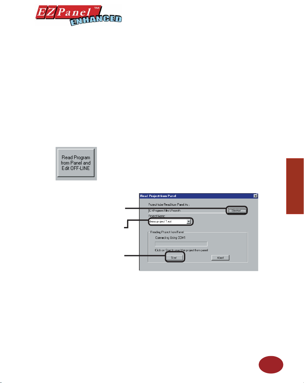
Editor Programming Software User Manual
Read Program from Panel
and Edit OFF-LINE
If not using the default
directory, click on the Browse
button to go to directory and
folder where project will be
stored.
Select or enter Project Name.
10. You will return to the Project Information screen, click on the
OK button to accept all settings.
You are now ready to begin confi guring your fi rst screen.
If you are connected to a panel and want to transfer a project from the
panel to your EZPanel Enhanced Editor Programming Software for editing,
click on the Read Program from Panel and Edit OFF-LINE button. Any
changes you make to the project will not take effect until you write the edited
project to your panel.
1. From the Project Information screen, click on the Read
Program from Panel and Edit OFF-LINE. The following screen
will appear.
2. Click on the Browse button if you want to navigate to another
Directory or Folder where you will store your program. If you want
Project Setup
Click on Start button to Start
Reading Project from Panel or
Abort to quit.
to accept the default folder (usually where the EZPanel Enhanced
Editor Programming Software resides), just enter the name that
you desire for the project you are about to Read in the empty
fi eld under Project Name.
3. Click on the Start button to start reading the project from the
panel.
4. A progress bar will appear, along with a text message, showing
you the status of the panel read.
5. When fi nished, click OK. You will be taken back to the Project
Information Screen. Notice that the project name entered now
35
Page 48
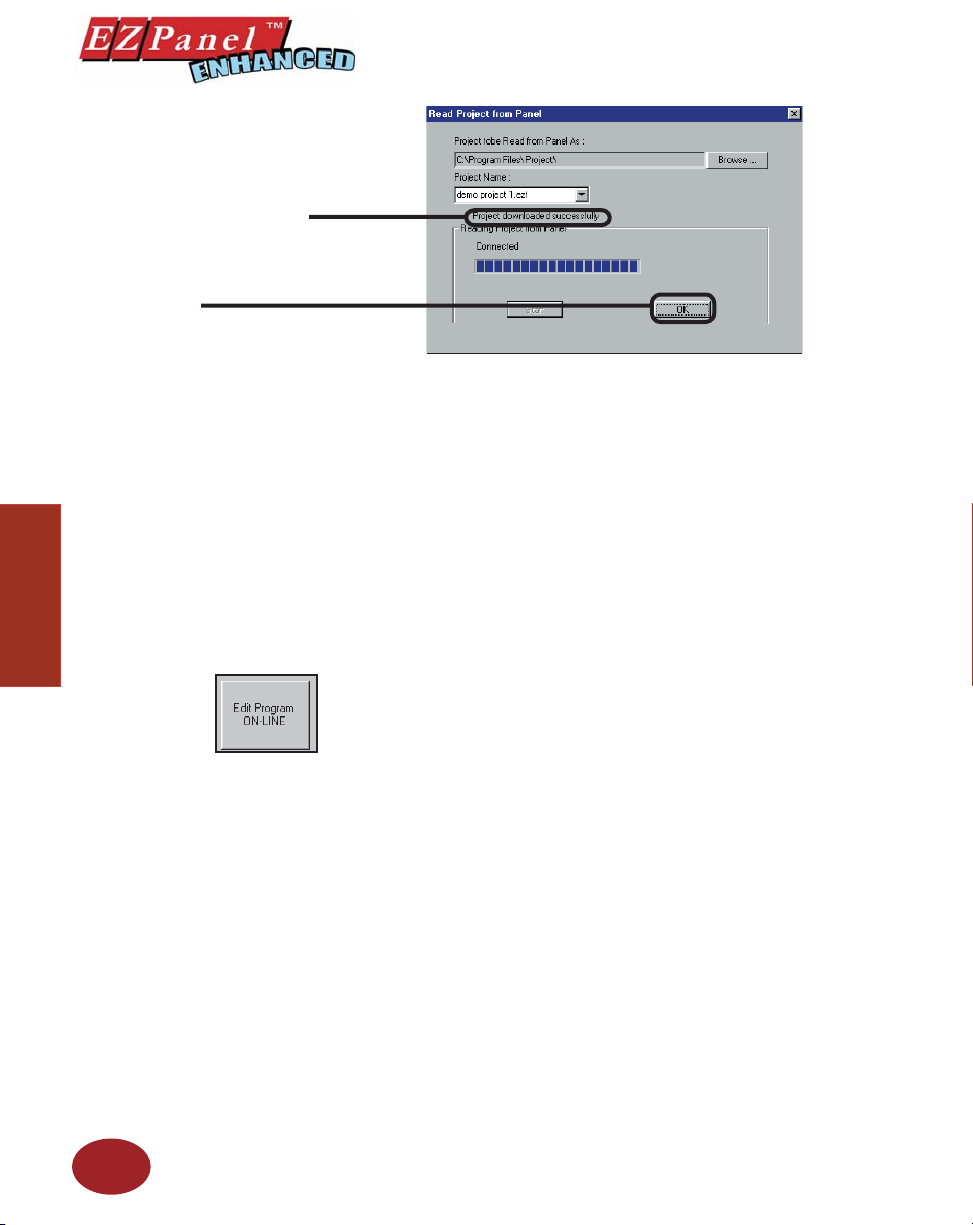
The message “Project
downloaded successfully” will
appear when the program has
fi nished downloading.
Click on OK to exit
screen.
Editor Programming Software User Manual
appears under Project Name in this screen.
Edit Program ON-LINE
Project Setup
6. Under Start Editing Screen, the Name and Number of Screen
number 1 will appear. If you want to begin editing another screen,
click on the down arrow next to Name or Number and select.
7. Click on the OK button to begin editing. You will go to the EZPanel
Enhanced Editor Main Programming Screen. You are now ready
to edit the selected screen.
The third choice available is to make changes to the project while online.
Click on the button labeled, Edit Program ON-LINE. The changes are
effective each time Save Screen or Save Project is selected, reducing
downtime. Click on Save Screen or Save Project and the changes will
appear on the panel screen immediately. This is recommended when you
need to make changes quickly to an existing user program without shutting
down the system.
1. From the Project Information screen, click on the button
labeled, Edit Program ON-LINE. The Panel Type, PLC Type,
and Firmware Revision of the panel will soon display.
2. Under Start Editing Screen, screen Number 1 will appear with
that screen’s Name. If you want to begin editing a screen other
than Number 1, click on the down arrow next to the Number fi eld
or the down arrow next to the Name fi eld to select the screen you
want to edit.
3. Click on OK. The screen you have selected will open on the
main programming screen for you to make changes.
36
4. Click on Save Screen to download changes to the screen
immediately. Click on Save Project to transfer all changes,
including project attributes and databases. They will be
immediately downloaded to the panel.
Page 49
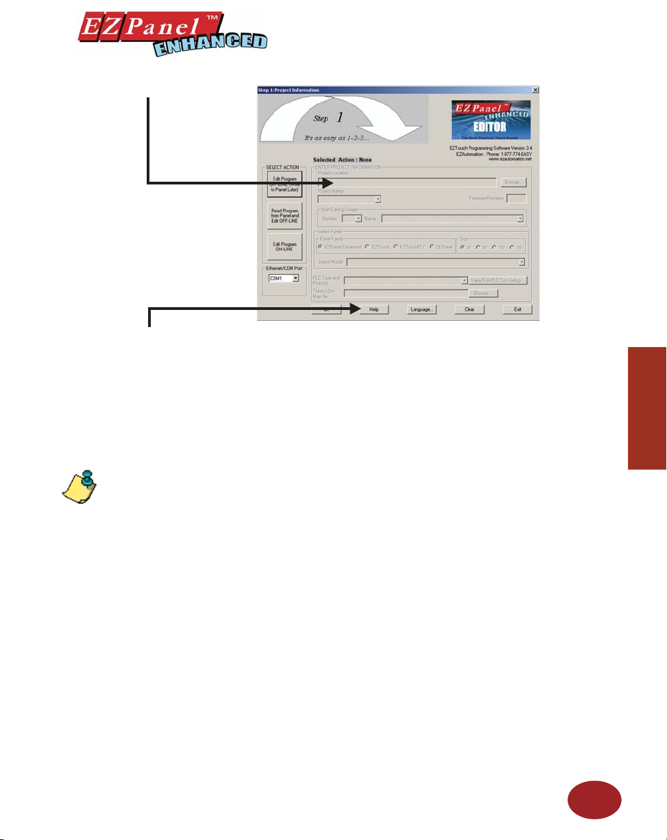
Editor Programming Software User Manual
A QUICK REVIEW for “ ENTER PROJECT INFORMATION”
Click on the Help Button at anytime for help.
Click on Clear to clear your entries
and start over.
Click on Exit to quit without saving
your selections, or click on OK to
save and begin editing.
NOTE: Panels with an option
card installed will have an “C, D,
E, H, M, P, T, or U” on the end of
the model part number to indicate
this. The program loader doesn’t
list these under Panel Type, so
just select the model part number
without the “C, D, E, H, M, P,
T, or U” that is closest to your
panel part number. See step 8,
next page.
Under ENTER PROJECT INFORMATION you will perform all or some of the
following actions (depending upon the working mode you have selected):
1. Project Location will default to the directory where the EZPanel
2. Under Project Name, click on the down arrow to view saved
3. Start Editing Screen allows you to select the screen that you
If you are connected to the panel (editing project on-line), the
Software program is stored. If your project resides in another
location, click on the Browse button to navigate to a different
folder.
projects or enter the new project name.
want to begin editing. To have the project open to the screen you
wish to edit, click on the down arrow to select the Name or the
Number of the screen. If it is a new project, the screen will default
to screen 1 with <New Screen> in the Name fi eld. Replace this
with whatever name you wish or wait until later and rename.
4. The fi eld Panel Type, allows you to select or change your panel
type.
Firmware Revision of the panel’s internal software will be
Project Setup
37
Page 50

Editor Programming Software User Manual
displayed.
Please NOTE:
PLC compatibility is always being
updated. If you don’t see your
type PLC and protocol, visit our
website at www.EZAutomation.
net to see if your PLC driver is
now available to download.
Project Setup
5. PLC Type and Protocol allows you to further defi ne your project
by selecting the PLC used in your application and the protocol
it uses. Click on the down arrow for a list of the available PLC
types.
6. Click on the View/Edit PLC COM Setup button to display the
PLC Attributes. The attributes screen particular to the PLC and
Protocol type you have selected will appear. You may change
attributes from this screen.
7. If you are using a Think-n-Do Map File for Automation Direct,
click on the Browse button to go to the directory or folder where
the map fi le resides.
The map fi le is simply a text delimited fi le that resides in any
Think-n-Do project. The EZPanel Enhanced Editor is set up to
pull tag names from your Think-n-Do project. This frees the user
from having to remember these tag names.
The map fi le will load into the project’s Tag Database. Tag
Database Log View will open if there are problems. You may
correct any problems from within the Think-N-Do map fi le or the
Tag Database.
8. If you are using an EZPanel Enhanced unit with an Option Card
installed, the Model Part Numbers for your unit have a “C, D, E,
H, M, P, T, or U” on the end to designate “C” for Mitsubishi CC
Link, “D” for Generic DeviceNet I/O, “E” for Generic Ethernet
I/P, “H” for Allen Bradley Data Highway Plus/Remote I/O, “M” for
Modicon Modbus Plus, “P” for Siemens Profi bus, “T” for Modicon
Modbus TCP/IP, “U” for Universal Ethernet (Ethernet/IP, DF1
over Ethernet, Modbus TCP/IP, and GE SRTP. These option
card designation letters do not appear on all model types where
an option card is available when you are selecting your Panel
Typ e on the Project Information screen. Just click on the model
part number without the “C, D, E, H, M, P, T, or U” on the
end that matches your panel size. In other words, the program
loader doesn’t see any differences in panel type between an EZS8C-FH (with A-B DH+ option card installed) and an EZ-S8C-F,
so you will select ALL, 8” Color, 640x480. Any differences
between the units are confi gured when you select the PLC Type
and Protocol as Mitsubishi CC Link, Generic DeviceNet I/O,
Generic Ethernet/IP, Allen-Bradley Remote I/O, Modicon Modbus
Plus, Siemens Profi bus, Modicon Modbus TCP/IP, or Universal
Ethernet (Ethernet/IP, DF1 over Ethernet, Modbus TCP/IP, GE
SRTP).
38
Once you click on OK, the project will open to the screen you have selected
and you may begin creating or editing your project!
Page 51
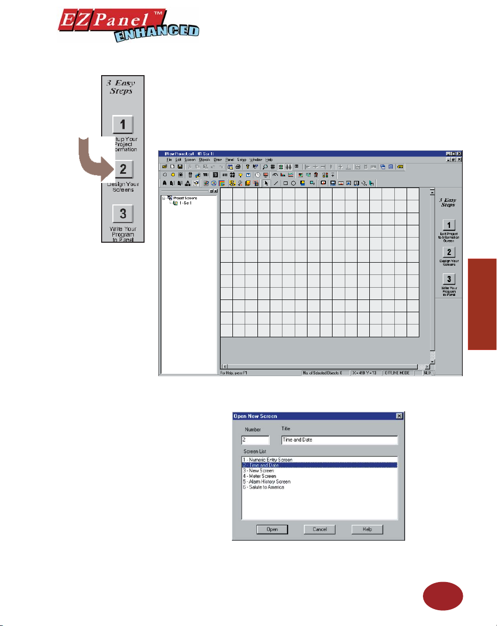
Step 2 Design Your Screens
Editor Programming Software User Manual
Your project information has been entered and you are now ready to begin
designing your screens. Remember that you can go back to step one and
change project information, if necessary. Just click on the 1 button on the
3 Easy Steps Tool Bar, shown to the left.
For more information on the Main Programming Screen, see page
136.
Project Setup
1. Click on the 2 button, Design Your Screens, and the following
2. Double click on one of the screens in the Screen List to open it,
screen will appear.
or enter a new screen number and name and click on the Open
button.
39
Page 52
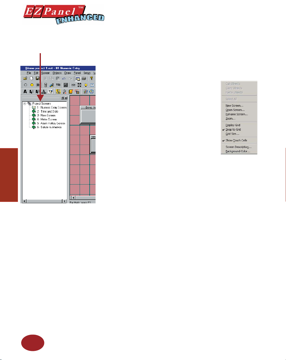
Editor Programming Software User Manual
Screens — Explorer View
Project Setup
3. You may also use the Screen Explorer view to navigate between
screens. Double click on an existing screen listed in the Explorer
window that you want to edit. The Main Programming Screen
will open to the selected screen. You can easily switch between
screens you are working on, to copy, paste, make changes,
etc.
4. Right click the mouse at any time while
designing your screens to access the menu
shown to the right
Some of the screen design features available
to you are:
• Program labels in up to 9 languages
• Popup Keypad that allows you to enter
data
• Vector-based graphics for easy sizing,
displayed in up to 128 colors
• Graphical trending
• PID loop tune face plates
• Recipe download
• Thumbwheel interface
• Radio buttons
• Analog clocks
• Meters, switches and lamps
• Symbol Factory® library of over 4,000 factory objects
5. You are now ready to begin confi guring objects.
40
Page 53
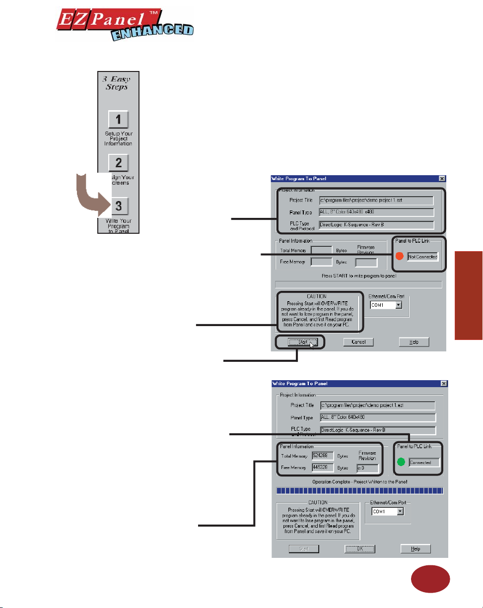
Editor Programming Software User Manual
Step 3 Write Your Program to Panel
Click on the button for Step 3, Write Your Program to Panel. Check to
ensure that “Ethernet/COM Port” matches the port that is connected to
your panel and click on the Start button. Read the information below to
learn more about the “ Write Program to Panel” screen.
Project Information: Provides
information about the current
project you are about to
transfer to the panel.
Panel to PLC Link will display “Not
Connected” until download is completed.
DON’T LOSE AN EXISTING PROGRAM! If
you’re not sure of the changes you have
made, save the existing program to a
different project name from the one you are
about to transfer to the panel before you
click on the Start button.
Before Panel Write....
Project Setup
Press the Start Button, the program will
be transferred to the panel.
If the panel is connected to a PLC, the
Panel to PLC Link will display a green
dot next to the “Connected” message to
indicate that a link is established.
Panel Information will display the
Total and Free Memory in Bytes. (Most
models allow you to increase memory
by adding another RAM card.) It will
also display the Firmware Revision
number — the revision of the EZPanel
Enhanced internal fi rmware.
Panel Write Completed....
41
Page 54
Editor Programming Software User Manual
EZPanel Enhanced is shipped with a bitmap program
installed. The image shown above will display on the
EZPanel Enhanced screen upon initial power-up. The
fi rst project you transfer to the panel will replace this
bitmap program!
Project Setup
42
Page 55

Objects
In this chapter you will be shown how to create....
— Buttons
— Indicator Buttons
— Radio Buttons
— Switches
— Step Switch
— Tri-state Switch
— Numeric Entry
— Recipe
— Thumbwheel
— Indicator Lights
— Numeric Display
— Text Objects
— Clock Object
— Meter
— Bar Graphs
— Line Graph
— PID Face Plate
— Change Screen
— Alarm History
— System Objects
— Multi-state Indicator
— Bitmap Objects
— Increment/Decrement Value
4
Page 56
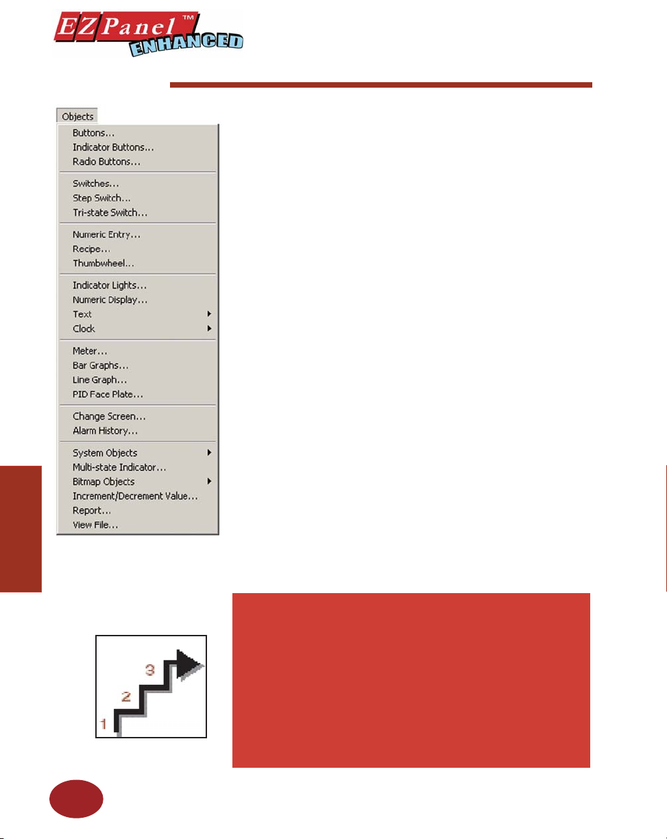
Objects Menu
Objects
Editor Programming Software User Manual
In PLC-based control, the PLC performs the following control sequence
continuously: reads inputs, solves control logic ( ladder logic), writes values,
and sets/resets outputs. The state of inputs and outputs is kept as bits in a
data table. The data table is typically organized in words, with each word
having 16 bits. Data values, such as parts count, are also kept as words
in the data table.
EZPanel Enhanced provides direct access to the bits and words of the
PLC data table, without going through I/O modules. The panel provides
this access through its tags. EZPanel Enhanced has tags that are mapped
to the PLC data table. The mapping between panel tags and PLC data
tables is user-defi ned through a simple dialog box. EZPanel Enhanced
objects allow you to set/reset bits and to read/write from the PLC data table
through the panel tags.
For example, when a panel button object is pressed, it sets a panel tag.
The panel transfers the state of this tag to the mapped bit in the PLC data
table. Similarly, the PLC may set an output bit that turns on a pilot light
on the panel.
Please Note: Panel Tags may be internal (not mapped to
the PLC) or external (mapped to the PLC).
Panel Tags may be:
• Discrete
• 16-bit ( Signed/Unsigned)
• 32-bit ( Signed/ Unsigned)
• 16-bit BCD
• 32-bit BCD
• 32-bit Floating Point
• ASCII String
44
IMPORTANT! To learn all the steps to confi guring an
object, read the instructions for the fi rst object, Button
Object, in its entirety. It will take you through each step in
detail, explaining all the variables and choices. Because
the objects share many common features, they are not
repeated for each object. Any features that are unique to
a particular object are explained in its own section. We
recommend that you try out the tutorial, beginning on
page 14, to learn the steps involved in creating an EZPanel
Enhanced project.
Page 57
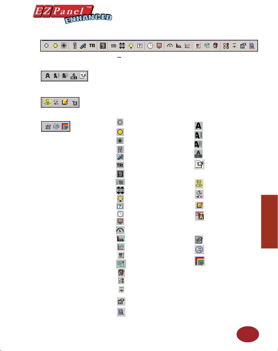
BASIC OBJECTS TOOL BAR
TEXT OBJECTS TOOL BAR
Editor Programming Software User Manual
The Objects menu allows you to choose from several predefi ned objects.
Objects provide generic panel functions. The objects can be accessed from
the Object Tool Bars — Basic Objects, Text Objects, System Objects,
and Bitmap Objects — shown above and to the left, and the Objects Menu
shown on the preceding page.
SYSTEM OBJECTS TOOL BAR
BITMAP OBJECTS TOOL BAR
Configure an object
by selecting it from the
OBJECT MENU or one
of the OBJECT TOOL
BARS
All of the objects in this menu have user-defi ned frame types, line and fi ll
colors, and text. To confi gure an object, click on the object icon on the
object tool bars or on the object name in the menu drop down list with your
mouse.
Basic Objects Tool Bar Icon
Text Objects Tool Bar Icon
• Buttons
• Indicator Buttons
• Radio Buttons
• Switches
• Step Switch
• Tri-State Switch
• Numeric Entry
• Static Text
• Triggered Text
• Lookup Text
• Dynamic Text
• Text Entry
System Objects Tool Bar Icon
• Recipe
• Thumbwheel
• Indicator Lights
• Numeric Display
• Analog Clock
• Adjust Contrast
Increment/Decrement
•
Hour
• Activate Screen Saver
• Select Language
• Digital Clock
• Meter
• Bar Graph
• Line Graph
• PID Face Place
Bitmap Objects Tool Bar Icon
• Dynamic Bitmap
• Bitmap Button
• Multi-state Bitmap
• Change Screen
• Alarm History
• Multi-state Indicator
• Increment/Decrement
Value
• Report
• View File
Objects
45
Page 58
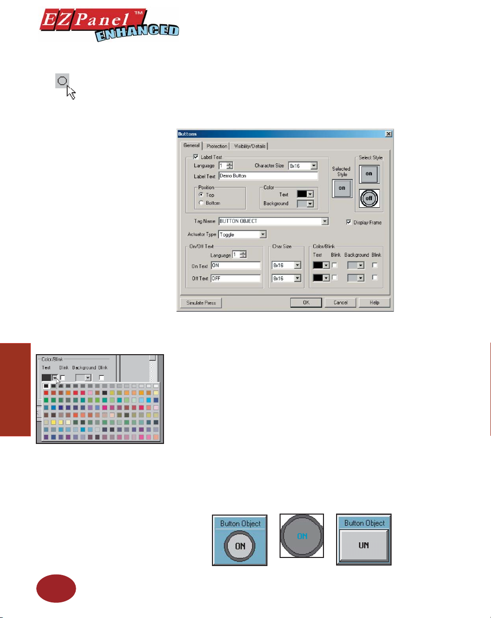
Button Object
Editor Programming Software User Manual
Pressing a Button object allows you to WRITE to a Tag. It can be displayed in a variety of colors, sizes and shapes and has a simulation option (allowing you to see how it will look when pressed). You may select
from 5 types of button states: Momentary ON, Momentary OFF, Set ON,
Set OFF and TOGGLE.
Choose from 128 Colors!
Objects
Click on the down arrow next to
the default color block for text or
background to view the color palette.
Move the cursor over your choice and
simply click to select.
46
To put a Label on a Button, perform the following steps:
1. Click on the box in front of Label Text.
2. Use the UP/DOWN arrows after the Language box to select a
language number. (See section on Language, page 180.)
3. Select Character Size from the available choices.
4. Enter Label Text up to 40 characters.
5. Select the Position of the label, whether you want it to appear
at the Top or the Bottom of the object frame.
6. Select the Tex t and Background Color. Click on the down arrow
to view the color palette.
7. Display Frame is selected by default. If you do not want the
frame around the button to be visible, click on the box to deselect
(the box will be empty).
To Choose a Button Style, perform the following steps:
1. Under Select Style, click on the style you prefer for the button
object you are creating.
2. Your choice will appear under Selected Style.
Page 59
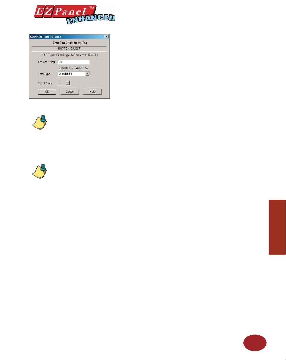
Editor Programming Software User Manual
Enter a Tag Name:
1. Enter a Tag Name or click on the down arrow and select the Tag
2. If the Tag Name is new, the Add New Tag Details dialog box will
Name that you want the button to correspond to.
appear where you will map the tag. The Tag Name will appear
in the fi rst fi eld. Enter an Address String appropriate for your
type PLC. Click on the OK button.
For more information about Tags, see
Tag Database, page 165.
NOTE: If your panel is
connected to multiple PLCs, use
the Station Number to address
a specifi c PLC. For example:
2–V2002 would address the
PLC Station Number 2.
NOTE: If you select Momentary
ON or Momentary OFF, the
PLC must set bit to proper
state on powerup. This must
be done when programming
PLC Logic.
Hello...
Hola...
Guten Tag...
For each object, you may
program the text to display in up
to 9 Languages! (See Language
section on page 180.)
NOTE: To edit the Address String, with your cursor in the
Tag Name fi eld, click on the right mouse button. The Edit
Tag Details screen will appear.
Select from the following Actuator Types:
Actuator Type determines how the tag will be controlled. NOTE: If
you have assigned Password Protection for this object and select
Momentary On or Momentary Off, the protection feature is disabled
with this actuator type.
• Momentary On will turn the tag on for as long as you touch
the button. (Password Protection is disabled.)
• Momentary Off will turn the tag off for as long as you touch
the button. (Password Protection is disabled.)
• Set On will latch the tag ON.
• Set Off will latch the tag OFF.
• Toggle will change the state of the tag every time the button is
pressed.
Enter On/Off Text:
Here you will enter the Text that will appear within the object, and control
how that text will appear.
1. Select the Language number (1–9) for the On/Off Text.
2. Type in what you want to appear within the button for the On
Tex t and for the Off Text (i.e., you might want to place the words
STOP and RUN inside the buttons, instead of Off and On).
3. Select Character Size from the available choices
4. Select the Color of the Text and the Color of the
Background.
5. If you want the Te xt or the Background to Blink, click on the
box below Blink to place a check mark indicating that the option
is enabled.
Objects
OK/Cancel/Help Buttons
• Click on OK button to save your selections and exit the dialog
• Click on Cancel button to exit the dialog box without saving
• Click on Help button to go to the Help Topic for that dialog box.
Place Button on the screen and size it.
• To size the button, grab a handle and drag it to the size you
box.
your selections.
want.
47
Page 60
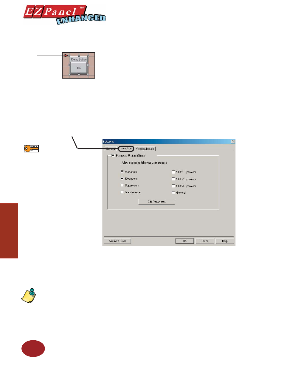
Editor Programming Software User Manual
Grab a handle with
your mouse
Click on the Protection Tab
The following touch objects allow
you to enable protection and assign
passwords to allow a group or
individual (user-defined) to have
access to that object:
Buttons
Indicator Buttons
Switches
Step Switches
Tri-State Switches
Numeric Entry
Recipe
Thumbwheel
Text Entry
Change Screen
Objects
Alarm History
Increment/Decrement Hour
Activate Screen Saver
Adjust Contrast
Select Language
Bitmap Button
Increment/Decrement Value
• To move the button, select it, click and hold left mouse button
and drag it to the area of the screen where you want it to
appear.
Simulate Press
To Simulate Press, double click the object to bring up the object dialog
box. (You may have to drag the dialog box to see the object on the
programming screen.) Click on the Simulate Press button to see how the
button object will display on the screen when pressed.
Protection Tab
The Password Protect Object feature allows you to prevent unauthor-
ized users from accessing certain objects and their functions. This
feature is useful when several people will be using EZPanel Enhanced
to perform different tasks, such as, changing initial values, or monitoring
system status. To enable password protection for the object, click in the
box in front of the groups you wish to allow access.
IMPORTANT!
Password Protection is not
intended to work with objects
when the actuator type
selected is Momentary On and
Momentary Off.
48
Edit Passwords
There are eight groups that you may assign Passwords to. Passwords
allow you to implement restrictions on who can use the password protected objects (e.g., to make system or internal panel adjustments, enter
text or values, or control a machine function in your application). Click
on the Edit Passwords button to setup or change the passwords.
GROUP
Page 61
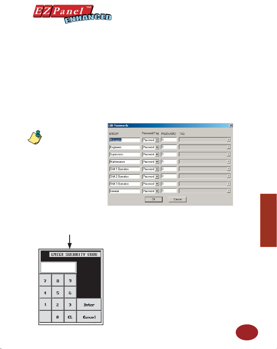
NOTE: If you enter a password
with leading zeroes, e.g., 00003
or 00533, the leading zeroes will
be ignored!
Editor Programming Software User Manual
(You may change the Group names to suit your application.)
✔ Managers
✔ Engineers
✔ Supervisors
✔ Maintenance
✔ Shift 1 Operator
✔ Shift 2 Operator
✔ Shift 3 Operator
✔ General
Password/Tag
A keypad similar to the one
shown below will appear on the
panel when a protected objected
is pressed, prompting the operator
to enter the password.
Select whether or not you want your password to be stored in the panel or
Objects
in the PLC. If you choose Password, it will be stored in the panel. If you
choose Tag, it will be stored in the PLC.
PASSWORD
A 1–10 digit number (numeric only) is assigned here. The user must then
enter this number to perform protected functions for a particular Group.
You will not be allowed to enter a password if you select Tag in the second
column.
Do not enter leading zeroes in a password. Leading zeroes are ignored.
In other words, if you enter a password of 00456, your password will
be 456.
TAG
Tag names are assigned to PLC addresses that hold the passwords. This
allows you to store the codes in your PLC. You will not be allowed to enter
a Tag if you select Password in the second column.
49
Page 62
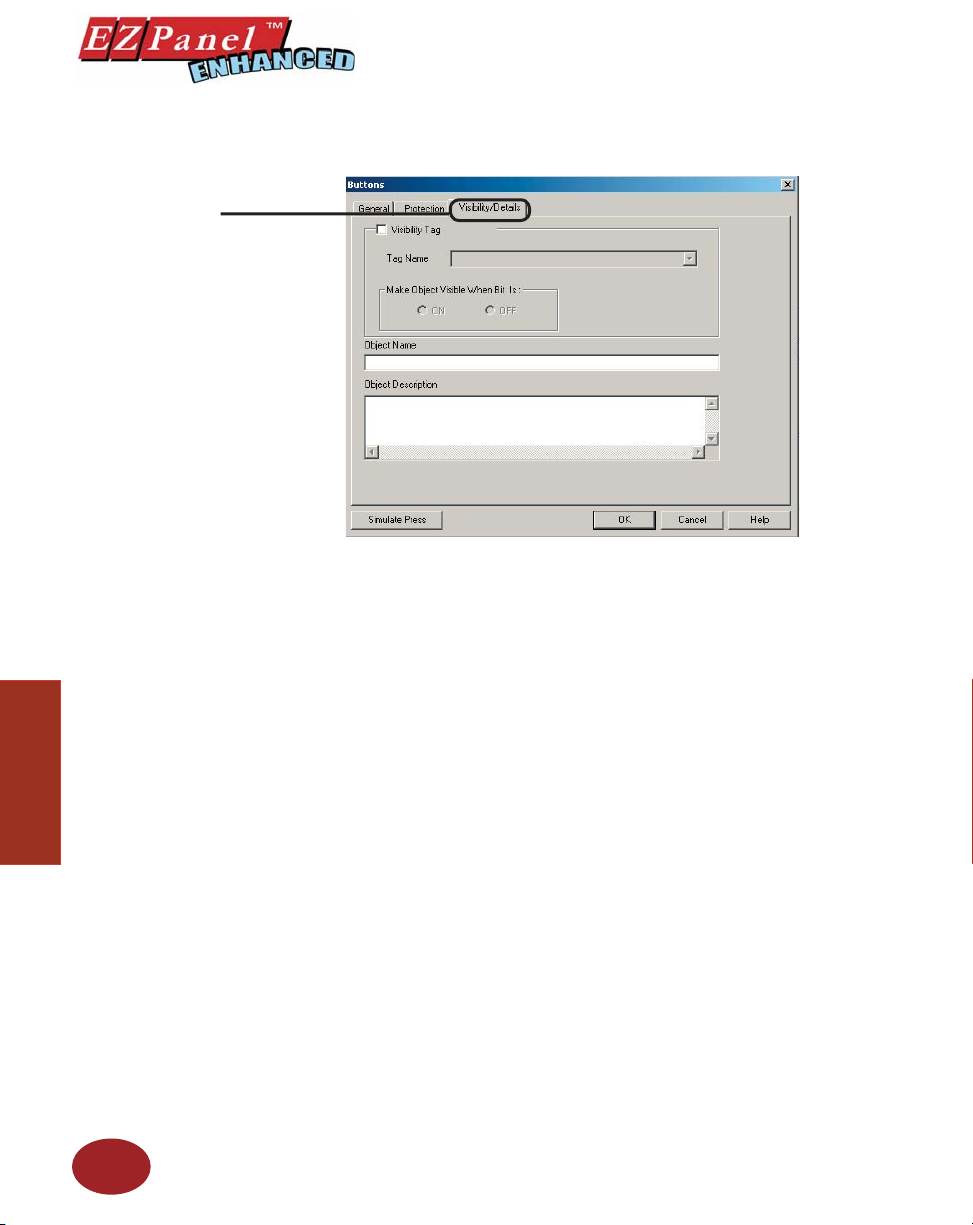
Click on the Visibility/Details
Editor Programming Software User Manual
Visibility/Details Tab
Visibility
Objects
1. Check the box in front of Visibility Tag if you want to control
when the object is visible on the screen. (If it is not checked the
object will always be visible.)
2. Click on the down arrow next to the Tag Name box to view a list
of the tags you have previously programmed or create a new
one. Select the tag that links the object to the register bit that
you want to control it.
3. Select whether you want the Object Visible when the bit is ON
or OFF.
Details
1. Type in a name for the object in the space provided under Object
Name. The name can be up to 40 characters long.
2. Type in a description of the object in the space provided under
Object Description. An Object Description can be up to 400
characters long.
50
Page 63
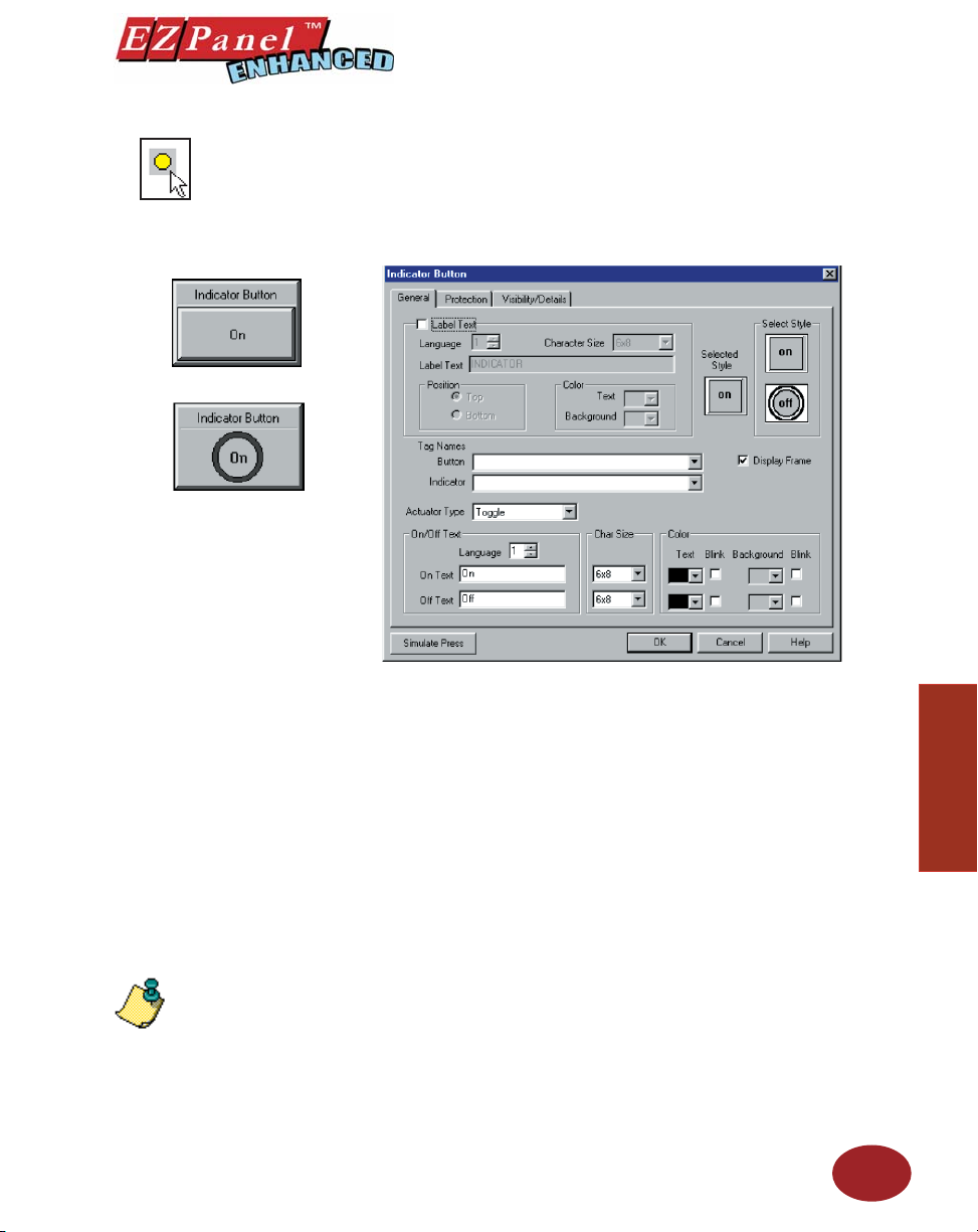
Indicator Button Object
Editor Programming Software User Manual
An Indicator Button combines a regular button with an i ndicator light. It
allows you to perform a WRITE operation to one bit and a READ operation from a second discrete location. The state of that READ location
determines whether the button is displayed in the ON or OFF mode. You
may choose to make the READ and WRITE location the same.
To put a Label on an Indicator Button, perform the following steps:
NOTE: To edit the Address
String, with your cursor in
the Tag Name fi eld, click on
the right mouse button. The
Edit Tag Details screen will
appear.
1. Click on the box in front of Label Text.
2. Use the UP/DOWN arrows after the Language box to select a
language number. (See section on Language, page 180.)
3. Select Character Size from the available choices.
4. Enter Label Text up to 40 characters.
5. Select the Position of the label, whether you want it to appear
at the Top or the Bottom of the object frame.
6. Select the Text and Background Color. Click on the down arrow
to view the color palette.
7. Display Frame is selected by default. If you do not want the
frame around the button to be visible, click on the box to deselect
(the box will be empty).
To Choose an Indicator Button Style, perform the following steps:
1. Under Select Style, click on the style you prefer for the button
object you are creating.
2. Your choice will appear under Selected Style.
Enter a Tag Name:
1. Enter a Tag Name or click on the down arrow and select the
Tag Name that you want the Indicator button and the Indicator to
correspond to.
2. If the Tag Name is new, the Add New Tag Details dialog box
will appear where you will enter tag details. The Tag Name will
51
Objects
Page 64

NOTE: If you have assigned
Password Protection for this
object and select Momentary On
or Momentary Off, the protection
feature will not be enabled.
Also, if you select Momentary
ON or Momentary OFF, the
PLC must set bit to proper state
on powerup. This must be done
when programming PLC Logic.
Editor Programming Software User Manual
appear in the fi rst fi eld. Enter an Address String appropriate for
your type PLC. Click on the OK button.
Select from the following Actuator Types: Actuator Type determines
how the tag will be controlled.
• Momentary On will turn the tag on for as long as you touch
the button. (Password Protection is disabled.)
• Momentary Off will turn the tag off for as long as you touch
the button. (Password Protection is disabled.)
• Set On will latch the tag ON.
• Set Off will latch the tag OFF.
• Toggle will change the state of the tag every time the button
is pressed.
Enter On/Off Text: Here you will enter the Text that will appear within the
object, and control how that text will appear.
1. Select the Language number (1–9) for the On/Off Text.
2. Type in what you want to appear within the button for the On Text
and for the Off Text (i.e., you might want to place the words STOP
and RUN inside the buttons, instead of Off and On).
3. Select Character Size from the available choices
4. Select the Color of the Text and the Color of the Background.
5. If you want the Text or the Background to Blink, click on the
box below Blink to place a check mark indicating that the option
is enabled.
Objects
52
Protection (See Button Object.)
Visibility/Details (See Button Object.)
OK/Cancel/Help Buttons
• Click on OK button to save your selections and exit the dialog
box.
• Click on Cancel button to exit the dialog box without saving
your selections.
• Click on Help button to go to the Help Topic for that dialog box.
Place Indicator Button on the screen and size it.
• To size the Indicator button, select it, grab a handle and drag.
• To move the button, select it, click and hold left mouse button
and drag it to where you want it to appear on the screen.
Simulate Press
To Simulate Press, double click the object to bring up the object dialog
box. (You may have to drag the dialog box to one side to see the object
on the programming screen.) Click on the Simulate Press button to see
how the button object will display on the screen when pressed.
Page 65
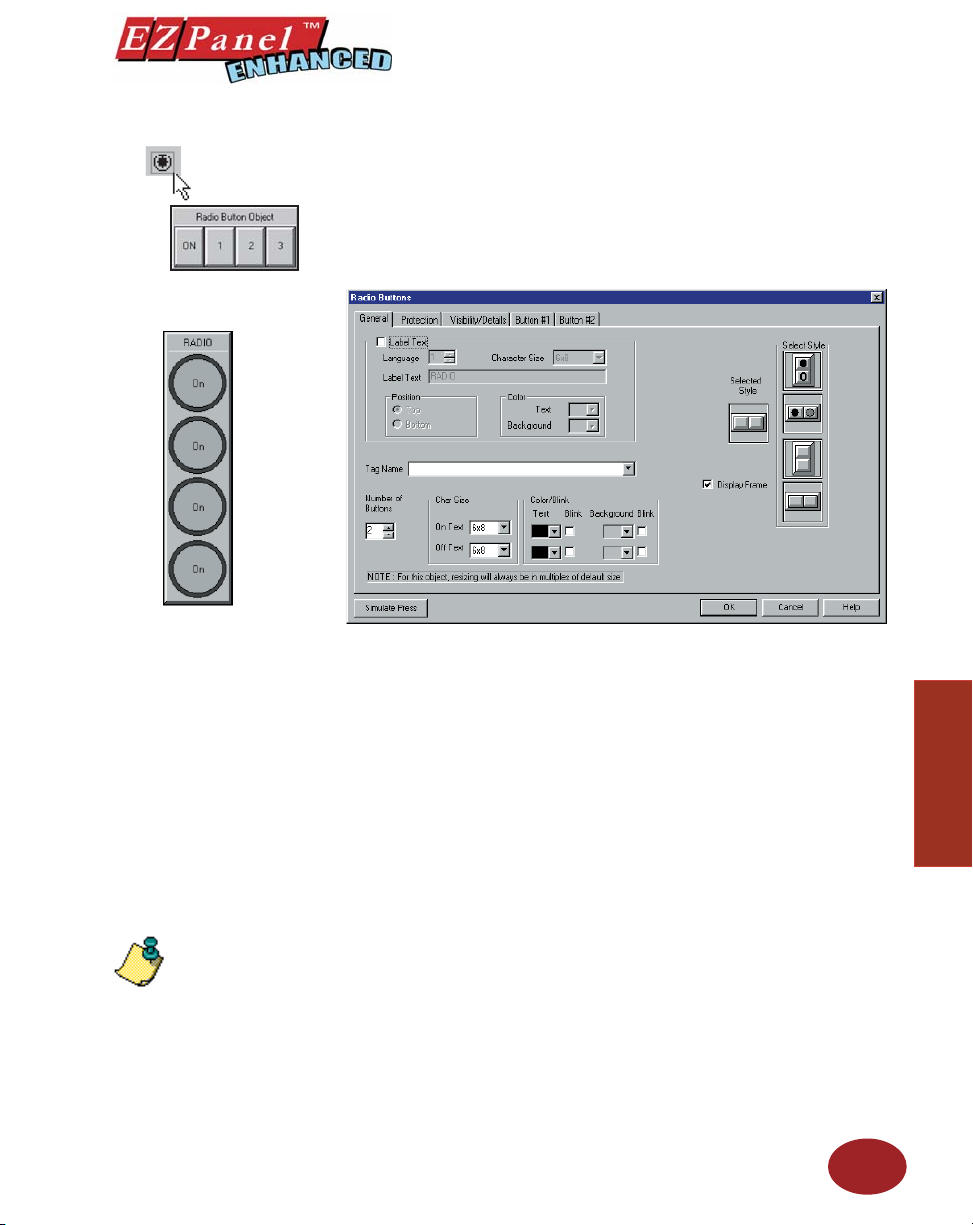
Radio Buttons Object
Editor Programming Software User Manual
The Radio Button object has a maximum of 8 buttons, however, only
one can be on at any given time. When a button is pressed it releases
any button that may be ON, and becomes the active button. Each button
controls a bit and is assigned an area of the touchscreen. Radio buttons
can have from 2 to 8 buttons. Please note that no more than 6 vertical
buttons can be used for the regular 6-inch panels, slim bezels with 192
(16 x 12) touch cells can have up to 8 buttons.
NOTE: To edit the Address
String, with your cursor in
the Tag Name fi eld, click on
the right mouse button. The
EDIT TAG DETAILS screen
will appear.
To put a Label on a Radio Button, perform the following steps:
1. Click on the box in front of Label Text.
2. Use the UP/DOWN arrows after the Language box to select a
language number. (See section on Language, page 180.)
3. Select Character Size from the available choices.
4. Enter Label Text up to 40 characters.
5. Select the Position of the label, whether you want it to appear
at the Top or the Bottom of the object frame.
6. Select the Tex t and Background Color. Click on the down arrow
to view the color palette.
7. Display Frame is selected by default. If you do not want the
frame around the button to be visible, click on the box to deselect
(the box will be empty).
To Choose a Radio Button Style, perform the following steps:
1. Under Select Style, click on the style you prefer for the button
object you are creating.
2. Your choice will appear under Selected Style.
Enter a Tag Name:
1. Enter a Tag Name or click on the down arrow and select the Tag
Name that you want to button to correspond to.
2. If the Tag Name is new, the Add New Tag Details dialog box
will appear where you will enter tag details. The Tag Name will
appear in the fi rst fi eld. Enter an Address String appropriate
53
Objects
Page 66
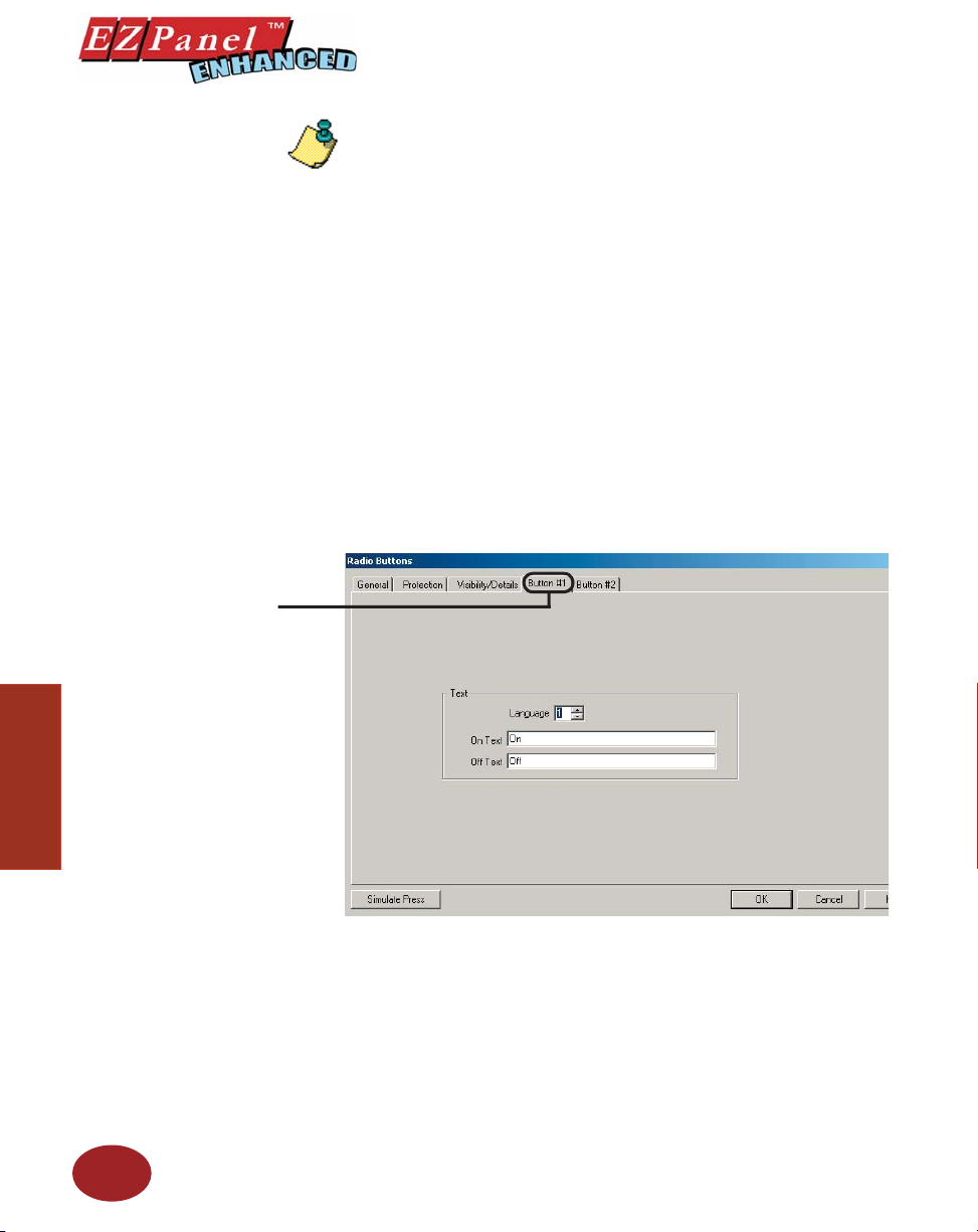
Editor Programming Software User Manual
Click on the Button #1 Tab
to edit Language and On/Off
Text.
NOTE: This object can use a signed or unsigned Data Type. Button 1 = Bit 0
for your type PLC. Click on the OK button.
in assigned tag. Button 8 = Bit 7 in assigned tag. Bits 9 to 15 are not used.
Select Number of Buttons:
1. Click on the UP or DOWN arrow to select the number of radio
buttons. You may choose from 2 to 8 buttons. (You may only
have 6 buttons for 6-inch panels with 48 touch cells.)
Enter On/Off Text:
Text size and color are programmed under the General Tab. These
characteristics will be implemented for all of the inside button text.
1. Select the Character Size for the On Text and the Off Text.
2. Choose the Color of the Text by clicking on the arrow button to
view the color palette. Move the cursor over the color you want
and click to select.
3. Select whether or not the Text will Blink.
4. Next, select the Background Color of the button and whether
or not it will Blink.
5. Each Radio Button (from 2 to 8) may contain different text and
Objects
54
6. Choose the Language number (1–9) and type in the text as you
a different language. Click on the Button #1 tab.
want it to appear within that button when ON and when OFF (i.e.,
you might want to place the words STOP and RUN inside the
buttons, instead of Off and On).
Remember that the other universal characteristics for the
button text and background have been chosen under the
Page 67

Editor Programming Software User Manual
Protection (See Button Object.)
General Tab (character size, color, etc.).
Visibility/Details (See Button Object.)
OK/Cancel/Help Buttons
• Click on OK button to save your selections and exit the dialog
box.
• Click on Cancel button to exit the dialog box without saving
your selections.
• Click on Help button to go to the Help Topic for that dialog box.
Place Radio Button on the screen and size it.
• To size the button, select it, grab a handle and drag.
• To move the button, select it, click and hold left mouse button
and drag to where you want it to appear on the screen.
Simulate Press
To Simulate Press, double click the object to bring up the object dialog
box. (You may have to drag the dialog box to see the object on the
programming screen.) Select the tab of the button you want to simulate.
Click on the Simulate Press button to see how the button object will display on the screen when pressed.
Objects
55
Page 68
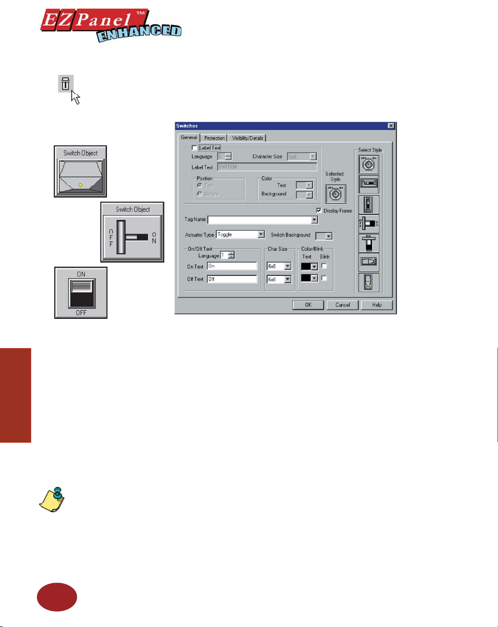
Editor Programming Software User Manual
Switch Object
Objects
There are several types of Switch objects that you may place on the
EZPanel Enhanced screen. They simulate mechanical switches of the
same type, e.g.; Throw Switch, Selector Switch, Slide Switch, Toggle
Switch, etc.
To put a Label on a Switch, perform the following steps:
1. Click on the box in front of Label Text.
2. Use the UP/DOWN arrows after the Language box to select a
language number. (See section on Language, page 180.)
3. Select Character Size from the available choices.
4. Enter Label Text up to 40 characters.
5. Select the Position of the label, whether you want it to appear
at the Top or the Bottom of the object frame.
6. Select the Tex t and Background Color. Click on the down
arrow to view the color palette.
7. Display Frame is selected by default. If you do not want the
frame around the switch to be visible, click on the box to deselect
(the box will be empty).
NOTE: To edit the Address
String, with your cursor in
the Tag Name fi eld, click on
the right mouse button. The
EDIT TAG DETAILS screen
will appear.
56
To Choose a Switch Style, perform the following steps:
1. Under Select Style, click on the style you prefer for the switch
object you are creating.
2. Your choice will appear under Selected Style.
Enter a Tag Name:
1. Enter a Tag Name or click on the down arrow and select the Tag
Name that you want the switch to correspond to.
2. If the Tag Name is new, the Add New Tag Details dialog box
will appear where you will enter tag details. The Tag Name will
appear in the fi rst fi eld. Enter an Address String appropriate
for your type PLC .Click on the OK button.
Page 69

NOTE: If you select Momentary
ON or Momentary OFF, the
PLC must set bit to proper
state on powerup. This must
be done when programming
PLC Logic.
Editor Programming Software User Manual
Select the Switch Background color by clicking on the DOWN arrow and
selecting a color from the palette.
Select from the following Actuator Types:
Actuator Type determines how the tag will be controlled. If you have
assigned Password Protection for this object and select Momentary
On or Momentary Off, the protection feature will not be enabled with
this actuator type.
• Momentary On will turn the tag on for as long as you touch the
switch. (Password Protection is disabled.)
• Momentary Off will turn the tag off for as long as you touch the
switch. (Password Protection is disabled.)
• Set On will latch the tag ON.
• Set Off will latch the tag OFF.
• Toggle will change the state of the tag every time the switch is
pressed.
Enter On/Off Text:
Here you will enter the Text that will appear within the object, and control
how that text will appear.
1. Select the Language number (1–9) for the On/Off Text.
2. Type in what you want to appear within the switch for the On Text
and for the Off Text (i.e., you might want to place the words STOP
and RUN inside the switches, instead of Off and On).
3. Select Character Size from the available choices
4. Select the Color of the On Text and the Color of the Off Text.
5. If you want the Text to Blink, click on the box below Blink to
place a check mark indicating that the option is enabled.
Protection (See Button Object.)
Visibility/Details (See Button Object.)
OK/Cancel/Help Buttons
• Click on OK button to save your selections and exit the dialog
box.
• Click on Cancel button to exit the dialog box without saving
your selections.
• Click on Help button to go to the Help Topic for that dialog box.
Place Switch on the screen and size it.
• To size a switch, click on it to select, grab a handle with the
mouse and drag to the size you want.
• To move the switch, select it, click and hold left mouse button,
and drag to where you want it to appear on the screen.
57
Objects
Page 70
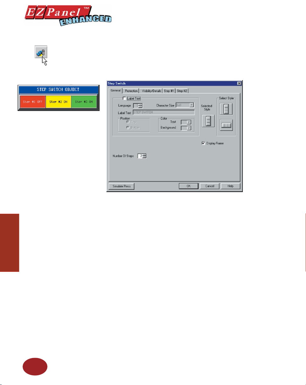
Step Switch Object
Editor Programming Software User Manual
The Step Switch object simulates a Mechanical Step Switch on the panel. It
allows you to simultaneously monitor and control two, three, or four different
bits and display ON and OFF text for each bit. Each time the Step Switch
is pressed, each bit will be cycled one at a time from OFF to ON with only
one bit ON at a time.
Objects
58
To put a Label on a Switch, perform the following steps:
1. Click on the box in front of Label Text.
2. Use the UP/DOWN arrows after the Language box to select a
language number. (See section on Language, page 180.)
3. Select Character Size from the available choices.
4. Enter Label Text up to 40 characters.
5. Select the Position of the label, whether you want it to appear
at the Top or the Bottom of the object frame.
6. Select the Text and Background Color. Click on the down arrow
to view the color palette.
7. Display Frame is selected by default. If you do not want the
frame around the switch to be visible, click on the box to deselect
(the box will be empty).
To Choose a Step Switch Style, perform the following steps:
1. Under Select Style, click on the style you prefer for the button
object you are creating.
2. Your choice will appear under Selected Style.
Choose the Number of Steps (from 1 to 4) in the process or application
that you want your switch to control. Enter the number of steps or click on
the up/down arrows to select.
Page 71
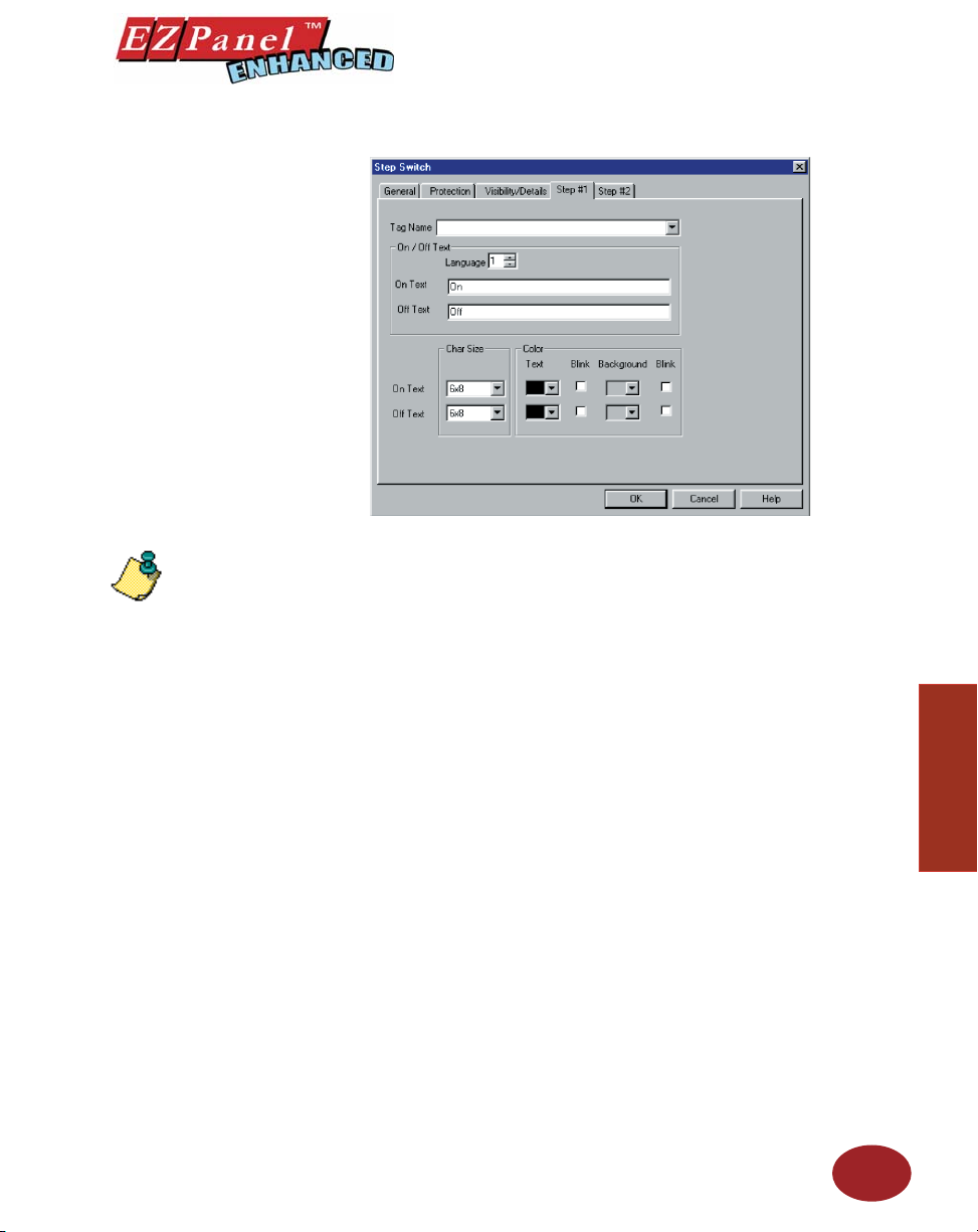
NOTE: To edit the Address
String, with your cursor in
the Tag Name fi eld, click on
the right mouse button. The
EDIT TAG DETAILS screen
will appear.
Editor Programming Software User Manual
Step #1 Tab
1. Click on Step #1 tab.
2. Enter Tag Name for Step #1.
3. Select Language (1 to 9) for On/Off Text and then enter the On
Tex t and Off Text that you want to appear within Step Switch
#1.
4. Select Character Size, Color of Tex t and Background and
whether or not, Text and/or Background will Blink.
5. Repeat for Step #2, Step #3 and Step #4, if necessary.
Protection (See Button Object.)
Visibility/Details (See Button Object.)
OK/Cancel/Help Buttons
• Click on OK button to save your selections and exit the dialog
box.
• Click on Cancel button to exit the dialog box without saving
your selections.
• Click on Help button to go to the Help Topic for that dialog box.
Place Step Switch on the screen and size it.
• To size the switch, grab a handle and drag.
• To move the switch, select it, click and hold left mouse button
and drag.
Simulate Press
To Simulate Press, double click the object to bring up the object dialog
box. (You may have to drag the dialog box to see the object on the programming screen.) Select the tab of the Step you want to simulate (if on
General tab, will simulate Step 1 only). Click on the Simulate Press button to see how the switch object will display on the screen when pressed.
59
Objects
Page 72
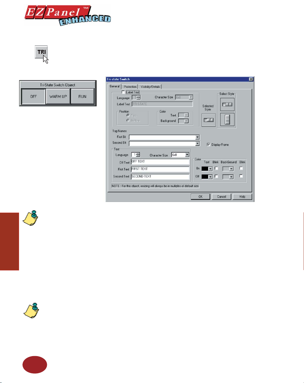
Tri-State Switch Object
Editor Programming Software User Manual
The Tri-State Switch object controls two bits at a time from two different
tags. It consists of three buttons. If the fi rst button is pressed, both the bits
are OFF. If the second button is pressed, the fi rst bit is ON and second bit is
OFF. If third button is pressed, the fi rst bit is OFF and second bit is ON.
To put a Label on a Switch, perform the following steps:
Objects
60
NOTE: The Tri-State switch
object is always snapped to
a touch cell to ensure that it
operates properly on the panel
screen. If you select the vertical
style, you will notice that a label
is not available (grayed out).
NOTE: To edit the Address
String, with your cursor in
the Tag Name fi eld, click on
the right mouse button. The
EDIT TAG DETAILS screen
will appear.
1. Click on the box in front of Label Text.
2. Use the UP/DOWN arrows after the Language box to select a
language number. (See section on Language, page 180.)
3. Select Character Size from the available choices.
4. Enter Label Text up to 40 characters.
5. Select the Position of the label, whether you want it to appear
at the Top or the Bottom of the object frame.
6. Select the Tex t and Background Color. Click on the down arrow
to view the color palette.
7. Display Frame is selected by default. If you do not want the
frame around the switch to be visible, click on the box to deselect
(the box will be empty).
To Choose a Tri-State Switch Style, perform the following steps:
1. Under Select Style, click on the style you prefer for the button
object you are creating.
2. Your choice will appear under Selected Style.
Tag Names
Click on the down arrow to select or enter new Tag Names for the First
Bit and for the Second Bit. If the Tag Name is new, the Add New Tag
Details dialog box will appear where you will enter tag details. The Tag
Name will appear in the fi rst fi eld. Enter an Address String appropriate
for your type PLC. Click on the OK button.
Page 73
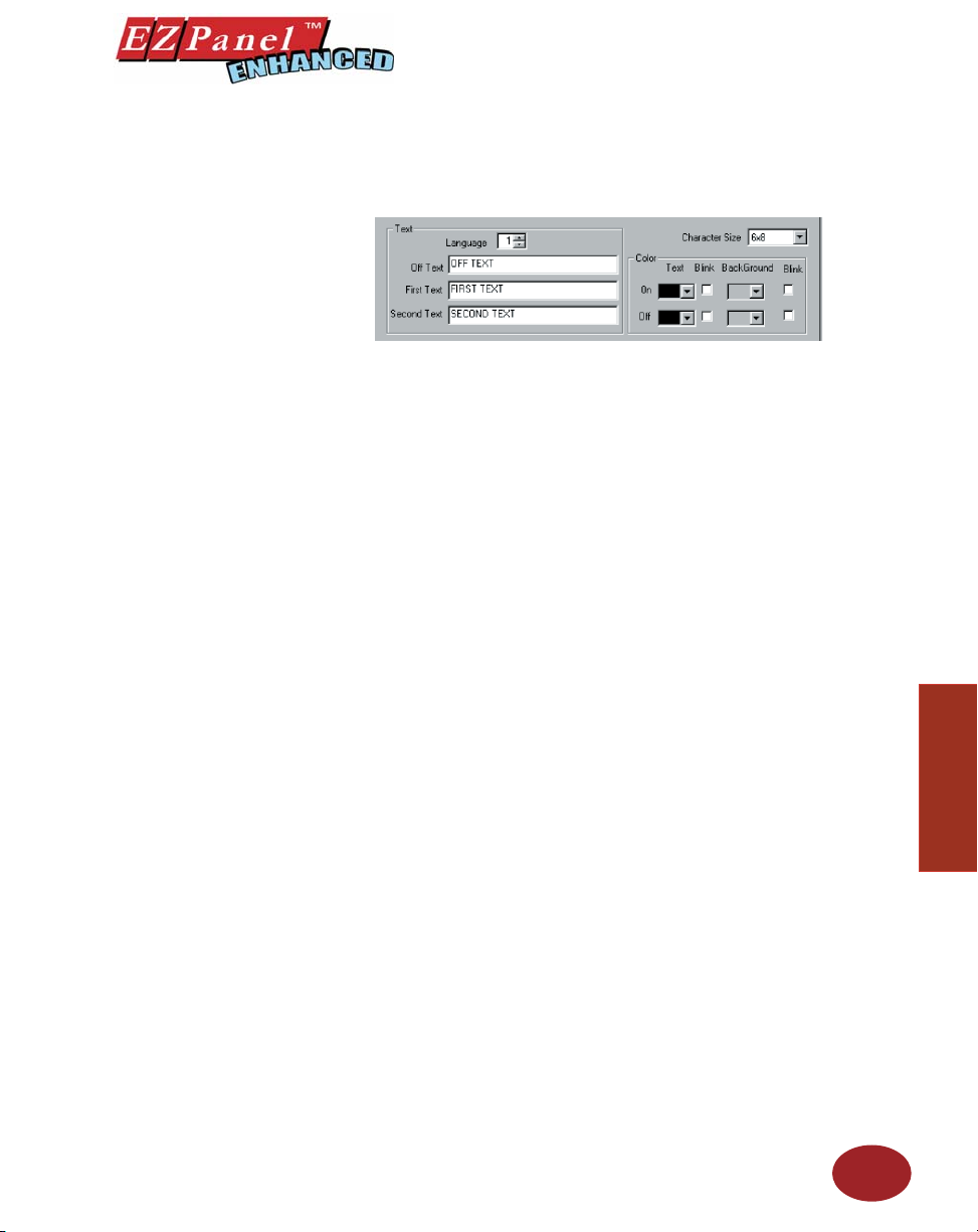
Editor Programming Software User Manual
Tex t
Here you will enter the Text that will appear within the object, and control
how that text will appear.
1. Select the Language number for the Off, First (bit) and Second
(bit) Text.
2. Type in what you want to appear within the button for the Off Text,
First Text and for the Second Text.
3. Select Character Size from the available choices.
4. Select the Color of the Text and the Color of the Background.
If you want the Text or the Background to Blink, click on the box
below Blink to place a check mark indicating that the option is
enabled.
Protection (see Button Object.)
Visibility/Details (see Button Object.)
OK/Cancel/Help Buttons
• Click on OK button to save your selections and exit the dialog
box.
• Click on Cancel button to exit the dialog box without saving
your selections.
• Click on Help button to go to the Help Topic for that dialog box.
Place Tri-State Switch on the screen and size it.
• To size the switch, grab a handle and drag it to size you want.
• To move the switch, select it, click and hold left mouse button
and drag to where you want it to appear on the screen.
Objects
61
Page 74
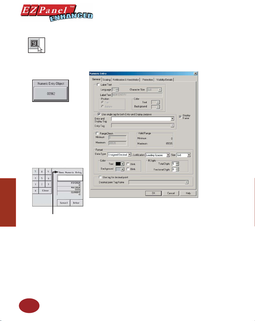
Numeric Entry Object
Editor Programming Software User Manual
The Numeric Entry object allows you to write a value to a PLC register. A
numeric keypad will pop up when the Numeric Entry object is pressed on
the EZPanel Enhanced screen. When you select a Tag Name, you will be
selecting the PLC location where you want the keypad accumulator data
to go. In other words, the value the operator enters on the keypad will be
written to the PLC location.
Objects
62
Please Note: Numeric
label is truncated to 20
characters on the popup
keypad.
To put a Label on the Numeric Entry object, perform the following
steps:
1. Click on the box in front of Label Text.
2. Use the UP/DOWN arrows after the Language box to select a
language number. (See section on Language, page 180.)
3. Select Character Size from the available choices.
4. Enter Label Text up to 40 characters.
5. Select the Position of the label, whether you want it to appear
at the Top or the Bottom of the object frame.
6. Select the Tex t and Background Color. Click on the down arrow
to view the color palette.
7. Display Frame is selected by default. If you do not want the
frame around the object to be visible, click on the box to deselect
(the box will be empty).
Choose Tag(s):
1. Choose whether or not you want to use a single tag for both Entry
and Display purposes, or two tags — a Display Tag and an Entry
Tag . Two tags will be necessary if you are using Expressions in
the tag. (See Note in margin on next page.)
Page 75
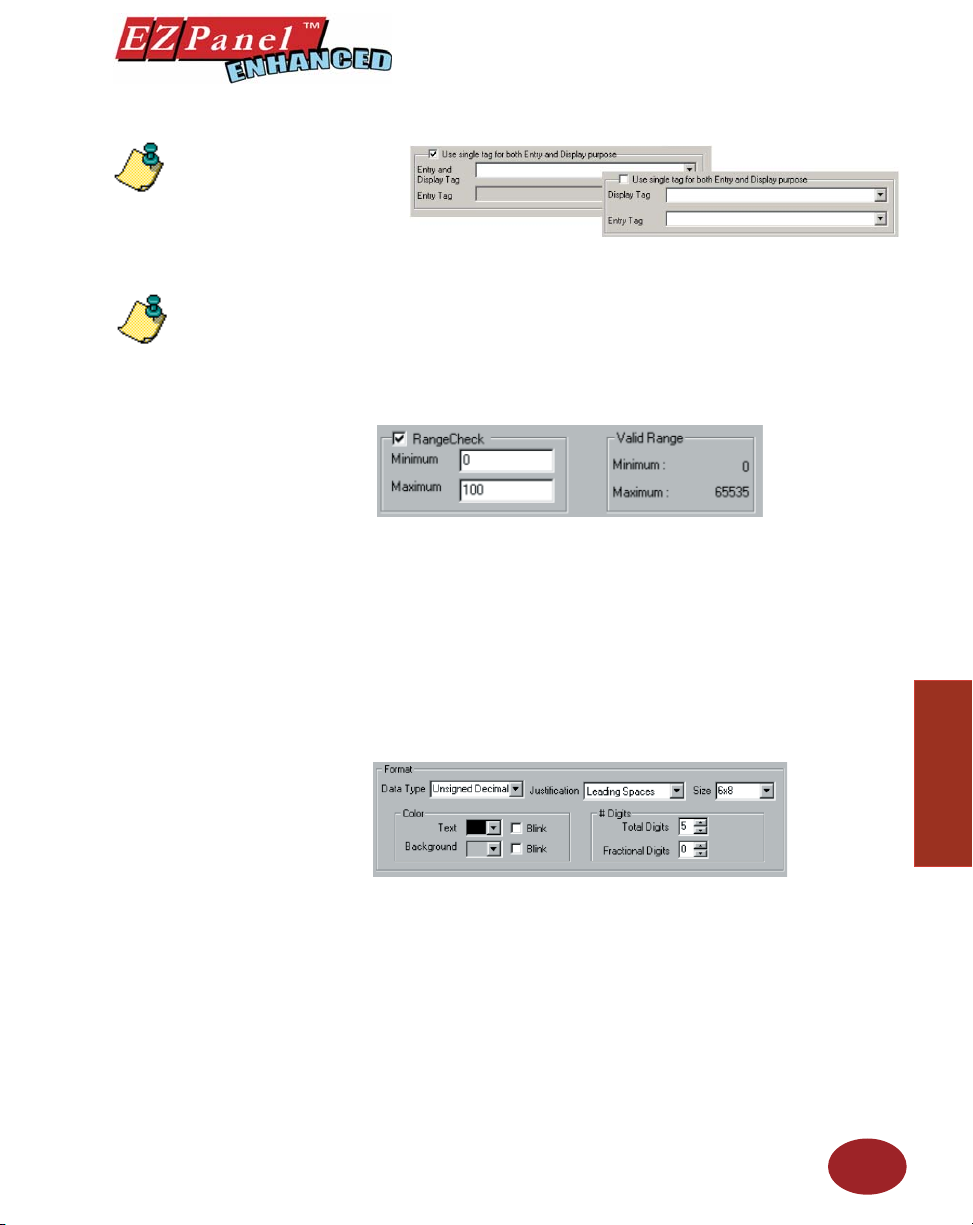
NOTE: To edit the Address
String, with your cursor in
the Tag Name fi eld, click on
the right mouse button. The
EDIT TAG DETAILS screen
will appear.
NOTE: When a single tag is
used, the I/O type the tag can
accept is Read/Write. When
two tags are used, the first
tag’s I/O type also accepts
Read Only and, therefore, can
defi ne source expressions.
Editor Programming Software User Manual
2. Enter a Tag Name or click on the down arrow and select the Tag
Name that you want the object to correspond to.
3. If the Tag Name is new, the Tag Entry dialog box will appear
where you will enter tag details. The Tag Name will appear in
the fi rst fi eld. Enter an Address String appropriate for your type
PLC and select the Data Type (from available choices). Click on
the OK button.
To Enter Range Check , perform the following steps:
1. Under Range Check, set the minimum and maximum set points.
2. Click on Maximum, the high end point, and enter a value. The
3. The Valid Range is shown. Your minimum and maximum set
To Select the Format of the Numeric Entry Keypad, perform the
following steps:
The Data Type is dependent upon the Tag data type. In turn, the Tag
data type is dependent upon the type of PLC you are using. Therefore,
your selections next to Data Type in this object will be limited by your Tag
and PLC data type. EZPanel Enhanced Editor Programming Software
will automatically limit your selections based on the PLC and Tag address
format. The program will also let you know if you have entered an invalid
data type.
SIGNED DATA TAG: SIGNED Keypad only
UNSIGNED DATA TAG: UNSIGNED, OCTAL, HEX Keypad
BCD DATA TAG: BCD Keypad only
FLOATING POINT TAG
(if available for that PLC): FLOATING POINT Keypad only
Click on Minimum, the low end point, and enter a value. The
operator will not be allowed to enter a value lower than the value
in this fi eld.
operator will not be allowed to enter a value higher than the value
in this fi eld. (Valid Range is shown in the next window.)
points must be within these limits.
63
Objects
Page 76
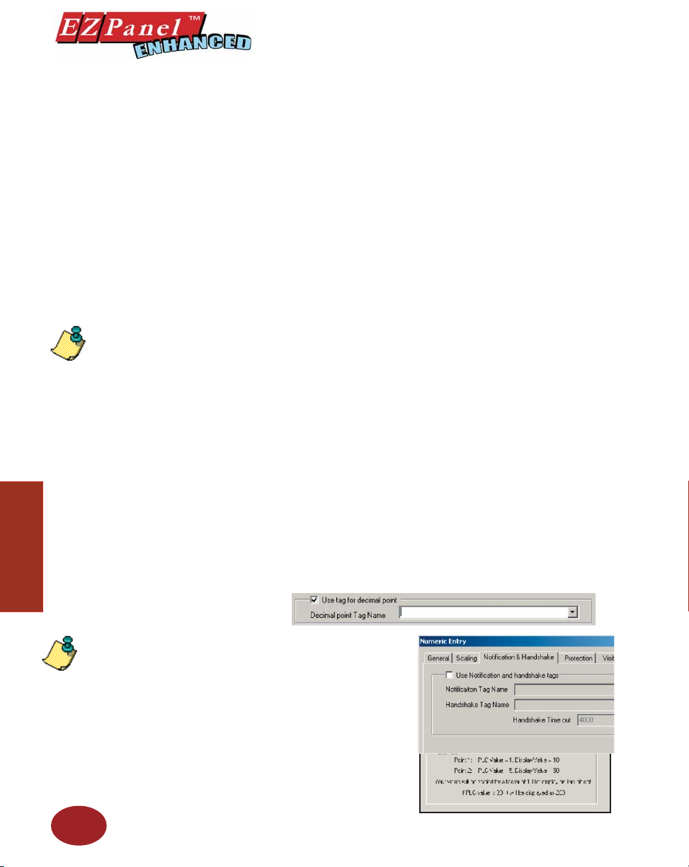
Objects
NOTE: If a Decimal Point
tag is selected, the Fractional
Digits will not be used. The
number of fractional digits
will come from the value of
the tag.
Editor Programming Software User Manual
The Data Types, and their respective ranges, that may be available, are
as follows:
Signed 16 Decimal: -32768 to +32767
Signed 32 Decimal: -2147483648 to +2147483647
Unsigned 16 Decimal: 0 to 65535
Unsigned 32 Decimal: 0 to 4294967295
Octal 16: 0 to 177777
Octal 32: 0 to 37777777777
Hex 16: 0 to FFFF
Hex 32: 0 to FFFFFFFF
BCD 16: 0 to 9999
BCD 32: 0 to 99999999
1. Click on Data Type and select from the available choices.
2. Click on Justifi cation and select from the following: Leading
Zeroes, Leading Spaces, or Trailing Spaces.
3. Click on Size and select from the available character sizes. (Click
on down arrow to view list of sizes.)
4. Under Color, click on down arrow to view the color palette for
Tex t. Click on any color to select.
5. Click on the box in front of Blink if you want your text characters
to blink.
6. Select color for Background and whether or not you want it to
Blink.
7. Click on Total Digits under # Digits. The panel will display
the minimum value and the maximum number inside the keypad.
Here you will select how many digits, from 1 to 10 (depending
on the data type and tag value type chosen), that you want to
display.
8. If you want Fractional Digits, enter 1 through 10 here (select 0
for none). For example, if your maximum value is 999, you would
enter 3 under total digits. If your maximum value is 99.9, enter 3
under Total Digits and 1 under Fractional Digits.
9. If you want a tag to control the decimal points, click in the box
in front of Use tag for decimal point and then enter or select a
Decimal point Tag Name.
NOTE: Click on the Scaling
tab if you want the Display
Value to be different than the
PLC Value.
64
Scaling Tab
Under the Numeric Entry object
Scaling tab, you can scale the
entered value from the numeric
entry object to another value in
the PLC. Enter the Point 1 and
Point 2 PLC Values and Point 1
and Point 2 Display Values.
(An example of SCALING is
provided on the dialog box.).
Notification and Handshake
Tab :
Page 77
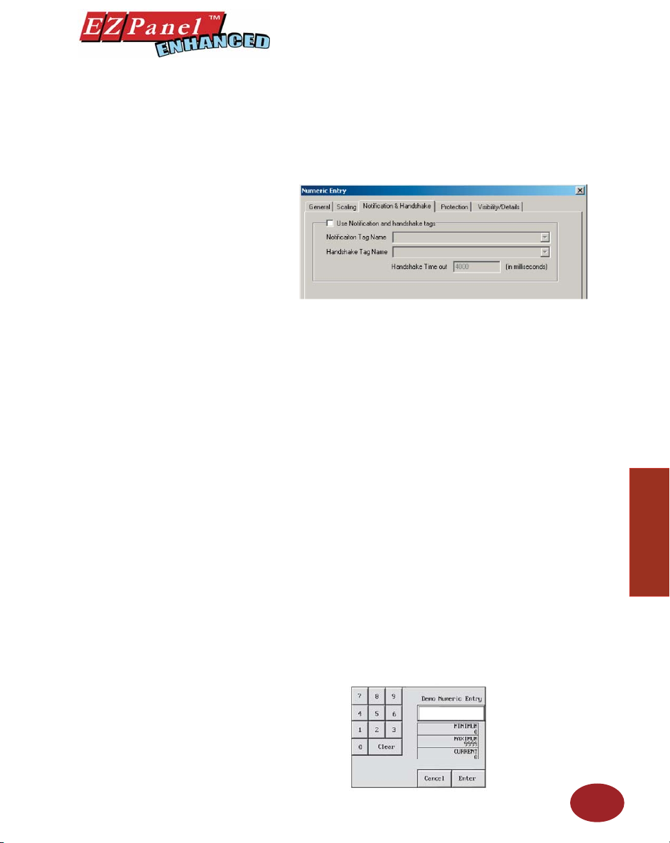
Editor Programming Software User Manual
Click on this tab if you want to confi gure a discrete tag that will notify the
panel when the numeric entry has been received. To let the operator know,
the keypad will automatically close when the value has been received.
1. Click in the box in front of Use Notifi cation and Handshake tags
2. In the Notifi cation Tag Name fi eld, enter or select a tag name
3. In the Handshake Tag Name fi eld, enter or select a tag name
4. Enter a Handshake Time out time in milliseconds. Enter a
Protection (see Button Object.)
to enable this option.
where the tag will notify a location that a numeric entry value has
been received.
where the tag will return a value to the panel that will close the
keypad thereby letting the operator know that the value was
received and entered.
number between 1 and 65535.
Visibility/Details (see Button Object.)
OK/Cancel/Help Buttons
• Click on OK button to save your selections and exit the dialog
• Click on Cancel button to exit the dialog box without saving
• Click on Help button to go to the Help Topic for that dialog box.
Place Object on the screen and size it.
• To size the Numeric Entry object, grab a handle and drag.
• To move the object, select it, click and hold left mouse button
This is an example of a SIGNED DECIMAL
Popup Keypad as it will display on your panel
Screen. If you enter an invalid value, press
the Clear (CLR) button and reenter.
box.
Objects
your selections.
and drag to where you want it to appear on the screen.
65
Page 78
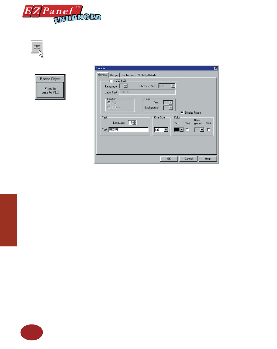
Recipe Object
Editor Programming Software User Manual
The Recipe object allows you to write preset values of up to 20 Tags to the
PLC to change the process. Thus, this feature can be used to download
“recipes” to the PLC.
To put a Label on the Recipe object button, perform the following
steps:
Objects
66
1. Click on the box in front of Label Text.
2. Use the UP/DOWN arrows after the Language box to select a
language number. (See section on Language, page 180.)
3. Select Character Size from the available choices.
4. Enter Label Text up to 40 characters.
5. Select the Position of the label, whether you want it to appear at
the Top or the Bottom of the object frame.
6. Select the Tex t and Background Color. Click on the down arrow
to view the color palette.
7. Display Frame is selected by default. If you do not want the
frame around the object to be visible, click on the box to deselect
(the box will be empty).
Enter Tex t:
Here you will enter the Text that will appear within the object, and control
how that text will appear.
1. Select the Language number (1–9) for the Text.
2. Type in what you want to appear within the button.
3. Select Character Size from the available choices
4. Select the Color of the Text and the Color of the Background.
5. If you want the Text or the Background to Blink, click on the
box below Blink to place a check mark indicating that the option
is enabled.
Page 79
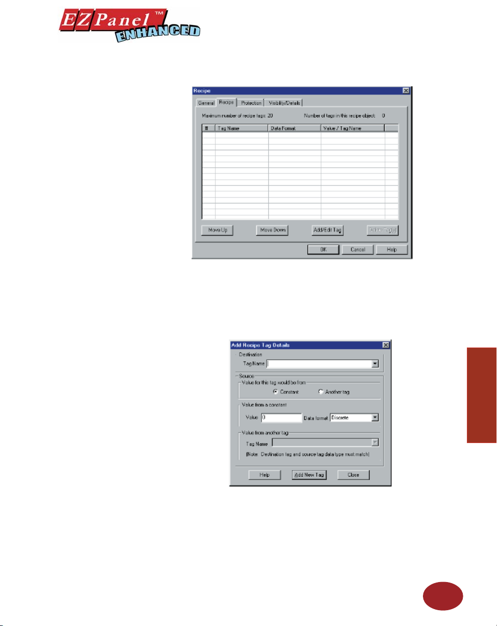
Editor Programming Software User Manual
Enter Tag Name and Register Values:
Pressing the Recipe button allows you to write values to several locations
at once. Click on the Recipe tab, to view the window above. This is where
the recipe tag database is displayed. You will enter the values to be written
to the PLC location as follows.
1. Click on the Add/Edit Tags button. The following window will
appear.
2. Under Destination, Tag Name, click on the down arrow to view
list of available tags (or enter a new name). Select the tag you
wish to use. If you enter a new tag name the Add New Tag Details
dialog will open. Enter the tag details.
3. The Destination tag type determines the data format.
4. Under Source, choose Constant (default) or Another tag for
the value.
5. If you choose Constant, the Value from a constant group will
67
Objects
Page 80

Editor Programming Software User Manual
6. Enter a Value that you want written to the register.
7. Select from the available Data Format choices (i.e., Unsigned
8. If you choose Another tag, the Value from another tag will be
9. Enter a new source tag or choose an existing tag from those
10. Repeat for the second entry. You may continue writing values
Note: If a Discrete tag is chosen, enter a 0 for OFF or a 1 for
Protection (see Button Object.)
Visibility/Details (see Button Object.)
OK/Cancel/Help Buttons
• Click on OK button to save your selections and exit the dialog
• Click on Cancel button to exit the dialog box without saving
• Click on Help button to go to the Help Topic for that dialog
Place Recipe object button on the screen and size it.
• To size the object, grab a handle and drag.
• To move the object, select it, click and hold left mouse button
be enabled and Value from another tag will be disabled.
Decimal, Signed Decimal, Octal or Hex.)
enabled and Value from a constant will be disabled.
available. Only the tags that are of the same data type as the
destination tag will be displayed.
for up to 20 Tags (locations).
ON.
box.
your selections.
box.
while dragging the object to where you want it placed on the
screen.
Objects
68
Page 81
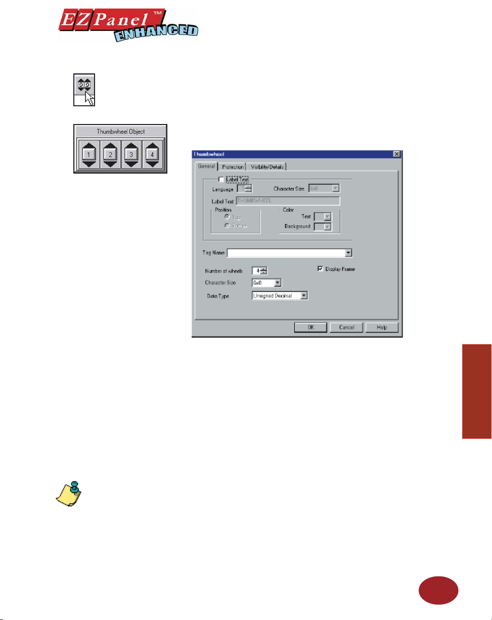
Editor Programming Software User Manual
Thumbwheel Object
NOTE: ONLY TWO TAG
TYPES are available for
the Thumbwheel object—
UNSIGNED_INT_16 (can
be UNSIGNED Decimal or
HEX Data type) and BCD_
INT_16.
The function of this object is similar to Numeric Entry Button. The
Thumbwheel object allows you to display a Thumbwheel keypad on the
panel. This button can be 1 to 5 digits. Using the popup thumbwheel, the
operator can change each digit separately. The operator presses the UP or
DOWN arrow to increment or decrement the value of each digit. Press the
enter button to write that value to the defi ned tag. This allows the operator
to assign a value to a specifi c PLC register.
To put a Label on the Thumbwheel object button, perform the following
steps:
1. Click on the box in front of Label Text.
2. Use the UP/DOWN arrows after the Language box to select a
language number. (See section on Language, page 180.)
3. Select Character Size from the available choices.
4. Enter Label Text up to 40 characters.
5. Select the Position of the label, whether you want it to appear
at the Top or the Bottom of the object frame.
6. Select the Tex t and Background Color. Click on the down arrow
to view the color palette.
7. Display Frame is selected by default. If you do not want the
frame around the object to be visible, click on the box to deselect
(the box will be empty).
Enter a Tag Name:
1. Enter a Tag Name or click on the down arrow and select the Tag
Name that you want the object to correspond to.
2. If the Tag Name is new, the Add New Tag Details dialog box
will appear where you will enter tag details. The Tag Name will
appear in the fi rst fi eld. Enter an Address String appropriate for
your type PLC and select the Data Type (from available choices).
Click on the OK button.
Objects
69
Page 82
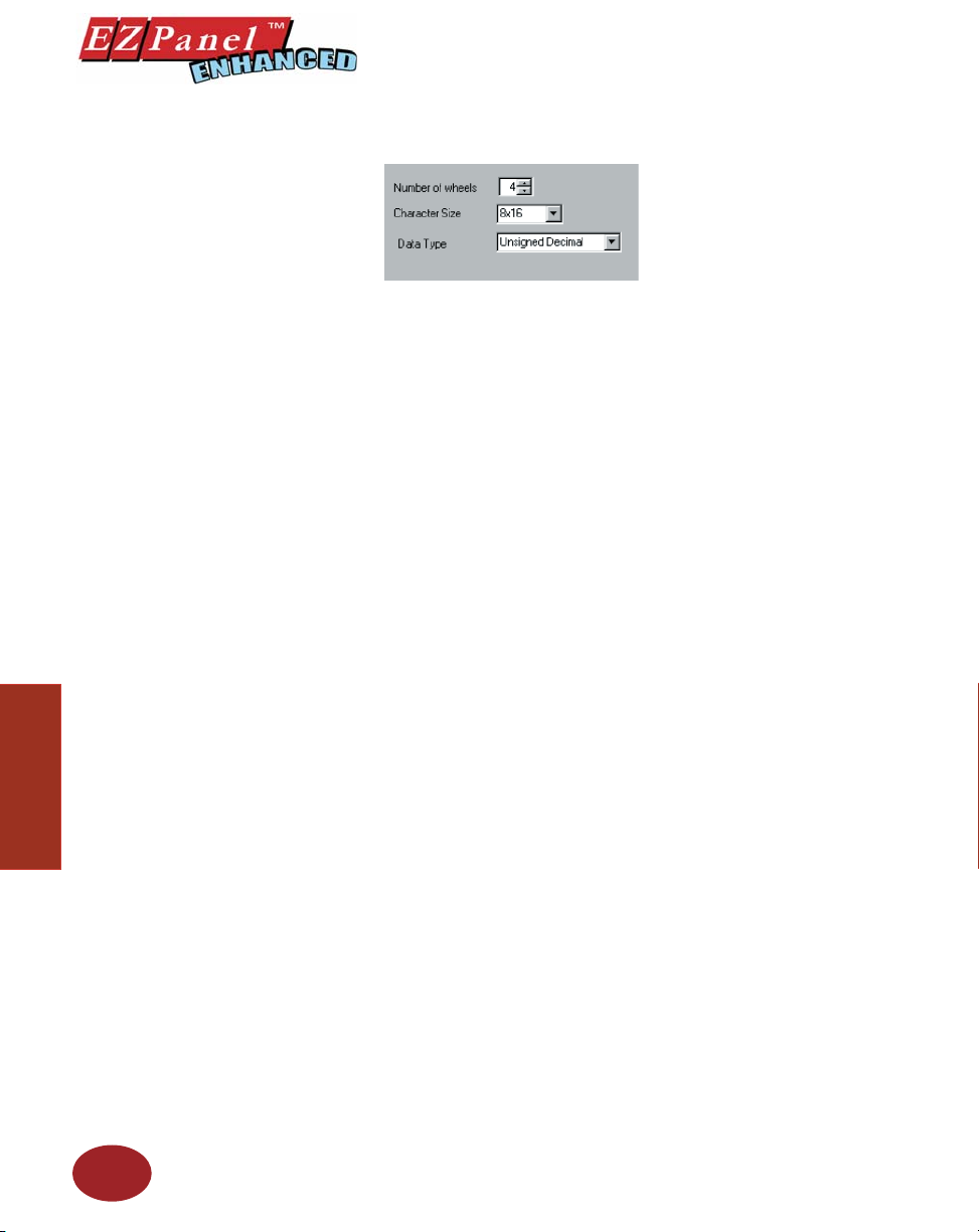
Editor Programming Software User Manual
Select Thumbwheel Format:
1. Select the Number of Wheels (from 1 to 5) for the object. You
2. Choose the size of the numbers (Character Size) that will appear
3. Select the Data Type of the numbers from the available
Protection (see Button Object.)
Visibility/Details (see Button Object.)
OK/Cancel/Help Buttons
• Click on OK button to save your selections and exit the dialog
• Click on Cancel button to exit the dialog box without saving
• Click on Help button to go to the Help Topic for that dialog box.
will only be able to use 4 digits (wheels) when using BCD or Hex
data types.
within the thumbwheels.
selections.
box.
your selections.
Objects
70
Place Thumbwheel object button on the screen and size it.
• To size object, grab a handle and drag the object to the size
that you want.
• To move the object, select it, click and hold left mouse while
dragging to where you want it to appear on the screen.
Page 83
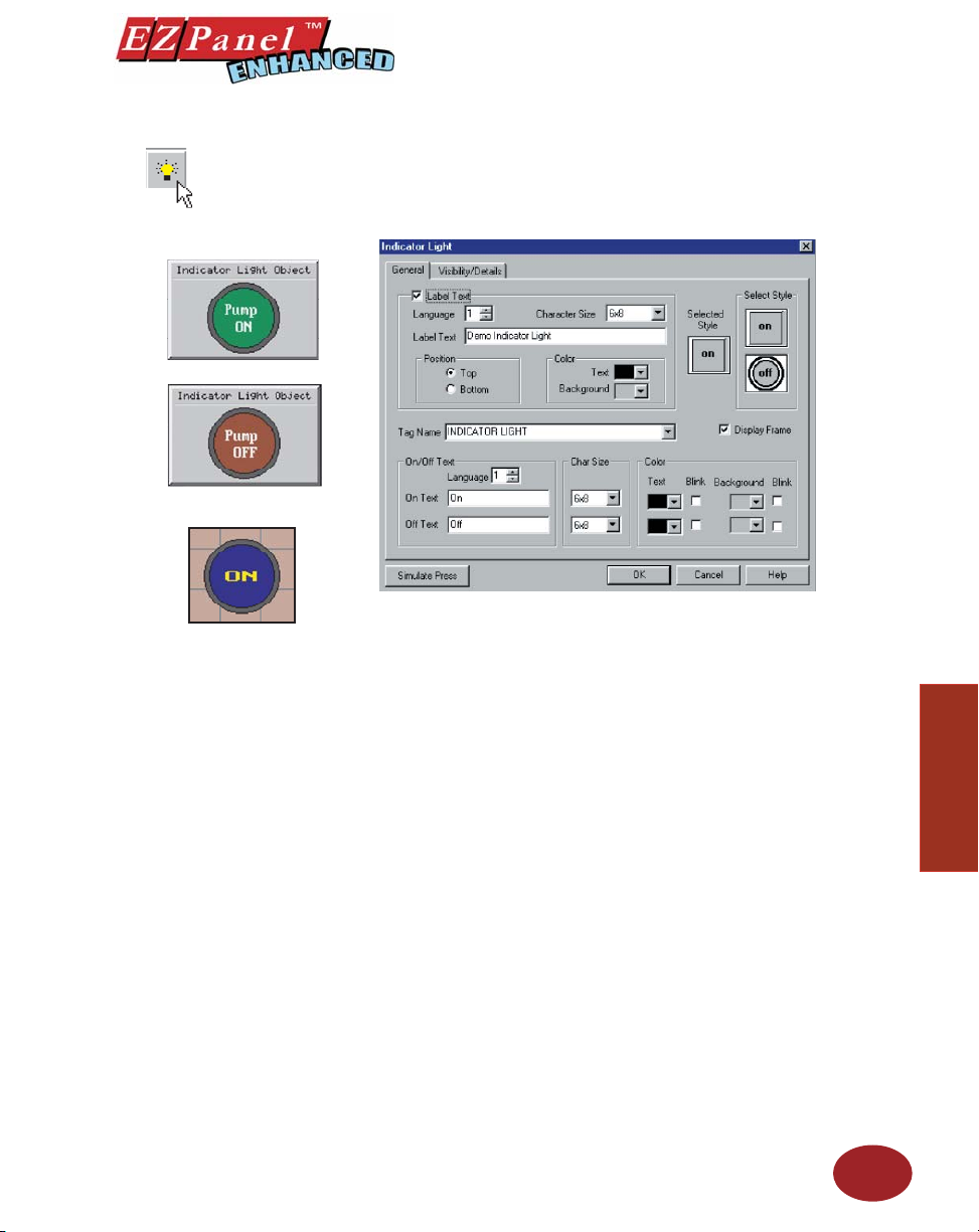
Indicator Light Object
No Frame
Editor Programming Software User Manual
An Indicator Light object allows you to monitor and display the state of a bit.
The Indicator Light reads the bit information and produces the appropriate
display. For example, the Indictor Light could display the status of a bit
linked to a push button.
To put a Label on the Indicator Light object, perform the following
steps:
1. Click on the box in front of Label Text.
2. Use the UP/DOWN arrows after the Language box to select a
language number. (See section on Language, page 180.)
3. Select Character Size from the available choices.
4. Enter Label Text up to 40 characters.
5. Select the Position of the label, whether you want it to appear at
the Top or the Bottom of the object frame.
6. Select the Tex t and Background Color. Click on the down arrow
to view the color palette.
7. Display Frame is selected by default. If you do not want the
frame around the object to be visible, click on the box to deselect
(the box will be empty).
Objects
To Choose an Indicator Light Style, perform the following steps:
1. Under Select Style, click on the style you prefer for the indicator
2. Your choice will appear under Selected Style.
Enter a Tag Name:
1. Enter a Tag Name or click on the down arrow and select the Tag
2. If the Tag Name is new, the Add New Tag Details dialog box will
light object you are creating.
Name that you want the Indicator Light to monitor.
appear where you will enter tag details. The Tag Name will appear
in the fi rst fi eld. Enter an Address String appropriate for your
type PLC. Click on the OK button.
71
Page 84

Editor Programming Software User Manual
Enter On/Off Text:
Here you will enter the Text that will appear within the object, and control
how that text will appear.
1. Select the Language number (1–9) for the On/Off Text.
2. Type in what you want to appear within the Indicator Light object
3. Select Character Size from the available choices.
4. Select the Color of the Text and the Color of the Background.
5. If you want the Te xt or the Background to Blink, click on the
Visibility/Details (See Button Object.)
OK/Cancel/Help Buttons
• Click on OK button to save your selections and exit the dialog
• Click on Cancel button to exit the dialog box without saving
• Click on Help button to go to the Help Topic for that dialog box.
Place Indicator Light object on the screen and size it.
• To size it grab a handle and drag it to the size that you want.
• To move the button, select it, click and hold left mouse button
for the On Text and for the Off Text (i.e., you might want to place
the words STOPPED and RUNNING inside the Indicator light,
instead of Off and On).
box below Blink to place a check mark indicating that the option
is enabled.
box.
your selections.
and drag to where you want it to appear on the screen.
Objects
72
Simulate Press
To Simulate Press, double click the object to bring up the object dialog
box. (You may have to drag the dialog box to see the object on the
programming screen.) Click on the Simulate Press button to see how the
Indicator Light object will display on the screen when pressed.
Page 85
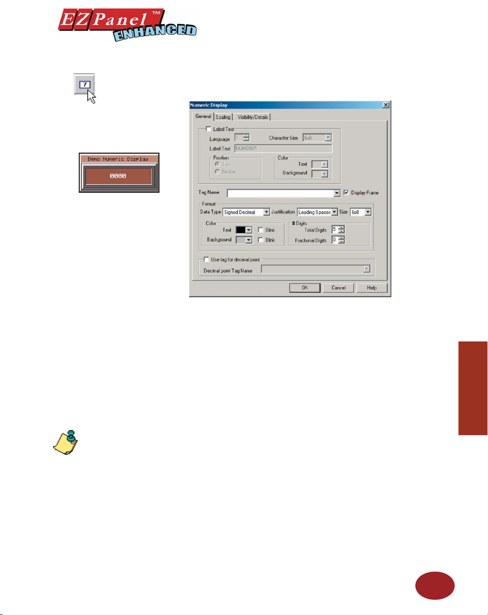
Numeric Display Object
NOTE: To edit the Address
String, with your cursor in
the Tag Name fi eld, click on
the right mouse button. The
EDIT TAG DETAILS screen
will appear.
Editor Programming Software User Manual
The Numeric Display object allows you to display a Tag value within a
frame on the screen.
To put a Label on the Numeric Display object, perform the following
steps:
1. Click on the box in front of Label Text.
2. Use the UP/DOWN arrows after the Language box to select a
language number. (See section on Language, page 180.)
3. Select Character Size from the available choices.
4. Enter Label Text up to 40 characters.
5. Select the Position of the label, whether you want it to appear
at the Top or the Bottom of the object frame.
6. Select the Tex t and Background Color. Click on the down arrow
to view the color palette.
7. Display Frame is selected by default. If you do not want the
frame around the object to be visible, click on the box to deselect
(the box will be empty).
Enter a Tag Name:
1. Enter a Tag Name or click on the down arrow and select the Tag
Name that you want the Numeric Display object to monitor.
2. If the Tag Name is new, the Tag Entry dialog box will appear where
you will enter tag details. The Tag Name will appear in the fi rst
fi eld. Enter an Address String appropriate for your type PLC
and select the Data Type (from available choices). Click on the
OK button.
Objects
73
Page 86
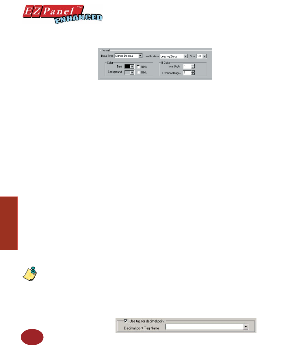
Editor Programming Software User Manual
Enter the Format of the Numeric Display:
The Data Type is dependent upon the Tag type. In turn, the Tag data type is
dependent upon the type of PLC you are using. Therefore, your selections
next to Data Type in this object will be limited by your Tag and PLC data
type. EZPanel Enhanced Editor Programming Software will automatically
limit your selections based on the PLC and Tag address format.
The Data Types, and their respective ranges, that may be available, are
as follows:
Signed 16 Decimal: -32768 to +32767
Signed 32 Decimal: -2147483648 to +2147483647
Unsigned 16 Decimal: 0 to 65535
Unsigned 32 Decimal: 0 to 4294967295
Octal 16: 0 to 177777
Octal 32: 0 to 37777777777
Hex 16: 0 to FFFF
Hex 32: 0 to FFFFFFFF
BCD 16: 0 to 9999
BCD 32: 0 to 99999999
Objects
74
NOTE: If a Decimal Point
tag is selected, the Fractional
Digits will not be used. The
number of fractional digits
will come from the value of
the tag.
1. Click on Data Type and select from the available choices.
2. Click on Justifi cation and select from the following: Left Justify,
Right Justify, or Leading Zeroes.
3. Click on Size and select from the available character sizes. (Click
on down arrow to view list of sizes.)
4. Under Color, click on down arrow to view the color palette for
Tex t. Click on any color to select.
5. Click on the box in front of Blink if you want your text characters
to blink.
6. Select color for Background and whether or not you want it to
Blink.
7. Click on Total Digits under # Digits. Here you will select
how many digits, from 1 to 10 (depending on the Data Type and
Tag Type), that you want to display.
8. If you want Fractional Digits, enter 1 through 10 here (select 0
for none). For example, if your maximum value is 999, you would
enter 3 under total digits. If your maximum value is 99.9, enter
3 under Total Digits and 1 under Fractional Digits.
9. If you want a tag to control the decimal points, click in the box
in front of Use tag for decimal point and then enter or select a
Decimal point Tag Name.
Page 87
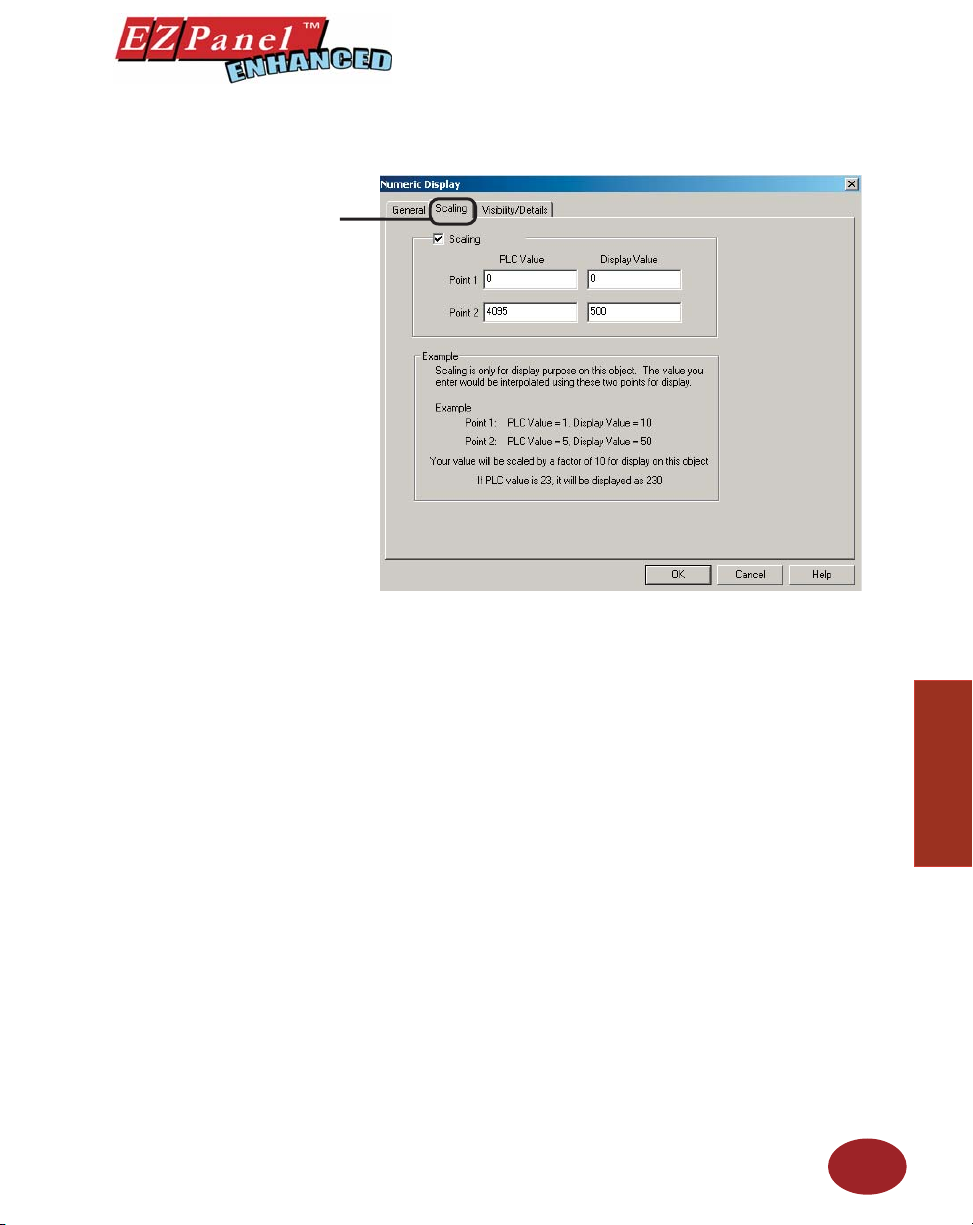
Click on the Scaling tab if
you want the Display Value
to be different than the PLC
Value.
Editor Programming Software User Manual
Scaling Tab
Under the Scaling tab, you can scale the value in the PLC to another value
on the Numeric Display. Enter Point 1 and Point 2 PLC Values. Scale
these values by entering the Point 1 and Point 2 Display Values.
For example, say the PLC values are an analog value of 0–4095, and
represent a range of 0–500 PSI.
Enter a PLC Value (Point 1) = 0 and a Display Value (Point 1) =
0 (PSI)
Enter a PLC Value (Point 2) = 4095 and a Display Value (Point
2) = 500 (PSI)
If the PLC Value is then = 1024, the Display Value will be 125.
Visibility/Details (See Button Object.)
OK/Cancel/Help Buttons
• Click on OK button to save your selections and exit the dialog
box.
• Click on Cancel button to exit the dialog box without saving
your selections.
• Click on Help button to go to the Help Topic for that dialog box.
Place Object on the screen and size it.
• To size the object, grab a handle and drag it to the size you
want.
• To move the button, select it, click and hold left mouse button
and drag to the area on the screen that you want it to appear.
75
Objects
Page 88
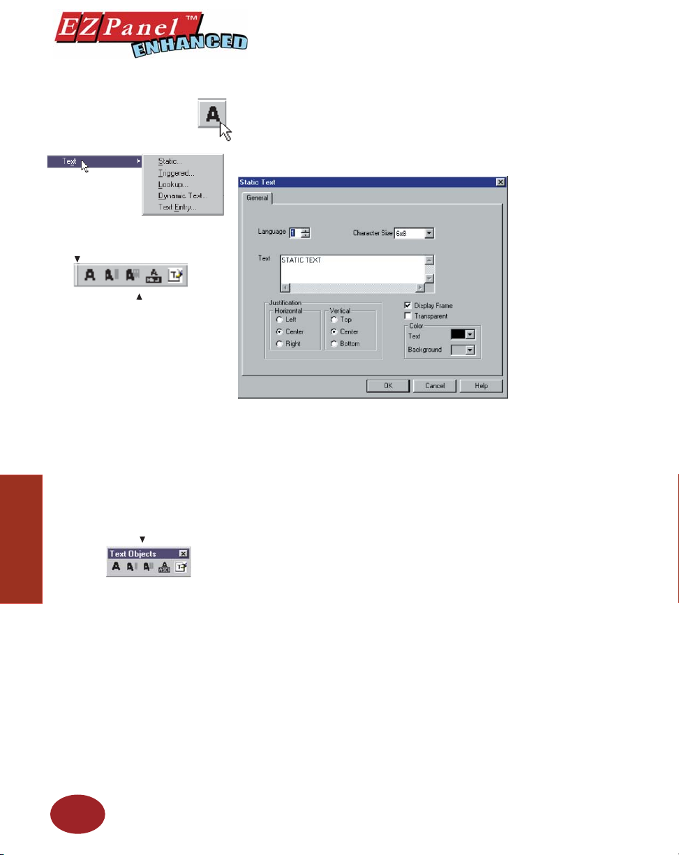
Text Objects
Grab a handle with your
mouse
The Text Object Tool Bar as
it originally appears in the
programming window.
You can move the tool bar to other
locations on the programming
window by clicking and holding
the left mouse button on the
handle bar (see above), and
dragging to where you want it
to appear in the Programming
Window.
The Text Tool bar as it appears on
the programming screen.
Objects
Editor Programming Software User Manual
Static Text
This object allows you to place text anywhere on the screen to provide
information, screen description, etc. You can choose whether or not to display
a frame around the text and whether or not you want it to be transparent.
Under the General tab you will make the following selections:
1. Select a Language (1–9) that you want the text to display in.
2. Select a Character Size from those available (e.g., 6 x 8, 8 x 16,
8 x 32).
3. Type in the Text as you want it to display on the panel screen. The
text can be up to 500 characters and wraps within the frame.
4. Select Horizontal (Left, Center, or Right) and Vertical (Top,
Center, or Bottom) Justifi cation for the text. Default for both is
“Center”.
5. If you want the text to appear within a frame, click on the box in
front of Display Frame to enable. If you want to see through
the text and/or frame to what lies underneath, click on the box in
front of Transparent.
6. Select the Text and Background Color from the available choices.
Default Text color is black and the default Background color is
gray.
OK/Cancel/Help Buttons
• Click on OK button to save your selections and exit the dialog
box.
• Click on Cancel button to exit the dialog box without saving
your selections.
• Click on Help button to go to the Help Topic for that dialog box.
Place Text Object on the screen and size it.
• To size it grab a handle and drag.
• To move the button, select it, click and hold left mouse button
and drag to where you want it to appear on the screen.
76
Page 89
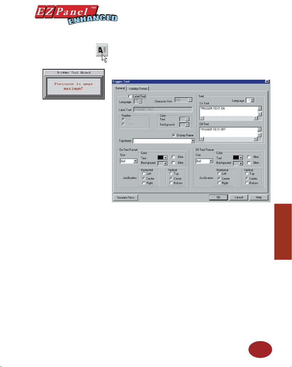
Editor Programming Software User Manual
Triggered Text
The Triggered Text object monitors a bit to display different text strings for
“ON” and “OFF” conditions. This would be used in applications where you
want to provide a message or a description of the process or condition.
To put a Label on the Triggered Text object, perform the following
steps:
1. Click on the box in front of Label Text.
2. Use the UP/DOWN arrows after the Language box to select a
language number. (See section on Language, page 180.)
3. Select Character Size from the available choices.
4. Enter Label Text up to 40 characters.
5. Select the Position of the label, whether you want it to appear
at the Top or the Bottom of the object frame.
6. Select the Tex t and Background Color. Click on the down arrow
to view the color palette.
7. Display Frame is selected by default. If you do not want the
frame around the text to be visible, click on the box to deselect
(the box will be empty).
Enter the Text you want to appear on the display when ON and when
OFF:
1. Select the Language number for the On Text and the Off Text.
2. Type in what you want to appear within the frame for the On Text
and for the Off Text (up to 500 characters).
77
Objects
Page 90
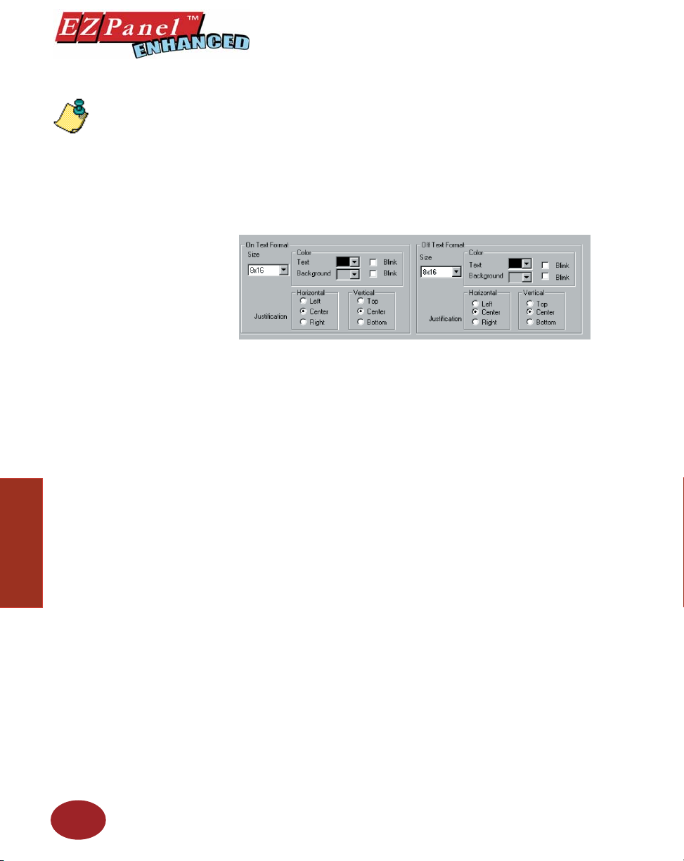
NOTE: To edit the Address
String, with your cursor in
the Tag Name fi eld, click on
the right mouse button. The
EDIT TAG DETAILS screen
will appear.
Editor Programming Software User Manual
Enter a Tag Name:
1. Enter a Tag Name or click on the down arrow and select the Tag
Name that you want the Trigger Text object to monitor.
2. If the Tag Name is new, the Add New Tag Details dialog box
will appear where you will enter tag details. The Tag Name will
appear in the fi rst fi eld. Enter an Address String appropriate for
your type PLC. Click on the OK button.
Make selections for On Text and Off Text Format:
Under On Text Format:
1. Select Size from the available choices.
2. Select the Color of the Text and the Color of the Background.
3. If you want the Text or the Background to Blink, click on the box
below Blink to place a check mark indicating that the option is
enabled.
4. Choose the Horizontal and Vertical Justifi cation for the On Text.
For Horizontal justifi cation, click in front of one of the following:
Left, Center, or Right. For Vertical Justifi cation, click in front of
Top , Center, or Bottom.
Objects
78
Under Off Text Format, repeat the steps above.
Visibility/Details (See Button Object.)
OK/Cancel/Help Buttons
• Click on OK button to save your selections and exit the dialog
box.
• Click on Cancel button to exit the dialog box without saving
your selections.
• Click on Help button to go to the Help Topic for that dialog box.
Page 91
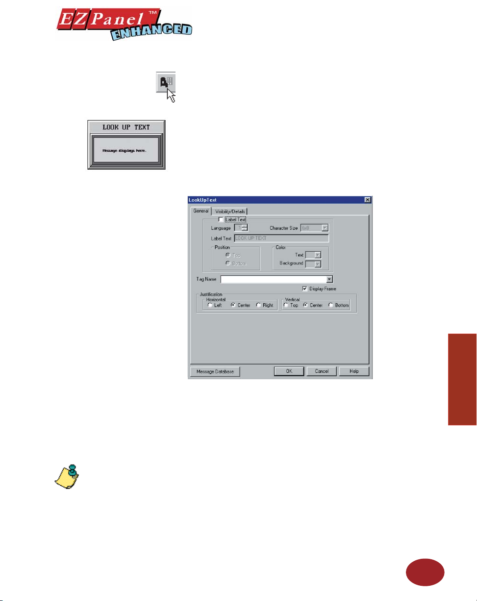
Editor Programming Software User Manual
Lookup Text
Lookup Text is an object that is created to display pre-programmed
messages within a frame on the panel screen. These pre-programmed
messages are stored in the “ Message Database.” It displays one message
at a time. (Click on the Message Database button at the bottom of the dialog
box to program messages in the database.)
A Value corresponding to the Tag Name is the Message Number that will
be displayed inside the frame of the Lookup Text. Each message designed
in the Message Database is numbered from 1 to 999. So, if the Value
corresponding to the Tag Name is 10, Message Number 10 will be displayed
within the Lookup Text Frame.
NOTE: To edit the Address
String, with your cursor in
the Tag Name fi eld, click on
the right mouse button. The
EDIT TAG DETAILS screen
will appear.
Objects
To put a Label on the Lookup Text object, perform the following
steps:
1. Click on the box in front of Label Text.
2. Use the UP/DOWN arrows after the Language box to select a
language number. (See section on Language, page 180.)
3. Select Character Size from the available choices.
4. Enter Label Text up to 40 characters.
5. Select the Position of the label, whether you want it to appear
at the Top or the Bottom of the object frame.
6. Select the Tex t and Background Color. Click on the down arrow
to view the color palette.
7. Display Frame is selected by default. If you do not want the
frame around the text to be visible, click on the box to deselect
(the box will be empty).
79
Page 92

NOTE: The value
corresponding to the Tag
Name tells which message
number from the message
database is to be displayed.
Editor Programming Software User Manual
Enter a Tag Name:
1. Enter a Tag Name or click on the down arrow and select the Tag
Name from the available choices.
2. If the Tag Name is new, the Add New Tag Details dialog box
will appear where you will enter tag details. The Tag Name will
appear in the fi rst fi eld. Enter an Address String appropriate for
your type PLC and select the Data Type (from available choices).
Click on the OK button.
Select Message Text Justifi cation:
Messages created in the Lookup Text object are saved in the Message
Database. (See page 176 for Message Database setup.) This is a local
attribute for each Lookup Text object. So, the same message in one Lookup
text object can be left justifi ed within the frame while in another Lookup Text
object, it can be right justifi ed.
Objects
1. Select the Horizontal and Vertical Justifi cation for the text as it
will appear within the frame when displayed on the panel.
2. To create a message, click on the Message Database button.
Visibility/Details (See Button Object.)
OK/Cancel/Help Buttons
• Click on OK button to save your selections and exit the dialog
box.
• Click on Cancel button to exit the dialog box without saving
your selections.
• Click on Help button to go to the Help Topic for that dialog box.
Place Lookup Text object on the screen and size it.
• To size it grab a handle and drag.
• To move the button, select it, click and hold left mouse button
and drag.
Message Database
The Message Database stores programmed messages that can be
accessed by the Lookup Text object. Create messages in the database dialog
box to be used by the Lookup Text object. Up to 999 messages (limited by
available memory) may be stored in the database. Each message may be
up to 200 characters and you can choose various message attributes such
as, Character Size, Text Color, Background Color, Blink, and Language.
Use the scroll bar to view more messages. To add a new message, or edit an
existing message, click on Add/Edit button, then click in the Message Text
fi eld and type your message. To delete a Message, select the message text,
then click on the Delete button. A screen will appear asking you to confi rm
the delete message. Click on OK to delete message.
80
For more information on the Message Database — see page
176.
Page 93
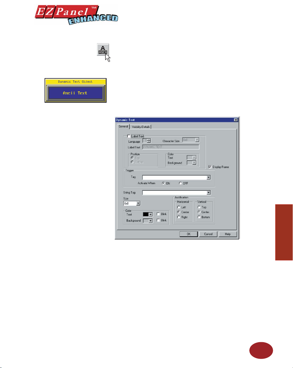
Editor Programming Software User Manual
Dynamic Text
The Dynamic Text object will allow you to display the characters from
ASCII values stored in a Tag. The tag will read a block of registers in the
PLC. Each 16-bit register in the PLC can contain 2 ASCII characters. The
maximum number of PLC registers in the block is 20 (a maximum of 40 ASCII
characters). This object allows you to place text anywhere on the screen
to provide information. It is typically used for displaying part numbers, VIN
numbers, or production numbers. Dynamic Text is triggered by a bit Tag in
the PLC. You choose whether the Text is triggered by the bit when it is in
the ON state or the OFF state. The Dynamic Text object will then display
a text string that is programmed in the PLC.
To put a Label on the Dynamic Text object, perform the following
steps:
1. Click on the box in front of Label Text.
2. Use the UP/DOWN arrows after the Language box to select a
language number. (See section on Language, page 180.)
3. Select Character Size from the available choices.
4. Enter Label Text up to 40 characters.
5. Select the Position of the label, whether you want it to appear at
the Top or the Bottom of the object frame.
6. Select the Tex t and Background Color. Click on the down arrow
to view the color palette.
7. Display Frame is selected by default. If you do not want the
frame around the text to be visible, click on the box to deselect
(the box will be empty).
Choose the Trigger Tag Name:
This Tag allows the EZPanel Enhanced to monitor a bit in the PLC and
display text based on the ASCII values in a block of PLC registers.
81
Objects
Page 94
Editor Programming Software User Manual
NOTE: To edit the Address
String, with your cursor in
the Tag Name fi eld, click on
the right mouse button. The
EDIT TAG DETAILS screen
will appear.
NOTE: For a list of ASCII
Characters that EZPanel
Enhanced Supports, see
Appendix B.
1. Select the Trigger Tag Name by clicking on the down arrow
to display the list or enter a Tag Name in the entry fi eld. If the
Tag Name is new, the ADD NEW TAG DETAILS dialog box will
appear. The Tag Name will appear in the fi rst fi eld. Enter an
Address String appropriate for your type PLC. Click on the OK
button.
2. Choose to Activate When ON or Activate When OFF. If you
choose ON, the Text will display when the bit is ON. When the
bit is OFF, the Text will disappear.
Choose the String Tag Name:
The String Tag is the PLC register location where the values are read and
displayed in a character string. The string may be up to 40 characters long.
The Address String is the beginning register for the text.
Choose the Tag Name by clicking on the down arrow to display the list of
Tags or type in the Tag Name in the entry fi eld. If the Tag Name is new,
the ADD NEW TAG DETAILS dialog box will appear where you will enter
tag details. The Tag Name will appear in the fi rst fi eld. Enter an Address
String appropriate for your type PLC (ASCII STRING is the only choice).
Click on the OK button.
Select the Dynamic Text Characteristics:
1. Select the Character Size from the available choices.
2. Select the Color of the Text and Background and whether or
not they will Blink.
3. Choose the Justifi cation of the Text that is displayed within
the frame. Choose both Horizontal (Left, Center, or Right) and
Vertical (Top, Center, or Bottom) justifi cation for the Text within
the frame.
Objects
82
Visibility/Details (See Button Object.)
OK/Cancel/Help Buttons
• Click on OK button to save your selections and exit the dialog
box.
• Click on Cancel button to exit the dialog box without saving
your selections.
• Click on Help button to go to the Help Topic for that dialog box.
Place object on the screen and size it.
• To size the object, grab a handle and drag it to the size you
want.
• To move the object, select it, click and hold left mouse button
and drag to where you want it to appear on the screen.
Page 95
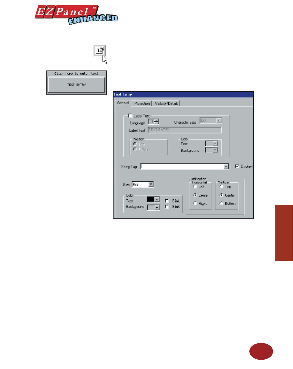
Editor Programming Software User Manual
Text Entry
The Text Entry object, when pressed on the panel, brings up a
character entry (alphanumeric) keypad. This allows the operator
to enter text up to 40 characters to send to a Tag assigned to an
address in a PLC. It has many uses, some of which may be: to
send part numbers or production numbers to a PLC, or to send a
message to a PLC that will, in turn, route it to one or more plant
fl oor message display(s).
To put a Label on the Text Entry object, perform the following
steps:
1. Click on the box in front of Label Text if you want a label
for your object.
2. Use the UP/DOWN arrows after the Language box to
select a language number. (See section on Language,
page 180.)
3. Select Character Size from the available choices.
4. Enter Label Text up to 40 characters.
5. Select the Position of the label, whether you want it to
appear at the Top or the Bottom of the object frame.
6. Select the Text and Background Color. Click on the
down arrow to view the color palette.
7. Display Frame is selected by default. If you do not want
the frame around the text to be visible, click on the box to
deselect (the box will be empty).
83
Objects
Page 96
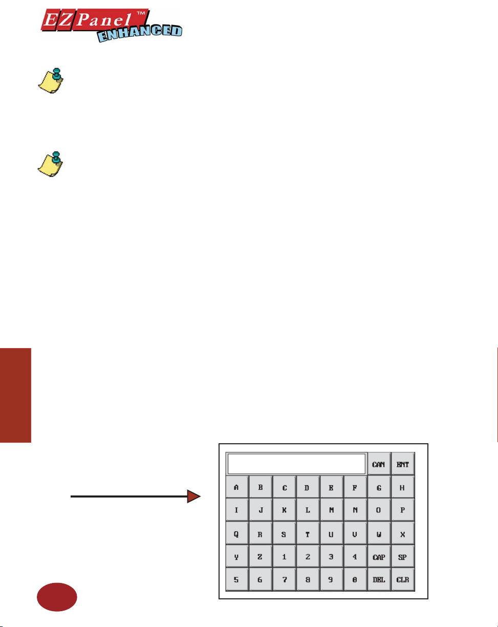
Editor Programming Software User Manual
NOTE: To edit the Address
String, with your cursor in
the Tag Name fi eld, click
on the right mouse button.
The EDIT TAG DETAILS
screen will appear.
NOTE:
1. For a list of ASCII
Characters that EZPanel
Enhanced Supports, see
Appendix B.
2. Each ASCII character
uses 1 byte of data. There
are 2 characters per register. 40 character maximum
uses 20 consecutive registers. The Address String
is the fi rst register of the
consecutive register block.
Objects
This is the Popup ( alphanumeric) Keypad
that displays on the EZPanel Enhanced
touchscreen when the Text Entry object
is pressed.
Choose the String Tag Name:
The String Tag represents the PLC locations where the values are
sent. The string may be up to 40 characters long.
1. Choose the Tag Name by clicking on the down arrow to
display the list of Tags or type in the Tag Name in the entry
fi eld. If the Tag Name is new, the Add New Tag Details
dialog box will appear where you will enter tag details. The
Tag Name will appear in the fi rst fi eld. Enter an Address
String appropriate for your type PLC. (ASCII STRING is
only choice available.) Select the Number of Characters.
Click on the OK button.
Select the String Characteristics:
1. Select the Character Size from the available choices.
2. Select the Color of the Tex t and Background and whether
or not they will Blink.
3. Choose the Justifi cation of the Te xt that is displayed
within the frame. Choose both Horizontal (Left, Center,
or Right) and Vertical (Top, Center, or Bottom) justifi cation
for the Text within the frame.
Protection (See Button Object.)
Visibility/Details (See Button Object.)
OK/Cancel/Help Buttons
• Click on OK button to save your selections and exit the
dialog box.
• Click on Cancel button to exit the dialog box without
saving your selections.
• Click on Help button to go to the Help Topic for that
dialog box.
84
Page 97
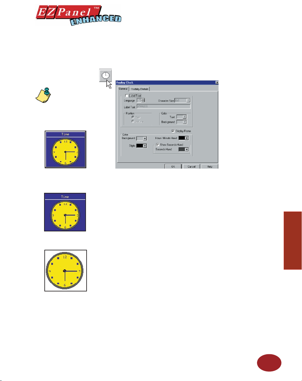
Editor Programming Software User Manual
Clock Object
NOTE: See page 163 to set
up the Clock Attributes.
Clock with Frame and
Label
Clock with Label, NO
Frame
The Clock object allows you to display a real time clock, showing
the current date, time, or both (analog clock displays time only.) It
can display as either an Analog or Digital Clock.
Analog Clock
To put a Label on the Clock object, perform the following
steps:
1. Click on the box in front of Label Text if you want a label
for your object.
2. Use the UP/DOWN arrows after the Language box to
select a language number. (See Language section, page
180.)
3. Select Character Size from the available choices.
4. Enter Label Text up to 40 characters.
5. Select the Position of the label, whether you want it to
appear at the Top or the Bottom of the object frame.
6. Select the Te xt and Background Color. Click on the
down arrow to view the color palette.
7. Display Frame is selected by default. If you do not want
the frame around the clock to be visible, click on the box
to deselect (the box will be empty).
Objects
Clock with NO Frame,
NO Label
To Choose how the Analog Clock will appear, perform the
following steps:
1. Under Color, choose the color of the Background (face
of the clock), Digits, and Hour/Minute Hand.
2. Select whether or not you want the Second Hand to
Display and the Color, if enabled.
Visibility/Details (See Button Object.)
OK/Cancel/Help Buttons
• Click on OK button to save your selections and exit the
dialog box.
85
Page 98
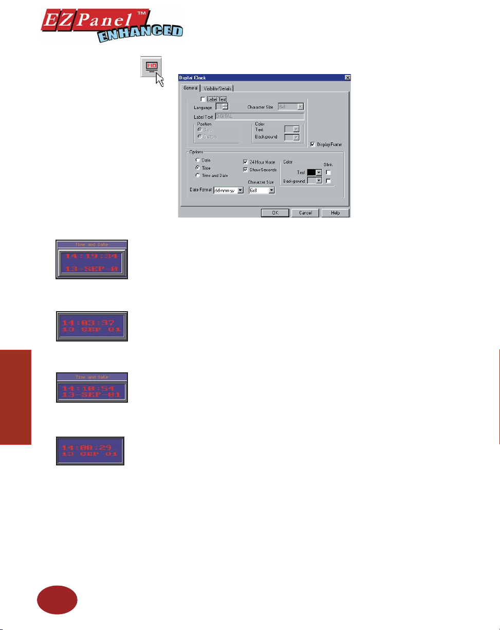
Clock with Frame and
Label
Clock with Frame, NO
Label
Clock with Label, NO
Objects
Frame
Clock with NO Frame,
NO Label
Editor Programming Software User Manual
Digital Clock
To put a Label on the Clock object, perform the following
steps:
1. Click on the box in front of Label Text if you want a label
for your object.
2. Use the UP/DOWN arrows after the Language box to
select a language number. (See Language section, page
180.)
3. Select Character Size from the available choices.
4. Enter Label Text up to 40 characters.
5. Select the Position of the label, whether you want it to
appear at the Top or the Bottom of the object frame.
6. Select the Text and Background Color. Click on the
7. Display Frame is selected by default. If you do not want
To choose how the Digital Clock will appear, perform the following steps:
1. Under Options, choose to display just the Date, just the
2. Select whether or not you want the Time to be displayed in
3. Choose the Date Format from the available choices and
4. Under Color, click on the down arrow next to Tex t and
5. Click on the box under Blink if you want the Background
down arrow to view the color palette.
the frame around the clock to be visible, click on the box
to deselect (the box will be empty).
Time, or both Time and Date.
24-Hour Mode and whether or not to Show Seconds.
the Character Size.
Background to view the color palette. Click on a color
swatch to select.
or Text to Blink.
Visibility/Details (See Button Object.)
OK/Cancel/Help Buttons
86
Page 99
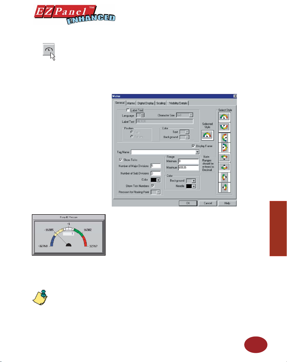
Meter Object
Editor Programming Software User Manual
A Meter object is used to display an analog gauge, such as a speed-
ometer. The meter consists of a data tag, a data type, data value
range, location of the meter on the screen, the sweep direction for
the needle, the needle color, and the number of ticks to display.
In simulating an analog gauge, the Meter object displays a needle
that sweeps through an arc as the tag value changes. Tick marks
NOTE: To edit the Address
String, with your cursor in
the Tag Name fi eld, click
on the right mouse button.
The EDIT TAG DETAILS
screen will appear.
are displayed along the arc.
To put a Label on the Meter object, perform the following
steps:
1. Click on the box in front of Label Text if you want a label
for your object.
2. Use the UP/DOWN arrows after the Language box to
select a language number. (See Language section, page
180.)
3. Select Character Size from the available choices.
4. Enter Label Text up to 40 characters.
5. Select the Position of the label, whether you want it to
appear at the Top or the Bottom of the object frame.
6. Select the Tex t and Background Color. Click on the
down arrow to view the color palette.
7. Click on a Style under Select Style.
8. Display Frame is selected by default. If you do not want
the frame around the Meter to be visible, click on the box
to deselect (the box will be empty).
87
Objects
Page 100
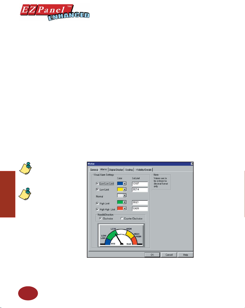
Editor Programming Software User Manual
Enter a Tag Name:
1. Enter a Tag Name or click on the down arrow and select
the Tag Name from the available choices.
2. If the Tag Name is new, the Tag Entry dialog box will
appear where you will enter tag details. The Tag Name
will appear in the fi rst fi eld. Enter an Address String
appropriate for your type PLC and select the Data Type
(from available choices). Click on the OK button.
Make the following selections to Format your meter:
1. If you want to show tick marks on your meter, click on box
in front of Show Ticks to enable.
2. Next select the Number of Major Divisions and the
Number of Sub (Minor) Divisions to display (maximum
for each is 20).
3. Click on the down arrow next to Color to view the color
palette for the Tick marks. Place the cursor over a color,
and click to select.
4. If you want to show numbers indicating the value of a
particular Tick mark, click on the box behind Show Tick
Numbers.
5. If you have selected a Floating Point Tag, you may enable
the Precision for Floating Point object. This will allow
Objects
88
NOTE: When entering
limits, the ranges cannot
overlap!
NOTE: These visual alarm
settings are only for display
on the meter, and are not
related to actual alarms in
the alarm database.
you to display the value of a tick mark on the meter with
up to 5 decimal points.
6. Select the Minimum and Maximum Range of the values
represented in the meter display. Ranges should be en-
 Loading...