

Page 1
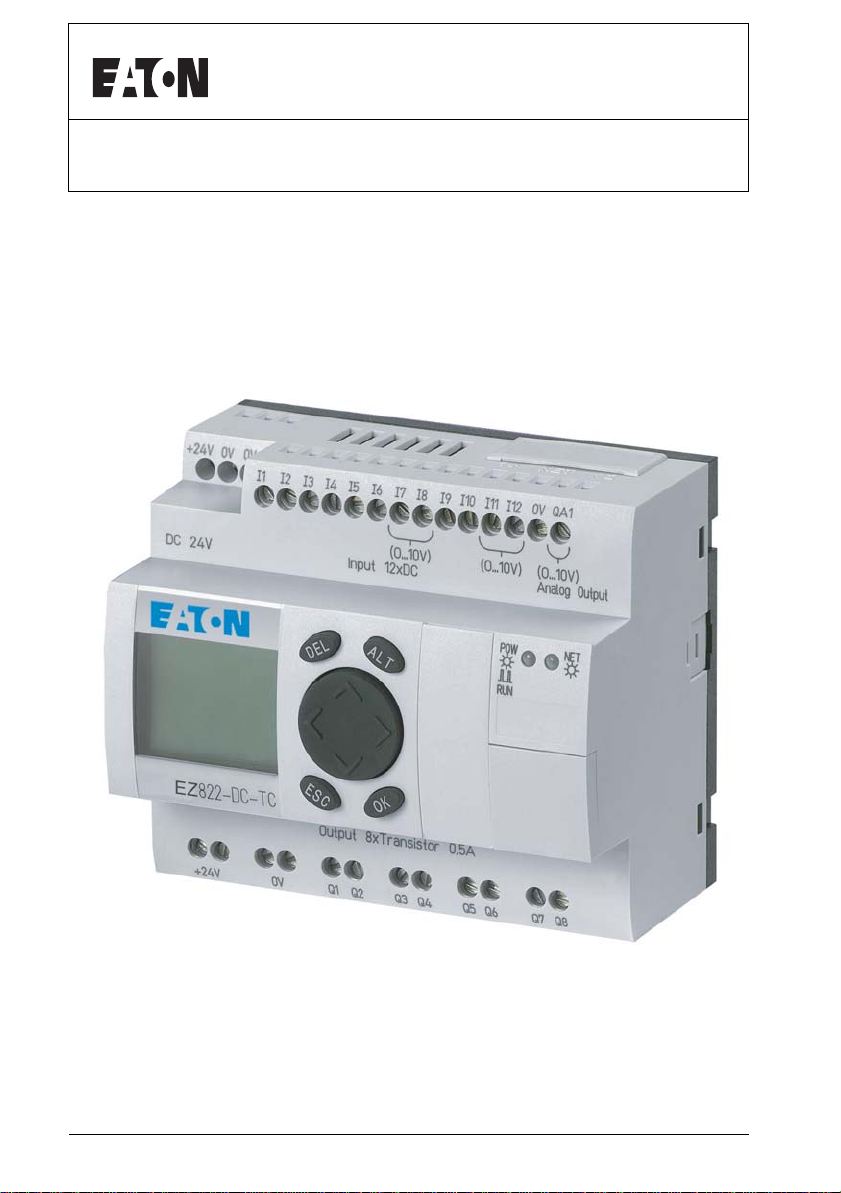
EZ800 Series
Re-Order from
omegamation.com
Omegamation
TM
1-888-55-OMEGA
1-888-55-66342
1-888-55-66342
User Manual
April 2005
For more information visit: www.EatonElectrical.comMN05013004E
Page 2

Page 3

Warning!
Dangerous electrical voltage!
Before commencing the installation
• Disconnect the power supply of the device.
• Ensure that devices cannot be accidentally
restarted.
• Verify isolation from the supply.
• Short circuit to earth.
• Cover or enclose neighboring units that
are live.
• Follow the engineering instructions (AWA)
of the device concerned.
• Only suitably qualified personnel in
accordance with EN 50110-1/-2 (VDE 0105
Part 100) may work on this device/system.
• Before installation and before touching
the device ensure that you are free of
electrostatic charge.
• The functional earth (FE) must be
connected to the protective earth (PE) or
to the potential equalization. The system
installer is responsible for implementing this
connection.
• Connecting cables and signal lines should
be installed so that inductive or capacitive
interference does not impair the automation
functions.
• Install automation devices and related
operating elements in such a way that they
are well protected against unintentional
operation.
• Suitable safety hardware and software
measures should be implemented for the
I/O interface so that a line or wire breakage
on the signal side does not result in
undefined states in the automation devices.
• Ensure a reliable electrical isolation of the
low voltage for the 24 volt supply. Only
use power supply units complying with
IEC 60364-4-41 (VDE 0100 Part 410) or HD
384.4.41 S2.
• Deviations of the mains voltage from the
rated value must not exceed the tolerance
limits given in the specifications, otherwise
this may cause malfunction and dangerous
operation.
• Emergency stop devices complying with
IEC/EN 60204-1 must be effective in all
operating modes of the automation
devices.Unlatching the emergency-stop
devices must not cause restart.
Eaton
Safety instructions
For more information visit: www.EatonElectrical.comMN05013004E I
Page 4

• Devices that are designed for mounting in
housings or control cabinets must only be
operated and controlled after they have
been installed with the housing closed.
Desktop or portable units must only be
operated and controlled in enclosed
housings.
• Measures should be taken to ensure the
proper restart of programs interrupted after
a voltage dip or failure. This should not
cause dangerous operating states even for
a short time. If necessary, emergency-stop
devices should be implemented.
• Wherever faults in the automation system
may cause damage to persons or property,
external measures must be implemented to
ensure a safe operating state in the event of
a fault or malfunction (for example, by
means of separate limit switches,
mechanical interlocks etc.).
For more information visit: www.EatonElectrical.com MN05013004EII
Page 5

Contents
About This Manual 9
Device designation 9
Reading conventions 10
1 EZ800 Control Relay 11
Target readership 11
Proper use 11
– Improper use 11
Overview 12
Device overview 14
– EZ basic units at a glance 14
– EZ800 type references 15
EZ operation 16
– Buttons 16
– Moving through menus and choosing values 16
– Selecting main and system menu 17
– EZ800 Control Relay status display 17
– Status display for local expansion 18
– EZ800 Control Relay advanced Status display 18
– EZ800 Control Relay LED display 19
– Menu structure 20
– Selecting or toggling between menu items 25
– Cursor display 26
– Setting values 26
2 Installation 27
Mounting 27
Connecting the expansion device 30
Terminals 31
– Tools 31
– Cable cross-sections 31
Network cables and plug 31
Connecting the power supply 31
– DC basic units 34
For more information visit: www.EatonElectrical.com 1MN05013004E
Page 6

Contents
– Cable protection 35
Connecting the inputs 35
– Connecting the AC inputs 35
– Connecting the EZ-DC 40
Connecting the outputs 46
Connecting relay outputs 47
– EZ8..-..-RC. 47
– EZ6..-..-RE 48
– EZ2..-RE 48
Connecting transistor outputs 49
– EZ8..-DC-TC, EZ6..-DC-TE 49
Connecting analog outputs 51
– Connecting servo valves 51
– Setpoint entry for a drive 52
Connecting the NET network 52
– Accessories 52
– Cable length and cross-sections 54
– Plugging and unplugging network cables 56
Expanding inputs/outputs 58
– Local expansion 59
– Remote expansion 60
3 Commissioning 61
Switching on 61
Setting the menu language 61
EZ operating modes 62
Creating your first circuit diagram 63
– Starting point Status display 65
– Circuit diagram display 66
– From the first contact to the output coil 67
– Wiring 68
– Testing the circuit diagram 70
– Deleting the circuit diagram 73
– Fast circuit diagram entry 73
Configuring an EZ-NET network 74
– Entering the network station number 75
– Entering network stations 76
– Configuring an EZ-NET network 77
– Changing the EZ-NET network configuration 78
– Displaying the Status display of other stations 79
For more information visit: www.EatonElectrical.com MN05013004E2
Page 7

Contents
4 Wiring with EZ800 Control Relay 81
EZ800 Control Relay operation 81
– Buttons for drawing circuit diagrams and
function block usage 81
– Operation 82
– Usable relays and function blocks (coils) 90
– Markers, analog operands 93
– Number formats 95
– Circuit diagram display 96
– Saving and loading programs 97
Working with contacts and relays 99
– Creating and modifying connections 102
– Inserting and deleting a circuit connection 104
– Saving circuit diagrams 105
– Aborting circuit diagram entry 105
– Searching for contacts and coils 105
– “Go to” a circuit connection 106
– Deleting the rung 106
– Switching via the cursor buttons 107
– Checking the circuit diagram 108
– Function block editor 109
– Checking function blocks 113
– Coil functions 114
Function blocks 119
– Analog value comparator/threshold value switch 121
– Arithmetic function block 124
– Data block comparator 128
– Data block transfer 135
– Boolean operation 146
– Counters 149
– High-speed counters 155
– Frequency counter 156
– High-speed counters 160
– High-speed incremental encoder counters 166
– Comparators 171
– Text output function block 173
– Data function block 177
– PID controller 179
– Signal smoothing filter 185
– GET, fetch a value from the network 188
For more information visit: www.EatonElectrical.comMN05013004E 3
Page 8

Contents
– Seven-day time switch 190
– Year time switch 196
– Value scaling 200
– Jumps 204
– Master reset 207
– Numerical converters 208
– Operating hours counter 214
– PUT, send a value onto the network 215
– Pulse width modulation 217
– Setting date/time 220
– Set cycle time 222
– Timing relay 224
– Value limitation 237
– Example with timing relay and counter
function block 239
5 EZ-NET network 243
Introduction to EZ-NET 243
EZ-NET network topologies, addressing and
functions 244
– Loop through the unit wiring method 244
– T connector and spur line 244
– Topology and addressing examples 245
– Position and addressing of the operands
via EZ-NET 246
– Functions of the stations in the network 248
– Possible write and read authorization in
the network 248
Configuration of the EZ-NET network 249
– Station number 249
– Transmission speed 249
– Pause time, changing the write repetition
rate manually 250
– Send each change on the inputs/outputs
(SEND IO) 251
– Automatic change of the RUN and STOP mode 251
– Input/output device (REMOTE IO) configuration 252
– Displaying the Status display of other stations 253
– Station message types 254
– Transfer behavior 254
For more information visit: www.EatonElectrical.com MN05013004E4
Page 9

Contents
– Signs of life of the individual stations
and diagnostics 255
– Network transmission security 258
6 EZ Settings 259
Password protection 259
– Password setup 260
– Selecting the scope of the password 261
– Activating the password 262
– Unlocking EZ 263
– Changing or deleting the password range 264
Changing the menu language 266
Changing parameters 267
– Adjustable parameters for function blocks 268
Setting date, time and daylight saving time 269
Changing between winter/summer time (DST) 270
– Selecting DST 271
Activating input delay (debounce) 272
– Deactivating debounce (input delay) 272
Activating and deactivating the P buttons 273
– Activating the P buttons 273
– Deactivating the P buttons 274
Startup behavior 274
– Setting the startup behavior 274
– Behavior when the circuit diagram is deleted 275
– Behavior during upload/download to card or PC 275
– Possible faults 276
– Card startup behavior 276
Setting LCD contrast and backlight 277
Retention 279
– Requirements 280
– Setting retentive behavior 280
– Deleting ranges 281
– Deleting retentive actual values of markers
and function blocks 281
– Transferring retentive behavior 282
Displaying device information 283
For more information visit: www.EatonElectrical.comMN05013004E 5
Page 10

Contents
7Inside EZ 285
EZ Program cycle 285
– How EZ evaluates the high-speed counters
CF, CH and CI 288
Delay times for inputs and outputs 288
– Delay times with EZ-DC basic units 289
– Delay time with EZ-AC basic units 290
– Behavior with and without delay time 291
Monitoring of short-circuit/overload with EZ..-D.-T.. 293
Expanding EZ800 Control Relay 295
– How is an expansion unit recognized? 295
– Transfer behavior 296
– Function monitoring of expansion units 296
QA analog output 298
– Behavior with assignment of values
exceeding 1023 298
Loading and saving programs 299
– EZ…-..-..X without display and keypad 299
– Program compatibility of the hardware 299
– Interface 300
– COM connection 300
– Terminal mode 300
– Memory card 301
– EZSoft 304
Compatibility of different EZ800 Control Relay
versions. 306
– Device compatibility 306
Device version 307
Appendix 309
Technical data 309
– General 309
– Power supply 314
– Inputs 315
– Relay outputs 320
– Transistor outputs 322
– Analog output 325
– EZ-NET Network 326
List of the function blocks 328
For more information visit: www.EatonElectrical.com MN05013004E6
Page 11

Contents
– Function blocks 328
– Function block coils 329
– Function block contacts 330
– Function block inputs (constants, operands) 331
– Function block output (operands) 332
– Other operands 332
Memory space requirement 333
– Optimization of the memory space requirement 334
Index 335
For more information visit: www.EatonElectrical.comMN05013004E 7
Page 12

Page 13

About This Manual
This manual describes the installation, commissioning and
programming (circuit-diagram generation) of the EZ800
control relay.
A specialist knowledge of electrical engineering is needed for
commissioning and creating circuit diagrams. When active
components such as motors or pressure cylinders are
controlled, parts of the system can be damaged and persons
put at risk if EZ is connected or programmed incorrectly.
Device designation This manual uses the following abbreviated designations for
different EZ models:
• EZ800 for
– EZ819-..,
– EZ820-..,
– EZ821-..,
– EZ822-..
• EZ512 for
– EZ512-AC-…,
– EZ512-D.-…
• EZ700 for
– EZ7..-AC-RC(X)
– EZ7..-DC-.C(X)
For more information visit: www.EatonElectrical.com 9MN05013004E
Page 14
About This Manual
• EZ-AC for
– EZ8..-AC-…
– EZ512-AC-..
– EZ7..-AC-RC(X)
• EZ-DC for
– EZ8..-.DC-…
– EZ512-DC-..
– EZ620/721-DC-.C(X)
• EZ-DA for
EZ512-DA-RC
Reading conventions Symbols used in this manual have the following meanings:
X Indicates actions to be taken.
Attention!
Warns of the possibility of light damage.
Caution!
Warns of the possibility of serious damage and slight injury.
Warning!
Warns of the possibility of substantial damage, serious
injury or death.
Indicates interesting tips and additional information
J
For greater clarity, the name of the current chapter is shown
in the header of the left-hand page and the name of the
current section in the header of the right-hand page. Pages at
the start of a chapter and empty pages at the end of a chapter
are exceptions.
For more information visit: www.EatonElectrical.com MN05013004E10
Page 15

1 EZ800 Control Relay
Target readership EZ must only be installed and wired up by trained electricians
or other persons familiar with the installation of electrical
equipment.
A specialist knowledge of electrical engineering is needed for
commissioning and creating circuit diagrams. When
controlling active components such as motors or pressure
cylinders, parts of the system can be damaged and persons
put at risk if EZ is connected or programmed incorrectly.
Proper use EZ is a programmable switching and control device and is
used as a replacement for relay and contactor control circuits.
EZ must be properly installed before use.
EZ is designed to be installed in an enclosure, switch cabinet
or distribution board. Both the power feed and the signal
terminals must be laid and covered so as to prevent
accidental contact.
The installation must conform to regulations for
electromagnetic compatibility (EMC).
The power up of the EZ must not cause any hazards arising
from activated devices, such as unexpected motor startups or
power ups.
Improper use
EZ should not be used as a substitute for safety-related
controls such as burner or crane controls, emergency-stop or
two-hand safety controls.
For more information visit: www.EatonElectrical.com 11MN05013004E
Page 16

EZ800 Control Relay
Overview EZ800 Control Relay is an electronic control relay with:
• Logic functions,
• Timing relay and counter functions,
• Time switch functions
• Arithmetic functions
• PID controllers
• Operator and display functions
EZ800 Control Relay is a control and input device rolled into
one. With EZ800 Control Relay you can create solutions for
domestic applications as well as for tasks in machine and
plant construction.
The integral EZ-NET network enables the connection of up to
eight EZ-NET stations to form a single control system. Each
EZ-NET station can contain an individual circuit diagram. This
allows the design of systems using fast controllers with
decentralized intelligence.
Circuit diagrams are connected up using ladder diagrams,
and each element is entered directly via the EZ display. For
example, you can:
• connect make and break contacts in series and in parallel
• switch output relays and auxiliary contacts,
• define outputs as coils, impulse relays, rising or falling
edge-triggered relays or as latching relays,
• select timing relays with different functions:
– on-delayed,
– on-delayed with random switching,
– off-delayed,
– off-delayed with random switching,
– on and off delayed,
– on and off delayed with random switching,
– single pulse,
– synchronous flashing,
– asynchronous flashing.
For more information visit: www.EatonElectrical.com
MN05013004E12
Page 17

Overview
• use up and down counters,
• count high-speed signals:
– up and down counters with upper and lower limit values,
–preset,
– frequency counters,
– high-speed counters,
– count incremental encoder values.
• compare values,
• display any texts with variables, enter setpoints
• process analog input and output values (DC units),
• process additional inputs and outputs,
• use 7-day and year time switches,
• count operating hours (operating hours counter),
• communicate via the integrated EZ-NET network,
• provide closed-loop control with P, PI and PID controllers,
• scale arithmetic values,
• output manipulated variables as pulse-width modulated
signals,
• run arithmetic functions:
– add,
– subtract,
– multiply,
– divide.
• track the flow of current in the circuit diagram
• load, save and password-protect circuit diagrams
If you prefer to wire up EZ800 Control Relay from a PC, then
use EZSoft. EZSoft allows you to create and test your circuit
diagram on the PC. EZSoft enables you to print out your
circuit diagram in DIN, ANSI or EZ format.
For more information visit: www.EatonElectrical.comMN05013004E 13
Page 18
EZ800 Control Relay
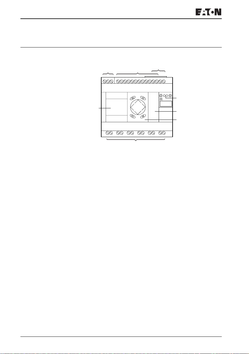
Device overview EZ basic units at a glance
ab
c
d
h
e
f
g
Figure 1: Device overview
Power supply
Inputs
EZ-NET connections
Operating status LEDs
Interface socket for memory card or PC connection
Buttons
Outputs
Display
For more information visit: www.EatonElectrical.com
MN05013004E14
Page 19
EZ800 type references
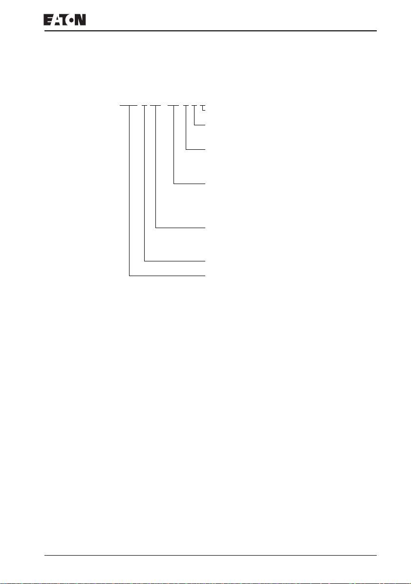
EZ x x x - x x - x x x
Device overview
LCD display: X = No display
Time switch: C = Available
Output type:
R = Relay
T = Transistor
Supply voltage, device and inputs
AC = AC voltage
DC = DC voltage
Number of inputs/outputs (+ expansion)
19 = 12 I/6 O + expansion
20 = 12 I/7 O + expansion
21 = 12 I/8 O + expansion
22 = 12 I/9 O + expansion
Performance class 8 (= 8 EZ-NET network stations)
EZ control relay
For more information visit: www.EatonElectrical.comMN05013004E 15
Page 20
EZ800 Control Relay
EZ operation Buttons
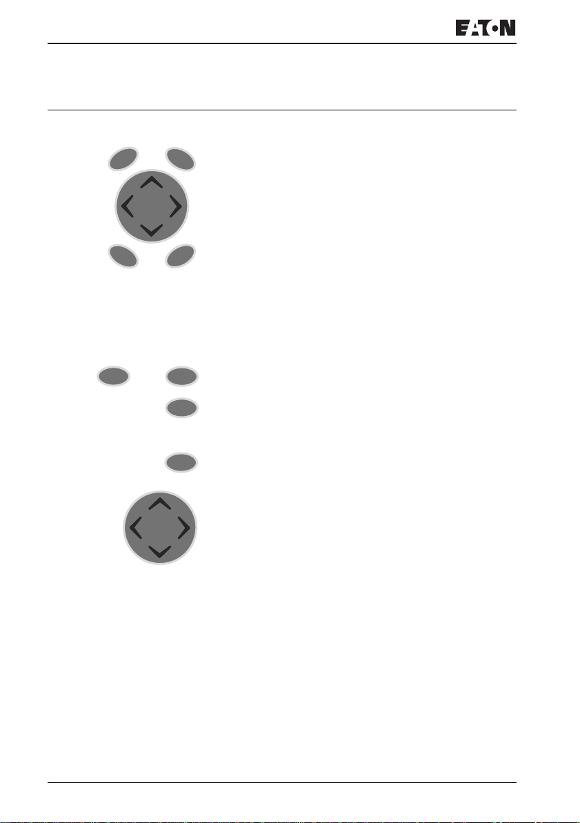
DEL: Delete object in circuit diagram
DEL
ESC
DEL
ALT
ALT: Special functions in circuit-diagram, Status display
Cursor buttons
Move cursor
Select menu items
Set contact numbers, contacts and values
OK
OK: Next menu level, Save your entry
ESC: Previous menu level, Cancel
Moving through menus and choosing values
and Show System menu
ALT
Go to next menu level
OK
Select menu item
Activate, modify, save your entry
Return to last menu level
ESC
Cancel your entry since the last OK
Í Ú
ú í
Function of P buttons:
ú
í
úíÍ Ú:
Change menu item
Change value
Change place
Input P1,
Input P3,
Í
Input P2
Ú
Input P4
For more information visit: www.EatonElectrical.com
MN05013004E16
Page 21
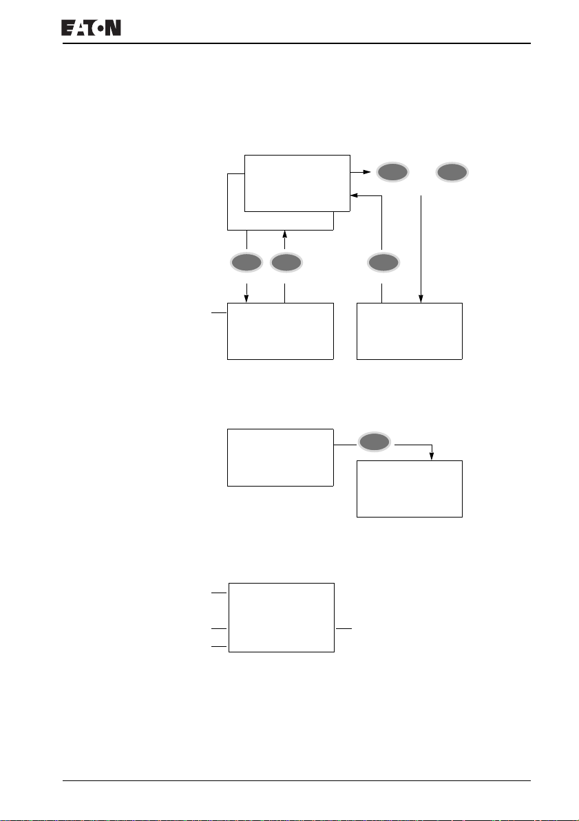
Selecting main and system menu
Status display
EZ operation
Current selection
flashes in
the EZ menu
I .2..5.......
R.2
MO 02:00
RS
Q..34 . STOP
MO
S .2 6..
OK
PROGRAM...
STOPå RUN
PARAMETERS
SET CLOCK
st
1
menu level
Main menu
P-
DEL
ESCESC
SECURITY...
SYSTEM...
MENU LANGUAGE
CONFIGURATOR...
1st menu level
System menu
Date display
I .2..5.......
P-
MO 11:50
Q..34.... STOP
ALT
I .2..5.......
MO 01.04.2002
Q..34.... STOP
EZ800 Control Relay status display
and
No
password
ALT
P-
Inputs
Weekday/Time or Weekday/Date
Outputs RUN/STOP/BUSY mode
I 12..........
PMO 02:00
Q..34.... STOP
On: 1, 2, 3, 4/Off:…
For more information visit: www.EatonElectrical.comMN05013004E 17
Page 22
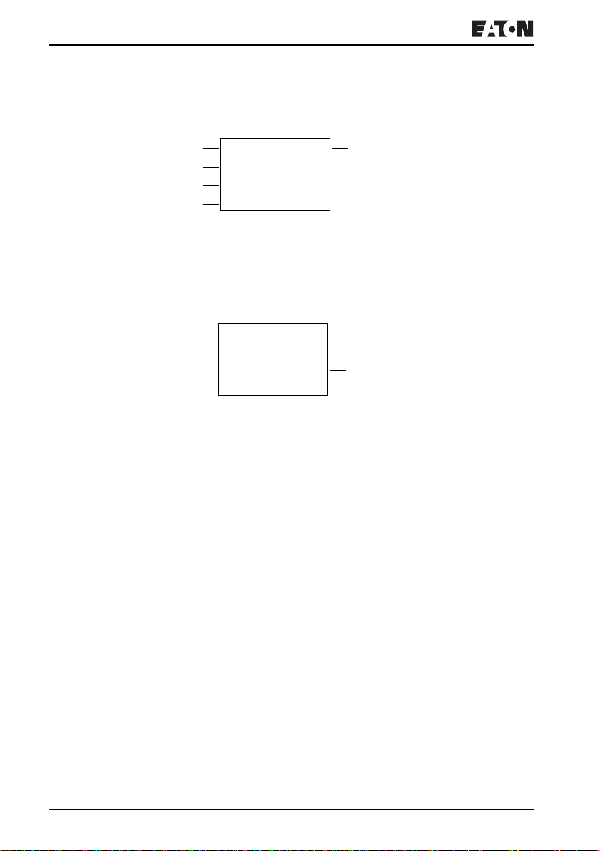
EZ800 Control Relay
Status display for local expansion
Inputs AC expansion ok/P buttons
Expansion or Weekday/Date
Weekday/Time
Outputs
R 1.........12
RS AC PMO 10:42
S 1......8 STOP
On: 1, 2, 3, 4/Off:…
RS = Expansion functioning correctly
EZ800 Control Relay advanced Status display
I 12...6.89..12
Retention/debounce/
EZ-NET station
: Retention switched on
RE
: Debounce switched on
I
: EZ-NET station with station address
NT1
: AC expansion functioning correctly
AC
: DC expansion functioning correctly
DC
: Bus coupling module detected
GW
GW flashes: Only EZ200-EZ detected. I/O expansion not be detected.
: When the power supply is switched on, EZ switches to STOP mode
ST
RE I NT1 AC PMO 14:42 T
Q 12345678 RUN
AC expansion ok/P buttons
Startup behavior
For more information visit: www.EatonElectrical.com
MN05013004E18
Page 23
EZ operation
EZ800 Control Relay LED display
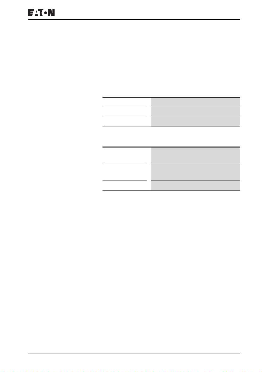
EZ800 Control Relay has two LEDs located on the front which
indicate the state of the power supply voltage (POW) as well
as the RUN or STOP modes (J Fig. 1, Page 14).
Table 1: LED power supply/RUN-STOP mode
LED OFF
LED continuously lit
LED flashing
Table 2: NET LED (EZ-NET)
LED OFF
LED continuously lit
LED flashing EZ-NET operating fault-free
No power supply
Power supply present, STOP mode
Power supply present, RUN mode
EZ-NET not operational, fault, in
configuration
EZ-NET is initialized and no station has
been detected.
For more information visit: www.EatonElectrical.comMN05013004E 19
Page 24
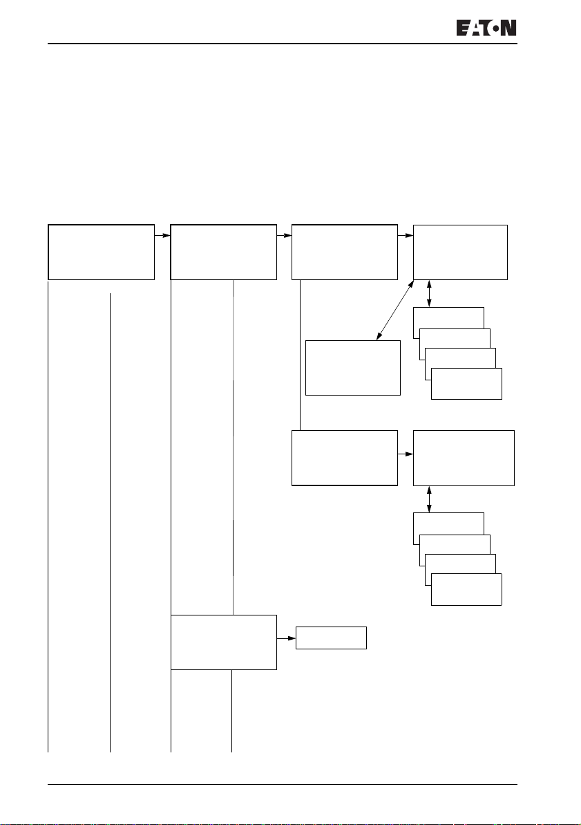
EZ800 Control Relay
Main menu
Menu structure
Main menu without password protection
XYou access the main menu by pressing OK.
STOP: Circuit diagram display
RUN: Power flow display
PROGRAM...
STOP å RUN
PARAMETERS
SET CLOCK
PROGRAM...
DELETE PROGRAM
CARD
PROGRAM...
DELETE PROGRAM
CARD...
CIRCUIT DIAGRAM
FUNCTION RELAYS
Parameter
display
Parameters
CIRCUIT DIAGRAM
FUNCTION RELAYS
DELETE ?
Circuit diagram
SAVE Æ
CANCEL Æ
SEARCH Æ
æ
GO TO Æ
æ
æ
æ
Function block editor
Parameters
SAVE Æ
CANCEL æ
SEARCH Æ
æ
GO TO Æ
æ
æ
æ
For more information visit: www.EatonElectrical.com
MN05013004E20
Page 25
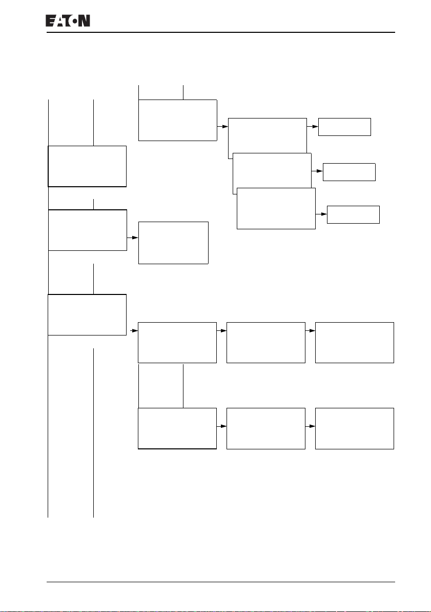
Main menu
PROGRAM...
STOP RUN å
PARAMETERS
SET CLOCK
PROGRAM...
STOP RUN å
PARAMETERS
SET CLOCK
PROGRAM...
DELETE PROGRAM
CARD...
Parameter display
Parameters
DEVICE-CARD
CARD-DEVICE
DELETE CARD ?
DEVICE-CARD
CARD-DEVICE
DELETE CARD ?
DEVICE-CARD
CARD-DEVICE
DELETE CARD ?
EZ operation
REPLACE ?
REPLACE ?
DELETE ?
PROGRAM...
STOP RUN å
PARAMETERS
SET CLOCK
Display for date and time
setting
SET CLOCK
DST SETTING
SET CLOCK
DST SETTING
HH:MM --:-DD.MM --.-YEAR ____
NONE å
MANUAL å
EU å
GB å
US å
HH:MM 14:23
DD.MM 03.10
YEAR 2001
SUMMERTIME START
DD.MM : --.-SUMMER TIME END
DD.MM : --.--
Only one selection is possible.
For more information visit: www.EatonElectrical.comMN05013004E 21
Page 26
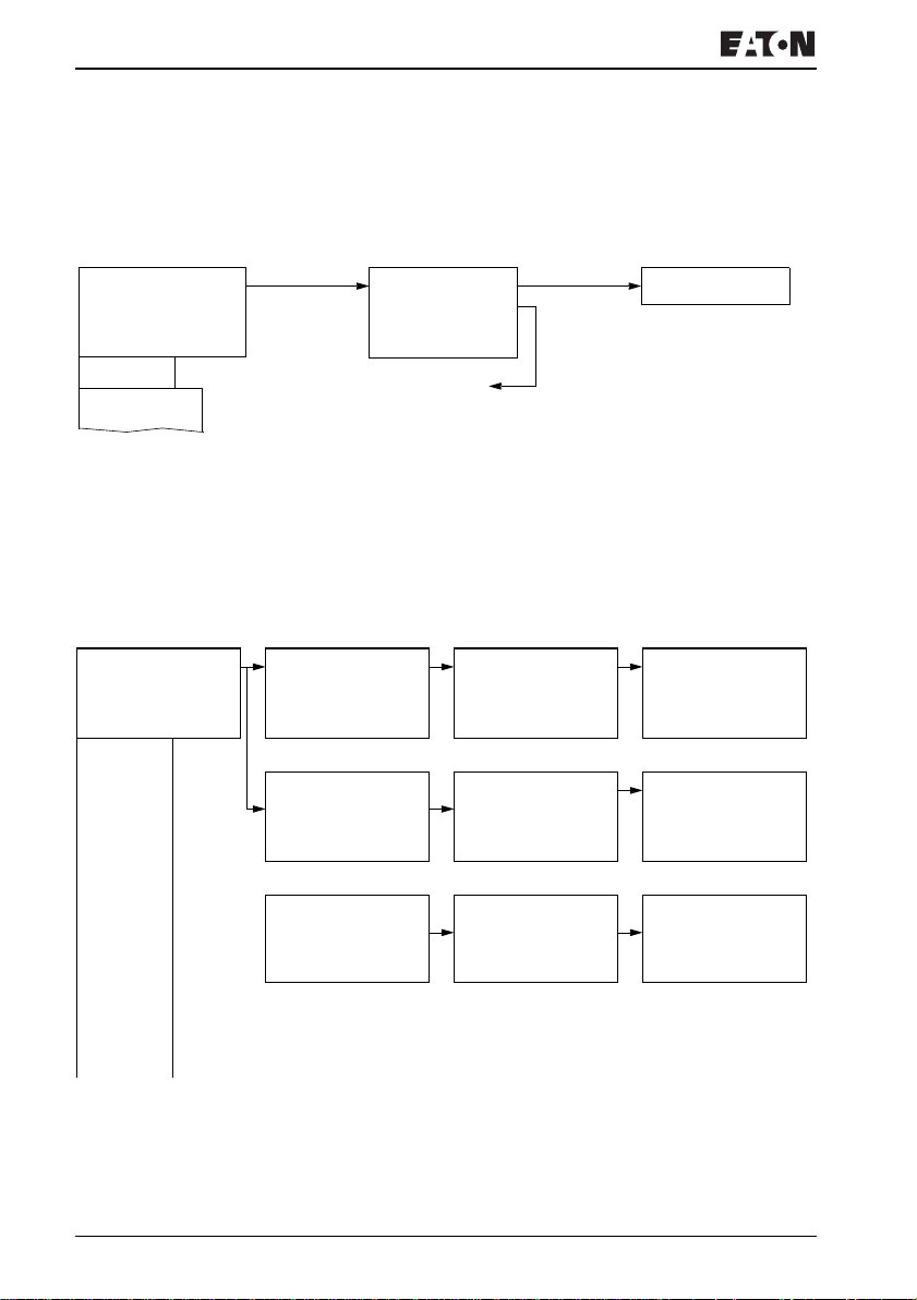
EZ800 Control Relay
Main menu with password protection
Main menu
PASSWORD...
STOP RUN å
PARAMETERS
SET CLOCK
PASSWORD...
RUN
System menu
SECURITY...
SYSTEM...
MENU LANGUAGE
CONFIGURATOR...
Password
change/
delete
Password
setup
PASSWORD...
RANGE...
ACTIVATE PW
CHANGE PW
Password entryUnlocking EZ
Password
(if enabled)
DELETE ALL?
Correct
Four wrong entries
Status display
entry
EZ800 Control Relay System menu
XThe System menu is accessed by simultaneously pressing
DEL and ALT.
Password entry
ENTER PASSWORD
------
ENTER PASSWORD
------
ACTIVATE PW
CHANGE PW
ACTIVATE PW
CHANGE PW
PASSWORD...
RANGE...
PROGRAM å Æ
PARAMETERS
TIME
OPERATING MODE æ
INTERFACE
DELETE FUNCTION
For more information visit: www.EatonElectrical.com
PROGRAM å Æ
PARAMETERS å
TIME å
OPERATING MODEåæ
INTERFACE å
DELETE FUNCTION
MN05013004E22
Page 27
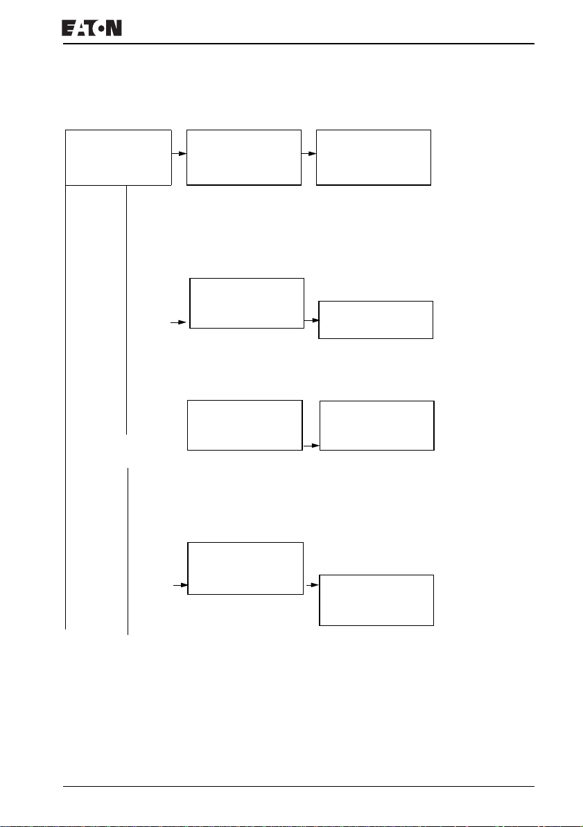
System menu
SECURITY...
SYSTEM...
MENU LANGUAGE
CONFIGURATOR...
Retention only in
STOP mode
DEBOUNCE å Æ
P BUTTONS
RUN MODE
CARD MODE æ
DISPLAY...
RETENTION...
INFORMATION...
DEBOUNCE å
P BUTTONS
RUN MODE
CARD MODE
DISPLAY... æ
RETENTION...
INFORMATION...
DEBOUNCE å
P BUTTONS
RUN MODE Æ
CARD MODE
DISPLAY...
RETENTION... æ
INFORMATION...
EZ operation
DEBOUNCE å Æ
P BUTTONS å
RUN MODE å
CARD MODE å æ
DISPLAY...
RETENTION...
INFORMATION...
Æ
CONTRAST: 0
LIGHTING å
MB -- -> MB -- Æ
C -- -> C -CH -- -> CH --
B: 200 æ
CI -- -> CI -DB -- -> DB -T -- -> T --
DEBOUNCE å
P BUTTONS
RUN MODE
CARD MODE Æ
DISPLAY...
RETENTION...
INFORMATION... æ
DC TCA LCD NET
OS : 1.10.201
CRC: 25808
For more information visit: www.EatonElectrical.comMN05013004E 23
Page 28
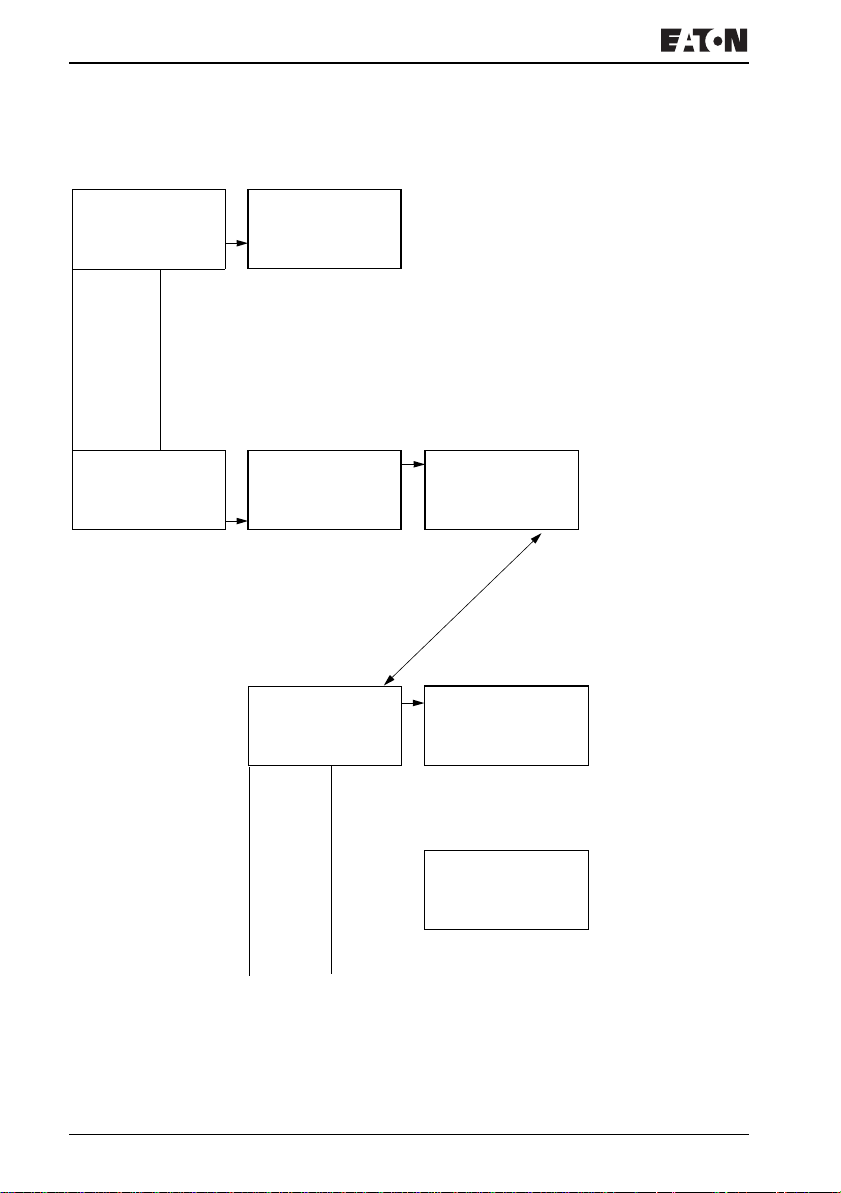
EZ800 Control Relay
System menu
SECURITY...
SYSTEM...
MENU LANGUAGE
CONFIGURATOR...
ENGLISH Æ
DEUTSCH å
FRANCAIS
ESPANOL æ
ITALIANO
PORTUGUES
NEDERLANDS
SVENSKA
POLSKI
TURKCE
Only one selection is possible.
SECURITY...
SYSTEM...
MENU LANGUAGE
CONFIGURATOR...
NET...
EZ-NET only in STOP
mode
NET PARAMETERS..
STATIONS...
CONFIGURE...
NET PARAMETERS..
STATIONS...
CONFIGURE...
NET-ID : __ Æ
BAUDRATE: ____KB
BUSDELAY: __
SEND IO: æ
REMOTE RUN
REMOTE IO
NET-ID : 01 Æ
BAUDRATE: 1000KB
BUSDELAY: 08
SEND IO: å æ
REMOTE RUN å
REMOTE IO å
For more information visit: www.EatonElectrical.com
MN05013004E24
Page 29
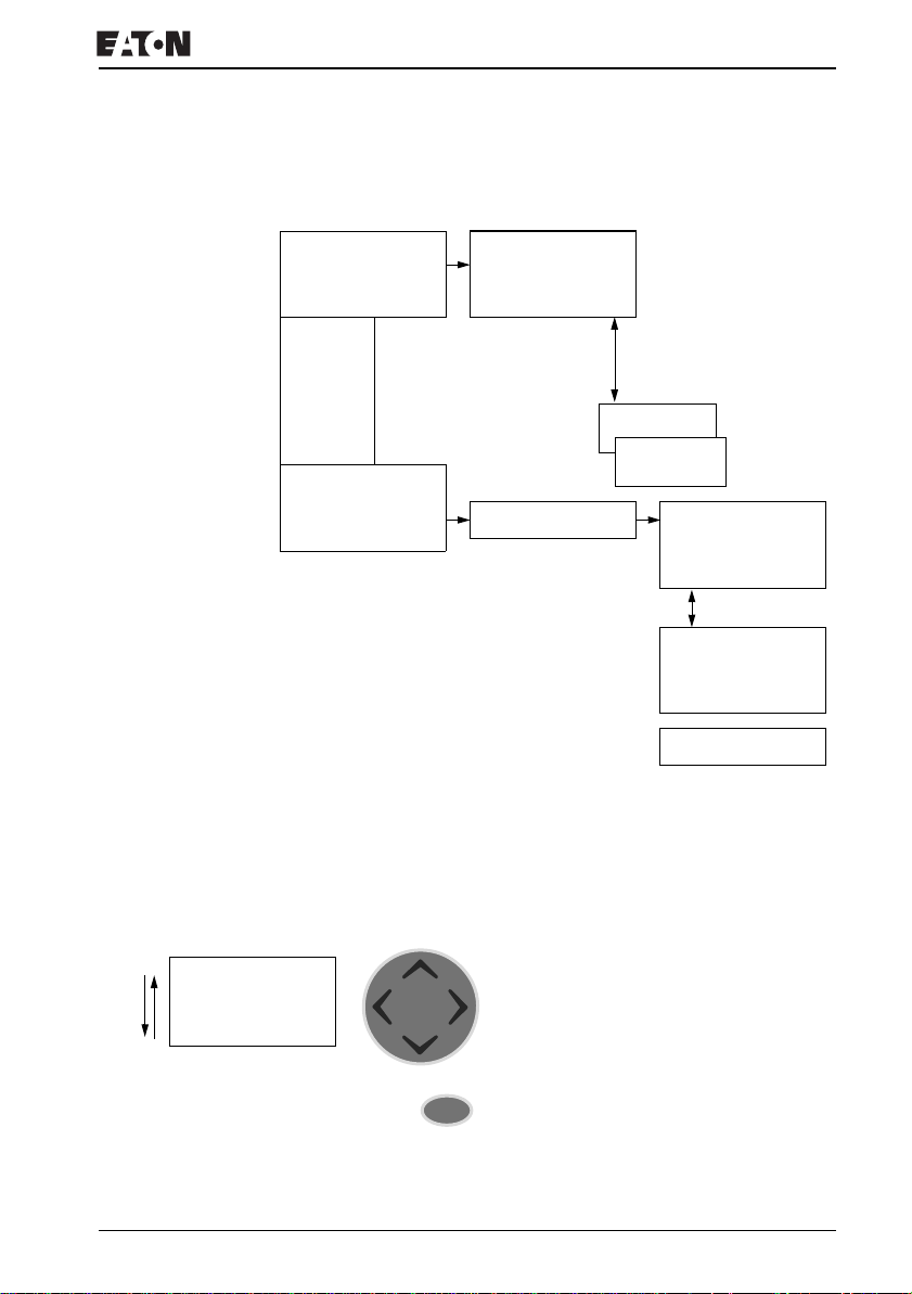
System menu
EZ operation
NET PARAMETERS..
STATIONS...
CONFIGURATOR...
NET PARAMETERS..
STATIONS...
CONFIGURATOR...
1 1 Æ
20
30
40 æ
50
60
70
80
SAVE Æ
CANCEL Æ
CONFIGURE?
Fault scenario
with ID conflict.
Fault scenario
with network fault.
This list is only created
in Station 1.
This list only appears if
station 1 has been
selected.
æ
æ
CONFIGURATION
IN
PROGRESS.
ERR: ID-CONFLICT
CONFIGURATION
OVERWRITE?
ERR: TIME OUT
PROGRAM...
STOP
PARAMETERS
SET CLOCK
Selecting or toggling between menu items
Cursor Í Ú
Select or toggle
OK
For more information visit: www.EatonElectrical.comMN05013004E 25
Page 30
EZ800 Control Relay
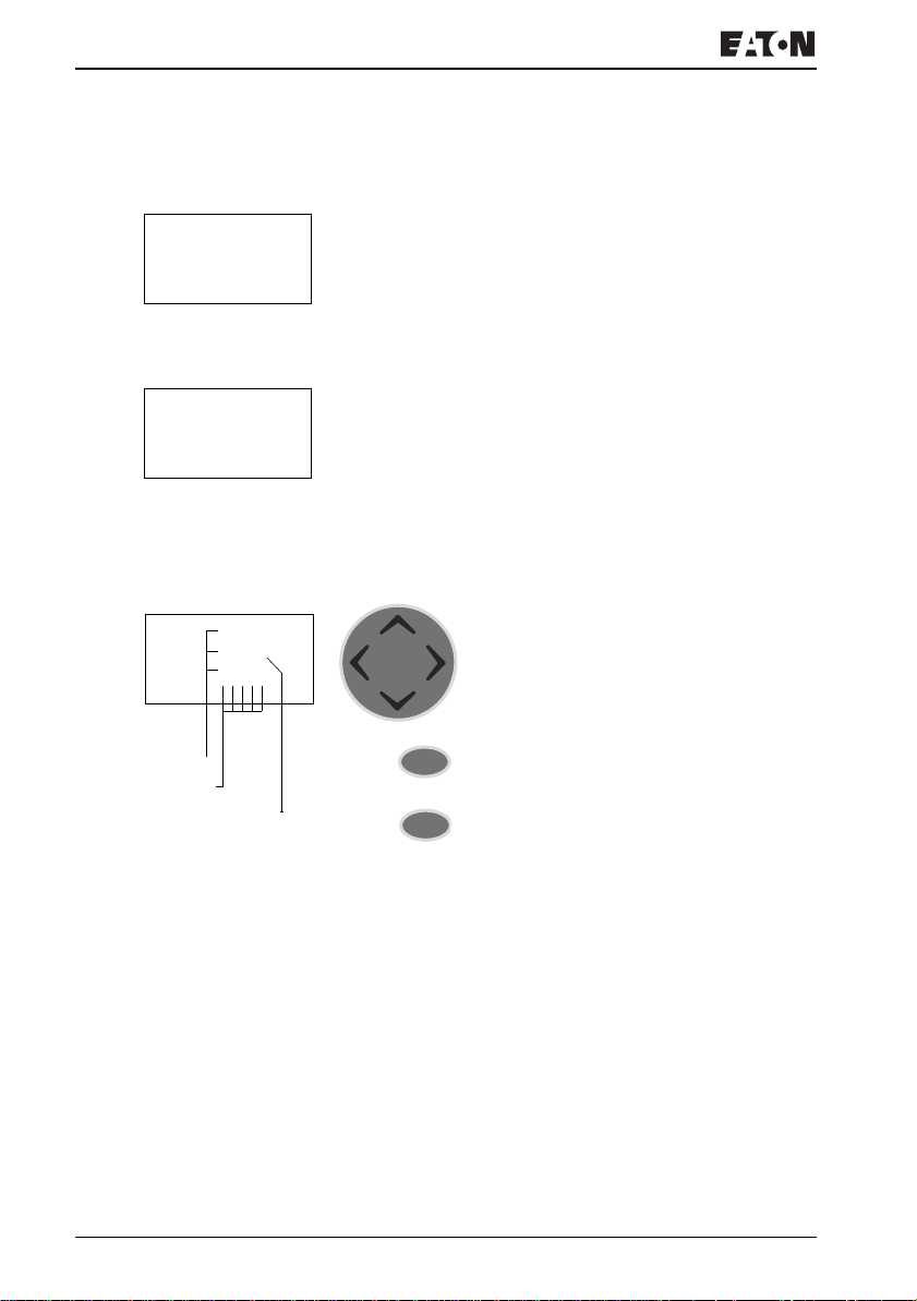
Cursor display
HH:MM '4:23
DD.MM 05.05
YEAR 2003
HH:MM 14:23
DD.MM 05.05
YEAR 2003
HH:MM 14:23
DD.MM 03.10
YEAR 2002
Values
Positions
Value at position
The cursor flashes:
Full cursor
• Move cursor with
• in circuit diagram also with
Ê/:
ú í,
Í Ú
Value M/ M
• Change position with ú í
• Change values with Í Ú
Flashing values/menus are shown in gray in this manual.
Setting values
Change value Í Ú
Select cursor position in value ú í
Change value at position Í Ú
Store entries
OK
Retain previous value
ESC
For more information visit: www.EatonElectrical.com
MN05013004E26
Page 31
2Installation
The EZ must only be installed and wired up by qualified
electricians or other persons familiar with the installation of
electrical equipment.
Danger of electric shock!
Never carry out electrical work on the device while the
power supply is switched on.
Always follow the safety rules:
• Switch off and isolate,
• Ensure that the device is no longer live,
• Short-circuit and ground,
• Cover adjacent live parts.
The EZ is installed in the following order:
• Mounting,
• Wiring up the inputs,
• Wiring up the outputs,
• Wiring up the NET network (if required),
• Connecting the power supply.
Mounting Install EZ in an enclosure, switch cabinet or distribution board
so that the power feed and terminal connections cannot be
touched accidentally during operation.
Snap EZ onto a IEC/EN 60715 top-hat rail or fix EZ in place
using fixing brackets. EZ can be mounted vertically or
horizontally.
J
For more information visit: www.EatonElectrical.com 27MN05013004E
When using the EZ with expansion units, connect the
expansion concerned before mounting (see
J page 30).
Page 32
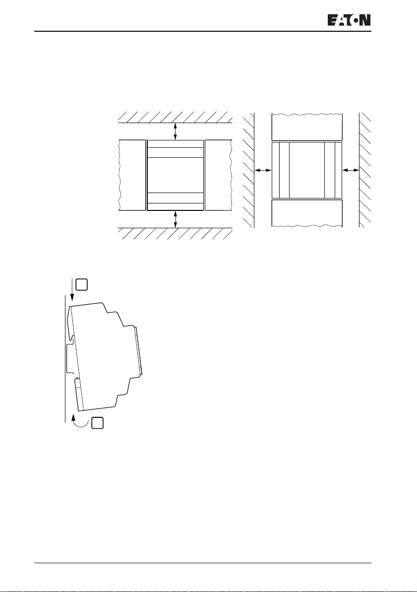
Installation
For ease of wiring, leave a gap of at least 30 mm between the
EZ terminals and the wall or adjacent devices.
30
30
Figure 2: Clearances to the EZ
. Mounting on mounting rail
1
XHook the EZ to the top edge of the top-hat rail and hinge
into place while pressing down slightly. Press down lightly
on both the device and the top-hat rail until EZ snaps over
the lower edge of the top-hat rail.
The EZ will clip into place automatically.
XCheck that EZ is seated firmly.
EZ is mounted vertically on a top-hat rail in the same way.
2
30
30
For more information visit: www.EatonElectrical.com
MN05013004E28
Page 33
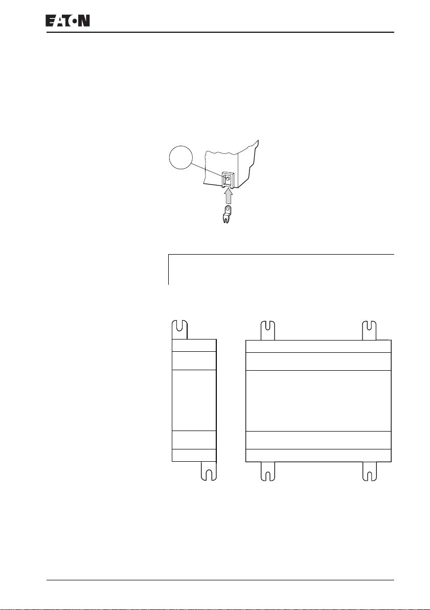
Mounting
Screw mounting
For screw mounting on a mounting plate, fixing brackets must
be used that can be fixed to the back of the EZ. The fixing
brackets can be ordered as an accessory.
CLICK !
Figure 3: Inserting a fixing bracket
-
J
Three fixing brackets are sufficient for a device with four
fixing points.
EZ2..-..: EZ700, EZ800 Control Relay:
Figure 4: Screw mounting for EZ
For more information visit: www.EatonElectrical.comMN05013004E 29
Page 34
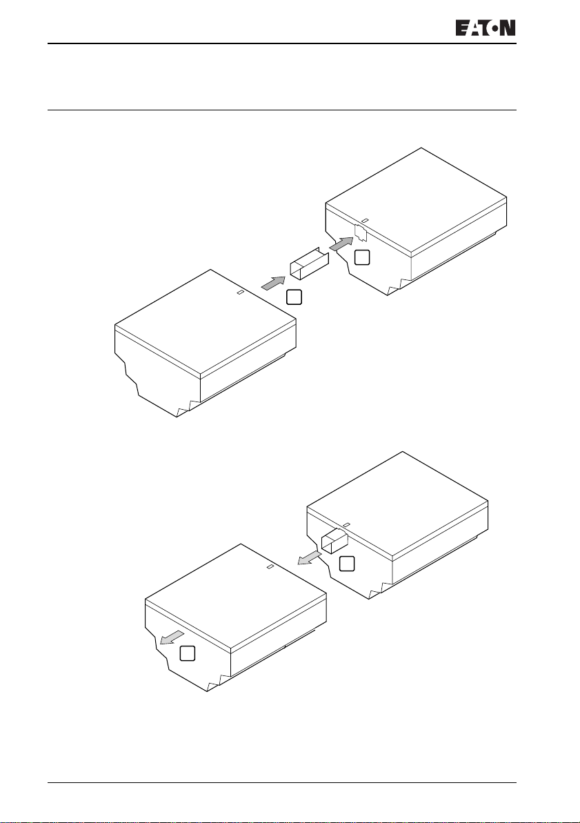
Installation
Connecting the expansion device
1
2
4
3
Figure 5: Expansion connection
For more information visit: www.EatonElectrical.com
MN05013004E30
Page 35

Terminals
Terminals Tools
Slot-head screwdriver, width 3.5 mm, tightening torque
0.6 Nm (0.4 Ftlbs).
Cable cross-sections
• Solid: 0.2 to 4 mm
• Flexible with ferrule: 0.2 to 2.5 mm
Network cables and plug Use the prefabricated EZ-NT-“Length” cables when possible.
AWG 24, 0.2 mm
The first and last stations in the network must each be
terminated with the EZ-NT-R bus termination resistor.
2
(AWG 22 - -12)
2
(AWG 22 -12)
2
are the largest crimpable cross-sections.
Connecting the power supply
J
For more information visit: www.EatonElectrical.comMN05013004E 31
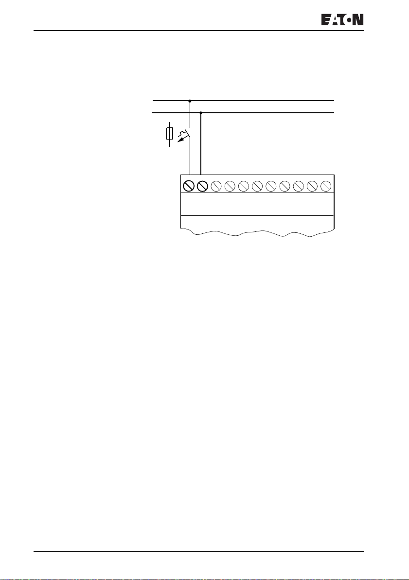
For the connection data of both versions, EZ-DC with 24 V
DC and EZ-AC with standard voltages of 100 V to 240 V
AC, refer to Chapter “Technical data” from Page 314.
The EZ800 Control Relay devices run a system test for one
second after the power supply has been switched on. Either
RUN or STOP mode will be activated after this time
depending on the default setting.
Page 36
Installation
AC basic units
L
N
F1
NNL
115/230 V
Figure 6: Power supply on the AC-basic units
~
For more information visit: www.EatonElectrical.com
MN05013004E32
Page 37
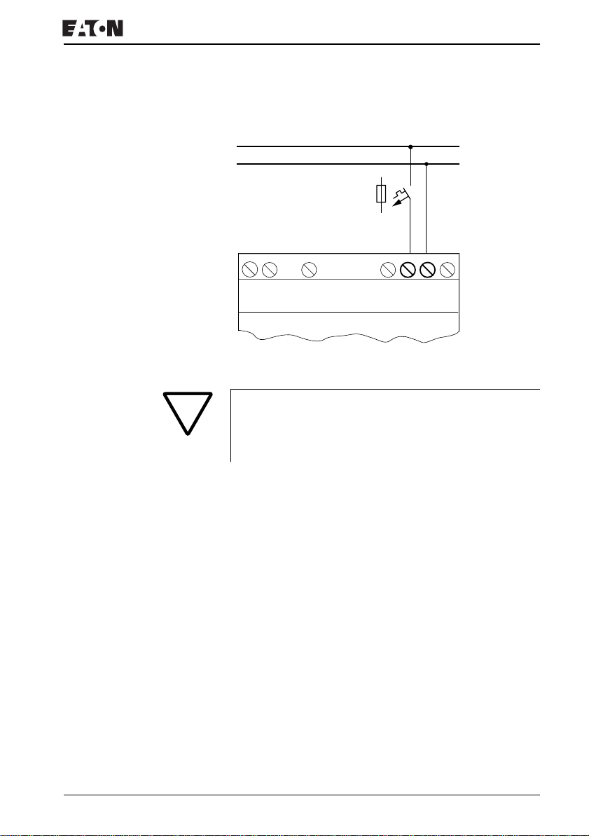
Connecting the power supply
EZ…-AC-.E expansion units
L
N
F1
E+
R1
E-
...
R12
115/230 V
NNL
~
Figure 7: Power supply on the AC expansion units
Attention!
A short current surge will be produced when switching on
for the first time. Do not switch on EZ AC via Reed contacts
since these may burn or melt.
For more information visit: www.EatonElectrical.comMN05013004E 33
Page 38
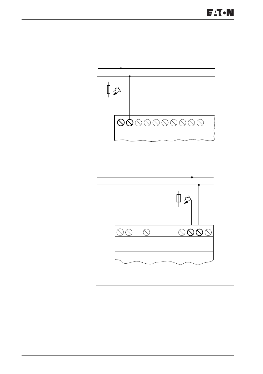
Installation
DC basic units
+
L01
L01 –
F1
...V
DC : +24 V
0 V0 V
I1
I4
I3I2
Figure 8: Power supply on the DC basic units
EZ…-DC-.E DC expansion units
L01+
L01-
...
I7
I6I5
F1
R1
E+
E-
...
Figure 9: Power supply on the DC expansion units
EZ DC is protected against polarity reversal. To ensure that
J
EZ works correctly, ensure that the polarity of each terminal
is correct.
For more information visit: www.EatonElectrical.com
R12
0V0V24V
24 V
MN05013004E34
Page 39
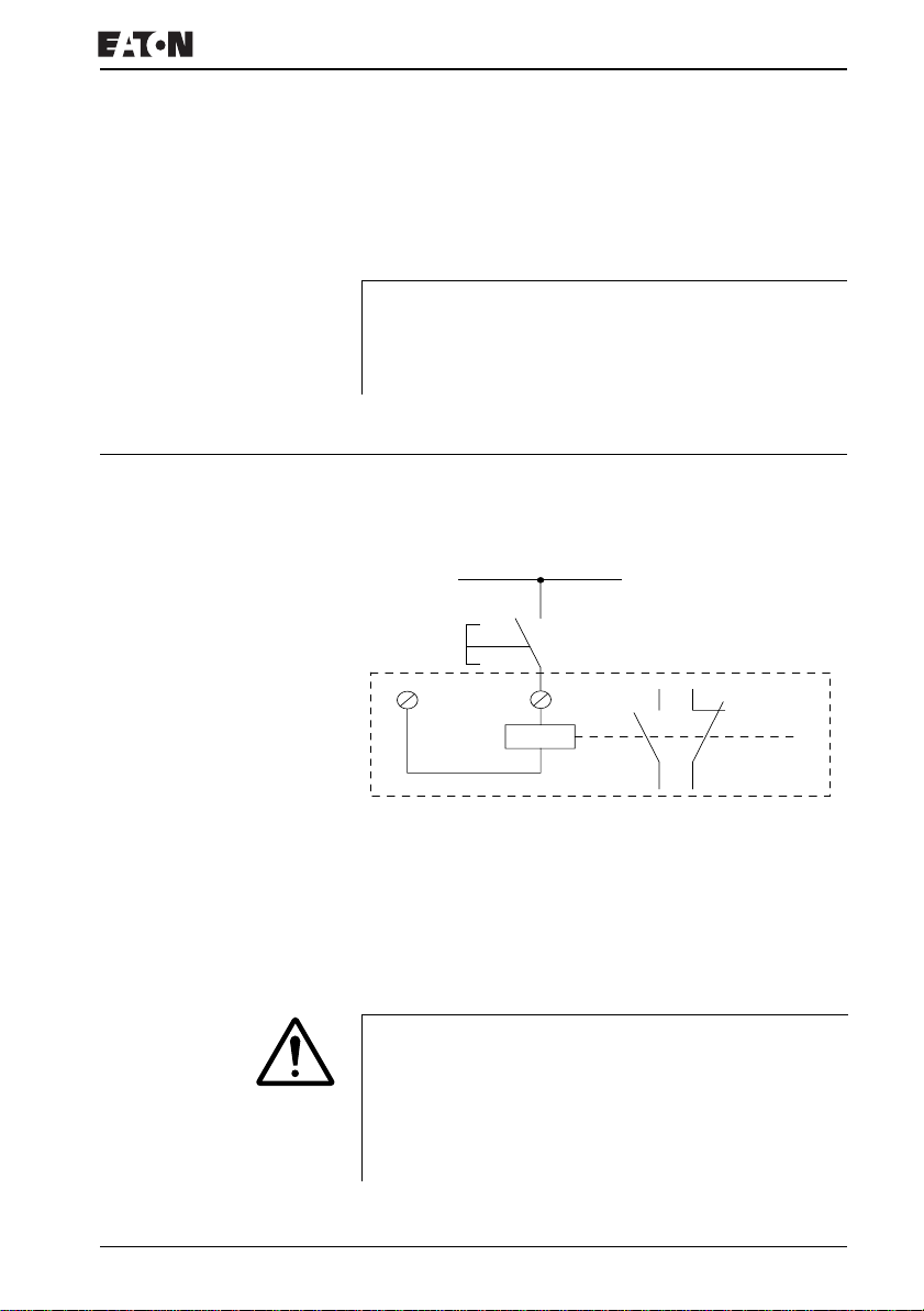
Connecting the inputs
Cable protection
Both EZ AC and DC versions require cable protection (F1)
rated for at least 1 A (slow).
J
circuit behaves like a capacitor. Use an appropriate device
for switching on the power supply and do not use any reed
relay contacts or proximity switches.
Connecting the inputs EZ inputs switch electronically. Once you have connected a
contact via an input terminal, you can reuse it as a contact in
your EZ circuit diagram as often as you like.
When EZ is switched on for the first time, its power supply
L
+24 V
S1
N
0 V
Figure 10: Connecting the inputs
I1
I1 i1
Connect contacts such as pushbutton actuators or switches to
EZ input terminals.
Connecting the AC inputs
Caution!
For EZ-AC, connect the inputs to the same line as the
power feed in accordance with the VDE, IEC, UL and CSA
safety regulations. Otherwise EZ will not detect the
switching level and may be damaged or destroyed by
overvoltage.
For more information visit: www.EatonElectrical.comMN05013004E 35
Page 40
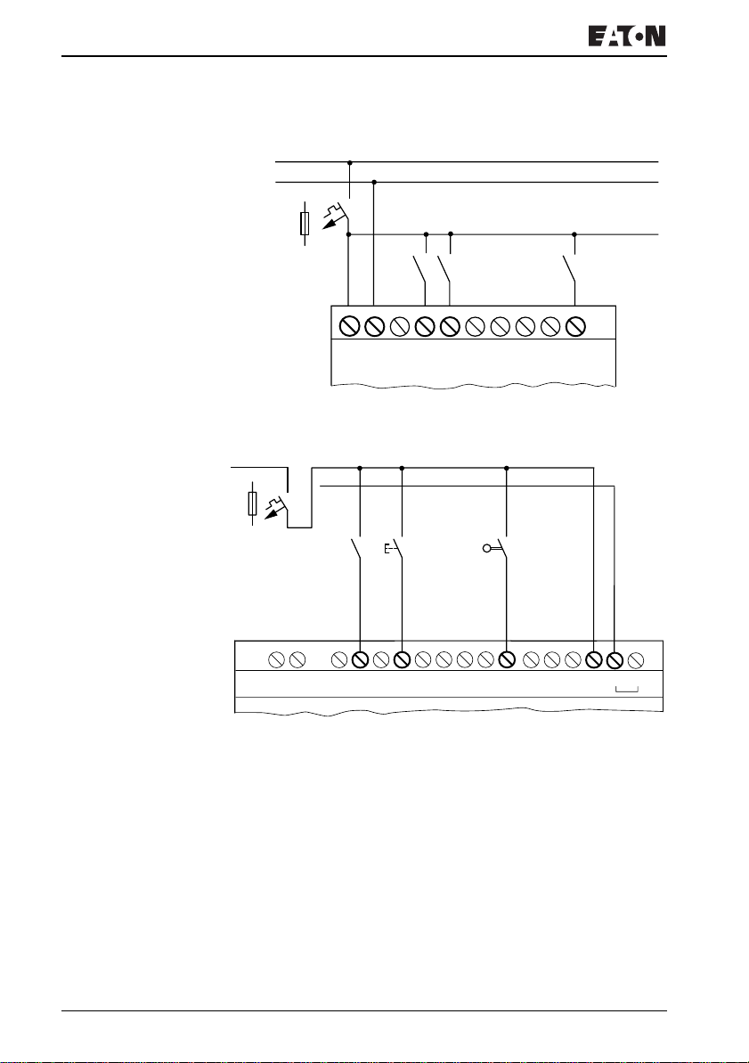
Installation
L
N
F1
LNN
115/230 V h
Figure 11: EZ-AC basic unit
L1
N
F1
l3 I4 l5 I6
l1 I2 I7
...
R10R9R8R7R6R5R4R3R2R1E+ E–
115/230 V h
Figure 12: Inputs on the EZ…-AC-.E expansion device
Connect the inputs, for example, to pushbutton actuators,
switches or relay/contactor contacts.
Input signal voltage range
• OFF signal: 0 V to 40 V
• ON signal: 79 V to 264 V
For more information visit: www.EatonElectrical.com
R11
R12 NNL
MN05013004E36
Page 41
Connecting the inputs
Input current
• R1 to R12, I1 to I6, I9 to I12:
0.5 mA/0.25 mA at 230 V/115 V
• I7, I8: 6 mA/4 mA at 230 V/115 V
Cable length
Severe interference can cause the input of a signal condition
“1” without a proper signal being applied. Observe therefore
the following maximum cable lengths:
• R1 to R12: 40 m without additional circuit
• I1 to I6, I9 to I12: 100 m with input debounce switched on,
60 m without additional circuit with input debounce
switched off.
• I7, I8: 100 m without additional circuit
The following applies to expansion units:
With longer cables, connect a diode (e.g. 1N4007) for 1 A,
minimum 1 000 V reverse voltage, in series to the EZ input.
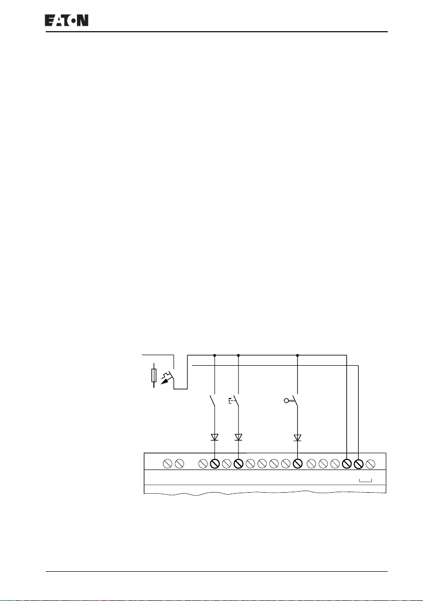
Ensure that the diode is pointing towards the input as shown
in the circuit diagram, otherwise EZ will not detect the 1 state.
L1
N
F1
R10R9R8R7R6R5R4R3R2R1E+ E–
R11
R12 NNL
115/230 V h
Figure 13: EZ-AC with a diode on the inputs
For more information visit: www.EatonElectrical.comMN05013004E 37
Page 42
Installation
Neon bulbs with a maximum residual current of 2 mA /1 mA at
230 V/115 V can be connected to I7 and I8.
J
connection.
Caution!
Do not use reed relay contacts on I7, I8. These may burn or
melt due to the high inrush current of I7, I8.
Two-wire proximity switches have a residual current with the
“0” state. If this residual current is too high, the EZ input may
detect a “1” signal.
Therefore, use inputs I7 and I8. An additional input circuit is
required if more inputs are used.
Increasing the input current
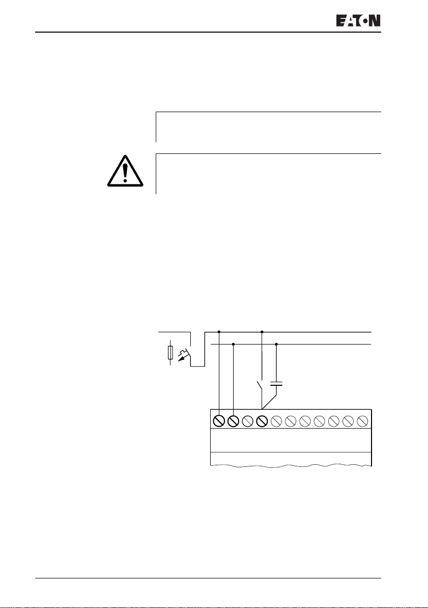
The following input circuit can be used in order to prevent
interference and also when using two-wire proximity switches:
L
N
F1
100 nF/275 V h
Always use neon bulbs that are operated with a separate N
LN
115/230 V h
Figure 14: Increasing the input current
For more information visit: www.EatonElectrical.com
I1
MN05013004E38
Page 43
Connecting the inputs
L
N
J
increases by 80 (66.6) ms at 50 (60) Hz.
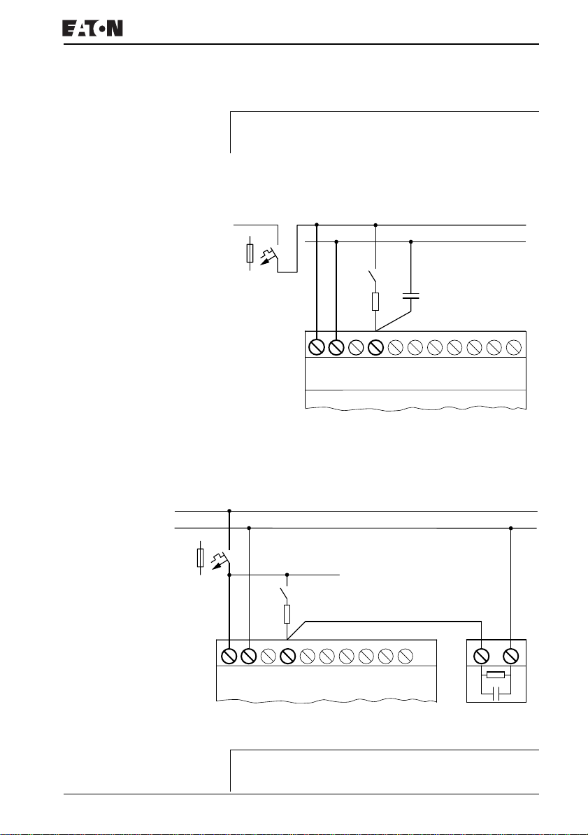
A resistor can be connected in series with the circuit shown in
order to restrict the inrush current.
When using a 100 nF capacitor the drop-off time of the input
L
N
F1
100 nF/275 V h
1 kO
LN I1
115/230 V h
Figure 15: Limitation of the inrush current with a resistor
Complete devices for increasing the input current are
available under the type reference EZ256-HCI.
F1
1 kO
...
LNN
115/230 V h
I2 I3 I4 I5
I1
I6 I7
Figure 16: EZ800 Control Relay with EZ256-HCI
The increased capacitance increases the drop-out time by
J
For more information visit: www.EatonElectrical.comMN05013004E 39
approx. 40 ms.
Page 44
Installation
Connecting the EZ-DC
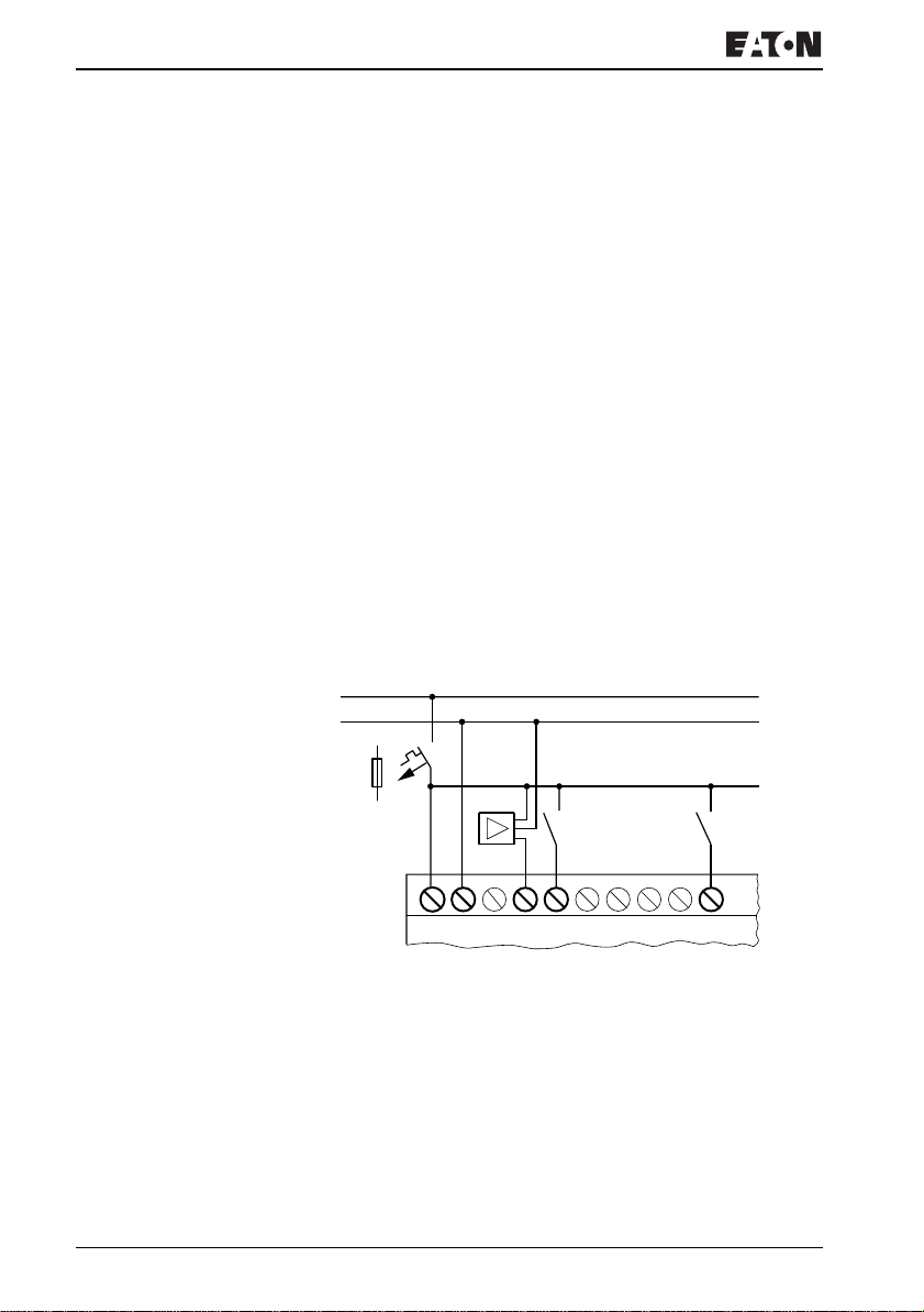
Use input terminals I1 to I12 to connect pushbutton actuators,
switches or 3 or 4-wire proximity switches. Given the high
residual current, do not use 2-wire proximity switches.
Input signal voltage range
• I1 to I6, I9, I10
– OFF signal: 0 to 5
– ON signal: 15 V to 28.8 V
• I7, I8, I11, I12
– OFF signal: < 8 V
– ON signal: > 8 V
Input current
• I1 to I6, I9, I10, R1 to R12: 3.3 mA at 24 V
• I7, I8, I11, I12: 2.2 mA at 24 V
L01⫹
L01⫺
F1
0 V
0 V l1 I2 I7
...V
l3 I4
Figure 17: EZ-DC
For more information visit: www.EatonElectrical.com
...
l5 I6
MN05013004E40
Page 45
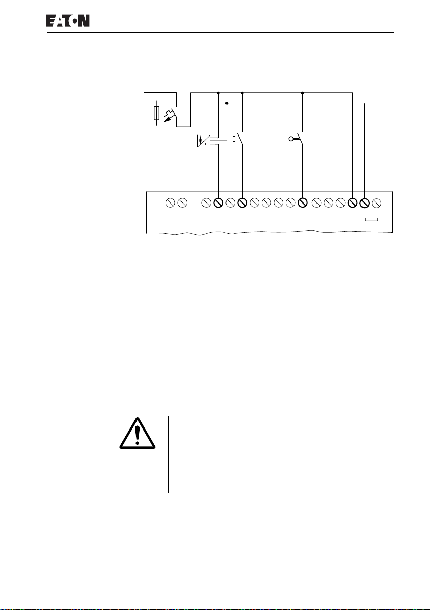
Connecting the inputs
L01 +
L01 –
F1
R10R9R8R7R6R5R4R3R2R1E+ E–
R11
R12 0V0V+24V
24 V H
Figure 18: EZ…-DC-.E
Connecting analog inputs
Inputs I7, I8, I11 and I12 can also be used to connect analog
voltages ranging from 0 V to 10 V.
The following applies:
• I7 = IA01
• I8 = IA02
• I11 = IA03
• I12 = IA04
The resolution is 10-bit = 0 to 1023.
Caution!
Analog signals are more sensitive to interference than
digital signals. Consequently, more care must be taken
when laying and connecting the signal lines. Incorrect
switching states may occur if they are not connected
correctly.
XUse shielded twisted pair cables to prevent interference
with the analog signals.
XFor short cable lengths, ground the shield at both ends
using a large contact area. If the cable length exceeds 30 m
or so, grounding at both ends can result in equalization
currents between the two grounding points and thus in the
For more information visit: www.EatonElectrical.comMN05013004E 41
Page 46
Installation
interference of analog signals. In this case, only ground the
cable at one end.
XDo not lay signal lines parallel to power cables.
XConnect inductive loads to be switched via the EZ outputs
to a separate power feed, or use a suppressor circuit for
motors and valves. If loads such as motors, solenoid valves
or contactors are operated with EZ via the same power
feed, switching may give rise to interference on the analog
input signals.
The following circuits contain examples of applications for
analog value processing.
J
the 0 V of the power supply unit for the different setpoint
potentiometers and sensors shown in the examples to the
0 V terminal of the EZ power feed.
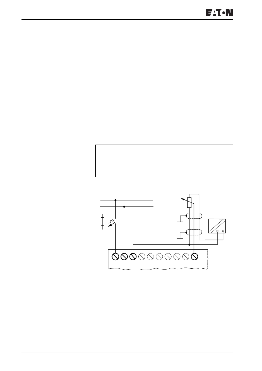
Setpoint potentiometer
Ensure that the reference potential is connected. Connect
L01⫹
L01⫺
F1
0 V0 V
Figure 19: Setpoint potentiometer
I4I3
I2I1
Use a potentiometer with a resistance of 1kΩ, e.g.
1kΩ,0.25W.
h
H
0 V
+12 V
...
I6I5
I724 V
For more information visit: www.EatonElectrical.com
MN05013004E42
Page 47
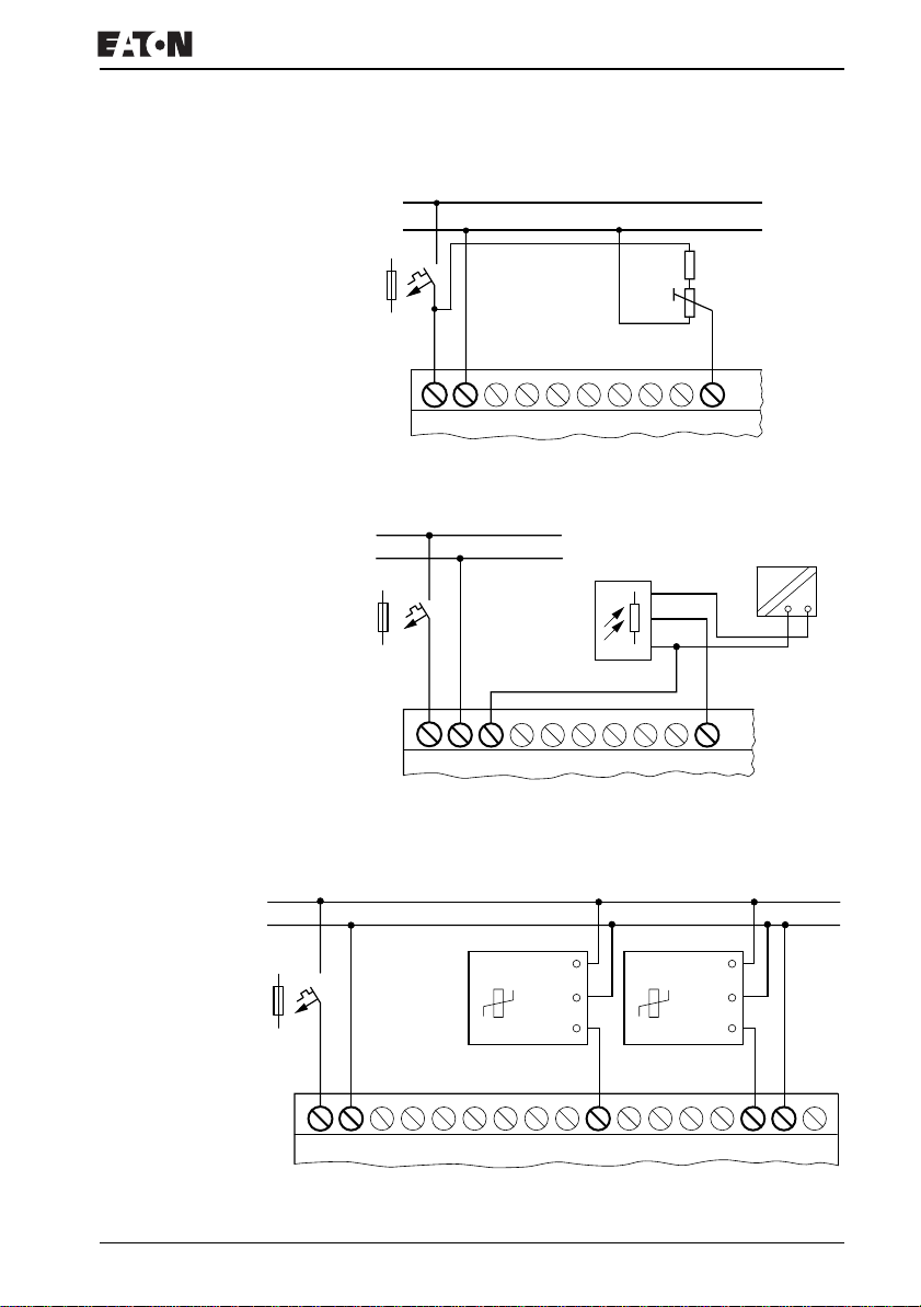
L01⫹
L01⫺
Connecting the inputs
L01⫹
L01⫺
F1
1.3 kO/0.25 W
1 kO/0.25 W
...
I1
0 V 0 V I7
24 V
I2
I3 I5
I4
I6
Figure 20: Setpoint potentiometer with upstream resistor
L01⫹
L01⫺
12 V
F1
0...10 V
0 V
...
I6I5
0 V0 V
I4I3
I2I1
I724 V
Figure 21: Brightness sensor
Temperature sensor
h
H
0 V
+12 V
–35...55 ˚C
+24 V H
Out
0...10 V
0 V
+24 V H
F1
–35...55 ˚C
0 V
Out
0...10 V
I724 V 0 V
I60 V I2I1 I4I3 I5 I8 I10I9 I12I11 0 V –
Figure 22: Temperature sensor
For more information visit: www.EatonElectrical.comMN05013004E 43
Page 48
Installation
20 A sensor
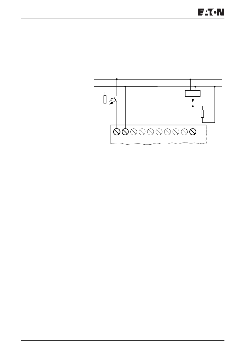
4 to 20 mA (0 to 20 mA) sensors can be connected easily
without any problem using an external 500 Ω resistor.
L01⫹
L01⫺
F1
a
4...20 mA
500 O
...
I724 V 0 V0 V I2I1 I4I3 I6I5
Figure 23: 20 A sensor
Analog sensor
The following values apply:
• 4 mA = 1.9 V
• 10 mA = 4.8 V
• 20 mA = 9.5 V
(according to U = R × I = 478 Ω ×10 mA ~ 4.8 V)
For more information visit: www.EatonElectrical.com
MN05013004E44
Page 49
Connecting the inputs
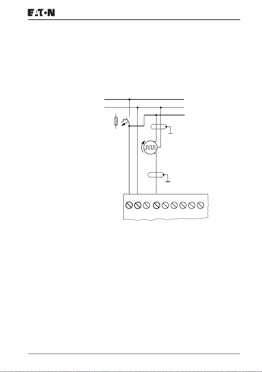
Connecting high-speed counters and frequency
generators
High-speed counter signals on the EZ800 Control Relay can
be counted correctly on inputs I1 to I4 independently of the
cycle time.
L01 +
L01 –
L02 +
F1
...V
24 V H
0 V
0 V
I1
I2 I3
I4 I5
I6
Figure 24: High-speed counter, frequency generator
For more information visit: www.EatonElectrical.comMN05013004E 45
Page 50
Installation
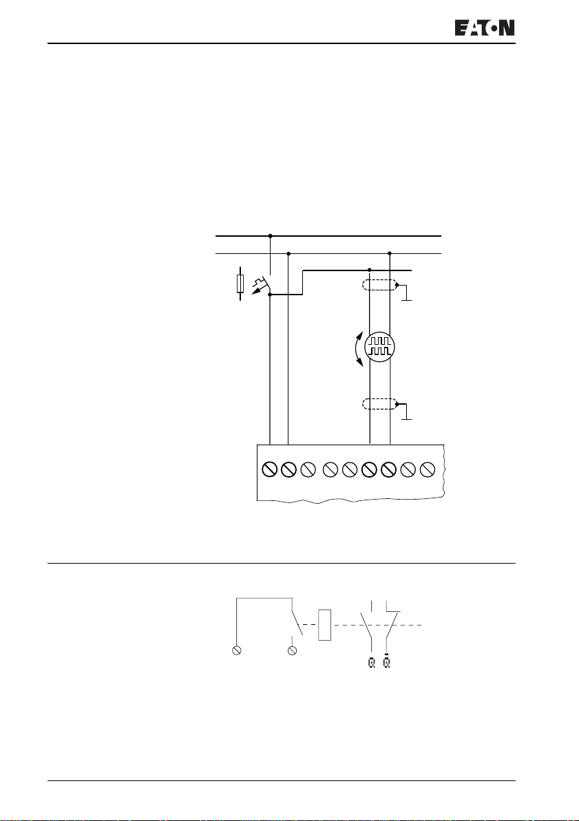
Connecting incremental encoders
Inputs I1, I2 and I3, I4 on the EZ800 Control Relay can each
be used for the high-speed counting of an incremental
encoder independently of the cycle time. The incremental
encoder must generate two 24 V DC square wave signals
with a 90° phase shift between them.
L01 +
L01 –
L02 +
F1
AB
...V
24 V H
0 V
0 V
I1
I2 I3
I4 I5
I6
Figure 25: Connecting incremental encoders
Connecting the outputs The Q... outputs function inside EZ as isolated contacts.
Q1
12
Figure 26: Output “Q”
For more information visit: www.EatonElectrical.com
MN05013004E46
Page 51
The respective relay coils are actuated in the EZ circuit
diagram via the output relays Q 01 to Q 06 or Q 08 to Q . You
can use the signal states of the output relays as make or break
contacts in the EZ circuit diagram for additional switching
conditions.
The relay or transistor outputs are used to switch loads such
as fluorescent tubes, filament bulbs, contactors, relays or
motors. Check the technical thresholds and output data
before installing such devices (see a chapter “Technical data”,
from Page 309).
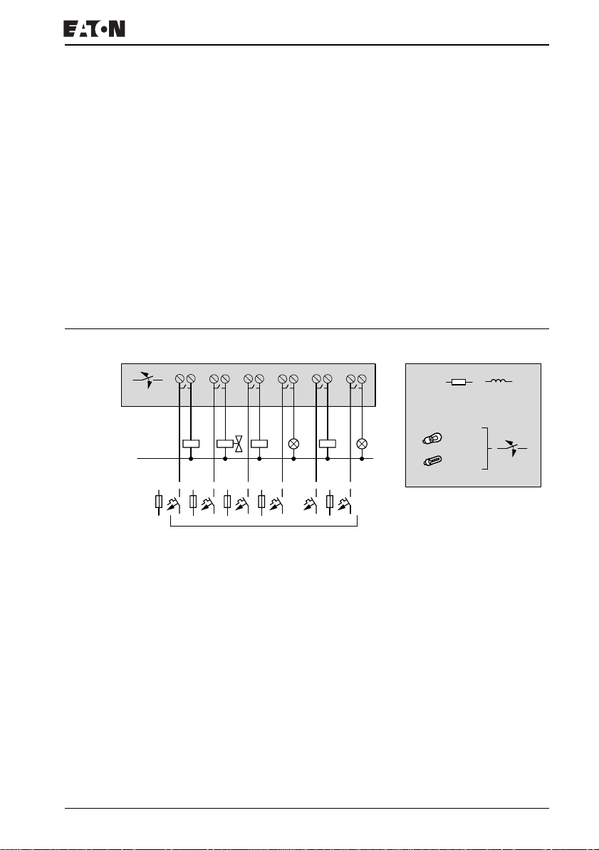
Connecting relay outputs EZ8..-..-RC.
Connecting relay outputs
10 000 000
0 V H, N
F
8 A/B 16
L1, L2, L3 (115/230 V h)
+ 24 V H
12 2 2 2 2 2
Q1
Q2
1
1
1
1
Q6Q5Q4Q3
Figure 27: EZ8..-..RC. relay outputs
1
R
24 V H 8 A
115 V h 8 A
230 V h 8 A
1000 W
10 x 58 W
2A
2A
2A
25 000
For more information visit: www.EatonElectrical.comMN05013004E 47
Page 52
Installation
EZ6..-..-RE
10 000 000
0 V H, N
F
8 A/B 16
L1, L2, L3 (115/230 V h)
+ 24 V H
12 2 2 2 2 2
S1
S2
1
1
1
1
S6S5S4S3
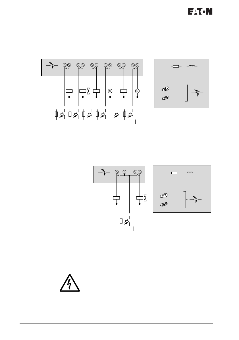
Figure 28: EZ6..-..-RE relay outputs
EZ2..-RE
12 2
S1
10 000 000
0 V H, N
F
8 A/B 16
L1, L2, L3 (115/230 Vh)
+ 24 V
HV
1
1
S2
R
8A
24 V H
115 V h 8A
230 V h 8 A
1000 W
10 x 58 W
R
H
24 V
8A
115 V h 8A
230 V h 8 A
1000 W
10 x 58 W
2A
2A
2A
2A
2A
2A
25 000
25 000
Figure 29: EZ2..-RE relay outputs
Unlike the inputs, the EZD-R.., EZ6..-..-RE relay outputs can
be connected to different lines.
Do not exceed the maximum voltage of 250 V AC on a relay
contact. If the voltage exceeds this threshold, flashover may
occur at the contact, resulting in damage to the device or a
connected load.
For more information visit: www.EatonElectrical.com
MN05013004E48
Page 53
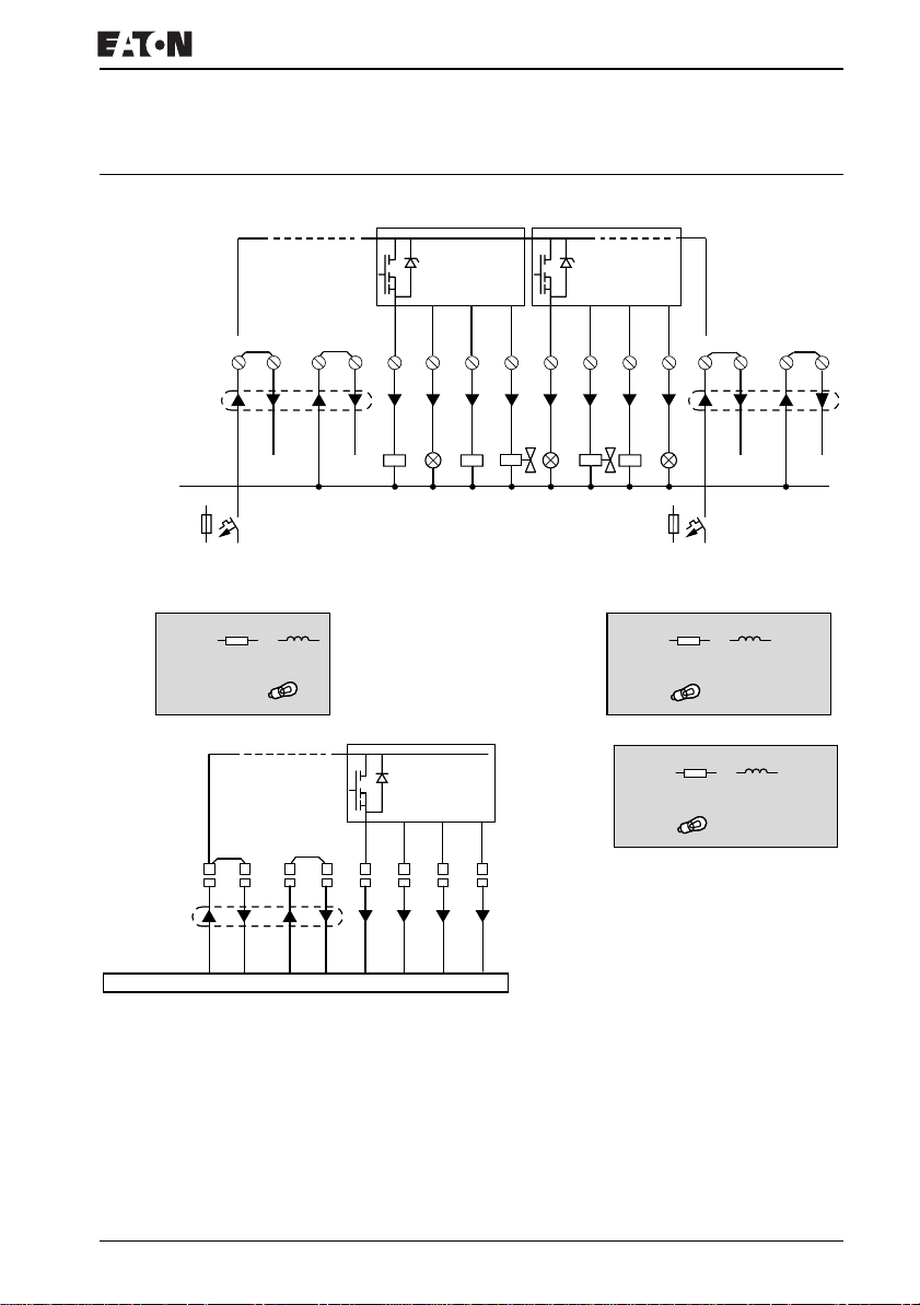
Connecting transistor outputs
Connecting transistor
EZ8..-DC-TC, EZ6..-DC-TE
outputs
24 V
0 V H
f 2.5 A
EZ8..-.DC-… EZ6..-DC-..
R
24 V H
0.5 A
Q1 – Q4
Q5 – Q8
3 W
5 W
Q
F 10 A
0.5 A
24 V
0 V
Q
Q1
Q2 Q3 Q4 Q5 Q6 Q7 Q8
S1 S2 S3 S4 S5 S6 S7 S8
+ 24 V H
(20.4 – 28.8 V H)
+ 24 V H
(20.4 – 28.8 V H)
f 2.5 A
24 V H
24 V H
0.5 A
R
0.5 A
R
24 V
Q
5 W/24 V
5 W/24 V
F
0.5 A
0.5 A
10 A
0 V
Q
24 V
F 10 A
0 V
Q
Q
Q1 Q2 Q3 Q4
Figure 30: Transistor outputs EZ8..-DC-TC, EZ6..-DC-TE
Parallel connection:
Up to four outputs can be connected in parallel in order to
increase the power. The output current will increase in this
case to a maximum of 2 A.
For more information visit: www.EatonElectrical.comMN05013004E 49
Page 54
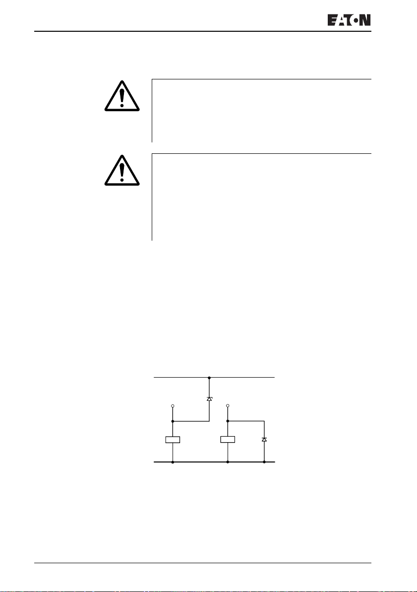
Installation
Caution!
Outputs may only be connected in parallel within a group
(Q1 to Q4 or Q5 to Q8, S1 to S4 or S5 to S8), such as Q1
and Q3 or Q5, Q7 and Q8. Outputs connected in parallel
must be switched at the same time.
Caution!
Please note the following when switching off inductive
loads:
Suppressed inductive loads cause less interference in the
entire electrical system. For optimum suppression the
suppressor circuits are best connected directly in the
proximity of the inductive load.
If inductive loads are not suppressed, the following applies:
Several inductive loads should not be switched off
simultaneously to avoid overheating the driver blocks in the
worst possible case. If in the event of an emergency stop the
+24 V DC power supply is to be switched off by means of a
contact, and if this would mean switching off more than one
controlled output with an inductive load, then you must
provide suppressor circuits for these loads (
J following
diagrams).
+ 24 V H
U
< UZ < 33 V
emax
Q., S.
0 V H
Figure 31: Inductivity with suppressor circuit
Q., S.
Behavior with short-circuit/overload
Should a short circuit or overload occur on a transistor output,
this output will switch off. The output will switch on up to
maximum temperature after the cooling time has elapsed.
This time depends on the ambient temperature and the
For more information visit: www.EatonElectrical.com
MN05013004E50
Page 55
Connecting analog outputs
current involved. If the fault condition persists, the output will
keep switching off and on until the fault is corrected or until the
power supply is switched off (
circuit/overload with EZ..-D.-T..”, Page 293).
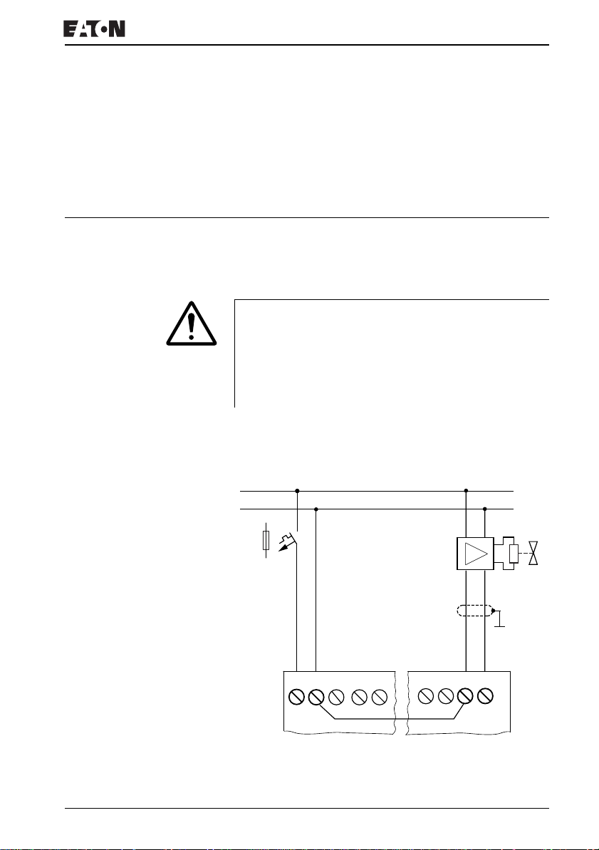
Connecting analog outputs EZ820-DC-RC and EZ822-DC-TC each have an analog
output QA 01, 0 V to 10 V DC, 10 bit resolution (0 to 1023).
The analog output allows you to control servo valves and
other final controlling elements.
Caution!
Analog signals are more sensitive to interference than
digital signals. Consequently, more care must be taken
when laying and connecting the signal lines. Incorrect
switching states may occur if they are not connected
correctly.
J Section “Monitoring of short-
Connecting servo valves
L01 +
L01 –
F1
QA1
0 V
I12
...V
24 V H
0 V
0 V
I1
I2
Figure 32: Connecting servo valves
For more information visit: www.EatonElectrical.comMN05013004E 51
I11
Page 56
Installation
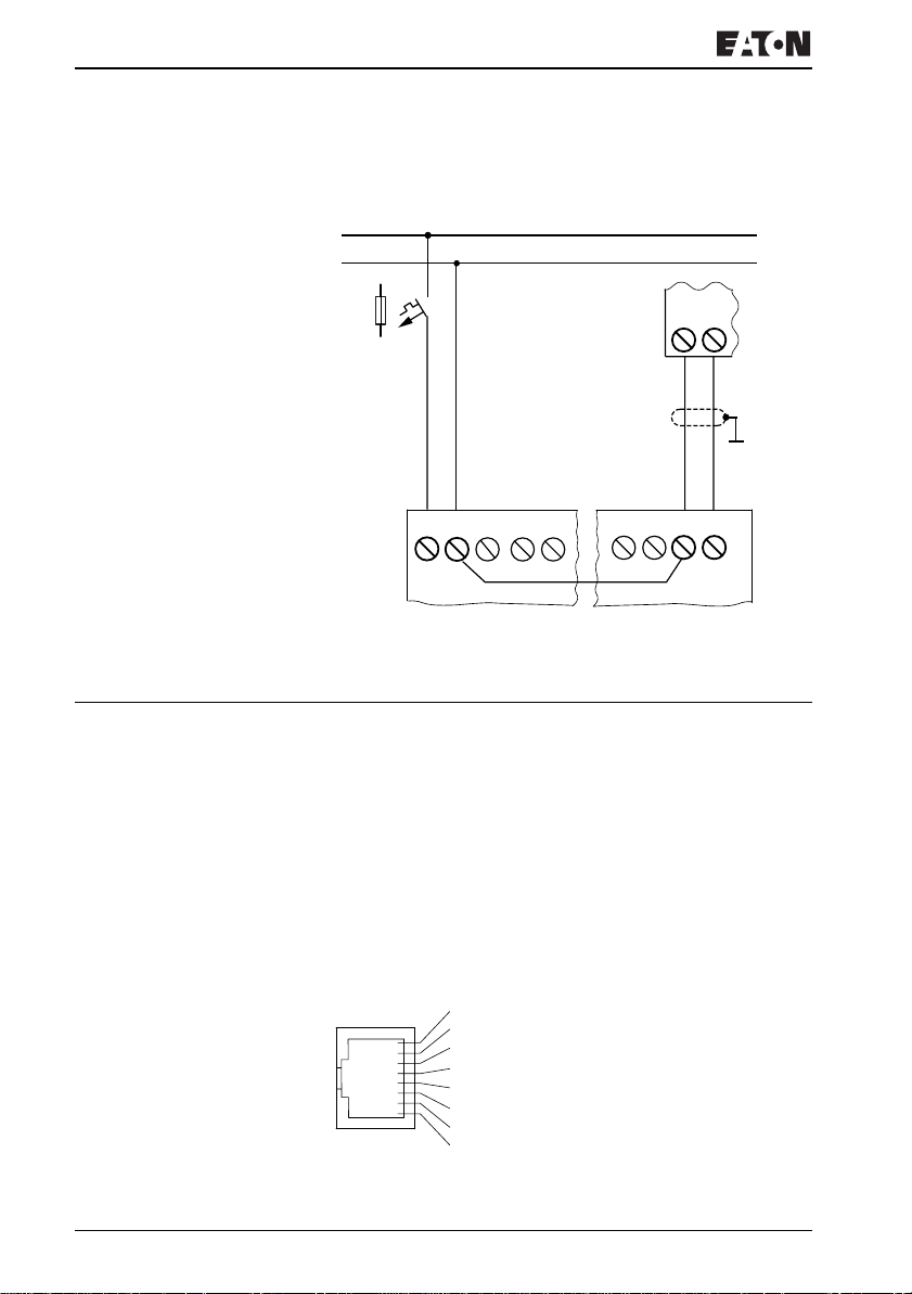
Setpoint entry for a drive
L01 +
L01 –
Connecting the NET network
F1
24 V
24 V H
0 V
0 V
I1
I2
0 V IA
QA1
0 V
I12
I11
Figure 33: Setpoint definition for a drive
EZ800 Control Relay enables the installation and
configuration of the NET network. Up to eight devices can be
connected to this network. Further information can be found in
the Chapter “EZ-NET network”, Page 243.
Accessories
Connection plug:
8-pole RJ45, EZ-NT-RJ45
Connection assignment of the RJ45 socket on the device
1
2
3
4
5
6
7
8
Figure 34: RJ45 socket
For more information visit: www.EatonElectrical.com
MN05013004E52
Page 57
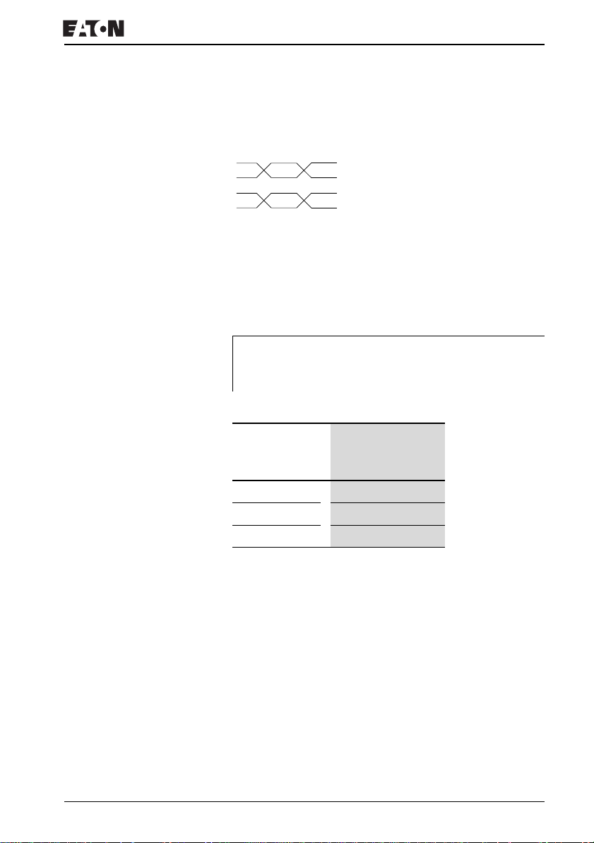
Connecting the NET network
Connection cable:
4-pair twisted cable; a chapter “Technical data”, Page 326
A 1 ECAN_H
A 2 ECAN_L
B 3 GND (Ground)
B 4 SEL_IN
Figure 35: Connection assignment
ECAN_H data cable, pin 1, cable pair A
ECAN_L data cable, pin 2, cable pair A
Ground cable GND, pin 3, cable pair B
Select cable SEL_IN, pin 4, cable pair B
J
ECAN_H, ECAN_L and GND. The SEL_IN cable is only
used for automatic addressing.
Minimum operation with EZ-NET functions with the cables
Table 3: Prefabricated cables, RJ45 plug on both ends
Cable length Type designation
cm
30 EZ-NT-30
80
150
EZ-NT-80
EZ-NT-150
Material for self-manufactured cables
100 m 4 × 0.18 mm
2
: EZ-NT-CAB
Bus termination resistor
The first and last stations in the network must be provided with
a bus termination resistor.
• Value: 124 Ω
• Termination connector: EZ-NT-R
For more information visit: www.EatonElectrical.comMN05013004E 53
Page 58
Installation
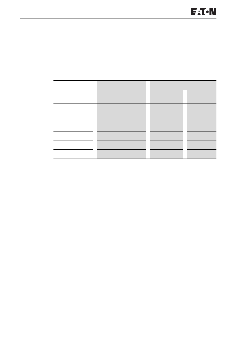
Cable length and cross-sections
For correct operation of the network the cable lengths, crosssections and cable resistances must correspond to the
following table.
Cable length Cable resistance Cross-section
m
up to 40 140 0,13 26
up to 175
up to 250
up to 400
up to 600
up to 1000
mΩ/m mm
70 0.25 to 0.34 23, 22
60 0.34 to 0.5 22, 21, 20
40 0.5 to 0.6 20, 19
26 0.75 to 0.8 18
16 1,5 16
2
AWG
The surge impedance of the cables used must be 120 Ω.
For more information visit: www.EatonElectrical.com
MN05013004E54
Page 59
Connecting the NET network
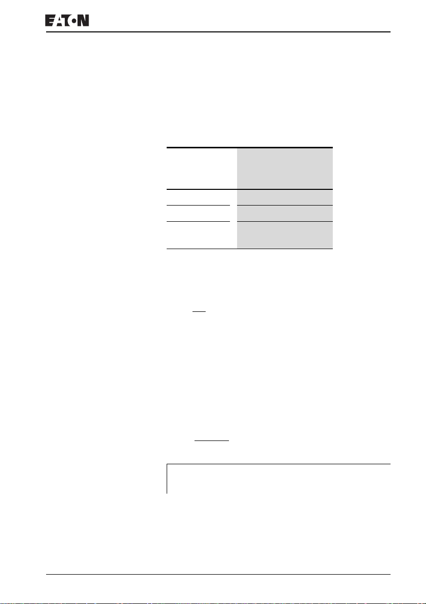
Calculating the cable length with known cable resistance
If the resistance of the cable per unit of length is known
(resistance per unit length R’ in Ω/m), the entire cable
resistance R
depends on the selected baud rates:
must not exceed the following values. RL
L
Baud rate
kBaud
10 to 125 30
250
500
1000
l
= maximum cable length in m
max
= Total cable resistance in Ω
R
L
R’ = Cable resistance per unit length in Ω/m
R
L
=
l
max
R’
Cable resistance R
Ω
25
12
L
Calculating cross-section with known cable lengths
The minimum cross-section is determined for the known
maximum extent of the network.
l = cable length in m
= minimum cable cross-section in mm
S
min
ρ
= resistivity of copper, if not otherwise stated 0.018 Omm2/m
cu
l
× ρ
=
S
min
cu
12,4
2
J
For more information visit: www.EatonElectrical.comMN05013004E 55
cross-section, the next larger cross-section is used.
If the result of the calculation does not yield a standard
Page 60

Installation
Calculating length with known cable cross-section
The maximum cable lengths are calculated for a known
conductor cross-section
l
= cable length in m
max
S = minimum cable cross-section in mm
ρ
= resistivity of copper, if not otherwise stated 0.018 Omm2/m
cu
S × 12.4
l
=
max
ρ
cu
2
Plugging and unplugging network cables
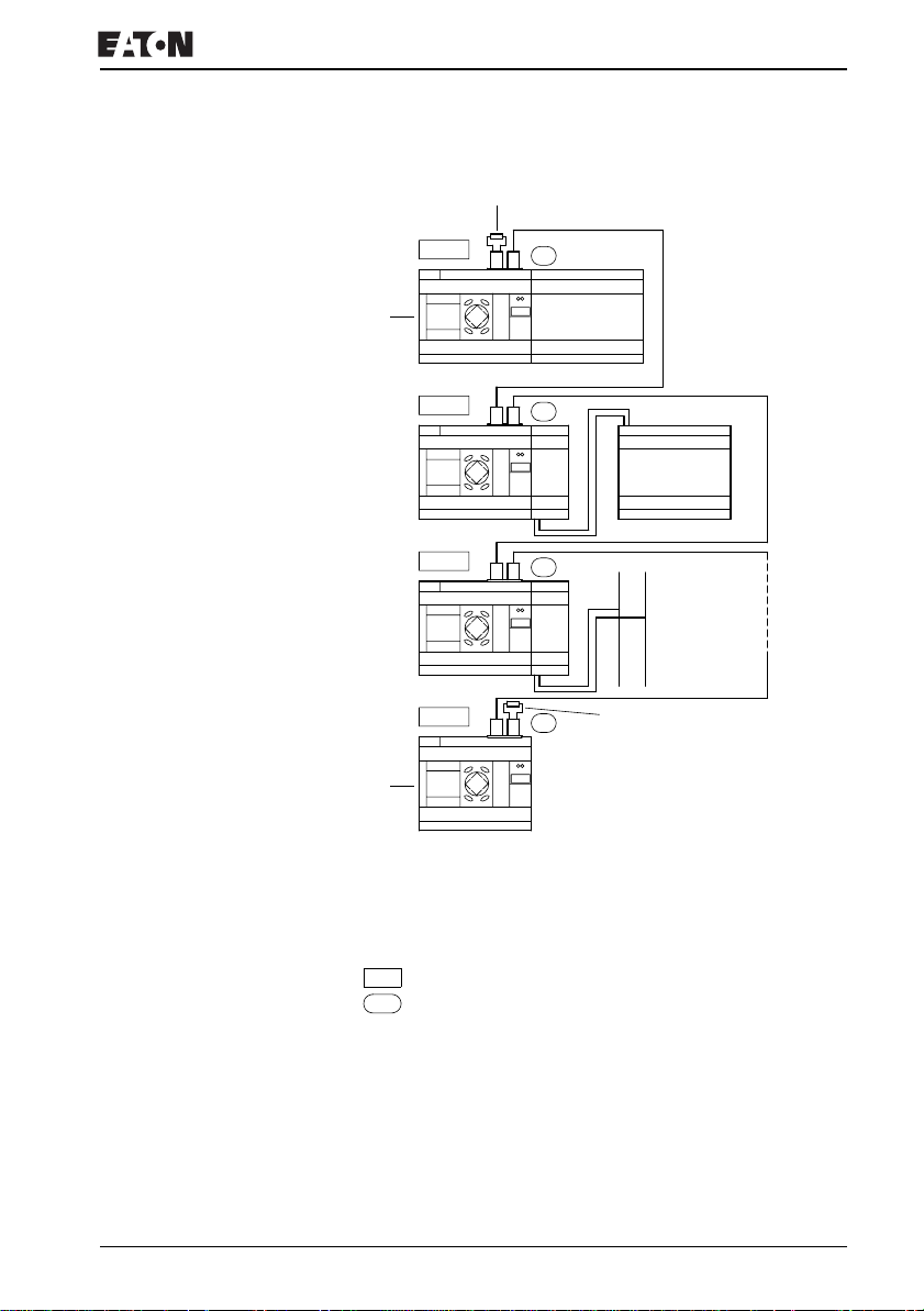
EZ800 Control Relay is provided with two RJ45 network
sockets.
The socket 1 in the first station is for the bus terminating
resistor. For other stations, socket 1 is used for plugging in the
incoming cable. Socket 2 is used for the outgoing cable or for
the bus termination resistor on the last physical station in the
network.
For more information visit: www.EatonElectrical.com
MN05013004E56
Page 61
Connecting the NET network
1
I 1 - 12
12
1
R 1 - 12
Q 1 - 8
2
I 1 - 12
Q 1 - 6
3
I 1 - 12
Q 1 - 6
8
I 1 - 12
12
12
12
S 1 - 8
2
3
8
R 1 - 12
S 1 - 6
AS-Interface
+
Q 1 - 8
Figure 36: Bus termination resistors
First EZ800 Control Relay in the NET
Bus termination resistor
Last EZ800 Control Relay in the NET
Physical location, place
Station number
–
For more information visit: www.EatonElectrical.comMN05013004E 57
Page 62
Installation
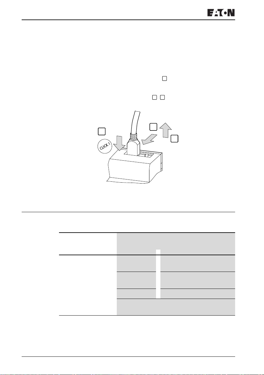
Both RJ45 interfaces are visible after the cover plate has been
removed.
When a cable is plugged in, the mechanical connection must
be audible (click) and visible .
1
Before a plug or cable is removed, the mechanical locking
feature must be undone , .
2 3
1
2
3
Figure 37: Plugging and unplugging cables
Expanding inputs/outputs You can add expansion units to all EZ800 Control Relay in
order to increase the number of inputs and outputs:
Expandable EZ basic
units
EZ8..-..-R..
EZ8..-..-T..
Expansion units
EZ618-..-RE • 12 AC inputs,
• 6 relay outputs
EZ620-..-TE • 12 DC inputs,
• 8 transistor outputs
EZ202-RE 2 relay outputs, common
Special expansion units for connecting to other bus
systems are shown in the latest product catalog.
1)
1) Common supply for multiple outputs
For more information visit: www.EatonElectrical.com
MN05013004E58
Page 63
Expanding inputs/outputs
Local expansion
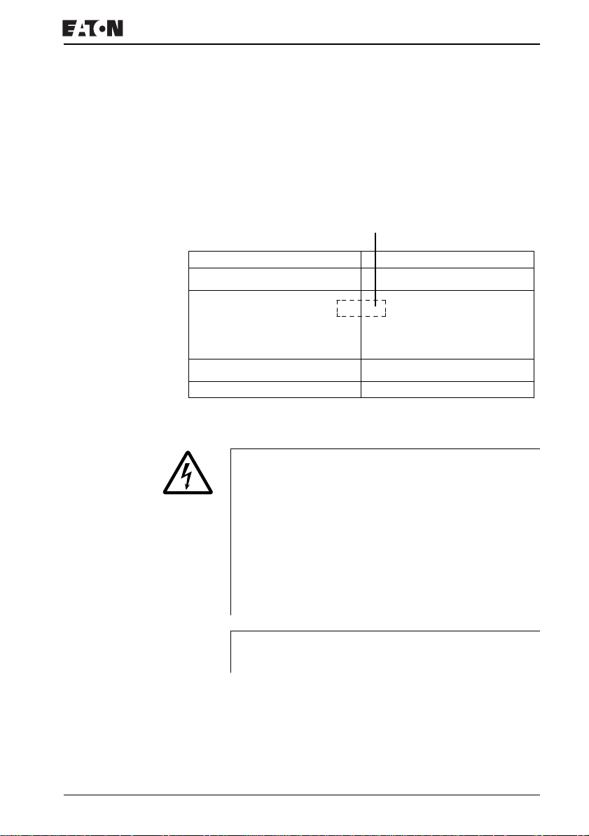
Local expansion units are connected directly next to the basic
unit.
XConnect the EZ expansion unit via the EZ-LINK-DS plug
connector.
EZ-LINK-DS
EZ8..-..-R..
EZ82.-DC-T..
Figure 38: Connecting local expansions with EZ800 Control Relay
The following electrical separation is implemented between
the EZ8..-..-.C. basic unit and the expansion device
(separation always in local connection of expansion unit)
• Simple isolation 400 V AC (+10 %)
• Safe isolation 240 V AC (+10 %)
Units may be destroyed if the value 400 V AC +10 % is
exceeded, and may cause the malfunction of the entire
system or machine!
J
Basic unit and expansion unit can be provided with different
DC power supplies.
EZ6..-..-RE
EZ6..-..-TE
EZ2…
For more information visit: www.EatonElectrical.comMN05013004E 59
Page 64
Installation
Remote expansion
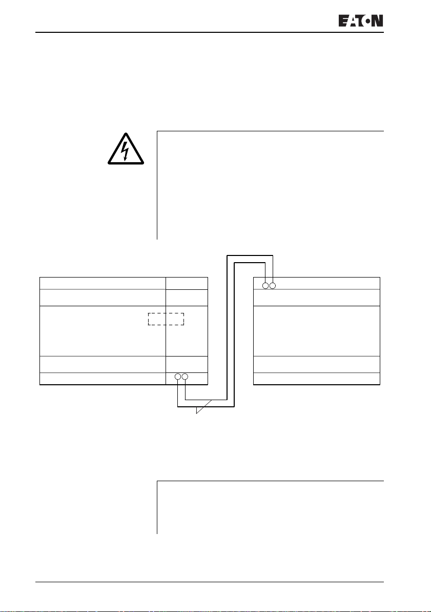
Remote expansion units can be installed and run up to 30 m
away from the basic unit.
Warning!
The two-wire or multiple-wire cable between the devices
must adhere to the insulation voltage requirement which is
stipulated for the installation environment. Otherwise, a
fault (ground fault, short-circuit) may lead to the destruction
of the units or injury to persons.
A cable such as NYM-0 with a rated operational voltage of
U
= 300/500 V AC is normally sufficient.
e
E+ E–
EZ8…
EZ200-EZ
E+ E–
U
= 300/500 V
e
EZ…-AC-…E
Figure 39: Connecting remote expansions to the EZ800 Control
Relay
EZ6..RE/TE
Terminals E+ and E– of the EZ200-EZ are protected
J
against short-circuits and polarity reversal.
Functionality is only ensured if E+ is connected with E+ and
E- with E-.
For more information visit: www.EatonElectrical.com
MN05013004E60
Page 65

3 Commissioning
Switching on Before startup check whether the power supply, inputs,
outputs and the EZ-NET connection are properly connected:
• 24 V DC version:
– Terminal +24 V: +24 V voltage:
– Terminal 0 V: 0 V voltage:
– Terminals I1 to I12, R1 to R12:
Actuation via +24 V
• 230 V AC version:
– Terminal L: Phase conductor
– Terminal N: Neutral conductor N
– Terminals I1 to I12, R1 to R12: Actuation via phase
conductor L
If you have already integrated devices into a system, secure
any parts of the system connected to the working area to
prevent access and ensure that no-one can be injured if, for
example, motors start up unexpectedly.
Setting the menu language When you switch on EZ for the first time, you will be asked to
select the menu language.
ENGLISH å
DEUTSCH
FRANCAIS
ESPANOL
XUse the cursor buttons
required.
– English
– German
– French
Í or Ú to select the language
– Spanish
– Italian
– Portuguese
–Dutch
– Swedish
– Polish
–Turkish
For more information visit: www.EatonElectrical.com 61MN05013004E
Page 66
Commissioning
XPress OK to confirm your choice and press ESC to exit the
menu.
EZ will then switch to the Status display.
J
EZ operating modes EZ has one operating mode - RUN and STOP.
You can change the language setting at a later date, if you
wish, see
Page 266.
If you do not set the language, EZ will display this menu
every time you switch on and wait for you to select a
language.
In RUN mode EZ continuously processes a stored circuit
diagram until you select STOP or disconnect the power. The
circuit diagram, parameters and the EZ settings are retained
in the event of a power failure. All you will have to do is reset
the real-time clock after the back-up time has elapsed.Circuit
diagram entry is only possible in STOP mode.
Caution!
In RUN mode, EZ will immediately run the program saved
in the unit when the power supply is switched on. This will
not happen if STOP mode was set as startup mode. In RUN
mode outputs are activated according to the switch logic
involved.
The following applies to devices without display/operating
unit:
J Section “Changing the menu language”,
• Memory card containing a valid circuit diagram is fitted.
• Device is switched on.
If the device does not contain a circuit diagram, the circuit
diagram on the memory card is loaded automatically and the
device processes the circuit diagram immediately in RUN
mode.
For more information visit: www.EatonElectrical.com
MN05013004E62
Page 67
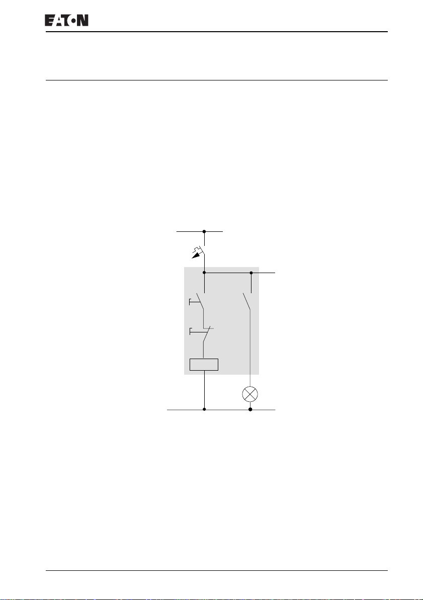
Creating your first circuit diagram
Creating your first circuit
diagram
The following single line diagram takes you step by step
through wiring up your first circuit diagram. In this way you will
learn all the rules, quickly enabling you to use EZ for your own
projects.
As with conventional wiring, you use contacts and relays in
the EZ diagram. With EZ, however, you no longer have to
connect up components individually. At the push of a few
buttons, the EZ circuit diagram produces all the wiring
required. All you have to do is then connect any switches,
sensors, lamps or contactors you wish to use.
L01+
F1
S1
S2
K1
K1
L01-
Figure 40: Lamp controller with relays
For more information visit: www.EatonElectrical.comMN05013004E 63
H1
Page 68
Commissioning
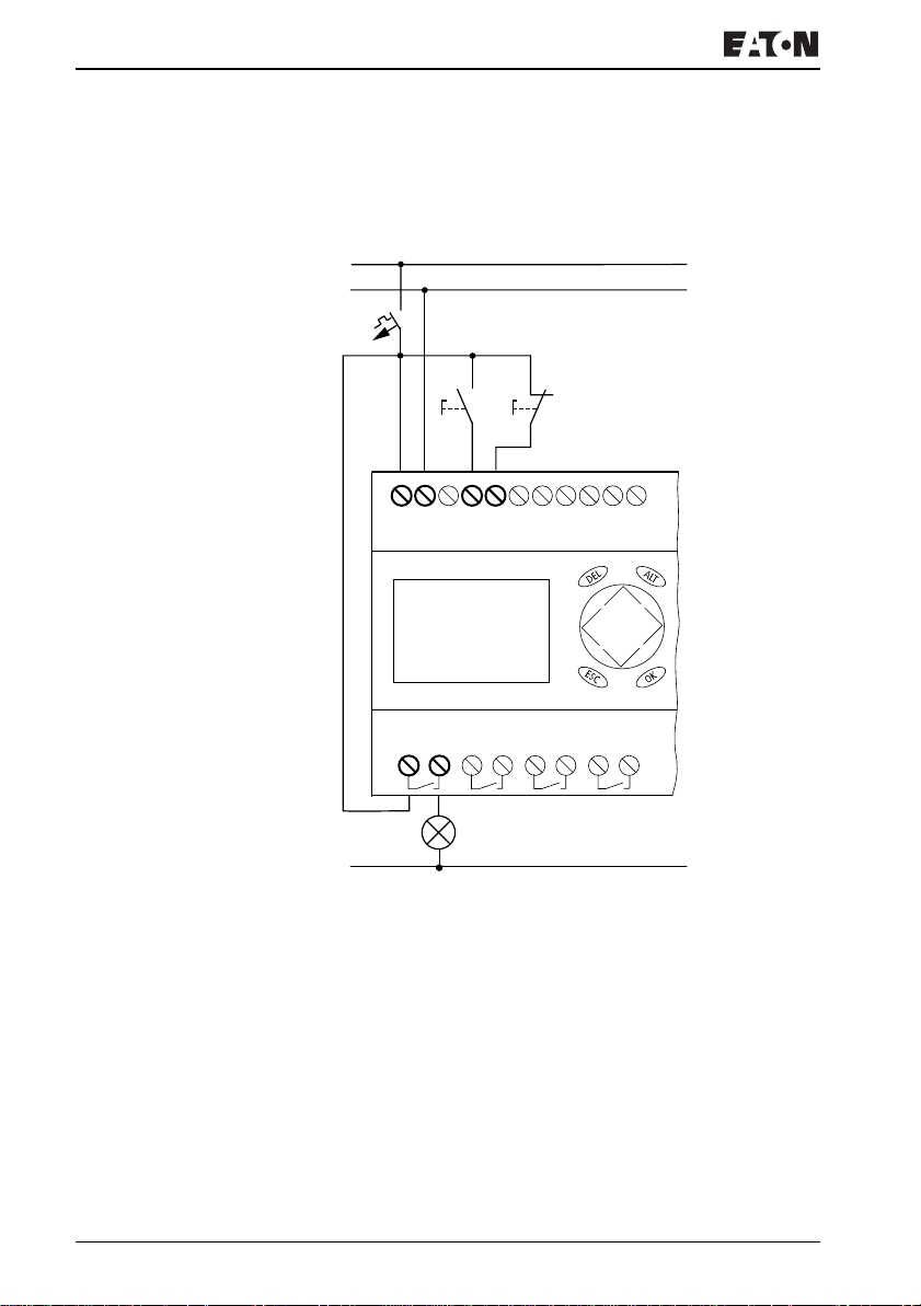
In the following example, EZ carries out all the wiring and
performs the tasks of the circuit diagram shown below.
L01 +
L01 –
F1
S1 S2
+24V 0V I1 I2
I 01----I 02- --Ä Q 01
Q1
2
1
H1
L01 –
Figure 41: Lamp controller with EZ
For more information visit: www.EatonElectrical.com
MN05013004E64
Page 69
Creating your first circuit diagram
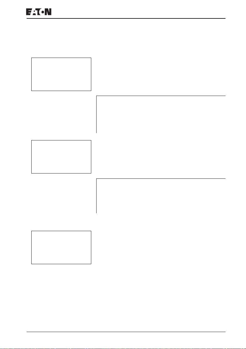
Starting point Status display
I ............
IPMO 02:00
Q........ STOP
J
PROGRAM...
STOP å RUN
PARAMETERS
SET CLOCK
J
When you switch on EZ, it opens the Status display
immediately to show the switching state of the inputs and
outputs. It also indicates whether EZ is already running a
circuit diagram.
The examples were written without the use of expansion
units. If an expansion unit is connected, the Status display
will first show the status of the basic unit and then the status
of the expansion unit before showing the first selection
menu.
XPress OK to switch to the main menu.
Press OK to switch to the next menu level, and press ESC to
move one level back.
OK has two other functions:
•Press OK to save modified settings.
• In the circuit diagram, you can also press OK to insert
and modify contacts and relay coils.
In this case EZ must be in STOP mode.
CIRCUIT DIAGRAM
FUNCTION RELAYS
XPress OK 2 × to enter the circuit diagram display via menu
items PROGRAM…
create the circuit diagram.
For more information visit: www.EatonElectrical.comMN05013004E 65
J PROGRAM. This is where you will
Page 70
Commissioning
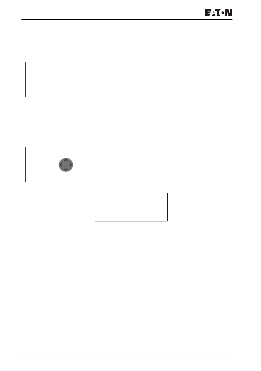
Ê
Circuit diagram display
The circuit diagram display is currently empty. The cursor
flashes at the top left, which is where you will start to create
your diagram.
L: 1 C:1 B:7944
M
ККККККК-ККККККК-
m
ККККККК-КККККККККККККК-ККÊÊÊÊÊ-
L: 1 C:1 B:7944
l
L
The location of the cursor is indicated in the status line. L: =
Circuit connection (line), C: = Contact or coil (contact), B: =
Free memory available in bytes. Start value 7944, with the first
three circuit connections already generated.
The EZ800 Control Relay circuit diagram supports 4 contacts
and one coil in series. The EZ800 Control Relay display can
display 6 circuit diagram contact fields.
Use the
Í Ú ú í cursor buttons to move the cursor over the
invisible circuit diagram grid.
The first four columns are contact fields, the fifth column is a
coil field. Each line is a rung. EZ automatically connects the
contact to the power supply.
I 01----I 02--...-Ä Q 01
L: 1 C:1 B:7944
Figure 42: Circuit diagram with inputs I1, I2 and output Q1
XNow try to wire up the following EZ diagram.
Switches S1 and S2 are at the input.
I01 and I02 are the
contacts for the input terminals. Relay K1 is represented by
the relay coil
function, in this case a relay coil acting as a contactor.
ÄQ01. The symbol -Ä identifies the coil's
Q01
is one of the EZ output relays.
For more information visit: www.EatonElectrical.com
MN05013004E66
Page 71
Creating your first circuit diagram
From the first contact to the output coil
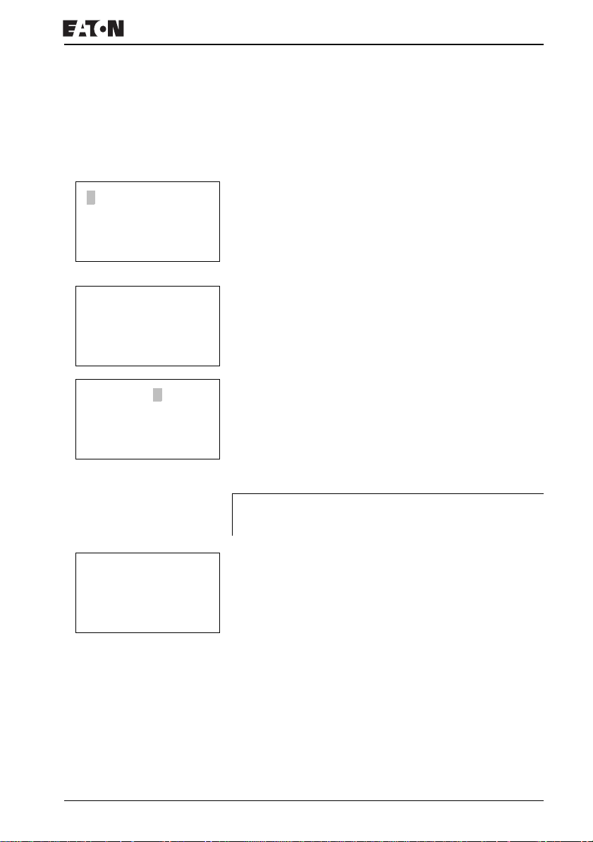
With EZ, you work from the input to the output. The first input
contact is
I01.
I 01
L: 1 C:1 B:7944
I 01 Ê
L: 1 C:1 B:7944
I 01 I 02
L: 1 C:2 B:7944
J
-I 02 Ê
XPress OK.
EZ proposes the first contact
I flashes and can be changed, for example, to a P for a
pushbutton input using the cursor buttons
I01 at the cursor position.
Í or Ú. However,
nothing needs to be changed at this point.
XPress OK 2 ×, to move the cursor across the
01 to the
second contact field.
You could also move the cursor to the next contact field using
the
> cursor button.
XPress OK.
Again, EZ inserts a contact
Change the contact number to
I01 at the cursor position.
I02, so that break contact S2
can be connected to input terminal I2.
XPress OK so that the cursor jumps to the next position and
press cursor button
Í or Ú to change the number to 02.
You can press DEL to delete a contact at the cursor
position.
XPress OK to move the cursor to the third contact field.
You do not need a third relay contact, so you can now wire the
contacts directly to the coil field.
L: 1 C:3 B:7944
For more information visit: www.EatonElectrical.comMN05013004E 67
Page 72
Commissioning
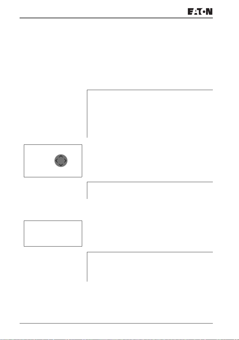
Wiring
J
ККККККК-ККККККК-
M
l
m
ККККlКК-ККККККК-
L
ККККККК-ККККККК-
L: 1 C:1 B:7944
J
-I 02 l
EZ displays a small arrow
creating the wiring.
Press ALT to activate the wiring arrow cursor and use the
cursor buttons
ALT also has two other functions depending on the cursor
position:
• In the left contact field, you can press ALT to insert a new
empty rung.
• The contact under the cursor can be changed between a
make and break contact by pressing the ALT button.
The wiring arrow works between contacts and relays. When
you move the arrow onto a contact or relay coil, it changes
back to the cursor and can be reactivated with ALT if required.
EZ automatically wires adjacent contacts in a rung up to the
coil.
XPress ALT to wire the cursor from
field.
The cursor changes into a flashing wiring arrow and
automatically jumps to the next possible wiring position.
Í Ú ú í to move it.
l in the circuit diagram when
I02 through to the coil
XPress the cursor button
up to the coil field.
J
For more information visit: www.EatonElectrical.com
You can use DEL to erase a connection at the cursor or
arrow position. Where connections intersect, the vertical
connections are deleted first, then, if you press DEL again,
the horizontal connections are deleted.
í. Contact I02 will be connected
MN05013004E68
Page 73
Creating your first circuit diagram
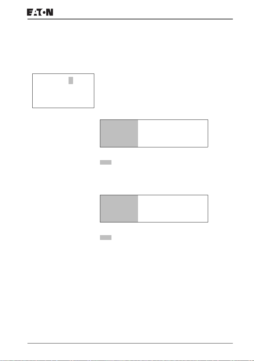
XPress the cursor button í again.
The cursor will move to the coil field.
--------Ä Q 01
L: 1 C:1 B:7944
XPress OK.
EZ inserts the relay coil
and the output relay
Q 01. The specified coil function Ä
Q01 are correct and do not have to be
changed.
Your first working EZ circuit diagram now looks like this:
I 01----I 02-------------------Ä Q 01
L: 1 C:1 B:7944
Figure 43: Your first circuit diagram
= visible area
XPress ESC to leave the circuit diagram display.
The SAVE menu appears.
I 01----I 02-------------------Ä Q 01
SAVE
Figure 44: SAVE menu
= visible area
XPress the OK button.
The circuit diagram is stored.
Once you have connected pushbutton actuators S1 and S2,
you can test your circuit diagram straight away.
For more information visit: www.EatonElectrical.comMN05013004E 69
Page 74
Commissioning
Testing the circuit diagram
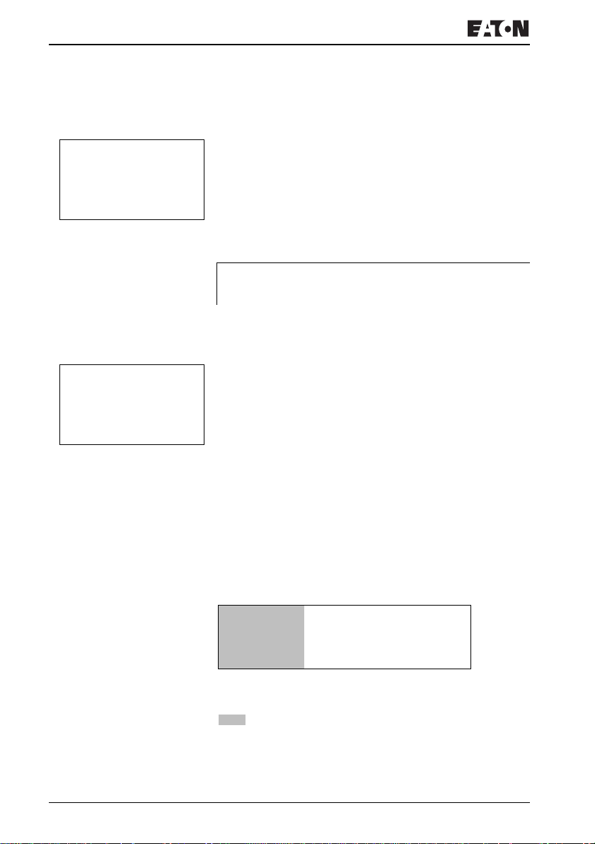
PROGRAM...
STOP å RUN
PARAMETERS
SET CLOCK
J
I 12..........
IPMO 14:42
Q 1....... RUN
XSwitch to the main menu and select the STOP RUN menu
option.
With a tick at RUN or STOP you switch to the RUN or STOP
operating modes.
EZ runs in the mode indicated by the tick.
XPress the OK button. EZ will change to RUN mode.
The mode assigned with the tick is always active.
The Status display shows the current mode and the switching
states of the inputs and outputs.
XChange to the Status display and press pushbutton
actuator S1.
The contacts (boxes) for inputs I1 and I2 are activated and
relay Q1 picks up. This is indicated on the numbers which are
displayed.
Power flow display
EZ allows you to check rungs in RUN mode. This means that
you can check your circuit diagram via the built-in power flow
display while it is being processed by the EZ.
XChange to the Circuit diagram display and press
pushbutton actuator S1.
The relay picks up. EZ shows the power flow.
I 01====I 02===================Ä Q 01
L: 1 C:1 RUN
Figure 45: Power flow display: Inputs I1 and I2 are closed, relay
Q1 has picked up
= visible area
For more information visit: www.EatonElectrical.com
MN05013004E70
Page 75
Creating your first circuit diagram
XPress pushbutton actuator S2, that has been connected as
a break contact.
The circuit connection is interrupted and relay Q1 drops out.
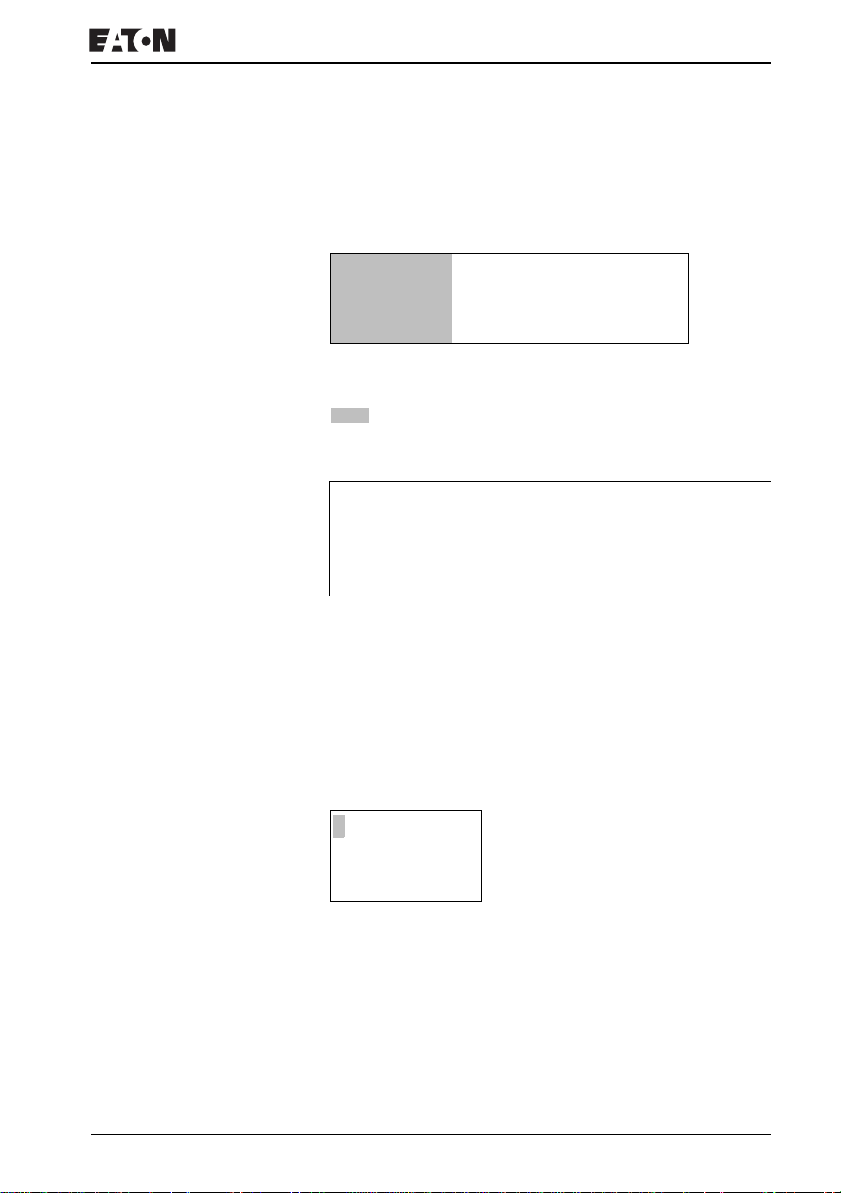
I 01====I 02-------------------Ä Q 01
L: 1 C:1 RUN
Figure 46: Power flow display: Input I1 is closed, input I2 is open,
relay Q1 has picked up
= visible area
XPress ESC to return to the Status display.
J
entirely completed.
EZ simply ignores any incomplete wiring that is not yet
working and only runs the finished wiring.
Power flow display with Zoom function
EZ enables you to check the following at a glance:
• all four contacts plus one coil in series
• and 3 circuit connections
XChange to the Circuit diagram display and press the ALT
button. Press pushbutton actuator S1.
With EZ you can test parts of a circuit diagram before it is
â==â========Äâ
L: 001 I 01
Figure 47: Power flow display in Zoom function: Input I1 and I2 are
closed, relay Q1 picked up
â Contact closed, coil is triggered:
# Contact opened, coil dropped out
For more information visit: www.EatonElectrical.comMN05013004E 71
Page 76
Commissioning
XPress pushbutton actuator S2, that has been connected as
a break contact.
The rung is interrupted and relay Q1 drops out.
â==#-------- #
L: 001 I 01
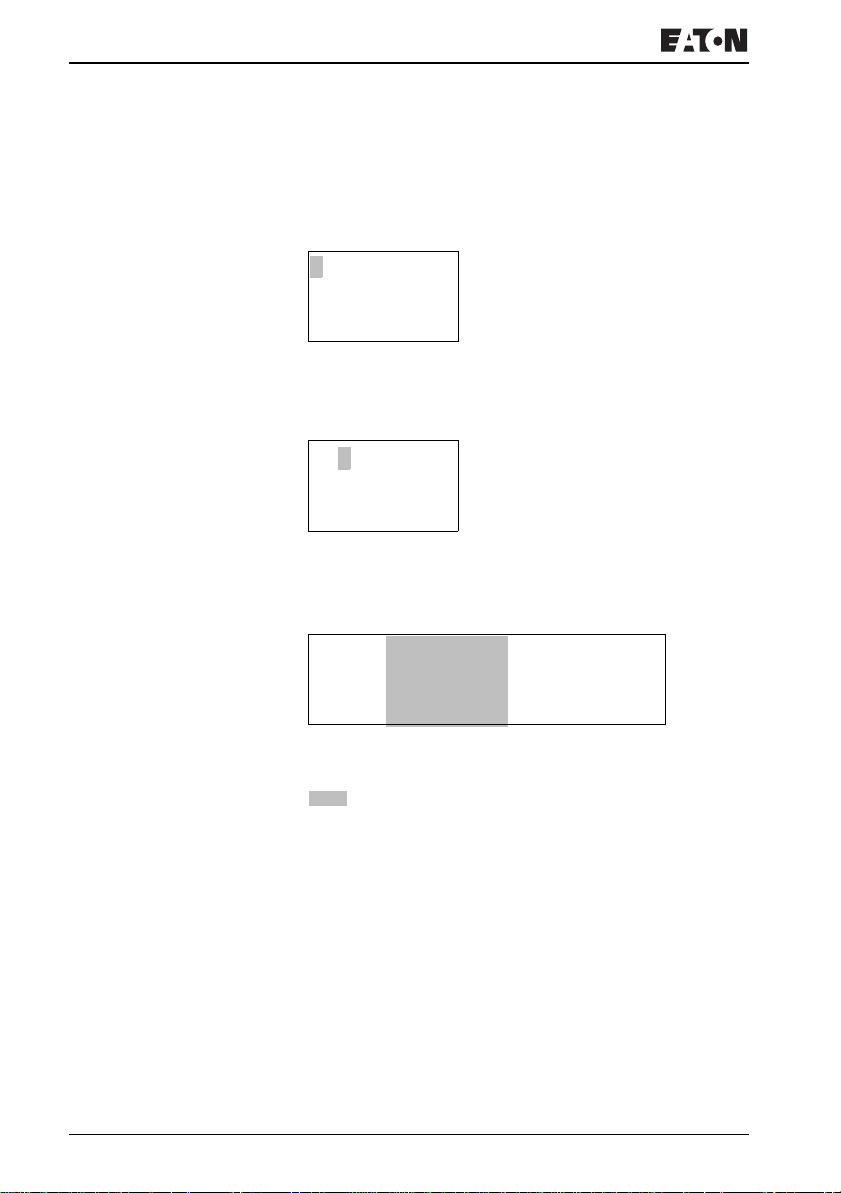
Use the cursor buttons
Í Ú ú í to move between the
contacts or coil.
XPress the cursor button
‚==#-------- #
L: 002 I 02
í.
The cursor moves to the second contact.
XPress the ALT button. The display changes to display
status with contact and/or coil designation.
I 01====I 02-------------------Ä Q 01
L: 1 C:2 RUN
Figure 48: Power flow display: Input I1 is closed, input I2 is open,
relay Q1 has picked up
= visible area
For more information visit: www.EatonElectrical.com
MN05013004E72
Page 77

Creating your first circuit diagram
Deleting the circuit diagram
XSwitch the EZ to STOP mode.
PROGRAM...
DELETE PROGRAM
J
EZ must be in STOP mode in order to extend, delete or
modify the circuit diagram.
XUse PROGRAM… to switch from the main menu to the next
menu level.
XSelect DELETE PROGRAM
The EZ will display the prompt DELETE?
XPress OK to delete the program or ESC to cancel.
XPress ESC to return to the Status display.
Fast circuit diagram entry
You can create a circuit-diagram in several ways: The first
option is to enter the elements in the circuit and then to wire
all the elements together. The other option is to use the
enhanced operator guidance of the EZ and create the circuit
diagram in one go, from the first contact through to the last
coil.
If you use the first option, you will have to select some of the
elements in order to create and connect up your circuit
diagram.
The second, faster option is what you learned in the example.
In this case you create the entire circuit connection from left to
right.
For more information visit: www.EatonElectrical.comMN05013004E 73
Page 78
Commissioning
Configuring an EZ-NET network
If you want to work with the EZ-NET network and
communicate with several stations, the network must be
configured first.
Proceed as follows:
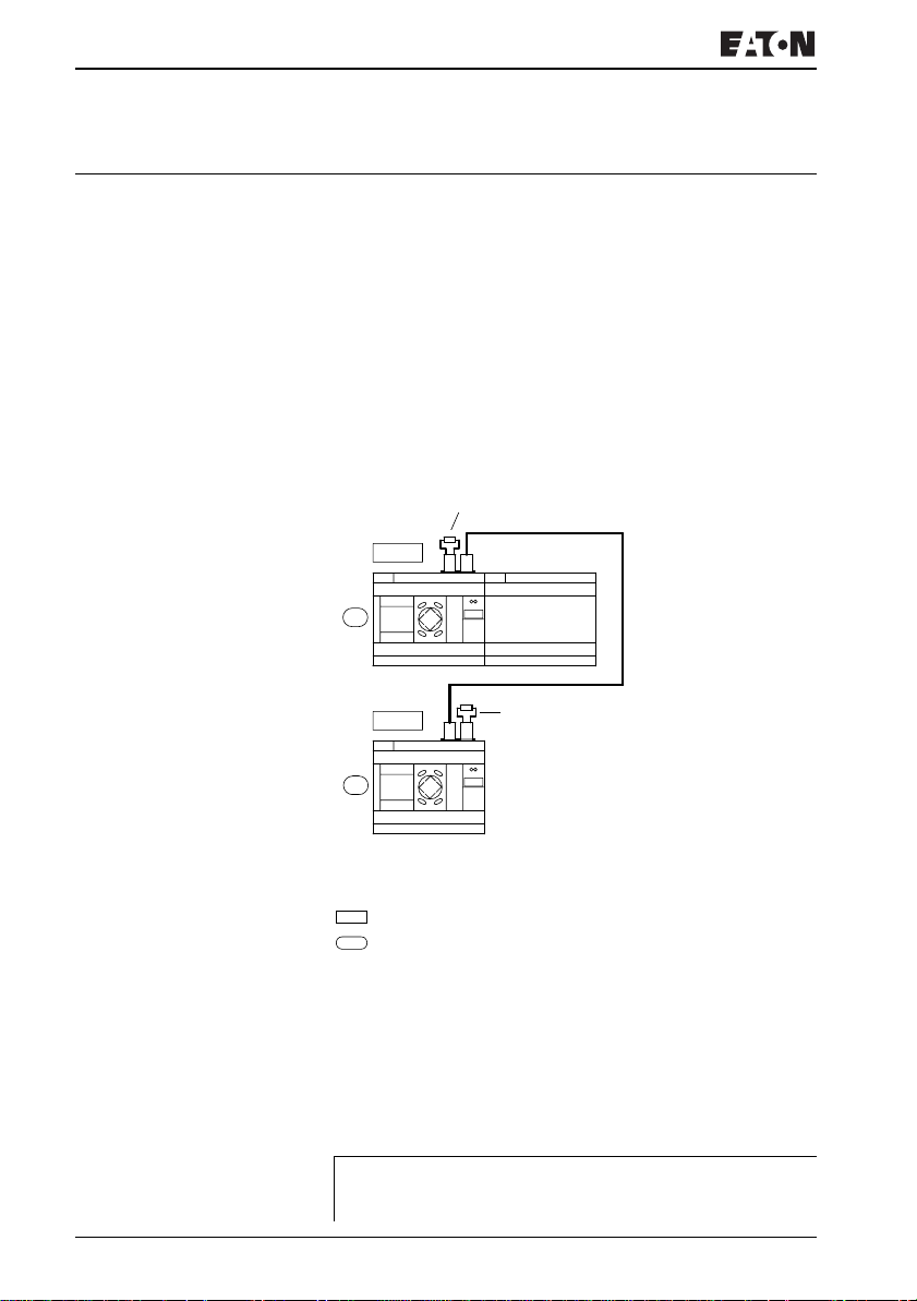
XConnect all network stations. EZ-NET socket 2 to EZ-NET
socket 1.
XThe first station 1 (socket 1) and the last station
(socket 2) must be provided with a network termination
resistor .
XConnect all stations to the power supply.
1
I1 – I12
1
Q1 – Q8
2
I1 – I12
2
Q1 – Q6
R1 – R12
S1 – S8
Figure 49: Example topology with two EZ-NET stations
Network termination resistor
Physical location
Station number
XSwitch on the power supply on all stations.
XEnsure that all stations have a voltage supply. The POW
LED must light up or flash. It is only possible to configure
the stations which are supplied with voltage.
XProceed to the first physical station (Location 1). This
station has the termination resistor inserted in socket 1.
The following tasks are only possible in STOP mode.
J
For more information visit: www.EatonElectrical.com
MN05013004E74
Page 79
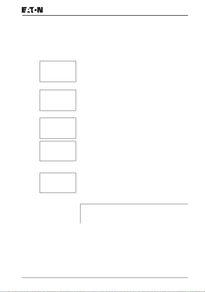
SECURITY...
SYSTEM...
MENU LANGUAGE
CONFIGURATOR...
Configuring an EZ-NET network
Entering the network station number
XSimultaneously press the DEL and ALT buttons while EZ
displays the Status display.
The System menu appears
Select the CONFIGURATOR menu option.
XPress the OK button.
NET..
.
NET PARAMETERS..
STATIONS...
CONFIGURE
NET-ID : 00 Æ
BAUDRATE: 125KB
BUSDELAY: 00
SEND IO å æ
REMOTE RUN
REMOTE IO
NET-ID : 01 Æ
BAUDRATE: 125KB
BUSDELAY: 00
SEND IO å æ
REMOTE RUN
REMOTE IO
J
The NET menu appears.
XPress the OK button.
The NET PARAMETERS… menu appears.
XPress the OK button.
XPress the OK button and select the station number with
and
Ú. In this case the station number (NET-ID) is “01”.
XPress the OK button.
XExit the NET PARAMETERS menu with ESC.
The station designated station number 1 is the active
station. For this reason the REMOTE RUN and
REMOTE IO functions are not available.
Í
For more information visit: www.EatonElectrical.comMN05013004E 75
Page 80
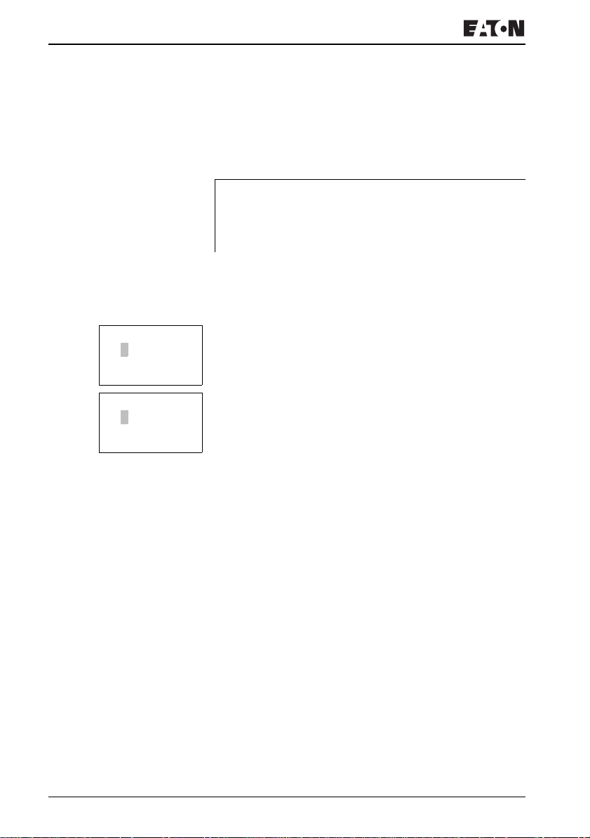
Commissioning
Entering network stations
Only the network station at physical location 1 with station
number 1 has a station list.
J
1 1 Æ
2 0
3 0
40 æ
1 1 Æ
2 2
3 0
40 æ
The left-hand column is the physical location. You can only
assign a physical location to unused station numbers.
Physical location 1 is permanently assigned to station
number 1.
XUse the
Í and Ú cursor buttons to select the STATION
menu and press the OK button.
XProceed to the station with physical address 2.
XSelect the required physical location with the
Í and Ú
cursor buttons. Press the OK button.
XUse cursor buttons
Í and Ú to select station number 2.
XPress the OK button.
At physical location 2, the station has been assigned station
address 2.
XPress ESC to return to the STATION menu item.
For more information visit: www.EatonElectrical.com
MN05013004E76
Page 81
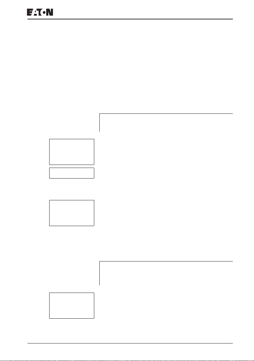
Configuring an EZ-NET network
Configuring an EZ-NET network
The EZ-NET network can only be configured by station 1.
Requirement:
All stations are correctly connected to the network and the
termination resistors have been connected.
All stations have a power supply and are in STOP mode. The
POW LED is permanently lit. The NET LED is permanently lit.
J
NET PARAMETERS..
STATIONS...
CONFIGURE
CONFIGURE ?
CONFIGURATION
IN
PROGRESS.
J
ERR:ID-KONFLIKT
CONFIGURATION
OVERWRITE?
If the connected stations are being configured, all stations
automatically switch to the STOP mode.
XProceed to the CONFIGURE menu item and press the OK
button.
You will be asked to acknowledge whether you want to
configure the system.
XPress the OK button.
The message on the left appears:
All NET LEDs on the stations which are assigned station
numbers higher than 1 (2 to 8) switch to the OFF state of EZNET.
As soon as the configuration has been successfully
completed, the NET LEDs on all stations flash. The EZ-NET
network is ready for operation.
An error message will appear if a station is assigned with a
station address which does not correspond to the physical
location in the station list.
If you want to overwrite the station address press the OK
button. The configuration can be aborted by pressing the ESC
button.
For more information visit: www.EatonElectrical.comMN05013004E 77
Page 82

Commissioning
Changing the EZ-NET network configuration
The configuration of the EZ-NET network can be modified at
any time at station 1, physical location 1.
XThe NET parameters are modified as described for
inputting parameters for the first time.
Station addresses in the STATIONS menu are changed as
follows:
XGo to the physical location which is to be modified.
XPress the OK button.
J
J
Existing station numbers can only be modified to free, nonassigned station numbers. If all eight numbers are
assigned, all station numbers which are to be modified must
be set to zero. Thereafter, all station numbers can be
reassigned. (EZ800 Control Relay sets all station numbers
to zero which are assigned with a physical location behind
the leading zero.)
XSelect the required station number with the
buttons and confirm your input with the OK button.
XConfigure all EZ-NET stations again using the
CONFIGURATION menu.
Further information concerning the EZ-NET network topic
can be found in Chapter “EZ-NET network”, Page 243.
Í and Ú cursor
For more information visit: www.EatonElectrical.com
MN05013004E78
Page 83
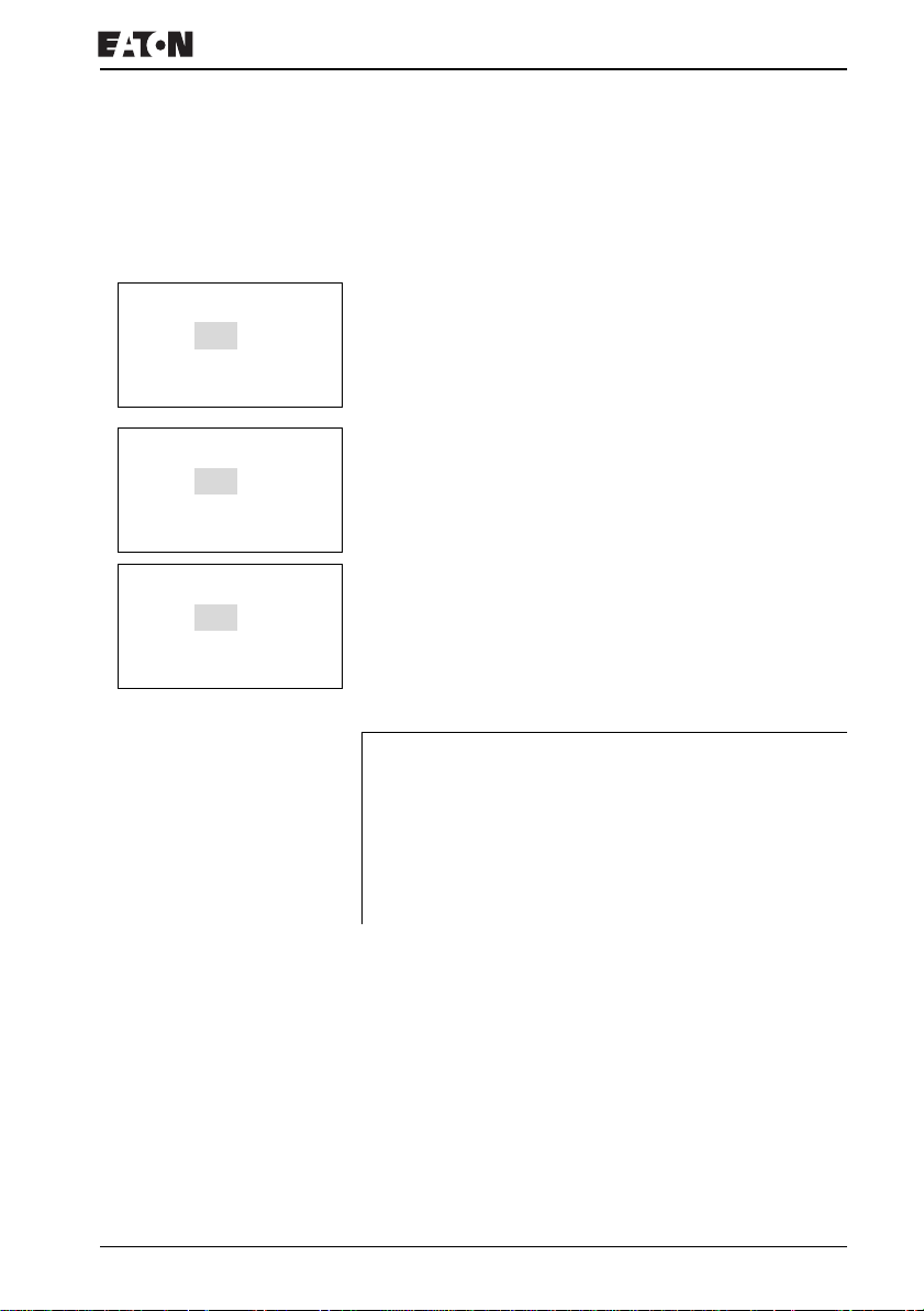
Configuring an EZ-NET network
Displaying the Status display of other stations
On every device with a display, you can display the states of
the inputs and outputs of each network station.
1I12..........
I NT1 PMO 06:42
1Q1....... RUN
3I12.....7....
I NT3 PMO 06:42
3Q1.3..6.. RUN
3R12.....7....
I NT3 DC PMO 06:45
3S1.3..6.. RUN
J
XChange to the Status display and press the ESC button.
The cursor changes to the display of the network station NT..
and flashes. The station number is displayed in front of the
inputs and outputs.
XChange to the number of the required station with the
and
Ú cursor buttons.
Í
XPress the OK button.
XIf you want to view the state of the inputs and outputs of a
local expansion, press the OK button.
If you press the ESC button again or the OK button, the
display of the input and output states of the station is
terminated.
The station showing the status on its display cannot read its
own data from the network.
Example: NT3 flashes on station 3. The inputs and outputs
3I.., 3R.., 3Q.. and 3S.. cannot be displayed.
If the NT3 display is not flashing, the inputs and outputs are
shown.
For more information visit: www.EatonElectrical.comMN05013004E 79
Page 84

Page 85
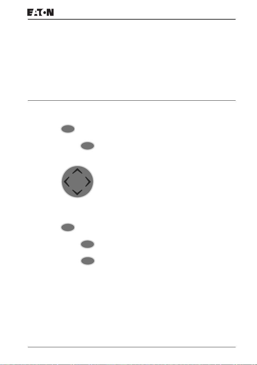
4 Wiring with EZ800 Control Relay
This chapter describes all the functions available with EZ800
Control Relay.
EZ800 Control Relay operation
DEL
ESC
Buttons for drawing circuit diagrams and function block usage
Delete circuit connection, contact, relay or empty line in the
circuit diagram
Toggle between break and make contact
ALT
Connect contacts and relays
Add rungs
ÍÚ
Change values
Cursor up, down
Change position
úí
Cursor left, right
Cursor buttons set as P buttons:
ú
í
Input P1,
Input P3,
Í
Ú
Input P2
Input P4
Undo setting from previous OK
Exit current display or menu
Change, add contact/relay
OK
Save setting
Terminal mode on/off
*
For more information visit: www.EatonElectrical.com 81MN05013004E
Page 86

Wiring with EZ800
Operation
The cursor buttons in the EZ800 Control Relay circuit diagram
perform three functions. The current mode is indicated by the
appearance of the flashing cursor.
•Move
• Entering
• Connect
I 01
J
In Move mode you can use
â
the circuit diagram in order to select a rung, contact or relay
coil.
Use OK to switch to Entry mode so that you can enter or
change a value at the current cursor position. If you press
ESC in Entry mode, EZ800 Control Relay will undo the most
recent changes.
Press ALT to switch to Connect mode for wiring contacts and
l
relays. Press ALT again to return to Move.
Press ESC to leave the circuit diagram and parameter display.
EZ800 Control Relay performs many of these cursor
movements automatically. For example, EZ800 Control
Relay switches the cursor to Move mode if no further entries
or connections are possible at the selected cursor position.
Opening the parameter display for function blocks with
contacts or relays
If you specify the contact or coil of a function relay type in
Entry mode, EZ800 Control Relay automatically switches from
the contact number to the function block parameter display
when you press OK.
Press
í to switch to the next contact or coil field without
entering any parameters.
ÍÚ úí to move the cursor around
For more information visit: www.EatonElectrical.com
MN05013004E82
Page 87

EZ800 Control Relay operation
Program
A program is a sequence of commands which the EZ800
Control Relay executes cyclically in RUN mode. An EZ800
Control Relay program consists of the necessary settings for
the device, EZ-NET, password, system settings, a circuit
diagram and/or function blocks.
The circuit diagram is that part of the program where the
contacts are connected together. In RUN mode a coil is
switched on and off in accordance with the current flow and
the coil function specified.
Function blocks
Function blocks are program elements with special functions.
Example: timing relays, time switches, arithmetic function
blocks. Function blocks are provided with or without contacts
and coils accordingly. In RUN mode the function blocks are
processed according to the circuit diagram and the results are
updated accordingly.
Examples:
Timing relay = function block with contacts and coils
Time switch = function block with contacts
Relays
Relays are switching devices which are electronically
simulated in EZ800 Control Relay. They actuate their contacts
according to their designated function. A relay consists of a
coil and at least one contact.
Contacts
You modify the current flow with the contacts in the EZ800
Control Relay circuit diagram. Contacts such as make
contacts carry a 1 signal when closed and 0 when open. Every
contact in the EZ800 Control Relay circuit diagram can be
defined as either a make contact or a break contact.
For more information visit: www.EatonElectrical.comMN05013004E 83
Page 88
Wiring with EZ800
Contact
Coils
Coils are the actuating mechanisms of relays. In RUN mode,
the results of the wiring are sent to the coils, which switch on
or off accordingly. Coils can have seven different coil
functions.
Table 4: Usable contacts
EZ800 Control Relay display
Make contact, open in release
position
Break contact, closed in released
position
EZ800 Control Relay works with different contacts, which can
be used in any order in the contact fields of the circuit diagram.
Table 5: Contacts
Contact Make
contact
Inputs
Inputs of a network station
* = Station address 1 to 8
EZ800 Control Relay input terminal
Cursor button
Network station expansion input
terminal
* = Station address 1 to 8
Expansion input terminal
Bit inputs via the network
* = Station address 1 to 8
*I *i 01…12 246
I i 01…12 –
P p 01…04 –
*R *î 01…12 246
R î 01…12 –
*RN *RN 01…32 246
I, Q, M, A, ….
Other contacts a Table
i, q, m, a, …
Other contacts a Table
Break
contact
Number Page
For more information visit: www.EatonElectrical.com
MN05013004E84
Page 89
EZ800 Control Relay operation
Contact
Make
contact
Break
contact
Number Page
Diagnostics inputs
Network station expansion status
*I *i 14 295
* = Station address 1 to 8
Network station short-circuit/overload
*I *i 15…16 293
* = Station address 1 to 8
Expansion status
Short-circuit/overload
Short-circuit/overload in expansion
I i 14 295
I i 15…16 293
*R *î 15…16 293
network station
* = Station address 1 to 8
Short circuit/overload with expansion
R î 15…16 293
Outputs
EZ800 Control Relay output EZ
*Q *Q 01…08 246
network station
* = Station address 1 to 8
EZ800 Control Relay output
EZ800 Control Relay output expansion
Q q 01…08 –
*S *ï 01…08 246
with network station
* = Station address 1 to 8
EZ800 Control Relay output expansion
Bit outputs via the network
S ï 01…08 –
*SN *SN 01…32 246
* = Station address 1 to 8
Other contacts
Marker relay contact M m 01…96 93
Jump label
Diagnostics messages
: 01…32 204
ID ID 01…16 256
Function blocks
Analog value comparator function
A X Q1 A X Q1 X=01…32 121
block
Arithmetic value overflow (CARRY)
AR X CY aî X CY X=01…32 124
function block
For more information visit: www.EatonElectrical.comMN05013004E 85
Page 90
Wiring with EZ800
Contact
Zero arithmetic value (zero)
function block
Data block comparator function block,
error: number of elements exceeded
Data block comparator function block,
error: range overlap
Data block comparator function block,
error: invalid offset
Data block comparator function block,
comparison result
Data block comparator function block,
error: number of elements exceeded
Data block transfer function block,
error: range overlap
Data block transfer function block,
error: invalid offset
Boolean sequence function block,
value zero
Counter function block, upper setpoint
value exceeded (Overflow)
Counter function block, lower setpoint
value undershot
(Fall below)
Counter function block, actual
value equal to zero
Counter function block, actual value
has exceeded counter range (CARRY)
Frequency counter function block,
upper setpoint value exceeded
(Overflow)
Make
contact
AR X ZE aî X ZE X=01…32 124
BC X E1 BC X E1 X=01…32 128
BC X E2 BC X E2 X=01…32 128
BC X E3 BC X E3 X=01…32 128
BC X EQ BC X EQ X=01…32 135
BT X E1 BT X E1 X=01…32 135
BT X E2 BT X E2 X=01…32 135
BT X E3 BT X E3 X=01…32 135
BV X ZE BV X ZE X=01…32 146
C X OF C X OF X=01…32 149
C X FB c X FB X=01…32 149
C X ZE c X ZE X=01…32 149
C X CY c X CY X=01…32 149
CF X OF CF X OF X=01…04 156
Break
contact
Number Page
For more information visit: www.EatonElectrical.com
MN05013004E86
Page 91
EZ800 Control Relay operation
Contact
Frequency counter function block,
lower setpoint value undershot (Fall
below)
Frequency counter function block,
actual value equal to zero
High-speed counter function block,
upper setpoint value exceeded
(Overflow)
High-speed counter function block,
lower setpoint value undershot (Fall
below)
High-speed counter function block,
actual value equal to zero
High-speed counter function block,
actual value has exceeded counter
range (CARRY)
Incremental encoder counter function
block, upper setpoint value exceeded
(Overflow)
Incremental encoder counter function
block, lower setpoint value undershot
(Fall below)
Incremental encoder counter function
block, actual value equal to zero
Incremental encoder counter function
block, actual value has exceeded
counter range (CARRY)
Comparator function block,
less than
Make
contact
CF X FB CF X FB X=01…04 156
CF X ZE CF X ZE X=01…04 156
CH X OF CH X OF X=01…04 160
CH X FB CH X FB X=01…04 160
CH X ZE CH X ZE X=01…04 160
CH X CY CH X CY X=01…04 160
CI X OF CI X OF X=01…02 166
CI X FB CI X FB X=01…02 166
CI X ZE CI X ZE X=01…02 166
CI X CY CI X CY X=01…02 166
CP X LT CP X LT X=01…32 171
Break
contact
Number Page
For more information visit: www.EatonElectrical.comMN05013004E 87
Page 92
Wiring with EZ800
Contact
Comparator function block,
equal to
Comparator function block,
greater than
Text output function block
Data function block
PID controller, value range of
manipulated variable exceeded
Receive a variable from a station (Get)
Seven-day time switch
Year time switch function block
Master reset, sets all outputs and
markers to zero state
Operating hours counter function
block, set time reached
Make
contact
CP X EQ CP X EQ X=01…32 171
CP X GT CP X GT X=01…32 171
D X Q1 ì X Q1 X=01…32 173
DB X Q1 DB X Q1 X=01…32 177
DC X LI DC X LI X=01…32 179
GT X Q1 GT X Q1 X=01…32 179
HW X Q1 HW X Q1 X=01…32 190
HY X Q1 HY X Q1 X=01…32 196
MR X Q1 MR X Q1 X=01…32 207
OT X Q1 OT X Q1 X=01…04 214
Break
contact
Number Page
For more information visit: www.EatonElectrical.com
MN05013004E88
Page 93
EZ800 Control Relay operation
Contact
Operating hours counter, value
Make
contact
OT X CY OT X CY X=01…04 214
Break
contact
Number Page
overflow (CARRY)
Send a variable to the network, enable
PT X Q1 PT X Q1 X=01…32 215
active Put
Pulse width modulation, error
PW X E1 PW X E1 X=01…02 217
minimum on or off time exceeded
Send date and time via the network
SC X Q1 SC X Q1 X=01 220
(EZ-NET) function block
Timing relay function block T X Q1 T X Q1 X=01…32 224
For more information visit: www.EatonElectrical.comMN05013004E 89
Page 94
Wiring with EZ800
Usable relays and function blocks (coils)
EZ800 Control Relay various relay types as well as function
blocks and their coils for wiring in a circuit diagram.
Relay/function block EZ800
display
Outputs
EZ800 Control Relay output relays,
network stations (only network master)
* = Station address 2 to 8
EZ800 Control Relay output relay
EZ800 Control Relay output relay
expansion, network stations (only
network master)
* = Station address 2 to 8
EZ800 Control Relay expansion output
relay
Bit outputs
* = Station address 1 to 8
General coils
Marker, auxiliary relay M 01…96
Jump label
Function blocks
Analog value comparator function
block
Arithmetic function block AR 01…32 –
Data block comparator, activate BC X EN 01 32
Transfer data block, trigger coil BT X T_ 01 32
Boolean sequence BV 01…32 –
Counter function block, counter input C X C_ X=01…32
Counter function block, direction C X D_ X=01…32
Counter function block, set counter
value (Preset)
For more information visit: www.EatonElectrical.com
*Q 01…08
Q 01…08
*S 01…08
S 01…08
*SN 01…32
: 01…32
A 01…32 –
C X SE X=01…32
Number Coil Parameter
–
–
–
–
–
–
–
MN05013004E90
Page 95
EZ800 Control Relay operation
Relay/function block EZ800
display
Counter function block, reset counter
value
Frequency counter function block,
activate counter (enable)
High-speed counter function block,
direction
High-speed counter function block,
activate counter (enable)
High-speed counter function block, set
counter value (Preset)
High-speed counter function block,
reset counter value
Incremental encoder counter function
block, set counter value (Preset)
Incremental encoder counter function
block, activate counter (enable)
Incremental encoder counter function
block, reset counter value
Comparator function block CP X=01…32 –
Activate text output function block
(enable)
Data function block, trigger coil DB X T_ X=01…32
PID controller, activate DC X EN X=01…32
PID controller, activate P component DC X EP X=01…32
PID controller, activate I component DC X EI X=01…32
PID controller, activate D component DC X ED X=01…32
PID controller, accept manual
manipulated variable
Activate signal smoothing filter FT X EN X=01…32
Get from network station function
block
C X RE X=01…32
CF X EN X=01…04
CH X D_ X=01…04
CH X EN X=01…04
CH X SE X=01…04
CH X RE X=01…04
CI X SE X=01…02
CI X EN X=01…02
CI X RE X=01…02
D X EN X=01…32
DC X SE X=01…32
GT X=01…32 –
Number Coil Parameter
For more information visit: www.EatonElectrical.comMN05013004E 91
Page 96
Wiring with EZ800
Relay/function block EZ800
display
Seven-day time switch HW X=01…32 –
Year time switch function block HY X=01…32 –
Activate value scaling function block LS X EN X=01…32
Master reset function block MR X T_ X=01…32
Activate numerical converter function
block
Function block operating hours
counter, enable
Operating hours counter function
block, reset
Send to the network (EZ-NET)
function block, trigger
Activate pulse width modulation
function block
Send time to the network (EZ-NET)
function block, trigger
Activate set cycle time function block
Timing relay function block,
trigger control coil (enable)
Timing relay function block, stop T X ST X=01…32
Timing relay function block, reset T X RE X=01…32
Activate value limitation function block VC X EN X=01…32
NC X EN X=01 32
OT X EN X=01…04
OT X RE X=01…04
PT X T_ X=01…32
PW X EN X=01…02
SC X T_ X=01
ST X EN X=01
T X EN X=01…32
Number Coil Parameter
–
The switching behavior of these relays is set by the coil
functions and parameters selected.
The options for setting output and marker relays are listed with
the description of each coil function.
The function block coil functions and parameters are listed
with the description of each function block type.
For more information visit: www.EatonElectrical.com
MN05013004E92
Page 97
EZ800 Control Relay operation
Markers, analog operands
Certain defined markers are available for actively addressing
values or inputs/outputs.
Table 6: Markers
Markers
EZ800
display
Analog operand
Marker 32 bit MD 01…96 32 bit r, w
Marker 16 bit
Marker 8 bit
Marker 1 bit
Analog inputs
MW 01…96 16 bit r, w
MB 01…96 8 bit r, w
M 1…96 1 bit r, w
IA X X=01…04 10 bit r
basic unit
Analog output
QA X X=01 10 bit r, w
Number Value
range
Access type
r = Read
w = Write
Applies to
MD, MW,
MB, M
Left = most
significant bit, byte,
word
32 bit MD1
16 bit
8 bit
1 bit
32 bit
16 bit
8 bit
1 bit
MW2 MW1
MB4 MB3 MB2 MB1
M32 to M25 M24 to M17 M16 to M9 M8 to M1
MD2
MW4 MW3
MB8 MB7 MB6 MB5
M64 to M57 M56 to M49 M48 to M41 M40 to M33
The following applies if you want to use the binary operands
(contacts) from the markers MD, MW, MB:
Table 7: Composition of the markers
Right = least
significant bit, byte,
word
For more information visit: www.EatonElectrical.comMN05013004E 93
Page 98
Wiring with EZ800
Applies to
MD, MW,
MB, M
32 bit MD3
16 bit
8 bit
1 bit
32 bit
16 bit MW8 MW7
8 bit
32 bit
16 bit
8 bit
…
…
…
32 bit MD23
16 bit
8 bit
32 bit
16 bit MW48 MW47
8 bit
32 bit
16 bit
32 bit
16 bit
…
…
32 bit MD48
16 bit
Left = most
significant bit, byte,
word
MW6 MW5
MB12 MB11 MB10 MB9
M96 to M89 M88 to M81 M80 to M73 M72 to M65
MD4
MB16 MB15 MB14 MB13
MD5
MW10 MW9
MB20 MB19 MB18 MB17
MW46 MW45
MB92 MB91 MB90 MB89
MD24
MB96 MB95 MB94 MB93
MD25
MW50 MW49
MD26
MW52 MW51
MW96 MW95
Right = least
significant bit, byte,
word
For more information visit: www.EatonElectrical.com
MN05013004E94
Page 99
EZ800 Control Relay operation
Applies to
MD, MW,
MB, M
32 bit MD49
32 bit
…
32 bit MD95
32 bit
Left = most
significant bit, byte,
word
MD50
MD96
Right = least
significant bit, byte,
word
You should only write the markers once.
J
Marker double words always contain all data formats. When
several write accesses to MD, MW, MB or M (within an MD)
are made, it is the last write operation that is retained.
Number formats
EZ makes computations with a signed 31 bit value.
The value range is:
–2147483648 to +2 147 483647
The 32nd bit is the sign bit with a 31 bit value.
Bit 32 = state “0” means a positive number.
Example:
0000000000000000 0000 010000010010
412
=1042
hex
Bit 32 = state 1 means a negative number.
Example:
1111111111111111 1101 110010101110
= FFFFDCAE
bin
J
For more information visit: www.EatonElectrical.comMN05013004E 95
The marker byte (MB) and marker word (MW) number
formats are unsigned.
dec
= –9042
hex
dec
bin
=
Page 100
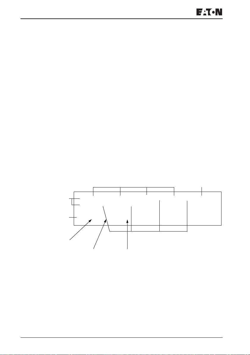
Wiring with EZ800
Circuit diagram display
In the EZ800 Control Relay circuit diagram, contacts and coils
of relays are connected up from left to right - from the contact
to the coil. The circuit diagram is created on a hidden wiring
grid containing contact fields, coil fields and circuit
connections. It is then wired up with connections.
• Insert contacts in the four contact fields. The first contact
field on the left is automatically connected to the voltage.
• Insert the relay coil to be controlled together with its function
and designation in the coil field. The coil designation
consists of the coil name, coil number and function block
from the function designation. The coil function defines the
method of operation of the coil.
• Every line in the circuit diagram forms a rung. With the
EZ800 Control Relay up to 256 circuit connections can be
wired in a circuit diagram
Contact fields (1 to 4) Coil field (5)
Circuit
Status line
Number of the
circuit
I 01----I 02----CP01GT---------Ä Q 01
Q 01----HY01Q1k''''''' ''''''' ''''''''
''''''' ''''''' ''''''' ''''''' ''''''''
L: 1 C:1 B:____
Circuit
Number of the
field in the
Amount of free
memory in bytes
circuit
For more information visit: www.EatonElectrical.com
MN05013004E96
 Loading...