

Page 1

Sonic® 1200S/HR Ultrasonic Flaw
Detector
User’s Manual
PN 7720044, PN 7720066 — March 2006
Page 2

In accordance with European Directive 2002/96/EC on Waste Electrical and Electronic
Equipment, this symbol indicates that the product must not be disposed of as unsorted
municipal waste, but should be collected separately. Refer to your local Olympus NDT
distributor for return and/or collection systems available in your country.
Copyright © 2006 by Olympus NDT. All rights reserved.
No part of this manual may be reproduced or transmitted in any form or by any means,
electronic or mechanical, including photocopying, recording, or by any information
storage and retrieval system, without the written permission of Olympus NDT, except
where permitted by law. For information, contact: [email protected].
Panametrics, Panametrics-NDT, and the Panametrics-NDT logo are trademarks of
Panametrics Inc.
Other product names mentioned in this document may be trademarks of their
respective companies, and are mentioned for identification purposes only.
Printed in the United States of America.
Page 3

Warranty
The Sonic 1200S/HR has been designed and manufactured as a high quality instrument.
Inspect the unit thoroughly upon receipt for evidence of external or internal damage that may
have occurred during shipment. Notify the carrier making the delivery immediately of any
damage, since the carrier is normally liable for damage in shipment. Preserve packing
materials, waybills, and other shipping documentation in order to establ ish damage claims.
After notifying the carrier, contact Olympus NDT
claims, and provide replacement equipment, if necessary.
Olympus NDT guarantees the Sonic 1200S/HR to be free from defects in materials and
workmanship for a period of one year (twelve months) from date of shipment. This warranty
only covers equipment that has been used in a proper manner as described in this instruction
manual and has not been subjected to excessive abuse, attempted unauthorized repair, or
modification. DURING THIS WARRANTY PERIOD, Olympus NDT LIABILITY IS
STRICTLY LIMITED TO REPAIR OR REPLACEMENT OF A DEFECTIVE UNIT AT ITS
OPTION. Olympus NDT does not warrant the Sonic 1200S/HR to be suitable of intended use,
or fitness for any particular application or purpose. Olympus NDT accepts no liability for
consequential or incidental damages including damage to pro perty and/or personal injury. In
addition to our standard one year warranty, Olympus NDT also offers an optional two year
warranty (call for further details).
TM
so that we may assist in the damage
This warranty does not include transducers, transducer cables, or battery. The customer will
pay shipping expense to the Olympus NDT plant for warranty repair; Olympus NDT will pay
for the return of the repaired equipment. (For instruments not under w arranty, the customer
will pay shipping expenses both ways.)
In this manual, we have attempted to teach the proper operation of the Sonic 1200S/HR
consistent with accepted flaw detection techniques. We believe the procedures and examples
given are accurate. However, the information contained herein is intended solely as a teaching
aid and should not be used in any particular application without independent testing and/or
verification by the operator or the supervisor. Such independent verification of procedures
Warranty iii
Page 4

become more important as the criticality of the application increases.
For these reasons, we make no warranty, expressed or implied, that the techniques, examples,
or procedures described herein are consistent with industry standards nor that they will m eet
the requirements of any particular application. Olympus NDT expressly discl aims all implied
warranties of merchantability and of fitness for any particular application.
Olympus NDT reserves the right to modify all products without incurring the responsibility for
modifying previously manufactured products. Olympus NDT does not assume any li ability for
the results of particular installations, as these circumstances are not within our control.
THE WARRANTIES SET FORTH HEREIN ARE EXCLUSIVE AND ARE IN LIEU OF
ALL OTHER WARRANTIES WHETHER STATUTORY, EXPRESS, OR IMPLIED
(INCLUDING WARRANTIES OF MERCHANTABILITY AND FITNESS FOR A
PARTICULAR PURPOSE, AND WARRANTIES ARISING FROM COURSE OF DEALING
OR USAGE OR TRADE).
iv Warranty
Page 5

Table of Contents
Warranty and PowerLink™
1 Preparation for Operation............................................................................. 1
1.1 Unpacking the Sonic 1200S/HR ........................................................................................ 4
1.2 Sonic 1200S/HR Packages................................................................................................. 5
1.3 Sonic 1200S+/HR+ Packages ............................................................................................ 8
1.4 Optional Accessories........................................................................................................ 11
1.5 Initial Inspection Checklist..................................... .......................................................... 11
1.6 Power Requirements ........................................................................................................ 12
1.7 Ni-MH Battery Characteristics......................................................................................... 14
1.8 Li-Ion Battery Characteristics.......................................................................................... 15
1.9 Charging the Ni-MH/Li-Ion Battery................................................................................ 16
1.10 Operating Environment................................... ... ............................................................. 20
2 Technical Data............................................................................................... 21
3 FastBreak Operation.................................................................................... 29
3.1 Getting Started with FastBreak Operation........................................................................29
3.2 Ready................................................................................................................................ 29
3.3 Operating Menu Structure................................................................................................ 30
3.4 Set..................................................................................................................................... 31
4 Control Descriptions..................................................................................... 35
4.1 Instrument Controls........................................................... ............................................... 36
4.2 Power Button.....................................................................................................................37
4.3 Displays............................................................................................................................ 37
4.4 Soft Keys.......................................................................................................... ................ 39
4.5 INC/DEC Arrow Keys......................................................................................................40
4.6 Main Menu Keys.............................................................................................................. 40
Table of Contents
Page 6

4.7 Enter Key...........................................................................................................................42
4.8 Print Key........................................... ................................................................. ............... 42
4.9 SmartKnob™.................................................................................................................... 42
4.10 RCV and XMIT BNCs .................................................................................................... 42
4.11 Pulser Menu......................................................................................................... ............ 43
4.12 Receiver Menu.............................................................. ....................................................43
4.13 Range Menu..................................................................................................................... 44
4.14 Gate 1 Menu .................................................................................................................... 45
4.15 Gate 2 Menu .................................................................................................................... 46
4.16 Thickness Menu............................................................................................................... 47
4.17 Angle Menu................................ ......................................................................................48
4.18 DAC Menu...................................................................................................................... 49
4.19 Main Menu ............................................ .......................................................................... 50
4.20 SPCL Menu ......................................................... ............................................................ 51
4.21 Program Sub-Menu ......................................................................................................... 54
4.22 Report Form Sub-Menu.................................. ................................................................. 55
4.23 Clock Sub-Menu................................. .............................................................................. 56
4.24 A-scan Sub-Menu............................................................................................................ 57
4.25 A-scan Attribute Sub-Menu ............................................................................................ 58
4.26 Data Sub-Menu................................ ................................................................. ............... 59
4.27 New Block Editor..................................... ....................................................................... 60
4.28 Block Review Sub-Menu .................................................................................................61
4.29 Text Editor................................................ ................................................................. ...... 62
4.30 Instrument Reset.............................................................................................................. 63
5 Applications................................................................................................... 65
5.1 Pulse-Echo Contact Thickness Testing ............................................................................ 65
5.2 Dual Transducer Thickness Testing................................................ ...................................74
5.3 Delay Line Thickness Testing .................................... ...................................................... 87
5.4 Shear Wave (Angle Beam) Testing .................................................................................. 98
5.5 Distance Amplitude Correction (DAC) Testing ............................................................. 112
6 Internal Datalogger..................................................................................... 119
6.1 Introduction .................................................................................................................... 119
6.2 Creating a New Block .....................................................................................................120
6.3 Selecting a Block................................. ........................................................................... 121
6.4 Storing Readings into Memory ...................................................................................... 121
6.5 Selecting Locations and Reviewing Readings ............................................................... 122
6.6 Clearing Readings .......................................................................................................... 122
Page 7

6.7 Clearing a Block............................................................................................................. 123
6.8 Deleting a Block........................ .................................................................... ................. 124
6.9 Deleting All Blocks.................................................................................................. ...... 124
7 Computer Interface .................................................................................... 127
7.1 Description..................................................................................................................... 127
7.2 RS-232 Communication .................................................................................................128
7.3 Modes of Operation........................................................................................................ 130
7.4 Command Strings........................................................................................................... 130
7.5 Status Reporting............................................................................................................. 131
7.6 RS-232 Command Set................................... ................................................................. 132
7.7 Examples........................................................................................................................ 143
Documentation Comments
Table of Contents
Page 8

Page 9

1. Preparation for Operation
What’s in this section?
Introduction to PowerLink™
• 1.1 Unpacking the Sonic® 1200S/HR
• 1.2 Sonic
• 1.3 Initial Inspection Checklist
• 1.4 Power Requirements
• 1.5 Ni-MH Battery Characteristics
• 1.6 Li-Ion Battery Characteristics
• 1.7 Charging the Ni-MH / Li-Ion Battery
• 1.8 Operating Environment
Introduction to PowerLink™
®
1200S/HR Optional Accessories
The PowerLink™ feature enables the Sonic
NDT PowerLink transducer type and provides the capability to modify selected instrument
parameters for program storage and recall. PowerLink has a separate screen with a sign-on
®
1200S/HR instrument to recognize a Olympus
Preparation for Operation 1
Page 10
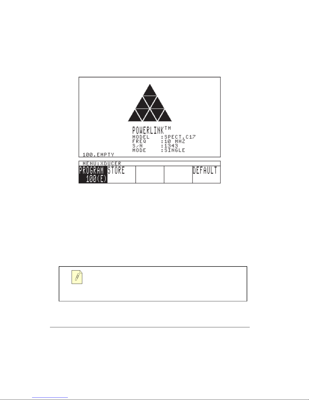
message and menu structure (as shown).
Each PowerLink transducer is programmed at the factory to identify itself by model,
frequency, serial number and type. The operator may select the factory default setup for each
transducer type in the event that an instrument setup has not been associated with that
transducer.
The stored program feature is tied into the program store and recall features of the instrument.
This makes stored programs associated with transducers look the same to the operator as other
stored programs.
Before any stored transducer programs can be recalled, a Olympus NDT transducer must be
connected to the instrument and identified. Multiple programs are associated with each
transducer and the operator is allowed to select from the programs stored.
When a transducer linked through PowerLink is removed and replaced with
another transducer, the Sonic
®
1200S/HR instrument MUST be recalibrated, or the
new transducer relinked before testing.
2 Chapter 1
Page 11

PowerLink™ Connection
®
After connecting a Olympus NDT transducer to your Sonic
1200S/HR instrument, touch and
hold the transducer to the PowerLink contact disc on your EL/LCD display for approximately
4 seconds, or 2 beeps. If contact is not
maintained for the proper amount of time, the screen
will show the PowerLink display with N/A parameters. In this case, try again, until the
PowerLink connection is complete and parameters are displayed.
Menu Description
• ModelTransducer Model
• FrequencyTransducer Nominal Frequency
• S/NSerial Number (stamped on the front of the transducer)
• ModeSingle or Dual
• Program Name and Date Stamp - Program num ber, optional operator-entered description,
and date stamp. The stored program number is shown in the PROGRAM softkey menu
box.
Program
This line displays the program storage location/transducer setup, which is to be stored,
recalled, or erased. Rotating the SmartKnob
™
will cycle through the storage locations
associated with the identified transducer. If no stored locations are associated with the
identified transducer, the number of the next empty storage location will be displayed.
Store/Recall
Instrument settings associated with the identified transducer are stored to or recalled from the
selected program location. If the location is empty, the operator is allowed to store the
instrument setup. Whenever a transducer setup is recalled, the current instrument settings are
overwritten and cannot be recovered unless the setup was previously saved.
Erase
Allows the operator to erase the selected transducer setup. This needs to be done only if the
storage location is to be reused. An ENTER confirmation will be required from the operator
before the program location is cleared. An erased location cannot be recovered.
Name
Allows the operator to enter a name of up to 26 characters to identify the setup. Only program
locations which are not empty may be named.
Preparation for Operation 3
Page 12

Default
Restores the factory default instrument setup and changes the PULSEWIDTH, FREQUENCY,
and MODE parameters of the receiver in accordance with the identified transducer parameters.
The PowerLink menu may be exited at any time without changing instrument setups by
pressing any menu key on the main keypad. When recalling default setups for an angle b eam
transducer, the operator will be sent to the ANGLE menu on return from the PowerLink menu.
When recalling the default setting from a nonangle beam transducer, the operator will be
returned to the RCVR menu on exit from PowerLink.
1.1 Unpacking the Sonic 1200S/HR
All cartons should be opened and inspected upon receipt. The cartons and contents should be
inspected for any signs of damage that may have occurred during shipment. If damage is noted,
contact the carrier and retain the damaged shipping materials until an inspection can be
performed by a representative of the carrier. With the exception of the UBC (universal battery
charger) and external accessories, all Sonic
shipped. Check the contents of the carton or cartons against the Packing List to ensure that all
accessories ordered have been received.
®
1200S/HR options are installed before the unit is
4 Chapter 1
Page 13
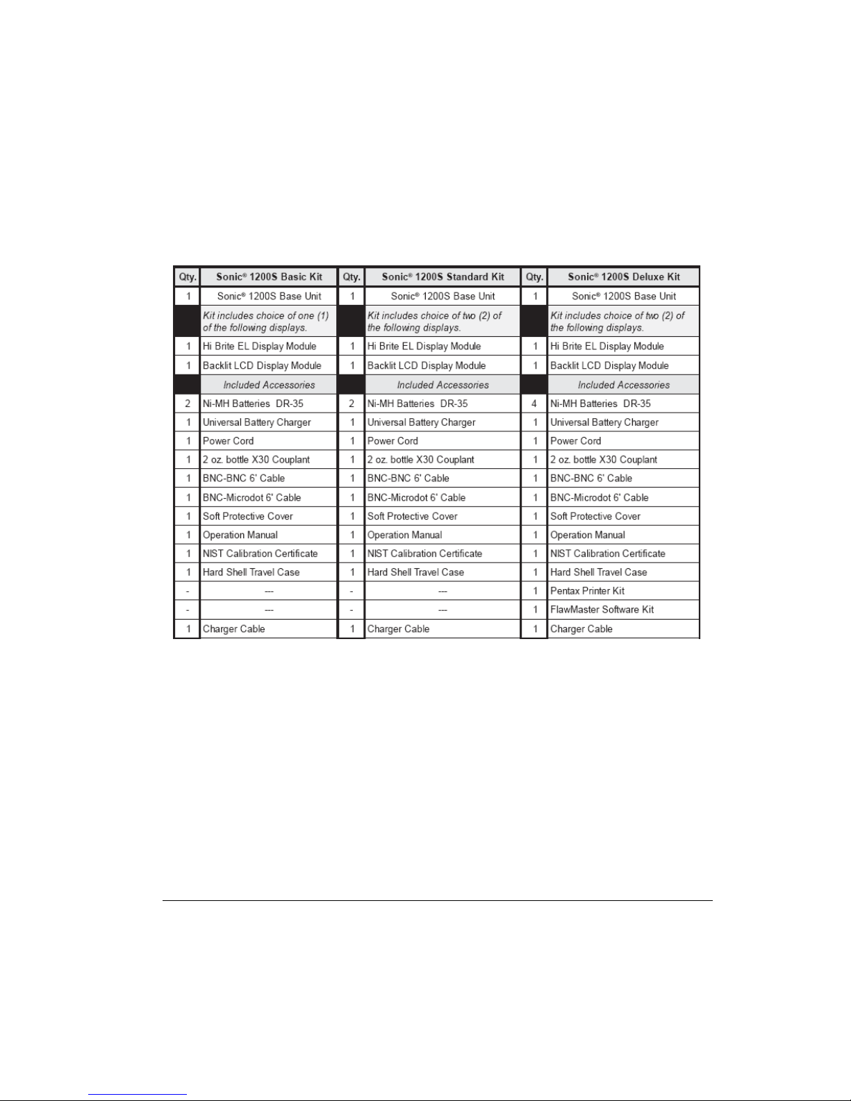
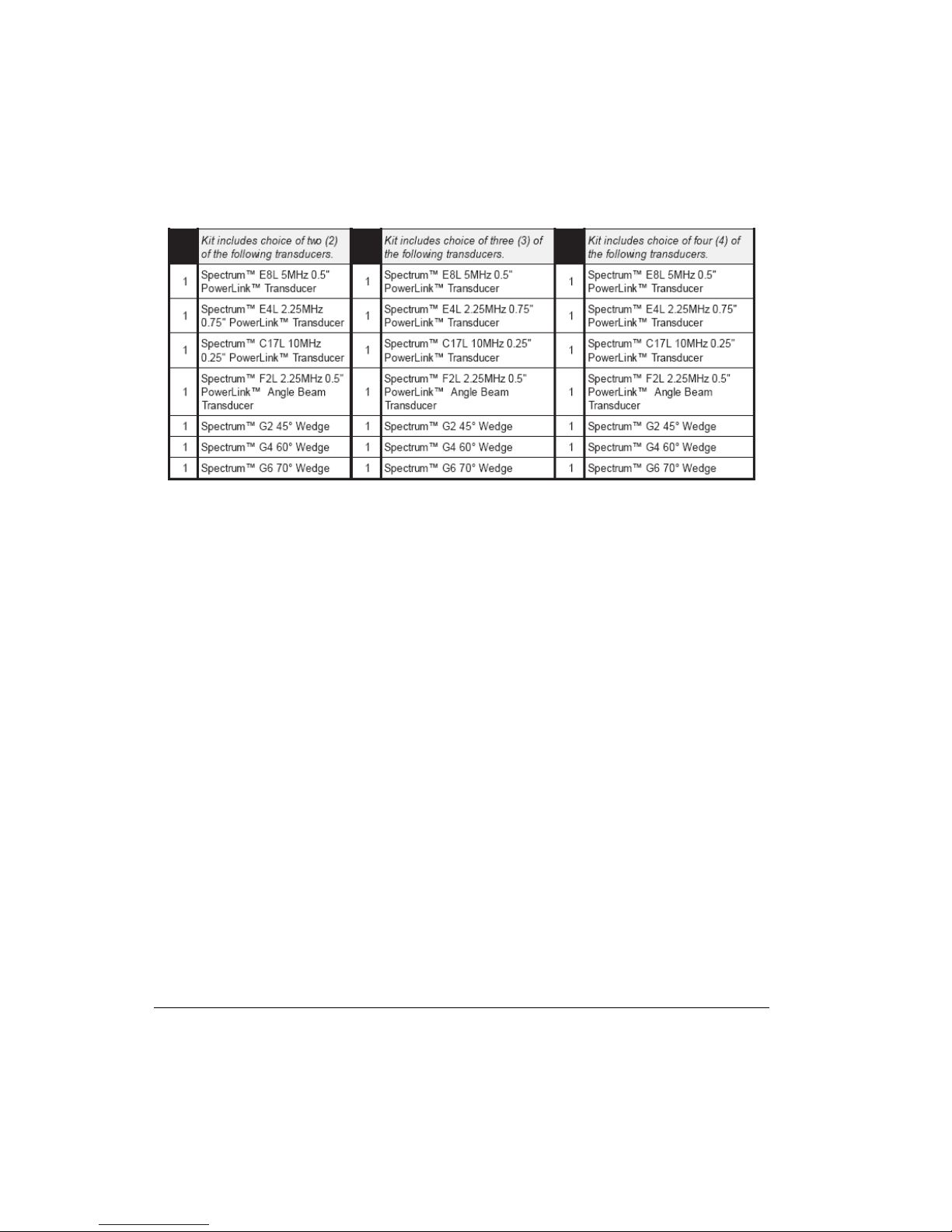
1.2 Sonic® 1200S/HR Packages
1.2.1 Sonic
®
1200S Packages
Preparation for Operation 5
Page 14
6 Chapter 1
Page 15
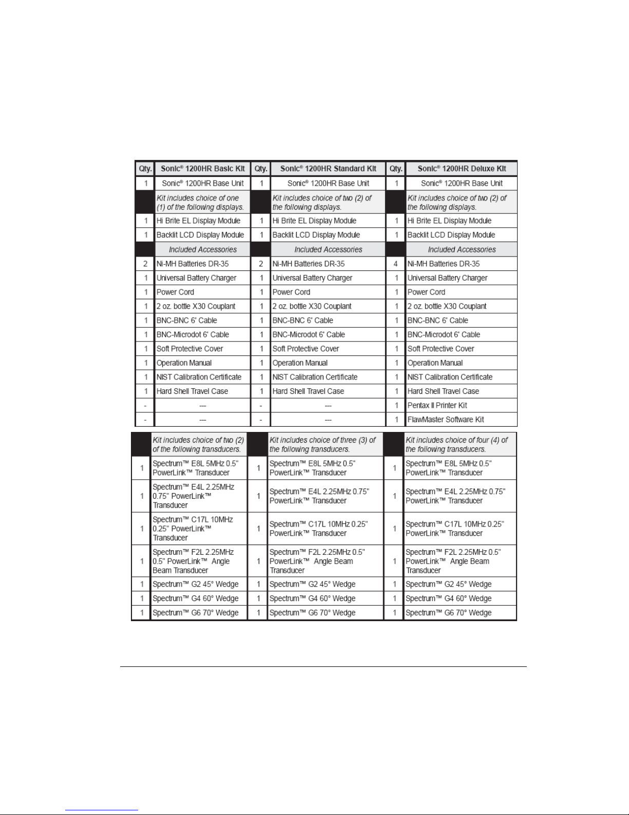
1.2.2 Sonic
®
1200HR Packages
Preparation for Operation 7
Page 16
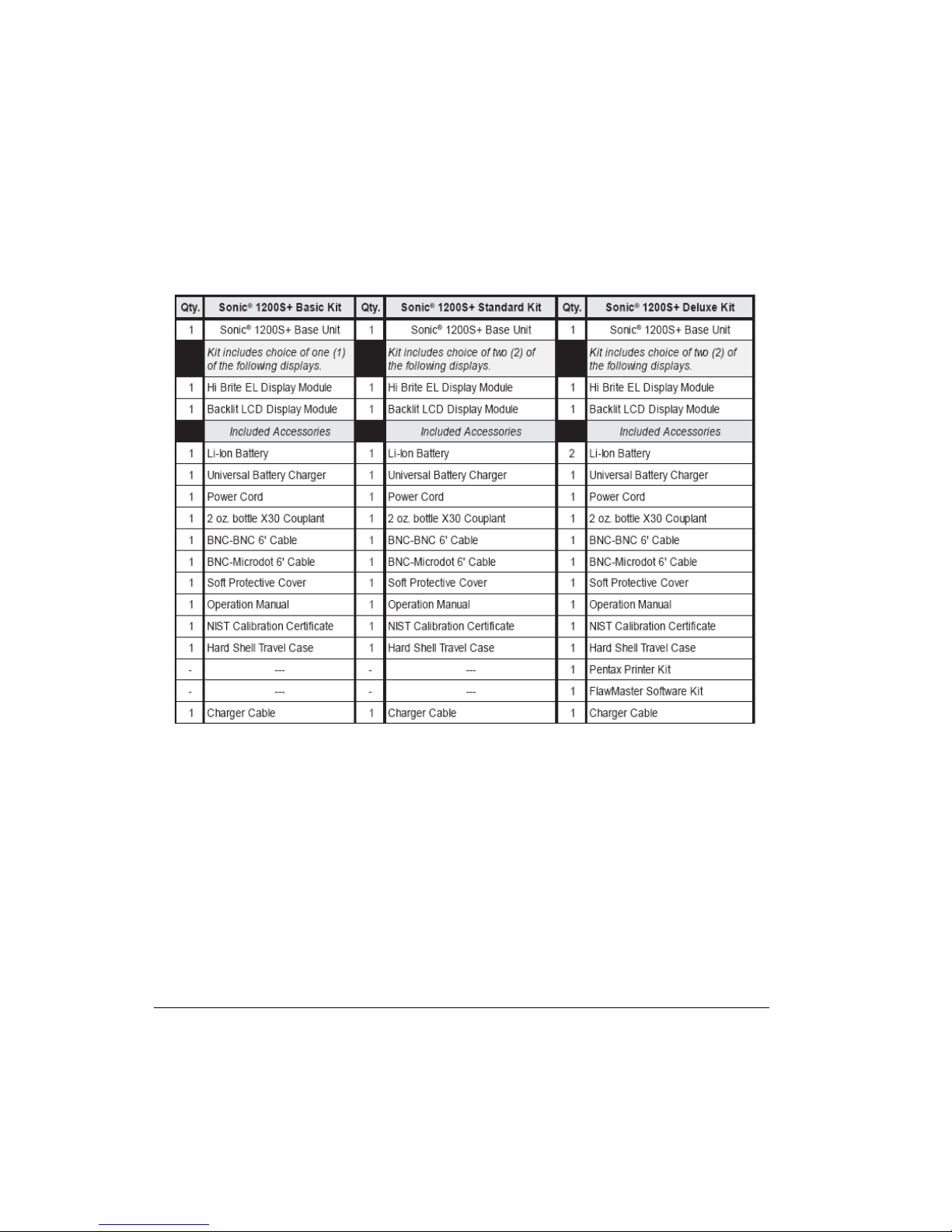
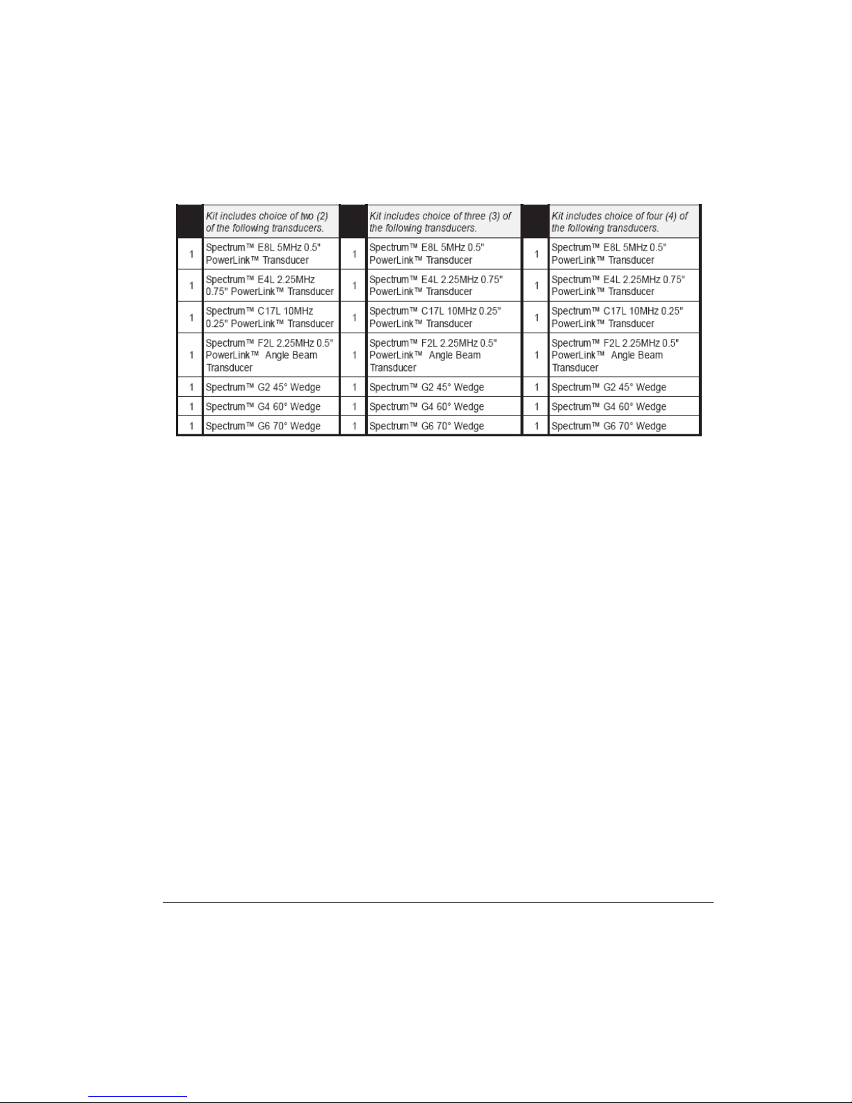
1.3 Sonic® 1200S+/HR+ Packages
1.3.1 Sonic® 1200S+ Packages
8 Chapter 1
Page 17
Preparation for Operation 9
Page 18
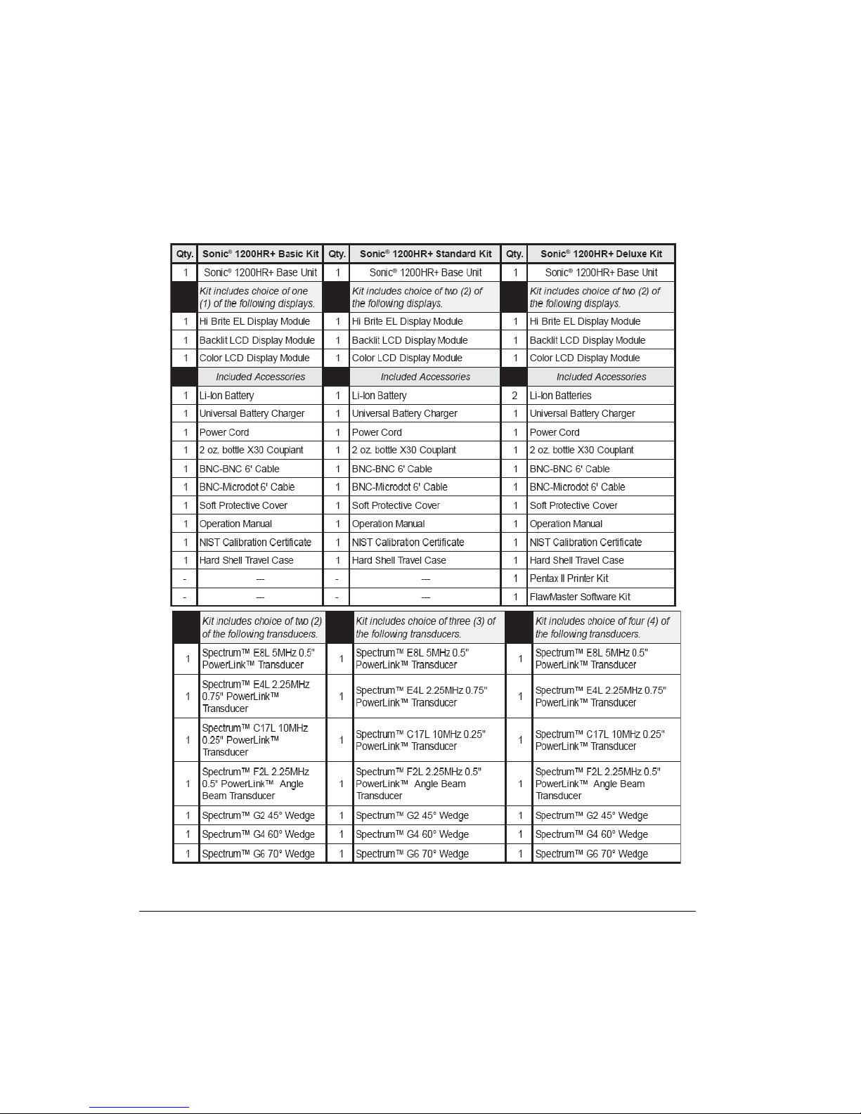
1.3.2 Sonic® 1200HR+ Packages
10 Chapter 1
Page 19
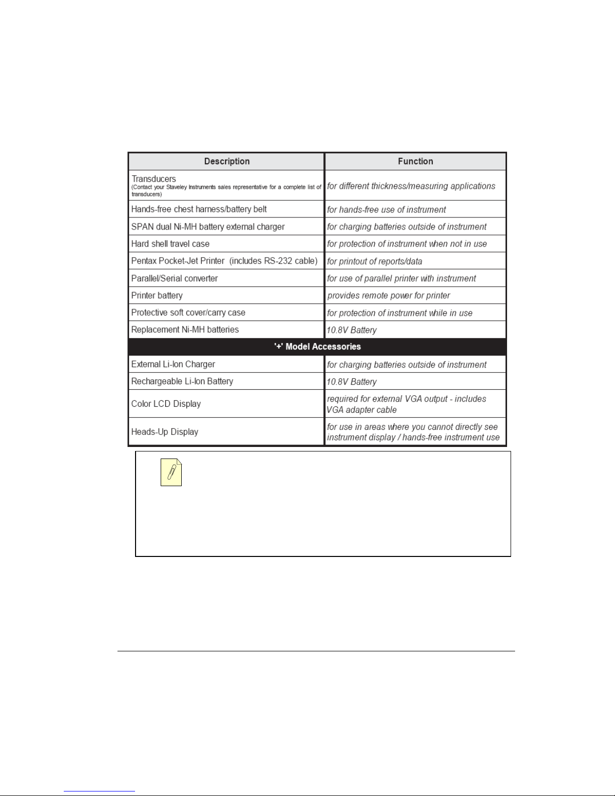
1.4 Optional Accessories
Hands-free Chest Harness/Battery Belt - This accessory is designed to hold the
weight of the Sonic
equipment and it’s accessories. Specifically, the pouch on the chest harness is
designed to hold the DR-35 battery sled, which adds two b atteries to the system to
extend field operation time. THE CHEST HARNESS IS NOT DESIGNED TO
SAFELY SUPPORT THE WEIGHT OF THE USER IN ANY SITUATION!
®
/Nortec®/BondMaster 1200 series of nondestructive test (NDT)
1.5 Initial Inspection Checklist
After the Sonic® 1200S/HR has been unpacked and the contents of the carton have been
checked against the packing list, a visual inspection and a basic operation test should be
Preparation for Operation 11
Page 20

performed.
• Cosmetic or structural damage?
• Istrument Power “On”
•Power On Self Test
• EL/LCD Sign On Message displays?
1.6 Power Requirements
As a fully portable inspection instrument, the Sonic® 1200S/HR relies on two nickel-metal
hydride (Ni-MH) batteries (one Lithium Ion (Li-Ion) battery on ë+’ models) as the primary
source of power. The battery compartment is located at the rear of the unit and is conveniently
accessed by loosening the two quick release screws and removing the battery cover.
Li-Ion
RCV XMT
Top of Instrument
Ni-MH
RCV XMT
Figure 1-1: Battery Cover Locations
The batteries provided with the Sonic
®
1200S/HR instrument are small, lightweight, portable,
and capable of delivering long service life between recharges or battery replacement.
A Universal Battery Charger (UBC) unit is pro vided wi th the S onic
®
1200S/HR for recharging
the batteries while in the instrument or external battery pack and allowing the Sonic
1200S/HR to be operated from AC line power. The UBC unit auto senses 90-264 VAC, 47 to
12 Chapter 1
®
Page 21

63 Hz power.
®
The condition of the batteries used in the Sonic
1200S/HR is monitored by the charger. Fully
discharged Ni-MH batteries will require approximately 8 hours for a complete charging cycle
(4 hours for each battery), while Li-Ion batteries will require approximately 6 hours. The
charger will not charge batteries which are too hot, too cold, or too deeply discharged.
For optimum performance:
• Refer to the manual that came with your instrument or charger for charging instructions.
• When you charge your battery for the first time, your charger may indicate that charging is
complete after just 10 to 15 minutes. This is normal and can happen with all rechargeable
batteries when first charged. Simply remove the battery and then repeat the charging
procedure.
• Upon first use, or after prolonged periods of storage, you may need to charge and
discharge your battery two or three times before obtaining optimum performance.
• It is best to charge the battery at room temperature ranging between 59°F (15°C) and 86°F
(30°C).
• It is normal for the battery to become warm during charging or after use.
• It is not necessary to fully discharge your battery before charging. You can top-off the
charge at any time.
• A charged battery will gradually lose its charge if left in storage. We therefore suggest that
you top-off the charge before use.
• Remove your battery from the equipment, charger or AC adapter when not in use. Store at
room temperature in a dry place.
To avoi d damage to the battery:
• Do not drop the battery or subject it to mechanical shock.
• Use the battery only with equipment that specifies its use.
For safe operation:
• Do not disassemble or attempt to open the battery under any circumstances.
• The battery can explode, leak, or catch on fire if heated or exposed to fire or high
temperatures.
• Do not short circuit the battery by directly connecting the metal terminals (+, -). Be certain
that no metal objects such as coins, paper clips, etc., touch the terminals.
• Only use the charger recommended by the device manufacturer.
Preparation for Operation 13
Page 22
Note that internal memory batteries should be changed as a preventative maintenance feature
every two (2) years.
It is recommended that you refrain from operating the instrument while recharging
fully discharged batteries. The charge may be incomplete and thus activate the temperature
fault indicator — as a result, battery life and instrument run time may be shortened
significantly. If the indicator is activated, shut off the instrument and disconnect the
instrument from the charger. Allow the batteries to cool, then reconnect the charger to the
instrument to start a new charge cycle.
1.7 Ni-MH Battery Characteristics
• Higher capacity - up to 40% longer run time than ordinary nickel-cadmium bat teries of
equivalent size
• Fast Charge - approximately 4 - 6 hours
• Long cycle life - up to 500 charge/discharge cycles
• Temperature Range (charging) - 32°F to 104°F (0°C to 40°C)
• Temperature Range (operating) - 32°F to 122°F (0°C to 50°C)
• Temperature Range (storage) - -4°F to 122°F (-20°C to 50°C)
• Environmental friendliness - 0% cadmium, no disposal problems
• Size L x W x H - 8.5 x 2.1 x 0.7 in. (215 x 53 x 19 mm)
• Weight - 18.4 oz. (515 g)
• Nominal Voltage - 10.8V
• Rated capacity - 3.8 Ah nominal
• Hours of Operation - 10+ hours with EL display or Monochrome LCD display
Narrow Keyway
+
2" Wide
-
14 Chapter 1
Ni-MH Battery
Page 23

1.8 Li-Ion Battery Pack Characteristics
• Higher capacity - up to 60% longer run time than ordinary Ni-MH batteries of equivalent
size
• Fast Charge - approximately 4 - 6 hours
• Long cycle life - up to 300 charge/discharge cycles
• Temperature Range (charging) - 32°F to 104°F (0°C to 40°C)
• Temperature Range (operating) - -4°F to 140°F (-20°C to 60°C)
• Temperature Range (storage) - -4°F to 122°F (-20°C to 50°C)
• Environmental friendliness - 0% cadmium, no disposal problems
• Size L x W x H - 8.5 x 2.3 x 0.9 in. (215 x 59 x 23 mm)
• Weight - 17.6 oz. (493 g)
• Nominal Voltage - 10.8V
• Rated capacity - 6.6 Ah nominal
Preparation for Operation 15
Page 24
• Hours of Operation - 8+ hours with EL display, Monochrome LCD, or Color LCD display
Wide Keyway
+
-
2¼" Wide
Li-Ion Battery
Fully charge battery before first use. Instrument run time is affected by
variables such as: quality of charge, age of battery, and display type. The battery
charge indicator on the display is an estimation of expected run time. Instruments are
equipped with a circuit that shuts off power prior to full discharge. Battery life is
affected by: number of charge/discharge cycles, storage conditions, temperature, and
use. Batteries stored for extended periods of time (mon ths/years) without use may no
longer recharge. Under normal use Nickel-Metal Hydride (NiMH) batteries last
approximately 500 charge/discharge cycles, while a Lithium-Ion battery will last
approximately 300 cycles. Expect to change the batteries after 1 year of heavy use or 3
years of light use under normal conditions. Batteries must be disposed of in
accordance to local law or returned to Olympus NDT Instruments. Olympus NDT
Instruments does not warranty batteries, due to op erating conditions beyo nd Olympus
NDT’s control affecting battery life.
Dual Ni-MH battery run time for the Sonic
is at least 10 hours. Dual Ni-MH battery run time for the Sonic
®
1200S/HR with the LCD module
®
1200S/HR with the
electroluminescent (EL) display module at 100% intensity, is at least ten (10) hours.
1.9 Charging the Ni-MH/Li-Ion Battery Pack
Proper charging of the Ni-MH/Li-Ion battery packs is critical for overall life and performance.
The Universal Battery Charger (UBC) will charge either the Li-Ion battery used in the single
battery instruments or both Ni-MH batteries in the dual battery instruments. Th e selection of
charging system is made by the detachable cable to instrument connection. The two instrument
categories have very different, non-interchangeable connectors to prevent an incorrect
16 Chapter 1
Page 25

connection. Note that the UBC to instrument cables are detachable and replaceable as catalog
items.
The charger also functions as a battery eliminator to operate the instrument from the AC power
source. Batteries do not have to be installed to operate the instrument from AC. When operated
from the UBC without a battery installed in the instrument, disregard any battery charge status
indications from the UBC charge indicator. The instrument can be operated while a Li-Ion
battery is being charged, but is not recommended while charging Ni-MH batteries.
1.9.1 UBC Specifications
Power Requirements: 100-240 volts, 47 to 63 Hz.
The UBC contains an internal fuse.
Nickel Metal Hydride battery charging system: Sequentially charges two DR-35 style (Ni-
MH) batteries. Charges at approximately 1 ampere rate. A pair of 3.8 AH batteries take about 8
hours to fully charge.
Lithium Ion battery charging system: Charges one Li-Ion battery . Char ges at approximately 1.5
ampere rate. A 6.6 AH battery charges in approximately 6 to 8 hours.
Temp erature range: Batteries should be charged between 40° to 100° F (4° to 38° C) for best
results. If the batteries become too hot, the battery charger will terminate the charging process.
If the batteries are being charged while using the instrument, the heat from normal operation of
the instrument may cause the battery charger to terminate the charging process before the
batteries are fully charged.
To start a charge cycle, the charger can be reset by disconnecting and reconnecting either the
instrument or AC power to the UBC.
1.9.2 Charger Status Indicators
The charger status is indicated by a red/green LED lamp.
The light may blink red or green for a few seconds when first connected to either AC power or
an instrument. It will then light steady red as the charging process starts. This is normal as the
circuits initialize. If a problem is detected during charging, the light will blink red. Reset the
charger by disconnecting the AC power for a few seconds and re-connect. If the problem
persists, service is required.
Preparation for Operation 17
Page 26

1.9.3 Charger Operation Instructions
1. Connect the UBC to a source of AC power.
2. Connect either the single battery Li-Ion or dual Ni-MH cable to the instrument and
charger.
3. Ni-MH batteries: The red charging indicator will light, indicating that the batteries are
charging. The charger will charge one battery and automatically switch to the second
battery when the first is charged. The indicator will turn green when both batteries are
charged. If only charging one battery, the green charge complete indicator will not light.
The red charging lamp will go out when the battery is charged. Ni-MH batteries generate
heat while in use, especially during charging. This heat, added to that generated by the
instrument, can cause the charger to terminate the charge cycle before the batteries are
fully charged. It is not recommended that NiMH batteries be charged while operating the
instrument. This is not due to power supply capacity, but heat build up within the
instrument.
4. Ni-MH batteries receive a continuous trickle charge whenever they are connected to the
UBC. If the instrument is being used on AC power for long periods of time, the batteries
should be removed from the instrument. They should be re-installed and recharged and
then removed at regular intervals to keep them fresh. 30 to 60 day intervals are
recommended.
5. Lithium-Ion batteries: The red charging indicator will light, indicating that the batteries
are charging. The indicator will turn green when the battery is charged.
6. The charger circuits can be reset if a problem occurs by disconnecting either the AC power
for at least 15 seconds or the UBC to instrument cable (either end) and then re-connecting.
Li-Ion batteries are sensitive to over charge. For this reason, the full charge detection
system is very sensitive and may shut off the charging process before the charge is
complete. If this happens, reset the charger. During use, the UBC case will become warm.
7. The charger is designed to shut off after a Li-Ion battery is fully charged (the instrument
power is always available). It does not provide a maintenance charge, because Li-Ion
batteries can be damaged by trickle charging. To recharge a Li-Ion battery, reset the
charger by either disconnecting the AC supply or instrument for a few seconds to reset the
charger circuit. Li-Ion batteries have a long shelf life and should only require recharging
after many months of storage if not used.
1.9.4 Battery Safety
Old batteries that will no longer deliver satisfactory service shoul d be disposed of in a legal
and environmentally friendly manner. In the USA, call 1-800-8BATTERY for the nearest
battery recycle center. If there is no convenient battery recycle center, the batteries may be
returned to Olympus NDT Instruments for proper disposal.
18 Chapter 1
Page 27

No battery should be disposed of by fire or abused by puncturing its case or disassembled. All
batteries contain potentially hazardous chemicals, however neither Ni-MH or Li-Ion batteries
contain lead, cadmium or mercury.
Lithium-Ion batteries contain an internal safety circuit. Both Nickel-Metal Hydride and
Lithium-Ion batteries contain internal fuses. If this fuse blows or the safety circuit shuts off the
battery, the battery is no longer fit for service. The internal safety circuits are not serviceable.
Olympus NDT Instruments purchases batteries from reputable vendors. Although Olympus
NDT Instruments tests and qualifies the batteries for use in Olympu s NDT prod ucts, Olym pus
NDT can not guarantee that batteries obtained from other sources will be satisfactory or that
Olympus NDT supplied batteries will work in non Olympus NDT products. The Universal
Battery Charger is designed to work with Olympus NDT equipment only.
1.9.5 Battery Characteristics
Most batteries will not deliver their full charge on first use or after extended storage. Use them
until the instrument shuts off after full discharge (automatic low battery shut off) and recharge.
This will recondition the battery. This is especially prudent with Ni-MH batteries.
The battery is considered by the manufacturer to be beyond its service life when it delivers less
than 80% of its rated capacity. A Ni-MH battery should have a life expectancy of 500
charge/discharge cycles and Li-ion batteries, 300 cycles. These specifications are obtained
under laboratory conditions and real world usage will be different.
Battery life will be prolonged if they are not subjected to harsh temperatures, either hot or cold,
and stored in a charged condition. Ni-MH batteries should be recharged periodically. They
should not be left in the instrument when not being used over extended time.
Batteries have reduced capacity at low temperatures. Exact percentages are not specified but
operation below freezing is not recommended.
Preparation for Operation 19
Page 28

1.9.6 UBC Spare Parts
noitpircseDtraP rebmuNtraP
)CBU(regrahCyrettaBlasrevinU 3512259
NID 9222219
wopCA 9595020
taBedirdyHlateMlekciN53RD 7449110
yret
yrettaBnoImuihtiL 1549110
)023CEIotgnorpeerhtSU(elbacre
)023CEIotpma31KU(elbacrewopCA 9512220
)023CEIotrotcudnoc3nailartsuA(elbacrewopCA 5422220
)yrettabnoI-iL(stnemurtsniyrettabelgnisrofelbacrotcennoc
)yrettabHM-iN(stnemurtsniyrettablaudrofelbacrehcsiFnip7 0322219
1.10 Operating Environment
The Sonic® 1200S/HR is designed as a portable instrument and, as such, requires no special
site preparation before operation. When operating, the in strument should be firmly support ed
to prevent damage due to a fall. The unit should be protected as much as possible from water or
chemical splashes, rapid temperature changes, and should be operated away from large
electrical equipment that may interfere with the operation of internal circuitry.
20 Chapter 1
Page 29

2. Technical Data
Pulser:
Type: Square wave.
Pulse Width: 30 to 1000 ns (HR: 15 to 500 ns
Accuracy: ±10% or 10 ns, whichever is greater.
Pulse Voltage: Selectable 300 or 150 volts.
Accuracy: +10/-15%.
Rise Time: < 15 ns.
Fall Time: < 60 ns damping 200 ohms. < 20 ns damping 50 ohms.
Damping: Selectable 25, 50 or 200 ohms.
Modes: Selectable single, dual, or through transmission.
Receiver:
Frequency Band: 0.3 to 20 MHz, +/-3 dB nominal.
Gain: 0 to100 dB in wideband, highpass, 10 MHz, and 15 MHz (HR). 0 to 110 dB in 1, 2.25,
and 5 MHz frequency settings.
Accuracy: ±0.5 dB for any 10 dB increment, cumulative errror < ±2.0 dB.
Control: Continuous adjustment in selectable 0.2, 1.0, 2.0, 6.0 or 12dB steps.
T echnical Data 21
Page 30

+dB switch: Selectable 6, 12, 18, or 24 increment.
Accuracy: ±0.5 dB.
Tuning Range: Selectable 1, 2.25, 5, 10, 15(HR) MHz, wideband (0.3-15 MHz), and highpass
(3-20MHz).
Q: 0.9 less than or equal to Q less than or equal to 1.2
Linear Reject: 0 to 80% full screen.
Accuracy: ±0.5%.
Vertical Linearity: ± 2% full screen for 10% to 90% of full screen display.
Dynamic Range:> 34 dB (largest signal = 100% full screen height, smallest signal <= 2% full
screen height).
Sensitivity: Better than 200 µV.
Noise: <15 µV RMS
Display Modes: RF, R F+, RF-, fullwave, halfwave+, halfwave-, filter 1, 2, 3.
Thickness/RF: Thickness measure on live and frozen RF display modes.
DAC: Segmented with 25 operator selected points, segments generated automatically.
Range: 40dB, total of gain and DAC limited to 110dB maximum.
Accuracy: DAC range ±2dB, echo adjustment ±0.5dB.
Slew Rate: 6dB per µs.
Depth: Sum of timebase delay and range up to 400µs.
DAC Display: Selection of multiple curves showing compensation; single curve at signal level
(0 dB); three curves at +6 dB, 0, and -6 dB; four curves at +6 dB, 0, -6 dB, and -14 dB, JIS
curves at +6 dB, 0, -6 dB, and -12 dB, DAC compensated echoes only; single curves with
DAC compensated echoes.
Gates:
Gate Functions: Gate 1 time of flight, amplitude detect ion and flaw alarm. Gate 2 amplitude
detection and flaw alarm, time of flight for echo-to-echo mode.
22 Chapter 2
Page 31

Gate Position:
• Start: 1.16 to 185" (-29 mm to 4694 mm) of steel (-10 to 1600 µs).
• Width: 0.001 to 296" (0.001 mm to 7510 mm) of steel (0.001 to 2560 µs).
• Control: Continuous over full range adjustment.
• Display: Alarm bar indicating position and threshold.
• Accuracy: ±1% of indicated position.
Threshold
• Control: Variable, 5 to 100% of full screen.
• Accuracy: ±1%.
Flaw Alarm
• Logic: Selectable, positive or negative occurrence.
• Indicator: Switchable horn and flashing display indicators.
Peak Detector
• Amplitude: Peak amplitude of gated signal in percent of screen height.
• Accuracy: ±1%.
Analog Output
• Amplitude: Scalable. 1000 mV to 4000 mV with offset
-4000 mV to +4000 mV.
• Accuracy: Greater of 30 mV or 2% of display indication with a 1000 ohm load.
Alarm Output: 3.3 V logic signals (0V = no alarms, 3.3V = alarm condition).
Timebase:
Range
Range: 0.048 to 296" (1.23 mm to 7511mm) of steel (0.418 to 2560µs).
Accuracy: ±1%.
Delay
Range: -1.16 to 185" (-29 mm to 4690mm) of steel (-10 to 1600µs).
T echnical Data 23
Page 32

Accuracy: ±1%.
Velocity: 0.0250 to 0.6000 in/µs (635 to 15240 m/s).
Repetition Rate: 3450Hz maximum limited by range and pulse width settings.
• Control: Selectable in 50Hz steps.
• Accuracy: ± 0.05%.
Horiz. Linearity: ± 1% of full screen.
Thickness:
Range: 0.010" (0.005 HR)-296" (or maximum display range, whichever is smaller).
Resolution: 0.010 (0.000 5 HR) inch when display range is <1.00 inch; 0.5% of d isplay range
when display range is
equal to or greater than 1.00 inch
Distance Output
• Amplitude: Scalable. 1000mV to 4000mV.
• Accuracy: Greater of 30mV or 2% of display indication with a 1000 ohm load.
Modes: Selectable. Start-to-echo, echo-to-echo, autocal start-to-echo, autocal echo-to-echo.
Freeze: Thickness measurements on freeze display mode.
Trig FunctionsAngle beam calculations are performed and displayed, correction for curved
surfaces.
Display: Soundpath, surface distance, and depth from the surface.
Angle: 0° - 90° in 0.1° increments.
Diameter: 0.250" - 100", flat (OFF).
RF Thickness: Thickness measurements in RF display mode.
Alarm Output: 3.3 v logic signals. (0 = no alarms; 2 v = alarm condition)
24 Chapter 2
Page 33

Connector:
Inputs
POWER: Runs the instrument and recharges the battery from an external charger.
I/O
RS232C: DB9P connector, provides bi-directional serial RS232C communication port; port
provides control and reporting of all instrument functions using a terminal or host computer.
Display Features:
Screen Freeze: On command, currently displayed signal is frozen
Waveform Recall: Select and display a stored waveform.
Reference Memory: Waveform recall and active signal displayed position control separate.
Peak Hold: Simultaneous display of peak amplitude waveform and active signal.
Storage: Up to 100 A-Scan waveforms may be stored for future playback or printout.
Control Resolution: Selection of 3 or 4 digit control.
Zoom: Expands gated region under Gate 1 to full display.
Additional Features:
Program Storage: Provides the ability to store up to 100 test setups in nonvolatile memory.
Report Fields: User-defined, 40 character report header; up to 7 user-defined, 40 character
report fields and 26-character labels: and up to 3 user- defined, 26-character report entries may
be downloaded through the RS-232 port, or entered through the report edit function.
Clock, Calendar: Time and date information stored and printed with each waveform.
Instrument ID: Manufacturer name and model printed with each waveform.
Int’l Menu: Selectable languages include English, Spanish, French, and German .
Lemo XMT/RCV: Optional European spec Lemo connectors for transmit and receive
connectors.
T echnical Data 25
Page 34

PowerLink™: Automatic transducer recognition, instrument setup, and report field entry.
A-scan Security: Read-only selection prevents accidental erase of A-scan settings.
General:
Dimensions: 9.5" L x 5.5" W x 3.5" D (241 mm x 140 mm x 89 mm).
Weight:
• 1200S/HR: 6 lbs. (2.7Kg) with batteries installed.
• 1200S/HR+: 4 lbs (1.8Kg) with battery installed.
• 1200HR+: 4.6 lbs (2.09 Kg) with battery installed.
Display (EL): EL (electroluminescent), 3.0" x 3.8" (4.85" diagonal) (77 mm x 97 mm x 122
mm diagonal) active display area. 240 H x 320 pixel display resolution. 72 Hz refresh rate.
HR: EL (electroluminescent), 4.7" x 3.5" (5.7" diagonal) (120 mm x 90 mm x 145 mm
diagonal) active display area. 320 H x 240 v pixel display resolution. 72 Hz refresh rate.
Display (LCD):Monochrome LCD (liquid crystal display), 3.0" x 3.8" (4.8" diagonal), 320 H x
240 V pixel. 72 Hz refresh rate. Backlight is adjustable for different viewing conditions.
Display (Color LCD) : Available as option for 1200S/HR+ and HR+ models. Color LCD
(liquid crystal display), 3.0" x 3.8" (4.8" diagonal), 32 0 H x 240 V pixel. 72 Hz refresh rate.
Backlight is adjustable for different viewing conditions.
Operating Temp:-4° to 140°F (-20° to 60°C)
Storage Temp: -40° to 176°F (-40° to 80°C)
Operating Humidity: 0% to 95% RH.
Power
• DC(2) 10.8V DR35 Ni-MH batteries or (1) 10.8 V Li-Ion battery, depending on model.
• ACExternal. Will recharge the battery pack in approximately 4-6 hours, and run the
instrument simultaneously.
Battery Level: Front panel display. A warning message indicates when there is less than ½ hour
of operating time left.
26 Chapter 2
Page 35

Operating Time: 8 to 10 hours typical at 75°F. The estimated operating time remaining is
indicated by an icon on the status display.
T echnical Data 27
Page 36

28 Chapter 2
Page 37

3. FastBreak Operation
What’s in this section?
• 3.1 Getting Started with FastBreak Operation
•3.2 Ready
• 3.3 Operating Menu Structure
•3.4 Set - Horizontal Screen Calibration-Angle Beam Inspection (10.0 Range)
•3.5 Go - Weld Inspection
3.1 Getting Started with FastBreak Operation
The FastBreak Operation section was created for the more experienced nondestructive testing
(NDT) operator. The intent is to provide a shortcut to instrument operation for the two most
frequently used methods of flaw detection and thickness testing, Angle Beam Weld Inspection
and Dual Element Thickness Measurement. Specific examples are given for 10.0" angle beam
and 0.500" thickness measurements. If your particular appli cation requires another method of
flaw detection or thickness testing, a complete guide of step-by-step applications is provided in
Section 5, Applications.
3.2 Ready
The following controls and menus are required for instrument set-up and calibration. Menus
are activated by pressing the associated menu key. Parameters are selected by pressing the soft
key below the parameter to be adjusted. Parameters may be changed by either rotating the
SmartKnob
TM
or pressing the up and down arrow keys on the display module.
FastBreak Operation 29
Page 38
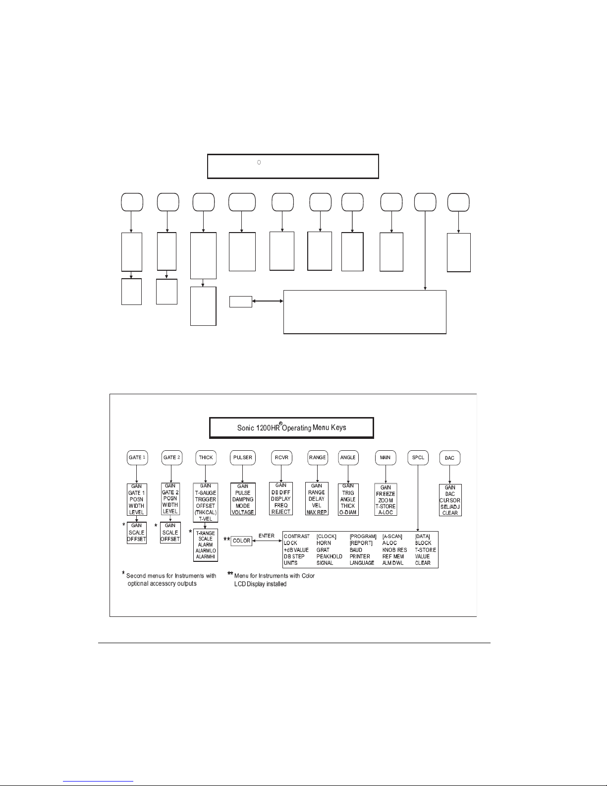
3.3 Sonic® 1200S/HR Operating Menu Structure
1
2
R
Sonic 1200S Operating
Menu Keys
T-GAUGE
TRIGGER
OFFSET
(THKCAL)
T-RANGE
*
ALARMLO
ALARMHI
THICK
GAIN
T-VEL
SCALE
ALARM
GATE
GAIN
GATE 1
POSN
WIDTH
LEVEL
GAIN
*
SCALE
OFFSET
*
Second menus for Instruments with
GATE 2
POSN
WIDTH
LEVEL
*
SCALE
OFFSET
GAIN
GAIN
optional accessory outputs
PULSER RCVR
GAIN
PULSE
DAMPING
MO DE
VOLTAGE
COLOR
**
Menu for Instruments with Color
**
GAIN
DB DIFF
DISPLAY
FREQ
REJECT
ENTER
CONTRAST [CLOCK] [PROGRAM] [A-SCAN] [DATA]
LOCK HORN [REPORT] A-LOC BLOCK
+dB VALUE GRAT BAUD KNOB RES T-STORE
DB STEP PEAKHOLD PRINTER REF MEM VALUE
UNITS SIGNAL LANGUAGE ALM D W L CLE AR
LCD Display installed
RANGE
GAIN
RANGE
DELAY
VEL
MAX R EP
ANGLE
GAIN
TRIG
ANGLE
THICK
O-DIAM
MAINGATE
GAIN
FREEZE
ZOOM
T-STORE
A-LO C
SPCL
DAC
GAIN
DAC
CURSOR
SEL/ADJ
CLEAR
30 Chapter 3
Page 39
3.4 Set — Horizontal Screen Calibration — Angle Beam Inspection
(10.0" range)
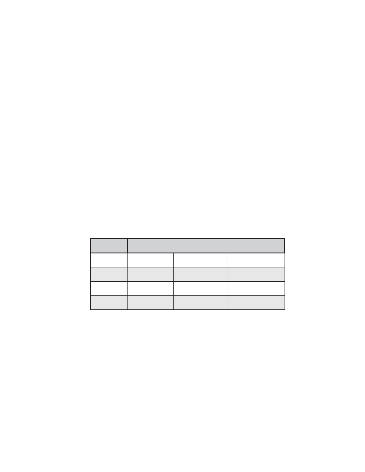
1. Adjust the timebase RANGE and VELocity to 10.0" and 0.1260 in/µs respectively.
2. Set the timebase DELAY to 0.600".
3. Set the PULSER mode to SINGLE.
4. Select RCVR GAIN and FREQuency appropriate for the transducer in use (60 dB is a
good starting point).
5. Choose the RCVR DISPLAY mode which gives the best signal response.
6. Verify the transducer wedge angle and index point.
7. Using a standard block such as IIW Types I or II or the AWS B1 block, calibrate the
screen range as follows:
a) Move the transducer to intercept the calibration reflector on the calibration block.
b) Adjust the timebase DELAY until the first echo falls on the graticule line outlined for
the block in use.
c) Adjust the timebase VELocity until the second display echo falls on the graticule
listed.
d) Repeat until all echoes align with appropriate graticule lines.
KCOLB SNOITACIDNI
-noitcelfeRtsriFnoitcelfeRdnoceSsnoitcelfeRrehtO
1epyTWII )"4(4eniL )"9(9eniL
2epyTWII)"2(2eniL)"4(4eniL
kcolB1B )"1(1eniL )"4(4eniL )"01,"7(01,7seniL
3.4.1 Horizontal Screen Calibration
1. Adjust the timebase RANGE and VELocity to 0.500" and 0.2310 in/µs, respectively.
2. Set the timebase DELAY to 0.400".
3. Set the PULSER mode to DUAL.
4. Select RCVR GAIN and FREQ appropriate fo r the transducer in use (60 dB is a good
starting point).
FastBreak Operation 31
Page 40

5. Choose the RCVR DISPLAY mode which gives the best signal response.
6. Using a standard step block with graduated steps of at least 0.100" and 0.500", make the
following instrument adjustments:
a) Move the transducer to the 0.100" step
b) Adjust the timebase DELAY until the first echo falls on the 2nd graticule line
(0.100").
c) Move the transducer to the 0.500" step
d) Adjust the timebase VELocity until the first echo falls on the 10th graticule line
(0.500").
e) Repeat the above adjustments and checks until the echoes fall on the correct graticule
lines.
The calibration may be checked by testing other steps and verifying that the echoes fall on the
correct lines.
3.4.2 Go - We ld Inspection
1. Calibrate the search unit reference level sensitivity using a calibrated reference block.
2. Adjust the RCVR GAIN in accordance with the inspection code. The weld may now be
inspected using the scanning pattern indicated by code. Flaw location and sizing may be
done using traditional methods.
When using the thickness gauge for flaw location:
1. Change the THICK T-GAUGE to IP-1 (IP to 1st echo).
2. Adjust the T-VEL to the welded material velocity.
3. Set the OFFSET to the wedge thickness (to find the wedge offset in µs, divide the w edge
thickness by the wedge velocity) or use a calibration plate to find wedge offset.
4. From the ANGLE menu, set TRIG=ON.
5. Set the angle beam ANGLE to the wedge angle.
6. Change the angle beam THICKness to the plate or wall thickness.
7. Adjust the GATE1 POSN to cover the weld area.
8. Adjust the GATE1 LEVEL to approximately 70% of the reference level.
9. If a flaw is detected, adjusting the gain to determine flaw size will cause the defect echo to
cross the flaw gate.
32 Chapter 3
Page 41

3.4.3 Dual Element Thickness Measurement - Manual Mode
1. Turn the THICK T-GAUGE to IP-1 (IP to 1st echo).
2. Adjust the T-VEL to the test material velocity.
3. Set the ANGLE beam ANGLE to OFF.
4. Adjust the GATE1 POSN and WIDTH to cover the test range.
5. Adjust the GATE1 LEVEL to approximately 50% of the reference level.
6. Using a step block with graduated steps of at least the test range, make the following
instrument adjustments:
a) Move the transducer to the smallest desired step. Be sure the echo breaks the gate.
Readjust the gate and GAIN as necessary.
b) Adjust the THICK OFFSET until the thickness readout reads the correct value.
c) Move the transducer to the largest desired step.
d) Adjust the THICK T-VEL until the thickness readout reads the correct value.
Repeat the above adjustments and checks until both test values read correctly.
The test piece may now be inspected.
The multi-echo mode may be used by selecting the THICK T-GAUGE E-E mode and
repeating the above procedure with GATE1 placed over the first back echo and GATE2 over
the second.
3.4.4 Dual Element Thickness Measurement - Auto Mode
1. Turn the THICK T-GAUGE to A IP-1 (Auto IP to 1st echo).
2. Set the ANGLE beam ANGLE to OFF.
3. Adjust the GATE1 POSN and WIDTH to cover the test range.
4. Adjust the GATE1 LEVEL to approximately 50% of the reference level.
5. Using a step block with graduated steps of at least the test range, make the following
instrument adjustments:
a) Move the transducer to the largest desired step.
b) Select THK CAL (Cal Pt 1), and rotate the SmartKnob™ to select the largest step
value.
c) Move the transducer to the smallest desired step. Be sure the echo breaks the gate.
Readjust the gate and GAIN as necessary.
d) Press THK CAL soft key (Cal Pt 2), and rotate the SmartKnob™ to select the smallest
step value. Press THK CAL.
FastBreak Operation 33
Page 42

The operator may begin the THK CAL either from the larger or the smaller thickness step
block. Please keep in mind that Cal Pt 1 < Cal Pt 2 OR Cal Pt 1 > Cal Pt 2.
Calibration is complete. The test piece may now be inspected.
The multi-echo mode may be used by selecting the THICK T-GAUGE E-E mode and
repeating the above procedure with GATE1 placed over the first back echo and GATE2 over
the second.
34 Chapter 3
Page 43

4. Control Descriptions
What’s in this section?
• 4.1 Instrument Controls
• 4.2 Power Button
• 4.3 Displays
• 4.4 Soft Keys
• 4.5 NC/DEC Arrow Keys
• 4.6 Main Menu Keys
• 4.7 Enter Key
• 4.8 Print Key
• 4.9 SmartKnob™
• 4.10 RCV and XMIT BNCs
• 4.11 Pulser Menu
• 4.12 Receiver Menu
• 4.13 Range Menu
• 4.14 Gate 1 Menu
• 4.15 Gate 2 Menu
• 4.16 Thickness Menu
• 4.17 Angle Menu
• 4.18 DAC Menu
• 4.19 Main Menu
• 4.20 SPCL Menu
• 4.21 Program Sub-Menu
• 4.22 Report Form Sub-Menu
• 4.23 Clock Sub-Menu
Control Descriptions 35
Page 44
• 4.24 A-Scan Sub-Menu
• 4.25 A-Scan Attribute Sub-Menu
• 4.26 Data Sub-Menu
• 4.27 New Block Editor
• 4.28 Block Review Sub-Menu
• 4.29 Text Editor
• 4.30 Instrument Reset
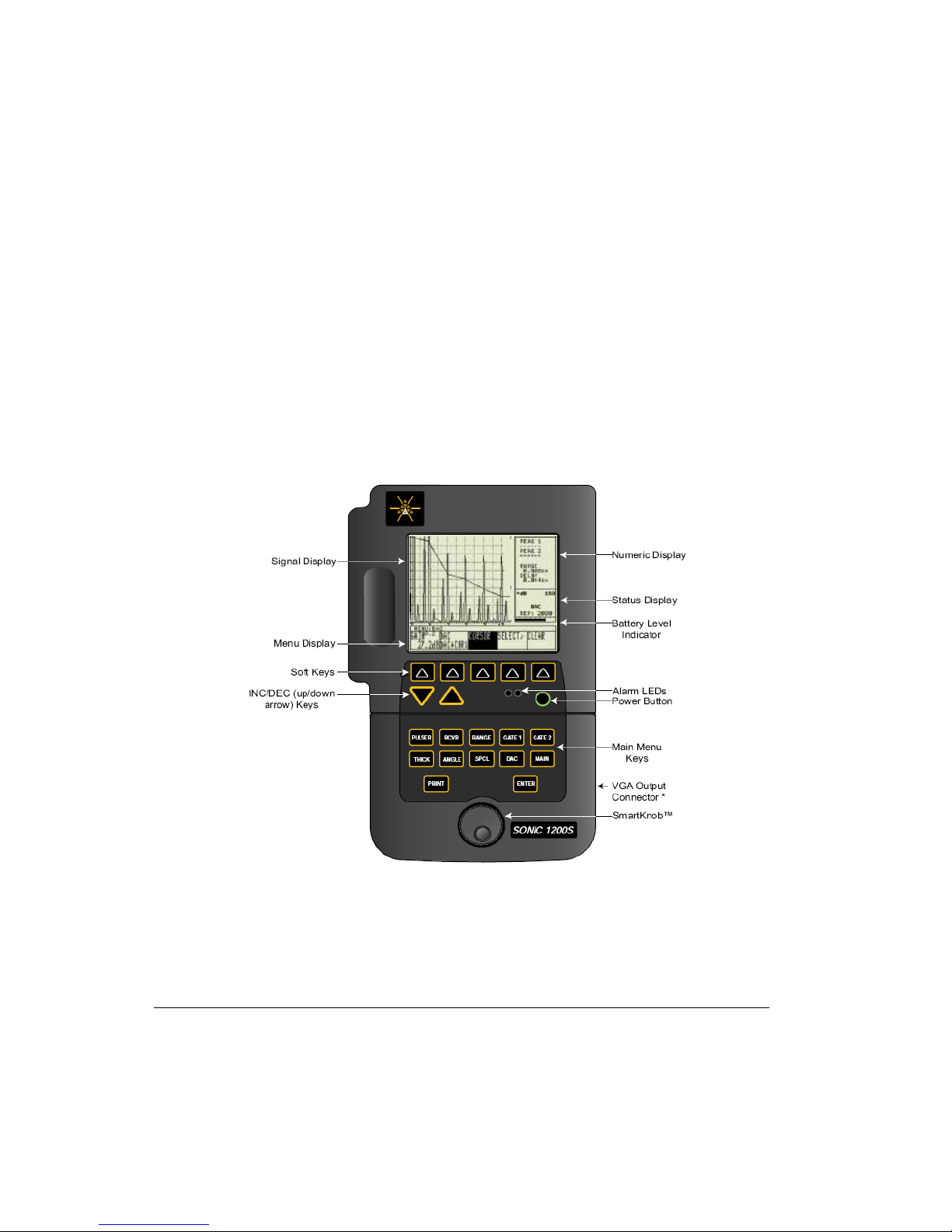
4.1 Instrument Controls
This section covers the operational controls of the Sonic® 1200S/HR.
®
Figure 4-1A: Sonic
36 Chapter 4
1200S Controls
Page 45
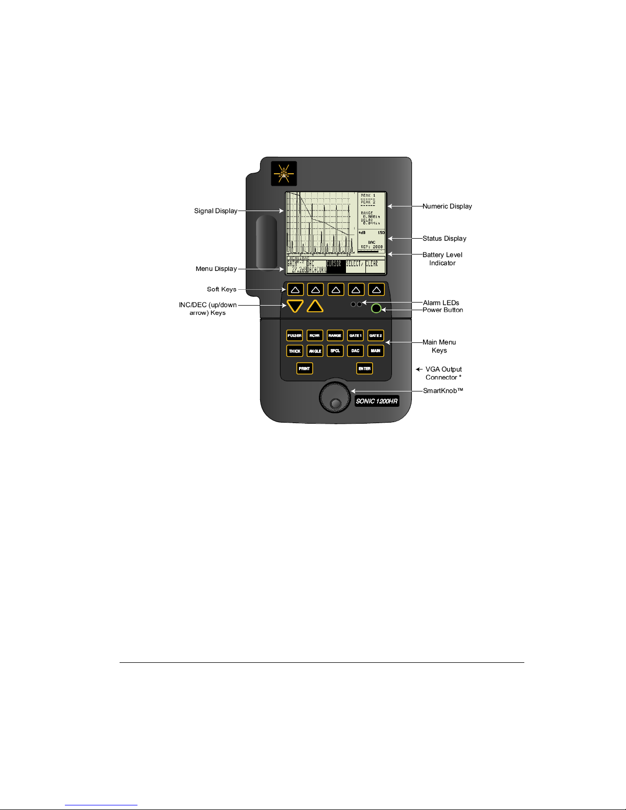
Figure 4-1B: Sonic
®
1200HR Controls
4.2 Power Button
The POWER Button toggles instrument power on and off. Immediately aft er power is turned
ON, an initialization routine is started. The instrument’s microprocessor determines the
instrument configuration, performs power-up diagnostics and calibration, and readies the
instrument for operation. The instrument will normally attempt to restore its last configuration,
but can be made to load factory default settings by pressing and holding the RANGE key while
the instrument powers up.
4.3 Displays
The display contains a symbol indicating remaining battery life. When the unit has
Control Descriptions 37
Page 46
approximately one half hour operating time remaining, a status message in the battery leve l
window indicates a low-battery condition. A low-battery cutoff circuit will automatically
switch the unit off to protect the batteries from excessive discharge.
The instrument may be configured with either an electrolum inescent (EL), monochrome, or
color liquid crystal display (LCD). All displays offer 240 H x 320 V resolution. The display
area is divided into four sections.
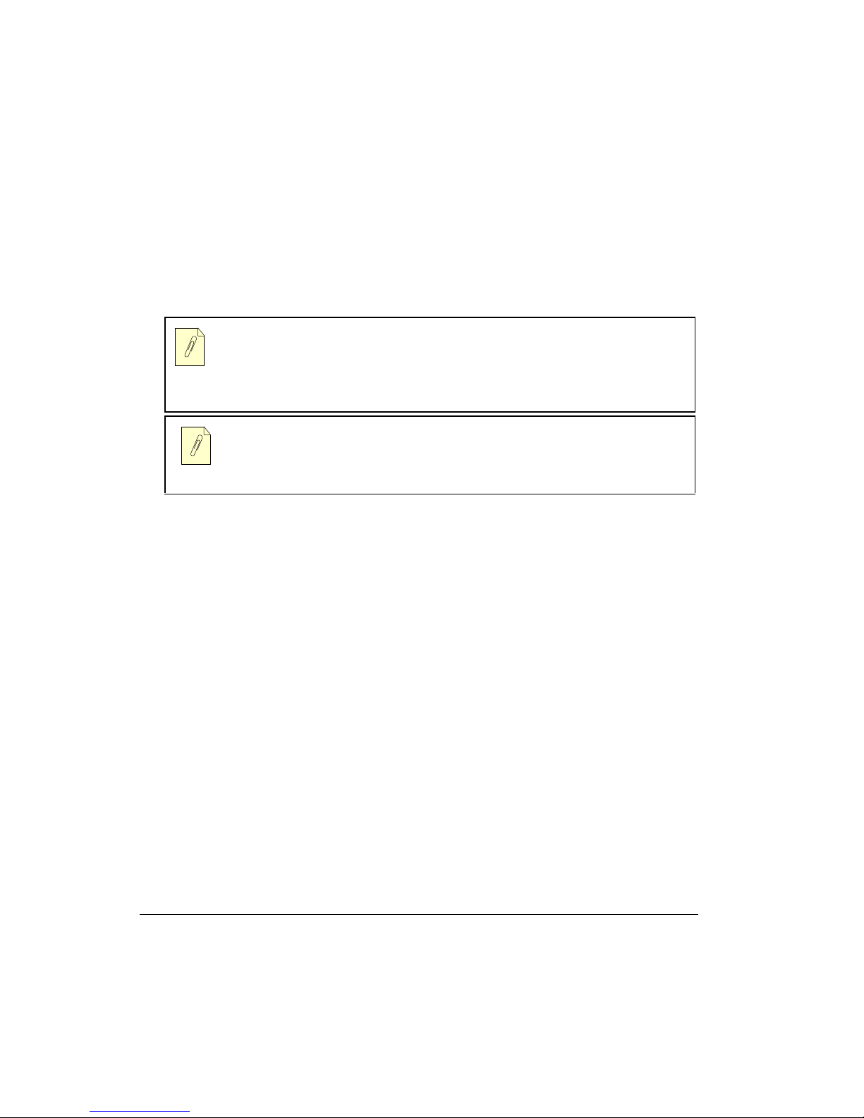
®
The Sonic
1200S/HR has user-interchangeable displays. Failure to turn off power
before exchanging displays will result in loss of stored programs and A-scans, and may
cause other memory corruption errors.
DO NOT attempt to plug a VGA monitor into the 15 pin D connector. This will
result in a damaged instrument and/or VGA monitor.
Signal Display Signal Display is used to display the ultrasonic
signal return from the transducer. It contains a
10 division by 10 division electronic graticule
for signal amplitude and position
measurements. The graticule display is
operator selectable.
Numeric Display Numeric reading of display shows thickness or
peak amplitude readings. In angle beam
inspections, display will show sound path,
distance, and depth readings simultaneously.
Status Display The Status Display shows the operating status
of the instrument and indicates when features
are activated or conditions occur. It is also used
to display prompts and error messages.
Menu Display The Menu Display consists of menu soft key
blocks for displaying instrument operating
parameters. Each menu soft key block contains
a descriptive label of the parameter and its
current setting.
38 Chapter 4
Page 47
Placing the LCD display in direct sunlight will result in tempo rary fade due to the
elevation of internal liquid temperature beyond design specification. Shade or angle the
display away from the sun to assure optimal function.
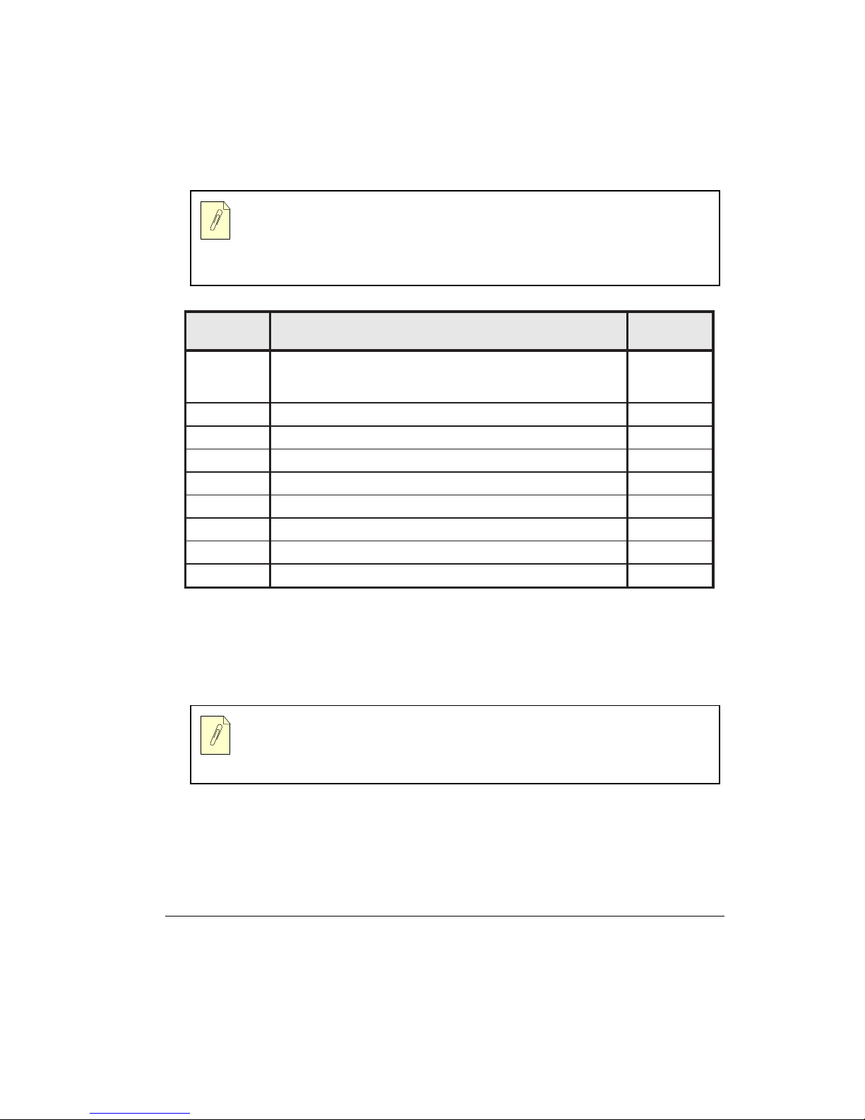
sutatS
srotacidnI
KCOL
nulitnu
MOOZnoigerdetagehtyalpsidotmooznisiyalpsidehTNIAM
WRESLUP
V051.)V003roV051(detcelessiegatlovresluphcih
LAUD.edomtnemelelaudnignitareposireviecer/reslupehTRESLUP
JER.langisdeviecerehtotdeilppagniebsitcej
Bd+.sutatserutaefBd+LLA/LCPS
CAD.langisdeveicerehtotdeilppagniebsiCADsetacidnICAD
LP.desugniebsir
PER.etarnoititepertnemurtsnilautcasyalpsiDEGNAR
.dekcol
erraeniLRVCR
noitidnoC uneM
)KCOLdnaNIAGgnidulcxe(sretemaraptnemurtsnI
lenaptnorfehtmorfdegnahcebtonnacdnadekcolera
ecudsnart™kniLrewoPsetacidnI
LCPS
The EL Hi-Brite Display is capable of switching from a 100% to 30% brightness level. This
feature is accessed by highlighting the Contrast block in the Special Menu, then pressing
ENTER. As with all of our displays, the instrument must be powered off prior to
disconnecting/connecting a new display. Failure to follow this warning may result in
instrument and/or display damage.
The EL Hi-Brite Display may go blank for approximately 1 second after connecting
or disconnecting the Universal Battery Charger. This is normal operation.
4.4 Soft Keys
The soft keys located directly below the display are used to select instrument parameters for
adjustment (using the arrow keys and the SmartKnob
TM
). For some parameters, the soft keys,
Control Descriptions 39
Page 48

when repeatedly pressed, will toggle through specific parameter settings (discrete steps). The
first time a soft key is pressed, the parameter located in the display box directly above the key
will be highlighted using inverse video.
4.5 INC/DEC Arrow Keys
The Increase/Decrease arrow keys may also be used to change parameter settings. The
parameter being adjusted will be displayed in inverse video directly above one of the menu soft
keys. Holding these keys down will cause the rate of adjustment to be increased over time.
4.6 Main Menu Keys
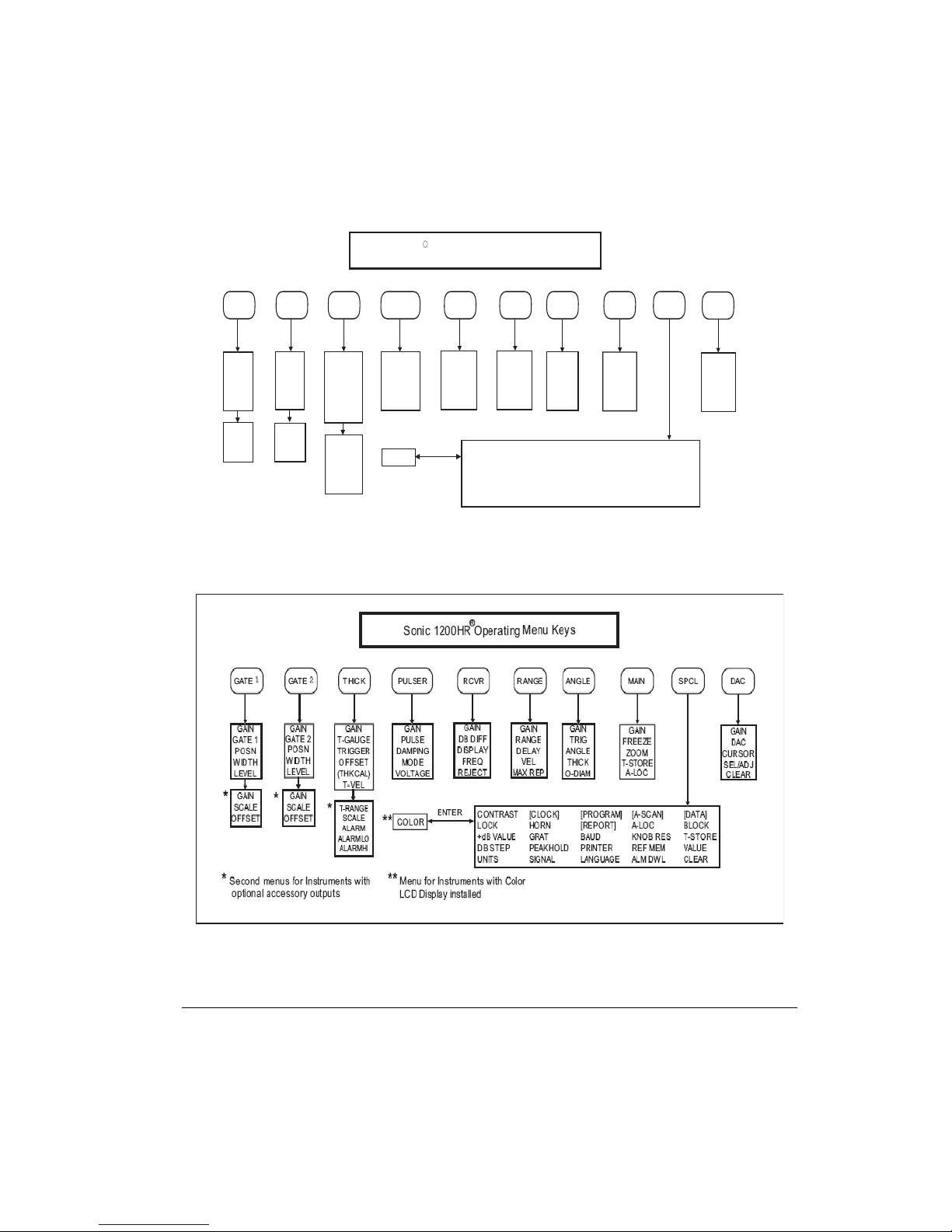
Referring to the front panel view, the PULSER, RCVR, RANGE, GATE 1, GATE 2, THICK,
ANGLE, SPCL, DAC, and MAIN keys are all used to select menus. The parameter to be
adjusted or selected is shown in inverse video above one of the five soft keys. The
microprocessor keeps track of which parameter was last adjusted for each menu. It then returns
the operator to that parameter when the menu key is struck again after moving to a different
menu. The following sections show the different menus and briefly describe the parameters in
each.
There are ten types of menu keys associated with normal inspection procedures that may be
displayed in the soft key Display. Each menu key contains up to five parameters associated
with instrument operation which may be adjusted. The ten primary menus are organized so that
the most important instrument parameters are accessible within two key presses. The SPCL
menu contains a grid of less frequently adjusted parameters.
40 Chapter 4
Page 49
1
2
R
Sonic 1200S Opera ting
Menu Keys
T-GAUGE
TRIGGER
OFFSET
(THKCAL)
T-RANGE
*
ALARMLO
ALARMHI
THICK
T-VEL
SCALE
ALARM
GATE
GATE 2
POSN
WIDTH
LEVEL
*
SCALE
OFFSET
GAIN
GAIN
GAIN
GATE 1
POSN
WIDTH
LEVEL
GAIN
*
SCALE
OFFSET
*
Second menus for Instruments with
optional accessory outputs
GAIN
PULSER RCVR
GAIN
PULSE
DAMPING
MO DE
VOLTAGE
COLOR
**
Menu for Instruments with Color
**
GAIN
DB DIFF
DISPLAY
FREQ
REJECT
ENTER
CONTRAST [CLOCK] [PROGRAM] [A-SCAN] [DATA]
LOCK HORN [REPORT] A-LOC BLOCK
+dB VALUE GRAT BAUD KNOB RES T-STORE
DB STEP PEAKHOLD PRINTER REF MEM VALUE
UNITS SIGNAL LANGUAGE AL M DW L CLE AR
LCD Display installed
RANGE
GAIN
RANGE
DELAY
VEL
MAX R EP
ANGLE
GAIN
TRIG
ANGLE
THICK
O-DIAM
MAINGATE
GAIN
FREEZE
ZOOM
T-STORE
A-LO C
SPCL
DAC
GAIN
DAC
CURSOR
SEL/ADJ
CLEAR
Control Descriptions 41
Page 50
4.7 ENTER Key
The ENTER key may be used to select a sub-menu, toggle a parameter value, execute or
confirm an instrument operation, or respond to an instrument prompt.
4.8 PRINT Key
The PRINT key may be used to produce a hard copy output of the screen information to an
external printer via the RS-232 I/O port. If the printer is not connected or improperly
configured, a SERIAL ERROR! warning will be displayed. Otherwise, a PRINTING message
will be displayed.
4.9 SmartKnob
The primary function of the SmartKnob™ is to change the selected instrument parameters. The
parameter being adjusted will be displayed in inverse text directly above one of the menu soft
keys. The SmartKnob™ is also used to select characters in the edit function for the
programmable report form. In some instances, the SmartKnob™ may be used to respond to
various prompts.
TM
4.10 RCV and XMIT BNCs
The two transducer BNCs (RCV and XMIT) are connected together when the Pulse Echo
mode of operation is selected. A single element transducer may be connected to either BNC
with the same results.
For Dual and Through transmission modes of operation, the transducer excitation pulse is
present at the XMIT BNC only. A fixed 100V load is connected to the RCV BNC in these
modes. The RCV connector monitors the return echoes from the dual element transducer. The
damping control is connected to the XMIT BNC only.
Poor quality or excessively long cable, while not detriment al to the instrument, can
adversely affect signal-to-noise ratio. For best results, use quality cables no longer than
necessary for the operation.
42 Chapter 4
Page 51
4.11 Pulser Menu
PULSER
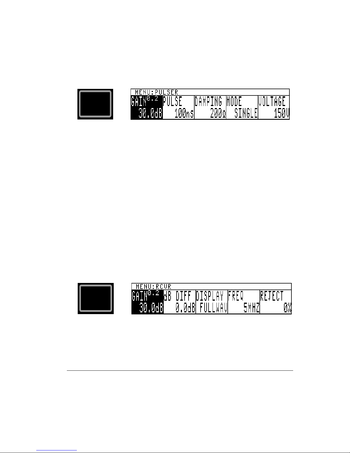
The PULSER menu key invokes the pulser menu shown and is used to adju st the operating
characteristics of the square wave pulser.
GAIN See GAIN parameter description in the Receiver menu section.
PULSE Adjusts the square wave pulse width. The adjustment range is 30ns to 1200ns in 1ns
increments.
DAMPING Selects the damping applied to the transducer crystal. The selections are 25, 50,
and 200 ohms. In PULSE ECHO mode, the damping load is electrically connected to both
transmit XMIT and receive RCV BNCs. In DUAL and THRU XMIT modes, the receive
crystal is connected to a fixed 100 ohm load and the damping load is electrically connected t o
the transmit BNC only.
MODE Selectable between SINGLE, DUAL, and THRU XMIT modes. In SINGLE and
DUAL modes, the sound path distance displayed and the Menu Display range values are
corrected for sound path down and back time.
VOLTAGE Adjusts the square wave pulse voltage. The selections are 150V and 300V. The
selected voltage is shown on the status portion of the display.
4.12 Receiver Menu
RCVR
The RCVR key invokes the receiver menu. This menu is used to adjust the receiver and display
video characteristics.
GAIN Adjusts the receiver gain in 0.2, 1.0, 2.0, 6.0, or 12.0 dB steps (established in the SPCL
menu). The adjustment range is 0 to 110 dB. The maximum gain is limited to 100 dB in
Control Descriptions 43
Page 52
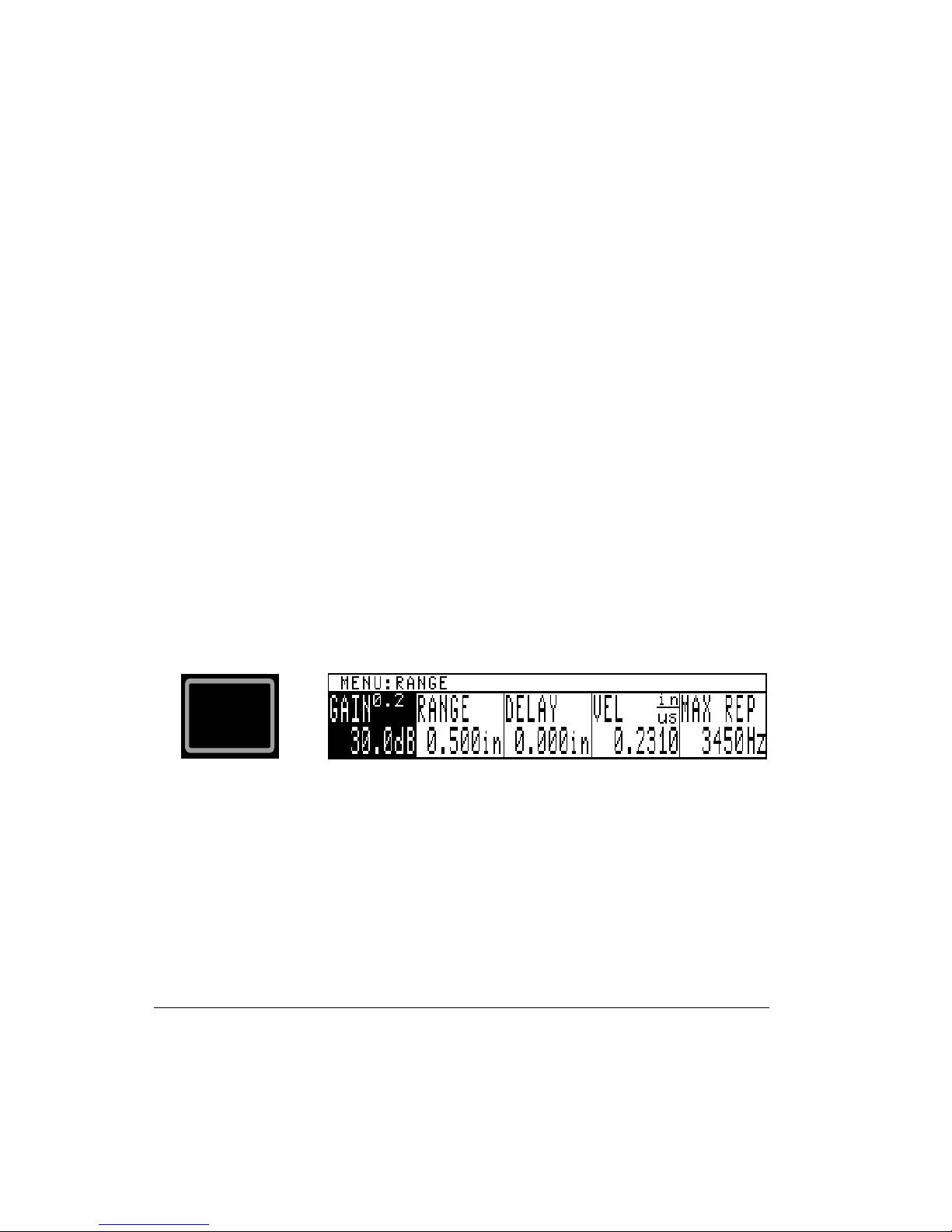
wideband, 10 MHz tuned settings, and all RF displays to limit screen noise. The gain setting is
a relative value and does not reflect actual overall signal gain.
The instrument’s +dB feature is toggled OFF and ON alternately by pressing the gain soft key
when the gain parameter is highlighted. A +dB icon is shown in the status portion of the
display if this feature is active.
DB DIFF Allows the operator to establish a gain reference for signal amplitude comparison.
Pressing this soft key will force the instrument DB DIFF value to +0.0 dB. The DB DIFF value
will track all future changes in the gain value (+/-).
DISPLAY Selects the type of video. Available modes are positive halfwave “HALF+”,
negative halfwave“HALF-”, fullwave “FULLWAV”, “RF”, “RF+”(HR), “RF-”(HR), and
display filter functions (FILTR1, FILTR2, and FILTR3). Filters are only accessible with
software revision R00A or greater.
FREQ Selects the frequency of operation of the receiver filtering circuitry. Selections are
1MHz, 2.25 MHz, 5 MHz, 10 MHz, 15 MHz (HR), WIDEBAND (0.3 - 15 MHz), and HIP ASS
(3 - 15 MHz). When the frequency control is changed, the square wave pulse width is
automatically set to one-half the wavelength of the selected setting.
REJECT Adjusts the linear reject level. This value is adjustable from 0 to 80% of full screen
height in 1% increments. When reject is on, a status indicator is displayed.
4.13 Range Menu
RANGE
The RANGE key calls up the range menu shown and is used to adjust the time base
parameters.
GAIN See GAIN parameter description in the Receiver menu section.
RANGE Adjusts the time base range from 0.048 to 296 inches in steel. Adjustment step size
varies from 0.001 to 1 unit. The range is corrected for the down and back time of the signal
when operating in PULSE ECHO mode. Refer to the VEL description for further Range limits.
44 Chapter 4
Page 53
DELAY Adjusts the ti me base delay from -1.16 to 185 inches in steel. Adjustment step size
varies from 0.001 to 1 unit. Refer to the VEL description for further Delay lim its.
VEL Selects the material sound propagation velocity. The adjustment range is 0.0250 in/µs to
0.6000 in/µs. The allowable minimum and maximum values for range and delay are based on
the velocity setting. If the instrument limits the adjustment for range, delay, gate position, or
gate width, it may be due to the current velocity setting.
MAX REP Adjusts the frequency of the square wave pulse applied to the transducer crystal.
The maximum rate is limited by the Range, Pulse Voltage, and Pulse Width settings.
Decreasing MAX REP may reduce the noise on the display.
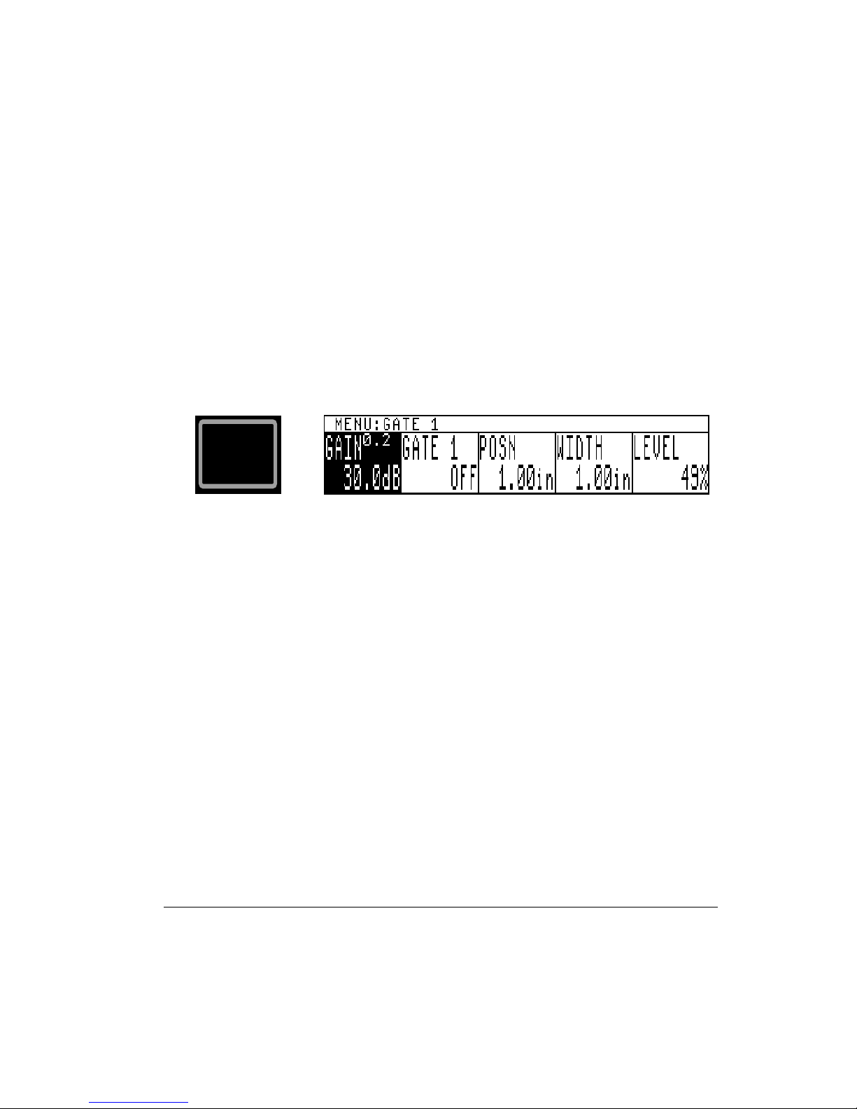
4.14 Gate 1 Menu
GATE 1
The GATE 1 key calls up the gate 1 menu shown an d is used to adjust the gate 1 parameters.
This menu sets up parameters such as polarity, position, width, and level for flaw gate 1. Gate
1 may also be used for thickness measurement by enabling the T-GAUGE control.
GAIN See GAIN parameter description in the Receiver menu section
GATE 1 Selections are “+”, “-”, and “OFF”; “+” signals a gate alarm when the signal
amplitude is above the threshold level, and “-” signals an alarm when the flaw amplitude is
below the threshold level. “OFF” turns off the flaw gate. If a gate is in the alarm state when the
thickness gauge is OFF, the ampl itude is displayed under the associated gate bar in inverse
video.
POSN Adjusts the gate 1 start position from -1.160 to 185.0 inches in steel. The position is
displayed as the distance from IP in the selected units. Adjustment step size varies from 0.001
to 1 unit. Refer to the VEL description for further Gate Position limits.
WIDTH Adjusts the width of gate 1 from 0.001 to 296.0 inches in steel. Ad justment st ep size
is 0.001 to 1 unit. Refer to the VEL description for further Gate Width limits.
LEVEL Sets the gate 1 threshold value in terms of % of full screen height (FSH) for the alarm.
Adjustable from 5% to 100% of FSH in 1% increments.
Control Descriptions 45
Page 54
T o access the Gate 1 second menu, press the GATE 1 key twice. This second menu sets up gate
1 parameters, such as scale and offset, for analog output of echo peak amplitude. When Gate 1
is turned off, the output 1 is set to 0mV. Thickness gauge operation disables Gate 1 outputs.
SCALE Any value from 1000 mV to 4000 mV in 250 mV increments. Default is 4000 mV.
OFFSET Adjustable between -4000 mV and 4000 mV in 10 mV increments. Default is 0 mV.
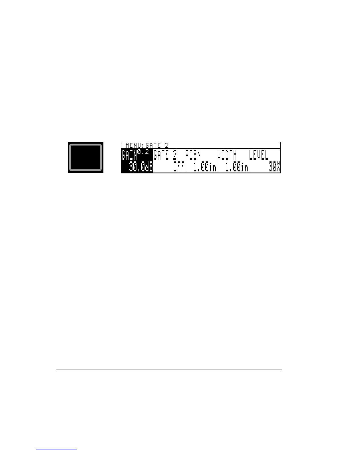
4.15 Gate 2 Menu
GATE 2
The GATE 2 key calls up the gate 2 menu shown an d is used to adjust the gate 2 parameters.
This menu sets up parameters such as polarity +/-, position, width, and level for flaw gate 2.
Gate 2 may also be used by the thickness gauge for echo-echo thickness measurement.
GAIN See GAIN parameter description in the Receiver menu section
GATE2 Selections are “+”, “-”, and OFF; “+” selects the gate alarm when the signal amplitude
is above the threshold, and “-” selects that gate alarm when the flaw amplitude is below the
threshold level. “OFF” turns off the flaw gate. If a gate is in the alarm state when the thickness
gauge is OFF, the amplitude is displayed under the associated gate bar in inverse video.
POSN Adjusts the gate 2 start position from -1.16 to 185.0 inches in steel. The position is
displayed as the distance from IP in the selected units. Adjustment step size varies from 0.001
to 1 unit. Refer to the VEL description for further Gate Position limits.
WIDTH Adjusts the width of gate 2 from 0.001 to 296.0 inches in steel. Ad justment st ep size
is 0.001 to 1 unit. Refer to the VEL description for further Gate Width limits.
LEVEL Sets the gate 2 threshold value in terms of % of full screen height (FSH) for the alarm.
Adjustable from 5% to 100% of FSH in 1% increments.
To access the Gate 2 second menu, press GATE 2 key twice. This second menu sets up gate 2
parameters, such as scale and offset, for analog output of echo peak amplitude. When Gate 2 is
turned off, the output 2 is set to 0mV.
SCALE Any value from 1200mV to 4000mV in 250mV increments. Default is 4000mV.
OFFSET Adjustable between -4000mV and 4000mV in 10mV increments. Default is 0mV.
46 Chapter 4
Page 55
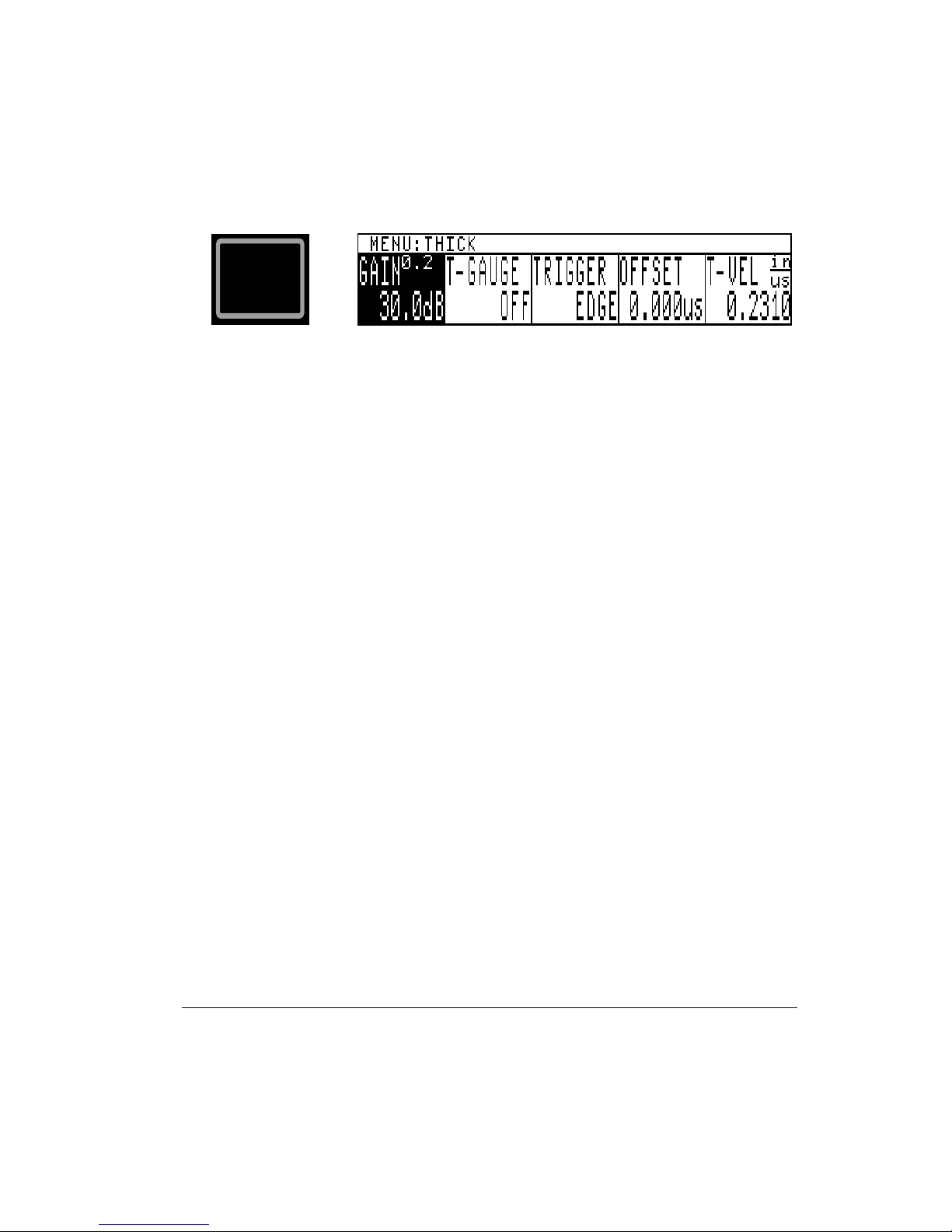
4.16 Thickness Menu
THICK
The THICK key calls up the thickness menu shown and is used to ad just the thickness gauge
parameters. The thickness gauge controls are used to enable, configure, and calibrate the
thickness gauge. The thickness gauge uses gate 1 for IP - 1
ECHO - ECHO.
GAIN See GAIN parameter description in the Receiver menu section.
T-GAUGE Enables or disables the thickness gauge feature and selects the measurement mode.
The thickness gauge may be set to operate in IP - 1
st
to-Echo mode. In Auto IP-1
or Auto Echo-to-Echo mode, Auto-Cal is based on acquiring
st
, Echo-to-Echo, Auto IP-1st, or Auto Echo-
readings of two known thickness references. Notice that in the Auto IP - 1
Echo mode, the OFFSET soft key is replaced by the THK CAL soft key function.
ST
and both gates (1 and 2) for
st
, or Auto Echo-to-
Thickness gating is performed using the instrument’s flaw gate(s). IP - 1
st
thickness
measurements require gate 1, while Echo-Echo thickness measurements require both gates 1
and 2.
Turning the thickness gauge ON forces the appropriate gate or gates ON. Conversely, turning
the thickness gauge OFF forces the appropriate gate or gates OFF. When the thickness gauge
alarm is enabled and an alarm condition occurs, readings will be displayed in inverse video.
Gate alarm conditions cause amplitude readings to be displayed in inverse video.
TRIGGER Selects the part of the signal used to trigger for the thickness measurement.
Selections include edge (leading) or peak.
OFFSET Selects and displays the thickness gauge zero offset. The offset adjustment range is
used to establish the starting point for IP - 1
ST
measurements. Offset is adjustable from -5µs to
100µs.
THK CAL Selects the thickness reference value for CAL PT 1 and CAL PT 2. Press ENTER
key at each CAL PT to advance and calibrate.
T-VEL Selects and displays the thickness gauge material sound propagation velocity. The
adjustment range is 0.0250 in/µs to 0.6000 in/µs.
Control Descriptions 47
Page 56
The allowable minimum and maximum values for part thickness and outer diam eter are based
on the T-velocity setting. If the instru ment limits the adjustment for part thickness and outer
diameter, it may be due to the current T-velocity setting.
T o access the Thickness second menu, press the THICK key twice. This second menu provides
additional thickness gauge parameters.
T-RANGE Selectable 1in./25mm, 5in./125mm, 25in./600mm, 100in./2500mm, and
300in./7500mm. Default is 1in/25mm.
SCALE Output voltage scaleable between 1000mV and 4000mV in 250mV increments.
Default is 4000mV. Over range voltage is 4000mV.
ALARM When the thickness gauge is turned off, the thickness alarm is set to OFF. Default is
OFF.
ALARM LO Default is 0.0 inch. The low alarm cannot be set for a larger value than the high
alarm.
ALARM HI Default is 1 inch. The high alarm cannot be set for a smaller value than the low
alarm.
When the thickness gauge is OFF, the thickness alarm output is set to 0mV or to Gate 1 output
(if the gate 1 is ON).
When the thickness gauge is ON and no signal intersects the gate(s), the alarm output is
4000mV.
4.17 Angle Menu
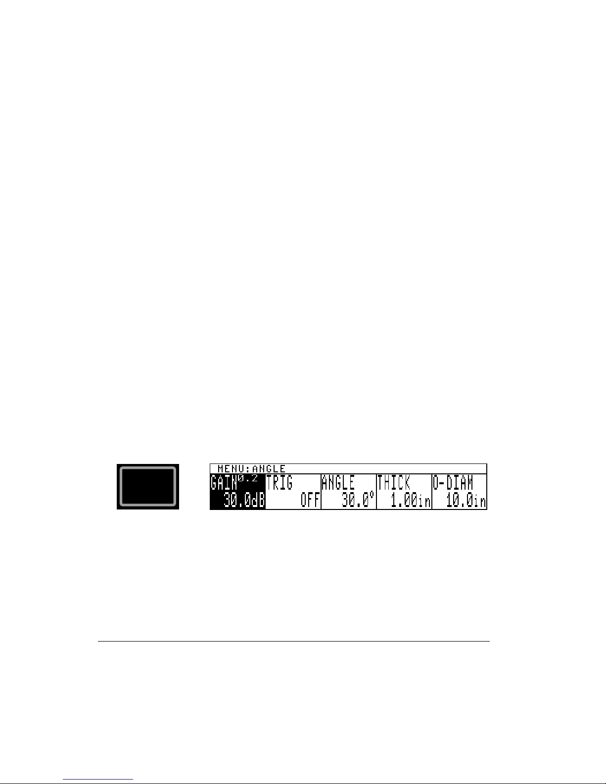
ANGLE
The ANGLE key activates the angle beam measurement menu. This function allows weld and
other shear wave inspection trigonometric calculations to be displayed.
GAIN See GAIN parameter description in the Receiver menu section.
TRIG This control enables and disables the angle beam calculation feature.
48 Chapter 4
Page 57
ANGLE This control enables/disables angle beam calculations and specifies the refraction of
the sound beam into the test part (wedge angle). This control may be adjusted from 0° (OFF) to
90° in 0.1° increments. When an angle is specified, the sound path, depth, and distance
measurements are displayed simultaneously.
THICK The actual thickness of the part under inspection can be specified from 0.001 to 185.0
inches. This entry allows the microprocessor to determine which “leg” the sound beam is in
when an echo is detected, and hence correct the sound path, distance, and depth values for the
leg. This provides the operator with electronic weld soundpath calculation ability. Refer to the
T-VEL description for further THICK limits.
O-DIAM Outer diameter of the curved surface for correction of depth and distance
measurements. The outer diameter may be set to a value in the range of 0.001 inches to 185.0
inches, or it may be turned OFF for flat objects. Refer to the T-VEL description for further ODIAM limits.
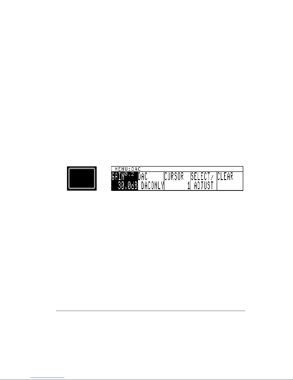
4.18 DAC Menu
DAC
The DAC key activates the DAC menu. This menu offers controls that allow the operator to
construct and modify a DAC/Curve.
GAIN See GAIN parameter description in the Receiver menu section
DAC The DAC control selects the operating mode of the DAC circuitry. The options are
OFF, CURVONLY, 3 CURVES, 4 CURVES, JIS, DACONLY, and DAC+CURV. 3 CURVES
displays the programmed curve and the curves ±6dB above and below the programmed curve.
4 CURVES displays the programmed curve, the curves 6dB ab ove and below the programmed
curve, and -14dB below the programmed curve. JIS displays the programmed curve, the curves
6dB above and below the programmed curve, and -12dB below the programmed curve.
CURSOR Allows a DAC cursor, a small display circle that tracks signal peaks, to be moved
back and forth across the screen to select points where DAC compensation will be calculated,
and the amplitude of the selected points will be adjusted. Repeated presses of this soft key
control will jump the cursor from one previously defined point to the next.
Control Descriptions 49
Page 58
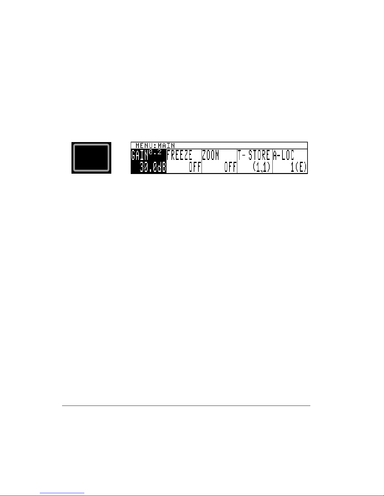
SELECT/ADJUST This control allows selection of a new DAC point and/or amplitude
adjustment of the selected DAC point. Amplitude adjustment is only available when the DAC
control is set to DACONLY or DAC+CURV.
CLEAR Allows clearing the DAC/DAC Curve.
4.19 MAIN Menu
MAIN
The MAIN key invokes the main menu and its parameters. The main menu contains
parameters that offer one touch storage and feature control.
GAIN See GAIN parameter description in the Receiver menu section.
FREEZE The FREEZE control activates and deactivates the freeze feature. The FREEZE
function will “freeze” the current A-Scan display and allow thickness measurement. Pressing
the PULSER, RCVR, RANGE, or SPCL key turns off the Freeze function.
ZOOM The ZOOM feature allows the operator to expand the contents of the gate 1 region to
full screen width. Toggle ZOOM off and on for the desired display.
T-STORE With this parameter highlighted, repeated presses of the T-STORE soft key store
the displayed thickness reading in the specified location and increment the location numbers.
The arrow key may be used to increase or decrease the storage location. The instrument will
not advance the location number beyond the limit of the blo ck. To use T-STORE, T-gauge
must be on and a data logger block defined.
A-LOC The A-LOC function stores the displayed A-Scan in the specified storage location and
automatically increments the location number. If the selected location is FULL, the location
number will have an “(F)” next to it, the store operation will NOT take place, and an
“INVALID” indicator will be displayed on the status line. The instrument will not adv ance the
location number beyond the A-Scan storage limit of 100.
50 Chapter 4
Page 59
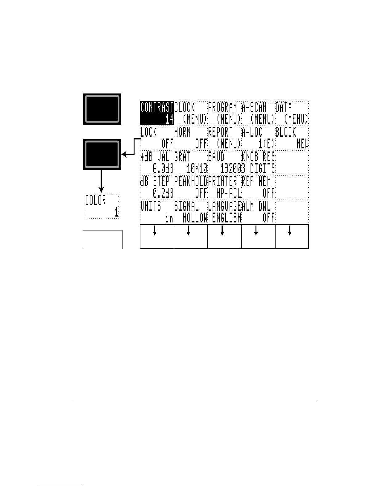
4.20 SPCL Menu
SPCL
ENTER
*
* second menu item
by pressing ENTER
key.
SPCL key provides parameters and features not associated with normal inspection operations.
These include menus for front-panel lockout, date, program, A-Scan storage, and
communications. Select SPCL menu parameters by pressing the appropriate column arrow soft
key until the desired parameter box is highlighted. Use the SmartKnob, arrow keys, or ENTER
key to activate or adjust a parameter. The sub-menus are described in the following sections.
CONTRAST Adjusts the contrast for the Monochrome LCD display. If the ambient
temperature causes the LCD to become invisible, this adjustment can be reached on power up
by simply pressing the SPCL key.
LOCK Enables or disables instrument front panel lock feature. When lock feature is enabled,
all controls, except gain/lock, are disabled. Pressing ENTER invokes COLOR function if
COLOR display exists.
COLOR Pressing ENTER while LOCK is highlighted brings up the COLOR palette option, if
a color LCD module is detected, COLOR options are 1 to 8. Pressing ENTER again returns to
the LOCK function.
Control Descriptions 51
Page 60

+dB VALUE Establishes the amount of gain applied by the +dB feature. The selections
include +6 dB, +12 dB, +18 dB, and +24 dB.
TM
dB STEP Establishes step size used by SmartKnob
and arrow keys to adjust gain value.
Selections are 0.2, 1.0, 2.0, 6.0, and 12.0 dB.
UNITS Selects various operating units. Selections: inches (in), millimeters (mm) or
microseconds (µs).
CLOCK System clock menu for setting the instrument time and date.
HORN Enables or disables the audible alarm horn.
GRATICULE Sets graticule to OFF, 5x5 grat icule, 10x10 graticule, or JIS 10x10 graticule.
PEAKHOLD Performs a peak detect and hold function of the digitized wave forms. The peak
amplitude of the digitized signal is displayed, held, and updated whenever a new higher peak
amplitude is detected. The peak hold may be reset by pressing the ENTER key when this
function is active.
SIGNAL Allows selection between a hollow or filled A-Scan display.
PROGRAM Program storage and retrieval sub-menu.
REPORT Report form editor sub-menu.
BAUD Used to set the baud rate for the RS-232 serial port selections. If the printer does not
appear to work properly, or the instrument is connected to a host PC and is responding
incorrectly, check to make sure this selection matches your application. For the optional printer
available for use with this instrument, the default setting is 9600 baud.
PRINTER Used to select one of the printers supported by the Sonic
®
1200S/HR. The printer
selection includes Epson, HP-PCL, Canon, and Pentax II. Each of these selections may be used
with a wide range of printers. To use a specific printer, your selection must su pport or emulate
one of the printer selection modes and be configured accordingly. Some printers support
several printer modes, so experimentation may be required to determine which mode provides
the best printout.
LANGUAGE Sets language used for text. Selections include English, Spanish, French,
German, Italian, Romanian.
A-SCAN A-Scan storage and retrieval sub-menu.
52 Chapter 4
Page 61

A-LOC Selects the next storage location for an A-Scan.
KNOB RES Knob Resolution allows selecting between 3-digit display or 4-digit display.
REF MEM The Reference Memory function allows the operator to save a waveform through
normal A-Scan save in the Main menu, recall it as “REF MEM”, then compare the “REF
MEM” with a live echo pattern. When recalled, the saved “REF MEM” waveform is displayed
as a dotted line.
DATA Thickness data logger sub-menu.
BLOCK Selects the measurement block number.
T-STORE Selects the next storage location for a thickness reading.
VALUE Displays a stored value or empty status for the current block/location selection.
CLEAR Clears the contents of the selected LOCATION. Note that this operation is
irreversible.
ALM DWL Alarm dwell is accessed through the Special Menu. Selections for alarm dwell are
OFF, 0.2, 0.4, ..., 10.0 seconds and LATCH. If LATCH is chosen, the alarm is activated
whenever an alarm condition is met and keeps alarming. To deactivate the latched alarm, press
the SPCL key when the alarm condition no longer exists.
Control Descriptions 53
Page 62
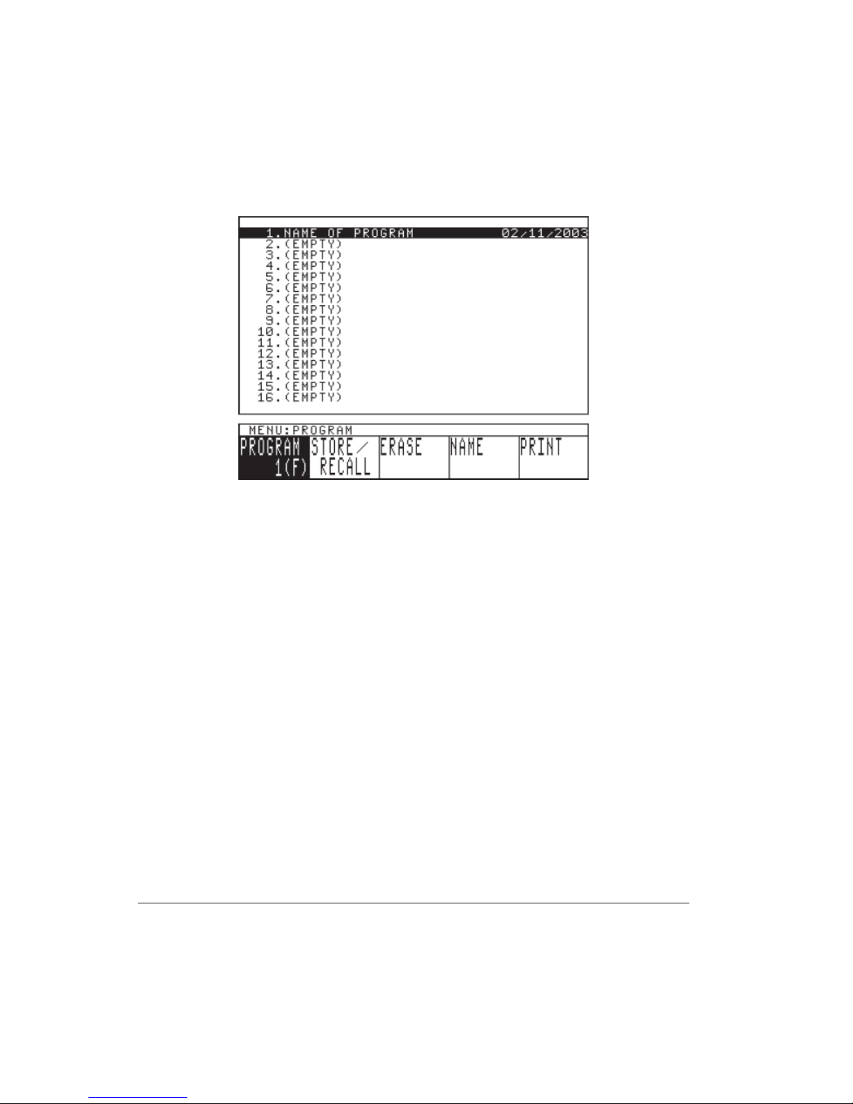
4.21 Program Sub-Menu
The Sonic® 1200S/HR is capable of storing and retrieving 100 complete instrument program s.
These setups are recorded with date and time, and may be named using up to 29 alphanu meric
characters. Functions pertaining to program storage are store, recall, erase, name, and print.
PROGRAM This line displays the program storage location which is t o be stored, recalled,
erased, named, or printed. Turning the SmartKnob™ will cycle through the 100 program
storage locations and highlight the current selection. The locations are displayed in pages of
16. Along with its storage location, the program’s empty status or name and time stamp will be
displayed.
STORE/RECALL Instrument settings are stored to or recalled from the selected program
location. If the selected location is full, this control allows the operator to recall the stored
program. If the location is empty, t he operator is permitted to store the program. Whenever a
program setting is recalled, the currently active instrument settings are overwritten and cannot
be recovered unless these settings were previously stored in another program location.
ERASE The erase function allows the operator to erase the selected program location. Th is is
normally done before saving a new program to that location. If it is desired to erase all program
settings, the program location must be set to the ALL state. Operator confi rmation ENTER is
required to complete the erase operation. Note that this operation is irreversible.
NAME The name function allows the operator to enter a name of up to 29 characters for a
stored program. Names may be used to describe the test settings that are stored, reference a
54 Chapter 4
Page 63
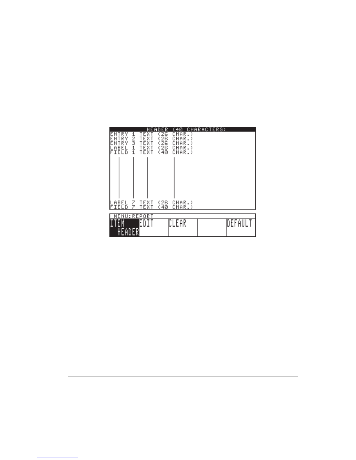
written test procedure, and so on. Only programs that are not empty may be named.
PRINT The program print function uses the optional external serial printer option to make a
hard copy of the currently selected program settings.
4.22 Report Form Sub-Menu
The Sonic® 1200S/HR offers an internal text editor to customize the report form. The report
consists of a header, seven fields and associated labels, and three report entries. Each of these
items is programmable by the user.
ITEM This line displays the report item currently selected. The selected item will also be
highlighted. Turning the SmartKnob™ will cycle through the items (HEADER, ENTRY1-3,
LABEL1-7, and FIELD1-7).
EDIT Invokes the text editor to customize the selected report item.
CLEAR Clears the currently selected report form item.
DEFAULT Replaces all report items with their factory default strings.
Control Descriptions 55
Page 64
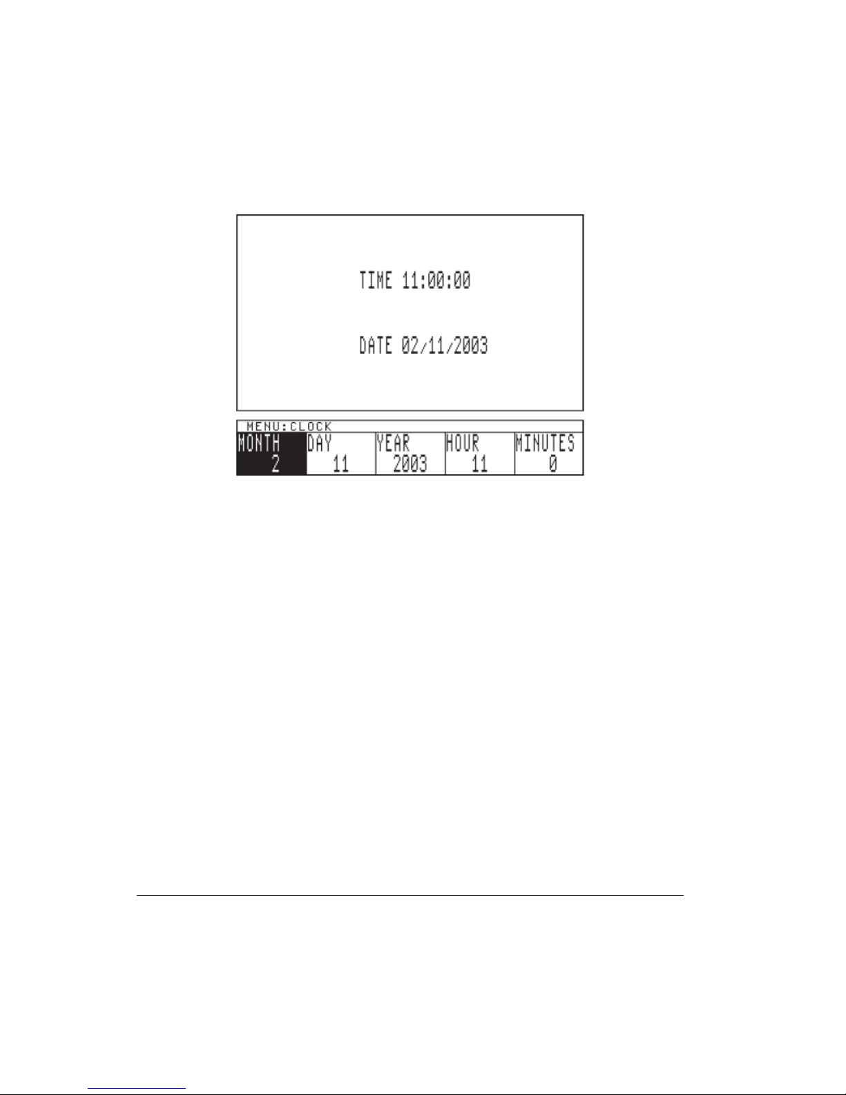
4.23 Clock Sub-Menu
The Clock sub-menu is used to observe and modify the system clock parameters. The system
date is expressed in DD MM YYYY format, while the system time is expressed in HH:MM
format.
MONTH Sets the system clock month (i.e., 1 = January, 2 = February, etc.).
DAY Sets the system clock to the day of the month (days 1 through 31).
YEAR Sets the last 4 digits of the system clock year (1996 through 2095).
HOUR Sets the system clock to the hour (0 through 23).
MINUTES Sets the system clock to minutes (0 through 59).
56 Chapter 4
Page 65
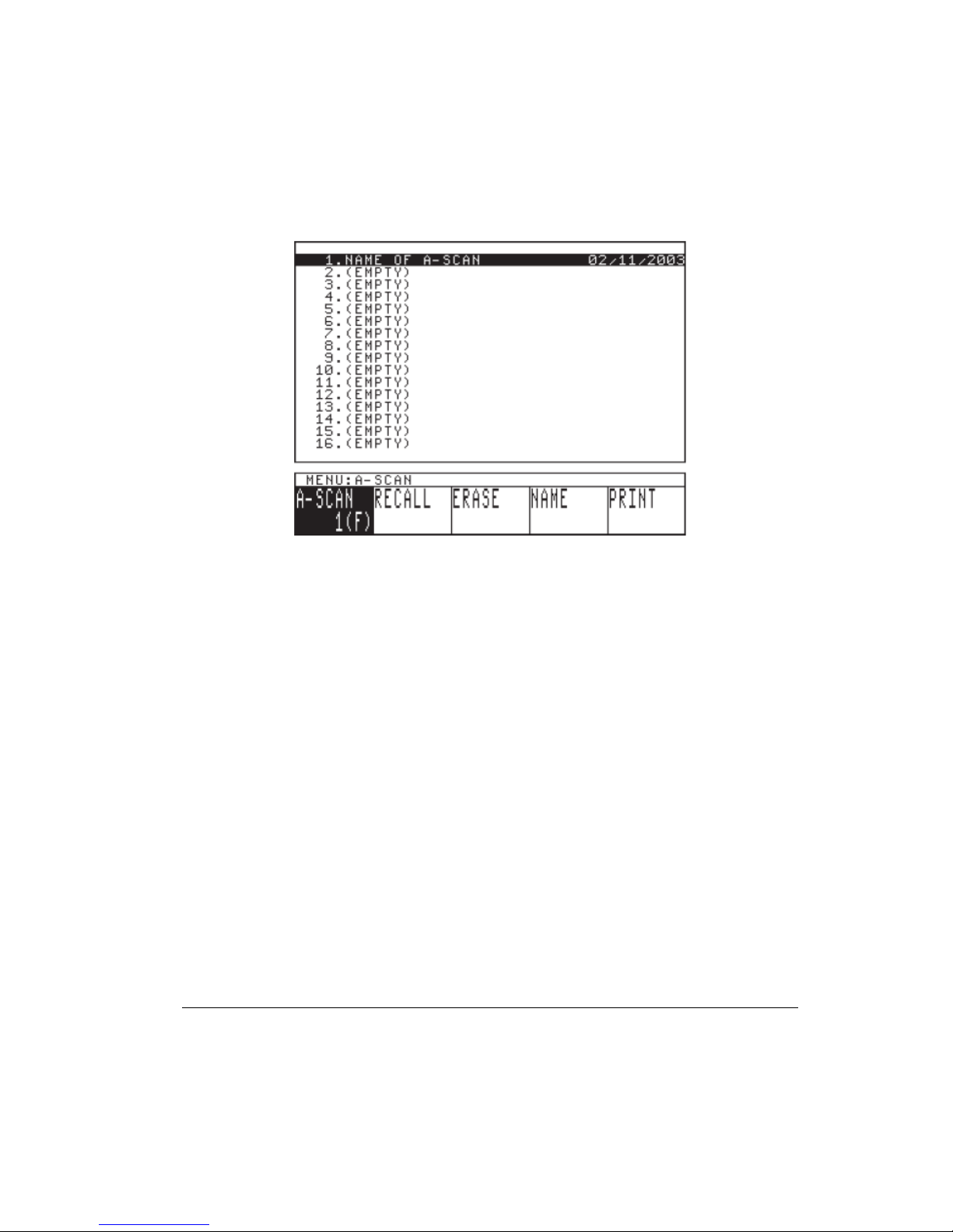
4.24 A-Scan Sub-Menu
The Sonic® 1200S/HR is capable of storing and retrieving 100 complete A-Scans. These AScans are recorded with date and time, and may be named using up to 29 alphanumeric
characters. A-Scans are stored in the MAIN menu using the A-LOC feature. Functions
pertaining to stored A-Scans are recall, erase, name, and print.
A-SCAN This parameter displays the A-Scan memory location which is to be stored, recalled,
erased, named, or printed. Turning the SmartKnob™ will cycle through the 100 A-scan storage
locations and highlight the current selection. Along with the displayed A-Scan storage location
will be its empty status or name and time stamp.
RECALL A-Scan images may be recalled from the selected A-Scan location to the instrument
screen for review. Only full A-Scan locations may be recalled. To resume normal instrument
operation, press any key.
ERASE The erase A-Scan function allows the operator to erase the selected A-Scan location.
This is normally done before saving a new A-Scan to that location. To erase all A-Scans, the
A-Scan location must be set to the ALL state. Operator confirmation ENTER is required to
complete the erase operation. Note that this operation is irreversible.
NAME The name function allows the operator to enter a name of up to 29 characters for a
stored A-Scan. Names may be used to describe the test settings that are stored, reference a
written test procedure, and so on. Only A-Scans that are full may be named.
Control Descriptions 57
Page 66
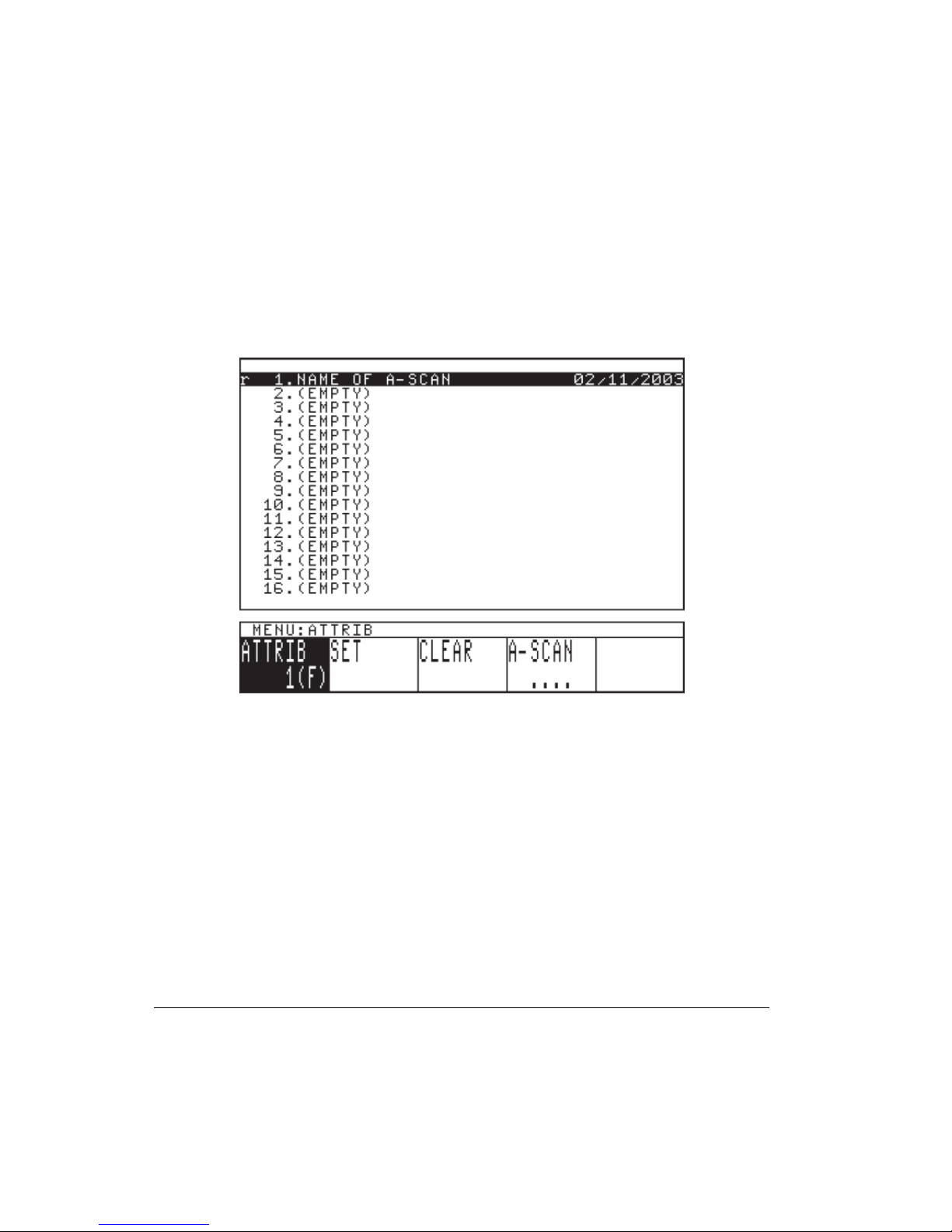
PRINT The A-Scan print function uses the optional external serial printer option to make a
hard copy of the stored A-Scan, program settings, and a custom report form.
ATTRIB Attribute appears only when A scan location is ALL. Press ENTER to access the A
scan Attribute sub menu. when this soft key is highlighted.
4.25 A-Scan Attribute Sub Menu
The first character in the table above indicates the attribute of the A-Scan location.
• [r]read-only
• [e]extension of previous location
Setting the attribute of A-Scan locations protects these locations from accidentally being
erased. SET sets the attribute of the stored A-Scan, and CLEAR clears the attribute.
ATTRIB This parameter display s the A-Scan memory location on which the attribute is to be
changed. Rotating the SmartKnob™ will cycle through the 100 A-Scan locations.
SET The SET function is used to set the attribute of the highlig hted A-Scan location. The A-
Scan can NOT be erased if the attribute is set.
58 Chapter 4
Page 67
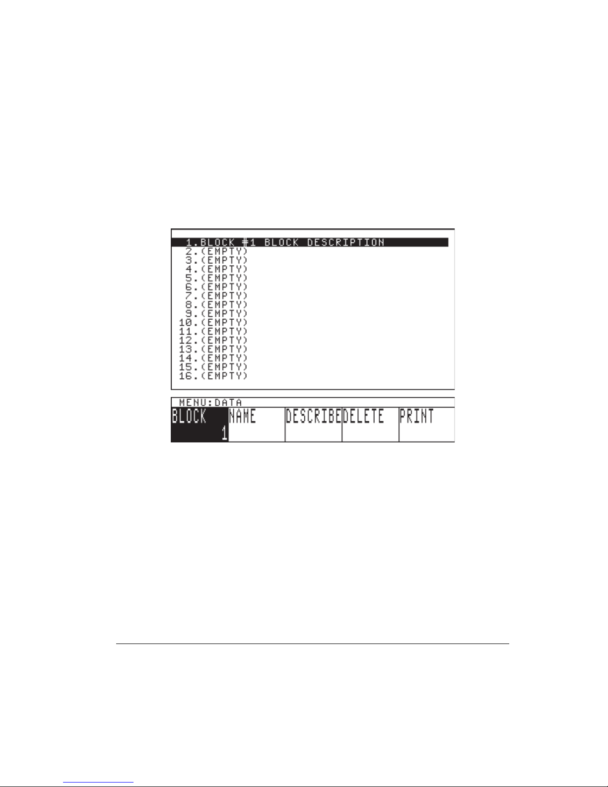
CLEAR The CLEAR function is for clearing the attribute of the highlighted A-Scan location.
The attribute must be cleared before attempting to erase the location in the A-Scan Sub-Menu.
A-SCAN Pressing this softkey or ENTER while it is highlighted returns unit to A-SCAN submenu.
4.26 Data Sub Menu
The data logger menu offers block creation, editing, and review features. Having selected a
block number, the operator performs an operation by pressing ENTER or the appropriat e soft
key.
BLOCK Selects the block number to be REVIEWed, NAMEd, DESCRIBEd, DELETEd, or
PRINTed. All blocks will be listed by name in the top part of the display. Setti ng the BLOCK
number to less than 1 will allow the ALL selection to be used by the DELETE and PRINT
features. Setting the block number to one greater than the last block number will allow the
NEW selection to create a new data block. To create a new data block or review an existing
block, press the ENTER key.
NAME The name function allows the operator to enter a name of up to 8 characters for data
block.
Control Descriptions 59
Page 68
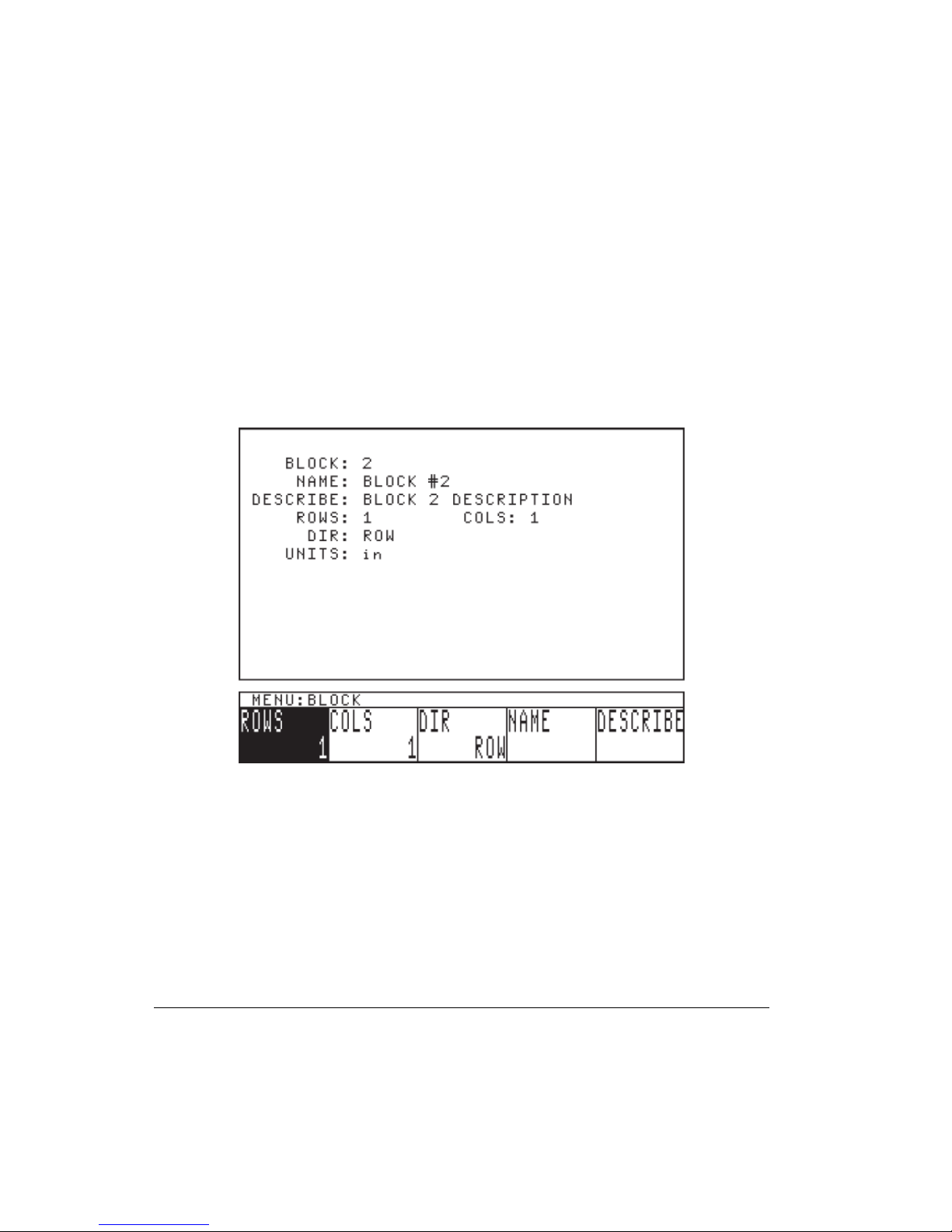
DESCRIBE The describe function allows the operator to enter an alphanumeric block
description of up to 26 characters.
DELETE Allows the operator to delete the selected block number. If it is desired to delete all
data blocks, the block location must be set to the ALL state. Operator confirmation ENTER is
required to complete the delete operation. Note that this operation is irreversible.
PRINT The block print function uses the optional external serial printer option to make a hard
copy report of data contained in the selected block.
4.27 New Block Editor
The new block editor is used to establish the storage requirements for a newly created data
block. The operator must specify the number of rows and columns, as well as the storage
direction. If a sequential configuration is desired, simply set either the rows or co lumns value
to 1. This menu also offers the operator an opportunity to define the blockís name and
description.
ROWS Sets the number of grid rows for this d ata block. The number of rows is adjustable i n
the range of 1 to 5000, but may be limited by the number of columns or available reading
locations.
60 Chapter 4
Page 69
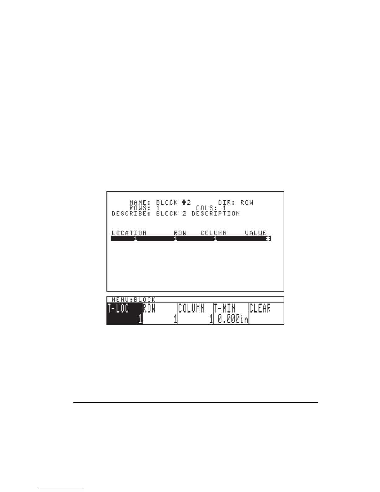
COLUMNS Sets the number of grid columns in this data block. The number of columns is
adjustable in the range of 1 to 5000, but may be limited by the number of rows or available
reading locations.
DIR Sets the load direction for data storage. The selection (ROW or COLUMN) determines
which index will advance after each store operation.
NAME The name function allows the operator to enter a name of up to 8 characters for the
new data block.
DESCRIBE The describe function allows the operator to enter an alphanumeric block
description of up to 26 characters.
4.28 Block Review Sub Menu
The block review sub-menu is used to review the contents of stored data blocks. The screen
contains the block definition items (name, rows, cols, ...) and a page of stored thickness
readings. The readings are listed sequentially (in the order they were stored), but may be
accessed sequentially by row or by column.
LOCATION Selects the block reading location. The location number will change either the
row or column values, or both. Conversely, changes to the row and column values will affect
Control Descriptions 61
Page 70
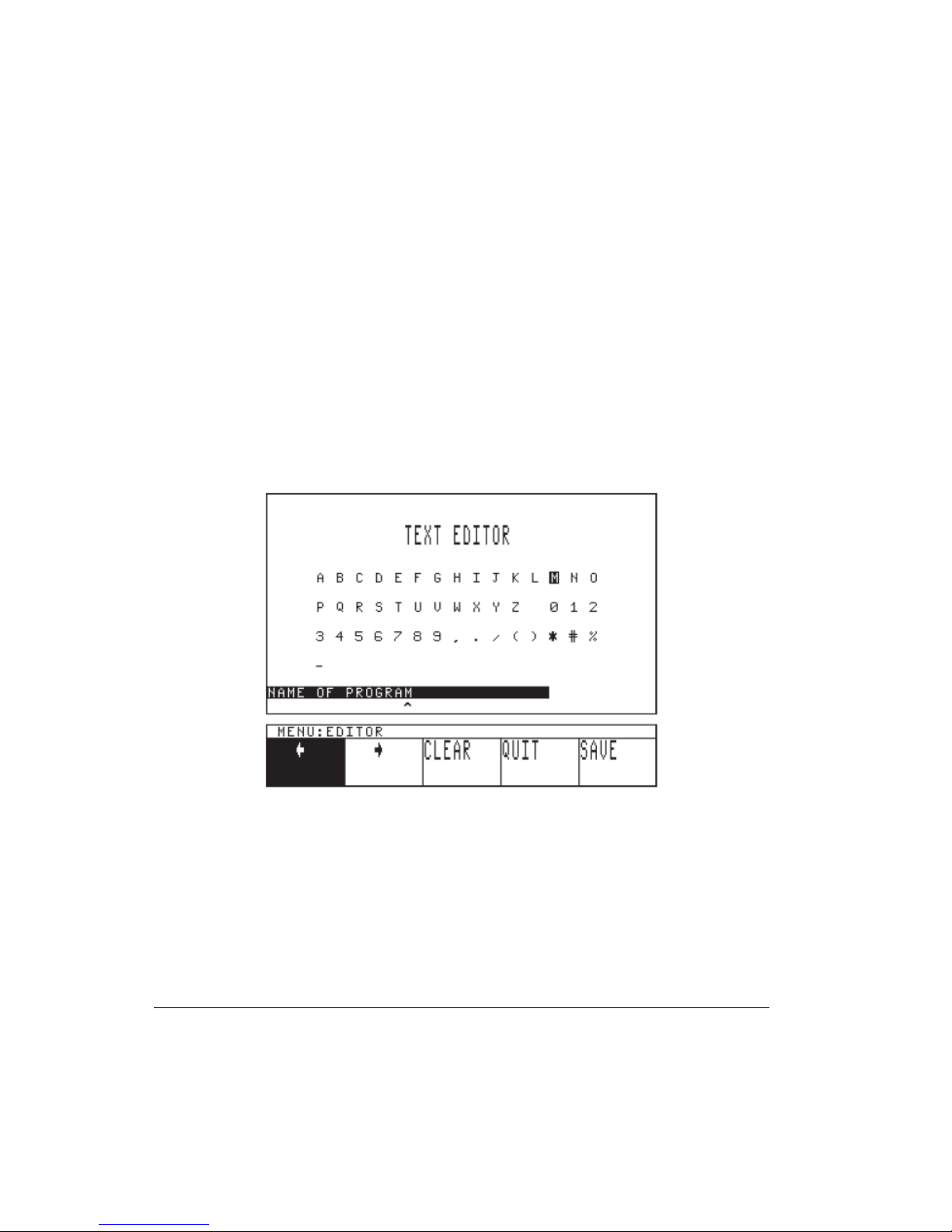
the location number. Setting the LOCATION number to less than 1 will allow the ALL
selection for use by the CLEAR feature.
ROW Changes the row selection, which in turn changes the location value.
COLUMN Changes the column selection, which in turn changes the location value.
T-MIN Establishes the minimum allowable thickness reading permitted by this block. All
readings that are less than this value are marked with an asterisk.
CLEAR Clears the reading(s) from the selected location(s). Operator confirmation ENTER is
required to complete the clear operation. This operation will leave the selected location empty.
Note that this operation is irreversible.
4.29 Text Editor
The text editor presents a screen similar to the figure shown above, displaying a list of
available characters and a highlighted entry line with a pointer used to indicate the current
character location.
The right and left arrow keys are used to move the current character space. Rotating the
SmartKnob moves the highlight from character to character. Pressing ENTER selects the
character and moves the pointer from one location to the right.
62 Chapter 4
Page 71

Right and Left Arrow Keys This line moves edit cursor left and right 1 character position
(respectively). When the cursor exceeds either end of the string, its position wraps around to
the other end.
CLEAR Clears the entire text line and places the edit cursor at the first character.
QUIT Terminates the text editor and aborts any changes made to the text string.
SAVE Saves the text string and exits the text editor.
4.30 Instrument Reset
The instrument operating parameters are reset to the default settings if the RANGE key is
depressed when the instrument is turned on. The instrument will p rompt “Press RANGE key
for default reset” during the initialization routine. Stored programs, thicknesses, and A-Scans
are not affected by the reset operation. The default parameters are listed in the following
charts.
resluP revieceR egnaR
ESLUPsn001NIAG
GNIPMAD002YALPSIDVAWLLUFYALEDni000.0
EDOMqerFelgniSQERFzHM5LEVsµ/ni0132.0
RESLUPv051TCEJER%0STINUni
1etaG 2etaG ssenkcihT
1ETAGffO2ETAGffOEGUAG-TffO
LEVEL%04LEVEL%05REGGIRTegdE
NSOPni005.0NSOPni005.0TESFFOsµ000.0
HTDIWni052.0HTDIWni052
elgnA laicepS
GIRTffOTSARTNOC41ELUCITARG5x5
ELGNA°0.0KCOLffODLOH-KAEPffO
KCIHTni00.1EULAVBd+Bd6+LANGISwolloH
MAID-OffOPETSBdBd2.0E
------STINUNIRETNIRPLCP-PH
------NROHffOEGAUGNALhsilgnE
2.0
Bd03EGNARni00.1
.0LEV-Tsµ/ni0132.0
TARDUAB0069
Control Descriptions 63
Page 72

64 Chapter 4
Page 73

5. Applications
What's in this section?
• 5.1 Pulse-Echo Contact Thickness Testing
• 5.2 Dual Transducer Thickness Testing
• 5.3 Delay Line Thickness Testing
• 5.4 Shear Wave (Angle Beam) Testing
• 5.5 Distance Amplitude Correction (DAC) Testing
5.1 Pulse-Echo Contact Thickness Testing
One of the major methods of ultrasonic thickness testing is the pulse-echo contact method. It
provides excellent accuracy and is best suited for smooth surfaces. The test range is usually
0.10 inch to 20.0 inches. A wideband transducer is normally used. The thickness gauge offsets
and sound velocity must be recalibrated each time the instrument is powered up.
The following accessories are required for this setup procedure:
STEP BLOCK — Sonic
0.200, 0.300, 0.400, and 0.500 inch steps.
TRANSDUCER — The transducer used will depend on the material and
thickness being tested. For steel or aluminum up to 5 inches thick, a Spectrum
E8L (5 MHz) transducer is a good selection. For rough, corroded, or highly
attenuative materials, a 2.25 MHz transducer (Spectrum™ E4L) may be required.
Larger and lower frequency transducers may give better results on rough
materials (that is, cast iron).
TRANSDUCER CABLE — Use a Sonic
BNC/BNC (#9102892) to connect the specific transducer.
®
#1920105.00 Steel Step Block or equivalent 0.100,
®
BNC/Microdot (#9102894) or
Applications 65
Page 74
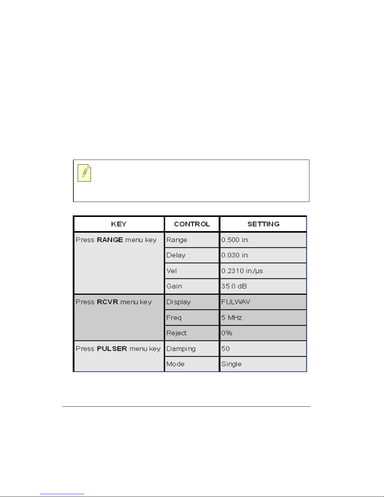
COUPLANT — Use a couplant that “fills in” the surface. On smooth surfaces,
thinner couplants can be used such as water, light oil, or mineral oil. On rough
®
surfaces, Sonic
X30S couplant (#3317450) is more appropriate.
5.1.1 Instrument Calibration - 0.5” Thickness Range, Steel
1. Connect the transducer cable to the Spectrum™ E8L transducer, and then to either BNC
connector.
2. Turn on instrument power and adjust the operating controls as follows:
To select and change the follow ing parameters, press the menu soft key below the
selected menu box, then rotate the SmartKnob™ or press the INC/DEC arrow keys to
change the value.
3. Place X30S couplant on the step block and position the transducer on the thinnest (0.100)
step.
66 Chapter 5
Page 75
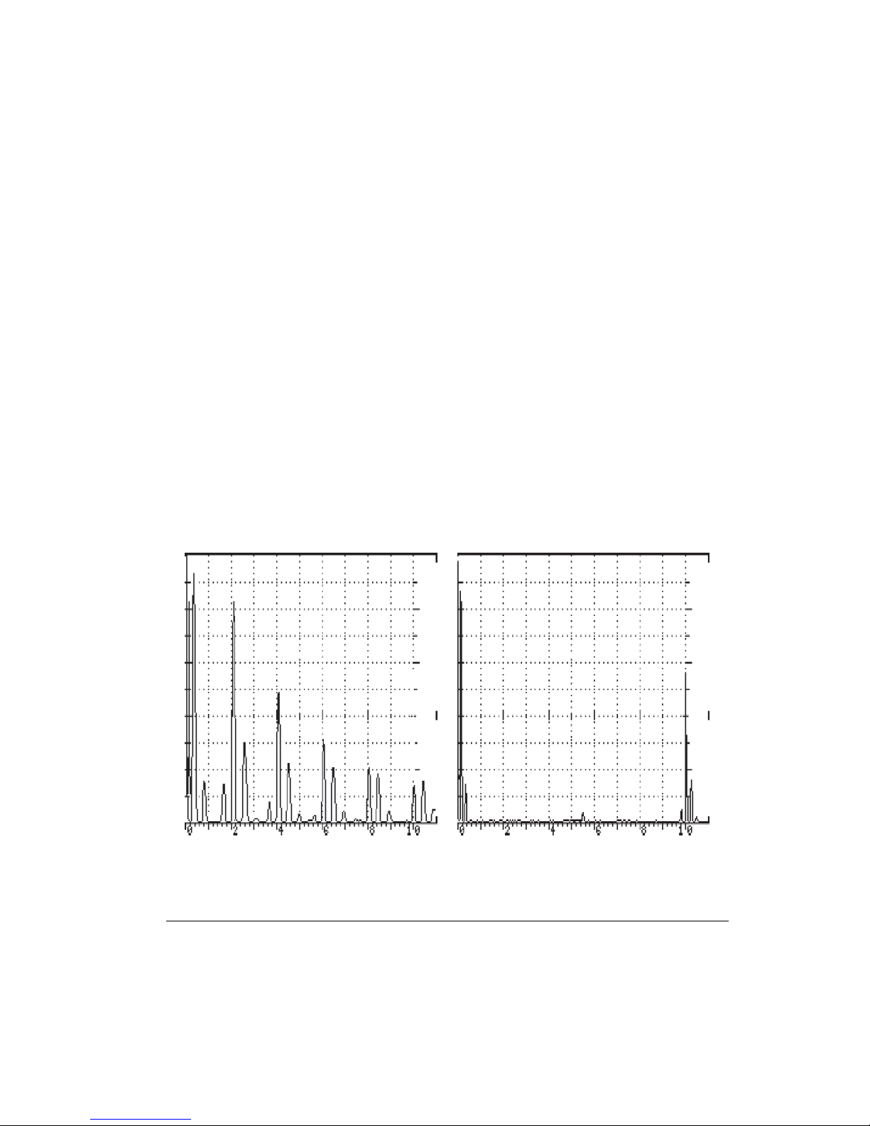
4. Press the RCVR menu key, then the DISPLAY menu soft key, and rotate the SmartKnob™
to select HALF-. Observe the signals and select “+” or “-” depending upon best signal
display.
5. Adjust Delay by pressing the RANGE menu key, then the DELAY menu soft key, and
rotate the SmartKnob™ to line up the leading edge of the first echo on the #2 graticule
line.
6. Adjust Gain by pressing the RANGE menu key, then GAIN menu soft key, and rotate the
SmartKnob™ to increase the first echo amplitude to approximately 80% of full screen
height (refer to Figure 5-1).
7. Move the transducer to the thickest (0.500) step. Adjust the Velocity by pressing the
RANGE menu key, the VEL menu soft key, and rotate the SmartKnob™ to line up the
leading edge of the first echo on the last graticule line (refer to Figure 5-2).
8. Repeat steps 3 - 8 to verify that both the 0.100 and 0.500 inch signals line up.
9. Check the 0.200, 0.300 and 0.400 inch steps. If they line up, the Sonic
®
1200S/HR is
calibrated. If they do not line up closely, repeat calibration st eps 4 - 8.
10. The instrument should now be calibrated for 0.500 inches of steel across the full screen
width. Each major graticule division corresponds to 0.050 inches of steel. For other ranges
and materials, the Sonic
®
1200S/HR is calibrated similarly. Use step blocks made of the
same test material and thickness range as the material being measured.
Figure 5-1: Multiple Echoes From 0.100 Step and Figure 5-2: Echo From 0.500 Step
Block
Applications 67
Page 76
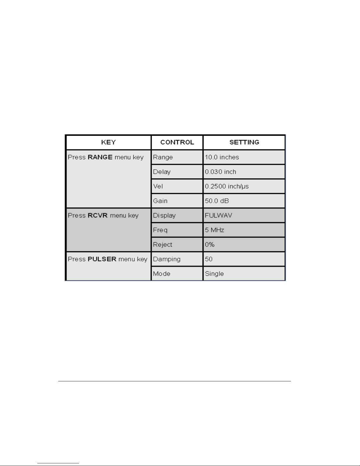
5.1.2 Instrument Calibration - 1 to 10” of Aluminum
Use the same procedure as the previous 0.5 inch steel test, but adjust the controls using 1-to-10
inch aluminum step blocks as the thin and thick steps. After calibrating at 1.0 inch and 10.0
inches, check at 5.0 inches for accuracy.
To select and change the following parameters, press the menu soft key below the selected
menu box, then rotate the SmartKnob™ or press the INC/DEC arrow keys to change the value.
The Sonic® 1200S/HR is now calibrated for 10 inches of aluminum at full screen range with
each major graticule division equal to 1 inch.
Different materials have different velocity attenuation and noise characteristics. The best
accuracy is obtained by using step blocks made from the same material as that being tested.
With practice, you may optimize the displayed ultrasonic signals by using the G ain, D amping,
Display, Frequency, and Reject control settings. The Reject setting can be used to improve the
display by eliminating small baseline signals (or noise).
An operator must recalibrate the thickness gauge when changing from IP mode to 1st back
wall reflection mode and to Multiple Echo mode to compensate for transducer offsets, surface
68 Chapter 5
Page 77
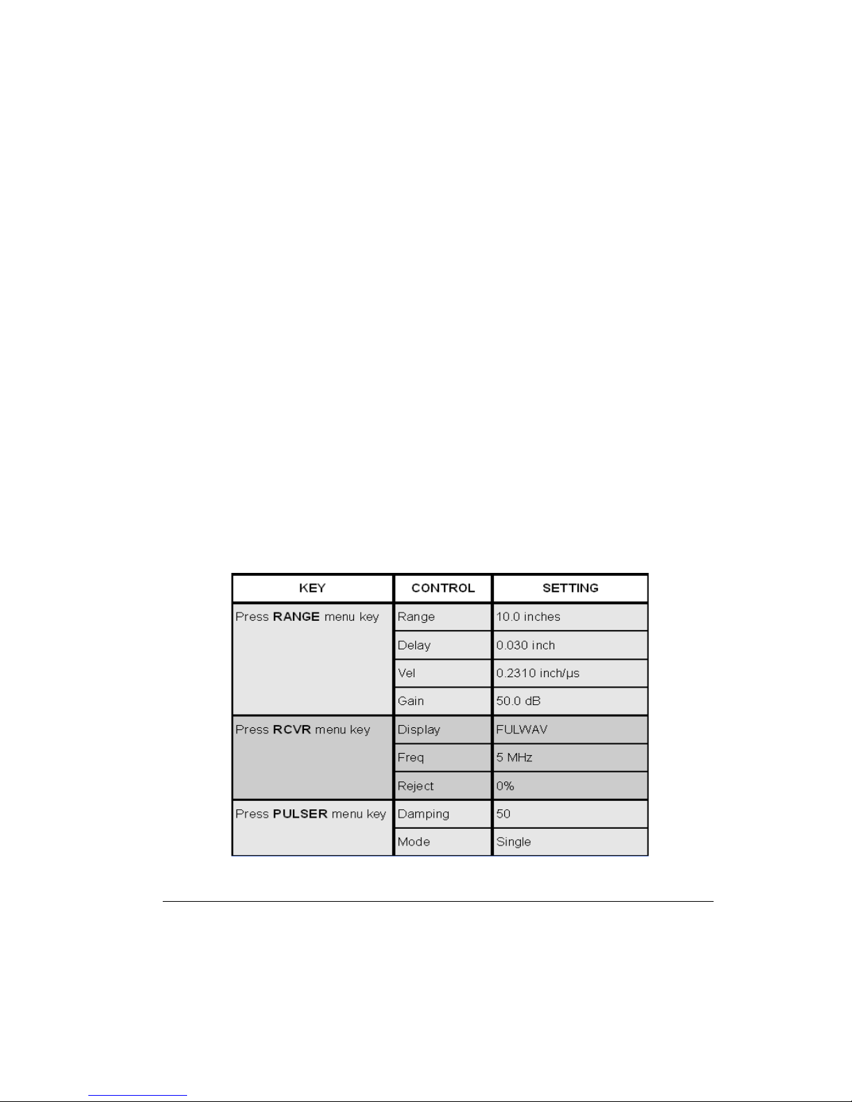
variations, and couplant thickness. In the Multiple Echo mode, t he ul trasonic echoes being
measured only include material thickness. Compensation for these offsets in the Multiple Echo
mode is not required.
5.1.3 Alternate Calibration Test Method - Multiple Echo, 1.0 to
10.0” of Steel
Notice that several multiple echo signals can be observed during the thickness calib ration and
testing. These echoes can be used to calibrate over a wider range than when using the first echo
technique. This method is especially useful if there is only one known thickness available.
For example, using only a 1 inch steel block (B1 Block), calibration of 1 to 10 inches or more
can be performed. In highly attenuative materials, (that is, cast materials), it may not be
possible to obtain multiple echoes over the desired thickness range, limiting this technique.
The same accessories (transducer, cable, couplant) are used except a block of only one known
thickness is required, such as a B1 Block with a 1 inch thickness.
1. Connect the transducer by cable to either instrument BNC.
2. Turn on instrument power and adjust the operating controls as follows:
To select and change the following parameters, press the menu soft key below the selected
menu box, then rotate the SmartKnob™ or press the INC/DEC arrow keys to change the value.
Applications 69
Page 78
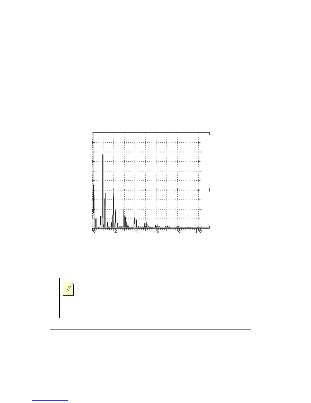
3. Place the transducer (with couplant) on the 1.0 inch thickness portion of the test block and
press the RANGE menu key.
4. Press DELAY menu soft key and rotate SmartKnob™ to line up the 1st echo on #1
graticule line.
5. Press VEL menu soft key and rotate SmartKnob™ to line up the 5th echo with #5 graticule
line.
6. Repeat steps 3 - 5 until both echoes line up. All 10 echoes sh ould then line up with a
graticule line, as shown in Figure 5-3. If they do, the instrument is calibrate d for 1.0 to
10.0 inches. If not, repeat calibration.
Figure 5-3: Multiple Echoes From 1.0 Block
5.1.4 Digital Thickness Calibration for Contact Transducers
Adjust the operating controls as follows:
To select and change the following parameters, press the menu soft key below the
selected menu box, then rotate the SmartKnob™ or press the INC/DEC arrow keys to
change the value. These settings are approximate and may vary due to the different types of
transducers used.
70 Chapter 5
Page 79
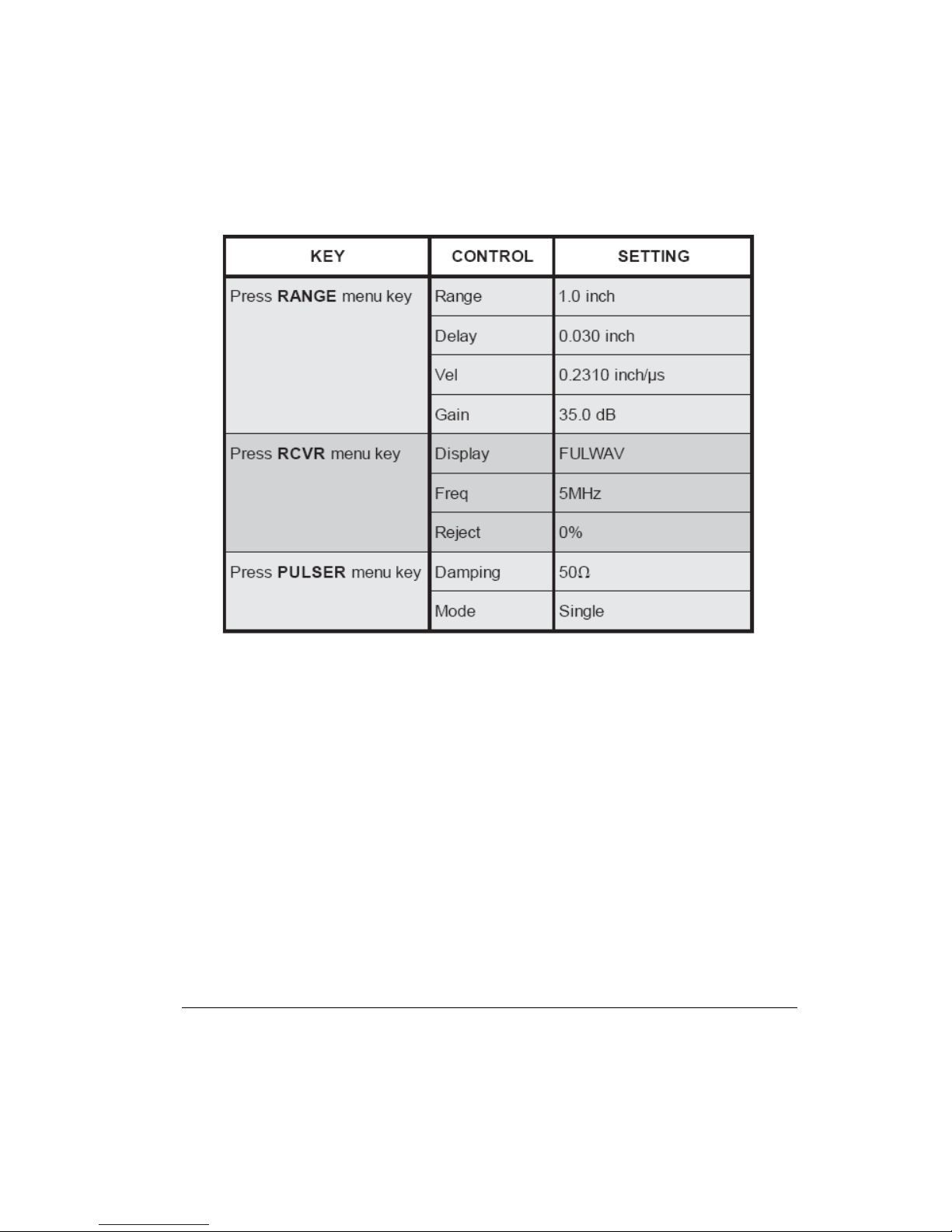
1. Place couplant on the step block and position the transducer on the thinnest (0.100) step.
2. Press RCVR menu key, then DISPLAY menu soft key, and rotate the SmartKnob™ to
select HALF-. Observe the signals and select “+” or “-” depending upon best signal
display.
3. Adjust Delay by pressing the RANGE menu key, then DELAY menu soft key, and rotate
the SmartKnob™ to line up the leading edge of the first echo on the No. 1 graticule line.
4. Adjust Gain by pressing the GAIN menu soft key, and rotate the SmartKnob™ to increase
the first echo amplitude to approximately 80% of full screen height (see Figure 5-4).
5. Move the transducer to the thickest (0.500) step and press the RANGE menu key, then
select the VEL menu soft key, and rotate the SmartKnob™ to line up the leading edge of
the first echo on the #5 graticule line (see Figure 5-5).
6. Repeat steps 1 - 5 to verify that both the 0.100 and 0.500 inch signals line up.
7. The instrument should now be calibrated for 1.0 inch of steel across the full screen width.
Each major graticule division corresponds to 0.100 inch of steel.
Applications 71
Page 80
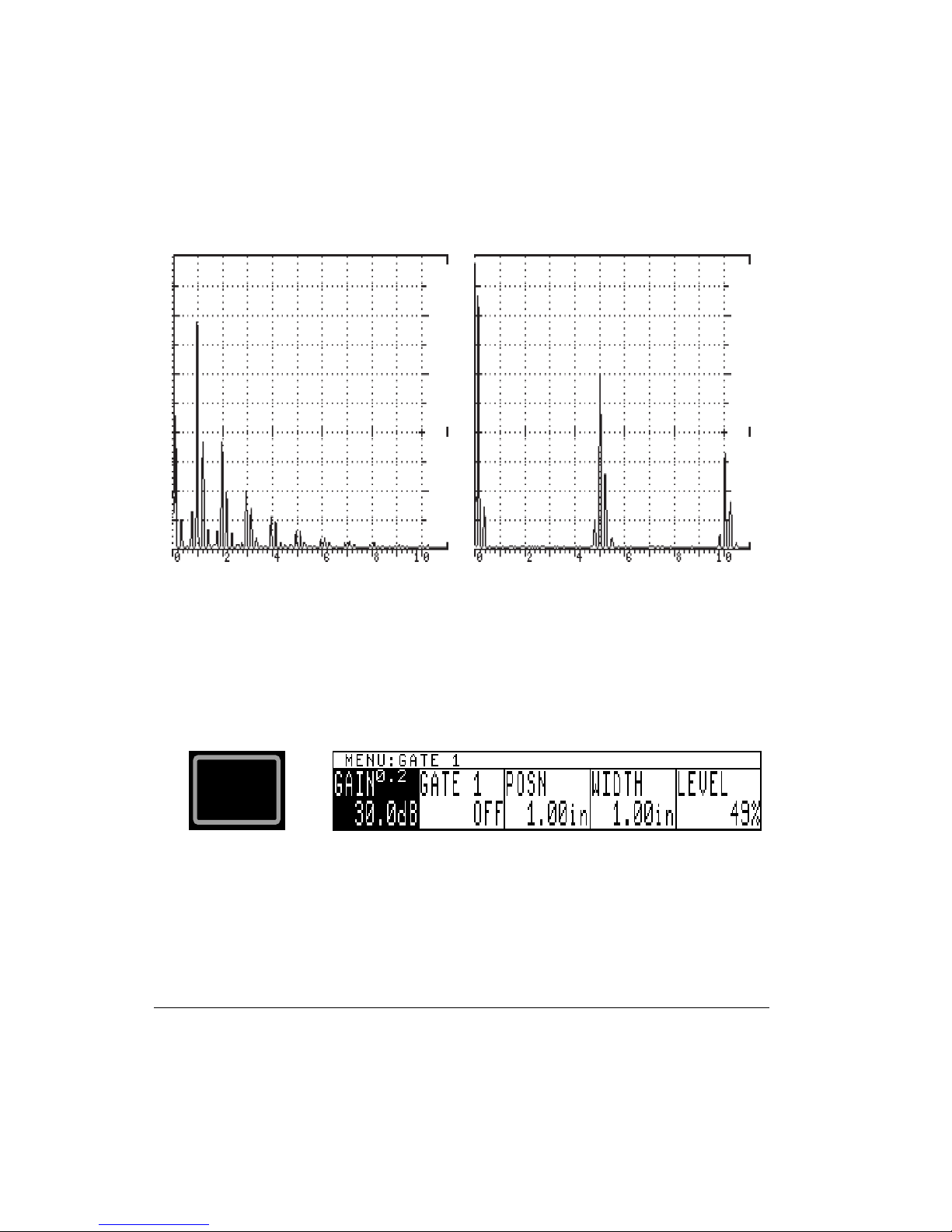
8. Check the 0.200, 0.300 and 0.400 inch steps. If they line up, the Sonic
calibrated. If not, repeat calibration steps 1 - 5.
Figure 5-4: Echo From 0.100 Step and Figure 5-5: Echo From 0.500 Step
®
1200S/HR is
5.1.5 Digital Thickness Measurement From the Initial Pulse to
the 1st Back Wall Reflection
Press the GATE1 menu key and the following menu will appear. This menu provides
changeable parameters, such as Polarity, Position, Width, and Level, for either flaw or
thickness measurements of Gate1.
GATE 1
For thickness measurements, adjust the controls as follows:
1. To enable Gate1, press GATE1 menu key again and rotate the SmartKnob™ to select the
“+” Gate1 alarm.
2. Press the Gate LEVEL menu soft key and rotate the SmartKnob™ to the desired screen
height, such as 40%.
72 Chapter 5
Page 81
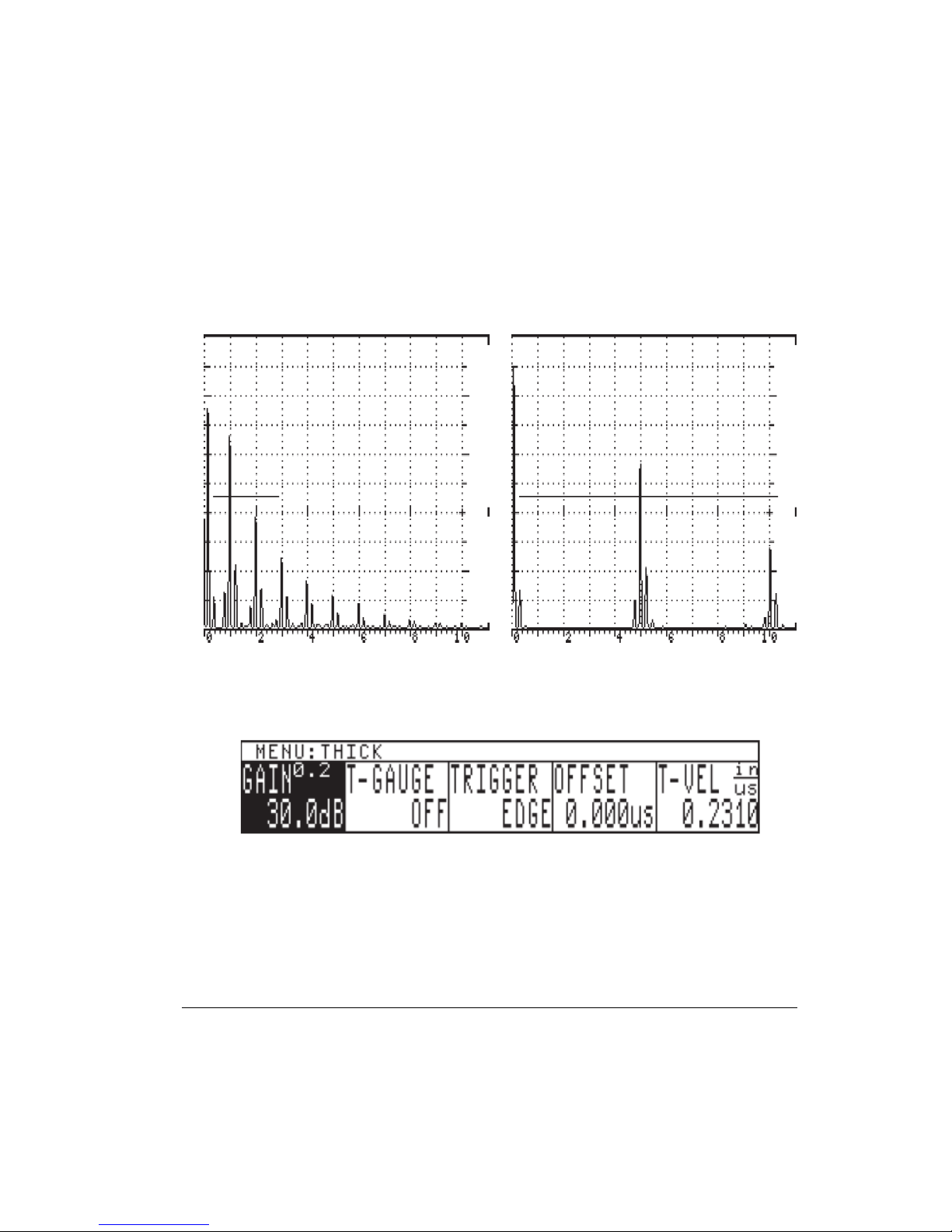
3. Press the Gate POSN menu soft key and rotate the SmartKnob™, or press the POSN menu
soft key repeatedly, to adjust the Gate position so that the start of the gate is to the left of
the thinnest (0.100 inch) step (see Figure 5-6).
4. Press the Gate WIDTH menu soft key and rotate the SmartKnob™, or press the WIDTH
menu soft key repeatedly, to adjust the Gate width to full screen or to the right of the
thickest step (0.500 inch).
Figure 5-6: Echo From 0.100 Step and Figure 5-7: Echo From 0.500 Step
5. Press the THICK menu key, then the T-GAUGE softkey, and the following menu will
display.
6. Use the SmartKnob
TRIGGER softkey and rotate the SmartKnob
™
to toggle through the selections. Select AIP - 1st. Press the
™
to toggle between peak or leading edge
triggering for thickness measurements. Select EDGE.
7. Place the transducer on the thickest step (0.500 inch of steel), press the THK CAL softkey,
and rotate the SmartKnob
™
until the THK CAL value for CAL PT1 reads 0.500 inch.
Press the ENTER key to log this value.
Applications 73
Page 82

8. Place the transducer on the thinnest step (0.100), press the THK CAL softkey and rotate
™
the SmartKnob
until the THK CAL value for CAL PT2 reads 0.100 inch. Press the
ENTER key to log this value.
9. Calibration is now done. Check the 0.200, 0.300, and 0.400 inch step s. If the thickness
readings are correct, the thickness gauge is calibrated. If the thickness gauge is not
calibrated, repeat calibration steps 5 through 8.
5.2 Dual Transducer Thickness Testing
Dual (pitch/catch) transducers produce better results for measuring thin (0.030 inch) materials
or rough and corroded metals in the 0.050 inch to 5.00 inch range. Th ey can also be used on
smooth materials to more than 10 inches.
The following accessories are required for this setup procedure:
STEP BLOCK — Sonic
TRANSDUCER — Harisonic
®
#1920105.00 steel step block or equal (0.100 to 0.500 inch).
®
J4MD (¼ in. 5 MHz).
COUPLANT — Use a couplant that “fills in” the surface. On smooth surfaces, use
thinner couplants (water, light oil, or mineral oil). On rough surfaces, the Sonic
couplant (P/N #3317450) is more appropriate.
5.2.1 Instrument Calibration - 0.100 to 0.500 Inches Steel
1. Connect the two transducer leads into both BNC connectors.
2. Turn instrument power on.
3. Set the Sonic
selecting the MODE menu soft key.
4. Adjust the operating controls as follows:
To select and change the following parameters, press the menu soft key below the selected
®
1200S/HR for Dual mode by pressing the PULSER menu key and then
®
X30S
74 Chapter 5
Page 83
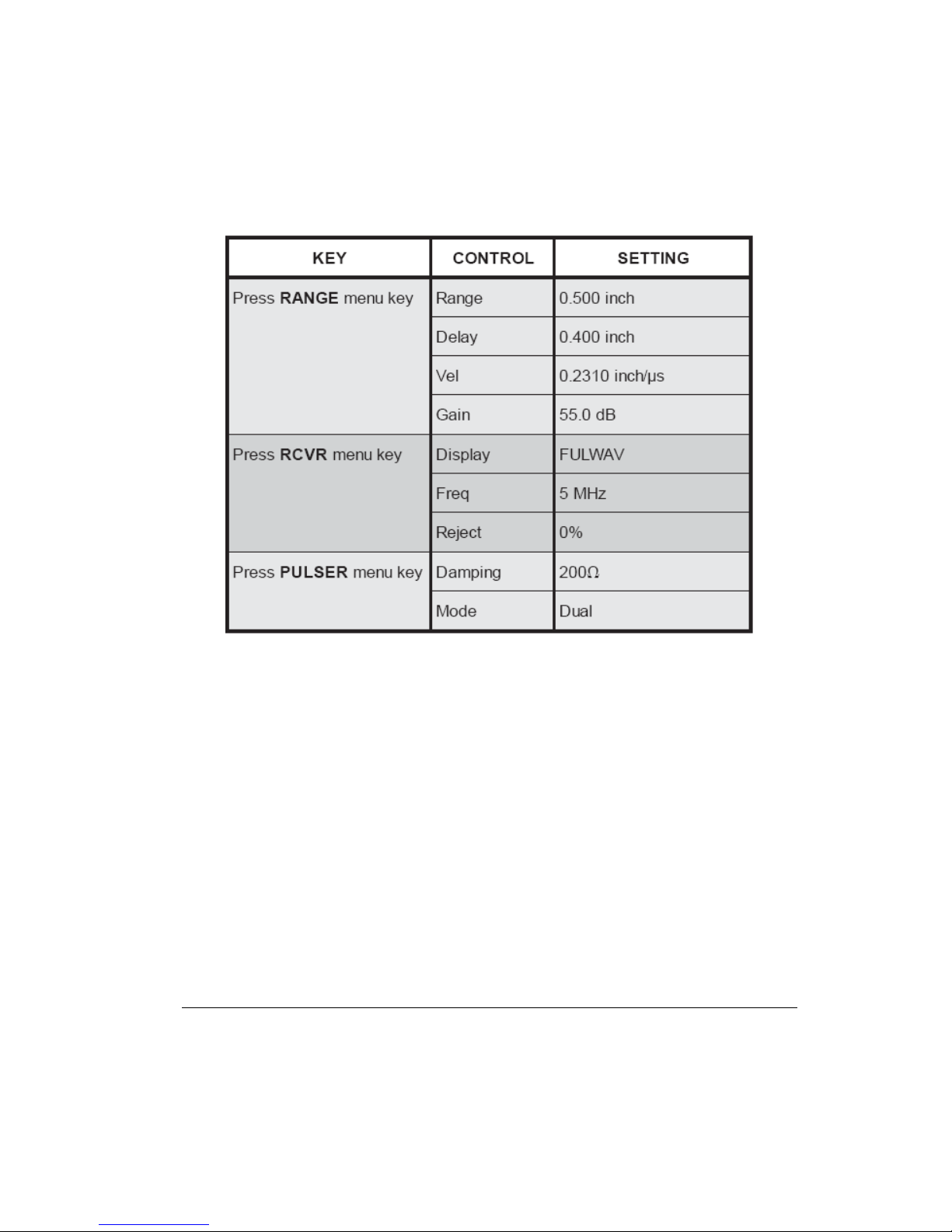
menu box, then rotate the SmartKnob™ or press the INC/DEC arrow keys to change the value.
5. Place X30S couplant on the step block and position the transducer on the thinnest (0.100)
step.
6. Press the RCVR menu key, then the DISPLAY menu soft key, and rotate the SmartKnob™
to select HALF-. Observe the signals and select “+” or “-” depending upon whi ch signal
displays the largest amplitude of the first cycle (see Figure 5-8).
7. Adjust Delay by pressing the RANGE menu key, then the DELAY menu soft key, and
rotate the SmartKnob™ to line up the leading edge of the first echo on the #2 graticule
line.
8. Adjust Gain by pressing the GAIN menu soft key, and rotate the SmartKnob™ to increase
the first echo amplitude to approximately 70% of full screen height (refer to Figure 5-8).
9. Move the transducer to the thickest (0.500 inch) step. Adjust the Velocity by pressing the
RANGE menu key, the VEL menu soft key, and rotate the SmartKnob™ to line up the
leading edge of the first echo on the last graticule line (refer to Figure 5-9).
10. Repeat steps 7 - 9 to verify that both the 0.100 and 0.500 inch signals line up.
11. Check the 0.200, 0.300. and 0.400 inch steps. If they line up, the Sonic
®
1200S/HR is
calibrated. If they do not line up closely, repeat calibration steps 5 through 9.
Applications 75
Page 84
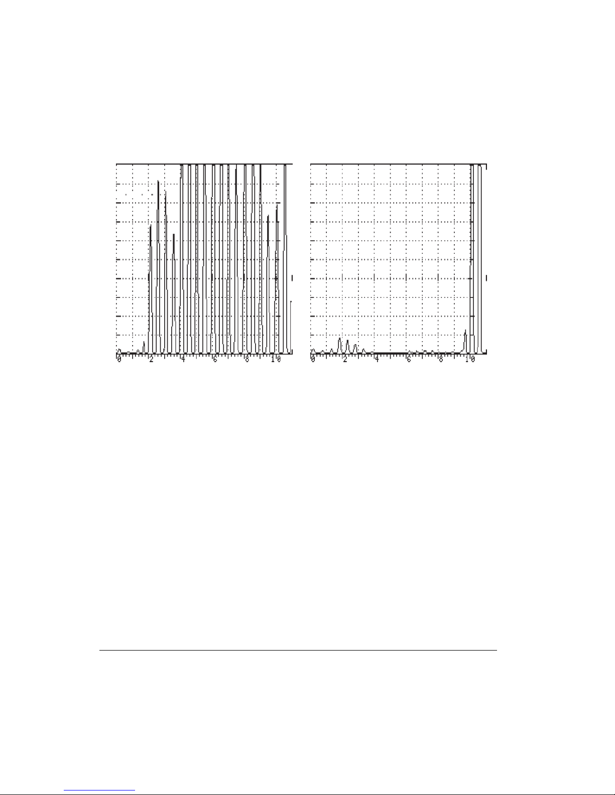
12. The Sonic
®
1200S/HR is now calibrated for steel from 0.100 inch to 0.500 inch This
method provides an accurate test over this range.
Figure 5-8. Pitch-Catch Echo from a 0.100 Step Block
Figure 5-9. Pitch-Catch Echo from a 0.500 Step Block
5.2.2 Instrument Calibration - 1.0 to 10.0 Inches of Steel
Use the same procedure as the previous 0.100 to 0.500 inch steel test, but adjust the controls
using 1 to 10 inch steel step blocks as the thin and thick steps. After calibrating at 1.0 inch and
10.0 inches, check at 5.0 inches for accuracy.
To select and change the following parameters, press the menu soft key below the selected
menu box, then rotate the SmartKnob™ or press the INC/DEC arrow keys to change the value.
76 Chapter 5
Page 85
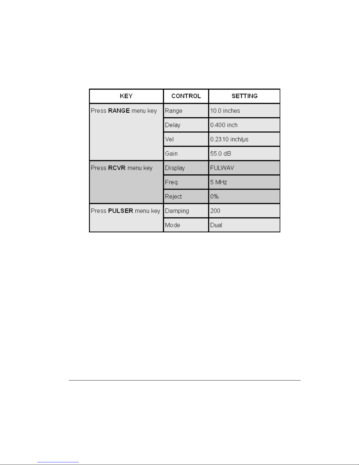
®
The Sonic
major graticule division equal to 1 inch.
Different materials will have different velocity, attenuation, and noise characteristics. The best
accuracy will be obtained by using step blocks made from the same material as that being
tested.
With practice, you may optimize the displayed ultrasonic signals by using the Gain, D amping,
Display, Frequency, and Reject control settings. The Reject setting can be used to improve the
display by eliminating small baseline signals (or noise).
1200S/HR is now calibrated for 10 inches of steel at full screen range with each
5.2.3 Alternate Calibration Method - Multiple Echo, 1” - 10”
Steel
The multiple echo calibration method can be used with t he dual transducer. This met hod is
especially useful if there is only one known thickness available.
For example, using only a 1 inch steel block (B1 Block), calibration of 1 to 10 inches or more
Applications 77
Page 86
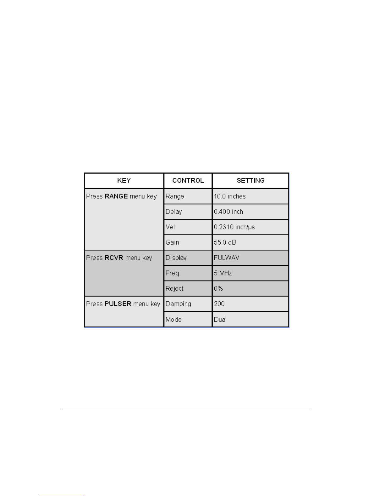
can be performed. In highly attenuative materials (for example, cast materials), it may not be
possible to obtain multiple echoes over the desired thickness range, thus limiting this
technique.
The same accessories (transducer, cable, couplant) are used, except a block of only one known
thickness is required, such as a B1 block with 1 inch thickness.
1. Connect the two transducer leads into both BNC connectors.
2. Turn on instrument power and adjust the operating controls as follows:
To select and change the following parameters, press the menu soft key below the selected
menu box, then rotate the SmartKnob™ or press the INC/DEC arrow keys to change the value.
3. Place the transducer (with couplant) on the 1.0 inch thickness portion of the test block and
press the RANGE menu key.
4. Press DELAY menu soft key and rotate the SmartKnob™ to line up the 1st echo on the #1
graticule line.
5. Press VEL menu soft key and rotate the SmartKnob™ to line up the 5th echo with the #5
graticule line.
78 Chapter 5
Page 87
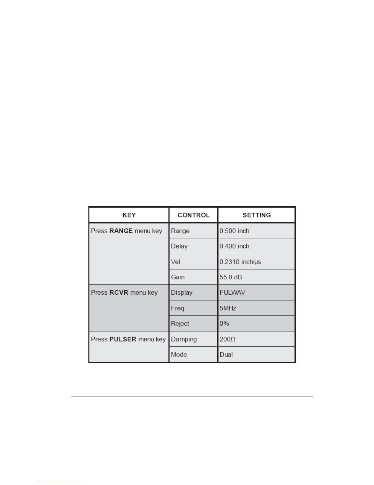
6. Repeat steps 4 and 5 until both echoes line up. All 10 echoes should then lin e up with a
graticule line. If they do, the instrument is calibrated fo r 1.0 to 10.0 inches. If not, repeat
calibration.
7. After calibration, you are ready to start testing for flaws. If the calibration block surfaces
are similar to the test material, you can proceed. If the surface (inner or outer) is rougher
or curved, you will need to adjust the Gain to acquire signals back up to about 70%.
Rough outer surfaces will also cause echoes after the initial pulse which restricts the
resolution of thin surfaces. Always make sure that the display signals are clear and “make
sense” before proceeding with the test.
5.2.4 Dual Element High/Low Digital Thickness Calibration
Adjust the operating controls as follows:
To select and change the following parameters, press the menu soft key below the selected
menu box, then rotate the SmartKnob™ or press the INC/DEC arrow keys to change the value.
Applications 79
Page 88
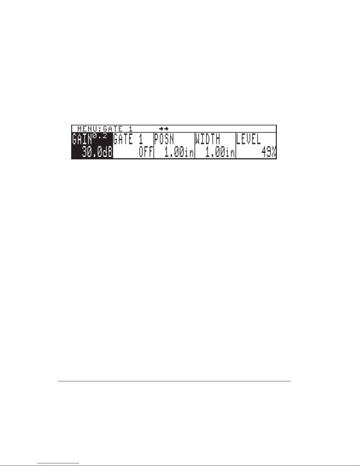
5.2.5 Thickness Measurement from Initial Pulse to 1st Back
Wall Reflection
Press the GATE1 menu key and the following menu will appear. This menu provides
changeable parameters, such as Polarity, Position, Width, and Level, for either flaw or
thickness measurements of Gate1.
For thickness measurements, adjust the controls as follows:
1. To enable Gate1, press GATE1 menu key again and rotate the SmartKnob™ to select the
“+” Gate1 alarm.
2. Press the Gate LEVEL menu soft key and rotate the SmartKnob™ to the desired screen
height, such as 40%.
3. Press the Gate POSN menu soft key and rotate the SmartKnob™, or press the POSN menu
soft key repeatedly, so that the start of the gate is to the left of the thinnest step (0.100
inch). (Please refer to Figure 5-10).
80 Chapter 5
Page 89
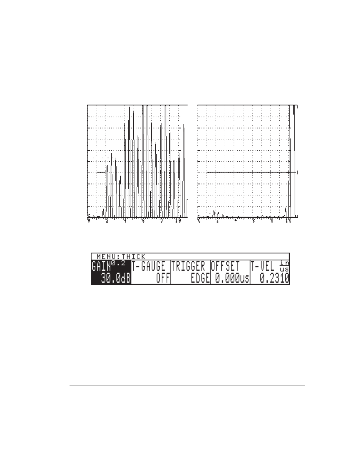
4. Press the Gate WIDTH menu soft key, and rotate the SmartKnob™, or press the WIDTH
menu soft key repeatedly, to adjust the Gate width to full screen or to the right of the
thickest step (0.500 inch). (Please refer to Figure 5-11).
5. Press the THICK menu key and the follo wing menu will display. Press the T-GAUGE
menu soft key, and use the UP/DOWN arrow keys to toggle through the selections. Select
A IP - 1
st
.
6. Press the TRIGGER softkey and rotate the SmartKnob
leading edge triggering for thickness measurements. Select EDGE.
7. Place the transducer on the thickest step (0.500 inch of steel), press the THK CAL softkey,
and rotate the SmartKnob
Press the ENTER key to log this value.
8. Place the transducer on the thinnest step (0.100), press the THK CAL softkey and rotate
the SmartKnob
ENTER key to log this value.
9. Calibration is now done. Check the 0.200, 0.300, and 0.400 i nch steps. If the thickness
readings are correct, the thickness gauge is calibrated. If the thickness gauge is not
calibrated, repeat calibration steps 5 through 8.
™
to toggle between peak or
™
until the THK CAL value for CAL PT1 reads 0.500 inch.
™
until the THK CAL value for CAL PT2 reads 0.100 inch. Press the
Applications 81
Page 90
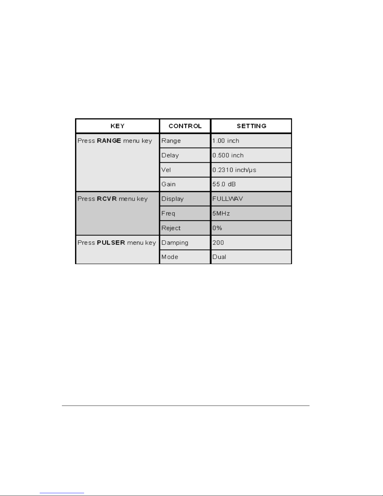
5.2.6 Thickness Using Multiple Echoes From the 1st Back W all
to 2nd Back Wall Reflection, Echo-to-Echo
Adjust the operating controls as follows:
To measure between echoes, both Gate 1 and Gate 2 are used for thickness measurements.
Gate 1 position (start) must be to the left of the thinnest step (echo) for thickness
measurements. The width must be wide enough to cover the area where the 1st back wall echo
will appear (see Figure 5-12).
Gate 2 position (start) must be to the ri ght of the 1st back wall echo and to the left of the
thinnest 2nd back wall echo for accurate thickness measurements. The width of Gate 2 must be
82 Chapter 5
Page 91
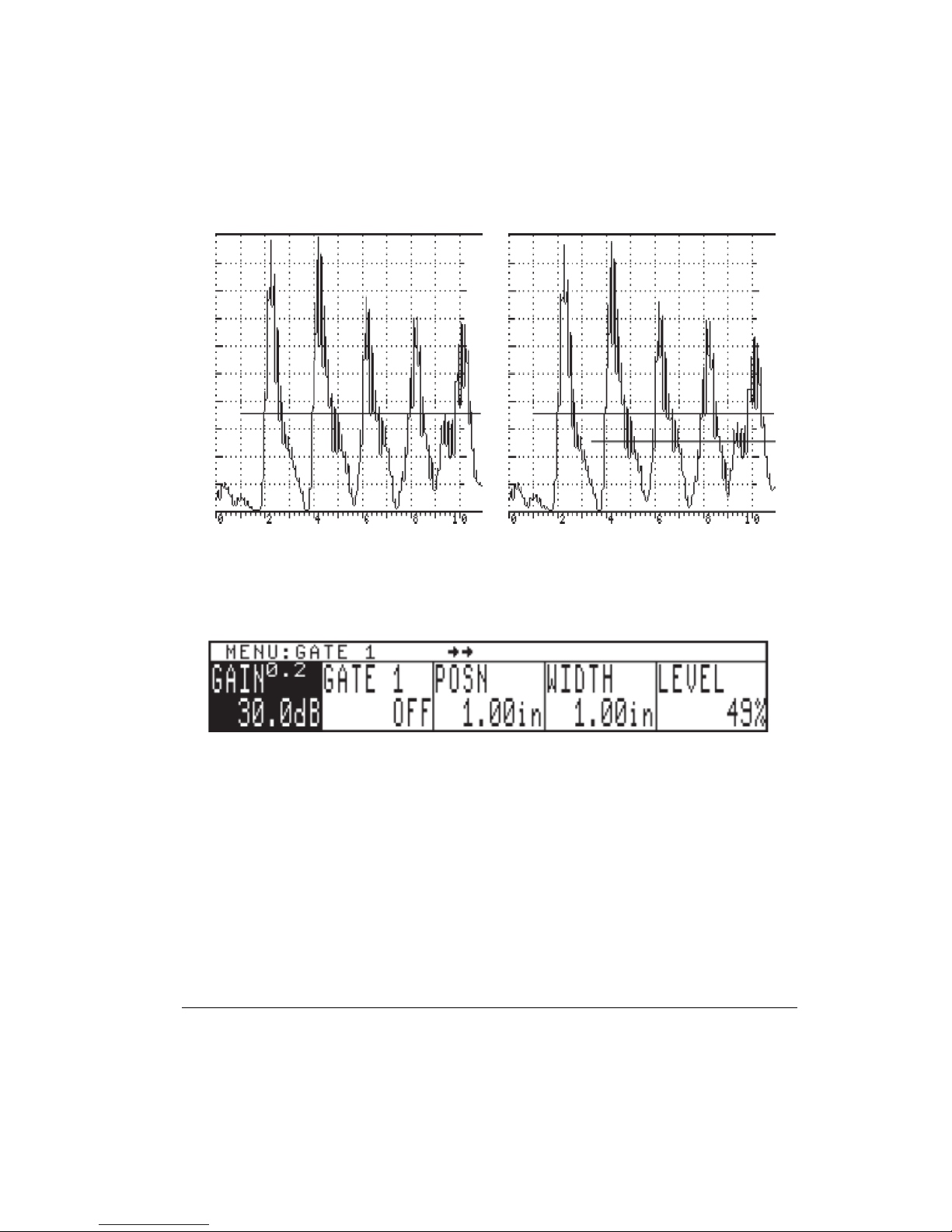
wide enough to cover the area where the 2nd back wall echo will appear (see Figure 5-13).
Figures 5-12 and 5-13
Press GATE1 menu key and the following menu will appear. This menu provides changeable
parameters, such as Polarity, Position, Width, and Level, for either flaw or thickness
measurements of Gate1.
For thickness measurements, adjust the controls as follows.
1. To enable Gate1, press GATE1 menu key again and rotate the SmartKnob™ to select the
“+” Gate1 alarm.
2. Press the Gate LEVEL menu soft key and rotate the SmartKnob™ to the desired screen
height, such as 35%.
3. Press the Gate POSN menu soft key and rotate the SmartKnob™, or press the POSN menu
soft key repeatedly, so that the start of the gate is to the left of the thinnest step (0.200
inch). (Please refer to Figure 5-14).
4. Press the Gate WIDTH menu soft key and rotate the SmartKnob™, or press the WIDTH
menu soft key repeatedly, to adjust the Gate width until it goes past or through the 1st echo
from the thinnest step (see Figure 5-15).
Applications 83
Page 92
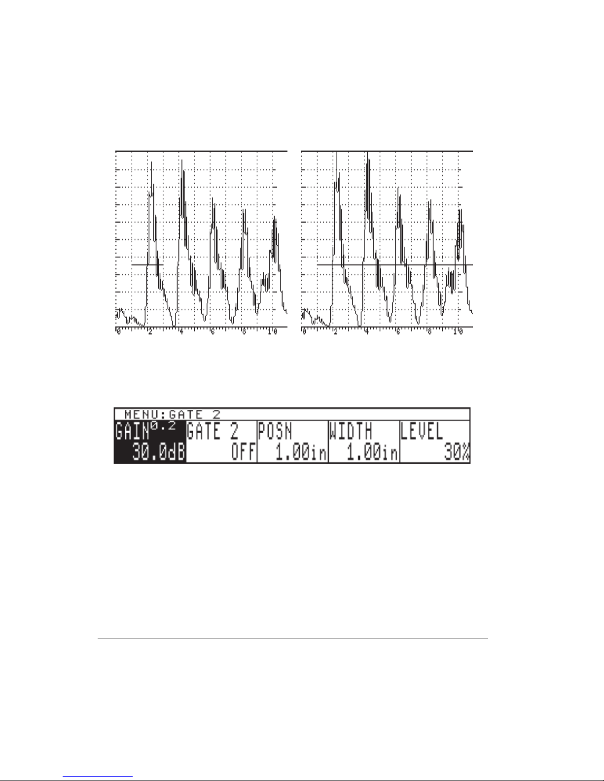
The Gate width must extend past the thickest step in the calibration procedure.
Figures 14 and 15
Press the GATE2 menu key and the following menu will appear. This menu provides
changeable parameters, such as Polarity, Position, Width, and Level, for either flaw or
thickness measurements of Gate2.
For this application, Gate2 is used for thickness.
1. To enable Gate2, press the GATE2 menu key again and rotate the SmartKnob™ to select
the “+” Gate2 alarm.
2. Press the Gate LEVEL menu soft key and rotate the SmartKnob™ to the desired screen
height, such as 25%.
3. Press the Gate POSN menu soft key and rotate the SmartKnob™, or press the POSN menu
soft key repeatedly, so that the start of the gate is to the left of the 2nd back wall echo, o r
just to the right side of the 1st back reflection (see Figure 5-16).
84 Chapter 5
Page 93
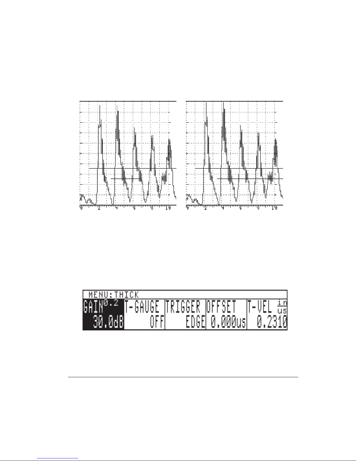
4. Press the Gate WIDTH menu soft key and rotate the SmartKnob™, or press the WIDTH
menu soft key repeatedly, to adjust the Gate width to go past or through the 2nd back wall
echo (see Figure 5-17).
Figure 16 and 17
5. For echo-to-echo measurements on thinner material than 0.500 inch, the Gate 2 po sition
(start) and width must be adjusted for the thinnest echo-to-echo measurement, such as
0.200 inch (see Figure 5-18).
6. Gate 2 must start prior to the 2nd back wall echo (left side of echo) and the width must be
wide enough so the 2nd back wall echo passes through it (see Figure 5-18).
7. Press the THICK menu key and the follo wing menu will display. Press the T-GAUGE
menu soft key, and use the UP/DOWN arrow keys to toggle through the selections. Select
Auto Echo - Echo.
Applications 85
Page 94
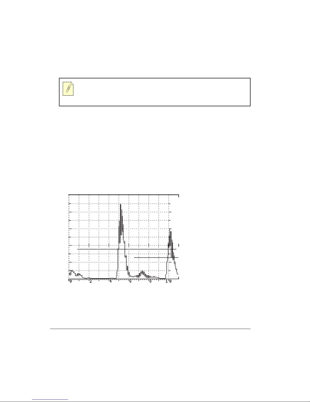
Gate 1 must start prior to the 1st echo (left side of echo) and the width must be wide
enough so the 1st back wall echo passes through it.
8. Place the transducer on the thinnest step (0.200 inch). Verify proper Gate1 and Gate2
positioning, as above (the thickness gauge starts the measurement with the 1st echo to
break Gate1, and stops the measurement with the 1st echo to break Gate2). Press the THK
CAL softkey, and rotate the SmartKnob until the THK CAL value for CAL PT1 reads
0.200 inch. Press ENTER to log this value (Please refer to Figure 5-19).
9. Place the transducer on the thickest step (0.500 inch of steel). Verify proper Gate1 and
Gate2 positioning, as above (a slight adjustmen t of the Gate2 position may be required to
prevent triggering on unwanted signals), press the THK CAL softkey, and rotate the
SmartKnob until theTHK CAL value for CAL PT2 reads 0.500 inch. Press ENTER to log
this value.(Please refer to Figure 5-20).
10. Calibration is now done. Check other thickness values to verify; if the thickness readi ngs
are correct, the thickness gauge is calibrated. If the thickness gauge is not calibrated,
repeat calibration steps 5 through 14 (velocity of the material under test).
86 Chapter 5
Page 95
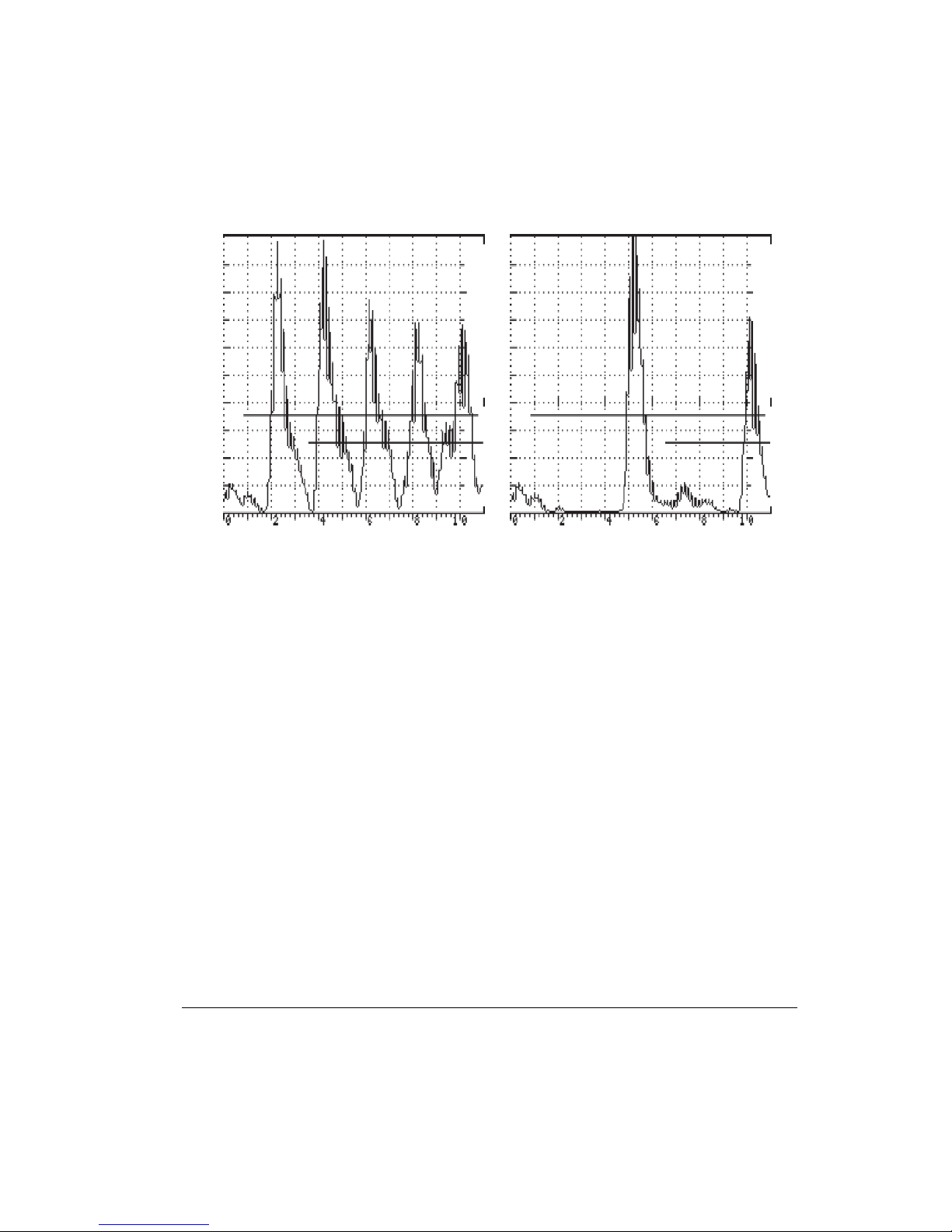
Figures 19 and 20
5.2.7 Manual Echo-to-Echo Mode Calibration
To cali brate the gage using Manual Echo-to-Echo mode, follow in structions for AUTO Echoto-Echo calibration (see above) and instead of calibrating thickness using PT1 and PT2, do as
follows:
1. From the THICK Menu, set VELOCITY according to nominal material velocity.
2. Place the transducer on the thin block and adjust OFFSET for the block value.
3. Place the transducer on the thick block and adjust the THICK VELOCITY for that value.
4. Repeat as necessary.
5.3 Delay Line Thickness Testing
In testing thin materials with smooth surfaces, the use of a wideband delay line transducer is a
good method. The delay through the plastic enables better resolution. Thicknesses do wn to
0.010 inch can be resolved, since the delay moves the echoes away from the initial pulse
ringing, as shown in Figure 5-21.
The range is limited by the delay in the plastic as the 2nd echo will interfere with the multiple
Applications 87
Page 96
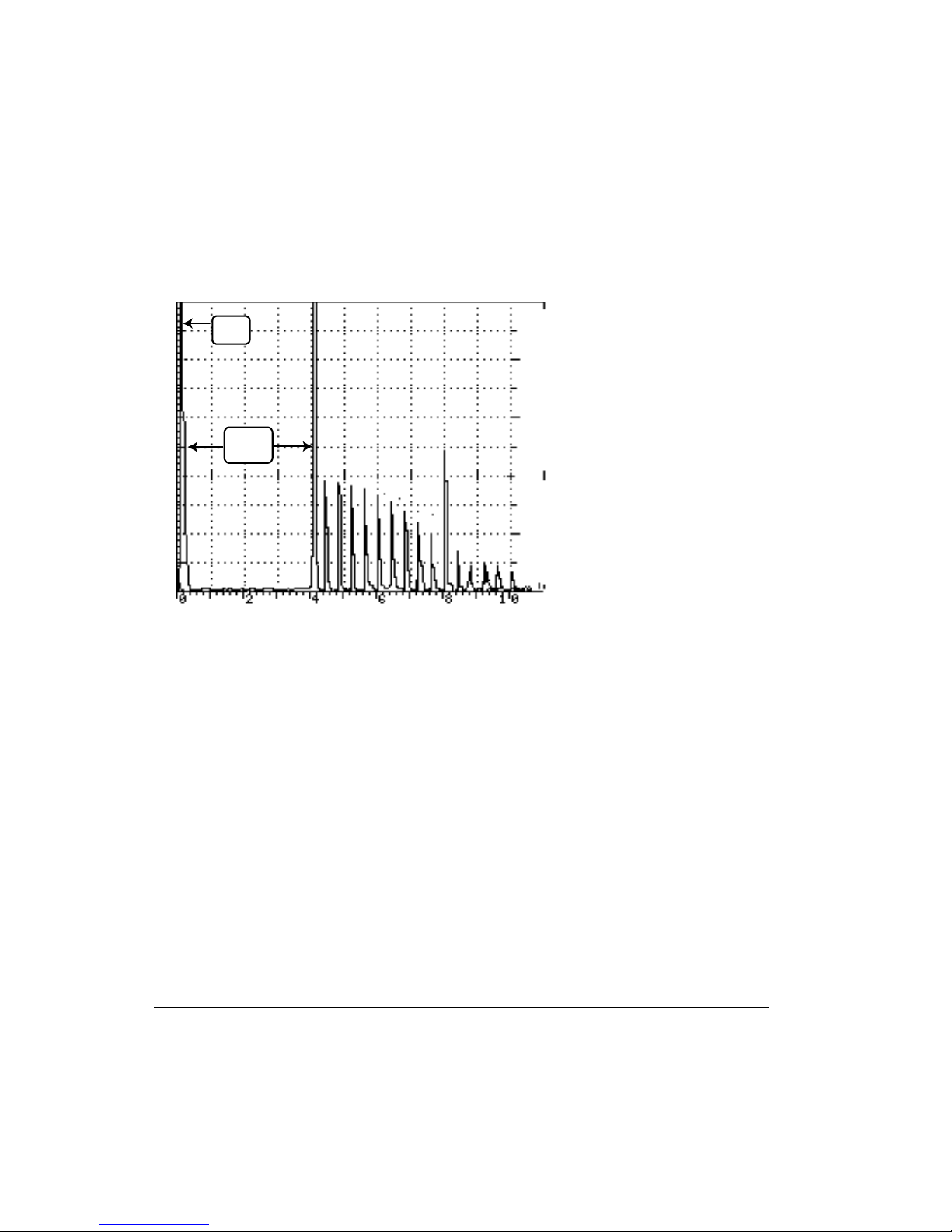
echoes. Usually the range is from 0.010 inch to 0.500 inch, but it can go up to 0.750 inch.
The measurement is made between the echoes (for best accuracy, the 1st and 2nd back echoes).
The thickness gauge offsets, and sound velocity must be recalibrated, each time the instrument
is powered up.
IP
DELAY
Figure 21: Delay Line Test Echoes
The following accessories are required for this procedure:
STEP BLOCK: Sonic
®
#1920105.00 Steel Step Block or equal (0.100, 0.200, 0.300,
0.400, 0.500 inch steps).
TRANSDUCER: A 10 MHz highly damped delay line transducer is usually the best
choice, but a 5 MHz transducer may be used if the material is above 0.050 inch.
Spectrum™ C17L is a good selection.
TRANSDUCER CABLE: Sonic
COUPLANT: A thin couplant is preferred, such as Sonic
®
BNC/Microdot (#9102894).
®
X30S couplant (#3317450),
mineral oil, light oil, or possibly water.
5.3.1 Instrument Calibration - 0.500” Thickness Range, Steel
1. Connect the transducer cable to the Spectrum™ C17L transducer and to either BNC
connector.
2. Turn on the instrument power, and adjust the operating controls as follows:
88 Chapter 5
Page 97
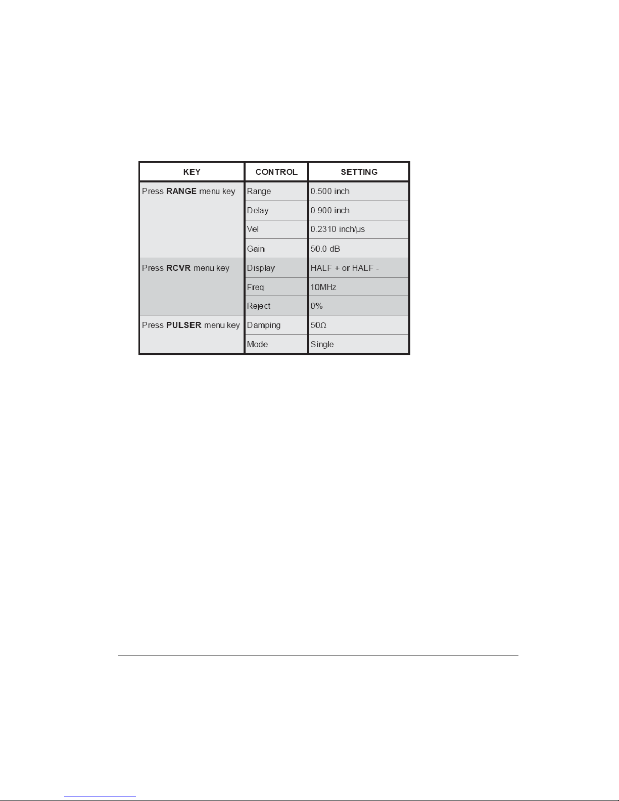
To select and change the following parameters, press the menu soft key below the selected
menu box, then rotate the SmartKnob™ or press the INC/DEC arrow keys to change the value.
3. Place couplant on the test block and position the transducer on the thinnest (0.100) step.
4. Press the RCVR menu key, then the DISPLAY menu soft key, and rotate the SmartKnob™
to select HALF-. Observe the signals and select “+” or “-” depending upon best signal
display.
5. Adjust Delay by pressing the RANGE menu key, then the DELAY menu soft key, and
rotate the SmartKnob™ to line up the leading edge of the first echo on the #2 graticule
line.
6. Adjust Gain by pressing the RANGE menu key, then GAIN menu soft key, and rotate the
SmartKnob™ to increase the first echo amplitude to approximately 70% of full screen
height, #7 line vertical (refer to Figure 5-22).
Applications 89
Page 98
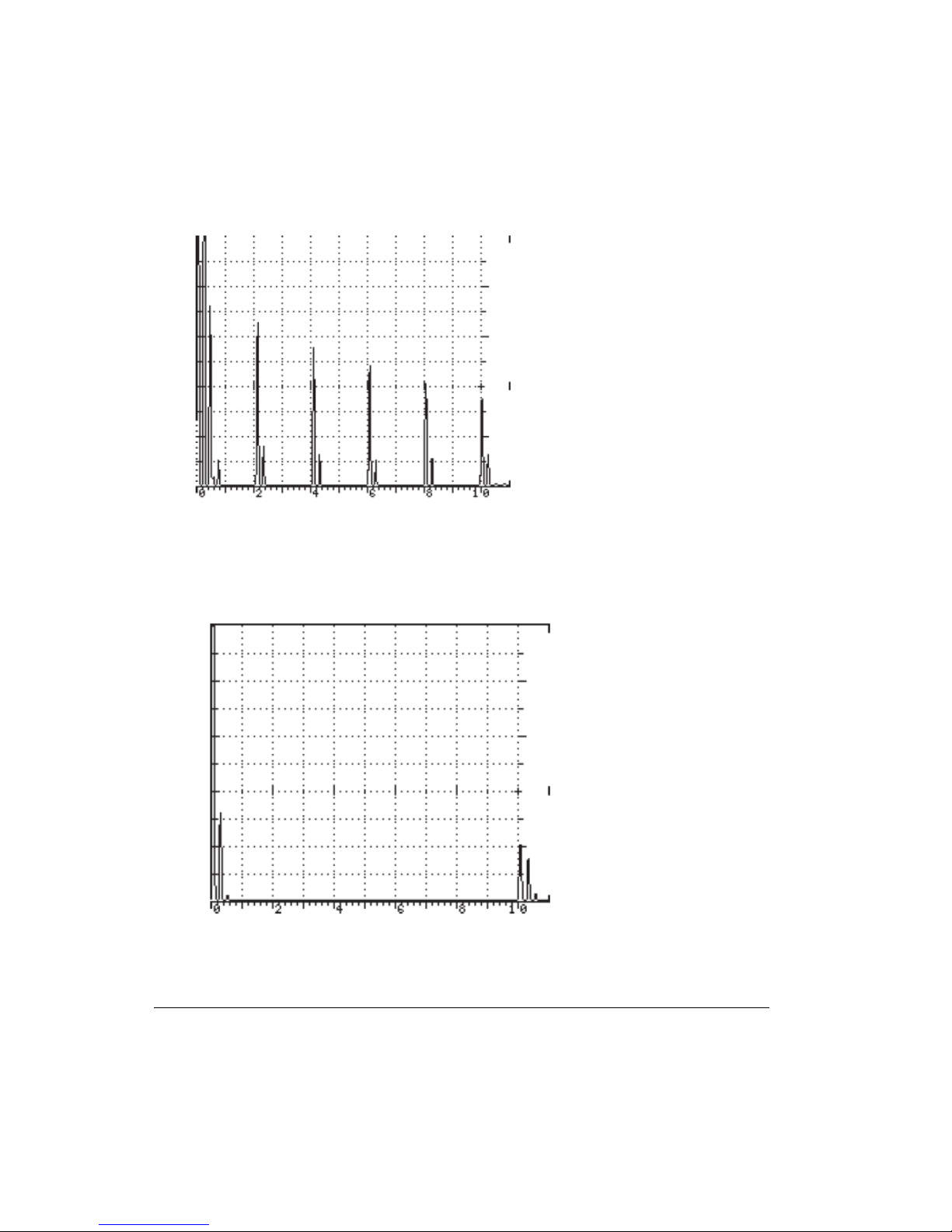
Figure 22: First Back Echo at 0.100”
7. Move the transducer to the thickest (0.500) step. Adjust the Velocity by pressing the
RANGE menu key, the VEL menu soft key, and rotating the SmartKnob™ to line up the
leading edge of the first echo on the last graticule line (refer to Figure 5-23).
Figure 23: First Back Echo at 0.500”
90 Chapter 5
Page 99
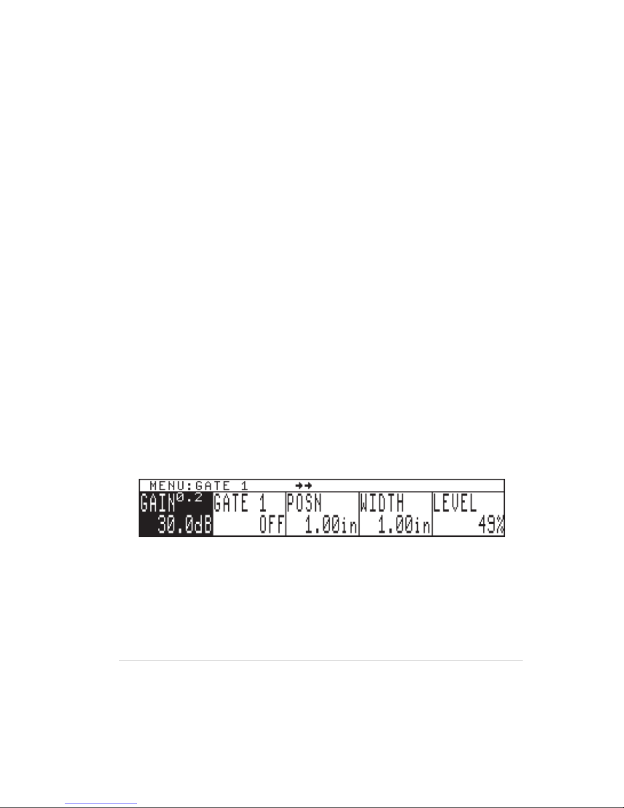
8. Repeat steps 4 - 8 to verify that both the0.100 and 0.500 inch signals line up.
®
9. Check the 0.200, 0.300 and 0.400 inch steps. If they line up, the Sonic
calibrated. If they do not line up closely, repeat calibration st eps 4 - 8.
1200S/HR is
5.3.2 Instrument Calibration - Other Ranges
The instrument is calibrated similarly for other ranges and materials. Use step blocks made of
the same test material and thickness range as the material being measured.
With practice, you may optimize the displayed ultrasonic signals by the use of Gain, Damping,
Display , and Reject controls. Reject controls can be used to improve the display by eliminating
small baseline signals or noise.
5.3.3 Instrument Calibration - Testing
When using the delay line method, the best results are obtained only when several multiples or
echoes are displayed. In some attenuative materials or plastics, only one back echo may be
obtained. In this case, the surface echo to 1st back echo signals can be used as a measurement,
but accuracy will not be quite as good.
5.3.4 Thickness Measurements From Delay Line Interface to
the 1st Back Wall Reflection
Press the GATE1 menu key and the following menu will appear. This menu provides
changeable parameters, such as Polarity, Level, Position, and Width, for either flaw or
thickness measurements of Gate1.
For thickness measurements, adjust the controls as follows.
1. To enable Gate1, press the GATE1 menu key again, and rotate the SmartKnob™ to select
the “+” Gate1 alarm.
2. Press the Gate LEVEL menu soft key and rotate the SmartKnob™ to the desired screen
height, such as 40%.
Applications 91
Page 100
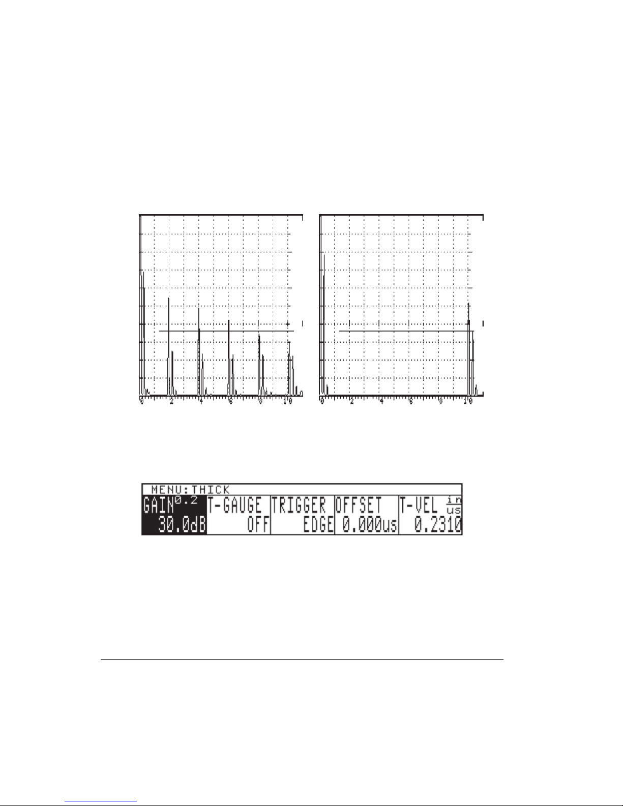
3. Press the Gate POSN menu soft key and rotate the SmartKnob™, or press the POSN menu
soft key repeatedly , so that the start of the gate is to the left of the thinnest (0.100 inch) step
(see Figure 5-24).
4. Press the Gate WIDTH menu soft key and rotate the SmartKnob™, or press the WIDTH
menu soft key repeatedly, to adjust the Gate width to full screen or to the right of the
thickest step (0.500 inch). (Please refer to Figure 5-25).
Figures 24 and 25
5. Press the THICK menu key and the following menu will display. Press the T-GAUGE
menu soft key, and use the UP/DOWN arrow keys to toggle through the selections. Select
A IP - 1
6. Press the TRIGGER softkey and rotate the SmartKnob
st
.
™
to toggle between peak or
leading edge triggering for thickness measurements. Select EDGE.
7. Place the transducer on the thickest step (0.500 inch of steel), press the THK CAL softkey,
and rotate the SmartKnob
™
until the THK CAL value for CAL PT1 reads 0.500 inch.
Press the ENTER key to log this value.
92 Chapter 5
 Loading...