

Page 1

µ-10/µ [mju:] 300/Stylus 300 DIGITAL
µ-20/µ [mju:] 400/Stylus 400 DIGITAL
B. DISASSEMBLY AND ASSEMBLY PROCEDURE
B. DISASSEMBLY AND ASSEMBLY
PROCEDURE
[1] REMOVAL OF FRONT COVER, BACK COVER .................................................... B-2
[2] REMOVAL OF TFT, PW-PCA, MC-PCA, FL-PCA .................................................. B-3
[3] REMOVAL OF VIEW FINDER, CCD UNIT, LENS UNIT ......................................... B-4
B-1 Ver.1
Page 2
µ-10/µ [mju:] 300/Stylus 300 DIGITAL
µ-20/µ [mju:] 400/Stylus 400 DIGITAL
B. DISASSEMBLY AND ASSEMBLY PROCEDURE
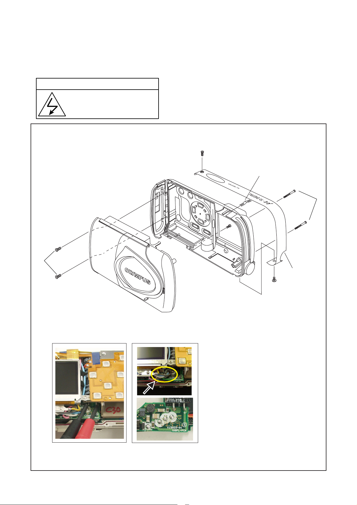
[1] REMOVAL OF FRONT COVER AND BACK COVER
Disassembly perform as follows (1, 2...) and assembly perform by reversing the disassembly steps (...2,1). Be sure to
discharge the main capacitor in procedure 9, then continue to disassembling.
! Beware of electric shock
Danger of electric shock.
Use a discharging tool to remove
the electrical charge before working.
1
7
8
4
11
6
5
3
2
910
1. MDL-Metal Screw 2
P
W
2. MDL-Metal Screw
3. MDL-Metal (adhesive)
4. Two screws 1.6x12.5
5. Two screws 1.6x4
6. Screw 1.4x3.5
7. Back Cover (two hooks)
8. F-B Contact
9. Discharge
B
G
10. Solder
11. Front Cover
B-2 Ver.1
Page 3

µ-10/µ [mju:] 300/Stylus 300 DIGITAL
µ-20/µ [mju:] 400/Stylus 400 DIGITAL
B. DISASSEMBLY AND ASSEMBLY PROCEDURE
[2] REMOVAL OF TFT, PW-PCA, MC-PCA AND FL-PCA
16
18
17
19
10
4
20
14
7
2
8
5
9
11
6
1. Two FPCs
1
13
2. TFT (tape)
3. Solder
3
12
R
B
15
B
R
R
4. SELF-PCA (tape)
5. Screw 1.6x1.6
6. Screw 1.4x3
7. MDL-Metal Screw
8. Screw 1.6x4
9. Three screws 1.6x3
10. B to B connector
11. Body Frame
12. FPC
13. B to B connector
14. Lens and CCD unit
15. Solder
16. Two screws 1.6x4
17. PW-PCA
18. Two screws 1.6x3.5
19. MC-PCA
BR
BO
20. FL-PCA
B-3Ver.1
Page 4

B. DISASSEMBLY AND ASSEMBLY PROCEDURE
r
[3] REMOVAL OF VIEW FINDER, CCD UNIT AND LENS UNIT
1
µ-10/µ [mju:] 300/Stylus 300 DIGITAL
µ-20/µ [mju:] 400/Stylus 400 DIGITAL
4
1. Screw
2. View Finder
3. Three screws
4. CCD unit
5. CCD Rubber
6. LPF
7. Lens unit
2
3
5
6
7
CCD
CCD Rubbe
Lens
LPF
Fixing the aspect of View Finder and Lens unit
1. Finder lens should be set down by rotating F Gear.
2. Rotate F Gear more, to the position which can insert a pin.
(F Gear may be damaged if F Gear is rotated too much.)
3. Insert a pin to keep the position of F Gear.
4. Fix Veiw Finder to Lens unit.
5. Check the position of F Gear.
B-4 Ver.1
 Loading...