

Page 1

µ-10/µ [mju:] 300/Stylus 300 DIGITAL
C. ADJUSTMENT METHOD
µ-20/µ [mju:] 400/Stylus 400 DIGITAL
C. ADJUSTMENT METHOD
[1] TABLE FOR SERVICING TOOLS .......................................................................... C-2
[2] EQUIPMENT ...........................................................................................................C-2
[3] ADJUSTMENT ITEMS AND ORDER......................................................................C-2
[4] SETUP .................................................................................................................... C-2
[5] CONNECTING THE CAMERA TO THE COMPUTER
/ DRIVER INSTALLATION ...................................................................................C-3
[6] ADJUST SPECIFICATIONS.................................................................................... C-3
1. ZOOM ADJUSTMENT ........................................................................................C-4
2. CCD BLOCK ADJUSTMENT .............................................................................C-4
2-1. MECHANICAL SHUTTER ADJUSTMENT ................................................ C-4
2-2. CCD DEFECT ADJUSTMENT ................................................................... C-4
3. COLOR ADJUSTMENT ......................................................................................C-5
4. FOCUS ADJUSTMENT ...................................................................................... C-5
5. VIDEO-OUT/LANGUAGE Write ..........................................................................C-5
6. OPTION ............................................................................................................... C-6
[7] ADJUSTMENT ITEMS ............................................................................................ C-7
CHECKING OF LENS UNIT ...............................................................................................C-8
C-1 Ver.1
Page 2
C. ADJUSTMENT METHOD
µ-10/µ [mju:] 300/Stylus 300 DIGITAL
µ-20/µ [mju:] 400/Stylus 400 DIGITAL
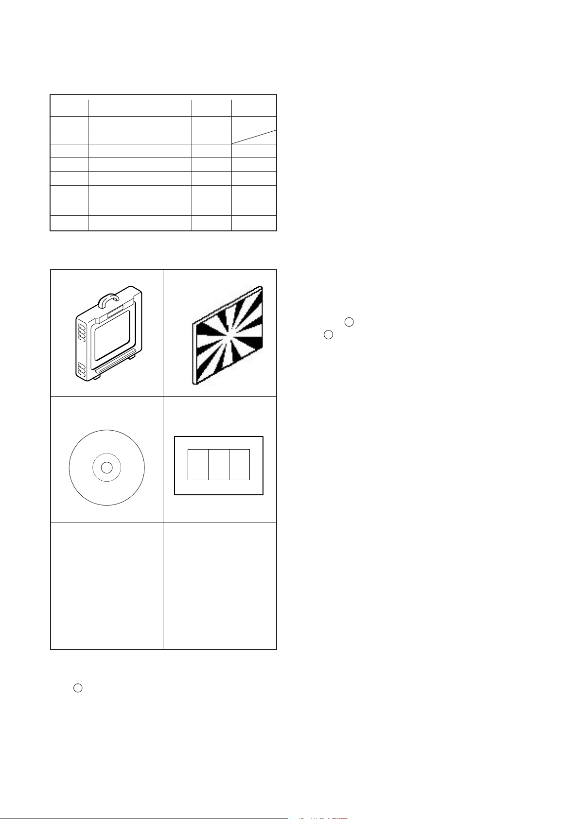
[1] Table for Servicing Tools
Ref. No.
J-1
Color viewer 5,100 K
J-2
Siemens star chart
J-3
Calibration software
Chart for color Adj.
J-4
J-5
Extention FPC D4106
µ DIGITAL ZOOM Adj. jig
J-6
Reflection prevention jig
Black curtain
Note: J-1 color viewer is 100 - 110 VAC only.
Name Part code
Number
1
1
1
1
1
1
1
1
J-1 J-2
J-3
J-4
VJ8-0007
KC0356
VJ8-0155
KC0355
KC0352
KC0320
KC0321
[3] Adjustment Items and Order
1. ZOOM Adjustment
2. CCD Block Adjustment
2-1. Mecashutter Adjustment
2-2. CCD Defect Adjustment
3. Color Adjustment
4. Focus Adjustment
5. VIDEO-OUT/LANGUAGE Write
Note:
1. You must make adjustment again when a lens, CCD,
each circuit board, others part are replaced. "Color adjustment" is to go after "the CCD block adjustment" and
"the focus adjustment".
[4] Setup
1. System requirements
WindowsR 98SE,2000
IBM R PC/AT-compatible PC with Pentium or higher pro-
cessor
CD-ROM drive
USB port
8 MB RAM
Hard disk drive with at least 15 MB available
VGA or SVGA monitor with at least 256-color display
[2] Equipment
1.IBM R PC/AT-compatible PC
2. USB Cable
3. AC adaptor
4. Thermometer
2. Installing calibration software
1. Insert the calibration software installation CD-ROM into
your CD-ROM drive.
2. Open Explorer.
3. Startup "Setup.exe" of the CD-ROM.
(Default installation pass : C:\DI\OL_Calib028_106)
4.Startup "OL_Calib028_106.exe".
C-2 Ver.1
Page 3
µ-10/µ [mju:] 300/Stylus 300 DIGITAL
µ-20/µ [mju:] 400/Stylus 400 DIGITAL
C. ADJUSTMENT METHOD
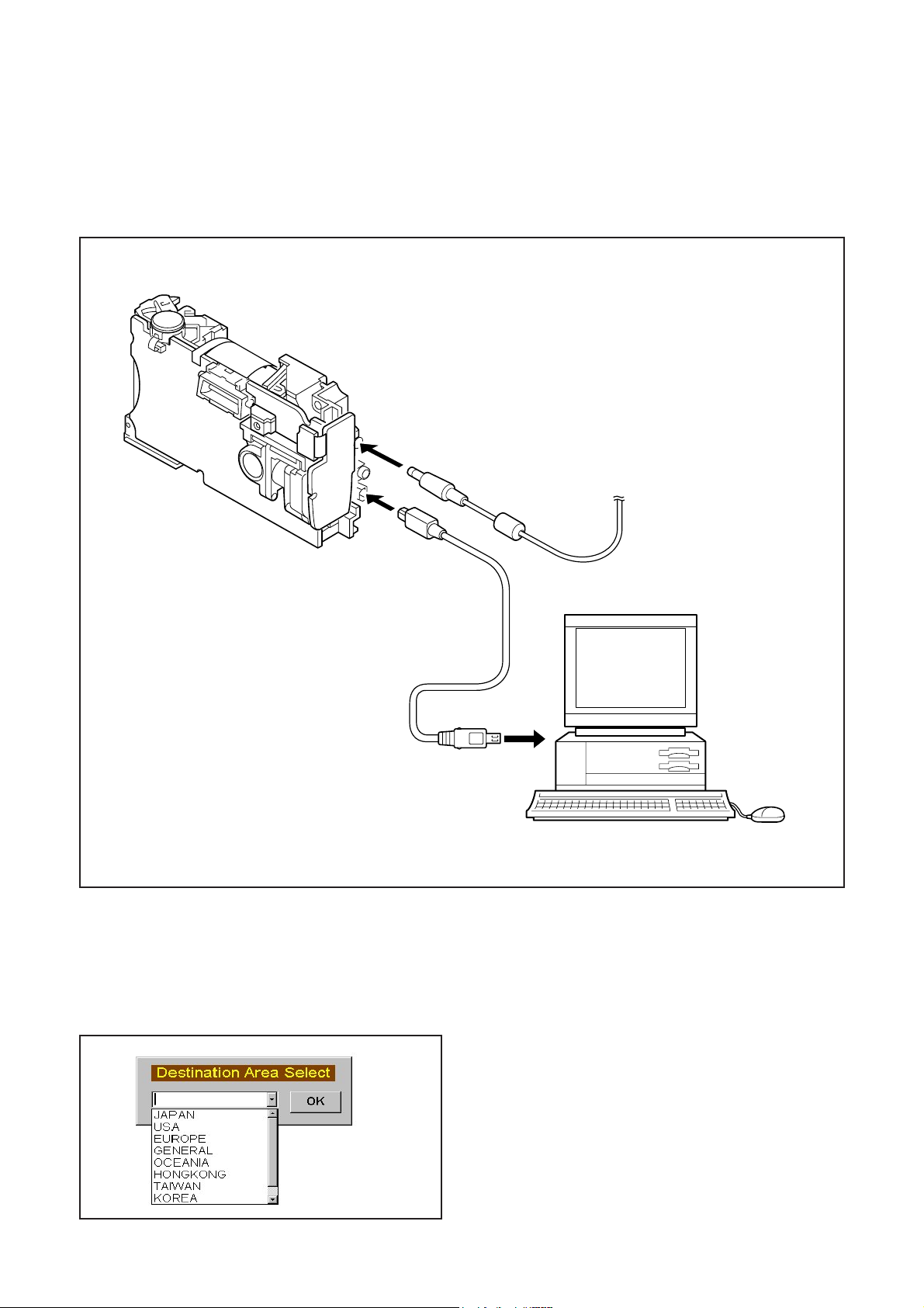
[5] Connecting the camera to the computer / Driver installation
1. An AC adapter is inserted in the camera, and a USB cable is inserted in the camera.
Note) A personal computer sometimes stops when a power supply is plugged in and out with a USB cable inserted in the
camera.
2. A driver is installed if it is recognized as a new hardware.
Default pass : C:\Di\OL_Calib028_106\USB Port Driver
AC adaptor
USB cable
To USB port
[6] Adjust Specifications
<Initialization(Only the first time of startup.)>
~ NTSC/PAL Language setup ~
Click your destination area
Note) Destination area can be selected at only first time of startup.
C-3Ver.1
Page 4

[6] Adjust Specifications
)
1. ZOOM Adjustment
ZOOM adj. for disassembled Lens unit
µ-10/µ [mju:] 300/Stylus 300 DIGITAL
C. ADJUSTMENT METHOD
2.ZOOM ADJUSTMENT
Preparation:
POWER switch: ON
Adjusting method:
<When Lens unit was disassembled>
Note: This adjustment should be adjusted without View Finder.
1. Connect K FPC to MC-PCA.
2. Connect Extension cable to CAM-PCA.
3. Connect the ather side of Extension cable to MC-PCA.
4. Set Lens unit to
5. Turn on the card cover swich. (Keep the switch position until finish.)
6. Click [2.ZOOM].
7. Click [ZOOM Adjustment] and [OK].
8. Confirm “OK”.
9. Fill
figures of K-FPC’s bar code. (The bar code data is invalidity.)
µ DIGITAL ZOOM Adjustment jig.
µ-20/µ [mju:] 400/Stylus 400 DIGITAL
Selection of adjustment mode
Inputting bar code data
2. CCD BLOCK Adjustment
USB cable
Camera
5 cm ±0.5 cm
Thermometer
All white pattern
Color viewer (5,100K
<When Lens unit was not disassembled>
1. Click [2.ZOOM].
2. Click [Input Bar Code Data] and [OK].
3. Input two figures of K-FPC’s bar code and click [OK].
4.Confirm “OK”.
Preparation:
Set the camera at 5cm (+/- 0.5cm) distance from color viewer.
POWER switch: ON
Condition:
The camera should be fixed in the position in which only white area of
Color Viewer is entered.
Do not enter any light except Color Viewer.
2-1. Mechanical shutter Adjustment
Adjusting method:
1.Click [3.MShutter].
2.Confirm “OK” .
2-2. CCD Defect Adjustment
Adjusting method:
1. Click [4.CCD Defect].
2. Input the circumference temperature of the camera and click [OK].
3. Confirm “OK” .
C-4 Ver.1
Page 5

µ-10/µ [mju:] 300/Stylus 300 DIGITAL
U
rt
U
µ-20/µ [mju:] 400/Stylus 400 DIGITAL
3. COLOR Adjustment
SB cable
Camera
17 cm ± 2 cm
All white pattern color
viewer (5,100K) and
color matrix adjustment cha
C. ADJUSTMENT METHOD
Preparation:
Set the camera at 17cm (+/- 2cm) distance from color viewer.
POWER switch: ON
Adjustment condition:
Do not enter any light except Color Viewer.
Adjustment method:
1. Click [5.CMatrix]
2. Click [LCD Monitor ON/OFF] to turn on the LCD monitor.
3. Set the color adjustment chart so that it is positioned at center of the LCD
monitor and click [LCD Monitor ON/OFF] to turn off the LCD monitor.
4. Click [EXIT] and the adjustment is started.
5. Confirm “OK” .
4. FOCUS Adjustment
SB cable
Camera
60 cm ±0.5 cm
5. VIDEO-OUT/LANGUAGE Write
Siemens
star chart
Preparation:
POWER switch: ON
Adjustment condition:
Siemens star chart (A3)
Fluorescent light illumination with no flicker
(incandescent light cannot be used.)
Illumination above the subject should be 400 lux ± 10%.
Set the siemens star chart 60 cm ± 0.5 cm so that it is positioned at
center of the LCD monitor.
Adjustment method:
1. Click [6.Focus].
2. Click [LCD Monitor ON/OFF] to turn on the LCD monitor.
3. Set the siemens star chart so that it is positioned at center of the
LCD monitor and click [LCD Monitor ON/OFF] to turn off the LCD monitor.
4. Click [EXIT] and the adjustment is started.
5. Confirm “OK” .
Preparation:
POWER switch: ON
Adjusting method:
1. Click [7.NTSC/PAL JPN/ENG Write].
2. Select Destination Area. (Japanese only)
3. Confirm “OK” .
C-5Ver.1
Page 6

6. OPTION
C. ADJUSTMENT METHOD
µ-10/µ [mju:] 300/Stylus 300 DIGITAL
µ-20/µ [mju:] 400/Stylus 400 DIGITAL
①Get Versions
②Search Device
⑤Adjus tment Data Save
⑦Switch Check ⑧DAMAGE Code
③US B OP EN
④US B C LOS E
⑥Adjustment Data Copy
(1)Get Versions
(The contents)
The firmware version
The serial number of MC-PCA
The body number
the pass flag of adjustment
(2)Search Device
(The device check)
“TRUE” : device detection
“FALSE”:undevice detection
(3)USB OPEN
“TRUE” : USB is connected
“FALSE”: USB communication error
(4) USB CLOSE
USB communication OFF
C-6 Ver.1
Page 7

µ-10/µ [mju:] 300/Stylus 300 DIGITAL
µ-20/µ [mju:] 400/Stylus 400 DIGITAL
(5)Adjustment Data Save
Location of save (default) :C: /DI /OL_Calib028_106/ Data Save/(camera serial number).csv
(6)Adjustment Data Copy
Save data from (default) C: /DI /OL_Calib028_106/ Data Save.
(Adjust “MShutter” after copying data)
(7)Switch check
Click “Start”.
The check signal is displayed on each check box when pressing each SW of Camera.
Press ESC key when finishing “Switch Check” .
(8)DAMAGE Code
Damage history is displayed.
Check the history with this function before adjustment so that the history is erase after adjustment.
C. ADJUSTMENT METHOD
(9)Camera Body No. write
The number of the camera is inputted, click “Write”.
[7] Adjustment Items
Adjus tment items
1. ZOOM Adjustment (Before setting Viewfinder)
1. ZOOM Adjustment (Input bar code data)
2-1. Mechanical shutter Adjustment
2-2. CCD Defect Adjustment
3. Color Adjustment
4. Focus Adjustment
5. VIDEO OUT/LANGUAGE Write - - - -
separate parts from Lens unit Lens unit CCD-ASSY LPF MC-PCA2
Changed repaire parts
C-7Ver.1
Page 8

CHECKING OF LENS UNIT
1. Check Item
1)Backlash Pulse of LD
2)LD ERROR Pulse
3)Basklash Pulse of ZOOM
4)ZOOM ERROR Pulse
2. Tools
C.ADJUSTMENT METHOD
µ-10/µ [mju:] 300/Stylus 300 DIGITAL
µ-20/µ [mju:] 400/Stylus 400 DIGITAL
FPC-Adaptor 21
PINS
Part No. Description Q'ty
1 KC0331 Lens Checker LCK1 1
2 KC0353 Connector CableP212 1
3 KC0332 Clip Connector 26 1
3 KC0354 Program RO M.v3 1
4 FPC-Adaptor 21PIN 1
(including KC0332)
Lens Checker LCK-1
The last 2 digits are mean-
ing the number of Pin.
080-10
3. Checking Procedure
Fi x FPC-Adaptors (21 PINS) to ClipConnector26.
Connect Connector Cable P212, Clip Connector
26 and Lens Checker LCK-1
1) AUTO
I. Tum on Lens Checker LCK-1
Initial Setting
II. Set AUTO / MANU SW at AUTO
III.Set Dial SW at 0
IV. Set CW / CCW SW at CW
LCK-1 Ver.3 0 Auto
PUSH START SW
Ex.) 080-10 :10PINS
Connector Cable P212
Clip Connector 26
(0 : Number of Dial SW 0-5)
V. Connect the K FPC to Clip Connectors.
Hold a lens unit by hand, and keep it horizontally.
VI. Push START SW. (More than 0.2 sec.)
LCK-1 Ver.3 0 Auto
ZOOM RESET
C-8 Ver.1
Page 9

µ-10/µ [mju:] 300/Stylus 300 DIGITAL
µ-20/µ [mju:] 400/Stylus 400 DIGITAL
C.ADJUSTMENT METHOD
When an error occurs, an error is indicated, and it stops.
LCK-1 Ver.3 0 Auto
ZOOM PR CHK
***
* is PR PULSE
LCK-1 Ver.3 0 Auto
ZOOM BACKLASH CHK
ZB *
* is BACKLASH PULSE
LCK-1 Ver.3 0 Auto
ZOOM HANI CHK
ZB ****
**** is OPERATION RANGE PULSE
LCK-1 Ver.3 0 Auto
LD BACKLASH CHK
LB* ZB
* is BACKLASH PULSE
In case of GOOD
LCK-1 Ver.3 0 Auto
PUSH START SW
LB1 D<
GOOD
In case of NG :
LCK-1 Ver.3 0 Auto
PUSH START SW
LB D<
NO GOOD ZM D Err
ERROR is indicated
(The indication which isn’t being explained is the condition
of PR and PI.)
When CW/CCW SW is set at CCW, the automatic check of
the motor chosen with a LD/ZOOM SW is done.
2) Manual
I. Set AUTO/MANU SW at MANU
LCK-1 Ver.3 0 Manu
LD CW
LCK-1 Ver.3 0 Auto
LD D CHK
LB1 D ** ZB
* * is SLIPPAGE PULSE (1st: Set up. 2nd: Set down.)
LCK-1 Ver.3 0 Auto
LD MUGEN CHK
LB1 D ** ZB ***
The contents chosen with the LD/ZOOM SW and the CW/
CCW SW indicated in LCD.
II. Push START SW (More than 0.2 sec.)
LCK-1 Ver.3 0 Manu
LD CW
MOVE
When a motor works, “MOVE” is indicated in LCD.
C-9Ver. 1
Page 10

C.ADJUSTMENT METHOD
LD Motor
When PI signal 500 pulses (500pps) are changed,LD motor
stops
CW : Turn Out CCW : Tum In
ZOOM Motor
When PI signal 2200 pulses (300pps) are changed, ZOOM
motor stops
CW : W to T CCW : T to W
4. Others
Turn off LCK-1 promptly if something is wrong.
5, ERROR Indication
PI, PR Err : PI or PR Pulse does not change.
LD BK Err : LD BACKLASH PULSE is out of standard.
LD D Err : LD Pulse Error
ZD BK Err : ZOOM BACKLASH PULSE is out of
standard
ZD D Err : ZOOM Pulse Error
µ-10/µ [mju:] 300/Stylus 300 DIGITAL
µ-20/µ [mju:] 400/Stylus 400 DIGITAL
C-10 Ver.1
 Loading...