

Page 1

MICROSCOPE
COMPONENTS GUIDE
Choosing The Ideal UIS2 Optics Components For Your Equipment
2006-11
Page 2

The wide range of Olympus components introduced here
allows users in such diverse fields as research, inspection and production
to take advantage of the quality, flexibility and
outstanding optical performance of the UIS2 Optical System.
That's why installing Olympus microscope components is,
quite simply, the right choice for your equipment.
1
Page 3

CONTENTS
2
EYEPIECES/FILAR MICROMETER EYEPIECE --------------------------------- 33
Widefield eyepieces WHN10x, WHN10x-H,
CROSSWHN10x, WH15x --------------------- 33
Super widefield eyepieces SWH10x-H, MICROSWH10x,
CROSSSWH10x ------------------------------ 33
Filar micrometer eyepiece U-OSM --------------------------------------- 33
REVOLVING NOSEPIECES---------------------------------------------------- 34 — 35
Quintuple revolving nosepiece U-5RE-2-------------------------------------- 34
Sextuple revolving nosepiece with slider slot for DIC
U-D6RE--------------------------------------- 34
Sextuple revolving nosepiece with slider slot for DIC with ESD treatment
U-D6RE-ESD --------------------------------- 34
Septuple revolving nosepiece with slider slot for DIC
U-D7RE -------------------------------------- 34
Centerable quadruple revolving nosepiece with slider slot for DIC
U-P4RE -------------------------------------- 34
Centerable sextuple revolving nosepiece with slider slot for DIC
U-P6RE -------------------------------------- 34
Quintuple revolving nosepiece for BF/DF
U-5BDRE ------------------------------------ 35
Quintuple revolving nosepiece for BF/DF with slider slot for DIC
U-D5BDRE ----------------------------------- 35
Sextuple revolving nosepiece for BF/DF with slider slot for DIC/
U-D6BDRE ----------------------------------- 35
Centerable quintuple revolving nosepiece
U-P5BDRE ----------------------------------- 35
Adapter to mount BF objectives
BD-M-AD ------------------------------------ 35
VIDEO CAMERA ADAPTERS ------------------------------------------------- 36 — 37
C-mount video camera ports U-TV0.25xC, U-TV0.35xC-2,
U-TV0.5xC-3, U-TV0.63xC ------------------- 36
Video camera mount adapters U-CMAD3, U-BMAD, U-SMAD,
U-TMAD, U-FMT ----------------------------- 37
Video camera port U-TV1x-2 ------------------------------------ 37
MOTORIZED UNITS------------------------------------------------------------- 38 — 41
Motorized BF/DF reflected light illuminator+motorized Nomarski DIC sextuple
revolving nosepiece+100W halogen lamp housing
BX-RLAA+U-D6REMC+U-LH100-3 ---------- 38
Motorized universal reflected light illuminator
BX-RFAA ------------------------------------- 38
Motorized quintuple BD revolving nosepiece with slider slot for DIC
U-D5BDREMC ------------------------------- 39
Motorized sextuple revolving nosepiece with slider slot for DIC
U-D6REMC ---------------------------------- 39
Motorized centerable quintuple revolving nosepiece with slider slot for DIC
U-P5REMC ----------------------------------- 39
Control unit BX-UCB -------------------------------------- 39
Hand switch U-HSTR2 ------------------------------------ 39
Control box for motorized nosepiece and BF/DF illuminator
BX-REMCB ---------------------------------- 39
AC adapter for BX-REMCB U-ACAD4515 -------------------------------- 39
Active auto focus unit U-AFA1M ------------------------------------ 40
Motorized reflected filter wheel U-FWR --------------------------------------- 40
Motorized illumination with power focus
BXFMA-F ------------------------------------ 41
DEEP ULTRAVIOLET OBSERVATION SYSTEM -------------------------------- 42
UV248 compatible intermediate tube
U-UVF248IM --------------------------------- 42
UV quartz light guide U-UVF2FV/5FB ------------------------------- 42
UV248 compatible light source box + Mercury Xenon lamp housing
U-UVF248LB+U-LH80HBXE ----------------- 42
OPTICAL TERMINOLOGY ---------------------------------------------------- 43 — 46
WELCOME TO UIS2/UIS OPTICS ---------------------------------------------- 3 — 4
SYSTEM DIAGRAM --------------------------------------------------------------- 5 — 6
UIS2/UIS OBJECTIVE LENSES ----------------------------------------------- 7 — 18
M Plan SemiApochromat MPLFLN series -------------------------------- 8
Long WD M Plan SemiApochromat LMPLFLN series ------------------------------ 9
M Plan Achromat MPLN series --------------------------------- 10
LCD Long WD M Plan SemiApochromat
LCPLFLN-LCD series -------------------------11
M Plan Apochromat MPlanApo series -----------------------------12
Super Long WD M Plan Achromat SLMPlan series -------------------------------12
IR Long WD M Plan SemiApochromat
LMPlan-IR series -----------------------------13
IR M Plan SemiApochromat MPlan-IR -------------------------------------13
M Plan SemiApochromat BD MPLFLN-BD series ---------------------------14
M Plan SemiApochromat BDP MPLFLN-BDP series --------------------------15
Long WD M Plan SemiApochromat BD
LMPLFLN-BD series --------------------------16
M Plan Achromat BD MPLN-BD series ------------------------------17
M Plan Apochromat BD MPlanApo-BD --------------------------------18
MICROSCOPE SYSTEM BXFM ---------------------------------------------- 19 — 22
BXFM frame BXFM-F -------------------------------------- 19
BXFM BXFM-F+BXFM-ILH+BXFM-ILHSPU---------- 20
BXFM-S BXFM-F+BXFM-ILHS ------------------------ 21
Universal stand type 2 SZ2-STU2 ----------------------------------- 22
Compact stand U-ST ----------------------------------------- 22
Large stand SZ-STL -------------------------------------- 22
ILLUMINATION UNITS --------------------------------------------------------- 23 — 25
Reflected light illuminator for BF/DF
BX-RLA2 ------------------------------------- 23
Universal reflected light illuminatorBX-URA2 ------------------------------------ 23
Reflected light illuminators for BF BX-KMA/BX-KMA-ESD ----------------------- 24
Reflected light illuminator for BF U-KMAS ------------------------------------- 25
LAMP HOUSING & ACCESSORIES ----------------------------------------- 26 — 28
75W xenon apo lamp housing U-LH75XEAPO------------------------------- 26
100W mercury apo lamp housing U-LH100HGAPO ----------------------------- 26
100W mercury lamp housing U-LH100HG ---------------------------------- 26
100W halogen lamp housings U-LH100-3/U-LH100IR/U-LH100L-3 -------- 26
External power supply TH4-100/200 -------------------------------- 27
Hand switch TH4-HS -------------------------------------- 27
Extension cord U-RMT --------------------------------------- 27
DF converter for BX-URA2 U-RCV --------------------------------------- 27
Fiber adapter for reflected light observation
U-LGAD -------------------------------------- 27
Transmitted light guide adapter SZX-TLGAD ---------------------------------- 27
Light source LG-PS2 -------------------------------------- 28
Light guide LG-SF ---------------------------------------- 28
Double lamp house adapter U-DULHA ------------------------------------ 28
OBSERVATION TUBES -------------------------------------------------------- 29 — 30
Widefield binocular tube U-TR30-2 ------------------------------------ 29
Widefield binocular tube for IR U-TR30IR ------------------------------------ 29
Widefield erect image trinocular tube
U-ETR-4 ------------------------------------- 29
Single port tube with lens U-TLU ---------------------------------------- 29
Single port tube with lens for IR U-TLUIR ------------------------------------- 29
Super widefield trinocular tube U-SWTR-3 ----------------------------------- 30
Super widefield erect image trinocular tube
U-SWETR ------------------------------------ 30
Super widefield erect image tilting trinocular tube
MX-SWETTR --------------------------------- 30
INTERMEDIATE TUBES & ACCESSORIES ------------------------------- 31 — 32
Magnification changer U-CA ----------------------------------------- 31
Magnification changer 2x U-ECA --------------------------------------- 31
Trinocular intermediate attachment
U-TRU --------------------------------------- 31
Dual port U-DP ----------------------------------------- 32
Dual port 1x U-DP1xC ------------------------------------- 32
Eyepoint adjuster U-EPA2 -------------------------------------- 32
Arrow pointer U-APT --------------------------------------- 32
Page 4

light between the objective lens and tube lens,
allowing the creation of user-specific or taskspecific optical systems. To establish real flexibility
with such a system, it is necessary to eliminate the
occurrence of coma aberration.
*In UIS2/UIS objective lenses, the parfocal distance is designed
at 45mm and the focal length of the tube lens is 180mm.
Basic dimensions of UIS2/UIS optical system
The UIS2/UIS optical system optimally corrects
aberration with a dedicated telan lens and an
eyepiece so that the coma aberration and flatness
are not degraded even when the telan lens exit
pupil position is changed by changing the
objective lens and telan distance. This makes it
possible to use a distance of 50mm to 170mm
from objective lens mounting position to the single
port tube with lens.
*Coma aberration: refer to the optical terminology at the end of
this document.
What's infinity-corrected optics?
UIS2/UIS optics is an infinity-corrected optical
system — in other words, a system in which light
passes from the specimen through the objective
lens without forming an image along the way.
Instead, it travels in the form of infinity parallel rays
to the tube lens. The tube lens is where the
intermediate image is formed, whereas in finitecorrected optics, this is done by the objective lens.
Advantages of infinity-corrected optics
This system, known as "infinity-corrected optics",
offers a number of advantages:
• There is no change in magnification even when
the distance between the objective lens and tube
lens is altered.
• With the total magnification remaining constant,
there is no image aberration — even when
prisms or sliders are interposed between the
objective lens and the tube lens.
As thousands of users have found by experience,
these advantages are crucial to composing the
ideal microscope optical system. What's more, it
is even possible to freely insert or remove
intermediate attachments in the parallel rays of
Figure 1 Infinity-corrected and
finite-corrected optical system principles
Infinity-corrected optical system
Finite-corrected optical system
Parallel light beam
Eyepiece
Eyepiece
UIS/UIS2
objective lens
Objective
lens
Tube lens Intermediate
image
Intermediate
image
3
WELCOME TO UIS2/UIS OPTICS
UIS2/UIS:
The System That Maximizes The Advantage Of Infinity-Corrected Optics
Figure 3 Basic dimensions of UIS2/UIS2
optical system
Objective lens
U-TLU
(Single port tube with lens)
Image
Recommended distance
50-170mm
* 40mm
45mm
* 84mm
57.6mm 102mm
*Basic dimensions when our revolving nosepiece and illuminator are
combined. When the position of the illuminator above is changed,
illumination performance cannot be maintained.
Figure 2 Advantages of Infinity-corrected
optical system
Infinity-corrected optical system Finite-corrected optical system
Objective
lens
Tube lens
Objective
lens
Page 5

4. Lightening
Weight has been reduced to approximately 2/3
that of conventional products by using an
aluminum objective lens barrel cover. This has
the effect of lightening the load on the devices at
objective lens up/down, suppressing vibrations
by lowering the inertial force at objective lens
switching, etc. (MPLFLN series, LMPLFLN
series)
5. Adoption of eco-lens
The glass materials of UIS2 objective lenses are
all lead- and cadmium-free eco-glass.
Features of UIS2 objective lenses
UIS2 objective lenses ensure compatibility (screw
diameter, optical performance) with the UIS optical
system and have the following features compared
to conventional objective lenses.
1. Wavefront aberration control
The Olympus UIS2 objective lenses set a new
standard, with wavefront aberration control in
addition to common performance standards of
N.A. and W.D. Olympus challenges farther
highest order optics which has not been fulfilled
by the conventional standards. We offer
excellent performance objective lenses by
minimizing the aberrations that lower resolution.
*Wave front aberration: refer to the optical terminology at the
end of this document.
2. Objective lenses with excellent image
parcentricity
High power SemiApochromatic UIS2 objective
lenses make the centration tolerance between
objective lenses on the microscope nosepiece
keep the image within the enter of the field of
view even with digital cameras. (50x or higher
power in both MPLFLN and LMPLFLN series)
3. Improvement of color reproducibility
UIS2 objective lenses realize natural color
reproduction without any chromatic shifts using
stringently selected high transmittance glass
and advanced coating technology that provides
high transmittance which is flat over an ultrawide band wavelength. In addition, since the
total optical system, including the tube lens is
designed to reproduce a natural color, clear
images faithful to the specimen are obtained
even with digital imaging.
WELCOME TO UIS2/UIS OPTICS
4
Based on our conviction that the UIS2/UIS
system is the best way to maximize the
advantages of infinity-corrected optical
systems, we confidently recommend the
UIS2/UIS-featured Olympus microscope units
for all your high-precision needs in research,
inspection and production equipment.
* Refer to the Olympus home page for detailed
objective lenses specifications.
Page 6
5
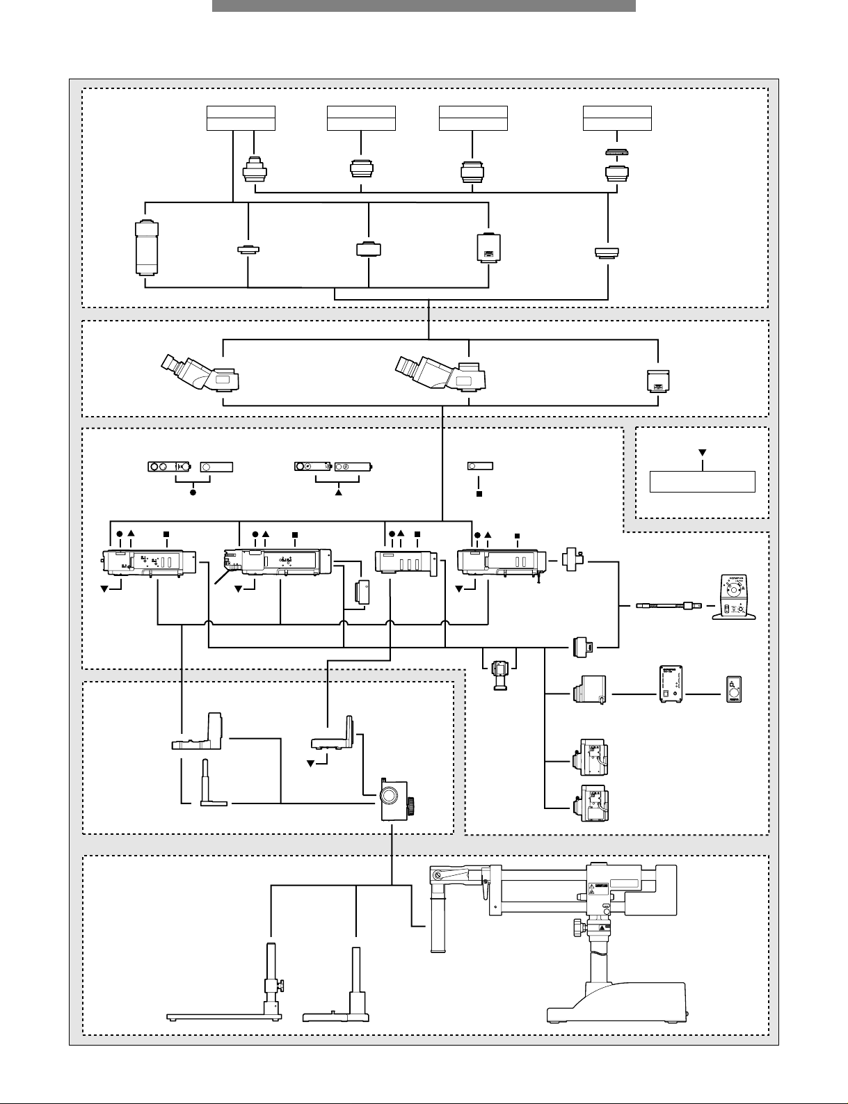
SYSTEM DIAGRAM
5
6
SHUTTERSHUTTER
5
6
SHUTTER
U-AN
U-AN360-3
U-AN360IR
LG-SF
LG-PS2
U-LH100HGAPO
U-LH100HG
U-LH75XEAPO
U-LH100-3
U-LH100L-3
U-LH100IR
Super widefield trinocular
observation tubes
Widefield trinocular
observation tubes
U-TLU
U-TLUIR
U-25ND6, U-25ND25,
U-25LBD, U-25IF550,
U-25L42, U-25FR,
U-BP1100IR, U-BP1200IR
U-PO3
U-POIR
SZ2-STU2
U-LGAD
TH4-100 TH4-HS
U-STSZ-STL
BXFM-ILH
BXFM-ILHS
BXFM-F
BXFM-ILHSPU
WHN
Eyepieces
SWH
Eyepieces
BX-RLA2
ND
FS
AS
BX-URA2
U-RCV
U-KMAS
SZX-TLGAD
U-DULHA
BX-KMA/
BX-KMA-ESD
U-POTP3
FS
AS
U-TV0.25xC U-TV0.35xC-2 U-TV0.5xC-3 U-TV0.63xC
U-TMAD
U-BMAD U-SMAD
U-FMT
U-CMAD3
Video camera
C-mount
Video camera
S mount 2/3"
Video camera
F mount
Video camera
B mount 2/3"
U-TV1x-2
Revolving nosepiece
(Refer to pages 34-35)
Refer to pages 19-21
Refer to page 22
Refer to pages 23-28
Refer to pages 29-30
Illumination systems and power supply
Focusing units
Stands
Refer to pages 36-37
Video system
Observation/single tubes
and eyepieces
BXFM SYSTEM DIAGRAM
*Different types may be offered in each area.
Page 7
6
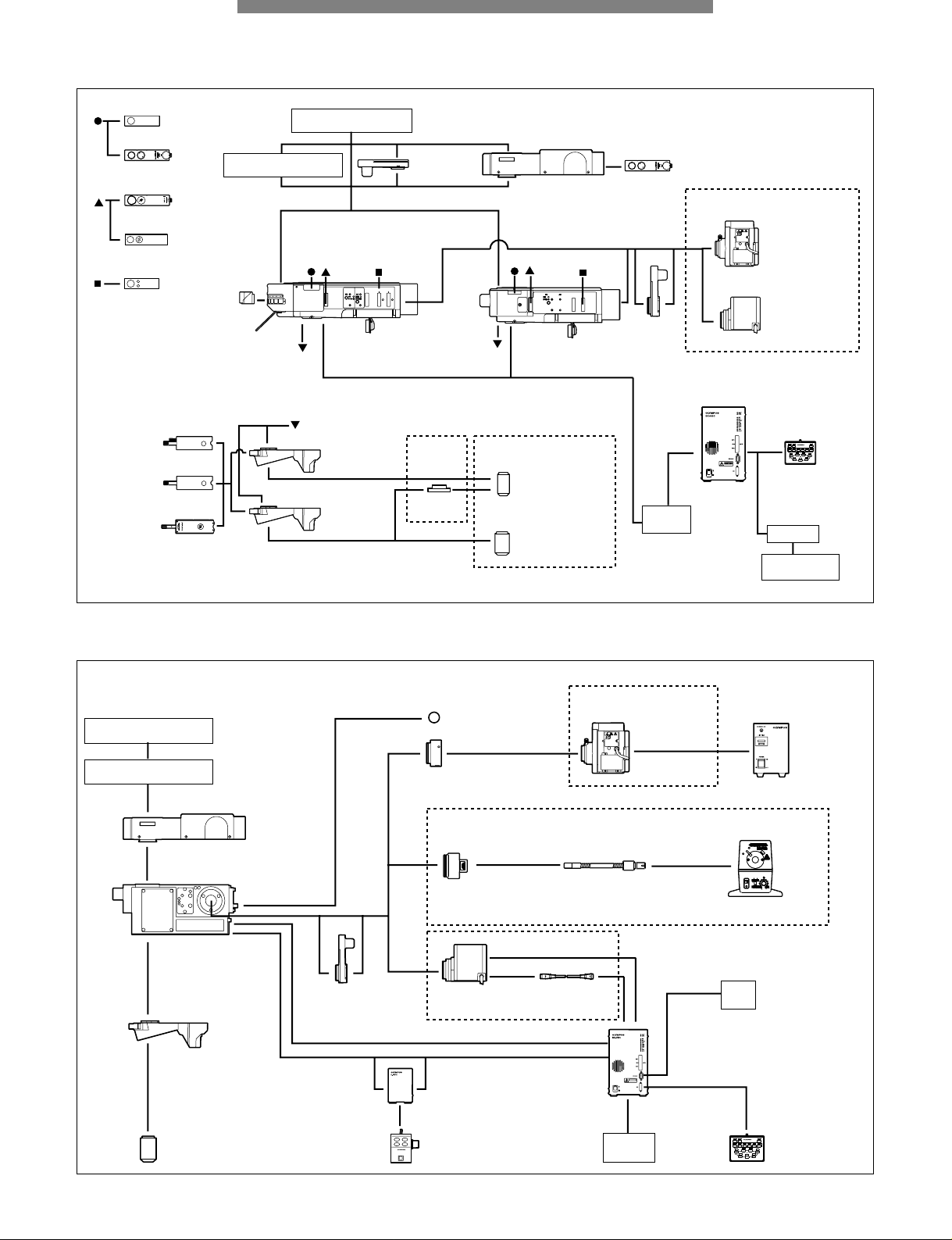
SYSTEM DIAGRAM
MOTORIZED UNIT SYSTEM DIAGRAM
BXFM-A SYSTEM DIAGRAM
See manual
U-D5BDREMC
U-D6REMC
U-FWO
BX-RFAA
U-AN360RAF
U-AFA1M
BX-RLAA
U-LH100-3
U-LH100L-3
U-FWR
Intermediate tubes
(Refer to pages 31-32)
Observation tubes
(Refer to pages 29-30)
U-DICRHC
U-DICR
U-DICRH
U-AN360-3
U-25ND6,
U-25ND25
U-25LBD
U-25IF550
U-25L42
U-25FR
U-PO3
U-AN
U-HSTR2
BX-UCB*
U-ZPCB
Z board
U-POTP3
PC
BX2BSW
Control software
Mirror units
U-LH75XEAPO
U-LH100HGAPO
U-LH100HG
BF/DF objective lenses
BF objective lenses
BD-M-AD
Refer to pages 38-40
Refer to page 26
Refer to pages 7-18Refer to
page 35
* BX-REMCB is also available for BX-RLAA + motorized revolving nosepiece control (refer to page 39)
Video system
(Refer to pages 37-38)
Observation tubes
(Refer to pages 29-30)
U-AFA1M
BXFMA-F
U-D6REMC
U-P5REMC
U-D5BDREMC
Objective lenses
U-FWR
ø32filter
Auxiliary lens
(provided with the BXFMA-F)
U-LGAD
Refer to pages 26-27
U-LH100-3
U-LH100L-3
U-IFFH
U-FH
U-RMT
LG-SF
Refer to page 26
U-LH100HG
U-LH75XEAPO
See manual
BX-UCB
U-ZPCB
Z board
Refer to pages 27-28
PC
Refer to page 41
Power source
LG-PS2
U-HSTR2
Page 8
7
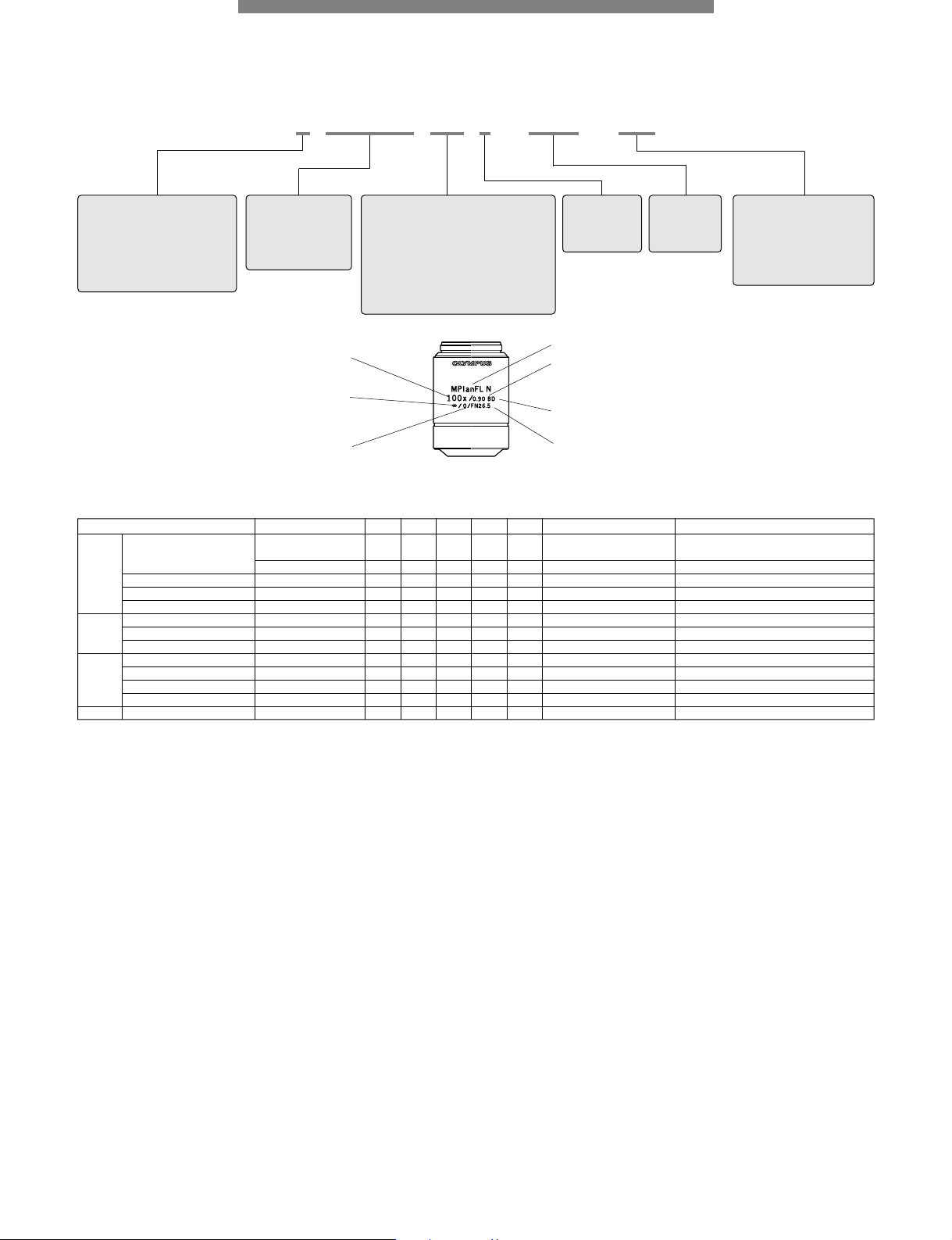
UIS2/UIS OBJECTIVE LENSES
MPL(Plan)
FLN-100 BD
■ Objective lens series list
■ Meaning of abbreviations shown on objective lens
■ Objective lens notation
■ Features of objective lens series
None: Brightfield
BD: Brightfield/darkfield
BDP: Brightfield/darkfield/
polarizing
IR: IR
LCD: LCD
None:
UIS
N: UIS2
Number:
Objective lens
magnification
Series Magnification BF DF DIC*1POL FL F.N. (Field Number) Remarks
UIS2 MPLFLN 1.25/2.5 \ 1.25x: 22 / 2.5x: 26.5 Use together with polarizer and analyzer
recommended
5/10/20/50/100 \\U \\
*2
26.5
LMPLFLN 5/10/20/50/100 \\L \\ 26.5
MPLN 5/10/20/50/100 \ 22
LCPLFLN-LCD 20/50/100 \\L 26.5 For LCD
UIS MPlanApo 20/50/100 \\
*3
U \ 26.5
SLMPlan 20/50 \ 26.5
LMPlanIR/MPlanIR 5/10/20/50/100 *
4
\ 22 For near-IR observation
UIS2 MPLFLN-BD 5/10/20/50/100/150 \\\U \\
*2
26.5
MPLFLN-BDP 5/10/20/50/100 \\aU a\
*2
26.5
LMPLFLN-BD 5/10/20/50/100 \\\L \\ 26.5
MPLN-BD 5/10/20/50/100 \\ 22
UIS MPlanApo-BD 100 \\\U \ 26.5
*
1
DIC prism U-DICR: UM/LM position, U-DICRHC: LM position fixed, U-DICRH: UM position fixed. *25~20x: U excitation also possible
*
3
50x: DIC observation not applicable *4MPlanIR: available 100x only \: Responds a: Optimally responds BF: Brightfield DF: Darkfield
DIC: Differential Interference Contrast POL: Polarized light FL: Fluorescence
M: Metallurgical (no cover)
LM: Long working distance
metallurgical use
SLM: Super long working
distance metallurgical use
LC: Observation through
substrate
None: Achromat/
Corrects aberration at 2 wavelengths of
blue and red
FL: SemiApochromat/
Corrects chromatic aberration in the
visible range (violet~red)
APO: Apochromat/
Optimally corrects chromatic aberration
in the entire visible band (violet~red)
PL: Plan/
Corrects field
curvature of
the periphery of
the image plane
Magnification
Objective lenses series abbreviation (PL: Plan)
N.A. (Numerical Aperture)
Field Number
For brightfield observation
Infinity-corrected optical system
Cover glass thickness (no cover)
a MPLFLN series: M Plan SemiApochromat — P 8
Plan SemiApochromat objective lenses, giving high-level correction for chromatic aberration.
The lineup consists of 7 objective lenses ranging from 1.25x to 100x, and secures a W.D. of
1mm or longer. Since the exit pupil position of the 5x-100x objective lenses is standardized,
the position of the DIC prism does not have to be switched when changing the magnification.
For ultra low magnifications (1.25x, 2.5x), use together with analyzer and polarizer of the
reflected light illuminator.
a LMPLFLN series: Long WD M Plan SemiApochromat — P 9
Long working distance Plan SemiApochromat objective lenses, giving high-level correction
for chromatic aberration. Suitable with samples having a height difference and in preventing
collision, as the working distance is long. Also, since the exit pupil position of the 5x-100x
objective lenses is standardized, the position of the DIC prism does not have to be switched
when changing the magnification.
a MPLN series: M Plan Achromat — P 10
Plan Achromat objective lenses providing excellent image flatness up to F.N. 22.
a LCPLFLN-LCD series: LCD Long WD M Plan SemiApochromat — P 11
Perfect objective lens series for observation of LCD panels and other samples through a
glass substrate. Aberration correction matched to the glass thickness is accomplished using
a correction ring.
a MPlanApo series: M Plan Apochromat — P 12
Highest class Plan Apochromat objective lenses that maximize performance in brightfield
observation. All aberrations are corrected at the highest level, while providing high N.A.
a SLMPlan series: Super Long WD M Plan Achromat — P 12
Plan Achromat objective lenses with high magnification and super long working distance.
Two magnifications, 20x and 50x are available. For 5x or 10x objective lenses, select from
the LMPLFLN Series.
a LMPlan-IR series: IR Long WD M Plan SemiApochromat — P 13
MPlan-IR: IR M Plan SemiApochromat — P 13
IR objective lenses which compensate for aberrations from visible to near infrared light.
Ideal for the observations of semiconductor interiors and the back surface of a chip package
as well as CSP bump inspection.
a MPLFLN-BD series: M Plan SemiApochromat BD — P 14
Plan SemiApochromat objective lenses, giving high-level correction for chromatic aberration.
The series secures a W.D. of 1mm or longer. Since the exit pupil position of the 5x-150x
objective lenses is standardized, the position of the DIC prism does not have to be switched
when changing the magnification.
a MPLFLN-BDP series: M Plan SemiApochromat BDP — P 15
Plan SemiApochromat objective lenses, giving high-level correction for chromatic aberration.
The series secures a W.D. of 1mm or longer. Since the exit pupil position of the 5x-100x
objective lenses is standardized, the position of the DIC prism does not have to be switched
when changing the magnification. The BDP series optimizing brightfield/darkfield and
polarized light characteristics is perfect for Nomarski DIC and polarized light observations.
a LMPLFLN-BD series: Long WD M Plan SemiApochromat BD — P 16
Long working distance Plan SemiApochromat objective lenses, giving high-level correction
for chromatic aberration. Suitable with samples having a height difference and in preventing
collision, as the working distance is long. Also, since the exit pupil position of the 5x-100x
objective lenses is standardized, the position of the DIC prism does not have to be switched
when changing the magnification.
a MPLN-BD series: M Plan Achromat BD — P 17
Plan Achromat objective lenses providing excellent image flatness up to F.N. 22.
a MPlanApo BD: Plan Apochromat BD — P 18
Highest class Plan Apochromat objective lens that maximize performance in brightfield and
darkfield observations. All aberrations are corrected at the highest level, while providing
high N.A.
Page 9
UIS2 OBJECTIVE LENSES
8
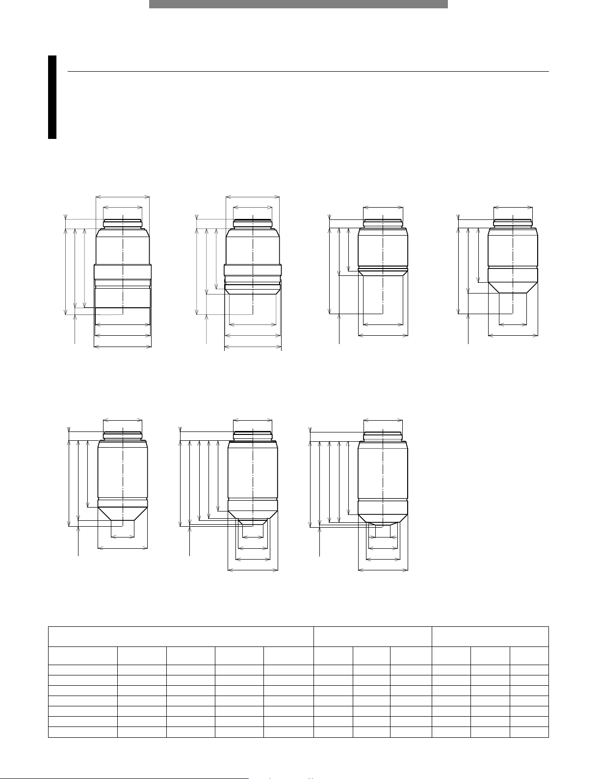
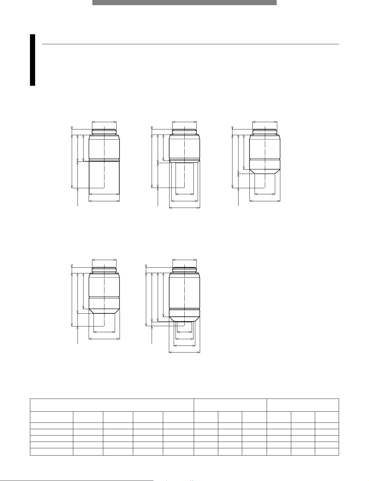
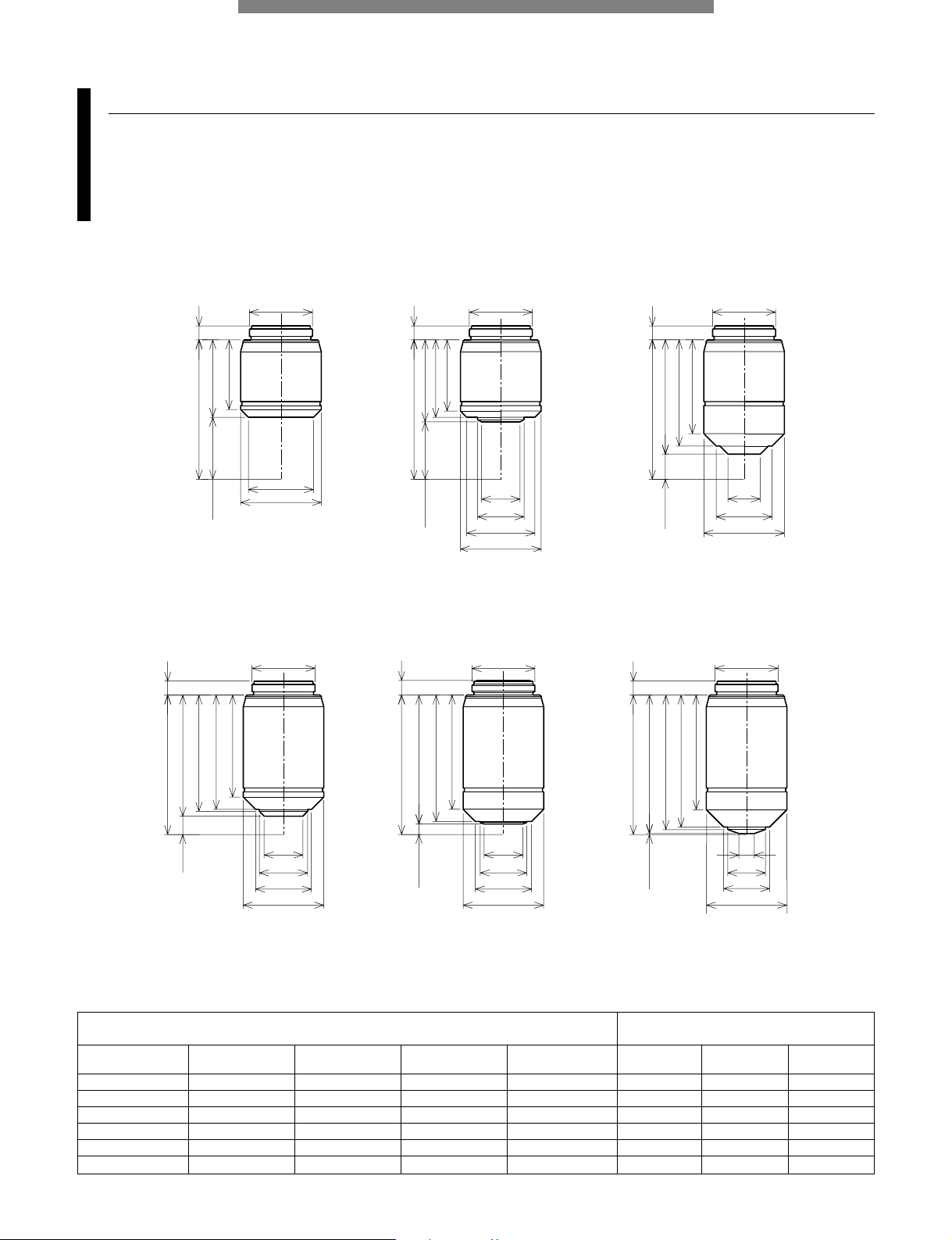
M Plan SemiApochromat
MPLFLN series
Plan SemiApochromat objective lenses, giving high-level correction for chromatic aberration. The lineup consists of 7 objective
lenses ranging from 1.25x to 100x, and secures a W.D. of 1mm or longer. Since the exit pupil position of the 5x-100x objective
lenses is standardized, the position of the DIC prism does not have to be switched when changing the magnification.
For ultra low magnifications (1.25x, 2.5x), use together with analyzer and polarizer of the reflected light illuminator.
ø28
ø20.32
ø28
ø20.32
ø20.32
ø20.32
ø30
ø29
ø28.6
ø30
ø29
ø24.5
ø26
ø20.9
ø26
ø14.5
4.9
WD=3.5
45
(41.5)
41.2
45
4.9
(34.3)
WD=10.7
31.6
45
4.5
WD=20
WD=11
(25)
22.55
(34)
4.5
45
28.41
ø20.32
ø20.32 ø20.32
ø10.7
ø15.2
ø17.8
ø26
ø7.8
ø15.2
ø17.8
ø26
ø26
ø12.1
WD=3.1
4.5
(41.9)
45
35.1
WD=1
45
4.8
(44)
38.4
42.4
42.61
4.8
45
WD=1
(44)
41.78
40.8
36.8
MPLFLN1.25x* MPLFLN2.5x* MPLFLN5x MPLFLN10x
MPLFLN20x MPLFLN50x MPLFLN100x
MPLFLN 1.25x* 0.04 3.5 145 122 12.5 17.6 870 —— —
MPLFLN 2.5x* 0.08 10.7 72 106 25 8.8 220 25 10.6 220
MPLFLN 5x 0.15 20.0 36 51.5 50 4.4 59 50 5.3 59
MPLFLN 10x 0.30 11.0 18 68.1 100 2.2 15 100 2.7 15
MPLFLN 20x 0.45 3.1 9 70.4 200 1.1 5.2 200 1.3 5.1
MPLFLN 50x 0.80 1.0 3.6 89.9 500 0.44 1.3 500 0.53 1.3
MPLFLN 100x 0.90 1.0 1.8 90.9 1000 0.22 0.73 1000 0.27 0.73
Numerical
Aperture
Working distance
(mm)
Focal distance
f (mm)
Weight
(g)
Total
magnifications
Practical field
of view (mm)
Depth of
focus (µm)
Total
magnifications
Practical field
of view (mm)
Depth of
focus (µm)
UIS2 objective lenses
Widefield eyepiece WHN10x
Field Number 22
Super widefield eyepiece SWH10x
Field Number 26.5
Objective lens
(magnification)
Screw: W20.32x0.706 (0.8"x1/36") * To be available in the beginning of 2007
Unit: mm
Page 10
UIS2 OBJECTIVE LENSES
9
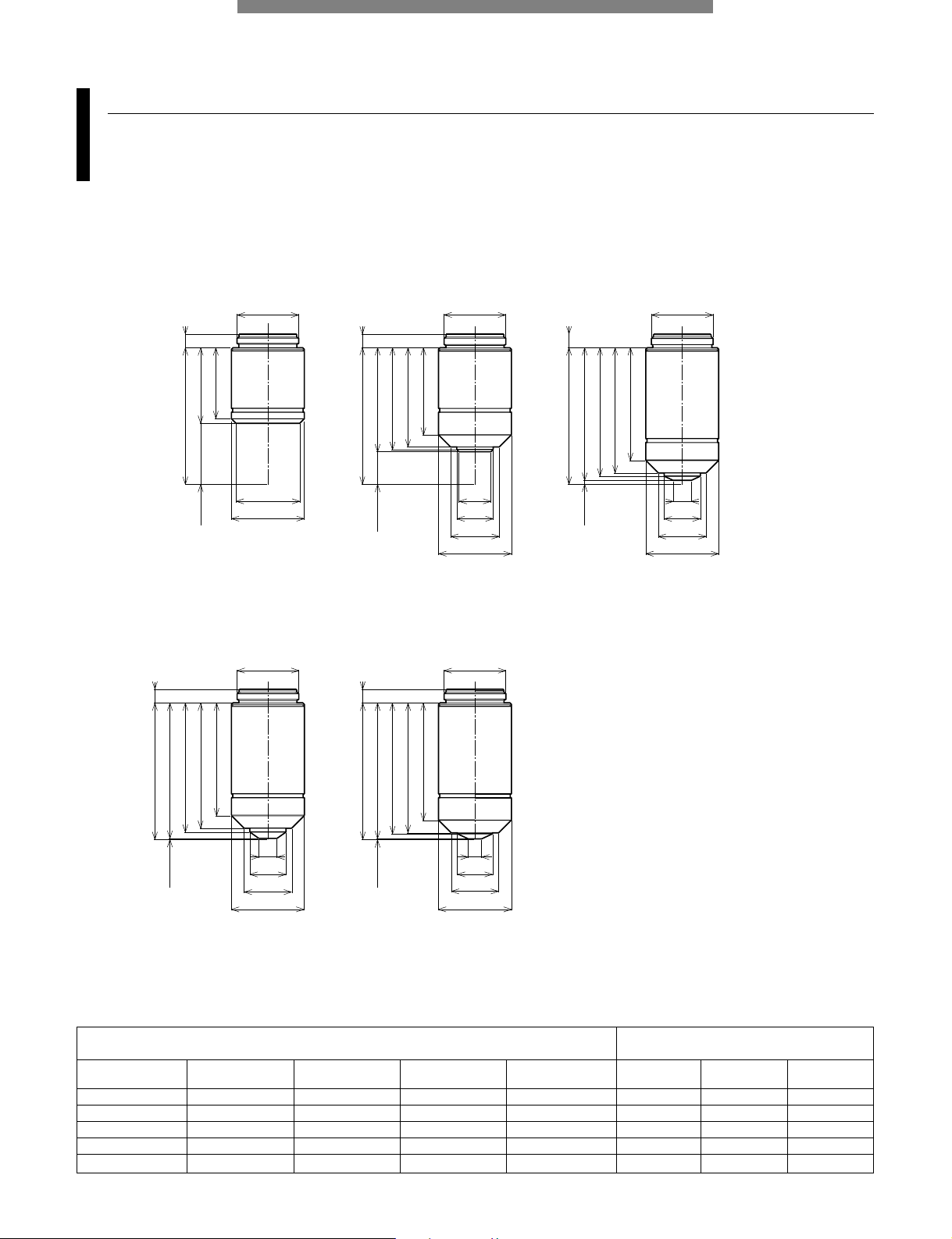
Long WD M Plan SemiApochromat (WD: Working Distance)
LMPLFLN series
Long working distance Plan SemiApochromat objective lenses, giving high-level correction for chromatic aberration.
Suitable with samples having a height difference and in preventing collision, as the working distance is long.
Also, since the exit pupil position of the 5x-100x objective lenses is standardized, the position of the DIC prism does not have
to be switched when changing the magnification.
LMPLFLN 5x 0.13 22.5 36 50 50 4.4 70 50 5.3 70
LMPLFLN 10x 0.25 21.0 18 54 100 2.2 18 100 2.7 18
LMPLFLN 20x 0.40 12.0 9 73 200 1.1 6.1 200 1.3 6.1
LMPLFLN 50x 0.50 10.6 3.6 77 500 0.44 2.5 500 0.53 2.5
LMPLFLN 100x 0.80 3.4 1.8 94 1000 0.22 0.87 1000 0.27 0.87
Numerical
Aperture
Working distance
(mm)
Weight
(g)
Focal distance
f (mm)
Total
magnifications
Practical field
of view (mm)
Depth of
focus (µm)
Total
magnifications
Practical field
of view (mm)
Depth of
focus (µm)
UIS2 objective lenses
Widefield eyepiece WHN10x
Field Number 22
Super widefield eyepiece SWH10x
Field Number 26.5
Objective lens
(magnification)
Screw: W20.32x0.706 (0.8"x1/36")
Unit: mm
45
4.5
WD=21
(24)
ø22.4
ø26
ø26
ø17
ø26
22.1
ø15.2
45
WD=22.5
4.9
(22.5)
ø25.4
22.2
4.8
(33)WD=12
45
29.31
ø20.32ø20.32ø20.32
ø26
ø18.2
WD=3.4 (41.6)
45
4.7
ø20.32ø20.32
ø12.5
ø15
ø18.1
41.1
37.26
ø26
45
WD=10.6
(34.4)
4.9
30.4
LMPLFLN5x LMPLFLN10x LMPLFLN20x
LMPLFLN50x LMPLFLN100x
Page 11
10
UIS2 OBJECTIVE LENSES
Unit: mm
M Plan Achromat
MPLN series
Plan Achromat objective lenses providing excellent image flatness up to F.N. 22.
MPLN 5x 0.10 20.0 36 64 50 4.4 98
MPLN 10x 0.25 10.6 18 80 100 2.2 18
MPLN 20x 0.40 1.3 9 111 200 1.1 6.1
MPLN 50x 0.75 0.38 3.6 113 500 0.44 1.4
MPLN 100x 0.90 0.21 1.8 116 1000 0.22 0.73
Numerical
Aperture
Working distance
(mm)
Focal distance
f (mm)
Weight
(g)
Total
magnifications
Practical field of
view (mm)
Depth of focus
(µm)
UIS2 objective lenses
Widefield eyepiece WHN10x
Field Number 22
Objective lens
(magnification)
Screw: W20.32x0.706 (0.8"x1/36")
ø20.32
ø20.32
ø20.32
ø6
ø11.9
ø15.8
ø24
ø21
ø24
ø24
ø16
ø12
ø10.5
45 4.5
23.4
(25)
WD=20
WD=10.6 (34.4)
4.545
32.71
28.8
33.6
4.5
(43.7)
45
WD=1.3
37.2
41.3
42.4
ø20.32
ø20.32
ø6
ø11.9
ø15.8
ø24
ø4.4
ø11.6
ø15.6
ø24
(44.62)WD=0.38
4.5
45
37.2
41.3
42.62
WD=0.21 (44.79)
45
4.5
38.7
42.8
43.16
MPLN5x MPLN10x MPLN20x
MPLN50x MPLN100x
Page 12
UIS2 OBJECTIVE LENSES
11
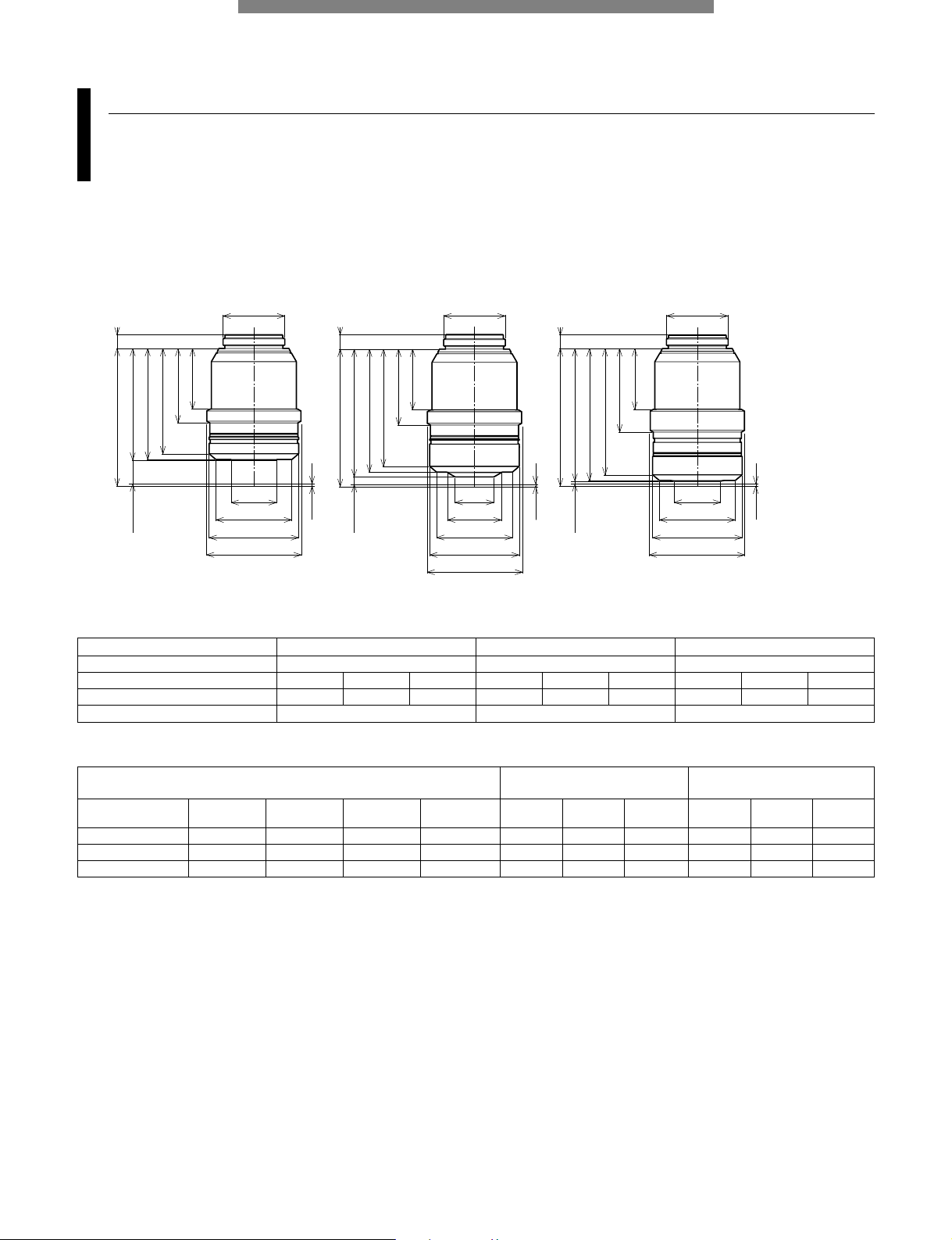
LCD Long WD M Plan SemiApochromat
LCPLFLN-LCD series
Perfect objective lens series for observation of LCD panels and other samples through a glass substrate.
Aberration correction matched to the glass thickness is accomplished using a correction ring.
Objective lens LCPLFLN20xLCD LCPLFLN50xLCD LCPLFLN100xLCD
Corresponding glass thickness (mm) 0-1.2 0-1.2 0-0.7
Correction ring indication 0 0.7 1.2 0 0.7 1.2 0 0.5 0.7
Working distance (mm) 8.3 7.8 7.4 3.0 2.5 2.2 1.2 0.98 0.9
Correction system Correction ring Correction ring Correction ring
LCPLFLN20xLCD*** 0.45 7.8 9 146 200 1.1 5.2 200 1.3 5.2
LCPLFLN50xLCD*** 0.70 2.5 3.6 170 500 0.44 1.6 500 0.53 1.6
LCPLFLN100xLCD*** 0.85 0.9 1.8 185 1000 0.22 0.79 1000 0.27 0.79
Numerical
Aperture
Working distance**
(mm)
Focal distance
f (mm)
Weight
(g)
Total
magnifications
Practical field
of view (mm)
Depth of
focus (µm)
Total
magnifications
Practical field
of view (mm)
Depth of
focus (µm)
UIS2 objective lenses
Widefield eyepiece WHN10x
Field Number 22
Super widefield eyepiece SWH10x
Field Number 26.5
Objective lens
(magnification)
Screw: W20.32x0.706 (0.8"x1/36") **The figure shown here is the value when the correction ring indication is 0.7. *** To be available in the beginning of 2007
Unit: mm
WD=0.9 (43.638)
45.238 *
43.4
41.6
27.5
20
ø25
ø20.32
ø15.2
ø29.5
4.5
(36.738)
45.238 *
WD=7.8
t=0.7
t=0.7
t=0.7
WD=2.5
4.5
ø20.32
ø15
ø25
ø29.5
ø31
36.55
34.75
24.5
20
45.238 *
4.8
(42.038)
ø20.32
ø12.77
ø17.84
ø25
ø29.5
ø31
ø31
40.45
38.65
25
20
LCPLFLN20xLCD*** LCPLFLN50xLCD*** LCPLFLN100xLCD***
* Value at glass thickness 0.7mm observation
Page 13
UIS OBJECTIVE LENSES
12
Unit: mm
ø5.6
ø16.5
ø20
ø28
WD=0.9
34.7
38.7
40.1
(44.1)
45 4.5
ø20.32
36.8
40.7
41.7
(44.7)WD=0.3
45
4.5
ø8
ø16.6
ø20.2
ø28
ø20.32
ø5.3
ø16.5
ø20.2
40.7
41.5
(44.65)WD =0.35
45 4.5
ø20.32
ø28
36.8
MPlanApo20x MPlanApo100xMPlanApo50x
M Plan Apochromat
MPlanApo series
Highest class Plan Apochromat objective lens that maximize performance in brightfield observation.
All aberrations are corrected at the highest level, while providing high N.A.
MPlanApo 20x 0.60 0.9 9 150 200 1.1 3.7 200 1.3 3.7
MPlanApo 50x 0.95 0.3 3.6 150 500 0.44 1.0 500 0.53 1.0
MPlanApo 100x 0.95 0.35 1.8 150 1000 0.22 0.67 1000 0.27 0.67
Numerical
Aperture
Working distance
(mm)
Focal distance
f (mm)
Weight
(g)
Total
magnifications
Practical field
of view (mm)
Depth of
focus (µm)
Total
magnifications
Practical field
of view (mm)
Depth of
focus (µm)
UIS objective lenses
Widefield eyepiece WHN10x
Field Number 22
Super widefield eyepiece SWH10x
Field Number 26.5
Objective lens
(magnification)
Screw: W20.32x0.706 (0.8"x1/36")
Unit: mm
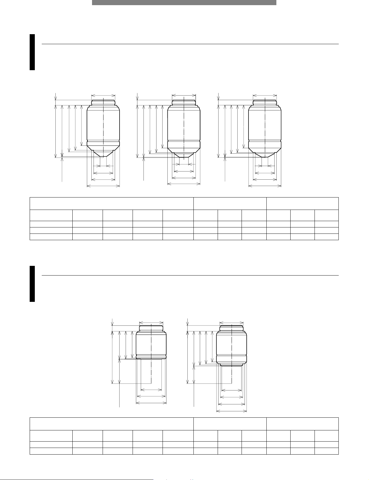
Super Long WD M Plan Achromat
SLMPlan series
Plan Achromat objective lenses with high magnification and super long working distance.
Two magnifications, 20x and 50x are available. For 5x or 10x objective lenses, select from the LMPLFLN series.
22.7
23.7
(23.95)
45
ø20.32
ø17.8
ø24.2
ø26
WD=21.05
4.9
26.4
28.1
29
(29.96)
45
ø20.32
ø17
ø19.3
ø22.7
ø26
4.9
WD=15.04
SLMPlan20x SLMPlan50x
SLMPlan 20x 0.35 21.0 9 73 200 1.1 7.2 200 1.3 7.2
SLMPlan 50x 0.45 15.0 3.6 91 500 0.44 2.9 500 0.53 2.9
Numerical
Aperture
Working distance
(mm)
Focal distance
f (mm)
Weight
(g)
Total
magnifications
Practical field
of view (mm)
Depth of
focus (µm)
Total
magnifications
Practical field
of view (mm)
Depth of
focus (µm)
UIS objective lenses
Widefield eyepiece WHN10x
Field Number 22
Super widefield eyepiece SWH10x
Field Number 26.5
Objective lens
(magnification)
Screw: W20.32x0.706 (0.8"x1/36")
Page 14
13
UIS OBJECTIVE LENSES
IR Long WD M Plan SemiApochromat/IR M Plan SemiApochromat
LMPlan-IR series/MPlan-IR
IR objective lenses which compensate for aberrations from visible to near infrared light.
Ideal for the observations of semiconductor interiors and the back surface of a chip package as well as CSP bump inspection.
34.3
30.3
22.5
ø
21
ø
26
(26.5)
WD=18.5
25
23
ø12.4
ø
15
ø
22
45
4.5
(36.9)
ø
20.32
ø
20.32
ø10.4
ø
18
ø
26
45
4.5
45
WD=20
(25)
ø
20.32
WD=8.1
ø
26
4.5
ø14.8
ø
18.12
(44.7)
ø12.5
4.5
45
WD=0.3
43.4
42.6
36.8
ø
20.32
ø
15
37
45
4.5
ø
20.32
ø4.95
ø12.2
45
ø
26
ø
26
(39)
WD=6
37.5
36.9
32.9
ø12.5
ø15.6
ø
18
4.7
ø
20.32
(41.6)
WD=3.4
40.8
ø
26
LMPlan5xIR LMPlan10xIR LMPlan20xIR
LMPlan50xIR LMPlan100xIR
Unit: mm
MPlan100xIR
LMPlan 5xIR 0.10 20.0 36 73 50 4.4 98
LMPlan 10xIR 0.25 18.5 18 73 100 2.2 18
LMPlan 20xIR 0.40 8.1 9 110 200 1.1 6.1
LMPlan 50xIR 0.55 6.0 3.6 115 500 0.44 2.2
LMPlan 100xIR 0.80 3.4 1.8 122 1000 0.22 0.87
MPlan 100xIR 0.95 0.3 1.8 130 1000 0.22 0.67
Numerical
Aperture
Working distance
(mm)
Focal distance
f (mm)
Weight
(g)
Total
magnifications
Practical field of
view (mm)
Depth of focus
(µm)
UIS objective lenses
Widefield eyepiece WHN10x
Field Number 22
Objective lens
(magnification)
Screw: W20.32x0.706 (0.8"x1/36")
Page 15

UIS2 OBJECTIVE LENSES
14
M Plan SemiApochromat BD (BD:Brightfield/Darkfield)
MPLFLN-BD series
Plan SemiApochromat objective lenses, giving high-level correction for chromatic aberration.
The series secures a W.D. of 1mm or longer. Since the exit pupil position of the 5x-150x objective lenses is standardized, the
position of the DIC prism does not have to be switched when changing the magnification.
MPLFLN 5xBD 0.15 12.0 36 95.5 50 4.4 59 50 5.3 59
MPLFLN 10xBD 0.30 6.5 18 82.8 100 2.2 15 100 2.7 15
MPLFLN 20xBD 0.45 3.0 9 87.7 200 1.1 5.2 200 1.3 5.2
MPLFLN 50xBD 0.80 1.0 3.6 99.8 500 0.44 1.3 500 0.53 1.3
MPLFLN 100xBD 0.90 1.0 1.8 98.9 1000 0.22 0.73 1000 0.27 0.73
MPLFLN 150xBD 0.90 1.0 1.2 104.8 1500 0.15 0.6 1500 0.18 0.6
Numerical
Aperture
Working distance
(mm)
Focal distance
f (mm)
Weight
(g)
Total
magnifications
Practical field
of view (mm)
Depth of
focus (µm)
Total
magnifications
Practical field
of view (mm)
Depth of
focus (µm)
UIS2 objective lenses
Widefield eyepiece WHN10x
Field Number 22
Super widefield eyepiece SWH10x
Field Number 26.5
Objective lens
(magnification)
Screw: W26x0.706
Unit: mm
ø26 ø26 ø26
ø16
ø22.4
ø29.5
ø32
ø22
ø16.8
ø26.2
ø27
ø32
ø22
ø17
ø27.5
ø28.5
ø32
4.5
WD=12
WD=6.5
45
(33)
31.5
31
30.25
(38.5)
4.545
37
36.5
34.1
4.5
(42)
45
39.5
39
35.97
WD=3
ø26
ø26
ø26
ø20
ø27.2
ø32
ø20
ø27.2
ø32
ø27.2
ø20
ø32
(44)
4.5
WD=1
45
41
4.5
WD=1
WD=1
45
(44)
41
4.5
45
(44)
41
MPLFLN5xBD MPLFLN10xBD MPLFLN20xBD
MPLFLN50xBD MPLFLN100xBD MPLFLN150xBD
Page 16

15
UIS2 OBJECTIVE LENSES
Screw: W26x0.706
Unit: mm
MPLFLN 5xBDP 0.15 12.0 36 95.5 50 4.4 59 50 5.3 59
MPLFLN 10xBDP 0.25 6.5 18 83.3 100 2.2 18 100 2.7 18
MPLFLN 20xBDP 0.40 3.0 9 88.5 200 1.1 6.1 200 1.3 6.1
MPLFLN 50xBDP 0.75 1.0 3.6 100.5 500 0.44 1.4 500 0.53 1.4
MPLFLN 100xBDP 0.90 1.0 1.8 101.5 1000 0.22 0.73 1000 0.27 0.73
Numerical
Aperture
Working distance
(mm)
Focal distance
f (mm)
Weight
(g)
Total
magnifications
Practical field
of view (mm)
Depth of
focus (µm)
Total
magnifications
Practical field
of view (mm)
Depth of
focus (µm)
UIS2 objective lenses
Widefield eyepiece WHN10x
Field Number 22
Super widefield eyepiece SWH10x
Field Number 26.5
Objective lens
(magnification)
MPLFLN5xBDP MPLFLN10xBDP MPLFLN20xBDP
MPLFLN50xBDP MPLFLN100xBDP
ø26 ø26 ø26
ø22.4
ø16
ø29.3
ø32
ø26
ø22
ø16.8
ø27
ø32
ø27.5
ø22
ø17
ø28.5
ø32
45
WD=12
WD=6.5
WD=3
4.5
(33)
31.5
31
30.25
(38.5)
4.545
37
36.5
34.1
4.5
(42)
39.5
39
35.97
45
ø26
ø26
ø32
ø27.5
ø20
ø32
ø27.5
ø20
WD=1
WD=1
(44)
4.545
41
4.545
(44)
41
M Plan SemiApochromat BDP (BDP:Brightfield/Darkfield/Polarizing)
MPLFLN-BDP series
Plan SemiApochromat objective lenses, giving high-level correction for chromatic aberration. The series secures a W.D. of
1mm or longer. Since the exit pupil position of the 5x-100x objective lenses is standardized, the position of the DIC prism
does not have to be switched when changing the magnification. The BDP series optimizing brightfield/darkfield and polarized
light characteristics is perfect for Nomarski DIC and polarized light observations
Page 17

UIS2 OBJECTIVE LENSES
16
Long WD M Plan SemiApochromat BD
LMPLFLN-BD series
Long working distance Plan SemiApochromat objective lenses, giving high-level correction for chromatic aberration.
Suitable with samples having a height difference and in preventing collision, as the working distance is long.
Also, since the exit pupil position of the 5x-100x objective lenses is standardized, the position of the DIC prism does not have to be
switched when changing the magnification.
LMPLFLN 5xBD 0.13 15.0 36 81 50 4.4 70 50 5.3 70
LMPLFLN 10xBD 0.25 10.0 18 84 100 2.2 18 100 2.7 18
LMPLFLN 20xBD 0.40 12.0 9 86 200 1.1 6.1 200 1.3 6.1
LMPLFLN 50xBD 0.50 10.6 3.6 85 500 0.44 2.5 500 0.53 2.5
LMPLFLN 100xBD 0.80 3.3 1.8 102 1000 0.22 0.87 1000 0.27 0.87
Numerical
Aperture
Working distance
(mm)
Focal distance
f (mm)
Weight
(g)
Total
magnifications
Practical field
of view (mm)
Depth of
focus (µm)
Total
magnifications
Practical field
of view (mm)
Depth of
focus (µm)
UIS2 objective lenses
Widefield eyepiece WHN10x
Field Number 22
Super widefield eyepiece SWH10x
Field Number 26.5
Objective lens
(magnification)
Screw: W26x0.706
Unit: mm
LMPLFLN5xBD LMPLFLN10xBD LMPLFLN20xBD
LMPLFLN50xBD LMPLFLN100xBD
45
WD=15
(30)
ø26
ø16.2
ø22.4
ø28
ø29.5
ø32
26.6
26.2
24
WD=10 (35)
45
ø26
ø15.5
ø21.9
ø28.2
ø30
ø32
32.3
32
30.2
4.5
5
WD=12
(33)
45 4.5
ø26
ø22
ø23
ø28
ø30
ø32
32.5
32.2
31.3
WD=3.3 (41.7)
45 4.7
ø26
ø21
ø29
ø32
37.7
37.3
36.5
ø30.3
ø26
ø23
ø20.7
ø28
ø32
WD=10.6
45
4.8
(34.4)
33
32.7
31.8
Page 18

UIS2 OBJECTIVE LENSES
17
M Plan Achromat BD
MPLN-BD series
Plan Achromat objective lenses providing excellent image flatness up to F.N. 22.
MPLN 5xBD 0.10 12.0 36 137 50 4.4 98
MPLN 10xBD 0.25 6.5 18 155 100 2.2 18
MPLN 20xBD 0.40 1.3 9 162 200 1.1 6.1
MPLN 50xBD 0.75 0.38 3.6 157 500 0.44 1.4
MPLN 100xBD 0.90 0.21 1.8 160 1000 0.22 0.73
Numerical
Aperture
Working distance
(mm)
Focal distance
f (mm)
Weight
(g)
Total
magnifications
Practical field of
view (mm)
Depth of focus
(µm)
UIS2 objective lenses
Widefield eyepiece WHN10x
Field Number 22
Objective lens
(magnification)
Screw: W26x0.706
Unit: mm
MPLN10xBD MPLN20xBD
MPLN100xBD
ø26 ø26
ø26
ø32
ø30.5
ø29.3
ø16
ø32
ø32
ø29
ø23.6
ø17
ø27
ø26
ø22
ø16.8
4.5
WD=12
45
(33)
31.5
31
30.25
45
(38.5)WD=6.5
4.5
37
36.5
34.01
(4.5)
WD=1.3 (43.7)
45
42.5
41
ø26
ø26
ø29
ø32
ø23.1
ø20.7
ø10
ø29
ø32
ø27
ø23
ø10
WD=0.38
(44.62)
45
4.5
43.68
42.5
41
WD=0.21 (44.79)
45
4.5
43.71
42.5
41
43.33
MPLN5xBD
MPLN50xBD
Page 19

18
UIS OBJECTIVE LENSES
ø26
41
42.5
43.2
(44.69)
4.5
WD=0.31
ø10
ø23
ø27
ø29
ø32
45
MPlanApo100xBD
M Plan Apochromat BD
MPlanApo-BD
Highest class Plan Apochromat objective lens that maximize performance in brightfield and darkfield observations.
All aberrations are corrected at the highest level, while providing high N.A.
MPlanApo100xBD 0.9 0.31 1.8 180 1000 0.22 0.59 1000 0.27 0.59
Numerical
Aperture
Working distance
(mm)
Focal distance
f (mm)
Weight
(g)
Total
magnifications
Practical field
of view (mm)
Depth of
focus (µm)
Total
magnifications
Practical field
of view (mm)
Depth of
focus (µm)
UIS objective lenses
Widefield eyepiece WHN10x
Field Number 22
Super widefield eyepiece SWH10x
Field Number 26.5
Objective lens
(magnification)
Screw: W26x0.706
Unit: mm
Page 20

BXFM frame
BXFM-F
Widely used system that allows use in combination with fiber illumination, motorized revolving nosepiece and telan lens unit.
Can easily be integrated into other equipment. Attach to the equipment by rear bolt mounting screw or pillar mounting hole.
19
MICROSCOPE SYSTEM BXFM
Weight: 1.9kg Unit: mm
98 110
80
58.5
0.5
(13)
(13)
55
23 7
4–M4 depth9
4–M4 depth7
Pillar mount hole center
66.2
16 17 17 34
36
35
82
4-M8 depth8
(Bolt mount screw)
0.5 17 100
124
36
ø32H8
(Pillar mount hole)
84
Stroke
2A00002
Page 21

MICROSCOPE SYSTEM BXFM
20
BXFM
BXFM-F+BXFM-ILH+BXFM-ILHSPU
Accommodates the reflected light brightfield/darkfield and fluorescence illuminators.
Weight: 3.2kg Unit: mm
11
Light axis
Light axis
165
130
83
45 40
72
23 7
3.5
Holder mounting position
Pillar axis
Revolving nosepiece mounting position
Objective lens
mounting position
Stroke
Specimen position
180
587
220 180
249
130
87.5
83
ø 32
40
3.5
45
165
11
17-47(stroke)
124
Specimen
surface
BXFM combination sample
BXFM-F+BXFM-ILH+BXFM-ILHSPU+TR30-2+BX-RLA2+U-LH100L-3
Weight: 8.2kg (exclude objective lens) Unit: mm* For installation dimensions, refer to those for the BXFM-F (page 19).
Page 22

MICROSCOPE SYSTEM BXFM
21
ø32
169
(Stroke)
19-49
124
84
208
290
204045
106 187
92.5
Specimen surface
BXFM-S combination sample
BXFM-F+BXFM-ILHS+TR30-2+U-KMAS+U-LH100L-3
Weight: 5.5kg (exclude objective lens) Unit: mm
BXFM-S
BXFM-F+BXFM-ILHS
Compact focusing unit suitable for building into existing equipment.
Weight: 2.4kg Unit: mm
20
Stroke
723
Light axis
45 40 84
141
59
106
Holder mounting position
Pillar axis
Revolving nosepiece
mounting position
Objective lens
mounting position
Specimen position
* For installation dimensions, refer to those for the BXFM-F (page 19).
Page 23

MICROSCOPE SYSTEM BXFM
22
U-ST
Compact stand
Weight: 5kg Unit: mmWeight: 1.8kg
106
73 143
88
ø110
133
ø32
49 133
20
35
ø40
130
503
ø25
Ø32
214~435
622
350
300
180º
90
50.5
30º
250
300
Stands
A wide variety of stands are available to suit different applications and purposes.
Item Specifications
1 Diameter of focusing arm or
ø32mm
fixing section of tube
2 Vertical pole diameter ø40mm
3 Horizontal poles diameters ø25mm
(both upper and lower poles)
4 Stroke Horizontal: 234mm,
Vertical: 205mm
5 Movement range Horizontal: 541 (435+106) mm max.
(Vertical pole —
BXFM-S optical axis)
6 Maximum specimen weight Forward: 10kg
(within 90-degree area)
Transverse direction: 6kg
Backward direction: 7kg
(at maximum stroke)
7 Weight 30kg
Major specifications
SZ2-STU2
Universal stand type 2
SZ-STL
Large stand
160
320
400
ø32
17.5
45
46
267
* The rotation angle of the horizontal arm can restrict to 90 degrees with stopper.
Page 24

ILLUMINATION UNITS
23
Universal reflected light illuminator
BX-URA2
Suitable for observations ranging from brightfield to fluorescence.
Six mirror units can be attached to this reflected light illuminator simultaneously.
Reflected light illuminator for BF/DF
BX-RLA2
ND filters are linked when exchanging between brightfield and darkfield.
Unit name Description Weight (g)
U-25LBD LBD filter slider 20
U-25IF550 IF550 filter slider 20
U-25ND6 ND filter 20
U-25ND25 ND filter 20
U-25FR Frost filter slider 20
U-25L42 UV-cut filter 20
U-PO3 Polarizer slider for reflected light 71
U-POTP3 Polarizer slider for reflected light 71
with tint plate
U-AN360-3 360° rotatable analyzer slider 79
U-AN Analyzer slider for reflected light 50
U-DICR DIC slider for reflected light 130
U-DICRH DIC slider for reflected light 130
(high resolution type)
U-DICRHC DIC slider for reflected light 130
(high contrast type)
Accessories
Unit name Description Weight (g)
U-25LBD LBD filter slider 20
U-25IF550 IF550 filter slider 20
U-25ND6 ND filter 20
U-25ND25 ND filter 20
U-25FR Frost filter slider 20
U-25L42 UV-cut filter 20
U-PO3 Polarizer slider for reflected light 71
U-POTP3 Polarizer slider for reflected light 71
with tint plate
U-AN360-3 360° rotatable analyzer slider 79
U-AN Analyzer slider for reflected light 50
U-DICR DIC slider for reflected light 130
U-DICRH DIC slider for reflected light 130
(high resolution type)
U-DICRHC DIC slider for reflected light 130
(high contrast type)
U-MBF3 Mirror unit for reflected brightfield 80
U-MDF3* Mirror unit for reflected darkfield 80
U-MDIC3 Mirror unit for reflected DIC 80
U-MBFL3 Mirror unit for reflected brightfield, 80
for high intensity light source
U-MWUS3 Fluorescence mirror unit for 80
reflected (U excitation)
U-MWBS3 Fluorescence mirror unit for 80
reflected (B excitation)
U-MWGS3 Fluorescence mirror unit for 80
reflected (G excitation)
Accessories
Unit: mm
Weight: 3.8kg
ø84
88
84
3.5
41
367
261
41
12
(17.9°)
76
11.6
17
11.6
86.8
27.2
(152)
135°
Illuminator
mounting
position
Revolving
nosepiece
mounting
position
31.5144
3046
ø75
88
108
38.7
56.829.4
16.2
12
13
11.8
1726
84
3.5
41
335
265
45
30107.5
7.5
17.5
35
Illuminator
mounting
position
Revolving
nosepiece
mounting
position
* U-RCV (DF converter for BX-URA2) is needed with darkfield observation.
Weight: 3.4kg
Page 25

ILLUMINATION UNITS
24
170 (Distance to the light axis)
Convex section(2-4) for positioning
3.5
Less than R6
21
82 (Revolving nosepiece relief dimension)
5
5.5
(6)
(11)
2.5
52 (Revolving nosepiece relief dimension)
100 (±0.1)
62 (±0.1)
37 ±0.1 (45° location face)
Location face
Location face
2
45° (±10')
4-M5 depth12 or more
36 (±0.1)
MOUNTING DIMENSIONS OF ILLUMINATORS (BX-RLA2, BX-URA2 and BX-KMA/BX-KMA-ESD)
Unit: mmFix illuminator using four M5 screws and projection for fastening.
Reflected light illuminators for BF
BX-KMA/BX-KMA-ESD
Enables brightfield, Nomarski DIC and simple polarizing observations. ESD model is also available.
Weight: 3.1kg
Unit: mm
* Combine SZX-TLGAD when using fiber illumination.
88
ø70
108
Cable length 260.5mm
312.5
250
30
84
3.5
41
Illuminator
mounting
position
Revolving
nosepiece
mounting
position
Unit name Description Weight (g)
U-25LBD LBD filter slider 20
U-25IF550 IF550 filter slider 20
U-25ND6 ND filter 20
U-25ND25 ND filter 20
U-25FR Frost filter slider 20
U-25L42 UV-cut filter 20
U-PO3 Polarizer slider for reflected light 71
U-POTP3 Polarizer slider for reflected light 71
with tint plate
U-AN360-3 360° rotatable analyzer slider 79
U-AN Analyzer slider for reflected light 50
U-DICR DIC slider for reflected light 130
U-DICRH DIC slider for reflected light 130
(high resolution type)
U-DICRHC DIC slider for reflected light 130
(high contrast type)
Accessories
Page 26

LAMP HOUSING & ACCESSORIES
25
Reflected light illuminator for BF
U-KMAS
Very compact reflected light illuminator with reduced depth.
Weight: 1.2kg
Unit: mm
ø75
88
198
155
21
64
6
21
Unit name Description Weight (g)
U-25LBD LBD filter slider 20
U-25IF550 IF550 filter slider 20
U-25ND6 ND filter 20
U-25ND25 ND filter 20
U-25FR Frost filter slider 20
U-25L42 UV-cut filter 20
U-PO3 Polarizer slider for reflected light 71
U-POTP3 Polarizer slider for reflected light 71
with tint plate
U-AN360-3 360° rotatable analyzer slider 79
U-AN Analyzer slider for reflected light 50
U-DICR DIC slider for reflected light 130
U-DICRH DIC slider for reflected light 130
(high resolution type)
U-DICRHC DIC slider for reflected light 130
(high contrast type)
Accessories
Page 27

LAMP HOUSING & ACCESSORIES
26
Lamp housings
Various different lamp housings are available, for use with different light sources: choose to suit the intended purpose.
Unit: mm
U-LH100HGAPO
100W mercury apo lamp housing
U-LH100HG
100W mercury lamp housing
U-LH75XEAPO
75W xenon apo lamp housing
U-LH100-3/U-LH100IR/U-LH100L-3
100W halogen lamp housings
Cable length 2,000mm Accepted lamp: UXL-75XB Weight: 3.1kg Cable length 2,000mm Accepted lamp: USH-103OL Weight: 2.7kg
Cable length U-LH100-3: 290mm
U-LH100IR: 290mm
U-LH100L-3: 800mm
Accepted lamp: 12V100WHAL (high intensity lamp)
12V100WHAL-L (long life lamp)
8
11575
180.5
169 (depth dimension for installation)
93
25°
55 6
30.2
30°
40.820
(148.5)
83.5
6565
60130
(30.2)(148.5)
93
169
(depth dimension for installation)
180.5
130
18.5
8
83.5
65
25°
65
40.8
30°
11575
20
135
(depth dimension for installation)
146.5
85.5 10737
Weight: 880g
* Power supply unit (BH2-RFL-T3 or U-RFL-T200) and power cable (UYCP) are necessary
for 100W mercury lamp housings. These items are sold separately.
BH2-RFL-T3: dimensions 120(W)x290(D)x225(H), weight approx 5kg/
U-RFL-T200 (for EU countries): dimensions 150(W)x295(D)x200(H), weight approx. 4.8kg
*Power supply unit (AH2-RX-T or U-RX-T200) and power cable (UYCP) are necessary for
75W xenon lamp housing. These items are sold separately.
AH2-RX-T: dimensions 120(W)x290(D)x186(H), weight approx. 4kg/
U-RX-T200 (for EU countries): dimensions 115(W)x195(D)x260(H), weight approx. 3kg
Note: Supplied by Olympus Life and Material Science Europa GmbH and its business
partners.
* External power supply (TH4-100 or TH4-200) and power cable (UYCP) are necessary for 100W halogen
lamp housings. These items are sold separately. For TH4-100/200 installation dimensions, refer to the next page.
Page 28

LAMP HOUSING & ACCESSORIES
27
31.5 (dimensions
for installation)
Darkfield light excluding tube
which is built into the BX-URA2.
(42.5)
2137.5
ø59
ø75
43
Lamp housing accessories
For the 100W halogen lamp, the external power supply TH4-100/200 with an intensity adjustment switch and an ON/OFF switch,
both are located close to the operator's hand, are provided. All Olympus reflected light illuminators can be used with fiber illumination.
Unit: mm
1,700
Unit: mm
Weight: 315g
U-RCV
DF converter for BX-URA2
U-RMT
Extension cord
Weight:200 g
Light guide mount hole ø12
Weight: 135g
SZX-TLGAD
Transmitted light guide adapter
U-LGAD
Fiber adapter for reflected light
observation
Light guide mount hole ø12
Weight: 390g
Weight: 2.2kg
TH4-100/200
External power supply
TH4-HS
Hand switch
Weight: 140g
14.575 200
120
125
42 38
18.5
77
Cable length:
2,000mm
26
24 (dimension
for installation)
44
ø30
ø12
ø49
* Mountable with BX-KMA/BX-KMA-ESD only.
51 (dimension
for installation)
62.5
ø67
ø59
ø32
Page 29

LAMP HOUSING & ACCESSORIES
28
Unit: mmUnit: mm
Weight: 1.6kg
Weight: 210g
LG-PS2*
Light source
LG-SF
Light guide
U-DULHA
Double lamp house adapter
8
76
235
251
10
10
126
86
130
ø15 (Light guide mounting position)
Groove: Width3, Depth1
10
ø10.1
ø13
ø12
ø25
ø15
30
31
61
25
20
1,000
*The types of model varies by country in use.
202
171
82
88
ø140
Weight: 1.2kg
Page 30

OBSERVATION TUBES
29
Weight: 350g
ø60
57.6
• For attachable video camera adapters, refer to video camera adapters system diagram page (pages 5-6).
U-TLU
Single port tube with lens
U-TLUIR
Single port tube with lens for IR
Widefield trinocular observation tubes
Trinocular observation tubes with widefield of view. Compatible with F.N. 22.
33.5 16 120
199.9
163.1
103.9
92
104.9
51.6
62.5
U-ETR-4
Widefield erect image trinocular tube
U-TR30-2/
Widefield binocular tube
U-TR30IR
Widefield binocular tube for IR
Single port tube with lens
When the visual observation is not needed and only video observation is required, a single port tube with a built-in telan lens
can be attached directly to the video port.
Unit: mm
Unit: mm
U-TR30-2 22 30 50-76 100/0, 20/80, 0/100 Inverted 1600
U-TR30IR 22 30 50-76 100/0, 0/100 Inverted 1600
U-ETR-4 22 30 50-76 100/0, 0/100 Erect 1900
Field Number
(F.N.)
Inclination angle
(degree)
Interpupillary distance
(mm)
Name
Light path selector
(eyepiece/video port)
Observation image
Weight
(g)
*Length marked with an asterisk (*) may vary according to interpupillary distance. The distance for figure shown is 62mm.
175
47.9
62.5 (IR: 64.5)
43.5
186.6 (IR: 188.9)
92.5* (IR: 93.9)
95.8
60.6
150.5
18
59.65
Page 31

30
OBSERVATION TUBES
117.223
61.981
139.400
88.000
2.837
70.330
149.081
20° 0' 0"
42° 0' 0"
95.929
101.929
318.527
328.338
337.718
72.200
Super widefield trinocular observation tubes
Trinocular observation tubes with super widefield of view. Compatible with F.N. 26.5.
55.6
79.6
180.8
49.968.6
98.8
173.8
220.8
82.3*
63.1
14
U-SWTR-3
Super widefield trinocular tube
MX-SWETTR
Super widefield erect image tilting trinocular tube
U-SWETR
Super widefield erect image trinocular tube
U-SWTR-3 26.5 24 50-76 100/0, 20/80, 0/100 Inverted 2300
U-SWETR 26.5 24 50-76 100/0, 0/100 Erect 4200
MX-SWETTR 26.5 0-42 50-76 100/0, 0/100 Erect 4200
Unit: mm
Field Number
(F.N.)
Inclination angle
(degree)
Interpupillary distance
(mm)
Name
Light path selector
(eyepiece/video port)
Observation image
Weight
(g)
*Length marked with an asterisk (*) may vary according to interpupillary distance. The distance for figure shown is 62mm.
73
83.4
92.9
6298.6
201.9
248.9
76.4*
2241936.5
Page 32

Intermediate tubes
Various accessories for various observation need.
31
INTERMEDIATE TUBES & ACCESSORIES
Unit: mm
Weight: 1.3kg
U-ECA
Magnification changer 2x
Provides 1x and 2x intermediate magnifications.
Weight: 1.3kg
U-CA
Magnification changer
Provides 1x, 1.2x, 1.6x and 2x intermediate magnifications.
Weight: 1.3kgBI:PT=100:0/20:80
U-TRU
Trinocular intermediate attachment
Intermediate attachment which divides the light path,
allowing attachment of both digital and video cameras.
ø140
150
88
52
37
183.9
106.9
52
37
150
ø140
58.2
ø138
96 42
ø70
ø75
45
42
Page 33

INTERMEDIATE TUBES & ACCESSORIES
32
Weight: 1kg
U-DP
Dual port
Use this intermediate tube to divide the light path.
Weight: 500g
U-DP1xC
Dual port 1x
Combine with U-DP to obtain a 1x image.
Weight: approximately 500g
U-EPA2
Eyepoint adjuster
Raises eyepoint by 30mm.
Weight: 1.2kg
U-APT
Arrow pointer
Projects an arrow into the field of view.
Unit: mm
88
38
51(mount face)
151
57
ø140
1-32UN
17.53
4.5
170.5(mount face)
182
ø44
ø25
ø44
ø30
0.92
(tolerence from light axis)
120
(45°)
45.3
15V0.2A
21.2 115
(8°)
45
89
30
88
Transmitted side port: side port = 100:0
Transmitted side port: side port = 70:30 (with use of U-MBF3)
Light path selector by mirror unit
Page 34

EYEPIECES/FILAR MICROMETER EYEPIECE
33
Eyepieces
Eyepieces for UIS2 optical system.
Filar micrometer eyepiece
U-OSM
Used for precise measurement in the field of view.
WHN10x
Widefield eyepiece
WHN10x-H
CROSSWHN10x
Widefield eyepieces
WH15x
Widefield eyepiece
SWH10x-H
MICROSWH10x
CROSSSWH10x
Super widefield eyepieces
(25) 18.7
43.7
29.6
ø36.5
ø41
36.8
EP
ø39
EP
ø43.2
ø46.2
ø30
(28.5)
53.2
41.4
69.9
60.2
ø30
ø41
ø38.5
ø41
ø38.5
39.6
39.4
48.6
62.6
51.2
48.6
28(23.1)
27.8(23.2)
ø30 ø30
29.5
60.9
41
65
75.5
Mounting position
(inside)
117.8
129.2
137
EP
23.5
30
Weight: 580g
Unit: mm
Unit: mm
Eyepiece Magnification 10✕, erect image (inverted when
used with erect image observation tube),
F.N. 14. Diopter adjustment range: ±5 1/m.
Provided with rubber eye shade.
Measuring scale Scale lines graduated in increments of 1mm in
the entire 10mm length. Shift of scale lines: 1mm
per rotation of the shift ring, the circumference of
which is divided into 100 graduations.
Measuring range 10mm/objective lens magnification
±5% by combined use of the zoom
compensation ring and the provided stage
micrometer. Compensation ring clamping screw.
Magnification compensation scale.
Actual size
Actual size (mm) =
Measured value (mm)
Objective lens magnification
Repeatability
Repeatability error ±
0.007
mm
A
(A …Objective lens magnification)
Accuracy *Measuring error
(A …Objective lens magnification:
L …Measured length in mm)
±[ (0.0002✕A+0.002) L +
0.007
] mm
A
Compensation
limit for objective
lens magnification
tolerance
*EP=eyepoint
WHN10x 22 — 24 90
WHN10x-H 22 -8 — +5 24 170 With adjustable diopter
CROSSWHN10x 22 -8 — +5 — 170
With cross lines and adjustable diopter
WH15x 14 — 24 90
SWH10x-H 26.5 -8 — +2 — 210 With adjustable diopter
MICROSWH10x 26.5 -8 — +2 — 210
With micrometer and adjustable diopter
CROSSSWH10x 26.5 -8 — +2 — 210
With cross lines and adjustable diopter
Field
Number
Diopter
adjustment range
(1/m)
Micrometer
diameter (mm)
Weight
(g)
Name Remarks
Page 35

REVOLVING NOSEPIECES
U-P4RE
Centerable quadruple revolving nosepiece with
slider slot for DIC
U-P6RE
Centerable sextuple revolving nosepiece with slider slot for DIC
Weight: 1kg Weight: 1kg
104
(114.4)
38
40
48.2
76.4
ø102.4
116.5
40
47.2
(125.6)
38 87.6
ø116.5
34
116.5
40
ø116.5
(125.6)
38 87.6
47.2
Revolving nosepieces for BF objective lenses
Choose from following 6 types. For motorized nosepieces, refer to motorized unit page.
U-D6RE
Sextuple revolving nosepiece with slider slot for DIC
U-D6RE-ESD
Sextuple revolving nosepiece with slider slot for DIC
with ESD treatment
ø84
40.8
26.5 60.9
(87.4)
40
83
ø102.4
104
40
48.2
(114.4)
38 76.4
Weight: 520g Weight: 800g Weight: 980g
U-5RE-2
Quintuple revolving nosepiece
Unit: mm
U-D7RE
Septuple revolving nosepiece with slider slot for DIC
Insert the DIC dummy when not using the DIC slider
Page 36

REVOLVING NOSEPIECES
U-D6BDRE
U-D6BDRE
35
Revolving nosepieces for BF/DF objective lenses
Choose from following 3 types. Use of adapter to mount BF objectives (BD-M-AD) enables attachment of brightfield objective
lenses. For motorized nosepieces, refer to motorized unit page.
U-5BDRE
Quintuple revolving nosepiece for BF/DF
U-D6BDRE
Sextuple revolving nosepiece for BF/DF
with slider slot for DIC/
U-P5BDRE
Centerable quintuple revolving nosepiece
BD-M-AD
Adapter to mount BF objectives
Weight: 800g Weight: 1kg
U-D5BDRE
Quintuple revolving nosepiece for BF/DF
with slider slot for DIC
Weight: 800g
Weight: 10g
Unit: mm
Insert the DIC dummy when not using the DIC slider
104
(111.2)
ø102.4
48.2
34.8 76.4
40
(114.4)
ø102.4
48.2
38 76.4
40
104
JAPAN
(125.6)
Ø116.5
47.2
38 87.6
40
U-D6BDRE
2A00002
JAPAN
116.5
W26✕0.706
W20.32✕0.706
0
+0.2
ø30
ø28.2
(4) 4
8
Page 37

36
2/3" CCD
1/2" CCD
Field of view (F.N.)
Projection area
Practical field of view (mm) =
Projection area (Field Number)
Objective lens magnifications
2/3" CCD 1/2" CCD 1/3" CCD
U-TV1x-2 1x 11 8 6
U-TV0.63xC 0.63x 17.5 12.7 9.5
U-TV0.5xC-3 0.5x 22 16 12
U-TV0.35xC-2 0.35x — 22 17.1
U-TV0.25xC 0.25x ——24
]Video camera adapter
(Projection lens)
Projection
magnifications
Projection area (F.N.)
Focus the video camera adapter to prevent defocusing the eyepiece image and defocusing by magnification switching.
Generally, the video camera adapter is focused by switching to a low magnification after focusing at a high magnification.objective lens.
C-mount video camera ports
Allows direct attachment of a C mount video camera. Four types are provided: 0.63x, 0.5x, 0.35x and 0.25x.
All models feature a focus adjustment function
U-TV0.25xC
C-mount video port with 0.25x lens
U-TV0.35xC-2
C-mount video port with 0.35x lens
U-TV0.5xC-3
C-mount video port with 0.5x lens
U-TV0.63xC
C-mount video port with 0.63x lens
Weight: 1.2kg Weight: 100g
Weight: 200g Weight: 430g
Unit: mm
ø36
ø64
147.3
17.53
1-32UN
156.84
3.5
ø
60
Image plane
1-32UN
ø60
17.53
12.4
4
22.4
Image plane
ø60
17.53
ø30
3.5
32.6
30.1
42.1
1-32UN
Image plane
78.25
68.75 3.5
ø30
17.53
Image plane
1002A0 0
ø60
1-32UN
VIDEO CAMERA ADAPTERS
Page 38

Video camera port
This port can be attached directly to the trinocular observation tube as well as to the single port tube with lens.
VIDEO CAMERA ADAPTERS
37
U-TV1x-2
Video port 1x
Video camera mount adapters
Allows attachment to video cameras with C, Bayonet, Sony and F mounts.
Use with the U-TV1x-2. Focus by amount of screwing into U-TV1x-2.
Unit: mm
Unit: mm
U-CMAD3
C-mount adapter
U-BMAD
Bayonet mount adapter
U-TMAD
T mount adapter
U-FMT
F/T mount adapter *
U-SMAD
Sony mount adapter
Weight: 70g Weight: 30g
* It must be combined with U-TMAD
Image plane
Image
plane
M56X2
49
ø42
ø64
48
30
3
ø64
ø48
60
38
40 4
Image plane
M56X2
17.53
M56X2
1-32UN
ø30
ø44.5
ø64.4
80.5
60.5
48.7
20
4
Image plane
4
23
43
ø64
ø42
M42X0.75
M56X2
55
ø54.7
ø45.7
13
46.5
Image plane
Weight: 165g Weight: 80g Weight: 90g
Weight: 150g
ø64
22
28
ø60
Page 39

MOTORIZED UNITS
38
(169)
844045
41
87
(487)
400
64.8
81.5
211.5
86.2
115
80
108
11.8
12
107
Illuminator cable length: 1.800mm Weight: 5.5kg(exclude objective lens)
Illuminator cable length: 1.800mm Weight: 4.3kg
BX-RLAA+U-D6REMC+U-LH100-3
Motorized BF/DF reflected light illuminator+motorized Nomarski DIC sextuple revolving nosepiece+100W halogen lamp housing
Enables motorized exchange of objective lenses, selection between brightfield and darkfield observations as well as aperture diaphragm
closing/opening. The BX-UCB control unit has an RS232C connector, allowing control via a PC.
For method of attaching illuminator, refer to page 24.
BX-RFAA
Motorized universal reflected light illuminator
Reflected light fluorescence illuminator with simultaneous attachment of six mirror units. Incorporates motorized mirror unit changeover and shutter.
Motorized units
Various motorized units, perfect for automation of equipment, are available.
Unit: mm
15
88
ø84
126
109.5
9276
87.5
41
11.6 17
86.8 27.2
135
371
261
11.6 12
41
14
Revolving
nosepiece
mounting
position
Illuminator
mounting
position
Page 40

MOTORIZED UNITS
39
68.3
190.5
115
U-D5BDREMC
Motorized quintuple BD revolving nosepiece with slider slot for DIC
U-D6REMC
Motorized sextuple revolving nosepiece with slider slot for DIC
U-P5REMC
Motorized centerable quintuple revolving nosepiece with slider slot for DIC
146
32
7°
105
108
332 (depth)
310
125
212
216
* Extension cord U-RMT (1700mm) should be used to connect the lamp housing (U-LH100-3) to the BX-UCB.
U-HSTR2
Hand switch
Weight: 1.0kg
Cable length 2000mm Weight: 370g
BX-UCB
Control unit
Motorized units including motorized illuminator and auto focus unit can be totally controlled
from BX-UCB
BX-REMCB
Control box for motorized nosepiece and BF/DF illuminator
BX-RLAA and U-D5BDREMC/U-D6REMC/U-P5REMC can be controlled from
U-HSTR2, or direct from the computer keyboard via an RS232C connector.
* BX-RFAA and U-D5BDREM/U-D6REM combination not applicable.
U-ACAD4515
AC adapter for BX-REMCB
Unit: mm
35±1
71±1
129.5±1
0
+100
2000
39.8
34
144
190.4
Weight: 1.1kg
Page 41

MOTORIZED UNITS
40
Unit: mm
ø78
R88
147.5
108
135
170.5
148
312.5
956
58.2
58.4
14.8
62.5
71
* Consult your Olympus dealer about the motorized focus.
Cable length: 2000mm
Weight: 3.3kg
U-AFA1M
Active auto focus unit
Weight: 1.0kg
U-FWR
Motorized reflected filter wheel
Accomplish maximum 6 filter position exchange
2000
147.9
180.5
130
58.5
24.5
42
30.5
Page 42

MOTORIZED UNITS
41
BXFMA-F
Motorized illumination with power focus
A motorized microscope unit for integration with your equipment. Motorized operations such as revolving nosepiece up/down, objective lens
switching, aperture diaphragm open/close, and brightfield/darkfield switching are accomplished with this component.
Several microscopic operations are totally controlled from an external unit by combining this component with an auto focus unit.
U-FH
Focus adjustment knob unit
U-IFFH
Focus adjustment knob interface
Unit: mm
Weight: 7.6kg
Weight: 1450g
Weight: 760g
* Consult your Olympus dealer about the mounting dimensions.
77
206
310.5
5656169
5177
75.5
5470 4
82.3
133
92
334
341.6
70
33.6
91.5
50
210
214
3
100
104
Page 43

DEEP ULTRAVIOLET OBSERVATION SYSTEM
42
Deep ultraviolet observation system
This module adds a deep ultraviolet (248nm) optical system to a general microscope.
An ultra-high resolution observation is executed by using an extremely short wavelength ray.
Unit: mm
108
258.5
69
79
ø8 (light guide)
3430.4
105.8
2000
+200
0
or 5000
+200
0
(39.5)6 5.5
ø70
196.8
196
ø30
ø39.4
1-32 UNF
(C Mount Thread)
45
(distance between
mounting positions)
102.5
U-UVF248IM
UV248 compatible intermediate tube
U-UVF2FB/5FB
UV quartz light guide
U-UVF248LB+U-LH80HGXE
UV248 compatible light source box + Mercury Xenon lamp housing
8170
227
41240
210.3
4-ø4.5, ø8 C'bore 5 Deep
4-ø4.5, ø13 C'bore 5 Deep
150
15045
18030
170
157.5
20
Weight: 1.9kg
Weight:6.5kg
Weight: U-UVF2FB 50g
U-UVF5FB 80g
Page 44

1. Field Number (F.N.) and Practical Field of View
The field number (F.N.) is referred to as the diaphragm size of
eyepiece in mm unit which defines the image area of specimen.
The diaphragm diameter actually seen through eyepiece is
known as the practical field of view (F.O.V.) which is determined
by the formula:
F.O.V. =
Eyepiece F.N.
(mm)
Objective lens magnification
2. Working Distance (W.D.)
The distance between the front edge of the objective lens and
the specimen surface (with the surface of the cover glass in case
of the cover glass objective lens) when the specimen is focused.
3. Parfocal Distance
It is the distance between the objective lens mounting plane and
the specimen. In UIS2/UIS objective lenses, the parfocal
distance is designed at 45mm.
For parfocal distance of the LCPLFLN-LCD series objective
lenses, refer to the appropriate objective lens page.
4. Relationship between the objective lens's focal length
and magnifications
Indicated magnifications of UIS2/UIS objective lenses are the
values when the focal length of the tube lens is 180 mm.
M
(ob)=
Focal length of tube lens
f
M(ob): Objective lens magnification
f: Objective lens's focal length
5. Total Magnification
5.1 Observation through eyepiece (binocular observation)
M(bino)=
M
(ob)×
M
(oc)
M(bino): Total magnification for binocular observation
M(ob): Objective lens magnification
M(oc)
: Eyepiece magnification
5.2 Video monitor observation
● Total magnification for video monitor
M(video monitor)=
M
(ob)×
M
(
video camera adapter
)×Monitor magnification*
M(video monitor)
: Total magnification on the video monitor
M(ob)
: Objective lens magnification
M(video camera adapter): Projected magnification for video camera
adapter including photo eyepiece
(refer to Figure 1)
* Refer to Figure 3 for "Monitor magnification"
● Practical field of view for video monitor observation
M
(ob): Objective lens magnification
M
(video camera adapter): Projected magnification for video camera
adapter including photo eyepiece
(refer to Figure 1 for projected magnifications)
* Refer to Figure 2 for image device size
Example
What is total magnifications for video monitor when objective
lens is 50x, video camera adapter U-TV0.5xC and 2/3" video
camera are used ?
OPTICAL TERMINOLOGY
43
Working distance and parfocal distance
Working Distance (W.D.)
Parfocal distance
Objective lens
mounting position
Focal plane
Figure 1 Video camera adapter and projection magnifications
Video camera adapter (Projection lens)
Projection magnifications
U-TV1x-1 + 1x
video camera mount adapters
U-TV0.63xC 0.63x
U-TV0.5xC-3 0.5x
U-TV0.35xC-2 0.35x
U-TV0.25xC 0.25x
Figure 2 Imaging device size
Camera format Diagonal Horizontal Vertical
1/3" 6.0mm 4.8mm 3.6mm
1/2" 8.0mm 6.4mm 4.8mm
2/3" 11.0mm 8.8mm 6.6mm
The above table is for standard image device sizes.
Check your device size for precise calculation.
Practical field of view for
=
Image device size *
video monitor observation
M(ob)×M(video camera adapter)
Figure 3 Imaging device size and monitor magnifications
Camera format
Monitor size (diagonal)
9" 12" 14" 21" 27"
1/3" 38.1x 50.8x 59.2x 84.6x 114.1x
1/2" 28.6x 38.1x 44.5x 63.5x 85.7x
2/3" 20.8x 27.7x 32.3x 46.2x 62.3x
Page 45

•Total magnification on the video monitor:
m(ob)=50×, M(video camera adapter) is 0.5× from Figure 1 and monitor
magnification is 46.2× from Figure 3.
M(monitor observation)=M(ob)×M(
video camera adapter
)×monitor magnification
=50×0.5×46.2=1155×
•Practical filed of view for video observation(horizontal side):
M(ob)=50×, M(video camera adapter) is 0.5× from Figure 1 and
horizontal side of 2/3" imaging device is 8.8mm from Figure 2
=
8.8 (mm)
=352µm
50 × 0.5
6. Numerical Aperture (N.A.)
The numerical aperture is a key factor to the performance of
objective lens (resolving power, focal depth and brightness).
The N.A. is determined by the following formula:
N.A.= n × sinθ
n=Refraction rate of the medium between specimen and
objective lenses. (Air: n=1, oil: n=1.515)
θ: Angle which is made by the optical axis and refraction of the
light farthest from the center of the lens.
The visual field brightness (B) of the microscope is determined
by the following formula in relation to the objective lens
magnification (M). The larger the N.A. and the lower the
objective magnification, brightness will increase in the factor of
the second power.
B
∝
N.A.
2
M
2
7. Resolving Power
The resolving power of an objective lens is measured by its
ability to differentiate two lines or points in an object. The greater
the resolving power, the smaller the minimum distance between
two lines or points that can still be distinguished. The larger the
N.A., the higher the resolving power.
● Resolving power formula
The following formula is generally used for determing resolution.
ε = 0.61 ×
λ
(
Reyleigh formula)
N.A.
λ: Wavelength or radiation in use
(λ=0.55µm is used for visible light)
N.A.: Objective lens N.A.
Example
MPLFLN100×(N.A.=0.90), λ=0.55µm
ε = 0.61 ×
λ =0.3355
=
0.3355
= 0.37µm
N.A. N.A. 0.90
8. Focal depth of Microscope
The focal depth refers to the depth of the specimen layer which
is in sharp focus at the same time, even if the distance between
the objective lens and the specimen plane is changed when
observing and shooting the specimen plane by microscope. As
human eyes are individually different in the ability of their focus
adjustment, each person's perception of the focal depth varies.
At present, the Berek formula is generally used, because it gives
a focal depth value that often coincides with that obtained
through experiments.
Focal depth formula
● Visual observation (Berek formula)
± D.O.F.=
ω× 250,000
+
λ
(µm)
N.A. × M 2(N.A.)
2
D.O.F.: Depth Of Focus
ω: Resolving power of eyes 0.0014
(when optical angle is 0.5 degrees)
M: Total magnification
(objective lens magnification x eyepiece magnification)
➔
± D.O.F. =
350 +0.275
(λ=0.55µm)
N.A. × M N.A.
2
This indicates that the focal depth becomes smaller as the
numerical aperture becomes larger.
Example
With MPLFLN100×(N.A.=0.90), WHN10×:
± D.O.F. =
350 +0.275
= 0.39 + 0.34 = 0.73µm
0.90 × 1,000 0.81
● Video camera
In the case of a video camera, the focal depth will vary according
to number of pixels of CCD, optical magnification, and numerical
aperture. The above-mentioned formula is used as a rough
guide only.
OPTICAL TERMINOLOGY
44
Objective
Numerical aperture
Sample
surface
n=1
(air)
θ
Practical field of view
=
Image device size
for video observation
M
(ob)
× M
(video camera adapter)
Page 46

9. Aberrations
A difference between an ideal image and an actual image that
passes through an optical system is called an “aberration.”
9.1 Requirements for Ideal Image Formation
The following three requirements must be satisfied to form an
image with no aberration, or an ideal image.
(i) All the light rays coming from a single point and passing
through an image formation optical system converge on a
single point.
(ii) Image points, which correspond to object points on the
same plane perpendicular to the optical axis, are present
on the same plane.
(iii) The planar shape of an object and the planar shape of an
image that are on the same plane perpendicular to the
optical axis have a similarity relation.
In an actual optical system, however, it is very difficult to strictly
meet the requirements for ideal image formation and this causes
“aberrations” that interfere with image forming performance.
9.2 Classification of Aberrations
Aberrations that interfere with image forming performance are
classified as shown below in Figure 9-2.
Seidel’s aberration = “Expansion of a point image” +
“Curvature of image plane” + “Deformation”
Types (1) to (3) correspond to “expansion of a point image” that
goes against requirement (i) for ideal image formation in Figure 9-
1. Type (4) corresponds to “curvature of image plane” that goes
against requirement (ii) in Figure 9-1. Type (5) corresponds to
“deformation” that goes against requirement (iii) in Figure 9-1.
Types (6) and (7) correspond to “color blur” of images caused by
characteristics of glass materials used for the optical system.
“Expansion of a point image” can also be expressed by
“wavefront aberration” that regards the light as “waves” and
takes account of the phase to include the influence of diffraction.
(1) Spherical aberration
When light rays coming out of an axial object point enter a lens,
the light rays with a larger numerical aperture (N.A.) are
subjected to stronger refraction power and cross the optical axis
in positions with larger differences from the ideal image
formation position. The aberration caused this way by different
image forming positions due to differences in N.A. of axial light
rays is called “spherical aberration.” (“Spherical aberration” is
proportional to the cube of N.A.)
It is said that objective lenses with larger N.A. have better
resolution but worsen spherical aberration. Our advanced
design and manufacturing techniques have realized good optical
performance even with large numerical aperture.
(2) Coma aberration
Even though spherical aberration is compensated to be very
small, there are cases where light rays coming out of an off-axis
object point are not condensed to a single point on the image
plane but generate asymmetric blur just like a comet leaving
traces. This is called coma aberration.
(3) Astigmatism
Even though a lens is compensated for spherical aberration and
coma aberration, there are cases where an image of an off-axis
object point is not focused to a single point but separated to a
concentric line image and a radial line image. This is called
“astigmatism.” When astigmatism is present, a point image
blurs vertically and horizontally, before and after the focus
position.
45
OPTICAL TERMINOLOGY
Object
(i)(ii)(iii)
Figure 9-1 Requirements for Ideal Image Formation
Image plane
Figure 9-3 Spherical Aberration
Specimen
Objective lens with
spherical aberration
Aplanatic
tube lens
Image plane
Figure 9-2 Classification of Aberrations
Seidel's
aberration
Aberration
Chromatic
aberration
(1) Spherical aberration
(2) Coma aberration
(3) Astigmatism
(4) Field curvature
(5) Distortion
(6) Longitudinal (axial)
chromatic aberration
(7) Chromatic aberration
of magnification
Figure 9-4 Coma Aberration and Spot Shape
on the Image Plane
Specimen Aplanatic
Objective lens with
coma aberration
tube lens
Image plane
Page 47

(4) Field curvature
An image plane of an object on a plane perpendicular to an
optical axis does not always become a plane perpendicular to
the optical axis, but it generally becomes a curved plane. This
symptom is called “field curvature.”
When field curvature is present, the image is more displaced as
it becomes closer to the periphery of the visual field. Therefore,
when the center of an image is brought into focus, blur occurs in
the peripheral areas of the image. To bring the entire image,
including the periphery, into clear focus, it is necessary to
adequately compensate for this type of aberration.
(5) Distortion
When there is no similar relation between a planar shape on an
object and a shape on the image plane, this is called “distortion.”
When distortion is present, a square image appears in a shape
of a barrel or pin-cushion as shown in Figure 9-6.
The microscope optical system contains some distortion. When
distortion is present, it can bring erroneous results of shape
measurements. When a microscope is used for precision
measurements, pay close attention to this aberration, for
example, by providing it with an aberration compensation
function.
(6) Chromatic aberration
Glasses used for optical systems have different refractive
indexes depending on the wavelength. This causes differences
in focal length between wavelengths and generates
displacement of image forming position. This phenomenon is
called “chromatic aberration,” which is sometimes subdivided
into axial displacement on the optical axis, called “axial
chromatic aberration” (or lateral chromatic aberration) and
displacement on the image plane, called “chromatic
aberration of magnitude.”
Many special glass materials are used, e.g., for apochromats
(MPlanApo in Olympus), to eliminate chromatic aberration in a
wide range from violet light (g-rays with wavelength of 435 nm)
to red light (c-rays with wavelength of 656 nm).
9.3 Wavefront Aberration
Since a long time ago, aberrations have been used in “geometric
optics,” which considers light as “light rays.” Microscope optical
systems are often used for observation of very small specimens
at a wavelength level, and sometimes adopt “wave optics,”
which regards light as “waves” and handles the phase
information, taking account of the influence of diffraction.
In such a case, “wavefront aberration” is used for evaluation.
As shown below, when requirements for ideal imaging are
satisfied in a microscope optical system, the spherical wavefront
(spherical waves) coming from a single point on an object
(specimen) is converted to plane waves through an ideal
objective lens. The plane waves are converted to spherical
waves through an ideal tube lens, and condensed to a single
point. The wavefront of these waves is called the “ideal
wavefront.”
Based on the figure indicated for (1) spherical aberration, the
behavior of the wavefront in an optical system that has an
aberration is described below.
A difference (a degree of disagreement) between the ideal
wavefront and the actual wavefront shown above is called
“wavefront aberration.”
46
OPTICAL TERMINOLOGY
Figure 9-5 Astigmatism and Change in Spot
Shape in Different Focus Positions
(a) (b) (c)
(a) (b) (c)
Figure 9-7 Ideal Microscope Optical System
Specimen Ideal
Spherical
Spherical
wave
wave
Ideal
objective
lens
Plane
Plane
wave
wave
tube lens
Spherical
wave
Image plane
Figure 9-6 Distortion
(a) Barrel shape
type
(a) Pin-cushion
type
Figure 9-8 Illustration of Wavefront Aberration
Actual
Specimen
Objective lens with
Objective lens with
spherical aberration
spherical aberration
wavefront
Ideal
wavefront
Page 48

Specifications are subject to change without any obligation on the part of the manufacturer.
Printed in Japan M1606E-1106B
•OLYMPUS CORPORATION has obtained ISO9001/14001.
 Loading...