

Page 1
j
MAINTENANCE / ON-SITE - MANUAL
Electro Surgical Generator
ESG-400
7.022.211 / ISSUE 5
Page 2
ESG-400
Indicates an imminently hazardous situation which, if not avoided, will result in
d
Indicates a potentially hazardous situation which, if not avoided, could result in
Indicates a potentially hazardous situation which, if not avoided, may result in
minor or moderate injury. It may also be used to alert against unsafe practices
The user must have received appropriate training in using, servicing,
Introduction
The intended use depends on the approval of the country. Refer to the instructions for use of the electrosurgical
unit.
Maintenance instructions
This maintenance manual contains essential information on using and maintaining this electrosurgical
generator safely and effectively. Instructions for the operation of this electrosurgical generator and related
danger, warnings and cautions concerning electrosurgery are beyond the scope of this maintenance manual.
Before using and maintaining, thoroughly review this manual and the instructions for use or maintenance
manuals of all equipment which will be used during maintenance. Use the equipment as instructed. Keep this
manual in a safe, accessible location. If you have any questions or comments about any information in this
maintenance manual, cont act O ly mpus.
Signal words
The following signal words are used throughout this maintenance manual:
INTRODUCTION
DANGER
WARNING
CAUTION
NOTE
User qualifications
The user must have received appropriate training in using this electrosurgical generator. The following
instructions are for use by qualified personnel only. Use of this maintenance manual by other individuals is
prohibited. The training will be provided by authorized representatives of Olympus during installation and
commissioning.
NOTE
Federal Law of the USA restricts this device to use by, or on the order of, a physician.
death or serious injury.
death or serious injury.
or potential equipment damage.
Indicates additional helpful information.
adjustment, updating and upgrading this electrosurgical generator.
7.022.211 / ISSUE 5 2 / 110 Introduction
Page 3

ESG-400
User
The safety and effectiveness of electrosurgical interventions depend not only o
the equipment used, but also to a major extent on factors which are under the control of the
user. It is therefore extremely important to read, understand and follow the instructions supplied
with the electrosurgical generator and the accessories in order to ensure safety and
effectiveness.
Always use the electrosurgical generator as outlined in this
will not only impede functions and prevent optimum performance, but may cause equipment
damage and
ications. Before each use, always inspect the equipment as outlined in
this
The electrosurgical generator and the footswitch must undergo a safety check in yearly intervals
in accordance with
Environmental
Be sure that this electrosurgical unit is not used adjacent to or stacked with other equipment
(other than the components of this electrosurgical unit or system) to avoid electromagnetic
interference.
Before use, thoroughly confirm the compatibility of all equipment.
To ensure electrical safety, the electrosurgical unit s hould not be used in conjunction w
The electrosurgical generator complies with the electromagnetic compatibility (EMC) standard.
Never
equipment. If an auxiliary computer system is in use together with the electrosurgical generator
and endoscopic imaging techniques, the image on the monitor might f
the instructions in “Electromagnetic Compatibility (EMC) information” in the Appendix of the
instruction for use regarding electromagnetic ambient conditions.
Never loop the cords (active cord, bipolar cord, neutral electrode cor
with cords belonging to other medical equipment. The high frequency s ignals or spark discharge
noise generated by the unit may interfere with the operation of other medical equipment.
Do not use the electrosurgical unit in a location exposed to strong electromagnetic radiation
(microwave or short-wave medical treatment equipment, Magnetic Resonance Imaging, radio or
mobile phone equipment). Electrosurgical unit malfunction can occur.
The elect rosurgi cal
should only be used under the conditions as described in chapter
1
equipment damage.
Precautions
High frequency leakage c urrent or spark discharge may cause user burns.
Follow the dangers, warnings and cautions given below when handling and servicing this electrosurgical unit.
This information is to be supplemented by the dangers, warnings and cautions given in each chapter.
-related error prevention
WARNING Improper use
n the design of
maintenance manual. Improper use
/ or compl
maintenance manual.
WARNING Annual safety checks / Inspection
the national statutory regulations (refer to chapter 7 “Inspection”).
conditions
CAUTION Interference of the unit with other equipment
ith:
• Electrical equipment whose safety against leakage current is not guaranteed.
• Electrosurgical equipment whose safety in com bined use is not guaranteed.
theless, when the electrosurgical generator is active it may disturb neighboring electronic
reeze or blackout. Follow
d) or bundle cords together
CAUTION Unsuitable temperature and humidity
generator
-3 (Limitations). Use under other conditions may impede normal performance and / or result in
7.022.211 / ISSUE 5 3 / 110 Introduction
Page 4

ESG-400
Accessories
Do not apply excessive bending, straining, or squeezing force to any cords. It may cause
malfunction.
The electrosurgical generator shall only be used with compatible accessories. When connecting
accessories (cords, electrodes, HF instruments) avoid output settings where the maximum
output voltage of the electrosurgical generator may exceed the rated accessory voltage (refer to
“Mode characteristics”, “Output characteristics” in the Appendix of the ins
instruction manual of the accessory). For a list of compatible neutral electrodes, refer to
“Specifications” in the Appendix of the instruction for use.
Before use, the electrosurgical unit and accessories must be examined for damage. All
communication cables and its plugs must be free of scratches and cracks. Cables and
accessories with damaged insulation or connections must not be used.
Electric shock
To prevent the risk of electric shock, the housing of the electrosurgical unit must be grounded.
Always connect the power cord plug to a properly grounded wall outlet. Do not use a
3
To prevent user shock, malfunction and damage of the electrosurgical unit, keep liquids away
from all electrical equipment.
When taking measurements or troubleshooting of the electrosurgical unit, take appropriate
precautions, such as using isolated tools and equipment, using the “one han
When the housing is opened, there is a danger of electric shock. The unit must only be serviced
by
Burns
The maximum output voltage characteristics of the electrosurgi
diagrams in “Output characteristics” in the Appendix of the instruction for use. When setting the
power level, first set it to a low level and increase it gradually. If the output is initially set to a high
level, the electro
or patient burns.
However, certain modes may present an unacceptable risk at low output power settings. For
example, with the PulseCut fast mode or PulseCut slow mode, the ris k of an excessive thermal
effect rises if the output power setting is too low. Therefore, it is recommended that you perform
basic testing before using the electrosurgical generator. If the instruction manual of the HF
instrument to be used stipulate a rated voltage, the output should
exceed that voltage.
High frequency, high voltage signals that can cause severe burns are present in the
monopolar
when testing and troublesho
WARNING
CAUTION Non-compatible accessories and accessory damage
WARNING Grounding failure
-pin / 2-pin adapter, as it can impair safe operation of the unit.
WARNING User shock
Mechanical stress
truction for use, and the
CAUTION Injury during servicing
authorized technicians.
WARNING User
cal generator are shown in the
de’s insulation may be damaged and cause user and /
be set so that it does not
/ bipolar sockets descri bed in thi s maintenance manual. Take appropriate precautions
oting this area of the electrosurgical unit.
7.022.211 / ISSUE 5 4 / 110 Introduction
d rule,” etc.
Page 5

ESG-400
Fire
The risk of flammable gases or other materials being ignited exists with any contact of electrical
energy. Precautionary measures must be taken to keep flammable materials and substances
away from an active electrosurgical unit (do not use flammable
oxygen). Otherwise, explosion or fire may result and cause serious injuries. This electrosurgical
uni
Flammable agents used for cleaning and disinfection must be allowed to evaporate before the
electrosurgical unit is used and servi
Non
Haz
The electrosurgical unit may be contaminated with infections materials; therefore, all surfaces of
the unit’s housing should be cleaned before servicing according to chapter
Should any abnormal output be suspected during operation, immediately terminate the use of
the equipment by releasing the footswitch. If the footswitch does not react, switch off the
electrosurgical unit. Otherwise, malfunction of the equipment m
in output.
Take additional precautions for service technicians, when using the unit’s service operation
mode (see chapter 15, Service operation mode).
To prevent electrosurgic
circuit electrodes (accessories, neutral
electrodes).
In the event of a defect or malfunction in the unit, an undesirably high output power may be
emitted.
Repairs must only be carried out by Olympus or a firm authorized by Olympus.
Preventive maintenance (inspection / periodic safety check) must only be carried out by a
qualifie
/ Explosion
DANGER Ignitable anaesthetics / fire supporting gases
anesthetics, nitrous oxide or
t is not explosion-proof. Do not use the unit within an explosion zone.
WARNING Ignitable cleaning- and disinfection agents
ced.
-flammable agents should be used for cleaning and disinfection wherever possible.
WARNING Risk of fire
Replace fuses as marked. The fuses
authorized technicians.
ards and complications
WARNING Contamination
1-8 (Cleaning).
WARNING Output performance
ay cause an unintended increase
WARNING
CAUTION Unit defect
DANGER Unit defect
Never use the electrosurgical unit if an abnorm ali ty is suspe cted.
Service persons
al unit damage, never short-
Repair and Maintenance
CAUTION Repair
CAUTION Maintenance
d person / technician.
7.022.211 / ISSUE 5 5 / 110 Introduction
Page 6

ESG-400
Copyright
©2011 Olympus Winter & Ibe GmbH. All rights reserved.
Unauthorized reproduction or distribution in part or in whole is prohibited.
Trademarks
OLYMPUS is a registered trademark of the Olympus Corporation.
The company names, product names, and proprietary technic al terms in this document are the trademarks or
registered trademarks of their respective owners.
7.022.211 / ISSUE 5 6 / 110 Introduction
Page 7

ESG-400
CONTENT
INTRODUCTION ................................................................................................................ 2
CONTENT .......................................................................................................................... 7
CHAPTER 1: PRODUCT SPECIFICATIONS .................................................................... 9
1 OUTLINE ...................................................................................................................... 10
1-1 Intended Use .................................................................................................................................... 10
1-2 Compatibility ..................................................................................................................................... 10
1-3 Expected service life ........................................................................................................................ 10
2 FEATURES ................................................................................................................... 11
2-1 Application Modes ............................................................................................................................ 11
2-2 Accessories ...................................................................................................................................... 12
3 LIMITATIONS ................................................................................................................ 13
4 SPECIFICATIONS ........................................................................................................ 14
4-1 ELECTROSURGICAL GENERATOR ESG-400 (REF: WB91051W) .............................................. 14
4-2 Power cords (4.5 m angled plug) ..................................................................................................... 15
4-3 Footswitch (REF: WB50402W, double pedal) ................................................................................. 16
4-4 Footswitch (REF: WB50403W, single pedal, optional) .................................................................... 16
4-5 Neutral electrode cable “P-cord” (REF: MAJ-814, optional) ............................................................ 16
4-6 Communication cable 0.25 m (REF: MAJ-18 71, optional) .............................................................. 17
4-7 Communication cable 10 m (REF: MAJ-1872, optional) ................................................................. 17
4-8 Adapter for UHI-2/3 (REF: MAJ-1873, optional) .............................................................................. 17
5 NAME AND FUNCTION OF EACH PART .................................................................... 18
5-1 Symbols and descriptions ................................................................................................................ 18
5-1-1 Safety related symbols ............................................................................................................ 18
5-1-2 Front panel .............................................................................................................................. 19
5-1-3 Touch screen ........................................................................................................................... 19
5-1-4 Rear panel ............................................................................................................................... 21
5-2 Front panel ....................................................................................................................................... 22
5-3 Rear panel ........................................................................................................................................ 24
5-4 Bottom panel .................................................................................................................................... 25
5-5 All screen ......................................................................................................................................... 25
5-6 Set screen ........................................................................................................................................ 26
5-7 Mode screen .................................................................................................................................... 27
5-8 Footswitch with two pedals .............................................................................................................. 28
5-9 Footswitch with one pedal (optional)................................................................................................ 28
5-10 Neutral electrode cable “P-cord” (optional) ...................................................................................... 29
6 CONNECTOR ............................................................................................................... 30
6-1 Docking Connector .......................................................................................................................... 30
6-2 Monopolar Standard 1 ...................................................................................................................... 30
6-3 Monoploar Standard 2 (Erbe) ........................................................................................................... 30
6-4 Bipolar Standard 3............................................................................................................................ 30
6-5 Monopolar Neutral Electrode ........................................................................................................... 31
6-6 Foot switch 1 (SIP/SOP) .................................................................................................................. 31
6-7 Foot switch 2 (SIP/SOP) .................................................................................................................. 32
7 SYSTEM DIAGRAM ..................................................................................................... 33
8 CLEANING, STORAGE AND DISPOSAL .................................................................... 34
8-1 Cleaning ........................................................................................................................................... 34
8-2 Storage ............................................................................................................................................. 35
8-3 Disposal of the unit .......................................................................................................................... 35
CHAPTER 2: BLOCK DESCRIPTION ............................................................................. 37
1 BLOCK DESCRIPTIONS .............................................................................................. 38
1-1 Motherboard ..................................................................................................................................... 39
1-2 HVPS Board ..................................................................................................................................... 41
1-3 Generator board ............................................................................................................................... 41
1-4 Relay Board ..................................................................................................................................... 41
1-5 Front Panel ....................................................................................................................................... 42
CHAPTER 3: REPAIR SYSTEM ...................................................................................... 43
7.022.211 / ISSUE 5 7 / 110 Content
Page 8

ESG-400
1 ESG-400 MAIN UNIT .................................................................................................... 44
2 BOARD COMPATIBILITY ............................................................................................. 44
3 OPTIONAL ACCESSORIES ......................................................................................... 44
3-1 WB50402W (Footswitch with two pedals) ....................................................................................... 44
3-2 WB50403W (Footswitch with one pedal) ......................................................................................... 44
3-3 MAJ-814 (Neutral electrode cable “P-cord”) .................................................................................... 44
4 PRECAUTIONS ON FUNCTION AND OPERATION SETTINGS ................................. 44
4-1 General Precautions ........................................................................................................................ 44
CHAPTER 4: TROUBLESHOOTING .............................................................................. 45
1 GENERAL ..................................................................................................................... 46
2 NEUTRAL ELECTRODE OPERATION ........................................................................ 47
3 ERROR SCREEN, CODES AND MEASURES ............................................................. 48
3-1 What to do when no error code is displayed .................................................................................... 50
3-2 What to do when an error code is displayed .................................................................................... 54
CHAPTER 5: INSPECTION ............................................................................................. 73
1 JIGS, TOOLS, AND MEASURING EQUIPMENT FOR INSPECTION .......................... 74
2 INSPECTION PROCEDURES ...................................................................................... 75
2-1 Visual inspection of the electrosurgical generator and accessories ................................................ 76
2-2 Verifying the contact quality monitor function .................................................................................. 80
2-3 Checking the DC resistance (according to IEC 60601-2-2) ............................................................. 82
2-4 Checking the earth resistance (according to IEC 60601-1 and IEC 62353) .................................... 82
2-5 Checking the earth leakage current (according to IEC 60601-1) .................................................... 82
2-6 Checking the patient leakage current (according to IEC 60601-1) .................................................. 83
2-7 Checking the current and power consumption and output waveform .............................................. 84
2-8 Checking the high frequency leakage current (according to IEC 60601-2-2) .................................. 86
2-8-1 Measurement of the monopolar high frequency leakage current under loaded condition ...... 86
2-8-2 Measurement of the monopolar high frequency leakage current under unloaded condition .. 88
2-8-3 Measurement of the bipolar high frequency leakage current under loaded condition ............ 90
2-8-4 Measurement of the bipolar high frequency leakage current under unloaded condition ........ 92
2-9 Checking the output power .............................................................................................................. 94
2-10 Checking for certain features and error messages .......................................................................... 94
2-11 Final test ........................................................................................................................................... 95
2-11-1 Self test.................................................................................................................................... 95
2-11-2 Display and sound check ........................................................................................................ 95
2-11-3 Functionality of push buttons .................................................................................................. 95
2-11-4 Communication test ................................................................................................................. 95
2-11-5 Restore of output power settings ............................................................................................ 96
2-12 Inspection label (For applicable markets) ........................................................................................ 96
3 INSPECTION CARD ..................................................................................................... 97
CHAPTER 6: DEVICE MENU ........................................................................................ 103
1 SAFETY TEST ............................................................................................................ 104
2 SOFTWARE VERSION ............................................................................................... 105
CHAPTER 7: REVISION HISTORY ............................................................................... 107
3 REVISION HISTORY .................................................................................................. 108
7.022.211 / ISSUE 5 8 / 110 Content
Page 9

ESG-400
CHAPTER 1: PRODUCT SPECIFICATIONS
1 OUTLINE ...................................................................................................................... 10
1-1 Intended Use .................................................................................................................................... 10
1-2 Compatibility ..................................................................................................................................... 10
1-3 Expected service life ........................................................................................................................ 10
2 FEATURES ................................................................................................................... 11
2-1 Application Modes ............................................................................................................................ 11
2-2 Accessories ...................................................................................................................................... 12
3 LIMITATIONS ................................................................................................................ 13
4 SPECIFICATIONS ........................................................................................................ 14
4-1 ELECTROSURGICAL GENERATOR ESG-400 (REF: WB91051W) .............................................. 14
4-2 Power cords (4.5 m angled plug) ..................................................................................................... 15
4-3 Footswitch (REF: WB50402W, double pedal) ................................................................................. 16
4-4 Footswitch (REF: WB50403W, single pedal, optional) .................................................................... 16
4-5 Neutral electrode cable “P-cord” (REF: MAJ-814, optional) ............................................................ 16
4-6 Communication cable 0.25 m (REF: MAJ-18 71, optional) .............................................................. 17
4-7 Communication cable 10 m (REF: MAJ-1872, optional) ................................................................. 17
4-8 Adapter for UHI-2/3 (REF: MAJ-1873, optional) .............................................................................. 17
5 NAME AND FUNCTION OF EACH PART .................................................................... 18
5-1 Symbols and descriptions ................................................................................................................ 18
5-1-1 Safety related symbols ............................................................................................................ 18
5-1-2 Front panel .............................................................................................................................. 19
5-1-3 Touch screen ........................................................................................................................... 19
5-1-4 Rear panel ............................................................................................................................... 21
5-2 Front panel ....................................................................................................................................... 22
5-3 Rear panel ........................................................................................................................................ 24
5-4 Bottom panel .................................................................................................................................... 25
5-5 All screen ......................................................................................................................................... 25
5-6 Set screen ........................................................................................................................................ 26
5-7 Mode screen .................................................................................................................................... 27
5-8 Footswitch with two pedals .............................................................................................................. 28
5-9 Footswitch with one pedal (optional)................................................................................................ 28
5-10 Neutral electrode cable “P-cord” (optional) ...................................................................................... 29
6 CONNECTOR ............................................................................................................... 30
6-1 Docking Connector .......................................................................................................................... 30
6-2 Monopolar Standard 1 ...................................................................................................................... 30
6-3 Monoploar Standard 2 (Erbe) ........................................................................................................... 30
6-4 Bipolar Standard 3............................................................................................................................ 30
6-5 Monopolar Neutral Electrode ........................................................................................................... 31
6-6 Foot switch 1 (SIP/SOP) .................................................................................................................. 31
6-7 Foot switch 2 (SIP/SOP) .................................................................................................................. 32
7 SYSTEM DIAGRAM ..................................................................................................... 33
8 CLEANING, STORAGE AND DISPOSAL .................................................................... 34
8-1 Cleaning ........................................................................................................................................... 34
8-2 Storage ............................................................................................................................................. 35
8-3 Disposal of the unit .......................................................................................................................... 35
7.022.211 / ISSUE 5 9 / 110 Chapter 1: PRODUCT SPECIFICATIONs
Page 10

ESG-400
1-1 Intended Use
The intended use depends on the approval of the country. Refer to the instructions for use of the electrosurgical
generator.
1-2 Compatibility
This product can be used in combination with the products listed in compatibility table.
1-3 Expected service life
The expected service life is 10 years.
1 Outline
7.022.211 / ISSUE 5 10 / 110 Chapter 1: PRODUCT SPECIFICATIONs
Page 11

ESG-400
2 Features
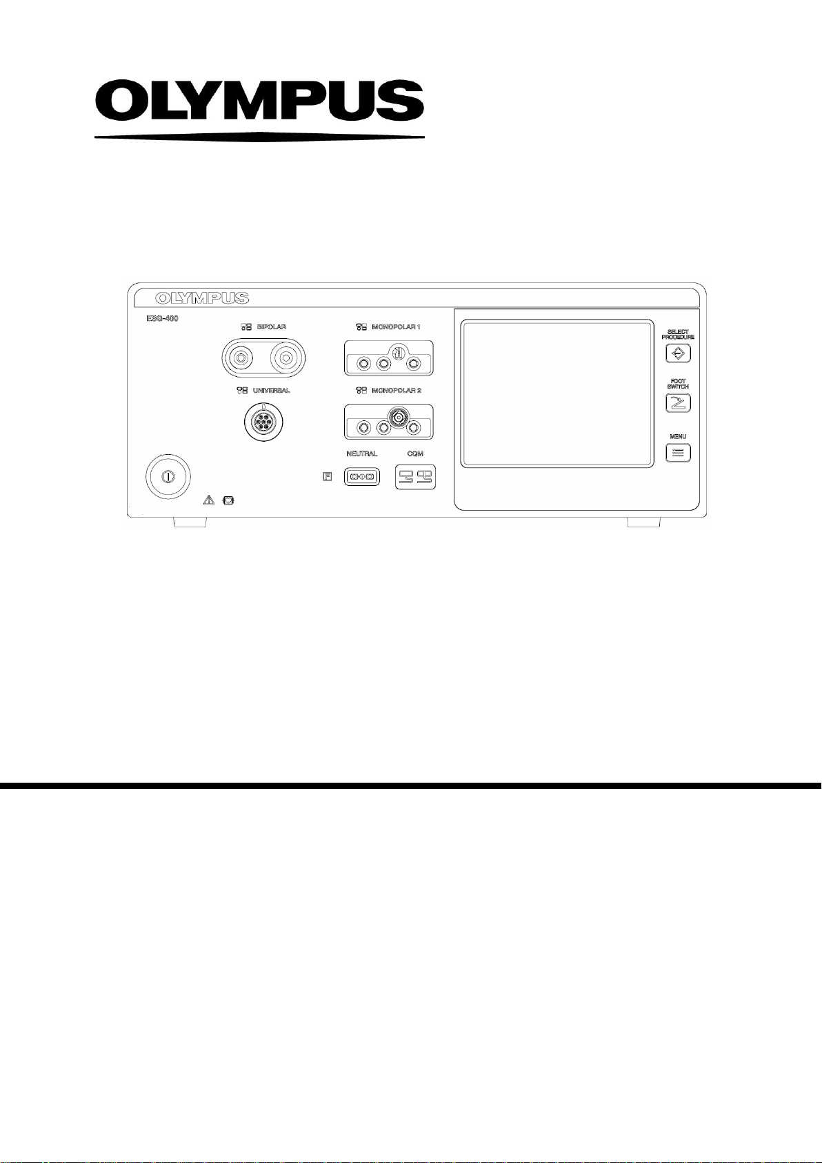
The ESG-400 is a reusable, non-sterile electrosurgical generator with different mono- and bipol ar cutting and
coagulation modes. The maximum output power is 320 W.
On the front side it features a touch screen display that displays the connection status of accessories and
peripherals connected to the electrosurgical generator. It is also used to show and modify the output settings
(e.g. mode, output power, effect) as well as to control other functions (e.g. save settings).
In addition the ESG-400 has a bipolar socket, two monopolar sockets, a neutral electrode socket, and a
universal socket to connect applicators with instrument recognition. The power switch turns the generator on
and off.
Two contact quality indicators (one for split and one for non-split electrodes) are green illuminated if neutral
electrodes are correctly connected. Three additional push buttons allow recalling a previously saved setting
(Select Procedure), to assign the footswitches to specific output sockets (Footswitch), and to control several
other functions (Menu), e.g. select language, touch tone control, output volume, or brightness.
On the rear panel the volum e control, a ventilation hole, the equipotential bonding point, the AC power socket,
and two footswitch sockets can be found. Furthermore, for the connection of peripheral equipment 26-pin plugs
respectively 14-pin plugs can be connected to the LINK-IN or to the LINK-OUT socket.
On the bottom panel, a docking socket is featured. It can be used to connect the ESG-400 directly to the
USG-400 and upcoming devices . The ESG-400 is compatible with the new USG-400 ultrasonic generator to
enable the use of combined (US + HF) instruments.
2-1 Application Modes
Monopolar Cut:
• PureCut (Cutting of varying tissue structures; 3 Effects)
• BlendCut (Cutting of varying tissue structures; 3 Effects)
• PulseCut slow (Intermittent cutting; 3 Effects)
• PulseCut fast (Intermittent cutting; 3 Effects)
Monopolar Coagulation:
• SoftCoag (Coagulation of tissue with little sticking and carbonization; 3 Effects)
• ForcedCoag (Fast and effective coagulation; 3 Effects)
• SprayCoag (Contact-free surface coagulation with little penetration depth; 3 Effects)
• PowerCoag (Fast and effective coagulation with increased dissection capabilities; 3 Effects)
7.022.211 / ISSUE 5 11 / 110 Chapter 1: PRODUCT SPECIFICATIONs
Page 12

ESG-400
Bipolar Cut:
• BipolarCut (All bipolar cutting procedures of tissue structures; 3 Effects)
• SalineCut (Cutting in conductive fluid; 3 Effects; only available via UNIVERSAL socket)
• PK PureCut (Cutting of varying tissue structures; 3 Effects; only available via UNIVERSAL socket)
• PK SoftCut (Cutting of varying tissue stru cture s; 3 Effects; only available via UNIVERSAL socket)
• PK LoopCut (Cutting of varying tissue structures, especially fibroid tissue; 3 Effects; on ly avai lab le via
UNIVERSAL socket)
• PK MorceCut (Cutting of varying tissue structures, especially fibroid tissue; 3 Effects; only available
via UNIVERSAL socket)
Bipolar Coagulation:
• BiSoftCoag (Coagulation with little sticking and carbonization; 3 Effects)
• AutoCoag (Coagulation with little sticking and carbonization; 3 Effects)
• SalineCoag (Coagulation in conductive fluid; 3 Effects; only available via UNIVERSAL socket )
• HardCoag (Controlled tissue coagulation; 3 Effects)
• RFCoag (Controlled deep tissue coagulation; with and without RCAP)
• FineCoag (Coagulation of tissue with little sticking and carbonization; 1 Effect)
• PK Coag (Coagulation of tissue with little sticking and carbonization; 3 Effects)
• PK SoftCoag (Coagulation of tissue with little sticking and carbonization; 3 Effects)
• PK AutoCoag (Controlled tissue coagulation; 1 Effect)
The modes have preset power levels that may be customized by the user in a defined range.
2-2 Accessories
Footswitch Double Pedal (WB50402W): It has a blue pedal that is used to activate the selected coagulation
mode and a yellow pedal that is used to activate the selected cutting mode.
Footswitch Single Pedal (optional; WB50403W): It has a blue pedal that is used to activate the selected
coagulation mode
P-Cord (optional; MAJ-814): The P-cord is used to connect a patient plate to the ESG-400.
7.022.211 / ISSUE 5 12 / 110 Chapter 1: PRODUCT SPECIFICATIONs
Page 13

ESG-400
Operation
Temperature
+ 10…+ 40°C
Relative humidity
30…85%, non-condensing
Atmospheric pressure
70…106 kPa
Transportation and
Temperature
- 25…+ 60°C
Relative humidity
10…85%, non-condensing
Atmospheric pressure
50…106 kPa
3 Limitations
(1) Use this product under the supervision of a doctor at a medical facility.
(2) Do not use this product in combination with the products other than those designated by Olympus.
(3) This product shoul be used, transported or stored in the following environment.
environment
storage
environment
7.022.211 / ISSUE 5 13 / 110 Chapter 1: PRODUCT SPECIFICATIONs
Page 14

ESG-400
Frequency
series from
Terminal for potential
Size, weight and
Volume
Weight of generator
Cardboard and expanded
Protection class according
Classification according to
Maximum high frequency
30 s
4 Specifications
4-1 ELECTROSURGICAL GENERATOR ESG-400 (REF: WB91051W)
Power supply Voltage range
Maximum input power
Power fuse
Power connection line
equalization
Width x Depth x Height
packaging
Weight of packaging
Type of packaging
Classification
to IEC 60601-1
100…120 V~ / 220…240 V~
50 / 60 Hz
1500 VA
10 A (only FST-
Schurter)
IEC 60320-1 / C13
Maximum length: 4.5 m
Yes
370 × 465 × 156 mm
25752 cm³
12.5 kg
2.3 kg
polypropylene material
CF, Class I
MDD 93/42/EEC
Output High frequency functions
High frequency
power
All modes
RFCoag (with or without
RCAP)
IIb
Monopolar / Bipolar
430 kHz ±20%
320 W
25% duty cycle
(e.g. 10 s activated /
deactivated)
100% duty cycle
7.022.211 / ISSUE 5 14 / 110 Chapter 1: PRODUCT SPECIFICATIONs
Page 15

ESG-400
Contact quality
Allowable resistance range
for split type neutral
Allowable resistance range
split type neutral
USA, Canada and other
Kingdom and other
Sockets MONOPOLAR 1
MONOPOLAR 2
BIPOLAR
UNIVERSAL
Neutral electrode
monitor (CQM)
electrodes
for nonelectrodes
3-pin (∅ 4 mm),
Valleylab standard;
coaxial (∅ 8 mm),
Bovie standard
3-pin (∅ 4 mm),
V alley lab st andard;
coaxial (∅ 5 / 9 mm),
Erbe standard
2-pin (∅ 4 mm,
pin spacing 28.8 mm),
V alley lab st andard;
coaxial
(∅
8 mm, ∅
inner
4 mm),
outer
Erbe standard
7-pin, Olympus standard
Single or split, 10 mm pl ug
10...155 Ω ±15 Ω
< 10 Ω ±5 Ω
4-2 Power cords (4.5 m angled plug)
Power cords WA95621A
WA95622A
WA95623A
Many European countries
Type E/F
countries
Type B
United
countries
Type G
7.022.211 / ISSUE 5 15 / 110 Chapter 1: PRODUCT SPECIFICATIONs
Page 16

ESG-400
Protection class according
Size, weight and
Type of packaging
Protection class according
Size, weight and
Width x Depth x Height
4-3 Footswitch (REF: WB50402W, double pedal)
Classification
to IEC 60529
IPX8 (except the plug section)
Width x Depth x Height
packaging
Weight of footswitch
Length of cord
Weight of packaging
350 × 185 × 65 mm
1.9 kg
4 m
0.5 kg
Cardboard material
4-4 Footswitch (REF: WB50403W, single pedal, optional)
Classification
to IEC 60529
packaging
Weight of footswitch
Length of cord
Weight of packaging
Type of packaging
IPX8 (except the plug section)
175 × 185 × 50 mm
1.6 kg
4 m
0.5 kg
Cardboard material
4-5 Neutr al el ectrode cable “P-cord” (REF: MAJ-814, optional)
Size Weight
0.14 kg
Length of cord
3.1 m
7.022.211 / ISSUE 5 16 / 110 Chapter 1: PRODUCT SPECIFICATIONs
Page 17

ESG-400
4-6 Communication cable 0.25 m (REF: MAJ-1871, optional)
Size Weight
0.05 kg
Length of cord
0.25 m
4-7 Communication cable 10 m (REF: MAJ-1872, optional)
Size Weight
Length of cord
0.5 kg
10 m
4-8 Adapter for UHI-2/3 (REF: MAJ-1873, optional)
Size Width x Depth x Height
Weight
Compatible cables
100 × 77 × 42 mm
0.35 kg
MAJ-1871, MAJ-1872
7.022.211 / ISSUE 5 17 / 110 Chapter 1: PRODUCT SPECIFICATIONs
Page 18
ESG-400
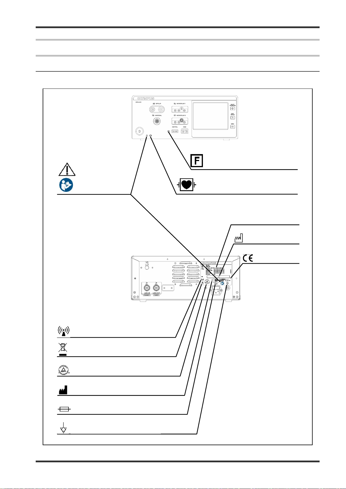
Date of
manufacture
CE marking
Non-ionizing electromagnetic radiation
Output insulated from earth
Caution, read
Defibrillation proof type CF applied
Waste electrical and electronic
equipment
cTUVus marking
Manufacturer
Potential equalization terminal
Fuse rating
Type plate
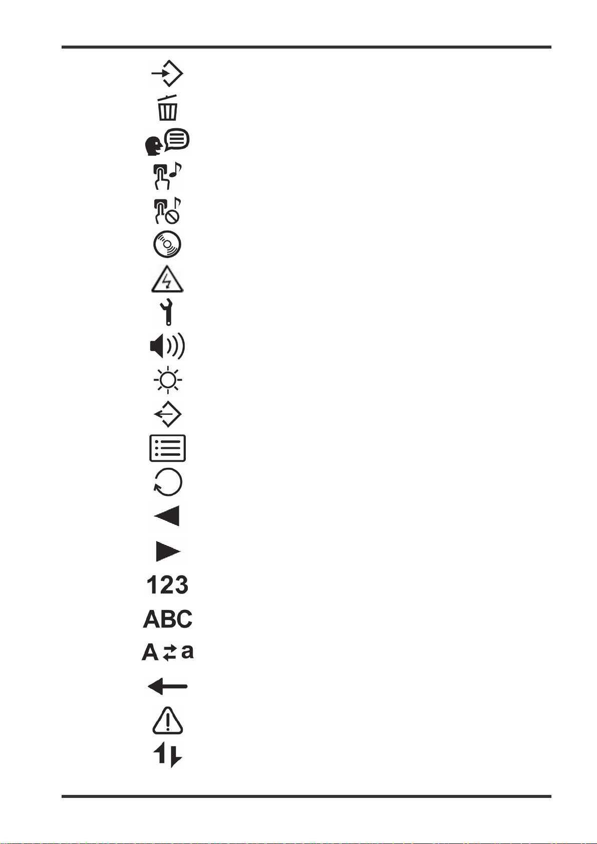
5 Name and Function of each part
5-1 Symbols and descriptions
5-1-1 Safety related symbols
instructions
Refer to
instructions
(connection for neutral electrode)
part (cardiac application)
7.022.211 / ISSUE 5 18 / 110 Chapter 1: PRODUCT SPECIFICATIONs
Page 19
ESG-400
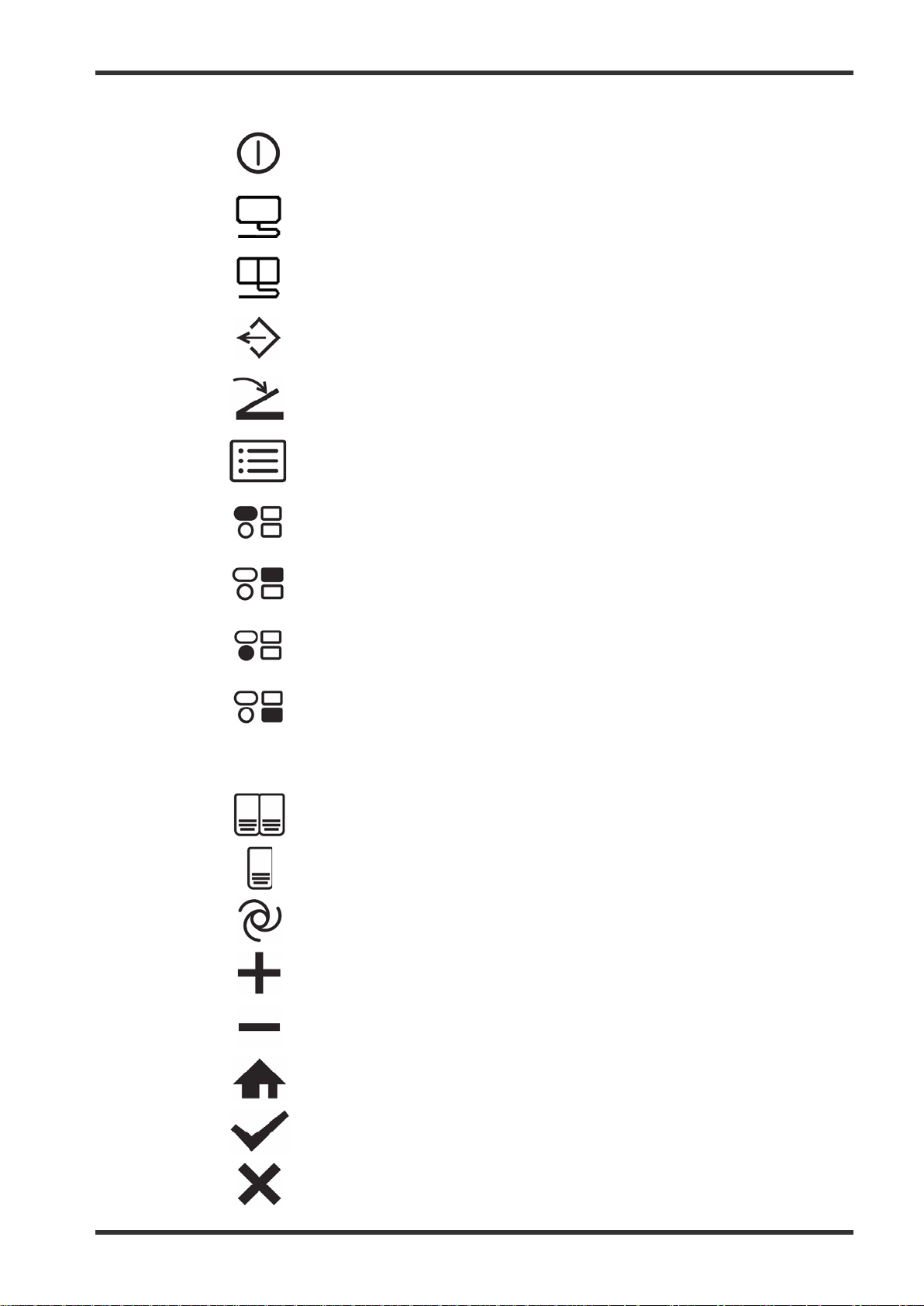
5-1-2 Front panel
Power on / off
Neutral electrode – non-split type
Neutral electrode – split type
Select procedure
Footswitch
Menu
5-1-3 Touch screen
BIPOLAR socket
MONOPOLAR 1 socket
UNIVERSAL socket
MONOPOLAR 2 socket
Double footswitch
Single footswitch
Autostart
Plus
Minus
Return
OK
Cancel
7.022.211 / ISSUE 5 19 / 110 Chapter 1: PRODUCT SPECIFICATIONs
Page 20
ESG-400
Save procedure
Delete procedure
Languages
Touch tone on
Touch tone off
Software version
Safety test
Service
Volume
Brightness
Select procedure (in title line)
Menu (in title line)
Toggle
Previous
Next
Numeric
Alphabetic
7.022.211 / ISSUE 5 20 / 110 Chapter 1: PRODUCT SPECIFICATIONs
Uppercase / lowercase
Backspace
Caution
Communication indicator
Page 21
ESG-400
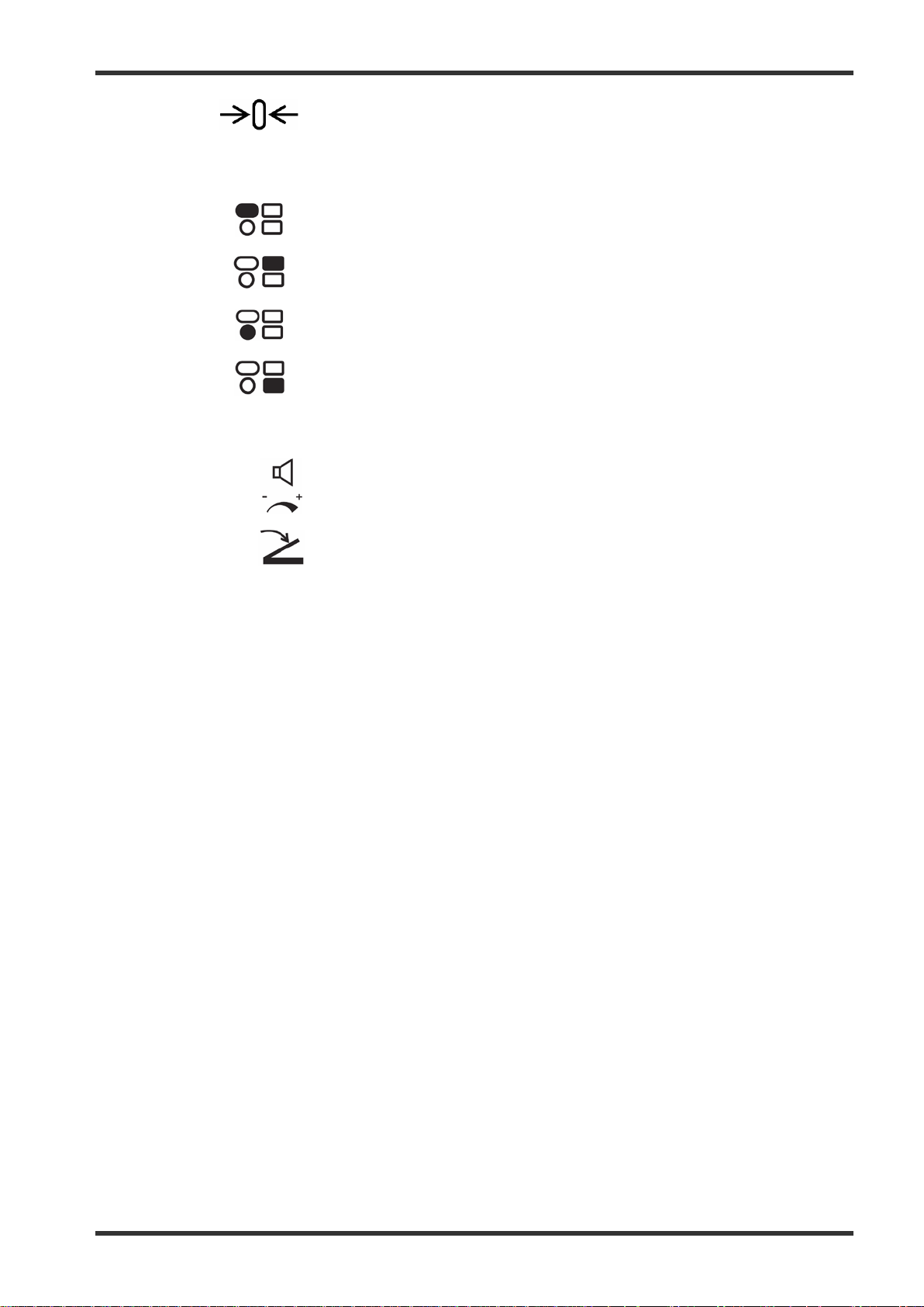
5-1-4 Rear panel
RCAP
Reset
Resistance Controlled Automatic Power
Reference to BIPOLAR socket
Reference to MONOPOLAR 1 socket
Reference to UNIVERSAL socket
Reference to MONOPOLAR 2 socket
Volume
Footswitch
LINK-IN
LINK-OUT
LINK-IN socket
LINK-OUT socket
7.022.211 / ISSUE 5 21 / 110 Chapter 1: PRODUCT SPECIFICATIONs
Page 22
ESG-400
. It is also used to show and m odify the output settings (e.g. mode, output power, effect) as
This button is used to open the “Footswitch screen” to assign one or two footswitch(es) or the autostart
This button is used to open the “Menu screen” to control several functions (save or delete a procedure,
8.
6.
1.
2.
3.
4.
7.
12.
11.
10.
9.
5.
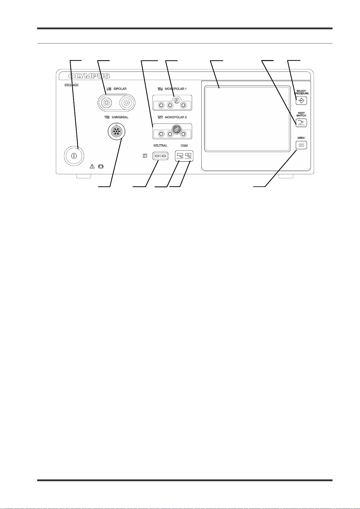
5-2 Front panel
Power sw itch
1.
This switch turns the electrosurgical generator on and off.
BIPOLAR socket
2.
This socket connects the plug of a bipolar HF instrument (applied part).
MONOPOLAR 2 socket
3.
This socket connects the plug of a monopolar HF instrument ( appl ied p art) .
MONOPOLAR 1 socket
4.
This socket connects the plug of a monopolar HF instrument (applied part).
Touch-screen
5.
Displays the connection status of the accessories and peripherals connected to the electrosurgical
generator
well as to control other functions (e.g. save procedures, delete procedures).
FOOTSWITCH push button
6.
function to a specific output socket.
SELECT PROCEDURE push button
7.
This button is used to open the “Selec t Procedure screen” to recall saved settings.
MENU push button
8.
control the touch tone, output volume and brightness as well as other functions).
7.022.211 / ISSUE 5 22 / 110 Chapter 1: PRODUCT SPECIFICATIONs
Page 23

ESG-400
This indicator illuminates green if a split neutral electrode is connected and the contact resistance is
red if the split neutral electrode is not connected
or not applied properly (e.g. bad contact quality or partly dislocated) or no neutral electrode is
Contact quality monitor indicator for split neutral electrode
9.
within an acceptable range. The indicator illuminates
connected (in both cases the activation of monopolar output is disabled).
Contact quality monitor indicator for non-split neut ral electrode
10.
This indicator illuminates green if a non-sp lit neutral electrode is connected.
Neutral electrode socket
11.
This socket connects the plug of a neutral electrode for monopolar application (applied part).
UNIVERSAL socket
12.
This socket connects the plug of an Olympus HF instrument with HF instrument recognition (applied
part).
7.022.211 / ISSUE 5 23 / 110 Chapter 1: PRODUCT SPECIFICATIONs
Page 24
ESG-400
Holes for air ventilation via a cooling fan; there are also ventilation holes on each side of the
oint is used for potential equalization. All equipment hous ings that
screen messages may depend on the
For a detailed explanation of the different types of
chapter 6 “Connection of neutral
electrode” and chapter 3.7 “Connection of HF
1.
2.
3.
4.
7.
6.
5.
1.
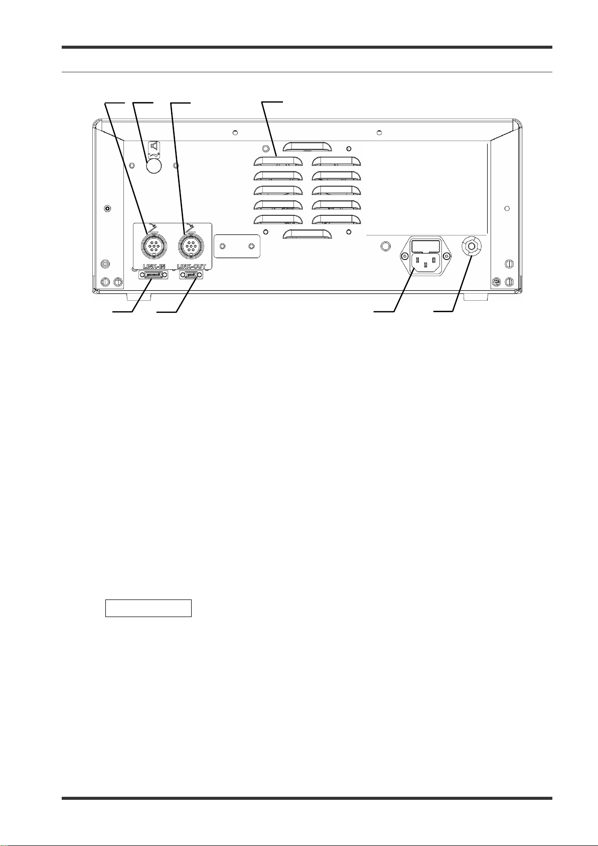
5-3 Rear panel
Footswitch socket s
1.
This socket connects the
Volume control
2.
This knob is used for adjusting the output volume.
Ventilation hole
3.
plug of a single or double pedal footswitch.
electrosurgical generator.
Equipotential bonding point
4.
To increase electrical safety, this p
come into contact with the patient are electrically connected in order to prevent low-frequency
electrical currents from endangering the patient in the event of a defect in the conventi onal protective
conductor system.
AC power socket
5.
This socket serves as a connection to the mains power supply via a power cord
LINK-OUT socket
6.
This socket connects the plug (14-pin) of a cable connected to peripheral equipment.
LINK-IN socket
7.
This socket connects the plug (26-pin) of a cable connected to peripheral equipment.
NOTE
The touch-
language setting of the electrosurgical generator.
sockets, refer to
instruments”.
7.022.211 / ISSUE 5 24 / 110 Chapter 1: PRODUCT SPECIFICATIONs
Page 25
ESG-400
12.
This indicator shows the corresponding output socket where the same symbol is printed on the front
This symbol indicates if the autostart function is assigned to the corresponding output socket. Blank if
1.
1.
2.
3.
4.
5.
8.
6.
11.
7.
9.
10.
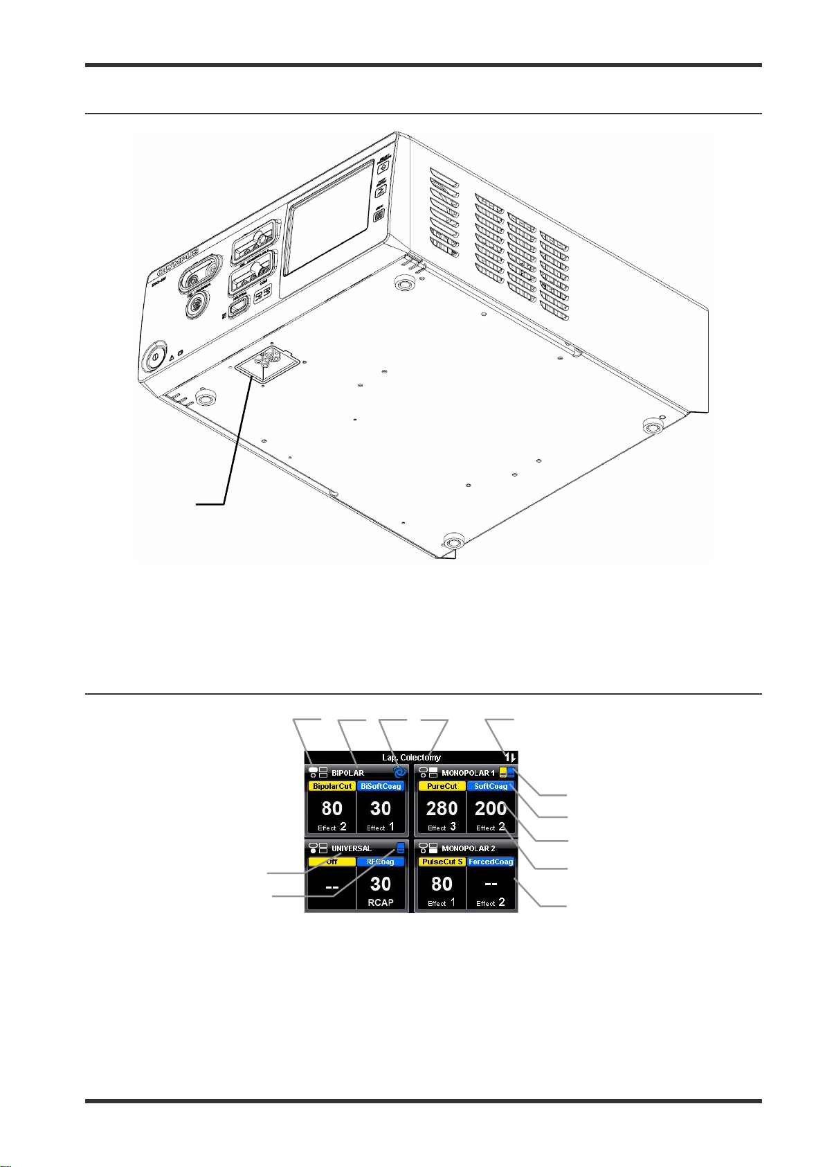
5-4 Bottom panel
Docking socket
1.
This socket connects the plug (7-pin) of a docking connector to connect peripheral equipment. For
more details, see chapter 1-6-1.
5-5 All screen
Reference to output sockets indicator
1.
panel.
Output socket name
2.
The name of the corresponding output socket is displ ay ed here.
Autostart indicator
3.
7.022.211 / ISSUE 5 25 / 110 Chapter 1: PRODUCT SPECIFICATIONs
Page 26
ESG-400
autostart or foots witch is not assigned. Refer to chapter 6.4, “Assign footswitch and autostart function”.
This symbol indicates if communication with peripheral equipment connected to the docking socket is
This symbol indicates if a connected double pedal footswitch is assigned to the corresponding output
socket. Blank if autostart or footswitch is not assigned. Refer to chapter 6.4, “Assign footswitch and
The name of the output mode as selected in the “Mode sc reen” is displayed here. If “Off” is selected,
The number shows the effect as selected in the “Set screen”. For RFCoag mode the RCAP function
Each button covers the entire area including all output socket related information as described above
(3. to 10.). Press the button, to switch to the corresponding “Set screen” to select the mode, power
This symbol indicates if a c onnected single pedal footswitch is assigned to the corresponding output
The name of the instrument or cable will be displayed instead of the output socket name
The name of the output mode as selected in the “Mode screen” is displayed here. Press this button to
1.
5.
2.
2
6.
3.
4.
Procedure name
4.
The name of the selected procedure is displayed here. Blank if no procedure is selected.
Communication indicator
5.
established.
Footswitch indicator (double pedal)
6.
autostart function”.
Output mode
7.
“--“ will be displayed instead of power level and effect.
Output power level
8.
The number shows the output power level as selected in the “Set screen”. If an output power level is
set to zero, “--” will be displayed instead of numbers.
Effect
9.
can be selected instead of an effect (refer to chapter 5.3, “O utput sett ing” ) .
Button area
10.
levels and effects for the corresponding output socket.
Footswitch indicator (single pedal)
11.
socket. Blank if autostart or footswitch is not assigned. Refer to chapter 6.4, “Assign footswitch and
autostart function”.
UNIVERSAL / Instrument name
12.
“UNIVERSAL” if an instrument or cable with instrument recognition is connected to the UNIVERSAL
socket.
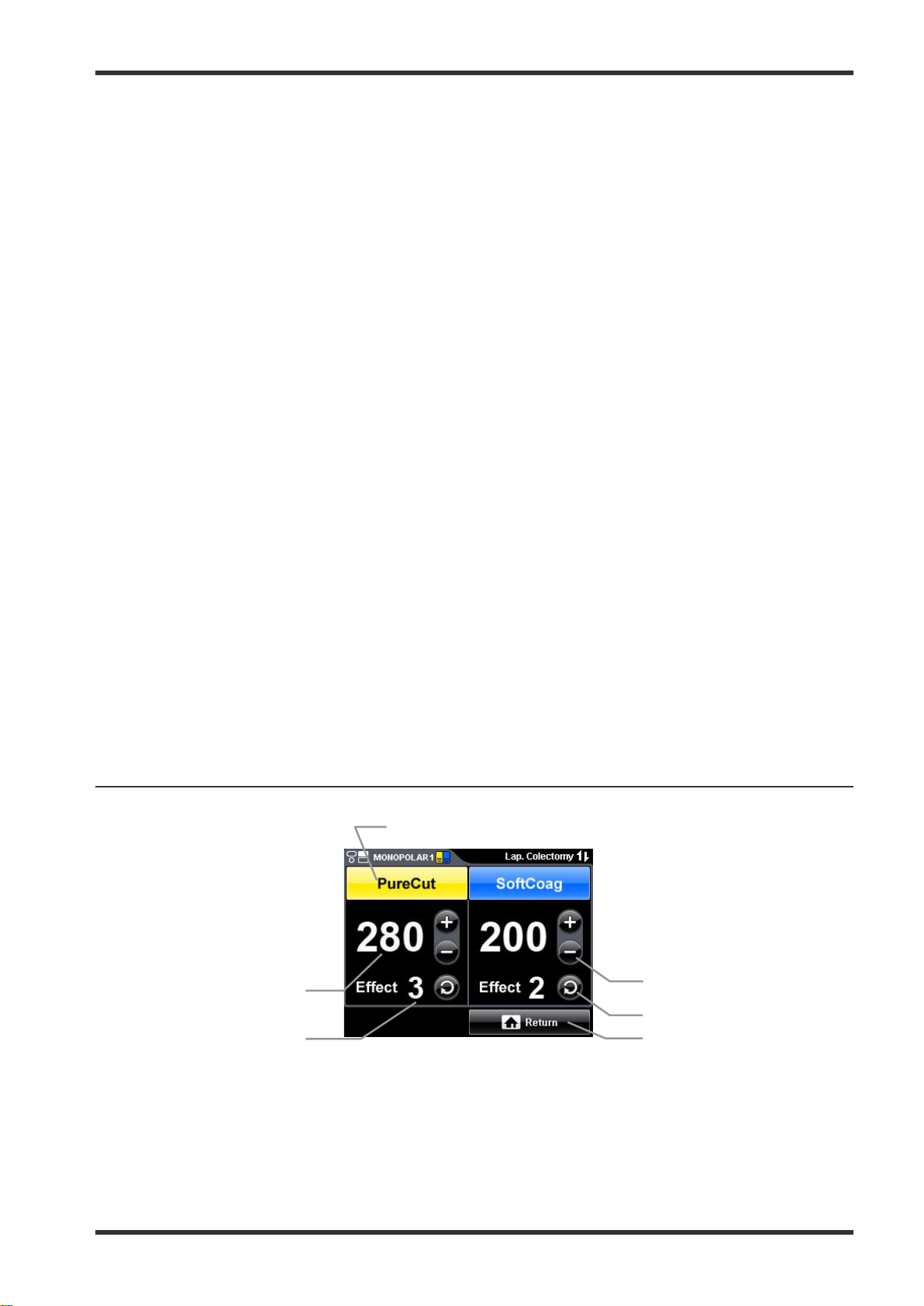
5-6 Set screen
Mode button
1.
switch to the “Mode screen”. If “Off” is selected,
“--“ will be displayed instead of power level and effect.
Plus button / Minus button
2.
These buttons increase / decrease the output power level.
7.022.211 / ISSUE 5 26 / 110 Chapter 1: PRODUCT SPECIFICATIONs
Page 27
ESG-400
The number shows the selected effect. For RFCoag mode the RCAP function can be selected instead
These buttons allow the mode selection for a corresponding output socket as shown in the title line. If
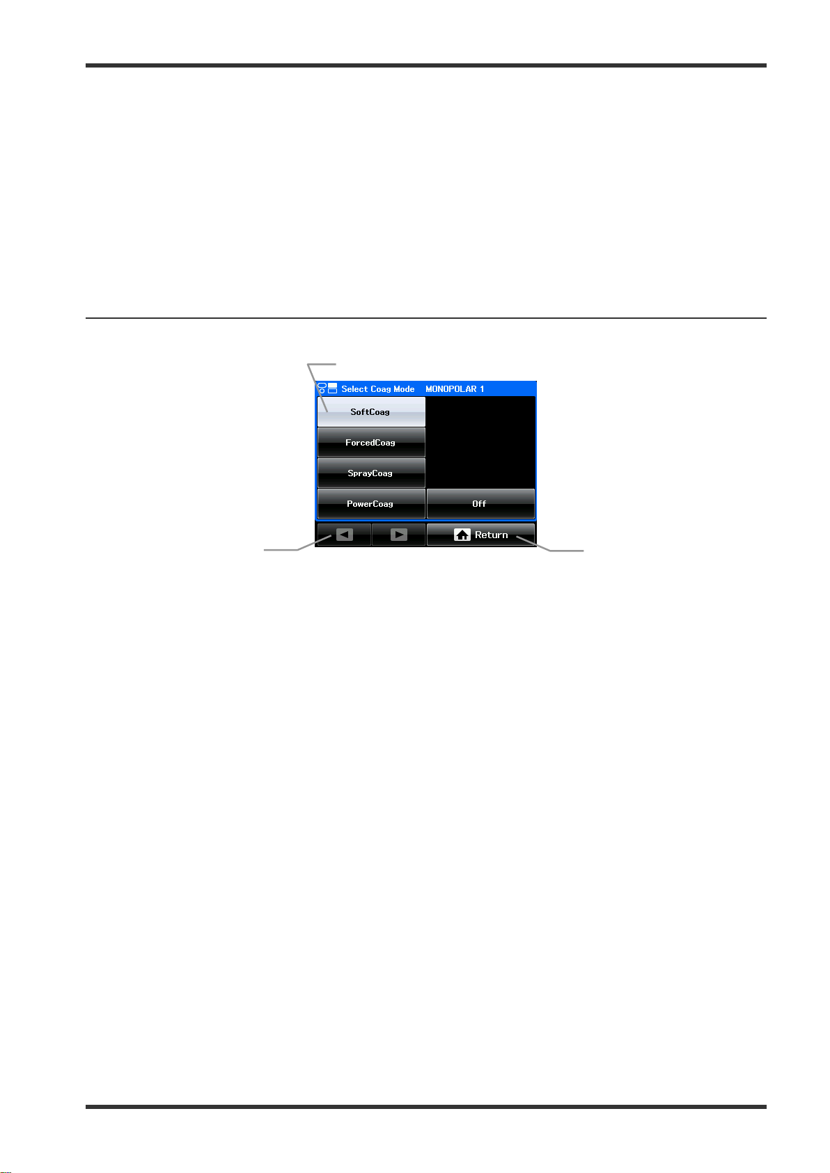
Arrow button
Optional buttons to browse through the mode list. They are disabled if the number of available modes
1.
2.
3.
Toggle button
3.
This button switches to the next effect.
Return button
4.
Press this button to save the settings and to return to the “All screen.”
Output power level
5.
The number shows the selected output power level. If an output power level is set to zero, “--” will be
displayed instead of numbers.
Effect
6.
of an effect (refer to chapter 5.3, “Output setting”)
5-7 Mode screen
Mode button
1.
a selection is already activated, this is indicated by a gray button. If no mode shall be selected, press
the “Off button.”
Return button
2.
Press this button to return to the “Set screen.”
3.
fit to one screen.
7.022.211 / ISSUE 5 27 / 110 Chapter 1: PRODUCT SPECIFICATIONs
Page 28
ESG-400
1.
2.
3.
1.
2.
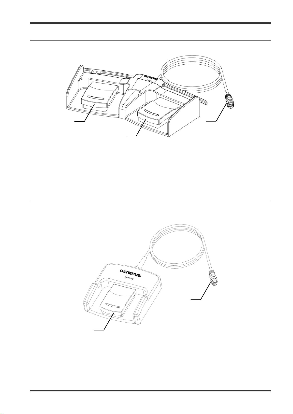
5-8 Footswitch with two pedals
The footswitch with two pedals (Olympus REF: WB50402W) is included in deliv ery .
Cut pedal (yellow color)
1.
This pedal is used to activate the selected cutting mode.
Coagulation pedal (blue color)
2.
This pedal is used to activate the selected coagulation mode.
Footswitch plug
3.
Connects the footswitch with the electrosurgical generator on the rear panel.
5-9 Footswitch with one pedal (optional)
The footswitch with one pedal (Olympus REF: WB50403W) is an optional item which may be purchased
separately.
Coagulation pedal (blue color)
1.
This pedal is used to activate the selected coagulation mode.
Footswitch plug
2.
Connects the footswitch with the electrosurgical generator on the rear panel.
7.022.211 / ISSUE 5 28 / 110 Chapter 1: PRODUCT SPECIFICATIONs
Page 29
ESG-400
3.
Plug on the electrosurgical generator side
1.
2.
3.
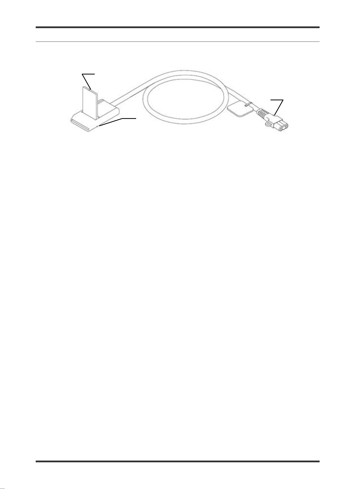
5-10 Neutral electrode cable “P-cord” (optional)
The neutral electrode cable “P-cord” (Olympus REF: MAJ-814) is an optional item for the connection with a
neutral electrode which may be purchased separately.
Lever-locking arm
1.
This arm secures the connector of the neutral electrode with the clamp.
Clamp
2.
This clamp connects the neutral electrode to the “P-cord”.
This plug connects the “P-cord” to the electrosurgical generator.
7.022.211 / ISSUE 5 29 / 110 Chapter 1: PRODUCT SPECIFICATIONs
Page 30
ESG-400
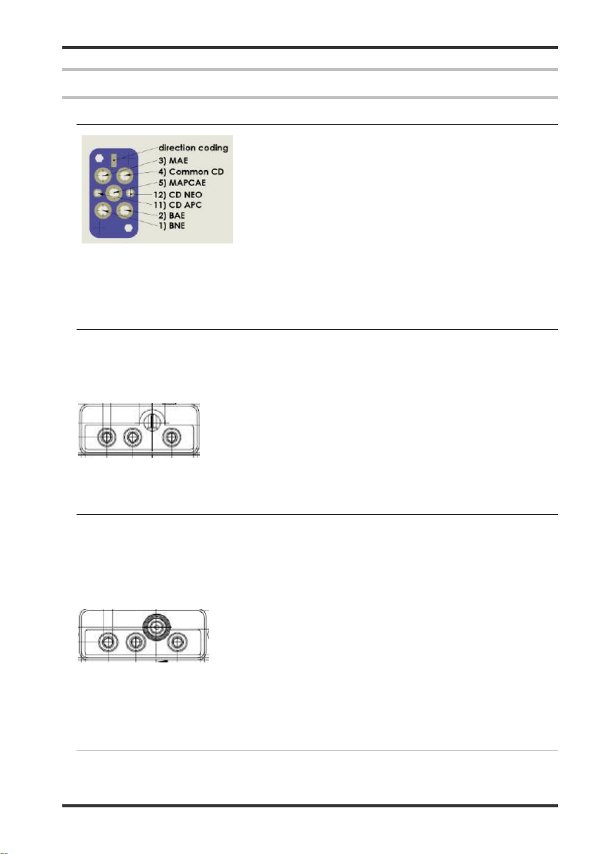
Pinning of connector 13 Docking
Connector
(bottom view) of ESG
1
2 4 3
1 Hand Cut
2 H
3 Active electrode
4 Active electrode
1 Hand Cut
2 Hand Coag
3 Active electrode
4 Cut+Coag+Active electrode (top)
1 2 3
4
6 Connector
6-1 Docking Connector
1) BNE – Bipolar Neutral Electrode
2) BAE – Bipolar Active Electrode
3) MAE – Monopolar Active Electrode
4) Common CD – Common ground for connection detection
5) MAPCAE – Monopolar Activ e Electrode
11) CD APC – Active pin for connection detection
12) CD NEO – Active pin for connection detection
- view of connector side
-400
6-2 Monopolar Standard 1
Type: 3 pin Valleylab, pin diameter = 4mm
1 pin BOVIE, pin diameter = 8 mm
Function: Monopolar output
Finger switch input (only for Valleylab: c ut and coag)
6-3 Monoploar Standard 2 (Erbe)
Type: 3 pin Valleylab, pin diameter = 4mm
Coaxial ERBE, pin diameter = 5 mm (inner) and 9 mm (outer)
Function: Monopolar output
Finger switch input (cut and coag)
6-4 Bipolar Standard 3
Type: 2 pin socket, pin diameter = 4mm / pin distance 28.8 mm
Coaxial socket, pin diameter = 4 mm (inner) and 8 mm (outer)
7.022.211 / ISSUE 5 30 / 110 Chapter 1: PRODUCT SPECIFICATIONs
and Coag
Page 31

ESG-400
1 Neutral electrode
2 Active and neutral electrode
1
2
Pin 3
Pin 2
Pin 4
Pin 5
Pin 6
Pin 1
B (COAG)
A (CUT)
(coding)
Pin 7 - NC
(coding)
Com
Function: Bipolar output
6-5 Monopolar Neutral Electrode
Type: 2 pins socket, Pin diameter = 2.5 mm, Pin distance = 10 mm
Function: Monopolar output
CQM input
Principle sketch of connector 5 Neutral Elec trode
6-6 Foot switch 1 (SIP/SOP)
Type: Foot switch, 7-pol.
Pinning of foot switch connector
7.022.211 / ISSUE 5 31 / 110 Chapter 1: PRODUCT SPECIFICATIONs
Page 32

ESG-400
Left Pedal
Right Pedal
L
Com
L/R
R
M
6-7 Foot switch 2 (SIP/SOP)
Type: Foot switch, 7-pol.
Activation detection of foot switch
7.022.211 / ISSUE 5 32 / 110 Chapter 1: PRODUCT SPECIFICATIONs
Page 33

ESG-400
7 System Diagram
The recommended combinations of ancillary equipment and accessories that can be used with the
electrosurgical generator are listed in the system chart below. In addition, new products released after the
introduction of this product may also become compatible with this electrosurgical generator. For further details,
contact Olympus.
WARNING
7.022.211 / ISSUE 5 33 / 110 Chapter 1: PRODUCT SPECIFICATIONs
Page 34

ESG-400
After cleaning the electrosurgical unit, dry it thoroughly before storage or using
Patient debris and reprocessing chemicals are hazardous. During cleaning
and disinfection, always wear appropriate personal protective equipment, such
perly so that your skin is not exposed. Always
When disconnecting plugs of instruments or power cords, always hold the
Never immerse the electrosurgical unit in water, clean or disinfect by
Do not clean the connectors or the alternating current power inlet. Cleaning
m or corrode the contacts, which could damage the
Do not wipe the external surface with hard or abrasive wiping material. The
The electrosurgical unit m ay be contaminated with infections materials, therefore, before servicing, perform the
following cleaning procedures. For maintenance and storage of other items than those described below, refer to
the respective instructions for use.
8-1 Cleaning
All surfaces of the unit’s housing can be cleaned and disinfected with the cleaning agents and surface
disinfectants normally used for medical equipment (mild cleaning solution, e.g. 70 % isopropyl alcohol). No
liquid must enter the connector or the unit duri ng cleaning.
1) Switch off the electrosurgical unit and disconnect the power cord from the grounded wall outlet.
2) If the equi pm en t and / or accessories are contaminated with blood or other potentially infectious materials,
first wipe off all gross debris using neutral detergent, and then wipe its surface with a lint-free cloth
moistened with a surface disinfectant.
3) To remove dust, dirt and non-patient debris, wipe the electrosurgical unit and footswitch using a soft,
lint-free cloth moistened with 70 % ethyl or isopropyl alcohol.
8 Cleaning, sto rage and disposal
WARNING
CAUTION
it again. If it is used while still wet, there is a risk of electric shock.
as eye wear, face mask, moisture-resistant clothing and chemical-resistant
waterproof gloves that fit pro
remove contaminated protective clothing before leaving the reprocessing area.
plug. Pulling the cable m ay result in damaging of the wires.
immersion, gas sterilization or autoclaving. It may cause equipment damage.
them can defor
electrosurgical unit.
surface will be scratched.
7.022.211 / ISSUE 5 34 / 110 Chapter 1: PRODUCT SPECIFICATIONs
Page 35

ESG-400
Do not store the electrosurgical unit in a location exposed to direct sunlight,
adiation (e.g. near
wave medical treatment
equipment, magnetic resonance imaging equipment, radio or mobile phones).
8-2 Storage
Before storage of the electrosurgical unit, disconnect the power cord and store it properly according to the
environmental conditi on s descr ibed in cha pter 1.4 (Technical dat a).
CAUTION
x-rays, radioactivity, liquids or strong electromagnetic r
microwave medical treatment equipment, short-
Damage to the electrosurgical unit may result.
8-3 Disposal of the unit
When disposing of this electrosurgical unit, or any of its components (such as fuses), follow all applicable
national and local laws and guidelines.
Waste electrical and electronic equipment
In accordance with European Directive 2002/96/EC on waste electrical and elec tronic equipment (WEE E), the
product must not be disposed of as unsorted municipal waste, but s hould be collected separately.
Refer to Olympus for return and / or collection systems available in your country.
7.022.211 / ISSUE 5 35 / 110 Chapter 1: PRODUCT SPECIFICATIONs
Page 36

ESG-400
7.022.211 / ISSUE 5 36 / 110 Chapter 2: Block Description
Page 37

ESG-400
CHAPTER 2: BLOCK DESC RIPTION
1 BLOCK DESCRIPTIONS .............................................................................................. 38
1-1 Motherboard ..................................................................................................................................... 39
1-2 HVPS Board ..................................................................................................................................... 41
1-3 Generator board ............................................................................................................................... 41
1-4 Relay Board ..................................................................................................................................... 41
1-5 Front Panel ....................................................................................................................................... 42
7.022.211 / ISSUE 5 37 / 110 Chapter 2: Block Description
Page 38

ESG-400
Fig. 2.1.1. Block descriptions
1 Block Descriptions
7.022.211 / ISSUE 5 38 / 110 Chapter 2: Block Description
Page 39

ESG-400
1-1 Motherboard
Due to the containing embedded PC the Motherboard is the central unit of the ESG-400. The Motherboard
controls the Relay Board, the HVPS Board and the Generator Board. It contains all input and output interfaces
to the user as well as to other medical devices or computers. Additionally func tionali ties off the board are the
low voltage supplies for the complete unit, the mains input including filters and the measuring part of the
voltage line selection circuit for switching between 115 and 230 VAC.
Overview:
• Embedded PC incl. periphery
• Embedded PC with MPC5200 controller (incl. address and data bus, chip selects,
interrupt inputs, I 2C, SPI, in-/output ports, uarts, timer)
• Watchdog circuit
• Chip select decoder
• Hardware reset
• JTAG interface
• Real time clock
• POF interface for the spark monitor
• Digital input and output circuits
• D/A converters for controlling the HVPS
• A/D converters for measuring different signals from Relay, HVPS and Generator, temperatures and
watching on important voltages
Connections/Interfaces:
• To the PCBs Relay, HVPS and Generator
• Push buttons for user inputs on the front panel
• Volumeboard for changing the speaker volume
• Power Indicator shows power-on of the unit on the front
• CQM Indicator shows status of CQM on the front
• Controlling and driving the main housing fan
• Audio circuit incl. D/A converter and amplifier for sound
• Graphic controller with driver and backlight for the front display
• Touch controller for the touch display
• Ethernet controller and connec tor for external connections
• RS-232 with connector for external connections
• USB host with transceiver and connector for external connections
• FlexRay controller, transceiver and connector for external connections
• Connectors for foots witch incl. detection and analysis circuit
• Connectors for handswitches incl. activation detection circuits
• Instrument recognition circuit for instruments connected to the universal socket
• Detection circuit for devices connec ted to the dock ing co nne c tor
7.022.211 / ISSUE 5 39 / 110 Chapter 2: Block Description
Page 40

ESG-400
Low voltage supplies
• Switching regulators for -12 VDC, +5 VDC and +3,3 VDC (5 V and 3,3 V c ascaded)
• DC/DC converters for isolated +12 VDC and +5 VDC SIP/SOP voltages
• Batteries for a permanent +3 V voltage for RTC and SRAM
• Reference voltage of 8,192 V
Mains input
• Input filters
• Inrush current limiter
• Mains voltage measurement and output signal for a selection circuit on the HVPS
7.022.211 / ISSUE 5 40 / 110 Chapter 2: Block Description
Page 41

ESG-400
1-2 HVPS Board
The high voltage power supply (HVPS) is a switching mode power supply with series resonance circuit. It
provides a high DC voltage for the HF Generator. It contains:
• voltage line selection circuit, f o r automatic change between 110/230 VAC
• simple rectifier circuit
• PWM driving circuit
• driving circuits including a digital flip-flop stage for complete cycle driving
• power FET half-bridge, a series resonance circuit, output transformer and rectifying stage
• current and voltage monitors
• discharge circuit
1-3 Generator board
The Generator Board generates the HF output energy from a DC input voltage and contains:
• control circuit for generating st art and driv in g puls es of “one cy cle” sin us oscil lato r
• driving stage for power FET, parallel resonance circuit and series resonance circuit
• relays for switching between different transformer windings
• HF output voltage monitor and redundant HF voltage monitor
• HF output current monitor and redundant HF current monitor
• HF output phase monitor
• HF leakage current monitor
• spark monitor (SPM) supply circuit
• spark monitor for detecting positive and negative DC voltage offset
1-4 Relay Board
The Relay board is used to connect the active output socket to the generator board. It contains:
• connectors to every single HF output socket
• relays which are separating the non active output terminals from the active output terminals
• separating relays are forced guided relays with read-back contact in secondary circuit to control the relay
status
• contact quality monitor (CQM)
• transient voltage suppression (TVS) diodes in applied part
7.022.211 / ISSUE 5 41 / 110 Chapter 2: Block Description
Page 42

ESG-400
1-5 Front Panel
The Front Panel is the main part of the user interface. It contains:
• LCD touch screen
• Push Buttons
• Contact Quality Monitor
• BIPOLAR socket
• MONOPOLAR 1 socket Valleylab & Bovie
• MONOPOLAR 2 socket Valleylab & Erbe
• UNIVERSAL socket
• Socket for neutral electrode
7.022.211 / ISSUE 5 42 / 110 Chapter 2: Block Description
Page 43

ESG-400
CHAPTER 3: REPAIR SYSTEM
1 ESG-400 MAIN UNIT .................................................................................................... 44
2 BOARD COMPATIBILITY ............................................................................................. 44
3 OPTIONAL A CCESSORIES ......................................................................................... 44
3-1 WB50402W (Footswitch with two pedals) ....................................................................................... 44
3-2 WB50403W (Footswitch with one pedal) ......................................................................................... 44
3-3 MAJ-814 (Neutral electrode cable “P-cord”) .................................................................................... 44
4 PRECAUTIONS ON FUNCTION AND OPERATION SETTINGS ................................. 44
4-1 General Precautions ........................................................................................................................ 44
7.022.211 / ISSUE 5 43 / 110 Chapter 3: Repair System
Page 44

ESG-400
1 ESG-400 Main Unit
(1) In general, the main unit mus t be shipped to a service center in the event of a malfunction.
(2) Indiv id ual units can be replaced.
2 Board Compatibility
The compatibility of boards and components is dependent on the hardware version of the generator. The
hardware version can be indentified by the serial number of the generator.
The serial number starting with 5 numbers, hardware version with WXX and followed by 3 numbers after the
hyphen.
Example: XXXXXWYY-ZZZ, WYY will show the hardware version.
3 Optional Accessories
3-1 WB50402W (Footswitch with two pedals)
Supplied as a spare part subject to repair services in the event of a malfunction.
3-2 WB50403W (Footswitch with one pedal)
Supplied as a spare part subject to repair services in the event of a malfunction.
3-3 MAJ-814 (Neutral electrode cable “P-cord”)
Supplied as a spare part subject to repair services in the event of a malfunction.
4 Precautions on Function and Operation Settings
4-1 General Precautions
Before repair, it is generally advisable to record the function and operation settings as the basis for restoring
these settings after service.
If the original settings cannot be known due to mechanical problems present at the time the unit was accepted
for repair, apply the f actory-set values or the safest settings (such as the lowest output levels). In this case,
inform the user that the settings have been changed.
7.022.211 / ISSUE 5 44 / 110 Chapter 3: Repair System
Page 45

ESG-400
CHAPTER 4: TROUBLESHOOTING
1 GENERAL ..................................................................................................................... 46
2 NEUTRAL ELECTRODE OPERATION ........................................................................ 47
3 ERROR SCREEN, CODES AND MEASURES ............................................................. 48
3-1 What to do when no error code is displayed .................................................................................... 50
3-2 What to do when an error code is displayed .................................................................................... 54
7.022.211 / ISSUE 5 45 / 110 Chapter 4: Troubleshooting
Page 46

ESG-400
1 General
If the electrosurgical unit has visible damage, do not use the electrosurgical unit and contact the legal
manufacturer. If the unit is not functioning properly, use the information in this chapter to identify and correct the
malfunction. If the problem cannot be resolved by the described remedial action, stop using the electrosurgical
unit and contact the legal manufacturer for repair.
DANGER
CAUTION
CAUTION
Never use the electrosurgical unit if an abnorm ali ty is suspected.
Repairs must only be carried out by Olympus or a firm authorized by Olympus.
Preventive maintenance (inspection / periodic safety check) must only be
carried out by a qualified person / technician.
7.022.211 / ISSUE 5 46 / 110 Chapter 4: Troubleshooting
Page 47

ESG-400
2 Neutral electrode operation
Check the following table, to identify or correct failures regarding the neutral elec trode operation.
Contact quality monitor Mode Indication
Bipolar application Standby and activation
Monopolar application
A non-spli t neutral electrode is
connected. Activation is possible.
Contact quality monitor detects
connection of neutral elec trode.
If a split neutral electrode is
connected, it has a short circuit.
Immediately replace the neutral
electrode!
A split neutral electrode is connected.
Activation is possible. Contact quality
monitor detects connectio n of neutral
electrode and contac t to patients’ skin.
During standby: A split or a non-split
neutral electrode is not connected or a
split neutral electrode detaches.
Activation is disabled.
During activation: A split or a non-split
neutral electrode has disconnected or a
split neutral electrode detaches. The
activation is stopped.
A neutral electrode is not required. Contact
quality monitor indicator for split neutral
electrode illuminates red.
Contact quality monitor indicator for non-split
neutral electrode illuminates green.
Contact quality monitor indicator for split
neutral electrode illuminates green.
Contact quality monitor indicator for split
neutral electrode illuminates red.
During activation an alarm signal can be
heard and the touch-screen will display an
error window (E202).
Legend: Red illumination of the indicator
Green illumination of the indic ator
7.022.211 / ISSUE 5 47 / 110 Chapter 4: Troubleshooting
Page 48

ESG-400
tton is not available in software version lower
Error window
Fig. 4.3.1. Error Screen
Error title
Error code
Remedial actions
Caution symbol
3 Error screen, co des and measures
Follow the troubleshooting advices in this chapter, to identify or correct failures. The error window is configured
as shown in figure below.
(Example: E002 Short circuit)
NOTE
If an error occurs (see Fig. 4.3.1):
An error window will appear and an alarm signal is audible.
The OK bu
than 4.00-A
A short message with the error code, error title and a description of the remedial action will be displayed.
The error code consists of an error number shown under the “caution” symbol.
Depending on the error priority, the condition of the audible signal and the “caution” symbol are different
(see Table 4.1).
Proceed with the described remedial action.
The error window disappears after a few seconds, if the error is cleared.
If the error window is still displayed, the error is not cleared. Proceed with the next remedial action if
available.
Error category Error condition priority Indicator (“caution”)
symbol condition
High priority Immediate user response
is required
Medium priority Prompt user response
is required
Low priority Awareness of the user
is required
Table 4.1: Error priorities and the corresponding indicator symbol condition
Flashes in red color
Flashes in yellow color
Constant on in yellow color
7.022.211 / ISSUE 5 48 / 110 Chapter 4: Troubleshooting
Page 49

ESG-400
The electrosurgical generator is equipped with an intelligent
multiple variables. Depending on the risk potential, alarms are
classified in “high priority”, “medium priority” and “low priority”
alarms. An alarm of higher priority overrides an existing alarm of
er priority. If more than one alarm situation of equal priority is
NOTE
alarm system which determines alarm conditions on the base of
low
determined, the one that occurred first is displayed only. This
electrosurgical generator complies with the IEC 60601-1-8: 2006.
7.022.211 / ISSUE 5 49 / 110 Chapter 4: Troubleshooting
Page 50

ESG-400
3-1 What to do when no error code is displayed
Perform the indicated remedial actions below. If the problem cannot be resolved by the described remedial
action, contact the legal manuf actur er.
Situation Possible cause Remedial action
The electrosurgical
generator does not
respond after
pressing the power
switch.
The touch-screen
remains dark after
switching the
electrosurgical
generator on (sound
is audible after
switching on).
The touch-screen
cannot be controlled.
Improper connection of the power cord to
the AC power socket on the rear panel of
the electrosurgical generator or to the
grounded wall outlet.
The grounded wall outlet has wrong or
not output voltage.
The power cord is damaged. Check the power cord for damages and, if
Malfunction of the electrosurgical
generator.
Malfunction of the touch-screen. Contact the legal manufacturer.
An object is in contact with the
touch-screen.
The touch-screen is not properly
calibrated.
Check the power cord and the grounded wall
outlet for correct connection.
Check the grounded wall outlet or use an
alternative grounded wall outlet.
necessary, replace the power cord.
Contact the legal manufacturer.
Remove the object.
Contact the legal manufactur e r.
The electrosurgical
generator does not
react when a push
button on the front
panel is pressed
during standby.
The electrosurgical
generator does not
react when a (push)
button on the front
panel is pressed
during activation.
Malfunction of the touch-screen. Stop using the electrosurgical generator a nd
press the power switch to turn off the
electrosurgical generator. Contact the legal
manufacturer.
A push button is already pressed. Release the push button.
Malfunction of the electrosurgical
generator.
The (push) buttons are not available
during activation.
Contact the legal manufactur e r.
Release the footswitch or hand switch to stop
the activation.
7.022.211 / ISSUE 5 50 / 110 Chapter 4: Troubleshooting
Page 51

ESG-400
Situation Possible cause Remedial action
No sound is audible
during activation.
The volume can not
be adjusted via the
volume control within
the “Menu screen” or
at the rear panel.
The electrosurgical
generator does not
respond to footswitch
or handswitch
activation.
The volume is set to an inaudible level
(e.g. due to high environmental noise).
Malfunction of the electrosurgical
generator.
The volume of the error-related audible
signal is not adjustable.
Malfunction of the electrosurgical
generator.
Improper connection of the footswitch to
one of the footswitch sockets on the rear
panel of the electrosurgical generator or
the HF instrument to the output socket.
The footswitch or the handswitch of the
HF instrument and / or the connection
cable are damaged.
Increase the volume either on the touch-screen
within the “Menu screen” or use the volume
control on the rear panel of the electrosurgical
generator.
Stop using the electr o surg ica l gener at or and
press the power switch to turn off the
electrosurgical generator. Contact the legal
manufacturer.
No action required.
Contact the legal manufactur e r.
Check the footswitch and the HF instrum ent f or
correct connection.
Check the footswitch or the handswitch of the
HF instrument and / or the connection cable for
damages and, if necessary, replace the
footswitch, the HF instrument or the connection
cable.
The incorrect footswitch peda l or
handswitch button is pressed.
The electrosurgical generator is not
switched on.
Another footswitch pedal or handswitch
button of the HF instrument is pressed.
The output is activated by the peripheral
equipment.
A window is displayed on the
touch-screen.
The “All screen” or “Set screen is not
displayed on the touch-screen.
The corresponding output mode has
been deactivated in the “Mode screen”
(“Off” is displayed) or the power level has
been set to “--“.
Press the correct footswitch pedal or
handswitch button of the HF instrument.
Switch on the electrosurgical generator with the
power switch.
To activate the intended output, release the
current pressed footswitch pedal or handswitch
button of the HF instrument.
If the output of the peripheral equipment is
activated, the output of the electrosurgical
generator cannot be activated simultaneously.
Stop using the peri phera l equipment.
Press the “OK button” or “Cancel button” to
close the window or wait until the window
disappears automatically after a few seconds.
Return to the “All screen” or “Set screen”.
Select an output mode in the “Mode screen” or
increase the power level via the “Set screen”
(refer to chapter 5.3, “Output setting”).
Malfunction of the electrosurgical
generator.
If the autostart
function is selected,
the electrosurgical
7.022.211 / ISSUE 5 51 / 110 Chapter 4: Troubleshooting
The autostart function is assigned to
another output socket.
Contact the legal manufactur e r.
Check the correct assignment of the autostart
function (refer to chapter 6.4, “Assign foot switch
and autostart function”).
Page 52

ESG-400
generator does not
Situation Possible cause Remedial action
activate the output
when the electrode
has contact with the
tissue.
If an HF instrument is
connected to the
UNIVERSAL socket,
the electrosurgical
generator does not
recognize the
connected HF
instrument.
Footswitch or
handswitch of the HF
instrument is pressed
and activation sound
is audible but no
output power is
delivered.
Long time delay of the autostart function
has been selected in the “Autostart
screen”.
Malfunction of the electrosurgical
generator.
Improper connection of the Olympus HF
instrument plug with the UNIVERSAL
socket on the front panel of the
electrosurgical generator.
The HF instrument does not support
Olympus HF instrument recognition.
The Olympus HF instrument and / or the
connection cable is damaged.
Malfunction of the electrosurgical
generator.
The footswitch is ass igned to another
output socket.
Improper connection of the HF
instrument plug with the output socket on
the front panel of the electrosurgical
generator.
Set a shorter time delay in the “Autostart
screen” (refer to chapter 6.5, “Menu - Autostart
setup”).
Contact the legal manufactur e r.
Check the Olympus HF instrument plug for
correct connection.
Confirm the use of an Olympus HF instrument
with HF instrument recognition capabilities.
Replace the Olympus HF instrument and / or
the connection cable.
Contact the legal manufactur e r.
Check the correct assignment of the foot sw itch
(refer to chapter 6.4, “Assign footswitch and
autostart function”).
Check the HF instrument plug for correct
connection.
Malfunction of the electrosurgical
generator.
Contact the legal manufactur e r.
7.022.211 / ISSUE 5 52 / 110 Chapter 4: Troubleshooting
Page 53

ESG-400
Situation Possible cause Remedial action
No output power is
delivered when
RFCoag mode with or
without RCAP is
selected and end of
activation signal is
audible.
The output of the
electrosurgical
generator cannot be
deactivated.
The electrosurgical
generator cannot be
switched off.
The electrode has no contact with the
tissue.
Improper connection of the HF
instrument plug with the output socket on
the front panel of the electrosurgical
generator.
Damaged HF instrument connecti on
cable.
Malfunction of the electrosurgical
generator.
The autostart function is selected to the
current used output sock et and both
electrodes touch the tis sue.
Malfunction of the footswitch or
handswitch.
Malfunction of the electrosurgical
generator.
Malfunction of the electrosurgical
generator.
Check that the electrode has contact with the
tissue.
Check the HF instrument plug for correct
connection.
Replace the HF instrument connection cable.
Contact the legal manufacturer.
Remove the electrode from the tissue.
Immediately switch off the electrosurgical
generator by pressing the power switch.
Replace the footswitch or HF instrument with
handswitch.
Contact the legal manufactur e r.
Disconnect the power cord plug from the AC
power socket on the rear panel of the
electrosurgical generator or from the grounded
wall outlet. Contact the legal manufacturer.
Automatic mist &
smoke evacuation
system/function does
not work.
The settings are erroneous. Correct the settings of the compatib le high flow
insufflation unit.
The communication cable i s not
connected.
The connection of the communication
cable is erroneous.
Compatible high flow insufflation unit
malfunction.
Connect the communication cable. Refer to 3.5,
“Automatic mist & smoke evacuation
system/function (when usi ng the compatible
high flow insufflation unit)”.
Reconnect the communication cable. Refer to
Section 3.5, “Automatic mist & smoke
evacuation system/function (when using the
compatible high flow insufflation unit)”.
Contact Olympus.
7.022.211 / ISSUE 5 53 / 110 Chapter 4: Troubleshooting
Page 54

ESG-400
3-2 What to do when an error code is displayed
If an error code is displayed, perform the indicated remedial actions below. If the problem cannot be resolved by
the described remedial action, contact the legal manufacturer.
The error messages frequently used are translated in table 4.2.
Description in Error Code Table Actual messages displayed on ESG-400
“Auto-restart”
“Contact OLY” If the problem persists, contact Olympus.
“Release FSW”
“Release HSW”
“Replace Instrument”
“Reconnect Instrument”
“Cable Connection”
“Cable Damage”
Table 4.2: frequently used error messages
Error
no.
E001
NOTE
Error message Possible cause Remedial action
Open circuit
Check if the electrodes of
the instrument have
proper tissue contact.
The ESG-400 will be restarted automatic ally when the error with the message
of “Auto-restart” is occurred.
Electrodes of the HF instrument
may have no proper tissue contact.
Malfunction of the HF instrument
and / or the connection cable.
ESG-400 will automatically restart.
Release the footswitch pedal to continue.
Release the handswitch of the instrument to contin ue.
If the problem persists, replace the instrument.
Reconnect the instrument to the UNIVERSAL socket.
Check all communication c ables are connected correctly.
Check all cables for damage. If necessary,
Ensure that the electrodes of the HF
instrument have proper tissue contact.
Replace the HF instrument and / or the
connection cable.
replace the cables.
E002
E003
E004
E006
Short circuit
Ensure the instrument
electrodes do not come
into contact with each
other and proceed.
--Error
„Auto-restart”
„Contact OLY”
Non-conductive fluid
Ensure conductive fluid is
used for bipolar
resection.
Electrodes of the HF instrument
may touch each other.
Malfunction of the HF instrument
and / or the connection cable.
DockingConnectorError --Internal software error. Send back to Olympus Service
Use of non-conductive fluid during a
bipolar cutting procedure.
The active and / or neutral electrode
is within an air environment.
The bipolar Olympus HF instrument
has not been properly connected to
the UNIVERSAL socket or damaged
Ensure that the electrodes of the HF
instrument do not touch each other.
Replace the HF instrument and / or the
connection cable.
Ensure that conductive fluid is used
during bipolar resection procedure.
Always immerse the active and / or
neutral electrode within the conductive
fluid.
Check the connection of the bipolar
Olympus HF instrument to the connection
cable and the connection of the
7.022.211 / ISSUE 5 54 / 110 Chapter 4: Troubleshooting
Page 55

ESG-400
connection cable.
connection cable to the UNIVERSAL
E007
E013
E016
E017
Wrong or broken Footswitch,
E018
E019
E020
E023
E024
Error
no.
[…]
E011
E012
E014
E015
Error message Possible cause Remedial action
socket and / or replace the connection
cable.
Error
„Auto-restart”
„Contact OLY”
Adjustment incomplete
„Contact OLY”
Error
„Auto-restart”
„Contact OLY”
Burn-in incomplete
„Contact OLY”
The electrode might be
contaminated and encrusted.
Adjustment missing or incomplete. Complete the adjustment of the device.
Burn-in missing or incomplete. Complete the burn-in of the dev ice
Check the electrodes for conta minat io n
and encrustation before use and, if
necessary, clean the electrodes.
Refer to E004
Refer to E004
E021
E022
Error
„Contact OLY”
Error
„Auto-restart”
„Contact OLY”
Footswitch
combination
Connection of only one
single pedal and/or only
one double pedal
footswitch is allowed.
„Contact OLY”
Error
„Contact OLY”
Invalid serial number
„Contact OLY”
damaged hardware.
Two single pedal or two double
pedal footswitches have been
connected.
Internal hardware error. Send back to Olympus Service
Wrong or missing serial number of
the device.
1. Check the Footswitch connection.
2. Change the Footswitch.
3. Send back to Olympus Service
Refer to E004
Ensure that only one single pedal and/or
only one double pedal footswitch are
connected.
Send back to factory.
[…]
E030
7.022.211 / ISSUE 5 55 / 110 Chapter 4: Troubleshooting
Error
„Auto-restart”
„Contact OLY”
Refer to E004
Page 56

ESG-400
E031
E032
Wrong docking connector cod i ng
E033
E035
E038
E039
E045
E48
Communication error with USG-400
E049
E052
Communication error with USG-400
Error
no.
E034
E036
E037
Error message Possible cause Remedial action
Error
„Auto-restart”
„Contact OLY”
Error
„Contact OLY”
Error
„Auto-restart”
„Contact OLY”
Error
„Auto-restart”
„Contact OLY”
Error
Wrong docking connector cod i ng
signal, broken hardware.
signal, broken hardware.
Internal hardware error. Send back to Olympus Ser vice
1. Check the docking connection to the
USG-400.
2. Send back to Olympus Service
1. Check the docking connection to the
USG-400.
2. Send back to Olympus Service
Refer to E020
Refer to E004
[…]
E043
[…]
E047
[…]
E051
„Contact OLY”
Error
„Auto-restart”
„Contact OLY”
Error
„Contact OLY”
Error
„Auto-restart”
„Contact OLY”
Error
„Contact OLY”
Refer to E004
Communication error with USG-400
or other devices.
or other devices.
Communication error with USG-400
or other devices.
1. Check the FlexRay connections.
2. Check if all other devices are working
properly.
3. Send back to Olympus Service
1. Check the FlexRay connections.
2. Check if all other devices are working
properly.
3. Send back to Olympus Service
1. Check the FlexRay connections.
2. Check if all other devices are working
properly.
Error
„Auto-restart”
„Contact OLY”
7.022.211 / ISSUE 5 56 / 110 Chapter 4: Troubleshooting
or other devices.
3. Send back to Olympus Service
1. Check the FlexRay connections.
2. Check if all other devices are working
properly.
3. Send back to Olympus Service
Page 57

ESG-400
E053
Communication error with USG-400
E054
1. Check the FlexRay connections.
E055
Communication error with USG-400
E056
1. Check the FlexRay connections.
E058
E061
E062
E063
E067
E068
E074
E078
Error
no.
E057
Error message Possible cause Remedial action
Error
„Contact OLY”
Error
„Auto-restart”
„Contact OLY”
Error
„Contact OLY”
Error
„Auto-restart”
„Contact OLY”
or other devices.
2. Check if all other devices are
working properly.
3. Update the software.
or other devices.
2. Check if all other devices are
working properly.
3. Update the software.
1. Check the FlexRay c onnections.
2. Check if all other devices are working
properly.
3. Send back to Olympus Service
1. Check the FlexRay connections.
2. Check if all other devices are working
properly.
3. Send back to Olympus Service
1. Check the FlexRay connections.
2. Check if all other devices are working
properly.
3. Send back to Olympus Service
1. Check the FlexRay connections.
2. Check if all other devices are working
properly.
3. Send back to Olympus Service
E059
E060
[…]
E066
[…]
E073
E075
Error
„Auto-restart”
„Contact OLY”
Error
„Auto-restart”
„Contact OLY”
Error
„Contact OLY”
Error
„Contact OLY”
Error
„Auto-restart”
„Contact OLY”
Error
„Contact OLY”
Error
„Auto-restart”
Internal software or hardwar e error. Send back to Olympus Service
Refer to E004
Refer to E004
Refer to E004
Refer to E045
Refer to E045
Refer to E045
[…]
7.022.211 / ISSUE 5 57 / 110 Chapter 4: Troubleshooting
„Contact OLY”
Error
Refer to E045
Page 58

ESG-400
E080
E081
E082
E085
Send back to Olympus Service
E100
E102
E103
E104
E105
E106
E107
Error
no.
E083
E084
[…]
E099
E101
Error message Possible cause Remedial action
„Contact OLY”
Error
„Auto-restart”
„Contact OLY”
Error
„Auto-restart”
„Contact OLY”
Error
„Auto-restart”
„Contact OLY”
Error
„Auto-restart”
„Contact OLY”
Error
„Auto-restart”
Internal hardware error.
Spark Monitor communication error. Send back to Olympus Service
Refer to E045
Refer to E004
Refer to E085
„Contact OLY”
Push button pressed
Release the push button
to continue.
„Contact OLY”
Footswitch pedal
pressed
„Release FSW”
„Contact OLY”
Footswitch pedal
pressed
„Release FSW”
„Contact OLY”
Footswitch pedal
pressed
„Release FSW”
„Contact OLY”
A push button on the Front Panel is
pressed while switching on.
A pressed Cut Pedal on Footswitch
1 has been detected during
power-up.
Malfunction of the footswitch. Change the Footswitch 1.
A pressed Coag Pedal on
Footswitch 1 has been detected
during power-up.
Malfunction of the footswitch. Change the Footswitch 1.
A pressed Cut Pedal on Footswitch
2 has been detected during
power-up.
Malfunction of the footswitch. Change the Footswitch 2.
Release the push button.
Release the Cut Pedal on Footswitch 1
and restart the device.
Release the Coag Pedal on Footswitch 1
and restart the device.
Release the Cut Pedal on Footswitch 2
and restart the device.
Footswitch pedal
pressed
„Release FSW”
„Contact OLY”
7.022.211 / ISSUE 5 58 / 110 Chapter 4: Troubleshooting
A pressed Coag Pedal on
Footswitch 2 has been detected
during power-up.
Malfunction of the footswitch. Change the Footswitch 2.
Release the Coag Pedal on Footswitch 2
and restart the device.
Page 59

ESG-400
E108
E109
E110
E111
E112
E113
E114
E115
E116
E120
Error
no.
Error message Possible cause Remedial action
Handswitch pressed
„Release HSW”
„Replace Instrument”
„Contact OLY”
Handswitch pressed
„Release HSW”
„Replace Instrument”
„Contact OLY”
Handswitch pressed
„Release HSW”
„Replace Instrument”
„Contact OLY”
Handswitch pressed
„Release HSW”
„Replace Instrument”
„Contact OLY”
A pressed Cut Handswitch at the
Monopolar 1 socket has been
detected during power-up.
Malfunction of the HF instrument. Replace the HF instrument.
A pressed Coag Handswitch at the
Monopolar 1 socket has been
detected during power-up.
Malfunction of the HF instrument. Replace the HF instrument.
A pressed Cut Handswitch at the
Monopolar 2 socket has been
detected during power-up.
Malfunction of the HF instrument. Replace the HF instrument.
A pressed Coag Handswitch at the
Monopolar 2 socket has been
detected during power-up.
Malfunction of the HF instrument. Replace the HF instrument.
Release the Cut Handswitch at the
Monopolar 1 socket and restart the
device.
Release the Coag Handswitch at the
Monopolar 1 socket and restart the
device.
Release the Cut Handswitch at the
Monopolar 2 socket and restart the
device.
Release the Coag Handswitch at the
Monopolar 2 socket and restart the
device.
Handswitch pressed
„Release HSW”
„Replace Instrument”
„Contact OLY”
Handswitch pressed
„Release HSW”
„Replace Instrument”
„Contact OLY”
Touch-screen pressed
Do not touch the screen.
„Contact OLY”
Application time limit
exceeded
Release the footswitch or
handswitch and
reactivate to continue.
„Contact OLY”
A pressed Cut Handswitch at the
Multifunction socket has been
detected during power-up.
Malfunction of the HF instrument. Replace the HF instrument.
A pressed Coag Handswitch at the
Multifunction socket has been
detected during power-up.
Malfunction of the HF instrument. Replace the HF instrument.
The screen is touched while
switching on.
The maximum time limit for the
application has been exceeded.
Release the Cut Handswitch at the
Multifunction socket and restart the
device.
Release the Coag Handswitch at the
Multifunction socket and restart the
device.
Release the finger from the screen.
Release the footswitch or handswitch for
about 15 sec. and activate again by
repressing the footswitch or handswitch.
[…]
E119
E121
7.022.211 / ISSUE 5 59 / 110 Chapter 4: Troubleshooting
Error
„Auto-restart”
„Contact OLY”
Error
„Contact OLY”
Refer to E004
Refer to E004
Page 60

ESG-400
E122
E131
E132
Internal hardware error.
E133
Internal hardware error.
E134
Internal hardware error.
Send back to Olympus Service
E135
E136
E137
E138
E139
Error
no.
[…]
E130
Error message Possible cause Remedial action
Error
„Auto-restart”
„Contact OLY”
Unknown instrument
„Reconnect Instrument”
„Contact OLY”
Error
„Auto-restart”
„Contact OLY”
Error
„Auto-restart”
„Contact OLY”
Error
An Olympus HF instrument has not
been properly connected to the
UNIVERSAL socket.
Invalid default mode detected at the
instrument connected to the
Multifunction socket.
Refer to E004
Check the connection of the Olympus HF
instrument to the UNIVERSAL socket.
Change the Instrument at the
Multifunction socket
Send back to Olympus Service
Send back to Olympus Service
„Contact OLY”
Single pedal footswitch
not assigned
Single pedal footswitch
not assigned
„Contact OLY”
Double pedal
footswitch not
assigned
Double pedal footswitch
not assigned
„Contact OLY”
Error
„Auto-restart”
„Contact OLY”
Error
„Contact OLY”
The single pedal footswitch has not
been assigned to the corresponding
output socket.
The double pedal footswitch has not
assigned to the corresponding
output socket.
The Auto Start feature is not
assigned correctly.
Invalid Thunder Beat mode sett ing
detected.
Assign the single pedal footswitch.
Assign the double pedal footswitch.
Reassign the Auto Start feature.
1. Check the Thunder Beat instrument
connected to the USG-400.
2. Check the USG-400.
Error
„Contact OLY”
7.022.211 / ISSUE 5 60 / 110 Chapter 4: Troubleshooting
Invalid Thunder Beat seal mode
setting detected.
1. Check the Thunder Beat instrument
connected to the USG-400.
2. Check the USG-400.
Page 61

ESG-400
E140
No mode has been selected while
Select a mode via the “Mode screen”.
E141
E142
E147
E148
E149
E150
E151
E152
Error
no.
[…]
E145
Error message Possible cause Remedial action
No mode selected
No mode selected
Select a mode
„Contact OLY”
Power set to zero (--)
Set a valid power level
„Contact OLY”
Error
„Auto-restart”
„Contact OLY”
Unknown instrument
„Reconnect Instrument”
„Replace Instrument”
„Contact OLY”
activating.
The power level for the c hosen
mode is set to zero.
An Olympus HF instrument has not
been properly connected to the
UNIVERSAL socket.
The instrument connected to the
Multifunction socket can not be
determined.
Increase the power level via the “Set
screen”.
Refer to E004
Check the connection of the Olympus HF
instrument to the UNIVERSAL socket.
Change the connected instrument at the
Multifunction socket,
Unknown instrument
„Reconnect Instrument”
„Replace Instrument”
„Contact OLY”
Unknown instrument
„Reconnect Instrument”
„Replace Instrument”
„Contact OLY”
Error
„Auto-restart”
„Contact OLY”
Unknown instrument
„Reconnect Instrument”
„Replace Instrument”
„Contact OLY”
An Olympus HF instrument has not
been properly connected to the
UNIVERSAL socket.
A short circuit at the Multifunction
socket has been detected.
An Olympus HF instrument has not
been properly connected to the
UNIVERSAL socket.
A malfunc tion at the Multifunction
socket has been detected.
Refer to E004
An Olympus HF instrument has not
been properly connected to the
UNIVERSAL socket.
Invalid power setting detected at the
instrument connected to the
Multifunction socket.
Check the connection of the Olympus HF
instrument to the UNIVERSAL socket.
Change the connected instrum ent at the
Multifunction socket
Check the connection of the Olympus HF
instrument to the UNIVERSAL socket.
Change the connected instrument at the
Multifunction socket
Check the connection of the Olympus HF
instrument to the UNIVERSAL socket.
Change the Instrument at the
Multifunction socket
Unknown instrument
„Reconnect Instrument”
„Replace Instrument”
„Contact OLY”
7.022.211 / ISSUE 5 61 / 110 Chapter 4: Troubleshooting
An Olympus HF instrument has not
been properly connected to the
UNIVERSAL socket.
Invalid effect setting detect ed at the
instrument connected to the
Multifunction socket.
Check the connection of the Olympus HF
instrument to the UNIVERSAL socket.
Change the Instrument at the
Multifunction socket
Page 62

ESG-400
E153
E154
E159
E165
E166
E167
E168
E171
E179
The generator (Generator Board) is
Error
no.
Error message Possible cause Remedial action
Unknown instrument
„Reconnect Instrument”
„Replace Instrument”
„Contact OLY”
Unknown instrument
„Reconnect Instrument”
„Replace Instrument”
„Contact OLY”
Unknown instrument
„Reconnect Instrument”
„Replace Instrument”
„Contact OLY”
An Olympus HF instrument has not
been properly connected to the
UNIVERSAL socket.
Invalid default Cut Mode detected at
the instrument connected to the
Multifunction socket.
An Olympus HF instrument has not
been properly connected to the
UNIVERSAL socket.
Invalid default Coag Mode detected
at the instrument connec ted to the
Multifunction socket.
An Olympus HF instrument has not
been properly connected to the
UNIVERSAL socket.
Invalid Mode detected at the
instrument connected to the
Multifunction socket.
Check the connection of the Olympus HF
instrument to the UNIVERSAL socket.
Change the Instrument at the
Multifunction socket
Check the connection of the Olympus HF
instrument to the UNIVERSAL socket.
Change the Instrument at the
Multifunction socket
Check the connection of the Olympus HF
instrument to the UNIVERSAL socket.
Change the Instrument at the
Multifunction socket
E169
E170
[…]
E178
Error
„Auto-restart”
„Contact OLY”
Unknown instrument
„Reconnect Instrument”
„Replace Instrument”
„Contact OLY”
Unknown instrument
„Reconnect Instrument”
„Replace Instrument”
„Contact OLY”
Error
„Auto-restart”
„Contact OLY”
Error
„Auto-restart”
„Contact OLY”
Refer to E004
An Olympus HF instrument has not
been properly connected to the
UNIVERSAL socket.
Invalid Version Number detected at
the instrument connected to the
Multifunction socket.
An Olympus HF instrument has not
been properly connected to the
UNIVERSAL socket.
Internal software error. Change the Embedded PC, change the
Internal hardware error. Send back to Olympus Service
Check the connection of the Olympus HF
instrument to the UNIVERSAL socket.
Change the Instrument at the
Multifunction socket
Check the connection of the Olympus HF
instrument to the UNIVERSAL socket.
Motherboard
Refer to E004
T emper atur e below
limit
Switch off ESG-400 and
wait until operating
temperature is reached.
7.022.211 / ISSUE 5 62 / 110 Chapter 4: Troubleshooting
„Contact OLY”
too cold.
Switch off the electrosurgica l gener at or
and wait until it has reached the specified
operating temperature.
Page 63

ESG-400
E180
The generator (Generator Board) is
E181
The generator (HVPS Board) is too
E182
The generator (HVPS Board) is too
E183
E186
E187
E188
E189
E197
Error
no.
Error message Possible cause Remedial action
T emper atur e above
limit
Switch off the ESG-400
and wait until it has
cooled down.
„Contact OLY”
Temperature below
limit
Switch off ESG-400 and
wait until operating
temperature is reached.
„Contact OLY”
T emper atur e above
limit
Switch off the ESG-400
and wait until it has
cooled down.
„Contact OLY”
too hot.
cold.
hot.
Switch off the electrosurgica l gener at or
and wait until it has cooled down or
reached the specified operating
temperature.
Switch off the electrosurgica l gener at or
and wait until it has reached the specified
operating temperature.
Switch off the electrosurgica l gener at or
and wait until it has cooled down or
reached the specified operating
temperature.
E184
E185
[…]
E196
E198
Error
„Contact OLY”
Error
„Contact OLY”
Increased HF leakage
current
Check if an instrument,
the neutral electrode or
patient is unintentionally
grounded
„Contact OLY”
Excessive HF leakage
current
Check if an instrument,
the neutral electrode or
patient is unintentionally
grounded
„Contact OLY”
Error
„Contact OLY”
Error
„Auto-restart”
Refer to E132
Internal hardware error. Send back to Olympus Service
The high frequency leakage current
has exceeded the limit of 150 mA
for monopolar application or 100 mA
for bipolar application.
The high frequency leakage current
has exceeded the limit of 300 mA
for monopolar application or 200 mA
for bipolar application.
Check if an instrument, the neutral
electrode or the patient is unintentionally
grounded.
Check if an instrument, the neutral
electrode or the patient is unintentionally
grounded.
Refer to 132
Refer to 132
7.022.211 / ISSUE 5 63 / 110 Chapter 4: Troubleshooting
„Contact OLY”
Page 64

ESG-400
E199
E200
E202
E203
E212
E213
E214
E215
E216
E220
E222
E295
E296
Error
no.
E201
[…]
E211
Error message Possible cause Remedial action
Error
„Contact OLY”
Error
„Contact OLY”
Insufficient neutral
electrode contact
Check the connection
and attachment of the
neutral electrode.
If the problem persists,
attach a new neutral
electrode.
„Contact OLY”
Error
„Auto-restart”
„Contact OLY”
The contact resistance of the
neutral electrode is too high or the
neutral electrode is not connected.
Malfunction of the neutral electrode
and / or the neutral electrode cable.
Refer to 133
Refer to 132
Check the connection / attachment of the
neutral electrode.
Replace the neutral electrode and / or the
cable.
Refer to E020
E217
[…]
E294
Error
„Contact OLY”
Error
„Auto-restart”
„Contact OLY”
Low battery
„Contact OLY”
Error
„Contact OLY”
Error
„Auto-restart”
„Contact OLY”
Error
„Auto-restart”
„Contact OLY”
Error
„Auto-restart”
„Contact OLY”
Refer to E020
Refer to E020
The batteries on the Motherboard
are low and caused a loss of data.
Internal software or hardwar e error. Send back to Olympus Service
Send back to Olympus Service
Refer to E020
Refer to E058
Refer to E058
Error
„Auto-restart”
„Contact OLY”
Error
7.022.211 / ISSUE 5 64 / 110 Chapter 4: Troubleshooting
Unable to read the data at the
Multifunction socket.
Unable to write the data from the 1. Change the connected instrument at
1. Change the connected instrument at
the Multifunction socket.
2. Send back to Olympus Service
Page 65

ESG-400
Multifunction socket.
the Multifunction socket.
E297
E299
E390
E391
E394
E396
E397
Error
no.
[…]
E387
Error message Possible cause Remedial action
„Auto-restart”
„Contact OLY”
Error
„Auto-restart”
„Contact OLY”
Error
„Auto-restart”
„Contact OLY”
Communication error
„Cable Connection”
„Cable Damage”
„Contact OLY”
Unable to read the instrument name
from the Multifunction s ocket.
Improper connection of the
communication cables to the
LINK-OUT / LINK-IN socket: “The
communication to other devices has
been aborted.”
2. Send back to Olympus Service
1. Change the connected instrument at
the Multifunction socket.
2. Send back to Olympus Service
Refer to E058
1. Check all cable connections.
2. Check all other connected devices.
3. Send back to Olympus Service
E392
E393
Error
„Contact OLY”
Communication error
„Cable Connection”
„Cable Damage”
„Contact OLY”
T emper atur e below
limit
Switch off ESG-400 and
wait until operating
temperature is reached.
„Contact OLY”
T emper atur e above
limit
Malfunction or damage of the
communication cables.
Refer to E058
Improper connection of the
communication cables to the
LINK-OUT / LINK-IN socket: “The
ring connection to other devices has
been detected.”
Malfunction or damage of the
communication cables.
The generator (Generator Board) is
too cold.
The generator (Generator Board) is
too hot.
Check the cables for damages and, if
necessary, replace the cables.
1. Check all cable connections.
2. Check all other connected devices.
3. Send back to Olympus Service.
.
Check the cables for damages and, if
necessary, replace the cables.
Place the generator at norm al room
temperature and wait until it is warmed
up before use.
Wait until the generator has cooled down.
7.022.211 / ISSUE 5 65 / 110 Chapter 4: Troub les hoot ing
Switch off the ESG-400
and wait until it has
cooled down.
„Contact OLY”
Page 66

ESG-400
E398
The generator (HVPS Board) is too
Place the generator at normal room
E399
E400
Refer to E058
E409
E410
E411
E412
Refer to E058
Error
no.
[…]
E408
Error message Possible cause Remedial action
T emper atur e below
limit
Switch off ESG-400 and
wait until operating
temperature is reached.
„Contact OLY”
Temperature above
limit
Switch off the ESG-400
and wait until it has
cooled down.
„Contact OLY”
Error
„Auto-restart”
„Contact OLY”
Communication error
„Cable Connection”
„Cable Damage”
„Contact OLY”
cold.
The generator (HVPS Board) is too
hot.
Improper connection of the
communication cables to the
LINK-OUT / LINK-IN socket: “The
communication problem to other
devices has been detected.”
temperature and wait until it is warmed
up before use.
Wait until the generator has cooled down.
1. Check all cable connections.
2. Check all other connected devices.
3. Send back to Olympus Service
Error
„Auto-restart”
„Contact OLY”
Communication error
„Cable Connection”
„Cable Damage”
„Contact OLY”
Error
„Auto-restart”
„Contact OLY”
Malfunction or damage of the
communication cables.
Improper connection of the
communication cables to the
LINK-OUT / LINK-IN socket: “The
communication problem to other
devices has been detected.”
Malfunction or damage of the
communication cables.
Check the cables for damages and, if
necessary, replace the cables.
Refer to E058
1. Check all cable connections.
2. Check all other connected devices.
3. Send back to Olympus Service
Check the cables for damages and, if
necessary, replace the cables.
7.022.211 / ISSUE 5 66 / 110 Chapter 4: Troubleshooting
Page 67

ESG-400
E413
E414
The controlled output power at the
E415
E416
E419
E430
E431
E432
E434
E438
E439
Error
no.
E417
[…]
E429
Error message Possible cause Remedial action
Error
„Contact OLY”
Error
„Contact OLY”
Error
„Auto-restart”
„Contact OLY”
Error
„Contact OLY”
Error
„Auto-restart”
„Contact OLY”
--Error
The controlled output power at the
Burn-In is below the limit.
Burn-In is above the limit.
--- (POWER_FAIL) ---
Check the connected resistors.
Send back to Olympus Service
Refer to E004
Refer to E004
Refer to E004
Refer to E004
E433
[…]
E437
E440
„Auto-restart”
„Contact OLY”
Error
„Auto-restart”
„Contact OLY”
Error
„Auto-restart”
„Contact OLY”
Procedure data error
One or more procedures
have been deleted.
Press OK to continue.
„Contact OLY”
Error
„Auto-restart”
„Contact OLY”
Internal hardware error. Send back to Olympus Service
Refer to E004
One or more saved procedures
have been deleted. (Inconsistant
Procedure data detected. One or
more Procedure settings have been
lost.)
Internal hardware error. Send back to Olympus Service
Press the “OK button” to close the error
window and to continue.
7.022.211 / ISSUE 5 67 / 110 Chapter 4: Troubleshooting
Page 68

ESG-400
E441
All settings of the electrosurgical
The electrosurgical generator is ready to
E443
E457
E458
E459
E461
E486
E488
Refer to E058
E490
Improper connection of the
Malfunction or damage of the
Check the cables for damages and, if
E491
Refer to E058
Error
no.
[…]
E456
E460
Error message Possible cause Remedial action
Device setting error
Device settings have
been set to default.
„Contact OLY”
Error
„Auto-restart”
„Contact OLY”
Error
„Contact OLY”
Error
„Auto-restart”
„Contact OLY”
Error
„Auto-restart”
generator have been set to default.
(SRAM and EEPROM content has
been initialized.)
Internal software or hardwar e error. Send back to Olympus Service
use after the error window disappeared.
Refer to E004
Refer to E058
Refer to E133
[…]
E484
E489
„Contact OLY”
Error
„Auto-restart”
„Contact OLY”
No instrument
connected
Connect an instrument to
the UNIVERSAL socket.
„Replace Instrument”
„Contact OLY”
Error
„Contact OLY”
Communication error
„Cable Connection”
„Cable Damage”
„Contact OLY”
An Olympus HF instr ument and / or
connection cable has not been
properly connected to the
UNIVERSAL socket.
Malfunction of the Olympus HF
instrument and / or the connection
cable.
communication cables to the
LINK-OUT / LINK-IN socket: “The
communication problem to other
devices has been detected.”
Refer to E058
Ensure the proper connection of the
Olympus HF instrument and / or the
connection cable to the UNIVERSAL
socket.
Replace the Olympus HF instrument
and / or the connection cable.
1. Check all cable connections.
2. Check all other connected devices.
3. Send back to Olympus Service
[…]
7.022.211 / ISSUE 5 68 / 110 Chapter 4: Troubleshooting
Error
communication cables.
necessary, replace the cables.
Page 69

ESG-400
E504
E505
Refer to E058
E515
E516
E519
E525
E527
E539
E540
E541
E550
Error
no.
[…]
E514
Error message Possible cause Remedial action
„Auto-restart”
„Contact OLY”
Error
„Auto-restart”
„Contact OLY”
Communication error
„Cable Connection”
„Cable Damage”
„Contact OLY”
Communication error
„Cable Connection”
„Cable Damage”
„Contact OLY”
Improper connection of the
communication cables to the
LINK-OUT / LINK-IN socket: “The
communication problem to other
devices has been detected.”
Malfunction or damage of the
communication cables.
Improper connection of the
communication cables to the
LINK-OUT / LINK-IN socket: “The
communication problem to other
devices has been detected.”
1. Check all cable connections.
2. Check all other connected devices.
3. Send back to Olympus Service
Check the cables for damages and, if
necessary, replace the cables.
1. Check all cable connections.
2. Check all other connected devices.
3. Send back to Olympus Service
[…]
E524
E526
[…]
E538
Error
„Auto-restart”
„Contact OLY”
Error
„Auto-restart”
„Contact OLY”
Error
„Auto-restart”
„Contact OLY”
Error
„Auto-restart”
„Contact OLY”
Error
„Auto-restart”
Malfunction or damage of the
communication cables.
Check the cables for damages and, if
necessary, replace the cables.
Refer to E058
Refer to E020
Refer to E058
Refer to E058
Refer to E058
„Contact OLY”
[…]
E549
[…]
E552
7.022.211 / ISSUE 5 69 / 110 Chapter 4: Troubleshooting
Error
„Auto-restart”
„Contact OLY”
Error
(<4.09)
„Auto-restart”
Refer to E058
Refer to E058
Page 70

ESG-400
E553
E558
E560
E561
E564
E617
Tissue built up on tip causing
Clean the tip with saline solution. If
Malfunction of the Olympus HF
Replace the Olympus HF instrument and
E619
Error
no.
[…]
E557
Error message Possible cause Remedial action
„Contact OLY”
Flash Memory Failure
(≥ 4.09)
The system is no longer
able to boot.
Change the Power PC
module.
*Message is different for
software versions lower
than 4.09-A
Error
„Auto-restart”
„Contact OLY”
Error
„Auto-restart”
„Contact OLY”
Refer to E058
Refer to E058
E562
[…]
E611
Error
„Auto-restart”
„Contact OLY”
Error
„Auto-restart”
„Contact OLY”
Error
„Auto-restart”
„Contact OLY”
Excess coagulum on
tip
Clean the instrument tip
and proceed.
„Replace Instrument”
„Contact OLY”
Data transfer
Wait for device
recognition prior to
activation.
Press OK.
„Replace Instrument”
„Contact OLY”
sparking.
instrument and / or the connection
cable.
Device was activated by pressing
the footswitch or handswitch while
the instrument recognition data are
read after connecting to the
generator.
Malfunction of the Olympus HF
instrument and / or the connection
cable.
Refer to E058
Refer to E058
Refer to E058
necessary use soft tissue or brush to
protect the coating of the instrument.
/ or the connection cabl e.
Wait for the completion of the data
transfer (about 3 seconds) indicated by
the display of the instrument name on the
screen. Afterwards the device can be
activated.
Replace the Olympus HF instrument and
/ or the connection cabl e.
7.022.211 / ISSUE 5 70 / 110 Chapter 4: Troubleshooting
Page 71

ESG-400
E620
E646
E647
E650
E652
E653
E654
E657
E658
E659
Error
no.
[…]
E645
[…]
E649
E651
Error message Possible cause Remedial action
Error
„Auto-restart”
„Contact OLY”
Mains voltage drop
(only visible in error log)
„Auto-restart”
„Contact OLY”
Error
„Auto-restart”
„Contact OLY”
Error
„Auto-restart”
„Contact OLY”
Error
„Auto-restart”
Internal software error. Send back to Olympus Service
Mains voltage too low. Check the power cord and the connection
to the wall outlet. Check the condition of
the power network of the facility.
Internal hardware error. Send back to Olympus Service
Internal hardware or softwar e error. Send back to Olympus Service
Malfunction of Olympus HF
instrument.
Internal hardware or softwar e error. Send back to Olympus Service
Internal software error. Send back to Olympus Service
Replace the instrument.
[…]
E656
„Contact OLY”
Error
„Contact OLY”
Error
„Auto-restart”
„Contact OLY”
Short circuit
Re-grasp tissue and
proceed.
Avoid having the jaws in
contact with each other.
„Contact OLY”
Short circuit
Short circuit / Re-adjust
loop and proceed.
Avoid contact betw een
loop and other
instruments or metal
parts.
Internal software error. Send back to Olympus Service
Internal software error. Send back to Olympus Service
Electrodes of the HF instrument
may touch each other.
Malfunction of the HF instrument
and / or the connection cable.
Electrodes of the HF instrument
may touch each other.
Malfunction of the HF instrument
and / or the connection cable.
Ensure that the electrodes of the HF
instrument do not touch each other.
Replace the HF instrument and / or the
connection cable.
Ensure that the electrodes of the HF
instrument do not touch each other.
Replace the HF instrument and / or the
connection cable.
„Contact OLY”
Error
„Auto-restart”
„Contact OLY”
7.022.211 / ISSUE 5 71 / 110 Chapter 4: Troubleshooting
Internal software error. Send back to Olympus Service
Page 72

ESG-400
E661
E665
Cut and coag switches were
Release the switches and proceed to
Malfunction of the HF instr um e nt
Replace the HF instrument and / or the
E669
E672
Error
no.
[…]
E671
E673
Error message Possible cause Remedial action
Short circuit
Re-grasp tissue and
proceed. Avoid contact
between the instrument
tip and grasper.
„Replace Instrument”
„Contact OLY”
Error
Application time limit
exceeded
„Replace Instrument”
„Contact OLY”
Error
„Auto-restart”
„Contact OLY”
Error
„Auto-restart”
Electrodes of the HF instrument
may touch each other.
Malfunction of the HF instrument
and / or the connection cable.
pressed simultaneously.
and / or the connection cable.
Internal software error. Send back to Olympus Service
Internal software or hardware err or. Send back to Olympus Service
Ensure that the electrodes of the HF
instrument do not touch each other.
Replace the HF instrument and / or the
connection cable.
work by pressing only one switch (cut or
coag).
connection cable.
„Contact OLY”
7.022.211 / ISSUE 5 72 / 110 Chapter 4: Troubleshooting
Page 73

ESG-400
CHAPTER 5: INSPECTION
1 JIGS, TOOLS, AND MEASURING EQUIPMENT FOR INSPECTION .......................... 74
2 INSPECTION PROCEDURES ...................................................................................... 75
2-1 Visual inspection of the electrosurgical generator and accessories ................................................ 76
2-2 Verifying the contact quality monitor function .................................................................................. 80
2-3 Checking the DC resistance (according to IEC 60601-2-2) ............................................................. 82
2-4 Checking the earth resistance (according to IEC 60601-1 and IEC 62353) .................................... 82
2-5 Checking the earth leakage current (according to IEC 60601-1) .................................................... 82
2-6 Checking the patient leakage current (according to IEC 60601-1) .................................................. 83
2-7 Checking the current and power consumption and output waveform .............................................. 84
2-8 Checking the high frequency leakage current (according to IEC 606 01-2-2) .................................. 86
2-8-1 Measurement of the monopolar high frequency leakage current under loaded condition ...... 86
2-8-2 Measurement of the monopolar high frequency leakage current under unloaded condition .. 88
2-8-3 Measurement of the bipolar high frequency leakage current under loaded condition ............ 90
2-8-4 Measurement of the bipolar high frequency leakage current under unloaded condition ........ 92
2-9 Checking the output power .............................................................................................................. 94
2-10 Checking for certain features and error messages .......................................................................... 94
2-11 Final test ........................................................................................................................................... 95
2-11-1 Self test.................................................................................................................................... 95
2-11-2 Display and sound check ........................................................................................................ 95
2-11-3 Functionality of push buttons .................................................................................................. 95
2-11-4 Communication test ................................................................................................................. 95
2-11-5 Restore of output power settings ............................................................................................ 96
2-12 Inspection label (For applicable markets) ........................................................................................ 96
3 INSPECTION CARD ..................................................................................................... 97
7.022.211 / ISSUE 5 73 / 110 Chapter 5: Inspection
Page 74

ESG-400
No.
Name
Model/REF
Specifications/Remarks
J001
Electrical safety tester
e.g.: Seculife ST, Unimet 1000 ST
J002
J003
J004
J005
J007
Connection cable: monopolar or bipolar
and the MONOPOLAR 2 socket may
J008
Connection cable: bipolar UNIVERSAL to
various equipment (1 x 4 mm, banana
J009
handswitch to various equipment (1 x 4
J010
ndswitch to various equipment (1 x 4
J011
J012
J013
For connection to Potential Equalization
J014
J015
J016
Ordering depending on country. Refer to
J057
J058
J059
Connection cable: bipolar UNIVERSAL to
pment (3 x 4 mm, banana
1 Jigs, Tools, and Measuring Equipment for Inspection
(Bender), QA-90 (Metron)
Electrosurgical analyzer
Digital multimeter
Load resistors
(low pow e r)
Load resistors
(high power, low inductive)
Cables, 4 mm to 4 mm (banana)
DC accuracy: < 1 %,
low inductive part, short time l oad 5 Ω, 140
WB979015
e.g.: QA-ES (Metron)
DC voltage range 500 V
Ω, 170 Ω all 0.5 W (or more) and 1 %
tolerance or alternatively: resistor decade
box
Low inductive part,
75 Ω, 500 Ω (300 W, 5%)
7 Ω, 916 Ω, 10 kΩ (100 W, 1%)
OR
ESG-Testbox
output (1 x 4 mm) to various equipment (1
x 4 mm, banana plug), length 1 m
WARNING:
A connection of a 4 mm plug to any other
receptacle except the right-hand-side
receptacle of the MONOPOLAR 1 socket
Cable, UNIVERSAL to 4 mm (banana)
Cable, Monopolar 1 including handswitch
Cable, Monopolar 2 including hands witch
Cable, neutral electrode
(P-cord) to 2 x 4 mm (banana)
Cable, Communication
Crocodile clips (with 4 mm connection)
ESG-400 foot switch double pedal
ESG-400 foot switch single pedal
Power Cord
Oscilloscope
High Vo ltage Probe
Adapter Universal Socket
destroy the socket during activation.
WB979008
plug), length 1 m
WB979013
WB979014
WB979002 Connection cable: neut ral electrode output
MAJ-1871 Communication cable, length 0.25 m
WB50402W
WB50403W
e.g.: DSOX2024A (Agilent)
Attenuation: 100:1
W5106278
Connection Cable: monopolar output incl.
mm, banana plug), length 3…4 m
Connection Cable: monopolar output incl.
ha
mm, banana plug), length 3…4
(2 x 2.5 mm, 10 mm, P-cord) to various
equipment (2 x 4 mm, banana plug), length
1 m
bonding
Chapter 1-4-2
Max. Input Voltage ≥ 850 Vp
various equi
plug)
7.022.211 / ISSUE 5 74 / 110 Chapter 5: Inspection
Page 75

ESG-400
or shunting of high frequency currents
from any metal surface including tabletops and other resistors. This is
especially true if several resistors are connected in series or parallel to obtain
Keep test leads to the minimum length usable; lead inductance and stray
Carefully select suitable ground points to avoid ground loop error in
2 Inspection procedures
The electrosurgical generator and the footswitch must undergo an ins pection / safety check in yearly intervals
in accordance with the national statutory regulations. Inspection is also mandatory after repair, adjustment,
update and upgrade.
Generally the foots witches are inspected together with the electrosurgical unit. If a footswitch alone has to be
checked, only following tests are mandatory. The Numbers used referring to the Inspection Card in chapter 5-3:
For a single footswitch test number 2, 39 and 55 are mandatory.
For a double footswitch test number 2, 38, 39 and 55 are mandatory.
Follow these test instructions. All tests must be done with fully functional and calibrated test equipment and by
technicians trained in the service / maintenance of electrical medical devices. Record the test results in the
“Inspection Card” (refer to chapter 5-3, Inspection Card) for reference in future tests and provide the user of the
electrosurgical unit with a signed report.
During service / maintenance take care of the different hardware and software versions which may be
applicable. Information how to identify the hardware version can be found in chapter 3-2, Board Compatibility.
Information how to identify the software version can be found in chapter 1-3, Software version.
If the electrosurgical unit fails to meet any of the checks, the unit has to be adjusted according to chapter 6
(Adjustment) or refer to chapter 4 (Troubleshooting). If the failure still occurs, contact the manufa cturer.
CAUTION
NOTE
To avoid inadvertent coupling and /
around the resistor elements, keep the resistors at least 10 centimeters away
a specified value. Do not allow the resistor bodies to touch each other.
capacitance can adverse ly affect readings.
measurements.
For tests and c he ck s r e qu ir in g a power cord, use the power cord provided with
the electrosurgical unit.
Inspection is mandatory after repair, adjustment, update and upgrade.
7.022.211 / ISSUE 5 75 / 110 Chapter 5: Inspection
Page 76

ESG-400
12345W13-678 2011-08
12345W13-678 2014-08
2-1 Visual inspection of the electrosurgical generator and accessories
1) Check that the labels according to chapter 5-1 (Front panel, Rear panel) are present and legible. The
product name should be clearly visible on the front panel. Verify that the type plate shows details about the
type of the device, reference number, line voltage range, supply frequency, output power classification,
output frequency, duty cycle, serial number, manufacturing date and manufacturer according to Fig. 5.2.1,
Fig. 5.2.2, Fig. 5.2.3 or Fig. 5.2.4
Fig. 5.2.1. Sample of type plate of the electrosurgical unit
Fig. 5.2.2. Sample of type plate of the electrosurgical unit ( Standard PK version)
7.022.211 / ISSUE 5 76 / 110 Chapter 5: Inspection
Page 77

ESG-400
12345W13-678 2013-03
Fig. 5.2.3 Sample of type plate of the electrosurgical unit (Japan Version)
Fig. 5.2.4 Sample of type plate of the electrosurgical unit (China Version)
2) Check the electrosurgical unit and the accessories for external obstructions or damage. Verify that the
housing, the front panel and the rear panel have no serious destructions.
3) Record the test results in the safety check report (refer to chapter 5-3).
4) Copy the tables 7.1 and 7.2 on the next page and prepare them to be filled out while inspecting the
7.022.211 / ISSUE 5 77 / 110 Chapter 5: Inspection
Page 78

ESG-400
electrosurgical generator. Fill out the table 7.1 after the first startup of the generator. The field “Actual
Procedure” can only be filled, if a procedure is chosen.
5) The table 7.2 is used every time before a mode is changed in order to perform a test. The settings of the
used mode are noted in one line of table 7.2. Restore the values of table 7.2 either after each performed
test or afte r the ins pec ti on. This should be done, to make sure that the physician will be provided with the
last output power setting.
7.022.211 / ISSUE 5 78 / 110 Chapter 5: Inspection
Page 79

ESG-400
Actual
Procedure
<if applicable>
Actual
Screen
Table 7.1: Template to note the actual procedure and the user assignment of the modes to the sock ets
Socket Mode Power Level Effect
BIPOLAR MONOPOLAR 1
Cut Mode Coag Mode Cut Mode Coag Mode
UNIVERSAL MONOPOLAR 2
Cut Mode Coag Mode Cut Mode Coag Mode
Table 7.2: Template to note the power settings
7.022.211 / ISSUE 5 79 / 110 Chapter 5: Inspection
Page 80

ESG-400
2-2 Verifying the contact quality monitor function
1) Connect the power cord and the footswitch to the electrosurgical generator (refer to chapter 1-5-3 and
1-5-8).
2) All steps for this test are described in the table 7.3 at the next page. Assign the footswitch according to the
column “Mode”. Connect the appropriate resistor R (J004) described in the column “Action” via the
connection cable (J011) with the neutral electrode socket at the front panel (refer to chapter 1-5-2). For
some tests leave the connector open or short circuit the conn ecti on cabl e (J011).
3) Follow the steps described in the column “Action” and verify the reaction of the corresponding contact
quality monitor indicator for non-split neutral electrode or split neutral electrode at the front panel (refer to
chapter 1-5-2) according to table 7.3.
4) Repeat step 2 and 3 until all action items in table 7.3 have been checked.
5) Record the test results in the Inspection Card (refer to chapter 5-3).
7.022.211 / ISSUE 5 80 / 110 Chapter 5: Inspection
Page 81

ESG-400
split neutral
split neutral electrode
ion a warning tone
is displayed (“Insufficient neutral
NOTE
Mode Action Expected test result
Always disconnect the neutral electrode connector (J011) before connecting a
new resistor.
Any
bipolar
mode
Any
monopolar
mode
During standby and
activation
1) The neutral electrode
socket is left open,
nothing is connected.
2) Activate any bipolar
output.
During standby:
1) Short circuit the
neutral electrode
connector.
2) Connect a R = 5 Ω
with the neutral
electrode socket
During standby:
1) Connect a R = 140 Ω
with the neutral
electrode connector
The contact quality monitor is
independent from the bipolar mode.
The indicator for
electrode is illuminated red. During
activation the HF-output is working.
Pop-Up Window at the screen will
appear.
Contact quality monitor indicator for
non-
illuminates green.
Contact quality monitor indicator for
split neutral electrode illuminates
green.
During standby and
activation:
1) Connect a R = 170 Ω,
with the neutral
electrode connector
2) Activate any
monopolar output.
Table 7.3: Checking the contact quality monitor
Contact quality monitor indicator for
split neutral electrode illuminates
red.
During activat
can be heard, the error code E202
electrode contact”) and activation
is disabled.
7.022.211 / ISSUE 5 81 / 110 Chapter 5: Inspection
Page 82

ESG-400
2-3 Checking the DC resistance (according to IEC 60601-2-2)
1) Activate the safety test function in the service menu (see chapter 6-1, Safety Test) and verify that the
button “Relays on” is marked white.
2) Connect the digital multimeter (J003) with the bipolar connector on the front panel (see chapter 1-5-2).
3) Verify the resistance is ≥ 2 MΩ.
4) Deactivate the safety test function in the service menu.
5) Record the test results in the Inspection Card (see chapter 5-3).
2-4 Checking the earth resistance (according to IEC 60601-1 and IEC 62353)
1) Connect the electrosurgical generator with an electrical safety tester (J001) according to the tester’s
instructions for use.
2) If the power cord and the electrosurgical unit are m easured together, verify the protective earth resistance
≤ 0.3 Ω against metal parts which can be touched.
3) Record the test results in the Inspection Card (see chapter 5-3).
2-5 Checking the earth leakage current (according to IEC 60601-1)
1) Connect the electrosurgical generator with an electrical safety tester (J001) according to the tester’s
instructions for use.
2) Switch on the electrosurgical unit.
3) Verify under normal condition (NC) the earth leakage current is ≤ 0.5 mA.
4) Verify under single fault condition (SFC) the earth leakage current is ≤ 1.0 mA
5) Record the test results in the Inspection Card (see chapter 5-3).
7.022.211 / ISSUE 5 82 / 110 Chapter 5: Inspection
Page 83

ESG-400
For this test an interconnection of the three receptacles of MONOPOLAR 1
allowed. Before interconnect the three receptacles
2-6 Checking the patient leakage current (according to IEC 60601-1)
NOTE
1) Switch the electrosurgical generator on and activate the safety test function in the service menu (see
chapter 8-2, Safety Test) and verify that the button “Relays on” is marked white.
2) Connect the UNIVERSAL cable (J008) to the UNIVERSAL socket and the connection cable P-cord (J011)
to the neutral socket.
3) Connect two 4mm cables “banana” (J007) to every receptacle of the BIPOLAR socket.
4) Connect three 4mm cables “banana” to the 4mm receptacles of the MONOPOLAR 1 socket. Leave the
8 mm BOVIE connector open.
5) Connect three 4mm cables “banana” to the 4mm receptacles of the MONOPOLAR 2 socket. Leave the
5/9 mm ERBE connector open.
6) Verify again that the Button “Relays on” at the touch screen is marked white and short circuit all
connectors.
and MONOPOLAR 2 is
verify, that the safety test function is activated and the button “Relays on” is
marked white.
7) Switch the electrosurgical generator off, cable it with the elec trical safety tester (J001) according to the
tester’s instructions for use and switch it on again. Start the test with the electrical safety tester according
to the tester’s instructions for use.
8) Verify under normal condition (NC) for AC the patient leakage current is ≤ 0.01 mA.
9) Verify under normal condition (NC) for DC the patient leakage current is ≤ 0.01 mA.
10) Verify under single fault condition (SFC, “open earth”) for AC the patient leakage current is ≤ 0.05 mA.
11) Verify under single fault c ondition (SFC, “open earth”) for DC the patient leakage current is ≤ 0.05 mA.
12) Disconnect all cables from the electrosurgical generator.
13) Deactivate the safety test function in the service menu.
14) Record the test results in the Inspection Card (see chapter 5-3).
7.022.211 / ISSUE 5 83 / 110 Chapter 5: Inspection
Page 84

ESG-400
2-7 Checking the current and power consumption and output waveform
CAUTION
1) Connect the load resistor RL = 500 Ω (J005) via a 4mm cable “banana” (J007) to the right receptacle of
the MONOPOLAR 1 socket and via the connection cable “P-cord” (J011) to the neutral socket in the front
panel.
2) Cable the electrosurgical generator with the electrical safety tester according to the testers instructions for
use. Activate the function to measure current and power consumption.
3) Switch the electrosurgical generator on and select the PureCut (Effect 3) mode at the MONOPOLAR 1
socket. Set the level to 300. Assign the footswitch to the MONOPOLAR 1 socket. (Perform the setting
according to the instruction for use.)
4) Activate the output power by pressing “CUT” at the footswitch.
5) Verify the current consu mption I
6) Connect high voltage probe to oscilloscope and to generator output socket (signal to right receptacle of
the MONOPOLAR 1 socket and signal ground to neutral socket)
A connection of a 4 mm plug to any
other receptacle except
the right-hand-side receptacle of
the MONOPOLAR 1 socket and
the MONOPOLAR 2 socket may destroy
the socket during activation.
is ≤ 10 A.
L
• Recommended oscilloscope settings:
o Channel 1: high voltage probe 1000:1, DC, 200 V/div (minimum total voltage range
displayed on oscilloscope: -700 V … +700 V)
o Time:
minimum 2 ms/div (minimum total time range displayed on oscilloscope:
20 ms)
maximum 5 ms/div (maximum total time range displayed on oscilloscope:
50 ms)
7) Activate the output power by pressing “CUT” at the footswitch. Record the waveform in the time range
after the high power cut support pulse (ca. 100 ms after HF output start) in steady state.
8) Verify output waveform:
The amplitude level of the output voltage must be stable. No oscillation in the frequency range of
50 … 200 Hz. A maximum amplitude fluctuation from minimum peak voltage to maximum peak voltage of
110 V is allowed for steady state.
NOTE
Table 7.4 is showing good and bad examples how the output waveform should
look like. From the f igures in this table it is also clear to see, which parameter
is to be measured.
9) Disconnect high voltage probe.
10) Connect the load resistor RL = 75 Ω (J005) via the connection cable (J008) with the UNIVERSAL socket in
the front panel.
7.022.211 / ISSUE 5 84 / 110 Chapter 5: Inspection
Page 85

ESG-400
example for
example for
with mains
voltage of
example for
h mains
voltage of
11) Select the SalineCut (Effect 3) mode at the UNIVERSAL socket. Set the level to 320. Assign the
footswitch to the UNIVERSAL socket. (Perform the setting according to the instruction for use.)
12) Activate the output power by pressing “CUT” at the footswitch.
13) Verify the apparent power consumption S
14) Record the test results in the Inspection Card (see chapter 7-3)
15) Switch the electrosurgical generator off and disassemble the test set-up.
is ≤ 1500 VA.
L
Setup Picture of oscilloscope (2 ms / div) Picture of oscilloscope (5 ms / div)
“good”
WB91051W
“bad”
WB91051W
230 VAC
“bad”
WB91051W
wit
115 VAC
Table 7.4: good and bad examples of the output waveform
7.022.211 / ISSUE 5 85 / 110 Chapter 5: Inspection
Page 86

ESG-400
2-8 Checking the high frequency leakage current (according to IEC 60601-2-2)
The monopolar high frequency leakage current has to be measured according to the procedure 19.3.101 a) 2)
(neutral electrode isolated from earth at high frequency) as described in IEC 60601-2-2.
The bipolar high frequency leakage current has to be measured according to the procedure 19.3.101 a) 3)
(bipola r application) as described in IE C 60601-2-2.
The high frequency current is measured from the appropriate output connector of each pole while the
electrosurgical unit is operated at maximum output power setting in an appropriate mode and the output being
unloaded and loaded at rated load. The high frequency current is measured with the electrosurgical analyzer
through an internal resistance of 200 Ω.
2-8-1 Measurement of the monopolar high frequency leakage current under loaded condition
CAUTION
Fig. 5.2.4 and Fig. 5.2.5 are showing an example how to set up the test to measure the monopolar high
frequency leakage current under loaded condition. The load resistor R
connection cable (J007, banana) with the active pole MONOPOLAR 1 and via the connection cable J011 with
the NEUTRAL connector. The high frequency leakage current is floating from appropriate pole to the
equipotential bonding port. It is measured via the electrosurgical analyzer via a measuring resistance of 200 Ω.
Fig. 5.2.4 shows the measurement from the neutral pole; Fig. 5.2.5 shows the measurement from the active
pole.
A connection of a 4 mm plug to any
other receptacle except
the right-hand-side receptacle of
the MONOPOLAR 1 socket and
the MONOPOLAR 2 socket may destroy
the socket during activation.
= 500 Ω (J005) is connected via the
L
1) Assign the footswitch to the MONOPOLAR 1 socket and select the monopolar PureCut mode with effect 3.
Set the power level to 300. (Perform the setting according to the instruction for use.)
2) Set up the measurement according to Fig. 5.2.4 (Measuring of the high frequency leakage current under
loaded condition at the neut ral pole.)
3) Activate the output power by pressing the corresponding footswitch pedal.
4) Verify the leakage current is ≤ 150 mA.
5) Set up the measurement according to Fig. 5.2.5 (Measuring of the high frequenc y leakage current under
loaded condition at the act iv e pole.)
6) Activate the output power by pressing the corresp onding footswitch pedal.
7) Verify the leakage current is ≤ 150 mA.
8) Repeat step 2 - 7 for the monopolar SprayCoag mode with effect 3 and power level 120.
9) Record the test results in the Inspection Card (see chapter 5-3).
7.022.211 / ISSUE 5 86 / 110 Chapter 5: Inspection
Page 87

ESG-400
A connection of a 4 mm plug to any other receptacle except the
side receptacle of the MONOPOLAR 1 socket and the
Fig. 5.2.3. Example for the loaded measurement of the monopolar high frequency leakage current at the
neutral pole
Fig. 5.2.4. Example for the loaded measurement of the monopolar high frequency leakage current at the
active pole
CAUTION
7.022.211 / ISSUE 5 87 / 110 Chapter 5: Inspection
right-handMONOPOLAR 2 socket may destroy the socket during activation.
Page 88

ESG-400
2-8-2 Measurement of the monopolar high frequency leakage current under unloaded condition
CAUTION
Fig. 5.2.6 and Fig. 5.2.7 are showing an example how to set up the test to measure the monopolar high
frequency leakage current under unloaded condition. In this test the output is unloaded, the load resistance
used in the test before is removed. The high frequency leakage current is floating from appropriate pole to the
equipotential bonding port. It is measured via the electrosurgical analyzer via a measuring resistance of 200 Ω.
Fig. 5.2.6 shows the measurement from the neutral pole; Fig. 5.2.7 shows the measurement from the active
pole.
A connection of a 4 mm plug to any
other receptacle except
the right-hand-side receptacle of
the MONOPOLAR 1 socket and
the MONOPOLAR 2 socket may destroy
the socket during activation.
1) Assign the footswitch to the MONOPOLAR 1 socket and select the monopolar PureCut mode with effect 3.
Set the power level to 300. (Perform the setting according to the ins truction for use.)
2) Set up the measurement according to Fig. 5.2.6 (Measuring of the high frequency leakage current under
unloaded condition at the neutral pole.)
3) Activate the output power by pressing the corresponding footswitch pedal.
4) Verify the leakage current is ≤ 150 mA.
5) Set up the measurement according to Fig. 5.2.7 (Measuring of the high frequency leakage current under
unloaded condition at the active pole.)
6) Activate the output power by pressing the corresponding footswitch pedal.
7) Verify the leakage current is ≤ 150 mA.
8) Repeat step 2 - 7 for the monopolar SprayCoag mode with effect 3 and power level 120.
9) Record the test results in the Inspection Card (see chapter 5-3).
7.022.211 / ISSUE 5 88 / 110 Chapter 5: Inspection
Page 89

ESG-400
A connection of a 4 mm plug to any other receptacle except the
side receptacle of the MONOPOLAR 1 socket and the
Fig. 5.2.5. Example for the unloaded m easurement of the monopolar high frequ ency leakage current at the
neutral pole
Fig. 5.2.6. Example for the unloaded m easurement of the monopolar high frequ ency leakage current at the
active pole
CAUTION
7.022.211 / ISSUE 5 89 / 110 Chapter 5: Inspection
right-handMONOPOLAR 2 socket may des troy the socket during activation.
Page 90

ESG-400
2-8-3 Measurement of the bipolar high frequency leakage current under loaded condition
CAUTION
A connection of a 4 mm plug to any
other receptacle except
the right-hand-side receptacle of
the MONOPOLAR 1 socket and
the MONOPOLAR 2 socket may destroy
the socket during activation.
Fig. 5.2.8 and Fig. 5.2.9 are showing an example how to set up the test to m easure the bipolar high frequency
leakage current under loaded condition. The load resistor R
= 500 Ω (J005) is connected via the connection
L
cables (J007, banana) with both BIPOLAR receptacles. The high frequency leakage current is floating from
appropriate pole to the equipotential bonding port. It is measured via the electrosurgical analyzer via a
measuring resistance of 200 Ω. Fig. 5.2.8 shows the measurement from terminal 1; Fig. 5.2.9 shows the
measurement from termin al 2.
1) Assign the footswitch to the BIPOLAR socket and select the BipolarCut mode with effect 3. Set the power
level to 100. (Perform the setting according to the instruction for use.)
2) Set up the measurement according to Fig. 5.2.8 (Measuring of the high frequency leakage current under
loaded condition at terminal 1.)
3) Activate the output power by pressing the corresponding footswitch pedal.
4) Verify the leakage current is ≤ 70 mA.
5) Set up the measurement according to Fig. 5.2.9 (Measuring of the high frequency leakage current under
loaded condition at term inal 2.)
6) Activate the output power by pressing the corresp onding footswitch pedal.
7) Verify the leakage current is ≤ 70 mA.
8) Record the test results in the Inspection Card (see chapter 5-3).
7.022.211 / ISSUE 5 90 / 110 Chapter 5: Inspection
Page 91

ESG-400
Fig. 5.2.7. Example for the loaded measurement of the bipolar high frequency leakage current at terminal 1
Fig. 5.2.8. Example for the loaded measurement of the bipolar high frequency leakage current at terminal 2
7.022.211 / ISSUE 5 91 / 110 Chapter 5: Inspection
Page 92

ESG-400
2-8-4 Measurement of the bipolar high frequency leakage current under unloaded condition
Fig. 5.2.10 and Fig. 5.2.11 are showing an example how to set up the test to measure the bipolar high
frequency leakage current under unloaded condition. In this test the output is unloaded, the load resistance
used in the test before is removed. The high frequency leakage current is floating from appropriate pole to the
equipotential bonding port. It is measured via the electrosurgical analyzer via a measuring resistance of 200 Ω.
Fig. 5.2.10 shows the measurement from terminal 1; Fig. 5.2.11 shows the measurement from terminal 2.
9) Assign the footswitch to the BIPOLAR socket and select the BipolarCut mode with effect 3. Set the power
level to 100. (Perform the setting according to the instruction for use.)
10) Set up the measurement according to Fig. 5.2.10 (Measuring of the high frequency leakage current under
unloaded condition at terminal 1.)
11) Activate the output power by pressing the corresponding footswitch pedal.
12) Verify the leakage current is ≤ 70 mA.
13) Set up the measurement according to Fig. 5.2.11 (Measuring of the high frequency leakage current under
unloaded condition at terminal 2.)
14) Activate the output power by pressing the corresponding footswitch pedal.
15) Verify the leakage current is ≤ 70 mA.
16) Record the test results in the Inspection Card (see chapter 5-3 ).
7.022.211 / ISSUE 5 92 / 110 Chapter 5: Inspection
Page 93

ESG-400
Fig. 5.2.9. Example for the unloaded measurement of the bipolar high frequency leakage current at terminal 1
Fig. 5.2.10. Example for the unloaded measurement of the bipolar high frequency leakage current at
terminal 2
7.022.211 / ISSUE 5 93 / 110 Chapter 5: Inspection
Page 94

ESG-400
For the measurement of this (high current) value, it is important, that the cable
2-9 Checking the output power
1) All constraints for these tests are listed in the inspection card in chapter 5-3 under number 31 to 47. The
constraints are the output socket, the way of activation (e.g. footswitch, handswitch), the settings and the
load resistance. For measuring and to simulate the appropriate resistance the electrosurgical analyzer
(J002) is used.
2) Connect the appropriate output of the electrosurgical generator to the variable load of the electrosurgical
analyzer (J002) (according to the inspection card in chapter 5-3). Set the electrosurgical generator to
continuous measuring and set t he internal mea suri ng resistance to the appropriate value (according to the
inspection card in chapter 5-3). Start the measuring with the electrosurgical generator. (Settings o f the
electrosurgical analyzer are done according to the analyzer’s instruction for use.)
3) Select the mode and set the power level according to the inspection card i n chapter 5-3.
4) Activate the output power by pressing the corresponding footswitch pedal or handswitch button. During
the activated output the output tone can be heard.
5) Verify the output power is in the range according to the inspection card in chapter 5-3.
6) Repeat step 2 - 5 until test number 30 to 45 in the inspection card in chapter 5-3 have been checked.
7) Record the test results in the Inspection Card (see chapter 5-3).
NOTE
of the instrument is not “forming an inductor”. So do not wrap it up like a coil.
Either use it flat or unfold it completely.
2-10 Checking for certain features and error messages
1) All constraints for these tests are listed in the inspection card in chapter 5-3 under number 48 to 50. The
constraints are the output socket, the way of activation (e.g. footswitch, handswitch), the settings and the
load resistance. Low inductive high load resistors (J005) are used.
2) Connect the appropriate output of the electrosurgical generator to the appropriate load resistor (according
to the inspection card in chapter 5-3).
3) Select the mode and set the power level according to the inspection card in chapter 5-3.
4) Activate the output power by pressing the corresponding footswitch pedal. During the activated output the
output tone can be heard.
5) Verify the r eaction of the electrosurgical generator according to the inspection car d in chapter 5-3.
6) Repeat step 2 - 5 until test number 46 to 48 in the inspection card in chapter 5-3 have been checked.
7) Record the test results in the Inspection Card (see chapter 5-3).
7.022.211 / ISSUE 5 94 / 110 Chapter 5: Inspection
Page 95

ESG-400
Check the functionality of each push button
Record the test results in the Inspection
MENU
Fig. 5.2.11. Checking volume and brightness
2-11 Final test
2-11-1 Self test
1) Connect the electrosurgical generator via power cord (J016) to mains. Switch the generator on by
pressing the “Power Switch”.
2) The generator should boot without any alarm. If an alarm occurs, refer to Chapter 4 (Troubleshooting).
2-11-2 Display and sound check
1) Check the adjustment of display
brightness and volume via touch
screen. Enter the “Select Menu”
by pressing the push button
“MENU push button”. Change
the Volume via the roc ker switch.
A sound should be carried
according to the setting. Change
the Brightness via the rocker
switch. The brightness should
change according to the setting.
2) Check the adjustment of the
volume via the volume control
knob at the rear of the housing.
There will be an acoustic
feedback for the setting.
3) Record the test results in the Inspection Card (refer to chapter 5-3).
2-11-3 Functionality of push buttons
1)
by pressing.
2) The buttons should perform according to the
description in the instruction for use.
3)
Card (refer to chapter 5-3).
2-11-4 Communication test
1) Connect the sockets “LINK-IN” and “LINK-OUT” at the rear of the housing by the Communication Cable
7.022.211 / ISSUE 5 95 / 110 Chapter 5: Inspection
Fig. 5.2.12. Position of the push buttons
Page 96

ESG-400
(J012) with each other. In this way a ring communication is established.
2) The Error Message “E394 Communication error” should appear.
3) Record the test results in the Inspection Card (refer to chapter 5-3).
2-11-5 Restore of output power settings
Restore the settings by using the tables created in chapter 7-2-1. When not done while inspecting, restore all
power settings off the changed modes noted in table 7.2. Finally restore the las t active procedure if applic able
and assign all modes to the sockets.
2-12 Inspection label (For applicable markets)
1) Cover or exchange an inspection label (as shown in Fig. 5.2.14) at the rear panel of the electrosurgical
unit’s housing and mark the due date of the next periodic safety check (month / year). The electrosurgical
unit must undergo a periodic safety check at annual intervals.
2) Record the due date in the safety check report (see chapter 5-3).
Fig. 5.2.13. Sample of an inspection label
7.022.211 / ISSUE 5 96 / 110 Chapter 5: Inspection
Page 97

ESG-400
Obstructions or damage of
3 Inspection Card
Product name:
REF no.:
Serial no.:
Software version:
Service / Maintenance
manual version:
Nr. Test type / mode Pwr.
level
Effect Yes No
Visual inspection of the electrosurgical unit and accessories
1 Labels N/A N/A Procedure passed N/A
2
unit and accessories
N/A N/A Procedure passed N/A
Load
resistance
Requirement Measured
value
Test passed
Contact quality monitor function
3 Any bipolar mode N/A N/A Procedure passed N/A
4
5 Standby, split N/A 140 Ω Procedure passed N/A
6 Standby, split N/A 170 Ω Procedure passed N/A
7
8 DC resistance N/A N/A ≥ 2.0 MΩ
9
10 Normal condition (NC) N/A N/A ≤ 0.5 mA
Any
monopolar
mode
DC Resistance
Earth resistance
(with power cord)
Earth leakage current
Standby,
non-split
Activation,
split
N/A 0 Ω, 5 Ω Procedure passed N/A
N/A 170 Ω Procedure passed N/A
N/A N/A ≤ 0.3 Ω
11 Single fault condition (SFC) N/A N/A ≤ 1.0 mA
7.022.211 / ISSUE 5 97 / 110 Chapter 5: Inspection
Page 98

ESG-400
Single fault condition (SFC),
Single fault condition (SFC),
Nr. Test type / mode Pwr.
level
Effect Yes No
Patient leakage current
12 Normal condition (NC), AC N/A N/A ≤ 0.01 mA
13 Normal condition (NC), DC N/A N/A ≤ 0.01 mA
14
15
16 PureCut
17 Amplitude fluctuation
AC
DC
Current and power consumption and output waveform
N/A N/A ≤ 0.05 mA
N/A N/A ≤ 0.05 mA
300
Eff. 3
300
Eff. 3
Load
resistance
500 Ω IL ≤ 10 A
500 Ω Δ ≤ 110 V
Requirement Measured
value
Test passed
18 SalineCut
High frequency leakage current
19
20
21
22
23
24
Monopolar PureCut
(neutral electrode term inal)
Monopolar PureCut
(active electrode terminal)
Monopolar SprayCoag
(neutral electrode term inal)
Monopolar SprayCoag
(active electrode terminal)
Monopolar PureCut
(neutral electrode term inal)
Monopolar PureCut
(active electrode terminal)
320
75 Ω SL ≤ 1500 VA
Eff. 3
300
500 Ω ≤ 150 mA
Eff. 3
300
500 Ω ≤ 150 mA
Eff. 3
120
500 Ω ≤ 150 mA
Eff. 3
120
500 Ω ≤ 150 mA
Eff. 3
300
unloaded ≤ 150 mA
Eff. 3
300
unloaded ≤ 150 mA
Eff. 3
25
26
7.022.211 / ISSUE 5 98 / 110 Chapter 5: Inspection
Monopolar SprayCoag
(neutral electrode term inal)
Monopolar SprayCoag
(active electrode terminal)
120
unloaded ≤ 150 mA
Eff. 3
120
unloaded ≤ 150 mA
Eff. 3
Page 99

ESG-400
Nr. Test type / mode Pwr.
level
Effect Yes No
27
28
29
30
BipolarCut
(active electrode terminal 1)
BipolarCut
(active electrode terminal 2)
BipolarCut
(active electrode terminal 1)
BipolarCut
(active electrode terminal 2)
Eff. 3
Eff. 3
Eff. 3
Eff. 3
Output power (all versions)
Monopolar PureCut
31
(hand switch@
MONOPOLAR 1)
Eff. 3
100
100
100
100
300
Load
resistance
Requirement Measured
value
Test passed
500 Ω ≤ 70 mA
500 Ω ≤ 70 mA
unloaded ≤ 70 mA
unloaded ≤ 70 mA
500 Ω 244 W ≤ P
≤ 366 W
out
32
33
34
35
36
37
Monopolar SprayCoag
(hand switch @
MONOPOLAR 1)
Monopolar BlendCut
(hand switch @
MONOPOLAR 2)
Monopolar BlendCut
(hand switch @
MONOPOLAR 2)
Monopolar PowerCoag
(hand switch @
MONOPOLAR 2)
Monopolar PowerCoag
(hand switch @
MONOPOLAR 2)
Monopolar SoftCoag
(foot switch @
MONOPOLAR 2 with J007
without J010)
120
Eff. 3
200
Eff. 3
200
Eff. 3
120
Eff. 3
60
Eff. 3
200
Eff. 3
500 Ω 93 W ≤ P
500 Ω 154 W ≤ P
2000 Ω 49 W ≤ P
500 Ω 93 W ≤ P
500 Ω 48 W ≤ P
50 Ω 154 W ≤ P
≤ 139 W
out
≤ 232 W
out
≤ 73 W
out
≤ 139 W
out
≤ 72 W
out
≤ 232 W
out
38
Monopolar ForcedCoag
(foot switch @
MONOPOLAR 2 with J007
without J010)
120
Eff. 3
500 Ω 93 W ≤ P
≤ 139 W
out
7.022.211 / ISSUE 5 99 / 110 Chapter 5: Inspection
Page 100

ESG-400
Nr. Test type / mode Pwr.
level
Effect Yes No
BipolarCut
39
(double foot switch
@ BIPOLAR)
Eff. 3
Bipolar AutoCoag
(single foot switch (if
40
provided with the generator,
otherwise double footswitch)
Eff. 3
@ BIPOLAR)
Bipolar AutoCoag
41
(double foot switch
@ BIPOLAR)
Eff. 3
Bipolar RFCoag
42
(without RCAP)
(foot switch @ BIPOLAR)
RCAP
Bipolar RFCoag
43
(without RCAP)
(foot switch @ BIPOLAR)
RCAP
100
120
120
50
w/o
50
w/o
Load
Requirement Measured
resistance
500 Ω 82 W ≤ P
25 Ω 48 W ≤ P
75 Ω 94 W ≤ P
75 Ω 39 W ≤ P
1000 Ω 0 W ≤ P
value
≤ 122 W
out
≤ 72 W
out
≤ 140 W
out
≤ 59 W
out
≤ 5 W
out
Test passed
44
45
Bipolar FineCoag
(foot switch @ BIPOLAR)
Bipolar HardCoag
(foot switch @ BIPOLAR)
46 Bipolar SalineCoag
(foot switch @ UNIVERSAL
with J008)
39
Eff. 1
42
Eff. 1
200
Eff. 3
Or
(hand switch @ UNIVERSAL
with J059)
SW < 4.09
AE/NE
(Pin1) and
NE (Pin6)
SW ≥ 4.09
AE/NE
(Pin2) and
NE (Pin6)
Output power (only for software version ≥ 4.09)
47 Bipolar PK PureCut
(handswitch @ UNIVERSAL
with J059 between AE (Pin1)
200
Eff. 3
and AE/NE (Pin2))
50 Ω 35 W ≤ P
500 Ω 0 W ≤ P
154 W ≤ P
Message “Use default
75 Ω
instrument settings?
(UNIVERSAL socket)”
can be acknowledged.
200 167 W ≤ P
≤ 43 W
out
≤ 12 W
out
≤ 230 W
out
≤ 249 W
out
7.022.211 / ISSUE 5 100 / 110 Chapter 5: Inspection
 Loading...