

Page 1

INSTRUCTIONS
DP71
MICROSCOPE DIGITAL CAMERA
This instruction manual is for the Olympus Microscope Digital Camera Model DP71. To ensure the
safety, obtain optimum performance and familiarize yourself fully with the use of this camera, we
recommend that you study this manual thoroughly before operating the camera.
For image operations including recording, editing and saving, please refer to the Online Help for
the DP-BSW Basic Software.
Retain this instruction manual in an easily accessible place near the work desk for future reference.
A X 7 7 3 8
This publication is printed on 100% recycled paper
Page 2

NOTE: This equipment has been tested and found to comply with the limits for a Class A digital device,
pursuant to Part 15 of the FCC Rules. These limits are designed to provide reasonable protection
against harmful interference when the equipment is operated in a commercial environment. This
equipment generates, uses, and can radiate radio frequency energy and, if not installed and used in
accordance with the instruction manual, may cause harmful interference to radio communications.
Operation of this equipment in a residential area is likely to cause harmful interference in which case
the user will be required to correct the interference at his own expense.
FCC WARNING: Changes or modifications not expressly approved by the party responsible for compliance
could void the user’s authority to operate the equipment.
This device complies with the requirements of directive 89/336/EEC concerning electromagnetic compatibility.
The CE marking indicates compliance with the above directive.
Page 3

1-5
6
7
8-10
17
19,2 0
21,22
23,24
CONTENTS
IMPORTANT — Be sure to read this chapter for safe use of the equipment. —
11- 16
18
DP71
1 SYSTEM CHART
2 NOMENCLATURE
3 HARDWARE INSTALLATION
1 Installing the PCI Interface Board ................................................................................................................................. 8
2 Installing the Camera Head .................................................................................................................................................. 9
3 Connecting the Cables ............................................................................................................................................................. 10
4 SOFTWARE INSTALLATION
5 IMAGE RECORDING PROCEDURE
6 DISPLAYED WINDOWS
7 EXTERNAL TRIGGERING
8 SPECIFICATIONS
9 TROUBLESHOOTING GUIDE
10 SOFTWARE UNINSTALLATION
25
....................................................................................................... 11 - 13
...................................................................................................... 14 - 16
1 Installation Procedure ........................................................................................................................................................ 11- 16
1. Windows
R
Vista
2. Windows
R
XP, WindowsR 2000
Page 4
1
IMPORTANT
The DP71 microscope digital camera is designed to be connected to a camera adapter mounted on an
Olympus UIS2/UIS series of optical microscope for use in recording of microscopic magnified images at
high speed (about 3 seconds) and highest resolution while maintaining high picture quality and high
color reproduction. The DP71 incorporates a variety of functions for supporting image recording under
optimum conditions.
When the DP71 microscope digital camera is used with a camera adapter or a microscope from other
manufacturer than Olympus, the optical performance may not be manifested fully.
SAFETY PRECAUTIONS
CAUTION
Never connect or disconnect the interface cable while the main switch of the computer is set to “ ” (ON).
Otherwise, malfunction may r
esult.
1. Before connecting or disconnecting the interface cable, make sure that the main switch of the computer is set to “ ”
(OFF).
When connecting the interface cable, tighten firmly the lock screws on it and ensure that the connector will not slip out
before setting the main switch to “ ” (ON).
2. The cords and cables are vulnerable to bend or twist. Do not apply excessive force to them.
3. To prevent the microscope from toppling down, avoid using microscope attachments that may make the total height of
the microscope above 1 meter when they are attached.
4. When installing the PCI interface board, be sure to hold it by the edge. Never touch the board surface directly, as this will
lead to malfunction.
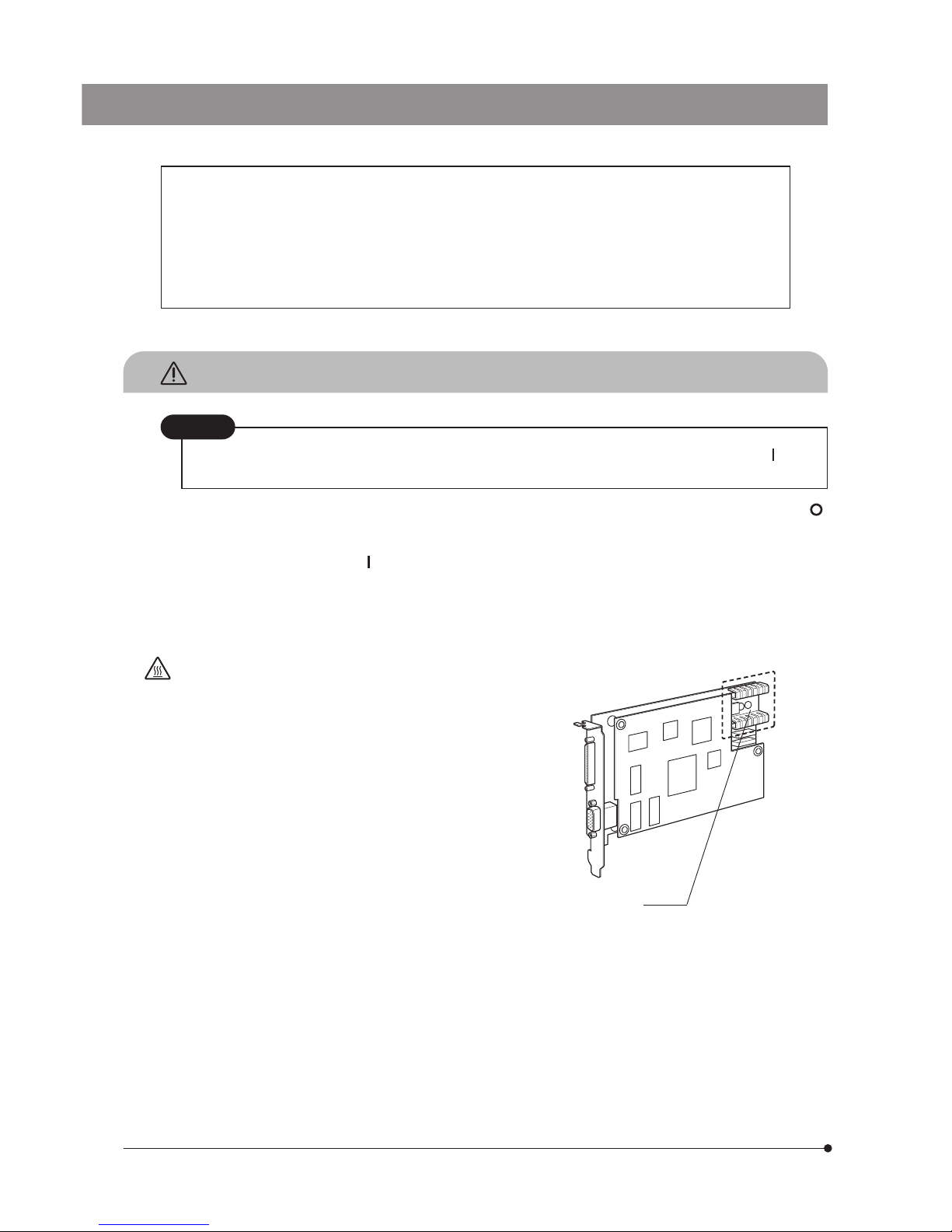
The PCI interface board area shown in the illustration on
the right becomes very hot during and immediately after
use of the camera. Be careful never to touch them during
and after use.
5. Connect the provided power cord correctly and ensure that the
grounding terminal of the power supply and wall outlet are
properly connected. If the equipment is not grounded/earthed,
Olympus can no longer warrant the electrical safety performance
of the equipment.
6. Lay out the interface cable so that it does not contact the heat
generating section such as the lamp housing of the microscope.
Hot part
Page 5

DP71
2
Computer and Software
The computer data may be destroyed by an unexpected event. Be sure to keep the backup of the data.
1. Olympus will not assume any liabilities for any damage incurred due to the use or non-usability of this system, including
compensation for the lost data.
2. The computer used with this system should set up and run Microsoft Windows 2000, XP or Vista.
For the OS in the computer, the user is requested to create a backup and retain it carefully. (Olympus does not support the
matters related to the OS including its backup.)
For details on the computer and Microscope Windows 2000, XP or Vista refer to their respective manuals.
3. Olympus guarantees the quality of this product in the factory shipment condition.
Olympus will not assume any liabilities for the operation errors and functional faults incurred due to the alteration of the
environmental setup (including BIOS change), installation of other software or addition of hardware to the computer by the
user.
4. When the HD free space reduces, the data processing speed may slow extremely or errors may occur frequently. To
prevent this, delete unnecessary data files frequently. For how to delete data files, refer to the manuals for Microsoft
Windows 2000, XP or Vista.
5. Never attempt to delete or rename the folders and files recorded in the provided installer software. Otherwise, the software
may get unable to be started up.
6. Do not open the enclosure of the computer and touch the power supply or the circuit board's heat generating section
right after use as it may burn your hand. Wait until the internal temperature drops sufficiently.
7. Sharp edges inside the computer may cut your fingers, so take extra care.
8. Use a computer that complies with the safety standards of your country.
Page 6

3
1
Conformity of the System
Restrictions
1. The recommended camera adapter is the U-TV0.5XC-3, U-TV0.63XC, MVX-TV0.63XC or the combination U-TV1X-2 +
U-CMAD3.
The U-TV0.5XC should not be used because it deteriorates the image flatness.
A camera adapter with a magnification below 0.5X cannot be used because part of image will be cut off.
2. When the DP71 is connected to the rear port of the U-DPT or U-MPH, the peripheral part of the recorded image may be
deteriorated due to the optical performance of the U-DPT or U-MPH.
3. When the U-TV0.5XC-2 or U-TV0.5XC-3 is used, using two or more intermediate attachments* may obscure or cut off the
peripheral part of the field of view or may make flare noticeable.
* Example of two intermediate attachments: BX microscope + Vertical illuminator + Intermediate attachment with a
length equivalent to the U-CA
4. Under fluorescent ring illumination or other AC-driven illumination such as a phase control light intensity adjusting
illumination system, the following phenomena may be observed when the light intensity is increased and exposure time
is decreased:
· Flickering of the displayed image.
· Instability in exposure.
· Hatching patterns in pixel shift recording (4080 x 3072 or 2040 x 1536 pixels).
However, provided that the brightness can be adjusted using the light intensity control knob is possible or ND filters, the
above phenomena may be attenuated by adjusting the brightness so that the exposure time exceeds 1/50 sec.
For details on the microscope models using AC-driven illumination, consult Olympus.
5. Non-Olympus microscopes and commercially available C-mount lenses can be used provided that they match a CCD
with a size of no less than 2/3 inch and the lens projection length from the C-mount body attaching section is no more
than 6 mm. However, problems due to optical adaptability, such as shading, may be observed.
6. When the specimen has a low contrast (near transparent) or high reflectance (mirror status) and the aperture iris diaphragm
is stopped down near the smallest aperture, spot flare may be noticeable.
7. When the edge of a non-transmitting object is observed under the STM6 transmitted illumination, flare may be noticeable
due to the difference in brightness between the transmitted sections (over-exposure) and non-transmitting section (underexposure). To reduce the flare, set a lower exposure using the exposure correction function or setting the exposure
manually.
8. When a low-power objective (below 4X) is used, the peripheral part of the field of view may be obscured. In this case, use
an ultralow-magnification condenser (U-ULC-2).
9. When the U-CFU is used, it is required to set the exposure to a longer period than 1/30 sec. using the manual exposure
mode and control the brightness by engaging or disengaging ND filters.
10. During recording with image shifting (4080 x 3072 or 2040 x 1536 pixels), the image may be disturbed if the specimen is
moved.
11. If the camera or microscope is vibrated during recording of a 4080 x 3072 or 2040 x 1536 pixel image, the image will be
disturbed. Note that the factors causing vibrations include operation of the keyboard or mouse on the same desktop
where the microscope and camera are installed.
Operating Environment
Temperature: 10 to 35°C. Humidity: 20% to 85% (without condensation).
Page 7

DP71
4
Recommended Computer Specifications
PC/AT compatible
CPU IntelR Processor
Pentium4 1.3 GHz or greater. [2.6 GHz or greater, Hyper-Threading CPU recommended],
Pentium D, Pentium EE, Core2 Duo, Core2 Quad, Core2 Extreme
Chipset Intel
R
845 or later
[In the case of Windows XP or Windows 2000, 865 or later recommended]
[In the case of Windows Vista, 945 or later recommended]
RAM SDRAM, 512 MB or more. [In the case of Windows Vista, 1GB or more recommended]
[PC2700 or greater, dual-channel DDR/DDR2 recommended]
HDD Free space 500 MB or more
Graphic RAM 16 MB or more. [In the case of Windows Vista, 128 MB or more recommended]
AGP graphic card or PCI-Express X16 graphic card
1280 x 1024 or more
32-bits color per pixel
*Onboard graphic also available when the chipset is i915 or later.
PCI bus PCI Rev. 2.1 or 2.2.
OS Windows Vista Business, Ultimate.
Windows XP Professional SP2 or later. (Not compatible with x64 Edition.)
Windows 2000 Professional SP4 or later. (English or Japanese edition)
Drive CD-ROM (or CD-R/RW, etc.)
Main body Half-size PCI board compatible. (See 1. below.)
Power supply 250 W or more. (With CE marking)
1. Computer model
<PC/AT compatible machine> The computer should meet the above specifications. The recommended computers are
the following models that accept a half-size (106.7 mm x 174.6 mm) PCI interface board.
Note that some of the following models may not accept such a board due to the internal structures.
DELL
R
: Prevision Series, Dimension Series, OptiPlex Series.
IBM (Lenovo) : Think Centre Series.
HP : dx Series, xw Series.
2. CPU
We do not guarantee operation if the computer uses a CPU other than Pentium 4, Pentium D, Pentium Extreme Edition,
Core2 Duo, Core2 Quad or Core2 Extreme, and use a chipset other than an Intel chipset.
If the computer uses a CPU other than a Hyper-Threading CPU or a multi core CPU, the movie frame rate may drop.
3. OS
When using Windows Vista, it is required to combine the DP-BSW-V3.3 or later version.
When using Windows 2000, it is required to combine the DP-BSW-V3.2 or earlier version.
4. HD free space
The HD free space refers to the space that does not cause a special problem even when the system is installed or run.
The space required for saving an image file in the HDD is slightly more than 4 MB with a 1360 x 1024-pixel (24-bit) noncompressed image and slightly more than 38 MB with a 4080 x 3072-pixel (24-bit) non-compressed image. In consequence,
the HDD should also provide a considerably large space for saving these image files.
When saving movies in the HDD stack, the space required for saving a movie is about 20 MB (max.) per second. The
movie recording time is limited according to the HD free space.
5. RAM
If a RAM other than a PC2700 or greater, dual-channel DDR/DDR2 RAM is used, the movie frame rate may drop.
6. Monitor
It is recommended to use a monitor capable of 1280 x 1024 or more full-color display.
7. Sequential connection of PCI units
Up to two PCI units including the DP71 and a PCI interface board of the DP70/DP30BW or FV1000 can be connected in
series. However, their simultaneous operation is not available so it is required to select either PCI interface operation.
Page 8

5
2
Getting Ready
1. The camera head uses precision components. Handle it with care and avoid subjecting it to a sudden or severe impact.
2. The image displayed on the monitor may be affected when it is used near equipment generating strong electromagnetic
waves. This is not a malfunction and will not affect the actual image being recorded. To avoid interference during
operation, keep the system far from any source of electromagnetic waves.
3. When mounting the camera head on a tripod, attach it by using the DP-TRAD tripod adapter, which is separately available.
4. Do not use the camera in areas where it may be subjected to direct sunlight, high temperature and humidity, dust or
vibrations. (For the operating environment conditions, see chapter 8, “SPECIFICATIONS” on page 22.)
5. The camera head needs to be calibrated periodically (every 3 months as reference) for the level variations caused by the
influence of cosmic rays. For the calibration method, refer to the Camera Calibration Wizard in the Online Help in the DPBSW software.
3
Maintenance and Storage
1. To clean the lenses and other glass components, simply blow dirt away using a commercially available blower and wipe
gently using a piece of cleaning paper (or clean gauze).
If a lens is stained with fingerprints or oil smudges, wipe it with gauze slightly moistened with commercially available
absolute alcohol.
Since the absolute alcohol is highly flammable, it must be handled carefully.
Be sure to keep it away from open flames or potential sources of electric sparks -- for example, electrical equipment
that is being switched on or off.
Also remember to always use these chemicals only in a well-ventilated room.
2. Parts other than the glass components should be cleaned by wiping with a clean cloth. Do not use organic solvents to
remove major stains. Use a soft cloth slightly moistened with a neutral detergent solution.
3. Do not disassemble any part of the camera as this could result in malfunction or reduced performance.
4
Caution
If the equipment is used in a manner not specified by this manual, the safety of the user may be imperiled. In addition, the
equipment may also be damaged. Always use the equipment as outlined in this instruction manual.
The following symbols are used to set off text in this instruction manual.
: Indicates that failure to follow the instructions in the warning could result in bodily harm to the
user and/or damage to equipment (including objects in the vicinity of the equipment).
# : Indicates that failure to follow the instructions could result in damage to equipment.
} : Indicates commentary (for ease of operation and maintenance).
Page 9
DP71
6
1
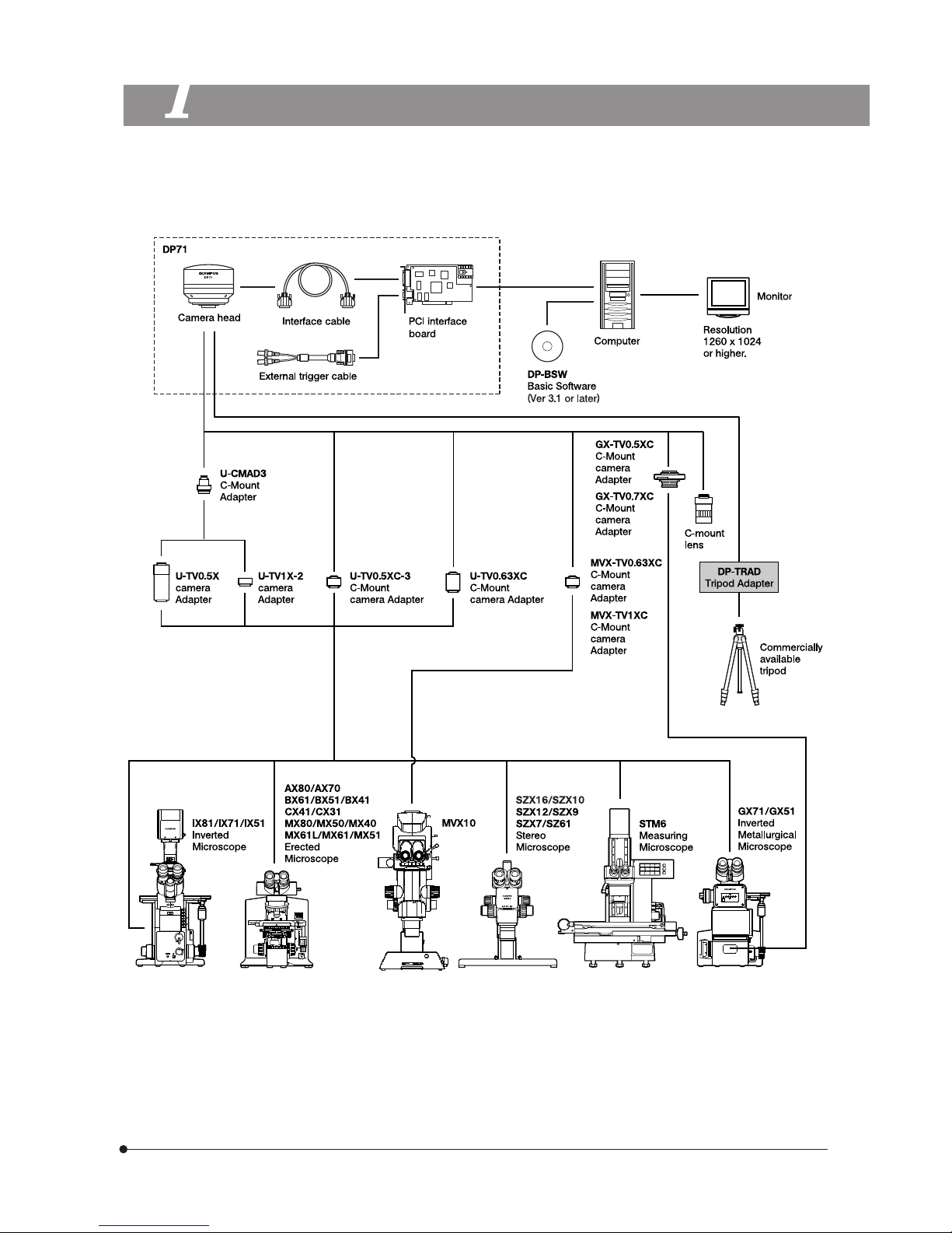
SYSTEM CHART
(Note) Microscopes that are not listed in the above may also be applicable. For details, please consult Olympus.
Page 10
7
NOMENCLATURE
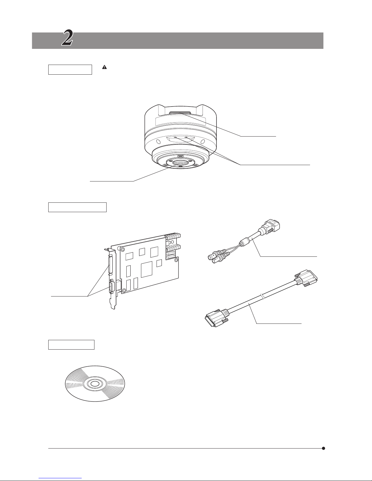
Camera Head
Any equipment connected to the camera head should be an Olympus-designated product or a
product in compliance with the requirements of IEC60950 or CISPR22/24. If equipment other
than these products is connected, Olympus cannot guarantee any performance of the camera.
Connector (P. 10)
C-mount thread (P. 9)
Tripod adapter mount screw (P. 9)
PCI Interface Board
(PCI standard half size)
Connectors (P. 10)
External trigger cable (P. 10)
Interface cable (P. 10)
Basic Software
(CD-ROM)
Page 11
DP71
8
HARDWARE INSTALLATION
Fig. 1
Fig. 2
@
1
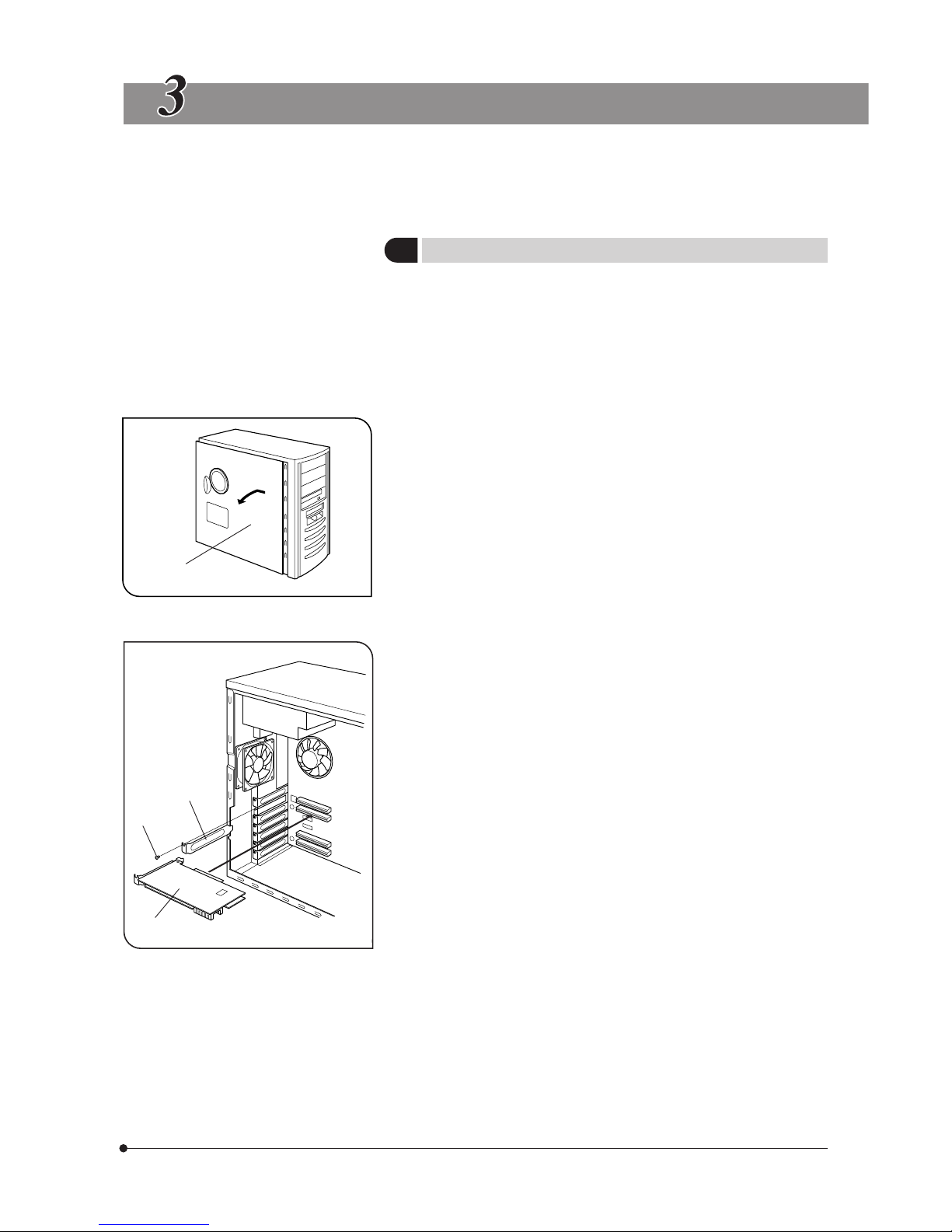
Installing the PCI Interface Board
(Figs. 1 & 2)
#Before installing the PCI interface board in the computer, be sure to
read the instruction manuals for the computer in order not to damage
them.
#Be sure to turn off the computer and peripherals and unplug their
power cords before installing the PCI interface board.
#To avoid damage due to static electricity, touch an unpainted metallic
surface of the computer with your hand to leak the static electricity
before installation.
1. Open the cover @ of the computer.
2. Remove the clamping screw ³ of the slot cover ² of an unused PCI slot
on the motherboard and remove the cover.
3. Insert the PCI interface board | taking care not to touch the board surface
directly by hand, and attach the slot cover using the clamping screw
removed above.
4. Attach the computer cover @ to the original position.
²
³
|
Page 12
9
Fig. 3
Fig. 4
2
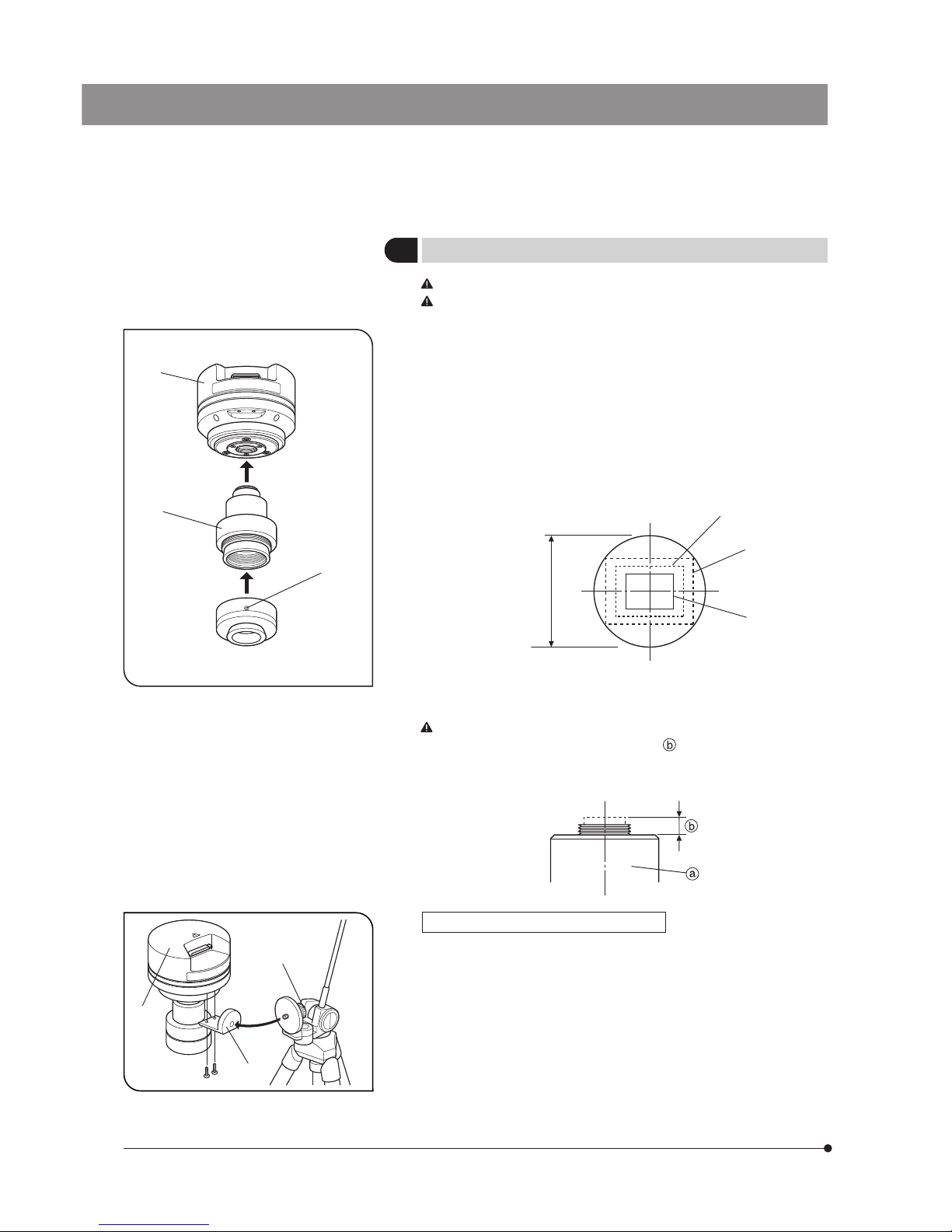
Installing the Camera Head
(Figs. 3 & 4)
The C-mount screw has a sharp edge that should not be touched.
The camera head and camera adapter are precision modules. Be
careful not to drop them during attaching or detaching.
}The following procedure deals with the case using the combination of
the U-TV1X-2 camera adapter + U-CMAD3 C-mount adapter.
1. Screw in the U-CMAD3 C-mount adapter @ into the C-mount thread on
the bottom of the camera head ².
Then, loosen the clamping screw ³ at the bottom of the U-TV1X-2 camera
adapter, screw in the camera adapter into the C-mount adapter and tighten
the clamping screw.
· As the photographed field is as shown below, use a camera adapter
having magnification of 0.5X to 1X. (If a 0.35X camera adapter is used, the
peripheral part of the image will be obscured.)
Field number
22
0.63X (FN 17.5)
0.5X (FN 22)
1X (FN 11)
· If a C-mount camera adapter from other manufacturer than Olympus is
used, the optical performance of the system may not be manifested fully.
Be careful in using other manufacturer’s C-mount camera adapter
or C-mount lens having a thread length over 6 mm. Otherwise, the
threaded section will hit the inside of the camera head and cause
damage to it.
Using a Commercially Available Tripod
}The DP-TRAD tripod adapter is provided with two types of screws (2 each)
and an Allen wrench. Use only the Phillips screws (x 2) with the DP71.
1. Attach the DP-TRAD tripod adapter | to the camera head 5 and clamp
them using the provided Phillips screws (x 2) with a Phillips screwdriver.
2. Attach the tripod to the tripod adapter | and tighten the tripod’s clamping
knob 6 to secure the camera head.
²
@
³
5
6
|
Page 13
DP71
10
Fig. 5
Fig. 6
Fig. 7
3
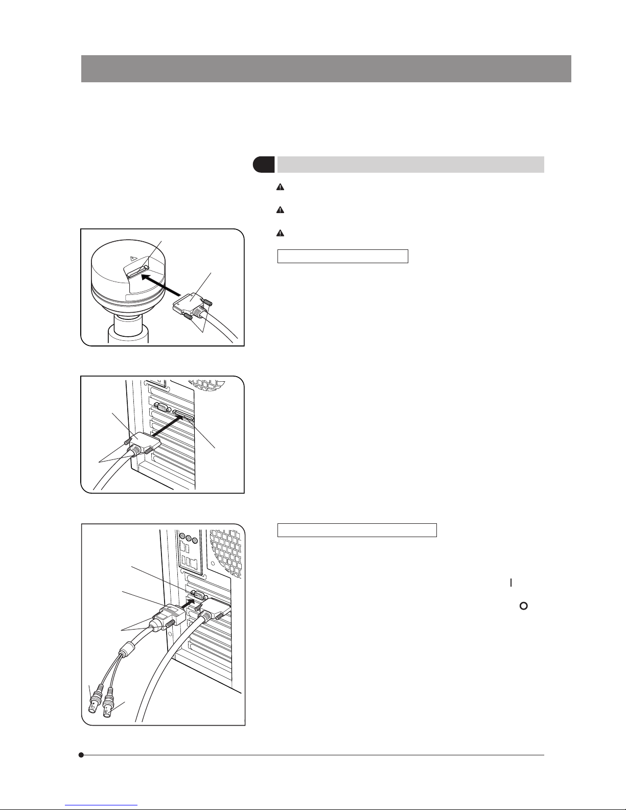
Connecting the Cables
The cords and cables are vulnerable to bend or twist. Do not apply
excessive force to them.
Be sure to switch off the computer before proceeding to the
connections.
Always use the cables designated by Olympus.
Connecting the Interface Cable
1. Connect the connector @ on one end of the interface cable to the
connector ² on the PCI interface board, tighten the lock screws ³ on
the interface cable’s connector and check that the cable will not slip out.
2. Connect the connector | on the other end of the interface cable to the
connector 5 on the camera head, tighten the lock screws 6 on the
interface cable’s connector and check that the cable will not slip out.
Connecting the External Trigger Cable
1. Connect the connector @ of the external trigger cable to the connector
² on the PCI interface board, tighten the lock screws ³ on the external
triggering cable’s connector and check that the cable will not slip out.
2. When using the trigger input, connect the red cable (marked “ ” ) to the
BNC connector |.
3. When using the trigger output, connect the blue cable (marked “ ” ) to
the BNC connector 5.
²
@
³
|
5
6
@
5
²
³
|
Page 14
11
4. Insert the CD-ROM in the CD-ROM drive.
5. Browse CD-ROM by Windows Explorer.
6. Run [Setup.exe].
When the OS is Windows
R
Vista or Windows R XP
The software cannot be installed unless the user account is registered as “computer administrator.”
If the user account is registered as a “Restricted account,” change it to the “Computer administrator” account.
(For the user account registration, refer to the instruction manuals for your computer.)
When the OS is Windows
R
2000
Log on as a user with the Administrator authority and make sure that you have the access rights to the following locations.
(For the access rights, refer to the instruction manuals for your computer.)
· Folder for installing this software.
· Windows System folder and System registry.
Trademark Information
SOFTWARE INSTALLATION
}This chapter describes the installation of the optionally available DP-BSW Basic Software for DP71.
Before Installation
Windows is a registered trademark of Microsoft Corporation.
All other brand and product names are trademarks or registered trademarks of their respective owners.
1
Installation Procedure
The device driver can be installed automatically during installation of the application software.
It is recommended to use the automatic installation facility for installing the device driver.
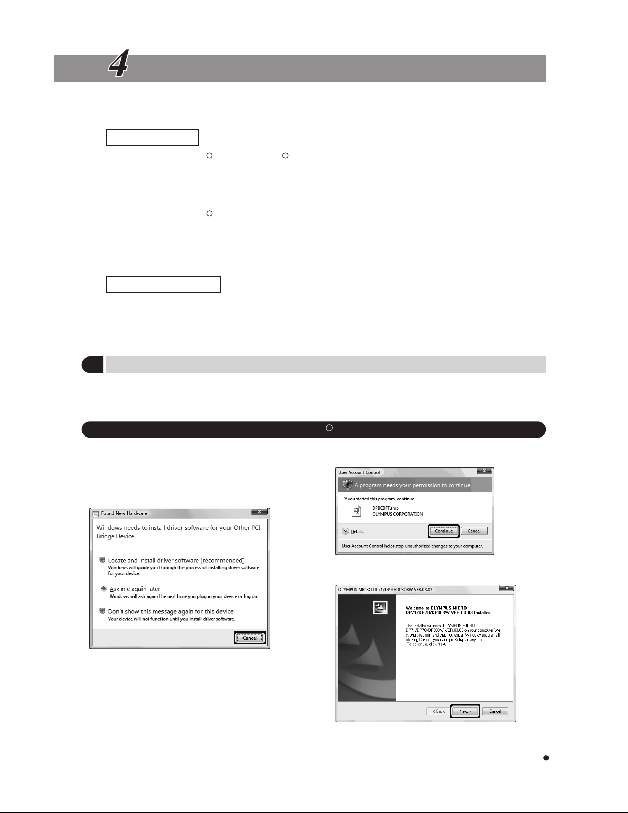
1. WindowsR Vista
1. Ensure that the PCI interface board is installed in the PCI
card slot of the computer.
2. Start Windows Vista. (Log on with the Computer Administrator
account.)
3. When the following window appears in a while, click on the
[Cancel] button to close the window.
7. The [User Account Control] dialog box appears. Then click
on the [Continue] button.
8. Before proceeding to installation, close all running
applications. Then click on the [Next] button.
Page 15
DP71
12
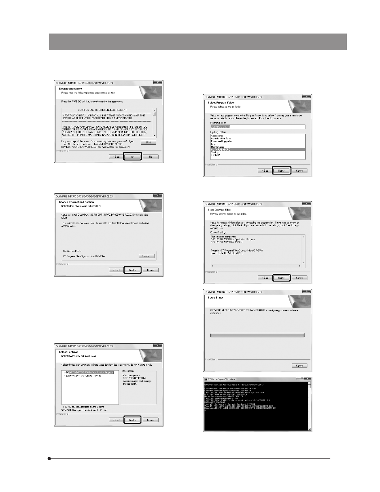
9. Read the displayed License Agreement. If you agree with it,
click on the [Yes] button.
10. The [Choose Destination Location] window appears. If you
want to change the installation destination, click on the
[Browse] button and specify the new installation destination.
Then click on the [Next] button.
11. The [Select Features] window appears. Check the
components to be used and click on the [Next] button.
a) DP71/DP70/DP30BW Application Program
Checking this installs the application, which allows you
to control the DP71 for recording images and manage
the images in a simplified manner using thumbnails.
b) DP71/DP70/DP30BW TWAIN
Checking this installs the program, which allows you to
download images directly from the DP71 to another
TWAIN/IF-compatible application such as Photoshop.
12. The [Select Program Folder] window appears. If you want to
change the program folder, change the name under
[Program Folders] or select a folder under [Existing Folders].
Then click on the [Next] button.
13. The [Start Copying Files] window appears. When the actual
installation is ready, click on the [Next] button. This starts
installation of the application software.
Page 16
13
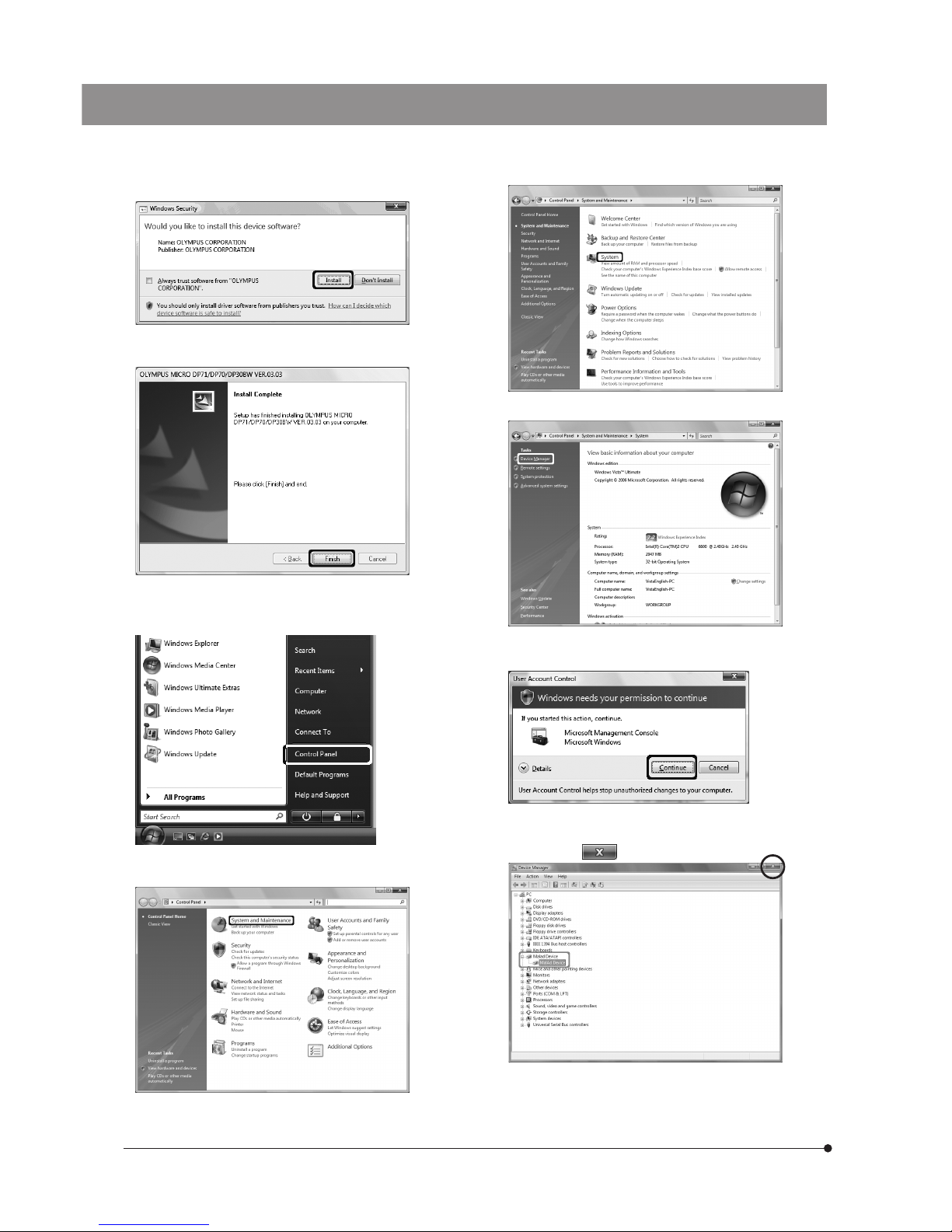
14. When the [Windows Security] dialog box appears, then click
on the [Install] button.
15. When the installation completes, the window below appears.
Then click on the [Finish] button.
16. Take out the CD-ROM.
17. Click on the <Start> button. When the [Start] menu is displayed,
click on [Control Panel].
19. Click on [System].
20. Click on the <Device Manager> button in the “Tasks".
21. When the [User Account Control] dialog box appears, click
on the [Continue] button.
22. If the driver has been properly installed, “MalAd Device"
should be displayed as shown below. After confirming this,
click on the < > button.
Now the software has been installed.
18. When the [Control Panel] dialog box is displayed, click on
[System and Maintenance].
If the [Control Panel] display is of the “Classic View" type,
double-click on the [System] icon and go to step 20 below.
Page 17
DP71
14
2. WindowsR XP, WindowsR 2000
1. Ensure that the PCI interface board is installed in the PCI
card slot of the computer.
2. Start Windows XP. (Log on with the Computer Administrator
account.)
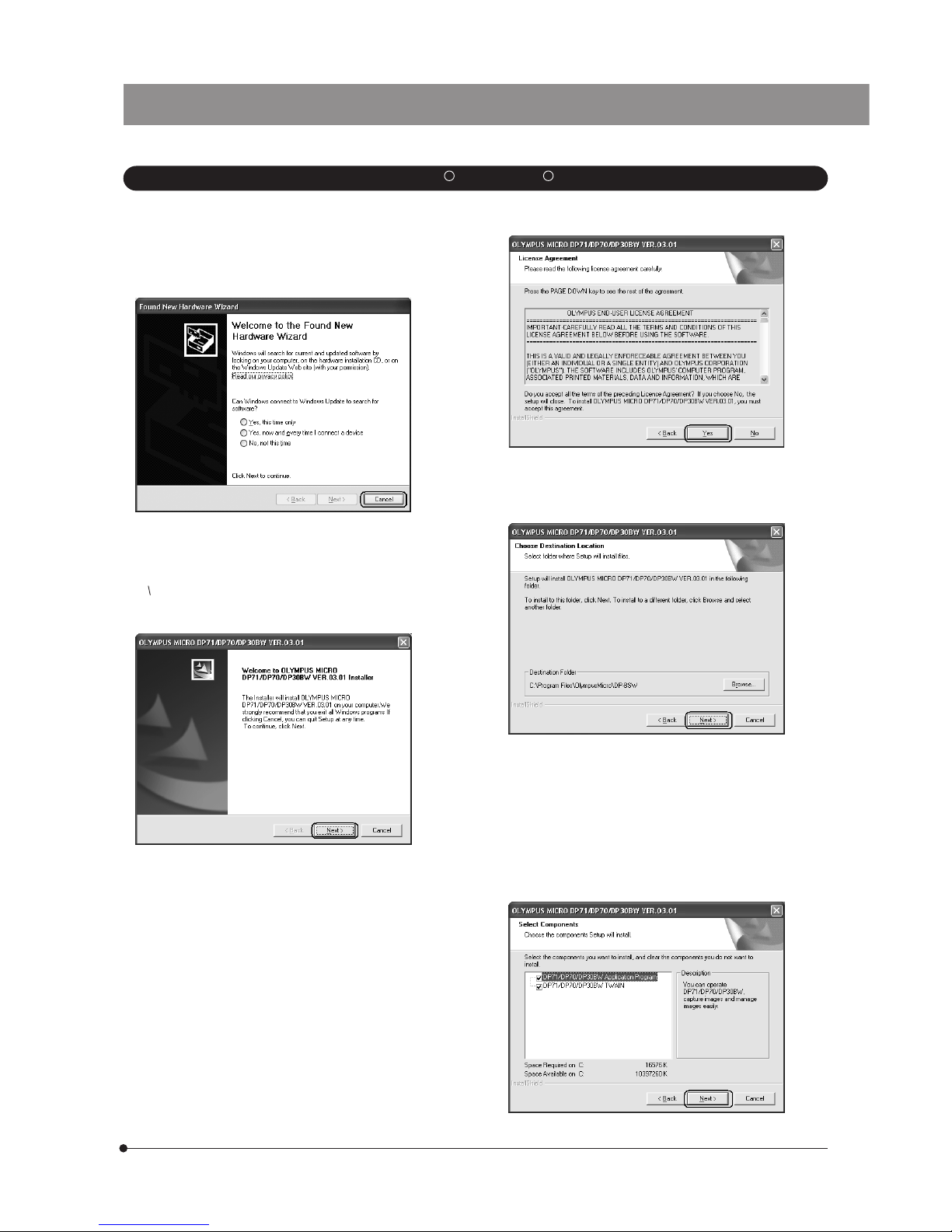
3. When the following window appears in a while, click on the
[Cancel] button to close the window.
4. Insert the CD-ROM in the CD-ROM drive.
5. Click on the [Start] button in the Windows taskbar.
6. Select [Run].
7. Enter the following and click on the [OK] button.
D: setup.exe
If your CD-ROM drive is not drive D, enter the correct drive character
instead of “D.” Now the installation program starts up.
8. Before proceeding to installation, close all running
applications.
Then click on the [Next] button.
10. The [Choose Destination Location] window appears. If you
want to change the installation destination, click on the
[Browse] button and specify the new installation destination.
Then click on the [Next] button.
11. The [Select Components] window appears. Check the
components to be used and click on the [Next] button.
a) DP71/DP70/DP30BW Application Program
Checking this installs the application, which allows you
to control the DP71 for recording images and manage
the images in a simplified manner using thumbnails.
b) DP71/DP70/DP30BW TWAIN
Checking this installs the program, which allows you to
download images directly from the DP71 to another
TWAIN/IF-compatible application such as Photoshop.
9. Read the displayed License Agreement. If you agree with it,
click on the [Yes] button.
Page 18
15
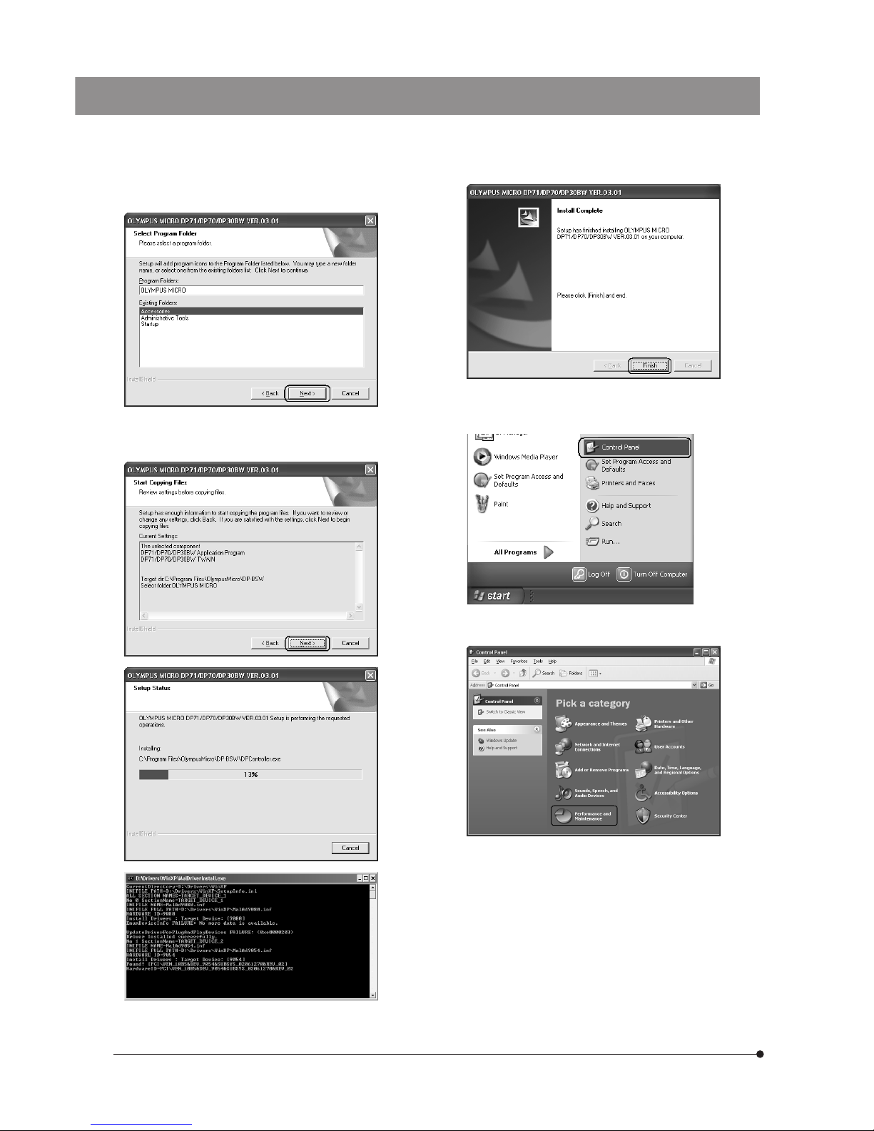
12. The [Select Program Folder] window appears. If you want to
change the program folder, change the name under
[Program Folders] or select a folder under [Existing Folders].
Then click on the [Next] button.
14. When the installation completes, the window below appears. Then click on the [Finish] button.
13. The [Start Copying Files] window appears. When the actual
installation is ready, click on the [Next] button. This starts
installation of the application software.
15. Take out the CD-ROM.
16. Click on the <Start> button. When the [Start] menu is displayed,
click on [Control Panel].
17. When the [Control Panel] dialog box is displayed, click on
[Performance and Maintenance].
If the [Control Panel] display is of the classic type, doubleclick
on the [System] icon and go to step 19 below.
Page 19
DP71
16
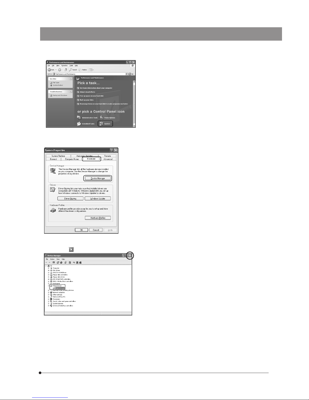
18. Click on [System].
19. When the [System Properties] dialog box is displayed, click
on the [Hardware] tab and then click on the <Device Manager> button.
20. If the driver has been properly installed, “MalAd Device"
should be displayed as shown below. After confirming this,
click on the < > button.
Now the software has been installed.
Page 20
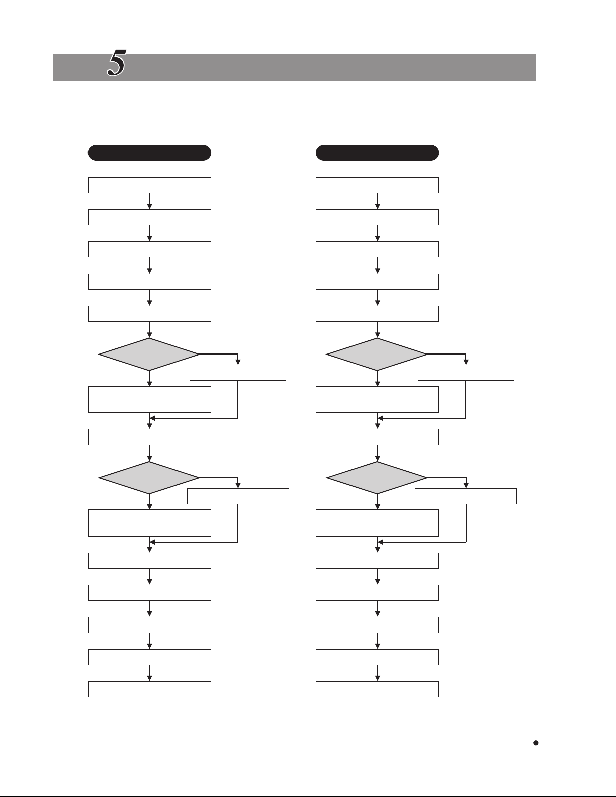
17
IMAGE RECORDING PROCEDURE
(Notes) The encircled numbers indicate the control positions in the windows shown on the next page.
For detailed operating procedures, refer to the Online Help for the DP Controller and DP Manager.
Brightfield Observation Fluorescence Observation
Launch DP Manager. Launch DP Manager.
Launch DP Controller. Launch DP Controller.
Set up the microscope. Set up the microscope.
Display the preview image.
@
Display the preview image.
@
Set the exposure mode.
²
Set the exposure mode.
²
Exposure mode?
Manual
Exposure mode?
Manual
Auto
Set the exposure time.
³
SFL Auto
Set the exposure time.
³
Select the metering area (30%,
1% or 0.1%).
|
Select the metering area (30%,
1% or 0.1%).
|
Perform framing and focusing. Perform framing and focusing.
Exposure mode?
Manual
Exposure mode?
Manual
Fine-adjust the exposure time.
³
Fine-adjust the exposure time.
³
Auto SFL Auto
Move the metering area and
correct exposure.
5
Move the metering area and
correct exposure.
5
Adjust the white balance.
6
Adjust the black balance.
8
Record an image.
7
Record an image.
7
Select DP Manager. Select DP Manager.
Perform zooming or scrolling.
9
Perform zooming or scrolling.
9
Save the image.
a
Save the image.
a
Page 21
DP71
18
DISPLAYED WINDOWS
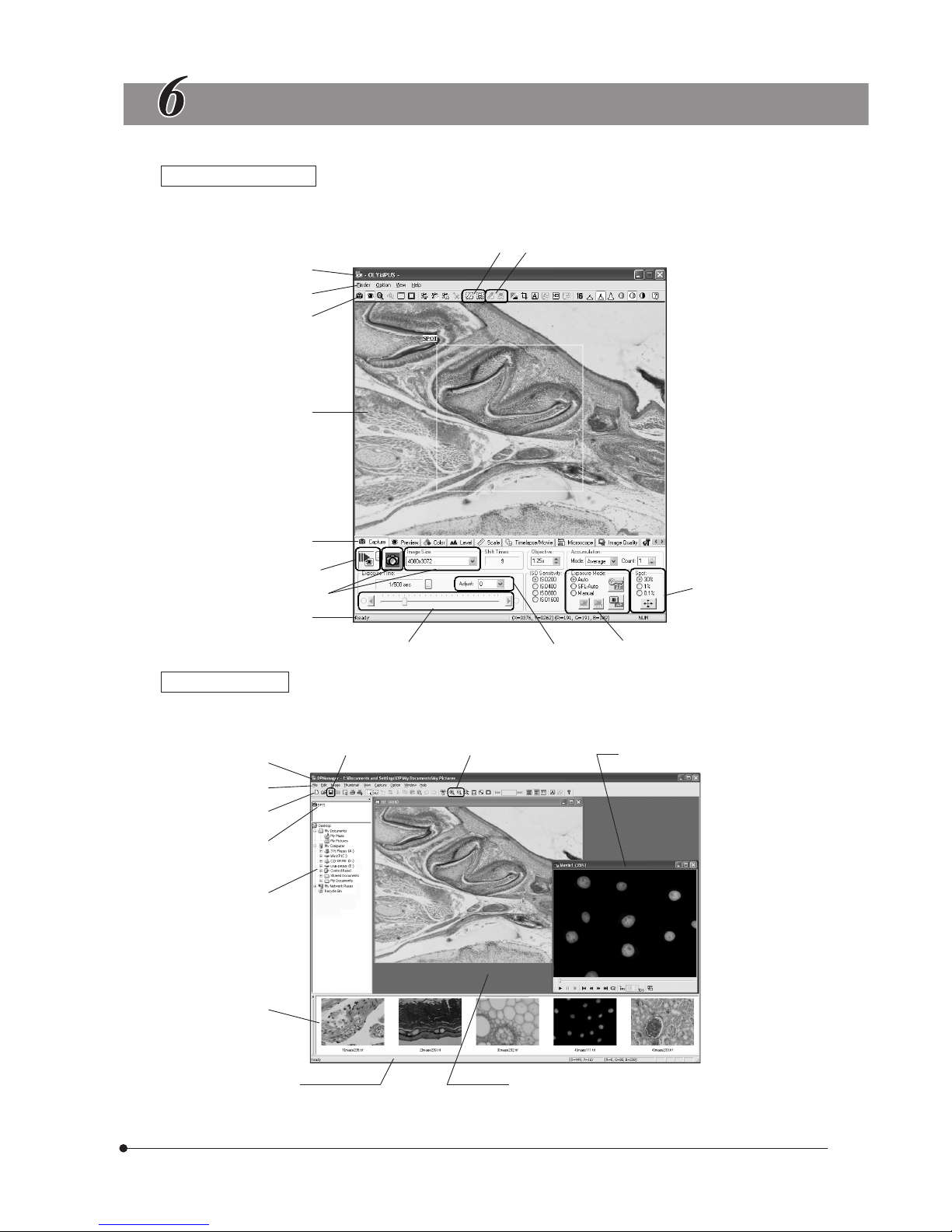
Image Record Window
}This window is displayed at the startup and used to record still images and movies. For details, refer to the Online Help
of the DP Controller. The Online Help can be viewed by opening the [Help] menu and selecting [Help].
Title bar
Menu bar
Tool bar
Preview area
Control tab
Status bar
@
²
³
|
5
6
7
8
Edit/Save Window
}This window is sued to edit, save and display images. For details, refer to the Online Help of the DP Manager. The Online
Help can be viewed by opening the [Help] menu and selecting [Help].
Title bar
Menu bar
Tool bar
Camera icon *
Folder bar
Thumbnail bar
Status bar
Movie window
Window display area
9
a
* The camera name shown on the camera icon is the last camera name used with the DP Controller. The camera name
shown immediately after installation may be “DP71/DP70/DP30BW.”
Page 22
19
EXTERNAL TRIGGERING
}The DP71 can record still images or control a commercially available shutter based on an external trigger signal.
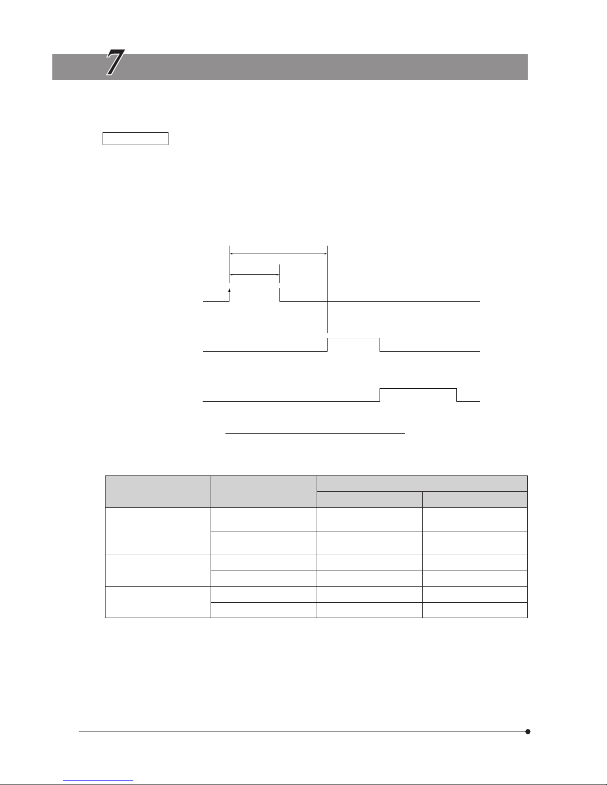
Trigger Input
· The trigger input from external equipment can be used to start still image recording using the DP-BSW.
· The trigger input is detected at the edge, and the positive and negative logics can be switched with the DP Controller.
· The trigger input is not compatible with random triggering. Due to a time lag of 150 to 600 ms after the trigger input, the
exposure start time cannot be synchronized completely
For details on the time lag from the trigger input to the start of exposure, see table below.
· The trigger input is a TTL compatible signal.
V
IH
: 2.0 V (min.). VIL: 0.8 V (max.).
Trigger input
Exposure
Readout &
transfer to
PC
150 to 600 msec.
5 msec. or more
Trigger Input Timing Chart (Positive logic)
Table Time Lag from Trigger Input to Exposure Start
Recording Image Size
Preview Status at Trigger Input
Time Lag from Trigger Input to Exposure Start (msec.)
Min. Max.
4080 x 3072
2040 x 1536
1360 x 1024
680 x 512
OFF 150 400
ON 210 600
680 x 510
(2 x 2)
OFF 150 350
ON 210 500
340 x 250
(4 x 4)
OFF 150 300
ON 210 350
Page 23

DP71
20
Trigger Output
· The trigger output can be used to control a commercially available shutter.
· The positive and negative logics of the trigger output can be switched with the DP Controller.
· The trigger output is interlocked with the shutter release/close operations of the DP Controller.
· The external trigger signal is output by starting still image recording when the shutter is closed.
· The time lag from the trigger output to the start of exposure can be set between 0 and 2 sec. on the DP Controller.
· The trigger output is a TTL compatible signal.
V
OH
: 2.4 V (min.). VOL: 0.4 V (max.).
Trigger output
Exposure
Readout &
transfer to
PC
Exposure time lag
Trigger Output Timing Chart in Still Image Recording (Positive logic)
Page 24
21
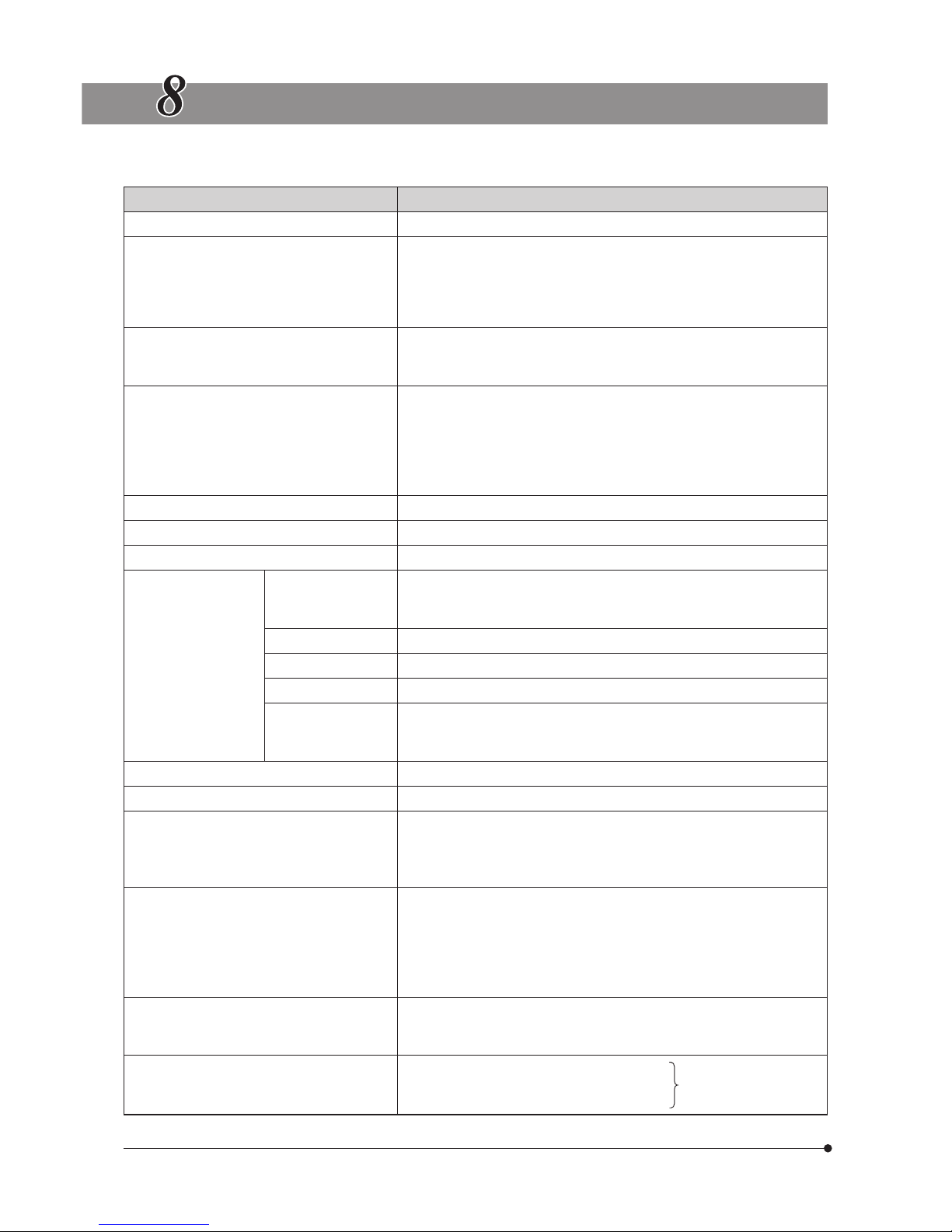
SPECIFICATIONS
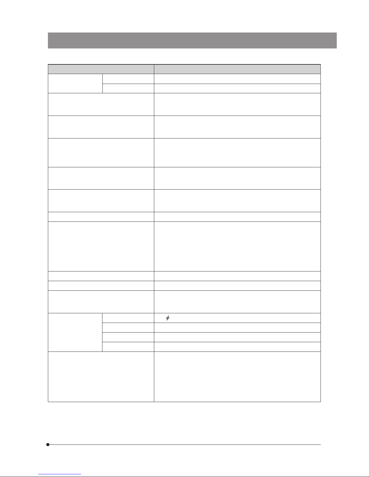
DP71 Specifications
Item Specifications
Camera system Single-CCD color camera (pixel shifting).
Image pickup device 2/3-inch color CCD.
Total pixels: 1.5 million pixels.
Effective pixels: 1.45 million pixels.
Pixel pitch: 6.45 μm (H) x 6.45 μm (V).
Scanning method: Progressive scanning.
Cooling Peltier cooling.
Natural air cooling.
CCD temperature: Room temperature --10°C (max.)
Recorded image sizes 4080 x 3072 (1 x 1, pixel shifting),
2040 x 1536 (1 x 1, pixel shifting),
1360 x 1024 (1 x 1),
680 x 512 (1 x 1),
680 x 510 (2 x 2),
340 x 250 (4 x 4)
Lens mount C-mount
ISO speed ISO 200/400/800/1600 equivalent
A/D 12 bits
Exposure control*
Exposure modes Auto,
SFL Auto,
Manual
AE lock Available
AE pause Available
Exposure correction Correction range: ±2.0 EV. Step: 1/3 EV
Metering area 30%,
1%,
0.1%. The metering area is freely movable.
Exposure time 1/44,000 to 60 sec.
Binning 2 x 2, 4 x 4
Movie frame rate** 1360 x 1024 (1 x 1): 15 fps.
680 x 512 (1 x 1): 15 fps.
680 x 510 (2 x 2): 29 fps.
340 x 250 (4 x 4): 57 fps.
Still image recording time**
(From exposure start to display)
4080 x 3072 (1 x 1): Approx.3.0 sec.
2040 x 1536 (1 x 1): Approx.2.5 sec.
1360 x 1024 (1 x 1): Approx.0.7 sec.
680 x 512 (1 x 1): Approx.0.6 sec.
680 x 510 (2 x 2): Approx.0.5 sec.
340 x 250 (4 x 4): Approx.0.4 sec.
Color modes Color,
standard gray scale,
custom gray scale
External triggering
Input: Event trigger input.
Output: Trigger output. With exposure time lag
(0 to 2 sec. in 10 msec. steps).
Compatible with TTL
Page 25
DP71
22
Item Specifications
Image accumulation* Modes Integral, averaging
Accumulation count 64 frames (max.)
White balance Modes* Area-specified auto,
Entire area-specified auto,
Manual
Black balance Modes* Area-specified auto,
Entire area-specified auto,
Manual
Contrast modes* Low,
Standard,
High,
Linear.
Sharpness filter* Low,
Standard,
High.
Focus indicator* Contrast bar,
numeric display,
histogram.
Interval recording* Interval: 1 sec. to 24 h.50 m.59 sec. Number of shootable frames: 3000
Image file formats* TIFF (16/48-bit) with 10 bits/CH effective pixels,
TIFF (8/24-bit),
JPEG,
BMP,
PICT,
AVI,
MPEG-1.
Preview quality modes* Standard, Medium, High.
Computer interface PCI bus interface: PCI Rev. 2.1 and 2.2 compatible.
Compatible OS*** Windows Vista Business/Ultimate
Windows XP Professional SP2. (Not compatible with the x64 Edition.)
Windows 2000 Professional SP4. (English or Japanese edition)
Dimensions & weight
Camera head 112( ) x 75(H) mm (excluding projections), approx. 1,150 grams
PCI unit 187.4(W) x 125.7(D) x 21.4(H) mm (excluding projections), approx. 250 grams
Interface cable Approx. 2.8 meters
External trigger cable Approx. 0.2 meter
Operating environment · Indoor use.
· Altitude: Max. 2000 meters
· Ambient temperature: 10° to 35°C (50° to 95° F)
· Relative humidity: 20% to 85% (without condensation)
· Supply voltage fluctuations; ±10%.
· Pollution degree: 2 (in accordance with IEC60664)
· Installation/Overvoltage category: II (in accordance with IEC60664)
* These items can be set from the DP-BSW. (Ver 3.1 or later)
** The values of these items are variable depending on the exposure time setting and the computer operating situations.
*** The combination with the DP-BSW-V3.2 or earlier is not compatible with Windows Vista.
The combination with the DP-BSW-V3.3 or later is not compatible with Windows 2000.
Page 26

23
TROUBLESHOOTING GUIDE
Under certain conditions, the performance of the camera may be adversely affected by factors other than defects. If
problems occur, please review the following list and take remedial action as needed. If you cannot solve the problem after
checking the entire list, please contact Olympus for assistance.
Problem Cause Remedy Page
a) The computer will not start up. The PCI interface board is not inserted
completely into the computer's PCI slot.
Turn off the computer, unplug the power
cord and insert the PCI interface board
into the computer's PCI slot securely.
8
b) Software will not start up. The camera and computer are connected
improperly.
Turn off the computer and connect
the camera and PCI interface board
properly using the interface cable.
8, 10
The PCI interface board is inserted into
the computer's PCI slot improperly.
Turn off the computer, unplug its power
cord and insert the PCI interface board
into the computer's PCI slot.
8
The device driver is installed improperly. Install the device driver.
11- 16
c) Live image is not displayed. The camera and computer are connected
improperly.
Turn off the computer and connect
the camera and PCI interface board
properly using the interface cable.
8, 10
The microscope illumination is off.
The microscope is not set to the camera
light path.
The illumination or specimen focusing
is adjusted improperly.
Turn on the microscope illumination,
adjust the lighting and focusing
correctly, and select the camera light
path.
–
The ISO speed or exposure time is set
improperly.
Set the ISO speed, exposure mode,
exposure time and level properly.
(Online
manual)
d) Still images cannot be recorded. The camera and computer are connected
improperly.
Turn off the computer and connect
the camera and PCI interface board
properly using the interface cable.
8, 10
The DP Controller is processing recording. Wait until the recording processing
completes before starting recording
of the next image. In certain cases, it
may be required to press the Cancel
button of the progress bar and record
the image again.
(Online
manual)
The DP Manager is processing file save, etc. Wait until the processing completes
before starting recording of the next image.
(Online
manual)
The computer memory is insufficient. Close the image being displayed on
the DP Manager or close other software
before retrying recording.
–
e) Picture is too bright.
Exposure correction is set in the +
direction.
Return the exposure correction value
to 0 and set the desired exposure
correction value.
(Online
manual)
The metering area is set to a dark area
outside the region of interest.
Move the metering area to the area where
you want to obtain optimum exposure
(Online
manual)
AE lock, which was set when the
exposure time was longer than the
currently required exposure time, is active.
Cancel AE lock.
(Online
manual)
The input highlight level adjustment is
too low.
Reset the current level adjustment
and adjust the optimum level again.
(Online
manual)
The microscope illumination is too
bright.
Reduce the microscope illumination
intensity or engage an ND filter to
reduce brightness.
–
Page 27

DP71
24
Problem Cause Remedy Page
f) Picture is too dark. Exposure correction is set in the -
direction.
Return the exposure correction value
to 0 and set the desired exposure
correction value.
(Online
manual)
The metering area is set to a bright area
outside the region of interest.
Move the metering area to the area
where you want to obtain optimum
exposure.
(Online
manual)
AE lock, which was set when the
exposure time was shorter than the
currently required exposure time, is active.
Cancel AE lock.
(Online
manual)
The output highlight level adjustment is
too low.
Reset the current level adjustment
and adjust the optimum level again.
(Online
manual)
The microscope illumination is too dark. Increase the microscope illumination
intensity or disengage the existing ND
filter to increase brightness.
–
g) The colors in the picture are
strange.
The area selected in white balance
adjustment was improper.
Select a white area as the rectangular
white balance adjustment area.
(Online
manual)
The RGB balance is adjusted improperly
in manual white balance adjustment.
Perform manual white balance
adjustment to adjust the RGB color
balance to obtain optimum colors.
(Online
manual)
The area selected in black balance
adjustment was improper.
Select a black area as the rectangular
black balance adjustment area.
(Online
manual)
The screen color setting of the computer
is incorrect.
Set the computer display color to 24bit color or higher. The recommended
setting is 32-bit color.
–
h) The picture is not in focus. The microscope is not focused properly. Adjust the focus correctly with the fine
adjustment knob.
–
The aperture iris diaphragm of the
condenser is open too wide.
Close the aperture iris diaphragm a
little.
–
The field iris diaphragm is not set
properly.
Adjust the field iris diaphragm until the
image circumscribes the field of view.
–
Lens components of the microscope are
contaminated or the cover glass on the
front of the camera is stained.
Clean the objective, photography lens,
condenser and/or window lens of the
microscope, or clean the cover glass
on the bottom of the camera head.
5
The microscope and/or camera are
subjected to vibration during recording.
Record images in an environment in
which the microscope and camera
are not vibrated. It is effective to use
an anti-vibration bench.
–
i) The 4080 x 3072 and 2040 x 1536
images are not neat.
The camera is subjected to vibration
during recording.
Record images in an environment in
which the microscope and camera
are not vibrated. It is effective to use
an anti-vibration bench.
–
j) The DP Controller window is not
displayed correctly. Or the menu
characters are not displayed
correctly.
The resolution setting of the screen is
not correct.
Set the resolution setting at 1280 x 1024
or more in the property of the screen.
–
A large font has been selected in the
font size of the screen.
Select a small font in the property of
the screen.
–
k) External trigger signal is not
output.
External triggering is not enabled. Enable external triggering on the DP
Controller.
(Online
manual)
l) Still image cannot be recorded
using the external trigger input.
External triggering is not enabled. Enable external triggering on the DP
Controller.
(Online
manual)
Page 28

25
SOFTWARE UNINSTALLATION
1. WindowsR Vista
1. Click on the [Start] button and select [Control Panel].
2. Click on [Uninstall a Program] under [Programs].
3. When the [Uninstall or change a program] window appears, select [OLYMPUS MICRO DP71/DP70/DP30BW] and click on
the [Uninstall] button.
4. When the [User Account Control] dialog box appears, click on the [Continue] button.
5. When the [OLYMPUS MICRO DP71/DP70/DP30BW] window appears, select [Remove] and click on the [Next] button.
6. When the [Confirm File Deletion] window appears, click on the [OK] button.
7. Click on the [Finish] button. Now the application program is deleted.
2. WindowsR XP
1. Click on the [Start] button and select [Control Panel].
2. Click on [Add or Remove Programs].
3. When the [Add or Remove Programs] window appears, select [OLYMPUS MICRO DP71/DP70/DP30BW] under [Currently
installed programs] and click on the [Change/Remove] button.
4. When the [OLYMPUS MICRO DP71/DP70/DP30BW] window appears, select [Remove] and click on the [Next] button.
5. When the [Confirm File Deletion] window appears, click on the [OK] button.
6. Click on the [Finish] button. Now the application program is deleted.
3. WindowsR 2000
1. Click on the [Start] button and select [Settings] - [Control Panel].
2. Double-click on [Add/Remove Programs].
3. When the [Add or Remove Programs] window appears, select [OLYMPUS MICRO DP71/DP70/DP30BW] under [Currently
installed programs] and click on the [Change/Remove] button.
4. When the [OLYMPUS MICRO DP71/DP70/DP30BW] window appears, select [Remove] and click on the [Next] button.
5. When the [Confirm File Deletion] window appears, click on the [OK] button.
6. Click on the [Finish] button. Now the application program is deleted.
Page 29

MEMO
Page 30

MEMO
Page 31

Page 32

Shinjuku Monolith, 3-1, Nishi Shinjuku 2-chome, Shinjuku-ku, Tokyo, Japan
Postfach 10 49 08, 20034, Hamburg, Germany
3500 Corporate Parkway, P.O. Box 610, Center Valley, PA 18034-0610, U.S.A.
One Corporate Drive, Orangeburg, NY 10962, U.S.A.
491B River Valley Road, #12-01/04 Valley Point Office Tower, Singapore 248373
31 Gilby Road, Mount Waverley, VIC., 3149, Australia
5301
Blue Lagoon Drive, Suite 290 Miami, FL 33126, U.S.A.
Printed in Japan on December 04, 2007 M 010–@
 Loading...