

Olympus DCN, DCN4, DCN2, DCN1, DCN3 Installation Instructions Manual
...
Installaon Instrucons Page 1
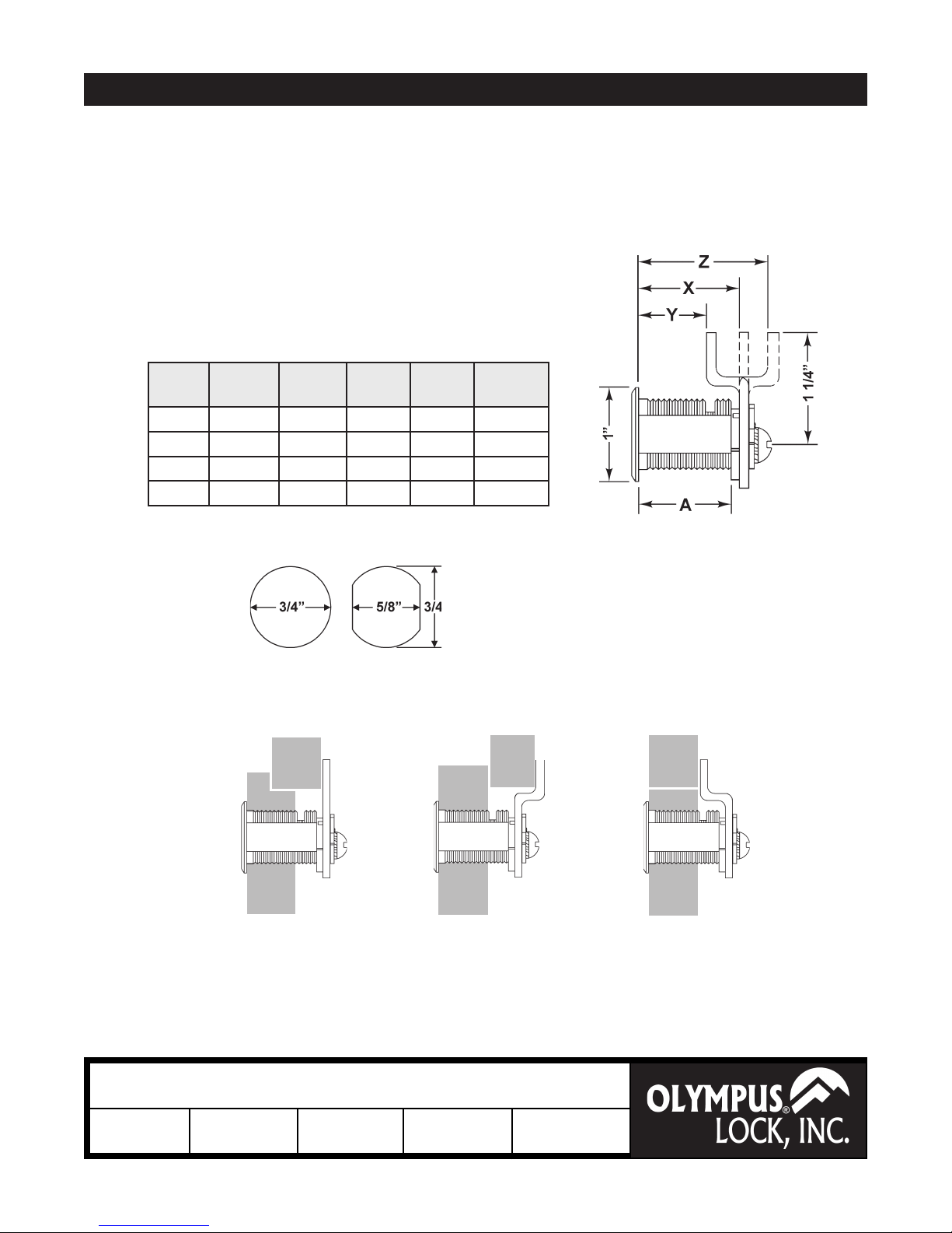
DCN Series
Cam Lock Dimensions
For Mat.
Thickness
DCN1 3/4" 1-1/16" 3/4" 1-3/8" 1"
DCN2 7/8" 1-3/16" 7/8" 1-1/2" 1-1/8"
DCN3 1-1/8" 1-7/16" 1-1/8" 1-3/4" 1-3/8"
DCN4 1-1/2" 1-13/16" 1-1/2" 2-1/8" 1-3/4"
Straight
Cam (X)
Inbent
Cam (Y)
Outbent
Cam (Z)
Cylinder
Length (A)
Mounng Cutout
Lipped/
Overlay
Overlay
Flush
Title
Installaon instrucons for DCN series cam lock
Series
DCN
Barrel Length
See Chart
Bolt type
Cam Lock
Mounting
Surface
Revision Date
11/2012
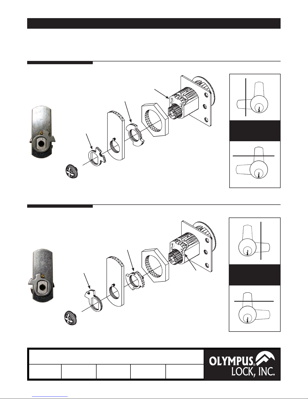
Installaon Instrucons Page 2
All below congurations can be used with straight cam
DCN
or oset cam (in either the inbent or outbent position).
Function:
right-hand door,
vertical drawer
Outer cam
driver
Rear view
Function:
Hole
position
Reversible
cam stop
Cam installation:
Place pin of reversible cam stop in hole #1.
Place cam as pictured above. Assemble outer
cam driver so that the pin from the cam is to
left of the “ears.” Screw in cam screw until tight.
DOOR
360° key rotation
Key removable at cam
positions 9:00 and 12:00
DRAWER
DOOR
left-hand door,
vertical drawer
Outer cam
driver
Rear view
Title
Installaon instrucons for DCN series cam lock
Series
DCN
Barrel Length
See Chart
Bolt type
Reversible
cam stop
Cam installation:
Place pin of reversible cam stop in
hole #2. Place cam as pictured above.
Assemble outer cam driver so that the
pin from the cam is to right of the “ears.”
Screw in cam screw until tight.
Cam Lock
Mounting
Surface
Revision Date
11/2012
Hole
position
360° key rotation
Key removable at cam
positions 12:00 and 3:00
DRAWER
 Loading...