


I
OLY MPUS POLARIZING MICROSCOPE
MODELS
BHA
-P&B;H.-P
ATTACHMENT
i
This
instruction rnancral has been written for the use
of
the Olyn~pus Polarizing Microscope
!,
Modcl
CHA-P
and Polarizirl!j Attach~nent Model
131-I-P.
It
is
recommended
to
r-ead
the
I
>
manual carefully in order to familiarize yourself fully
with
the use
of
Ihe microscope on the
!
polarizing attachment so
lhal
you
can
ob~an
the
best
performance
and
~ffectiveness.
t
IMPORTANT
Observe
the
following points carefully:
Operation
1.
Always
handle
the microscope
with
the
care
it
deserves, and avoid abrupt motions.
2.
Avoid exposure of
the
microscope
to
direct sunlight.
dust
and vibration.
3.
Only
use
the
tension adjustment ring for altering the tension
of
the coarse adjustment.
Do
not twist the two coarse adjustment
knobs
in
the
opposite directions sirnultane-
ously, which
might
cause damage.
4.
Ascertain that
the
voltage selector switch on the base plate is set
to
conform wit11
the
local mains voltage.
5.
Disconnect
the
line cord frorn
the
AC
power outlet for fuse replacement.
Maintenance
1.
Lenses
must
always
be
kept
clean. Fine dust
on
lens
surfaces
should
be
blown or
wiped off by means
of
an air blower
or
a
clean
brush.
Carefi~lly wipe off oil
or
finger-
prints deposited
on
the
lens
surfaces
with
yaclzs moistened
with
a
small amount
of
xylene, alcohol or ether.
2.
Do
not use organic solutions
lo
wipe
the surfaces of various components.
Plastic
parts, especially, should
be
cleaned with a neutral detergent.
3.
Never disassemble the rnicroscope for repair
4.
The microscope should
be
stored
in
its container immediately aftel- use. li this
is
not
possible, it slioi~ld
be
covered with
ti
vinyl dust cover.
It
is best
to
kcap
objectives and
eyepieces in
a
desiccator, containing cjcsiccants.
5.
Disconnect the line cord
frorn
the
AC
power
soirrce before
fuse
replacement.
CONTENTS
t.
STANDARD
EQUIPMENT
. . .
.
.
. . .
. . .
. .
.
.
. . .
.
it.
NOMENCLATURE
.
.
.
.
.
. .
.
.
.
.
. . . . . . .
.
.
I1
I. ASSEMBLY
.
.
.
.
. .
. . . . . . . . . .
. . . . .
.
.
.
1V.
IDENTIFICATION AND FUNCTION OF VARIOUS
COMPONENTS
.
. .
V. OPERATION
.
.
.
.
. . .
. .
. . . . .
. . .
. . . . .
. .
1.
Electric System
2,
lnterpupillary Distance
and
Diopter
Adjustments
.
. . . . . . . . .
3.
Light Path Selection
4.
Centering
the Condenser
.
.
. .
.
.
.
.
. . .
.
5.
Centering
the
Stage
.
.
.
,
.
.
.
.
.
. . . . . . .
. . .
.
6.
Centering
the
Objectives
7.
Use of
Iris
Diaphragms
8.
Focusing Adjustment
. . .
.
.
. . .
.
. .
.
. . .
.
.
.
.
9.
Orthoscopic Observation
10.
Conoscopic Observation
. . .
.
.
. .
.
.
.
.
,
.
.
.
. . .
11.
Photomicrography
VI. OPTICAL
DATA
.
.
.
.
. . . .
.
.
.
. . .
.
.
.
. . . . .
VII. TROUBLESHOOTING.
. . . . . t . . . .
.
.
.
.
.
.
. .
.
-
1.
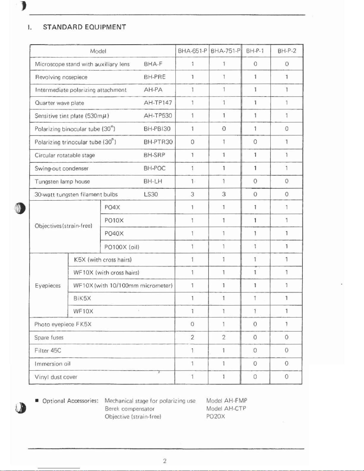
STANDARD
EQUIPMENT
Optional
Accessories:
Mechanical
stage
for
polarizing
use Model
AH-FMP
Berek
cornpensalor
Modsl
AH-CTP
Qhjectivc
(srrain-free)
P020X
Model
Microscope
stand
wrth
aux~lrary
lens
BHA-F
Rcvo
lving
nosepiece
RH-PRE
l~itermediate
polarizing
a~tachmenl
AH-PA
Quarter
wave
plate
AH-TPI47
BHA-751-P
J
1
1
BHA-651-P
1
1
1
1
pp
BH-P-1
I
0
1
I
1
Sensrt~ve
tint
plate
(53OrnpCI)
AH-TP530
Polarlztng
b~necular
tube
(30~)
BH-PB
130
Polari~lnq
tr~nocular
tube
(30~1
BH-PTH30
Circular
rotatable
stage
BH-SRP
Swing-out
condenser
BH
-POC
Tungsten
lamp
house
BH-LH
30-watt
tungsten
filament
bulbs
LS30
Objecrrves
(strain-free)
BH-P-2
0
1
1
1
1
0
1
1
1
3
1
1
PO4
X
POIOX
P040X
PO1
00X
Iollj
0
1
1
111
1
3
1
'
1
1
1
K5X
(with
cross
hatrs)
1
1-1
1
7
WFlOX
(with
cross
ha~rs}
1
1
1
1
Eyepieces
WF1
OX
(with
1011
00mm
micrometer)
1
BIKSX
1
1
1
1
WFlOX
1
1
11
1
1
1
1
1
1
1
Photo
~yep~ece
F
K5X
0
0
Spare
fuses
F~lter
45C
Immersion
nil
I
V~nyt
dust
cover
-
1
1
0
0
0
0
-
2
1
1
1
1
10
-
2
0
I
1
I0
1
0
'
,!
0
1
\
1
1
0
1
1
1
1
t
1
1
0
0
0
0
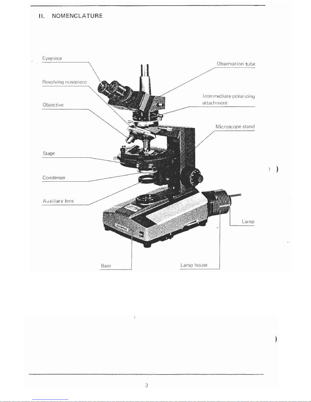
II.
NOMENCLATURE
Base
1
Ill.
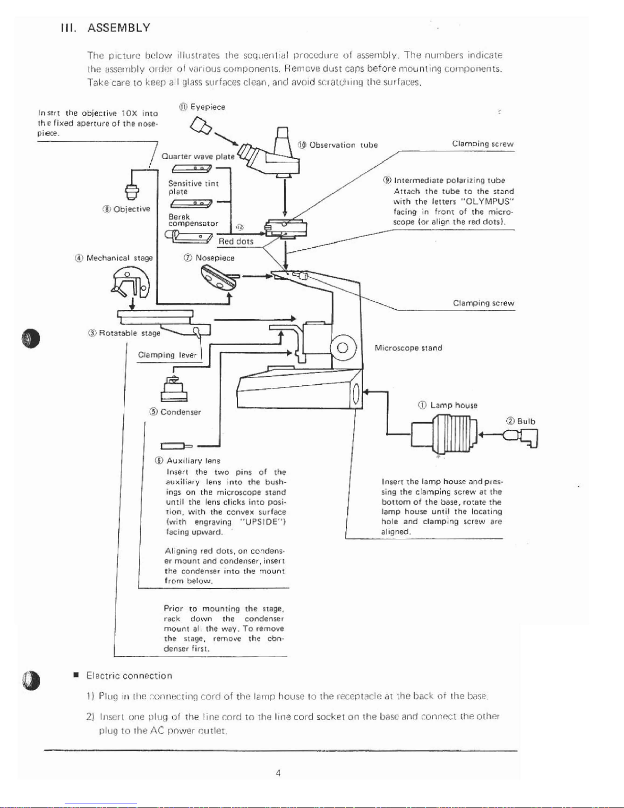
ASSEMBLY
Tfic
141ctl1re
i~clow 11111~t~atCs the
scq~leritidl
~prncodr~r
1%
ol
assernbly
T!ie
nt~nhrvc
~ndtcrlt~
the
assembly
cjrrlnr
ol
vilrlous
colnponenls. Rel~iove
dust
caps
before mounting
Lurnpunents.
Take
cars
lo
Ireep
all
glaqs
surfaces cleat),
and
avalcl
si.4
al~4t111g
tlie
srrr
faces.
0
Eyepiece
Insert
the
objective
10X
inlo
the
fixed
aperture
of
the
nose-
piece.
$1
Objective
"I
@
Qbservat~on
tu11e
Clamping
screw
Quarter
wave
plate
Sensitive
rint
@j
lntermedrate Dolarizing
tube
plate
Attach
the
tube
to
the
stand
--
wrth
rhe
letters
"OLYMPUS"
Berek
facing
in front
of
the
micro-
compensator
scope
(or
align
the
red
dots).
(TI
Mechanical
stage
I
0
Nosepiece
\
k---
Rotatable
stage
M~croscops
stand
@
Lamp
house
Insert
the
two
pins
01
the
aux~liary
lens ~nto
the
bush.
rng5 on
the
microscoae
stand
unt~l
the
lens
clicks
into
posi-
tion.
w~th
the
convex
surface
(with
engraving
"UPS1DE")
tac~ng
upward.
Align~ng
red dots,
on
condens-
er
mount
and
condenser,
Insert
the
condenser
inro
the
mount
Prior
to
mounting
the
stage.
rack
down
the
condenser
mount
all
the
way.
To
rernwe
the
stage,
(*move
rhe
cbn-
denser
firs[.
Insert
the
lamp
house
and
pres-
sing
the clamping
screw
at
the
bottom
of
the
base,
rotate
he
lamp
house
until
the
locating
hole
and
clamplng
screw
are
al~sned.
,
Electr~c
connection
1)
Pluq 111
11i(!
t:o~hnr?ct~ng
cord
of
th~
lari~p
hocrsc
10
~hc
r~ccptactr:
at
tho
back
of
the
bds~
2)
Inscr
i
onc
plz~g
ol
the
linc
cord
to
the
Illis
cord
socket
on
rhe
llasc
and
coiincct
the
orher
or lug
to
rhe
AC
[lnwer
outlet.
;
)
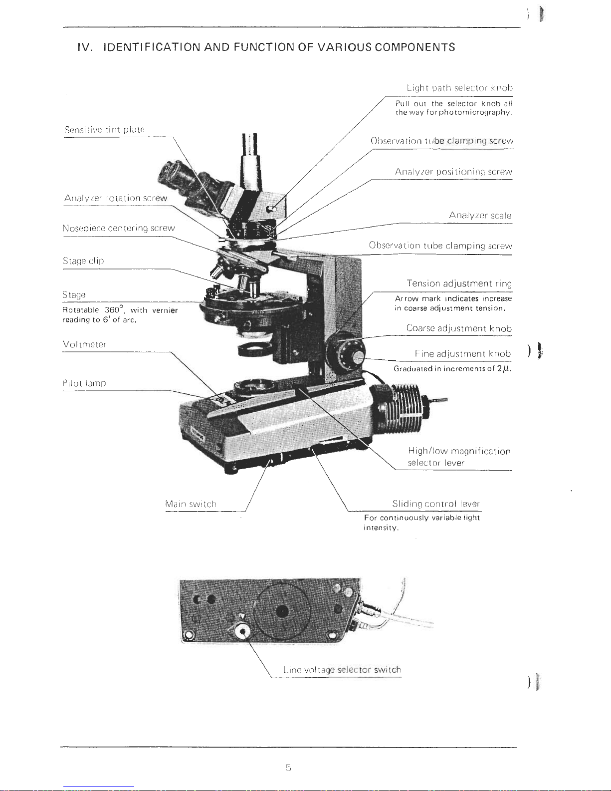
IV. IDENTIFICATION AND FUNCTION OF VARIOUS COMPONENTS
L~ght
path
selector
kr~ol)
/
Pull out the selector knob all
the way for photomicrography.
Analyicl- scaic
Tension adjustment ring
Arrow mark ~ndicates Increase
in coarse adjustment tension.
Voltmeter
\
SIlcIinq cont~~ol lever
For cont~nuously variable light
intensity.
\
L~ic vol~~g~
selector
switch
 Loading...