

Page 1

PF-650(B)
Option Copier
SERVICE MANUAL
Code Y110900-9
Page 2

PUBLICATION ISSUED BY:
Olivetti S.p.A.
77, Via Jervis - 10015 Ivrea (TO)
Italy
Copyright © 2009, Olivetti
All rights reserved
Page 3

CAUTION
RISK OF EXPLOSION IF BATTERY IS REPLACED BY AN INCORRECT TYPE. DISPOSE OF
USED BATTERIES ACCORDING TO THE INSTRUCTIONS.
It may be illegal to dispose of this battery into the municipal waste stream. Check with your local
solid waste officials for details in your area for proper disposal.
ATTENTION
IL Y A UN RISQUE D’EXPLOSION SI LA BATTERIE EST REMPLACEE PAR UN MODELE DE
TYPE INCORRECT. METTRE AU REBUT LES BATTERIES UTILISEES SELON LES INSTRUCTIONS DONNEES.
Il peut être illégal de jeter les batteries dans des eaux d’égout municipales. Vérifiez avec les fonctionnaires municipaux de votre région pour les détails concernant des déchets solides et une mise
au rebut appropriée.
Page 4

This page is intentionally left blank.
Page 5

Safety precautions
This booklet provides safety warnings and precautions for our service personnel to ensure the safety of
their customers, their machines as well as themselves during maintenance activities. Service personnel
are advised to read this booklet carefully to familiarize themselves with the warnings and precautions
described here before engaging in maintenance activities.
Page 6
Safety warnings and precautions
Various symbols are used to protect our service personnel and customers from physical danger and
to prevent damage to their property. These symbols are described below:
DANGER: High risk of serious bodily injury or death may result from insufficient attention to or incorrect
compliance with warning messages using this symbol.
WARNING: Serious bodily injury or death may result from insufficient attention to or incorrect compliance
with warning messages using this symbol.
CAUTION: Bodily injury or damage to property may result from insufficient attention to or incorrect
compliance with warning messages using this symbol.
Symbols
The triangle ( ) symbol indicates a warning including danger and caution. The specific point
of attention is shown inside the symbol.
General warning.
Warning of risk of electric shock.
Warning of high temperature.
indicates a prohibited action. The specific prohibition is shown inside the symbol.
General prohibited action.
Disassembly prohibited.
indicates that action is required. The specific action required is shown inside the symbol.
General action required.
Remove the power plug from the wall outlet.
Always ground the copier.
Page 7

1.Installation Precautions
WARNING
• Do not use a power supply with a voltage other than that specified. Avoid multiple connections to
one outlet: they may cause fire or electric shock. When using an extension cable, always check
that it is adequate for the rated current. .............................................................................................
• Connect the ground wire to a suitable grounding point. Not grounding the copier may cause fire or
electric shock. Connecting the earth wire to an object not approved for the purpose may cause
explosion or electric shock. Never connect the ground cable to any of the following: gas pipes,
lightning rods, ground cables for telephone lines and water pipes or faucets not approved by the
proper authorities. ............................................................................................................................
CAUTION:
• Do not place the copier on an infirm or angled surface: the copier may tip over, causing injury. .......
• Do not install the copier in a humid or dusty place. This may cause fire or electric shock. ................
• Do not install the copier near a radiator, heater, other heat source or near flammable material.
This may cause fire. .........................................................................................................................
• Allow sufficient space around the copier to allow the ventilation grills to keep the machine as cool
as possible. Insufficient ventilation may cause heat buildup and poor copying performance. ...........
• Always handle the machine by the correct locations when moving it. ...............................................
• Always use anti-toppling and locking devices on copiers so equipped. Failure to do this may cause
the copier to move unexpectedly or topple, leading to injury. ...........................................................
• Avoid inhaling toner or developer excessively. Protect the eyes. If toner or developer is accidentally ingested, drink a lot of water to dilute it in the stomach and obtain medical attention immediately. If it gets into the eyes, rinse immediately with copious amounts of water and obtain medical
attention. ......................................................................................................................................
• Advice customers that they must always follow the safety warnings and precautions in the copier’s
instruction handbook. .....................................................................................................................
Page 8
2.Precautions for Maintenance
WARNING
• Always remove the power plug from the wall outlet before starting machine disassembly. ...............
• Always follow the procedures for maintenance described in the service manual and other related
brochures. .......................................................................................................................................
• Under no circumstances attempt to bypass or disable safety features including safety mechanisms
and protective circuits. .....................................................................................................................
• Always use parts having the correct specifications. ..........................................................................
• Always use the thermostat or thermal fuse specified in the service manual or other related brochure when replacing them. Using a piece of wire, for example, could lead to fire or other serious
accident. ..........................................................................................................................................
• When the service manual or other serious brochure specifies a distance or gap for installation of a
part, always use the correct scale and measure carefully. ................................................................
• Always check that the copier is correctly connected to an outlet with a ground connection. .............
• Check that the power cable covering is free of damage. Check that the power plug is dust-free. If it
is dirty, clean it to remove the risk of fire or electric shock. ..............................................................
• Never attempt to disassemble the optical unit in machines using lasers. Leaking laser light may
damage eyesight. ...........................................................................................................................
• Handle the charger sections with care. They are charged to high potentials and may cause electric
shock if handled improperly. ............................................................................................................
CAUTION
• Wear safe clothing. If wearing loose clothing or accessories such as ties, make sure they are
safely secured so they will not be caught in rotating sections. ..........................................................
• Use utmost caution when working on a powered machine. Keep away from chains and belts. ........
• Handle the fixing section with care to avoid burns as it can be extremely hot. ..................................
• Check that the fixing unit thermistor, heat and press rollers are clean. Dirt on them can cause
abnormally high temperatures. ........................................................................................................
Page 9
• Do not remove the ozone filter, if any, from the copier except for routine replacement. ....................
• Do not pull on the AC power cord or connector wires on high-voltage components when removing
them; always hold the plug itself. .....................................................................................................
• Do not route the power cable where it may be stood on or trapped. If necessary, protect it with a
cable cover or other appropriate item. .............................................................................................
• Treat the ends of the wire carefully when installing a new charger wire to avoid electric leaks. ........
• Remove toner completely from electronic components. ...................................................................
• Run wire harnesses carefully so that wires will not be trapped or damaged. ....................................
• After maintenance, always check that all the parts, screws, connectors and wires that were
removed, have been refitted correctly. Special attention should be paid to any forgotten connector,
trapped wire and missing screws. ...................................................................................................
• Check that all the caution labels that should be present on the machine according to the instruction
handbook are clean and not peeling. Replace with new ones if necessary. ......................................
• Handle greases and solvents with care by following the instructions below: .....................................
· Use only a small amount of solvent at a time, being careful not to spill. Wipe spills off completely.
· Ventilate the room well while using grease or solvents.
· Allow applied solvents to evaporate completely before refitting the covers or turning the power
switch on.
· Always wash hands afterwards.
• Never dispose of toner or toner bottles in fire. Toner may cause sparks when exposed directly to
fire in a furnace, etc. .......................................................................................................................
• Should smoke be seen coming from the copier, remove the power plug from the wall outlet imme-
diately. ............................................................................................................................................
3.Miscellaneous
WARNING
• Never attempt to heat the drum or expose it to any organic solvents such as alcohol, other than the
specified refiner; it may generate toxic gas. .....................................................................................
Page 10

This page is intentionally left blank.
Page 11

3MV
CONTENTS
1-1 Specifications
1-1-1 Specifications..........................................................................................................................................1-1-1
1-1-2 Parts names............................................................................................................................................1-1-2
1-1-3 Machine cross section ............................................................................................................................1-1-3
1-2 Installation
1-2-1 Installation environment ..........................................................................................................................1-2-1
1-2-2 Unpacking ...............................................................................................................................................1-2-2
(1) Unpacking .........................................................................................................................................1-2-2
(2) Removing tapes and spacers............................................................................................................1-2-3
1-3 Maintenance mode
1-3-1 Maintenance mode .................................................................................................................................1-3-1
(1) Executing a maintenance item ..........................................................................................................1-3-1
(2) Contents of the maintenance mode items .........................................................................................1-3-2
1-4 Troubleshooting
1-4-1 Paper misfeed detection .........................................................................................................................1-4-1
(1) Paper misfeed detection....................................................................................................................1-4-1
(2) Paper misfeed detection condition ....................................................................................................1-4-1
(3) Paper misfeeds .................................................................................................................................1-4-2
1-4-2 Self-diagnosis .........................................................................................................................................1-4-3
(1) Self-diagnostic function .....................................................................................................................1-4-3
(2) Self diagnostic code ..........................................................................................................................1-4-3
1-4-3 Electrical problem ...................................................................................................................................1-4-5
1-5 Assembly and Disassembly
1-5-1 Precautions for assembly and disassembly............................................................................................1-5-1
(1) Precautions .......................................................................................................................................1-5-1
1-5-2 Procedure for assembly and disassembly ..............................................................................................1-5-2
(1) Adjusting the center line ....................................................................................................................1-5-2
2-1 Mechanical construction
2-1-1 Mechanical construction .........................................................................................................................2-1-1
2-2 Electrical Parts Layout
2-2-1 Electrical parts layout..............................................................................................................................2-2-1
(1) PWBs, motors and clutches ..............................................................................................................2-2-1
(2) Switches ............................................................................................................................................2-2-2
2-3 Operation of the PWBs
2-3-1 Side feeder main PWB............................................................................................................................2-3-1
2-4 Appendixes
Maintenance parts list .............................................................................................................................2-4-1
Periodic maintenance procedures ..........................................................................................................2-4-2
Wiring diagram........................................................................................................................................2-4-3
Page 12

3MV
This page is intentionally left blank.
Page 13

3MV
1-1-1
1-1 Specifications
1-1-1 Specifications
Paper capacity ................................ 4000 sheets (80 g/m2)
Paper size.......................................A4, B5, 11 × 8 1/2"
Paper weight...................................60 to 160 g/m
2
Paper type ......................................Plain, recycled and colored paper
Power source..................................Electrically connected to the machine
Dimensions .....................................371 (W) × 589 (D) × 693 (H) mm
14 5/8" (W) × 23 3/16" (D) × 27 5/16" (H)
Weight.............................................41 kg or less/90.2 lbs. or less
NOTE: These specifications are subject to change without notice.
Y110900-9 Service Manual
Page 14
3MV
1-1-2
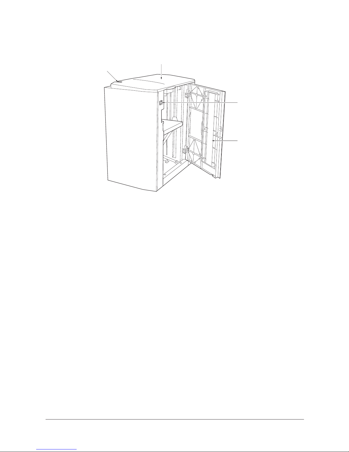
1-1-2 Parts names
Figure 1-1-1 Parts names
1
4
3
2
1. Upper cover
2. Right cover
3. Right down switch
4. Side feeder release button
Service Manual Y110900-9
Page 15
3MV
1-1-3
1-1-3 Machine cross section
Figure 1-1-2 Cross section
Figure 1-1-3
Papaer path
Y110900-9 Service Manual
Page 16

3MV
1-1-4
This page is intentionally left blank.
Service Manual Y110900-9
Page 17

3MV
1-2-1
1-2Installation
1-2-1 Installation environment
Installation location (Be based on the machine establishment place.)
Avoid direct sunlight or bright lighting. Ensure that the photo-conductor will not be exposed to direct sunlight or other
strong light when removing paper jams.
Avoid extremes of temperature and humidity, abrupt ambient temperature changes, and hot or cold air directed onto the
machine.
Avoid dust and vibration.
Choose a surface capable of supporting the weight of the machine.
Place the machine on a level surface (maximum allowance inclination: 1°).
Avoid air-borne substances that may adversely affect the machine or degrade the photo-conductor, such as mercury,
acidic of alkaline vapors, inorganic gasses, NOx, SOx gases and chlorine-based organic solvents.
Select a room with good ventilation.
Y110900-9 Service Manual
Page 18

3MV
1-2-2
1-2-2 Unpacking
(1) Unpacking
Figure 1-2-1 Unpacking
Caution: Place the machine on a level surface. See the Installation Guide for installation.
(1) Side feeder
(2) Guide plate
(3) Switch contact plate
(4) M4 × 12 dish screw
(5) M3 × 6 Tap Tight S screw
(6) M4 × 6 TP screws
(7) Clamp
(8) Plastic bag (70 × 110 mm)
(9) Air padded bag (400 × 500 mm)
(10) Bottom pad
(11) Top pad
(12) Lift spacer
(13) Installation guide
(14) Plastic bag
(15) Machine cover
(16) Outer case
(17) Bar code labels
(18) Skids
(19) Joint hinges
(20) Inner frame
Service Manual Y110900-9
Page 19

3MV
1-2-3
(2) Removing tapes and spacers
Remove the tapes and spacers as follows before machine installation.
1. Remove the tape securing the hook.
2. Remove two tapes and then remove the
sheet.
3. Remove two tapes securing the signal cable
and base retainer.
4. Remove two tapes and then remove the air
padded bag.
Figure 1-2-2
5. Remove two tapes securing the upper and
right covers.
Figure 1-2-3
A
ir padded
bag
Ta pe s
Signal cable
Base retainer
Ta pe s
Ta pe
Ta pe
Ta pe
Sheet
Hook
Right cove
r
Upper cover
Ta pe
Ta pe
Y110900-9 Service Manual
Page 20

3MV
1-2-4
6. Open the upper cover.
7. Remove the tape securing each of the two
lift spacers and then the spacers.
8. Remove the paper on the lift plate.
Figure 1-2-4
9. Open the right cover.
10. Remove two screws and then remove the
feeder support.
Figure 1-2-5
Lift spacer
Paper
Upper cover
Ta pe
Lift spacer
Ta pe
Screw
Screw
Right cove
r
Feeder support
Service Manual Y110900-9
Page 21

3MV
1-3-1
1-3Maintenance mode
1-3-1 Maintenance mode
(1) Executing a maintenance item
Enter “10871087” using
the numeric keys.
Enter “001” using the cursor
up/down keys or numeric keys
and press the start key.
Enter the maintenance item
number using the cursor up/down keys
or numeric keys.
The selected maintenance item is run.
Press the stop/clear key.
Press the start key.
Start
End
Maintenance mode is entered.
The maintenance item is
selected.
Maintenance mode is exited.
Repeat the same
maintenance item?
Run another maintenance
item?
No
No
Yes
Yes
Y110900-9 Service Manual
Page 22

3MV
1-3-2
(2) Contents of the maintenance mode items
Maintenance
item No.
Description
U019
Displaying the ROM version
Description
Displays the part number for the ROM fitted to each PWB.
Purpose
To check the part number or to decide, based on the last digit of the number, if the newest version of ROM is
installed.
Method
1. Press the start key. The ROM version (the last 6 digits of the part number) is displayed.
2. Change the screen using the * or # keys.
Completion
Press the stop/clear key. The screen for selecting a maintenance item No. is displayed.
Display Description
MAIN Main PWB ROM IC
ENGINE Engine PWB ROM IC
SCANNER Scanner PWB ROM IC
LANGUAGE (Stand.) Standard language ROM IC
LANGUAGE(Option) Optional language ROM IC
MAIN BOOT Main PWB booting
PRINTER Optional printer board booting
NETWORK SCANNER Optional network scanner ROM IC
DP DP ROM IC
FINISHER Optional document finisher main PWB ROM IC
ENGINE BOOT Engine PWB booting
FINISHER BOOT Optional document finisher main PWB booting
CASSETTE1 Deck PWB ROM IC
CASSETTE2 Cassette PWB ROM IC
DUPLEX Duplex PWB ROM IC
SIDE FEEDER Side feeder main PWB ROM IC
Service Manual Y110900-9
Page 23

3MV
1-3-3
U031
Checking switches for paper conveying
Description
Displays the ON/OFF status of each paper detection switch on the paper conveying path.
Purpose
To check the operation of the switches for paper conveying.
Method
1. Press the start key. A list of switches, the on-off status of which can be checked, are displayed.
2. Turn each switch on and off manually to check the status.
When the on-status of a switch is detected, that switch is displayed in reverse.
*Optional.
Completion
Press the stop/clear key. The screen for selecting a maintenance item No. is displayed.
Maintenance
item No.
Description
Display Sensor
REG SW Registration switch (RSW)
FEED-A SW Feed switch 1 (FSW1)
FEED-B SW E Feed switch 2 (FSW2)
FD EJ SW Switchback exit switch (SBESW)
EJECT SW Exit switch (ESW)
FEED-B SW D Feed switch 2 (FSW2)
LCF SW A Deck conveying switch 1 (DKCSW1)
LCF SW B Deck conveying switch 2 (DKCSW2)
FEED-C SW Feed switch 3 (FSW3)
FEED-D SW Feed switch 4 (FSW4)
FEED-E SW Feed switch 5 (FSW5)
LDECK FD SW Side feeder feed switch (SFFSW)*
FS SW Feedshift switch (FSSW)
DUP JAM SW Duplex jam detection switch (DUPJSW)
DUP FEED SW Duplex feed switch (DUPFSW)
DUP CV SW A Duplex conveying switch 1 (DUPCSW1)
DUP CV SW B Duplex conveying switch 2 (DUPCSW2)
DUP CV SW C Duplex conveying switch 3 (DUPCSW3)
PE SW1 Paper empty switch 1 (PESW1)
PE SW2 Paper empty switch 2 (PESW2)
PE SW3 Paper empty switch 3 (PESW3)
PE SW4 Paper empty switch 4 (PESW4)
LDECK PE SW Side feeder paper empty switch (SFPESW)*
LIM SW1 Lift limit switch 1 (LILSW1)
LIM SW2 Lift limit switch 2 (LILSW2)
LIM SW3 Lift limit switch 3 (LILSW3)
LIM SW4 Lift limit switch 4 (LILSW4)
LCF-A-1 SW Timing switch 1 (TIMSW1)
FEED-D-1 SW Timing switch 2 (TIMSW2)
FEED-E-1 SW Timing switch 3 (TIMSW3)
Y110900-9 Service Manual
Page 24

3MV
1-3-4
U208
Setting the paper size for the side feeder
Description
Sets the sizes of paper placed in cassette1, cassette 2 and side feeder respectively.
Purpose
To set the size when the size of paper placed in cassette 1, cassette 2 or side feeder is changed.
Setting: Paper size for cassettes 1 and 2, and the side feeder
1. Press the start key.
2. Select paper size.
Cassette 1, 2: 11 x 8.5, A4, B5 or 16K
Side feeder: 11 x 8.5, A4 or B5
Initial setting: A4 (220-240 V specifications)/11 x 8.5 (120 V specifications)
3. Press the start key. The setting is set.
Setting: Paper size for the large size side feeder
1. Press the start key.
2. Select SIDE FEEDER.
3. Select paper size.
Side feeder: 11 x 17, 8.5 x 14, 11 x 8.5, 8.5 x 11, A3, A4, or A4R
Initial setting: A4 (220-240 V specifications)/8.5 x 11 (120 V specifications)
4. Press the start key. The setting is set.
Completion
To exit this maintenance item without changing the current setting, press the stop/clear key. The screen for
selecting a maintenance item No. is displayed.
U212
Setting the feeder lift operation
Description
Sets the operation of the side feeder lift motor for when paper in the side feeder is exhausted.
Purpose
To be set according to the paper loading method.
Method
Press the start key. The screen for selecting an item is displayed.
Setting
1. Select the method to load paper.
Initial setting: SIDE FEED
2. Press the start key. The setting is set.
Completion
Press the stop/clear key. The screen for selecting a maintenance item No. is displayed.
Maintenance
item No.
Description
Display Description
SIDE FEED Load paper through the right cover
UPPER FEED Load paper through the upper cover
Service Manual Y110900-9
Page 25

3MV
1-3-5
U247
Setting the paper feed device
Description
Drives each motor of the side feeder.
Purpose
To check the operation of the side feeder.
Method
1. Press the start key. The screen for selecting an item is displayed.
2. Select the motor to be operated.
When checking the side feeder lift motor (SFLM) operation, set the paper to the side feeder.
The selected item is displayed.
Side feeder
Large size side feeder
3. To stop operation, press the stop/clear key.
If this maintenance item is executed with the upper cover of the side feeder open, detection of the upper
limit is not possible and thus the side feeder lift motor overruns.
Completion
Press the stop key after operation stops. The screen for selecting a maintenance item No. is displayed.
U327
Setting the drawer heater ON/OFF
Description
Sets ON/OFF of the drawer heater and optional side feeder dehumidifier.
Purpose
To change the setting when dew condensation on the drum is heavy.
Method
Press the start key. The screen for selecting an item is displayed.
Setting
1. Select ON or OFF. The selected item is displayed in reverse.
Initial setting: Drawer heater OFF, side feeder dehumidifier OFF
2. Press the start key. The setting is set, and the screen for selecting a maintenance item No. is displayed.
Completion
To exit this maintenance item without changing the current setting, press the stop/clear key. The screen for
selecting a maintenance item No. is displayed.
Maintenance
item No.
Description
Display Operation
SDECK MOT Side feeder drive motor (SFDM)
SDECK FAN Separation fan motor (SPFM) and suction fan motor (IFM)
SDECK LIFT Side feeder lift motor (SFLM)
SDECK CVCL Side feeder conveying clutch (SFCCL)
SDECK FDCL Side feeder paper feed clutch (SFPFCL)
Display Operation
FEED MOT H Side feeder paper feed motor (SFPFM) is turned on at high speed
FEED MOT L Side feeder paper feed motor (SFPFM) is turned on at low speed
CONV MOT H Side feeder paper conveying motor (SFPCM) is turned on at high
CONV MOT L Side feeder paper conveying motor (SFPCM) is turned on at low
LIFT UP-DOWN Side feeder lift motor (SFLM)
Display Description
CASSETTE ON Drawer heater ON
CASSETTE OFF Drawer heater OFF
SIDE FEEDER ON Side feeder dehumidifier heater ON
SIDE FEEDER OFF Side feeder dehumidifier heater OFF
Y110900-9 Service Manual
Page 26

3MV
1-3-6
U901
Checking/clearing copy counts by paper feed locations
Description
Displays or clears copy counts by paper feed locations.
Purpose
To check the time to replace consumable parts. Also to clear the counts after replacing the consumable parts.
Method
1. Press the start key. The counts by paper feed locations are displayed.
When an optional paper feed device is not installed, the corresponding count is not displayed.
Clearing
1. Select the count to be cleared. The selected item is displayed in reverse.
To clear the counts for all paper feed locations, press the reset key.
2. Press the start key. The count is cleared.
When clearing all counts, the screen for selecting a maintenance item No. is displayed.
Completion
To exit this maintenance item without changing the count, press the stop/clear key.
The screen for selecting a maintenance item No. is displayed.
Maintenance
item No.
Description
Display Paper feed locations
BYPASS MP tray
CASSETTE 1 Cassette 1
CASSETTE 2 Cassette 2
CASSETTE 3 Cassette 3
CASSETTE 4 Cassette 4
SIDE FEEDER Side feeder
DUPLEX Duplex unit
Service Manual Y110900-9
Page 27

3MV
1-3-7
U905
Checking/clearing counts by optional devices
Description
Displays or clears the counts of the DP, document finisher or side feeder.
Purpose
To check the use of the DP, document finisher and side feeder. Also to clear the counts after replacing consumable parts.
Method
1. Press the start key. The screen for selecting an item is displayed.
2. Select the device, the count of which is to be checked. The count of the selected device is displayed.
DP
Document finisher
Side feeder
Clearing
1. Select the item to be cleared. The selected item is displayed in reverse.
To clear the counts for all, press the reset key.
2. Press the start key. The count is cleared.
To return to the screen for selecting an item, press the stop/clear key.
Completion
Press the stop/clear key at the screen for selecting an item.
The screen for selecting a maintenance item No. is displayed.
Maintenance
item No.
Description
Display Description
DP Document processor
FINISHER Ducument finisher
FEEDER Side feeder
Display Description
ADP Number of single-sided originals that has passed through the DP
RADP Number of double-sided originals that has passed through the DP
Display Description
CP CNT Number of copies that has passed
STAPLE Frequency the stapler has been activated
PUNCH Frequency the punch has been activated
STACK Frequency the stacker has been activated
SADDLE Frequency the center holding has been activated
Display Description
LCT COUNTER Number of copies that has passed through the side feeder
Y110900-9 Service Manual
Page 28

3MV
1-3-8
This page is intentionally left blank.
Service Manual Y110900-9
Page 29

3MV
1-4-1
1-4 Troubleshooting
1-4-1 Paper misfeed detection
(1) Paper misfeed detection
When a paper jam occurs, the machine stops operating immediately. The machine operation panel shows a jam message
and the jam location. To remove the jammed paper, detach the side feeder from the machine.
Figure 1-4-1
(2) Paper misfeed detection condition
Section Jam code Description Conditions
Side feeder 14 No paper feed from side
feeder
Side feeder feed switch (SFFSW) does not turn on within 2000
ms of the side feeder drive motor (SFDM) turning on.
30 Multiple sheets in side
feeder paper feed section
Side feeder feed switch (SFFSW) does not turn off within 700
ms of its turning on.
32 Misfeed in registration Feed switch 1 (FSW1) does not turn on within specified time
(909 ms for 82 cpm/1170 ms for 62 cpm) of side feeder feed
switch (SFFSW) turning on.
SFFSW
SFPFCL
Y110900-9 Service Manual
Page 30

3MV
1-4-2
(3) Paper misfeeds
Problem
Causes/check procedures
Corrective measures
(1)
A paper jam in the
paper feed section is
indicated during
copying (no paper
feed from side
feeder).
Jam code 14
Broken side feeder feed
switch actuator.
Check visually and replace the side feeder feed switch if its actuator is broken.
Defective side feeder feed
switch.
Run maintenance item U031 and turn the side feeder feed switch
on and off manually. Replace the side feeder feed switch if indication of the corresponding sensor on the touch panel is not displayed in reverse.
Check if the side feeder
drive motor malfunctions.
Run maintenance item U247 and select the side feeder drive
motor on the touch panel to be turned on and off. Check the status
and remedy if necessary.
Electrical problem with the
side feeder drive motor.
Check.
(2)
A paper jam in the
paper feed section is
indicated during
copying (multiple
sheets in side
feeder).
Jam code 30
Broken side feeder feed
switch actuator.
Check visually and replace the side feeder feed switch if its actuator is broken.
Defective side feeder feed
switch.
Run maintenance item U031 and turn the side feeder feed switch
on and off manually. Replace the side feeder feed switch if indication of the corresponding sensor on the touch panel is not displayed in reverse.
Check if the side feeder
drive motor malfunctions.
Run maintenance item U247 and select the side feeder drive
motor on the touch panel to be turned on and off. Check the status
and remedy if necessary.
Electrical problem with the
side feeder drive motor.
Check.
(3)
A paper jam in the
paper conveying section is indicated during copying (jam in
registration/transfer
section).
Jam code 32
Defective feed switch 1. Run maintenance item U031 and turn feed switch 1 on and off
manually. Replace feed switch 1 if indication of the corresponding
sensor on the touch panel is not displayed in reverse.
Broken side feeder feed
switch actuator.
Check visually and replace the side feeder feed switch if its actuator is broken.
Defective side feeder feed
switch.
Run maintenance item U031 and turn the side feeder feed switch
on and off manually. Replace the side feeder feed switch if indication of the corresponding sensor on the touch panel is not displayed in reverse.
The vertical feed roller or
feed B roller is dirty with
paper powder.
Check and, if it is dirty, clean it.
The vertical feed roller or
feed B roller is deformed or
worn.
Check and, if it is deformed or worn, fix or replace it.
Service Manual Y110900-9
Page 31

3MV
1-4-3
1-4-2 Self-diagnosis
(1) Self-diagnostic function
When a problem is detected in the side feeder, copying is disabled and the machine operation section displays a code
consisting of “C” followed by a number, indicating the nature of the problem.
After removing the problem, the self-diagnostic function can be reset by reattaching the side feeder.
(2) Self diagnostic code
Code Contents
Remarks
Causes Check procedures/corrective measures
C0420 Side feeder communication error
• A communication error from side
feeder is detected 10 times in succession.
Poor contact in the
connector terminals.
Check the connection of connector YC15 on
the engine PWB and the connector YC3 on
the side feeder main PWB, and the continuity across the connector terminals. Repair or
replace if necessary.
Defective engine
PWB.
Replace the engine PWB.
Defective side
feeder main PWB.
Replace the side feeder main PWB.
C0700 Side feeder EEPROM error
• An error occurs in EEPROM (U4) data
read or write for the side feeder main
PWB.
Defective side
feeder main PWB.
Replace the side feeder main PWB.
C1140 Side feeder lift motor going up error
(optional side feeder)
• Upper limit detection switch does not
turn off within 15 s of the side feeder
lift motor starting (within 200 ms during
paper feeding). This error is detected
four times successively.
Poor contact of
upper limit detection switch connector terminals.
Reinsert the connector. Also check for continuity within the connector cable. If none,
repair or replace the cable.
Defective side
feeder main PWB.
Replace the side feeder main PWB.
Defective side
feeder lift motor.
Run maintenance mode U247 and measure
the voltage between terminals YC5-A12
(side feeder main circuit board) and YC6B11. (Make sure all of LUSSW, UCSSW,
LLSSW and RCSSW are off.)
Despite either DC24V or DC-24V is
observed but if the side feeder lift motor
does not operate, replace the side feeder lift
motor.
Y110900-9 Service Manual
Page 32

3MV
1-4-4
C1150 Side feeder lift motor going down
error (optional side feeder)
• Lower limit detection switch does not
turn off within 15 s of the side feeder
lift motor starting (within 200 ms during
paper feeding). This error is detected
four times successively.
Poor contact of
lower limit detection switch connector terminals.
Reinsert the connector. Also check for continuity within the connector cable. If none,
repair or replace the cable.
Defective side
feeder main PWB.
Replace the side feeder main PWB.
Defective side
feeder lift motor.
Run maintenance mode U247 and measure
the voltage between terminals YC5-A12
(side-feeder main circuit board) and YC6B11. (Make sure all of LUSSW, UCSSW,
LLSSW and RCSSW are off.)
Despite either DC24V or DC-24V is
observed but if the side-feeder lift motor
does not operate, replace the side-feeder lift
motor.
C2640 Side feeder drive motor error Overloaded side
feeder drive motor
Verify that the side feeder motor or the paper
feeding mechanism is not interrupted by any
objects.
Defective side
feeder drive motor.
Replace the side feeder drive motor.
Defective side
feeder main PWB.
Replace the side feeder main PWB.
Code Contents
Remarks
Causes Check procedures/corrective measures
Service Manual Y110900-9
Page 33

3MV
1-4-5
1-4-3 Electrical problem
Problem Causes Check procedures/corrective measures
(1)
The side feeder
paper feed clutch
does not operate.
Poor contact of the side
feeder paper feed clutch
connector terminals.
Reinsert the connector. Also check for continuity within the connector cable. If none, remedy or replace the cable.
Broken side feeder paper
feed clutch coil.
Check for continuity across the coil. If none, replace the side
feeder paper feed clutch.
Defective side feeder paper
feed clutch.
Run maintenance item U247 and check if the side feeder paper
feed clutch does not operate when YC5-A10 on the side feeder
main PWB goes low. If so, replace the side feeder paper feed
clutch.
Defective side feeder main
PWB.
Run maintenance item U247 and check if YC5-A10 on the side
feeder main PWB goes low. If not, replace the side feeder main
PWB.
(2)
The side feeder
paper conveying
clutch does not operate.
Poor contact of the side
feeder paper conveying
clutch connector terminals.
Reinsert the connector. Also check for continuity within the connector cable. If none, remedy or replace the cable.
Broken side feeder paper
conveying clutch coil.
Check for continuity across the coil. If none, replace the side
feeder paper conveying clutch.
Defective side feeder paper
conveying clutch.
Run maintenance item U247 and check if the side feeder paper
conveying clutch does not operate when YC6-B7 on the side
feeder main PWB goes low. If so, replace the side feeder paper
conveying clutch.
Defective side feeder main
PWB.
Run maintenance item U247 and check if YC6-B7 on the side
feeder main PWB goes low. If not, replace the side feeder main
PWB.
(3)
The separation fan
motor does not operate.
Poor contact of the separation fan motor connector
terminals.
Reinsert the connector. Also check for continuity within the connector cable. If none, remedy or replace the cable.
Defective separation fan
motor.
Run maintenance item U247 and check if the separation fan
motor does not operate when YC6-A1 on the side feeder main
PWB goes low. If so, replace the separation fan motor.
Defective side feeder main
PWB.
Run maintenance item U247 and check if YC6-A1 on the side
feeder main PWB goes low. If not, replace the side feeder main
PWB.
(4)
The suction fan
motor does not operate.
Poor contact of the suction
fan motor connector termi
-
nals.
Reinsert the connector. Also check for continuity within the connector cable. If none, remedy or replace the cable.
Defective suction fan motor. Run maintenance item U247 and check if the suction fan motor
does not operate when YC6-A2 on the side feeder main PWB
goes low. If so, replace the side feeder main PWB.)
Defective side feeder main
PWB.
Run maintenance item U247 and check if YC6-A2 on the side
feeder main PWB goes low. If not, replace the side feeder main
PWB.
Y110900-9 Service Manual
Page 34

3MV
1-4-6
(5)
The side feeder lift
motor does not operate.
Poor contact of the side
feeder lift motor connector
terminals.
Reinsert the connector. Also check for continuity within the connector cable. If none, remedy or replace the cable.
Broken side feeder lift
motor coil.
Check for continuity across the coil. If none, replace the feeder lift
motor.
Defective side feeder lift
motor or side feeder main
PWB.
Run maintenance item U247 and measure the voltage between
side feeder main PWB terminal YC5-A12 and YC6-B11.
Each of LUSSW, UCSSW, LLSSW, and RCSSW should be turned
off.
Although 24 V DC or -24 V DC are measured, if a side feeder lift
motor does not operate, replace the side feeder lift motor.
When change of voltage is not measured, (0V), replace the side
feeder main PWB.
(6)
The side feeder drive
motor does not operate.
Poor contact of the side
feeder drive motor connector terminals.
Reinsert the connector. Also check for continuity within the connector cable. If none, remedy or replace the cable.
Broken side feeder drive
motor coil.
Check for continuity across the coil. If none, replace the feeder lift
motor.
Defective side feeder drive
motor.
Run maintenance item U247 and check if the side feeder drive
motor does not operate when YC4-4 on the side feeder main
PWB goes low. If so, replace the side feeder drive motor.
Defective side feeder main
PWB.
Run maintenance item U247 and check if YC6-A1 on the side
feeder main PWB goes low. If not, replace the side feeder main
PWB.
Problem Causes Check procedures/corrective measures
24V DC
SFMPWB
GND
Fwd./
rev.
motor
driver
SFLM+
SFLM-
ULSSW
UCSSW
RCSSW
LLSSW
YC6-B11
YC5-A12
SFLM
SFLM Wiring Diagram
C
P
U
Off
Off
Off
Off
On
On
On
On
GND
GND
24V DC
24V DC
Service Manual Y110900-9
Page 35

3MV
1-5-1
1-5 Assembly and Disassem bly
1-5-1 Precautions for assembly and disassembly
(1) Precautions
Before starting disassembly, press the Power key on the operation panel to off. Make sure that the Power lamp is off
before turning off the main power switch. And then unplug the power cable from the wall outlet. Turning off the main power
switch before pressing the Power key to off may cause damage to the equipped hard disk.
When handling PWBs (printed wiring boards), do not touch parts with bare hands. The PWBs are susceptible to static
charge.
Do not touch any PWB containing ICs with bare hands or any object prone to static charge.
When removing the hook of the connector, be sure to release the hook.
Take care not to get the cables caught.
To reassemble the parts, use the original screws. If the types and the sizes of screws are not known, refer to the PARTS
LIST.
Y110900-9 Service Manual
Page 36

3MV
1-5-2
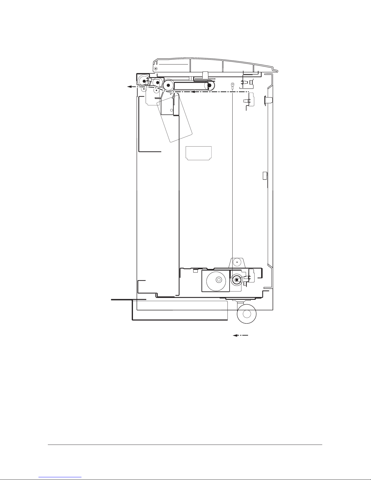
1-5-2 Procedure for assembly and disassembly
(1) Adjusting the center line
Make the following adjustment if there is a regular error between the center lines of the original and the copy image when
paper is fed from the side feeder.
Note: Before performing this adjustment, be sure to perform the center line adjustment of the machine.
<Procedure>
1. Run maintenance item U034 and output a
test pattern.
2. Measure the discrepancy L (mm) between
the center lines of the paper and test pattern.
3. Open the lower vertical conveying cover of
the machine. Loosen the two screws securing the feeder retainer and move the Vshaped groove on the feeder retainer by the
measured amount L and retighten the
screws.
* If the center line of the sample is shifted to
the paper front, move the V-shaped groove
of the feeder retainer toward the machine
front (example 1).
* If the center line of the sample is shifted to
the paper rear, move the V-shaped groove
of the feeder retainer toward the machine
rear (example 2).
Figure 1-5-1
Figure 1-5-2
Screw
Feeder retainer
Feeder retainer
V-shaped groove
Screw
Vertical
conveying
cover
Scale
Sample 1
Sample 2
L
L
Center of pape
r
Eject
Eject
Center of test
pattern
Center of pape
r
Center of test
pattern
Service Manual Y110900-9
Page 37

3MV
2-1-1
2-1 Mechanical construction
2-1-1 Mechanical construction
The side feeder consists of the paper lifting mechanism, which winds up paper with the wire of the side feeder lift motor
(SFLM), and the paper feed and conveying mechanism, which conveys paper with the drive of the paper conveying belt,
feed roller and left feed roller.
The side feeder lift motor (SFLM) raises the lift by winding up the wire engaged with the pulley. The lift is stopped at the
upper and lower limit by the control of the upper limit detection switch (ULPSW) and lower limit detection switch (LLPSW).
Paper is fed by controlling currents of air. The top sheet of the paper loaded on the lift is floated by the separation fan
motor (SPFM) and then induced onto the paper conveying belt by the suction fan motor (IFM). The sheet thus attracted to
the paper conveying belt is then conveyed to the feed roller and left feed roller by the drive of the side feeder drive motor
(SFDM).
Figure 2-1-1 Side feeder (1)
(1) Upper paper conveying guide
(2) Lower paper conveying guide
(3) Paper guide
(4) Paper conveying belt retainer
(5) Left side feeder guide
(6) Upper limit switch mount
(7) Switch cover
(8) Paper level detection switch mount
(9) Lower separation duct mount
(10) Lower suction duct
(11) Upper separation duct
(12) Upper suction duct
(13) Left feed roller
(14) Feed roller
(15) Paper conveying pulley
(16) Paper conveying belt pulley
(17) Paper conveying belt
(18) Side feeder paper conveying clutch
(SFCCL)
(19) Side feeder paper feed clutch (SFPFCL)
(20) Side feeder drive motor (SFDM)
(21) Suction fan motor (IFM)
(22) Separation fan motor (SPFM)
(23) Side feeder feed switch (SFFSW)
(24) Upper cover safety switch (UCSSW)
(25) Upper cover open/close switch (UCOSW)
(26) Upper down switch (UDSW)
(27) Upper limit detection switch (ULPSW)
(28) Upper limit safety switch (ULSSW)
(29) Paper level detection switch (PRDSW)
(30) Right cover open/close switch (RCOSW)
(31) Right cover safety switch (RCSSW)
(32) Right down switch (RDSW)
Y110900-9 Service Manual
Page 38

3MV
2-1-2
Figure 2-1-2 Side feeder (2)
(1) Lift
(2) Side feeder lift motor cover
(3) Lower limit detection switch mount
(4) Lift wire
(5) Wire lift pulley
(6) Wire holding plate
(7) Mirror pulley
(8) Side feeder lift motor (SFLM)
(9) Side feeder paper empty switch (SFPESW)
(10) Lower limit detection switch (LLPSW)
(11) Lower limit safety switch (LLSSW)
Service Manual Y110900-9
Page 39

3MV
2-1-3
Figure 2-1-3 Side feeder block diagram
Figure 2-1-4 Timing chart
1. In case the separation fan motor (SPFM) and the suction fan motor (IFM) is not activated when receiving Command 2
(start feeding) from the machine, waits for 1000 ms until the fan rotation becomes stable.
2. After turning the side feeder feed switch (SFFSW) on, feeds the 35 mm paper and turns off the side feeder paper feed
clutch (SFPFCL). The stop time varies along with the feeding speed 600 mm/s = 58 ms.
3. When the side feeder fee switch (SFFSW) turns on, feeds the paper and turns the side feeder conveying clutch
(SFCCL) off unless Command 3 (allows the next paper to be fed) is received. The stop time varies along with the feeding
speed 600 mm/s = 58 ms.
4. Restarts the feeding when receiving Command 3 (allows the next paper to be fed).
5. When the side feeder feed switch (SFFSW) is turned off, stops the feeding unless Command 3 (starts the feeding) is
received.
SFMPWB
IFM
SFLM
SFDM
SFCCL
ULPSW
SFFSW
LLPSW
SPFM
SFPFCL
CN6-B1
CN6-A1
CN6-B7
CN4-4
CN6-A2
CN6-B6CN5-A8
CN5-A12
CN6-B11
CN5-A10
Paper feed
starts
Allows the next
paper to be fed
Allows the next
paper to be fed
Paper feed
starts (second)
SFFSW
SFPFCL
SFM
IFM
SFDM
SFCCL
OFF
10000 ms
OFF
OFF
OFF
OFF
100 ms 300 ms
58 ms
58 ms
1000 ms
100 ms
Command
Status
Command2 Command3 Command3Command2
Status1
Status1
Status1 Status1
Paper feed (second)
Paper feed ends
Y110900-9 Service Manual
Page 40

3MV
2-1-4
This page is intentionally left blank.
Service Manual Y110900-9
Page 41

3MV
2-2-1
2-2 Electrical Parts Layout
2-2-1 Electrical parts layout
(1) PWBs, motors and clutches
Figure 2-2-1 PWBs, motors and clutches
1. Side feeder main PWB (SFMPWB) ............. Controls electrical components in the side feeder and communications
with the machine.
2. Side feeder drive motor (SFDM) .................. Drives the paper feed and conveying mechanism in the side feeder.
3. Side feeder lift motor (SFLM)....................... Drives the paper lift mechanism of the side feeder.
4. Side feeder paper feed clutch (SFPFCL)..... Transfers drive from the paper conveying belt.
5. Side feeder paper conveying clutch
(SFCCL)....................................................... Transfers drive from the left feed roller and feed roller.
6. Separation fan motor (SPFM) ...................... Separates the uppermost sheet in the side feeder.
7. Suction fan motor (IFM) ............................... Attracts paper to the paper conveying belt.
8. Side feeder dehumidifier heater (SFDH)...... Dehumidifies paper in the side feeder.
4
5
2
6
7
8
1
3
Machine front Machine inside Machine rear
Y110900-9 Service Manual
Page 42

3MV
2-2-2
(2) Switches
Figure 2-2-2 Switches
1. Side feeder feed switch (SFFSW)................ Detects a paper misfeed.
2. Side feeder paper empty switch
(SFPESW) ................................................... Detects the presence of paper in the side feeder.
3. Upper limit detection switch (ULPSW) ......... Detects the lift reaching the upper limit.
4. Paper level detection switch (PRDSW)........ Detects the paper level in the side feeder.
5. Lower limit detection switch (LLPSW).......... Detects the lift reaching the lower limit.
6. Upper limit safety switch (ULSSW) .............. Breaks the safety circuit when the lift overruns the upper limit.
7. Lower limit safety switch (LLSSW)............... Breaks the safety circuit when the lift overruns the lower limit.
8. Upper down switch (UDSW) ........................ For the controlling of the descending of the lift when the upper cover is
opened.
9. Right down switch (RDSW).......................... For the controlling of the descending of the lift when the right cover is
opened.
10. Side feeder set switch (SFSETSW) ............. Detects the side feeder attached to the machine; breaks the safety circuit
when the feeder is detached from the machine.
11. Upper cover safety switch (UCSSW) ........... Breaks the safety circuit when the upper cover is opened.
12. Upper cover open/close switch (UCOSW)... Detects whether the upper cover is open or closed.
13. Right cover safety switch (RCSSW) ............ Breaks the safety circuit when the right cover is opened.
14. Right cover open/close switch (RCOSW) .... Detects whether the right cover is open or closed.
2
4
6
9
3
8
11
12
5
7
10
13
14
1
Machine front Machine inside Machine rear
Service Manual Y110900-9
Page 43

3MV
2-3-1
2-3 Operation of the PWBs
2-3-1 Side feeder main PWB
Figure 2-3-1 Side feeder main PWB block diagram
The main component of the side feeder main PWB (SFMPWB) is the CPU U1. It controls the overall operation of the side
feeder by receiving detection signals from switches as inputs and outputting drive signals to motors and clutches.
Communication of control signals with the machine is performed by 3-line type serial communication method.
With the control signal received from the CPU U1, the SFLM driver circuit U6 drives the side feeder lift motor (SFLM). A
safety circuit consisting of the side feeder set switch (SFSETSW), upper cover safety switch (UCSSW) and right cover
safety switch (RCSSW) ensures the security by cutting 24 V DC supply for the SFLM driver circuit U6 and drive output for
the side feeder lift motor (SFLM) when the side feeder is detached from the machine or when the upper or right cover is
opened.
The reset IC U2 monitors the 5 V DC power supply. When the power is turned on and when the supply voltage becomes
low, the reset IC U2 outputs a RESET signal to the CPU U1 to reset the system for the prevention of malfunctions.
SFSETSW
24 V DC
24 V DC
24 V DC
24 V DC
24 V DC
24 V DC
24 V DC
5 V DC
5 V DC
5 V DC
5 V DC
5 V DC
UCOSW
EH SDI
SFMPCB
EH SDO
EH CLK
EF SEL
SF READY
SFFSW
ULPSW
RCOSW
UDSW
RDSW
PRDSW
LLPSW
SDA
SCL
R
R
S
S
S
Reset IC
(U2)
EEPROM
(U4)
SFLM
driver
circuit
(U6)
SFLM
ULSSW
UCSSW
SFM
RCSSW
LLSSW
SFCCL
SFPFCL
SFDH
SPFM
IFM
Machine
CPU
(U1)
Serial communication
Y110900-9 Service Manual
Page 44

3MV
2-3-2
Figure 2-3-2 Side feeder main PWB silk-screen diagram
YC3
YC2
YC1
YC6
YC7
YC4
101
71
A1
B1
A11
B11
YC5
A1
B1
A12
B12
2
1
1
1
3
3
2
4
14
13
Service Manual Y110900-9
Page 45

3MV
2-3-3
Connector Pin No. Signal I/O Voltage Description
YC1 1 24V O 24 V DC 24 V DC power
Connected
to the side
feeder set
switch and
upper cover
open/close
switch.
2 SFSETSW I 0/24 V DC SFSETSW: On/Off
3 SFLM 24V I 24 V DC 24 V DC power (Via SFSETSW)
4 R24V I 24 V DC 24 V DC power (Via SFSETSW, UCOSW)
YC2 1 5V I 5 V DC 5 V DC power
Connected
to the
machine.
2 G(24V) - - Ground
3 24V I 24 V DC 24 V DC power
YC3 1 G(5V) - - Ground
Connected
to the
machine.
2 G(5V) - - Ground
3 EH SDI I 0/5 V DC (pulse) Serial communication data signal
4 G(5V) - - Ground
5 EH SDO O 0/5 V DC (pulse) Serial communication data signal
6 G(5V) - - Ground
7 SF RDY O 0/5 V DC Ready signal
8 G(5V) - - Ground
9 SF SEL I 0/5 V DC Select signal
10 G(5V) - - Ground
11 EH CLK 0/5 V DC (pulse) Clock signal for serial communication
12 G(5V) - - Ground
13 EH STOP - - Not used
14 G(5V) - - Ground
YC4 1 N.C. - - Not used
Connected
to the side
feeder drive
motor.
2 SFDM CLK O 0/5 V DC(pulse) Clock signal for SFDM
3 SFDM ALM I 0/5 V DC SFDM alarm signal
4 SFDM REM O 0/5 V DC SFDM: On/Off
5 5V O 5 V DC 5 V DC power supply for SFDM
6 G(5V) - - Ground
7 G(24V) - - Ground
8 G(24V) - - Ground
9 R24V O 24 V DC 24 V DC power supply for SFDM
10 R24V O 24 V DC 24 V DC power supply for SFDM
Y110900-9 Service Manual
Page 46

3MV
2-3-4
YC5 A1 LLSSW - - LLSSW
Connect to
the right
down
switch,
upper down
switch,
paper level
detection
switch,
lower limit
detection
switch, right
cover safety
switch, side
feeder paper
feed clutch
and side
feeder
dehumidifier heater.
A2 LED REM O 0/5 V DC RDSW LED: On/Off
A3 LED REM O 0/5 V DC UDSW LED: On/Off
A4 RDSW I 0/5 V DC RDSW: On/Off
A5 UDSW I 0/5 V DC UDSW: On/Off
A6 5V O 5 V DC 5 V DC power supply for PRDSW
A7 PRDSW I 0/5 V DC PRDSW: On/Off
A8 LLPSW I 0/5 V DC LLPSW: On/Off
A9 RCOSW I 0/5 V DC RCOSW: On/Off
A10 SFPFCL O 0/24 V DC SFPFCL: On/Off
A11 SFDH REM O 0/24 V DC SFDH: On/Off
A12 SFLM- O -24/0/+24 VDC SFLM: Fwd/Stop/Rev
B1 G(5V) - - Ground
B2 R24V O 24 V DC 24 V DC power supply for SFDH
B3 R24V O 24 V DC 24 V DC power supply for SFPFCL
B4 G(5V) - - Ground
B5 G(5V) - - Ground
B6 G(5V) - - Ground
B7 5V O 5 V DC 5 V DC power supply for LLPSW
B8 5V O 5 V DC 5 V DC power supply for UDSW
B9 5V O 5 V DC 5 V DC power supply for RDSW
B10 G(5V) - - Ground
B11 G(5V) - - Ground
B12 LLSSW - - LLSSW
YC6 A1 SPFM REM O 0/5 V DC SPFM: On/Off
Connect to
the
separation
fan motor,
suction fan
motor, side
feeder paper
empty
switch, side
feeder paper
feed switch,
upper limit
safety
switch and
side feeder
conveying
clutch.
A2 IFM REM O 0/5 V DC IFM: On/Off
A3 R24V O 24 V DC 24 V DC power supply for SPFM
A4 R24V O 24 V DC 24 V DC power supply for IFM
A5 G(24V) - - Ground
A6 G(24V) - - Ground
A7 5V O 5 V DC 5 V DC power supply for SPFM
A8 5V O 5 V DC 5 V DC power supply for IFM
A9 5V O 5 V DC 5 V DC power supply for SFPESW
A10 G(5V) - - Ground
A11 SFPESW I 0/5 V DC SFPESW: On/Off
B1 SFFSW I 0/5 V DC SFFSW: On/Off
B2 5V O 5 V DC 5 V DC power supply for SFFSW
B3 G(5V) - - Ground
B4 G(5V) - - Ground
B5 5V O 5 V DC 5 V DC power supply for ULPSW
B6 ULPSW I 0/5 V DC ULPSW: On/Off
B7 SFCCL O 0/24 V DC SFCCL: On/Off
B8 R24V O 24 V DC 24 V DC power supply for SFCCL
B9 ULSSW - - ULSSW
B10 ULSSW - - ULSSW
B11 SFLM+ O +24/0/-24 V DC SFLM: Fwd/Stop/Rev
Connector Pin No. Signal I/O Voltage Description
Service Manual Y110900-9
Page 47

3MV
2-4-1
2-4 Appendixes
Maintenance parts list
Maintenance part name
Part No.
Alternative
part No.
Fig.
No.
Ref.
No.
Name used in service manual Name used in parts list
Paper feed belts BELT LCF,PAPER FEED 909708Y
Paper feed blades BLADE PAPER FEED ASS'Y AVGR03584L
Paper guide GUIDE,PAPER No code
Upper paper conveying guide UPPER GUIDE,CONVEYING No code
Lower paper conveying guide LOWER GUIDE,CONVEYING No code
Feed left roller LEFT ROLLER,FEED AVGR04803F
Feed roller ROLLER,FEED AVGR04804U
Side feeder paper conveying
clutch
CLUTCH 20,CONVEYING AVGR11228E
Side feeder paper feed clutch CLUTCH 36,PAPER FEED AVGR11227R
Y110900-9 Service Manual
Page 48

3MV
2-4-2
Periodic maintenance procedures
Section
Maintenance
part/location
Method
Maintenance cycle
Points and cautions Page
Paper feed
section
Paper feed belts Clean and
Check
Every service
Clean with alcohol or a dry
cloth.
Replace if the belt is damaged.
Paper feed blades Clean and
Check
Every service
Clean with alcohol or a dry
cloth.
Replace if the edge of blade
is damaged.
Paper guide Clean Every service Clean with alcohol or a dry
cloth.
Upper paper conveying
guide
Clean Every service Clean with alcohol or a dry
cloth.
Lower paper conveying
guide
Clean Every service Clean with alcohol or a dry
cloth.
Feed left roller Clean Every service Clean with alcohol or a dry
cloth.
Feed roller Clean Every service Clean with alcohol or a dry
cloth.
Side feeder paper conveying clutch
Clean Every service Clean with alcohol or a dry
cloth.
Side feeder paper feed
clutch
Clean Every service Clean with alcohol or a dry
cloth.
Service Manual Y110900-9
Page 49

3MV
2-4-3
Wiring diagram
13 524678132
11 910
1352
132
4
54
678
678
123
13524678910
13524678910
13524678910
56
8
9
10
3
2
8
9
11
3
54
78
10 6
7
1011 3
52
4
6
7
11
11
12
3
24
6
7810
12
1321321213241324
132
RCSSW RCOSW LLSSW
UDSW RDSW
SFPFCL
PRDSW LLPSW
SFDH
SFDM
13524
1
12
2
4
13
1
5
1
12 9
129
132
4
132
4
UCSSW
UCOSW
13524
SFSETSW
132
SFPESW
132
12
SFLM
13524
132
1324
321
1324
10 84611 957
ULSSW
SPFM IFM
SFMPWB
13212
SFCCL
ULPSW
132
SFFSW
132
A12
A4
B125-B1
5-A1
6-A9
6-A6
6-A4
6-A8
6-A2
6-A5
6-A3
6-A7
6-A1
6-B11
6-B10
6-B9
6-B8
6-B7
6-B6
6-B5
6-B4
6-B3
6-B2
6-B1
G(5V)
G(5V)
G(5V)
G(5V)
G(5V)
G(5V)
G(5V)
G(5V)
G(5V)
G(5V)
EH SDI
EH CLK
EH STOP
EH SDO
SF RDY
SF SEL
G(5V)
G(5V)
G(5V)
G(5V)
G(5V)
SFPESW
LLSSW
LLSSW
LED REM
UDSW
RCOSW
SFLM-
G(24V)
G(24V)
5V
5V
24V
5V
R24V
R24V
R24V
R24V
R24V
SFDM REM
SFDM ALM
SFDM CLK
N.C.
R24V
SFDH REM
R24V
SFPFCL
SPFM REM
5V
5V
5V
G(5V)
LED REM
RDSW
PRDSW
5V
5V
G(5V)
G(5V)
G(24V)
G(24V)
LLPSW
5V
5V
G(24V)
R24V
IFM REM
5V
24V
SFLM 24V
SFSETSW
ULSSW
ULSSW
SFLM+
SFFSW
ULPSW
SFCCL
1-4
1-2
1-3
1-1
2-1
C1
B1 B1
B2 B2
B5 B4
B4 B5
B6 B6
B7 B7
B8 B8
B3 B3
A1 A6
A2 A5
A3 A4
A4 A3
A5 A2
A6 A1
C2
C3
C4
3-1
3-2
3-3
3-4
3-5
3-6
3-7
3-8
3-9
3-10
3-11
3-12
3-13
3-14
2-2
2-3
6-A11
6-A10
5-B4
5-B9
5-B3
5-B8
5-A9
5-A3
5-A6
5-A7
5-A8
5-B7
5-B5
5-B2
5-B6
5-A5
5-A2
5-A4
5-B12
5-B10
5-A10
5-B11
5-A11
5-A12
B9
B1
B3
B2
B4
B7
B6
B5
A1
A8
A3
A6
A5
A2
A9
A7
B5
A10
A11
B10
B11
4-10
4-9
4-8
4-7
4-6
4-5
4-4
4-3
4-2
4-1
Machine
Y110900-9 Service Manual
Page 50

3MV
2-4-4
This page is intentionally left blank.
Service Manual Y110900-9
Page 51

UPDATING STATUS
DATE UPDATED PAGES PAGES CODE
07/2009 1ST EDITION 51 Y110900-9
 Loading...