

Page 1

Cash Register
CMS 140 euro / CMS 240 euro
SERVICE MANUAL
Code 686711S-00
Page 2

Page 3

PREFACE
This manual is addressed to the field engineers who will install and service the CMS 140/240 cash register.
It provides all the information needed for a correct product maintenance.
SUMMARY
This manual is divided into six chapters.
The first three chapters describe the operating, functional checks, and maintenance and repair procedures.
Chapter 4 describes the disassembly and adjustment procedures. Chapters 5 and 6 describe the electronic
circuitry and provide the schematics.
The appendix holds the SPARE PARTS CATALOGUE.
PREREQUISITES
The topics described in this manual require knowledge of similar products.
REFERENCE DOCUMENTA TION
Instruction Manual - (provided with the product)
DISTRIBUTION: General
FIRST EDITION: November 1998
NEWSLETTER: September 1999
686710D Service Manual iii
686711S
.
Page 4

Page 5

CONTENTS
1. OVERVIEW
1.1 TECHNICAL SPECIFICATIONS ... 1-1
2. SPECIFICATIONS AND OPERATING
PRINCIPLES
2.1 SPECIFICATIONS......................... 2-1
2.1.1 Features ................................... 2-1
2.1.2 Specifications........................... 2-1
2.1.3 Mechanisms............................. 2-2
2.2 OPERATING PRINCIPLES........... 2-3
2.2.1 Transmission/SelectMechanism 2-3
2.2.2 Detector Mechanism ................ 2-6
2.2.3 Printing Mechanism ................. 2-7
2.2.4. Inking Mechanism .................... 2-9
2.2.5 Paper Feeding Mechanism ..... 2 -9
2.2.6 Printer Operation During One Print
Cycle Initialization .................... 2-10
3. HANDLING, MAINTENANCE, AND
REPAIR
3.1 HANDLING THE PRINTER .......... 3-1
3.1.1 Precautions on Printer
Handling ................................... 3-1
3.1.2 Paper Setting ........................... 3-1
3.1.3 Installating the Ink Roll Assembly 3-2
3.2 MAINTENANCE ............................. 3-2
3.2.1 Cleaning ................................... 3-2
3.2.2 Inspection................................. 3-2
3.3 APPLICATION OF LUBRICANTS. 3-4
3.3.1 Lubricant Types ....................... 3- 4
3.3.2 Lubricating Requirements ....... 3 -4
3.3.3 Lubrication Points .................... 3-4
3.4 TOOLS AND LUBRICANTS .......... 3-5
3.4.1 List of Tools.............................. 3-5
3.4.2 List of Lubricants ..................... 3-5
3.5 REPAIR.......................................... 3-5
3.5.1 Repair Levels ........................... 3 -5
3.5.2 Repair Procedures................... 3- 5
3.5.3 Repair Guidelines .................... 3-6
4. ASSEMBLY AND DISASSEMBLY
4.1 GENERAL...................................... 4-1
4.2 MACHINE DISASSEMBLY -
REASSEMBLY ............................... 4-2
4.2.1 Machine Case .......................... 4- 2
4.2.2 Printer Unit ............................... 4- 2
4.2.3 Main Board and Display .......... 4 -3
4.2.4 Paper Feed Motor.................... 4-3
4.2.5 Power Supply ........................... 4-4
4.2.6 Keypad ..................................... 4-4
4.3 PRINTER DISASSEMBLY -
REASSEMBLY ............................... 4-5
4.3.1 Ink Roller .................................. 4- 5
4.3.2 Electrical Connections ............. 4-6
4.3.3 Return Spring........................... 4-7
4.3.4 Snap Ring ............................... 4 -7
4.3.5 Gear ......................................... 4 -8
4.3.6 Motor ........................................ 4-10
4.3.7 Detection Wheel ...................... 4-11
4.3.8 Platen Assembly Removal ....... 4-12
4.3.9 Printer Carriage ....................... 4-1 3
4.3.10 Printer Carriage ....................... 4-14
4.3.11 Machine Case .......................... 4-1 6
5. CIRCUITRY
5.1 GENERAL ...................................... 5-1
5.1.1 Block Diagram.......................... 5-1
5.2 POWER SUPPLY CIRCUIT .......... 5-2
5.3 TRANSFORMER WIRING DIAGRAM 5-3
5.4 POWER SUPPLY SPECIFICATIONS 5-3
5.5 RESET CIRCUIT ........................... 5-4
5.6 POWER FAIL CIRCUIT................. 5-4
5.7 DISPLAY CIRCUIT........................ 5-5
5.8 DISPLAY TUBE INFORMATION .. 5-6
5.9 KEYBOARD CIRCUIT .................. 5-7
5.10 PRINTER CIRCUIT ....................... 5-8
5.11 DRAWER CIRCUIT ....................... 5-9
5.12 BATTERY CIRCUIT ...................... 5-9
5.13 BUZZER CIRCUIT ......................... 5-9
6. SCHEMATIC AND DIAGRAM...... 6-1
SPARE PARTS CATALOGUE ......... A-1
686710D Service Manual v
.
Page 6

Page 7
1. OVERVIEW
1.1 TECHNICAL SPECIFICATIONS
Type:
Display:
Capacity:
Printer:
Paper supply:
Memory battery protection:
Technology:
Voltage:
Power consumption:
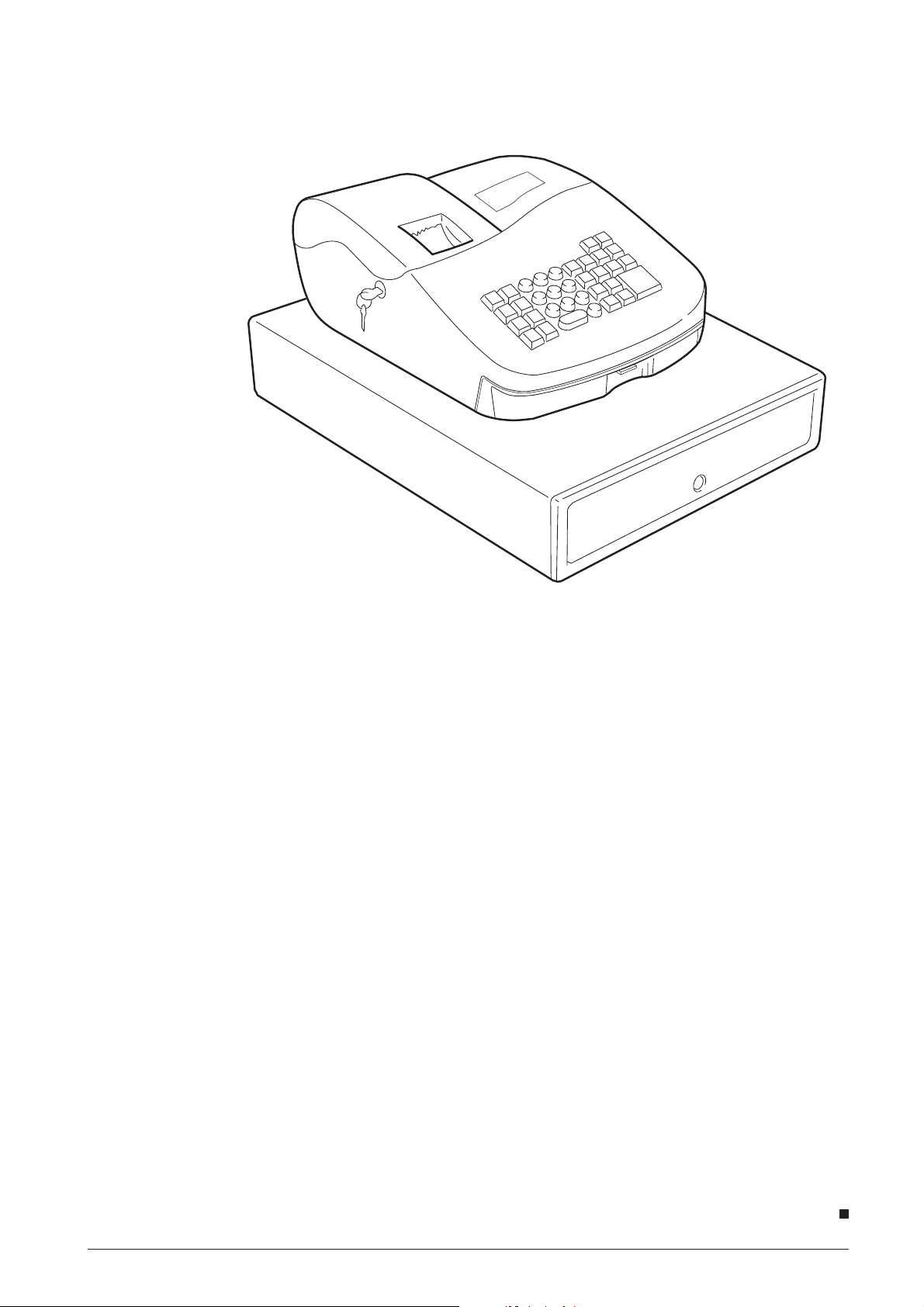
Fig. 1-1
Electronic cash register with printer and eight
departments
Fluorescent display , symbols f or error , change,
minus, total and program mode
Input 7 digits and readout
Serial printer with ink roller
57-mm single ply register tape
Approx. 3 months after power interruption via
4 AA batteries
CMOS RAM
220-240V 50/60 Hz ~ 115V 50/60 Hz
0.07A; operating 0.22A
Operating temperature:
Dimensions:
Weight:
686710D Service Manual 1-1
686711S
0° to 40°C
Depth 425 mm, width 324 mm, height 220 mm
Approx. 6 kg
.
Page 8

Page 9

2. SPECIFICATIONS AND
OPERATING PRINCIPLES
2.1 SPECIFICA TIONS
2.1.1 Features
The Micro Printer was designed and developed as a
printer for use with calculators. It offers the following
features:
• Ultra-compact and lightweight design.
• Use of movable type for sharp printing quality.
• High printing speed due to a carriage return
mechanism that can return the carriage from any
column position.
• Silent operation and printing.
• Provided with quick feeding and paper free
functions.
• Use of ordinary calculator paper.
• Requires no control of the motor speed.
2.1.2 Specifications
The main specifications are listed as follows.
Print method
Type-printing serial printing
Carriage width
Max. 19 printable columns (including one column of
symbols)
Character position
On symbol column side: 13 positions +1 empty
positions
On numeric column side: 14 positions
Character size
1.6 (W) x 2.5 (H) mm
Intercharacter intervals
Between numerics: 2.1 mm
Between a numeric and symbol: 2.6 mm
Line spacing: 4.6 mm
Paper (Supplied by the user)
Type: Regular paper
Size: Width 57.5 mm +/- 0.5 mm
Roll diam.: 80 mm or less
Thickness: 0.06 - 0.085 mm
Aver age weight: 47 g/m2 - 64 g/m
(40 - 55 kg/1000 sheets/1091 x
788 mm)
Paper feed
TYP 8 lps. Fast paper feeding is also possible and a
paper release mechanism is provided.
Inking
Ink roll method
Colors : Purple or black
Ink roll life: Purple 1,000,000 characters
Black 350,000 characters
Standard: IR-40
Motor
Terminal voltage: 6.0 +0.5 -2.0 VDC
Average current: Approx. 0.25 A (during 19
columns 7 character shift
printing at 6.0 VDC, 25°C)
Detector
Mechanical point of contact
Reset signal "R", Timing signal "T", and a Sub-Timing
signal "t"
D .C. resistance: Approx. 20 Ohm +/- 2 ohm (at 25°C)
Connection method
Jumper Wire on printer side
Guaranteed operating temperature
0°C - 50°
External dimensions
86 (W) x 58.4 (D) x 19 (H) mm
Weight
Approx. 90 g.
2
Print speed
Average printing speed at 6.0 VDC
19-column printing: TYP 0.9 l/s
7-column printing: TYP 2.2 l/s
686710D Service Manual 2-1
Page 10
2.1.3 Mechanisms
This printer consists of two print wheels, a hammer,
and a carriage equipped with an ink roll. It is a serial
printer with movable type, and performs printing by
sequentially moving across from the lowest-order
column.
When the motor is activated, the gear trains rotate
and cause the print wheels and detection wheel to
rotate. When the trigger coil is charged according to a
signal (which corresponds to a character) output from
the detector, character selection is perf ormed, the print
wheel stops, the print gear is rotated by the action of
the planet gear, a character is printed then the carriage
shifts to the next column (column-shift operation).
When the charge to the trigger coil is lengthened
during character selection performed at the end of
line, printing is performed then the carriage is returned
to the initial column and the paper is fed forward,
thereby completing the printing of one line.
This printer consists of five mechanisms: the
transmission and selective mechanism, detection
mechanism, print mechanism, inking mechanism, and
paper feeding mechanism.
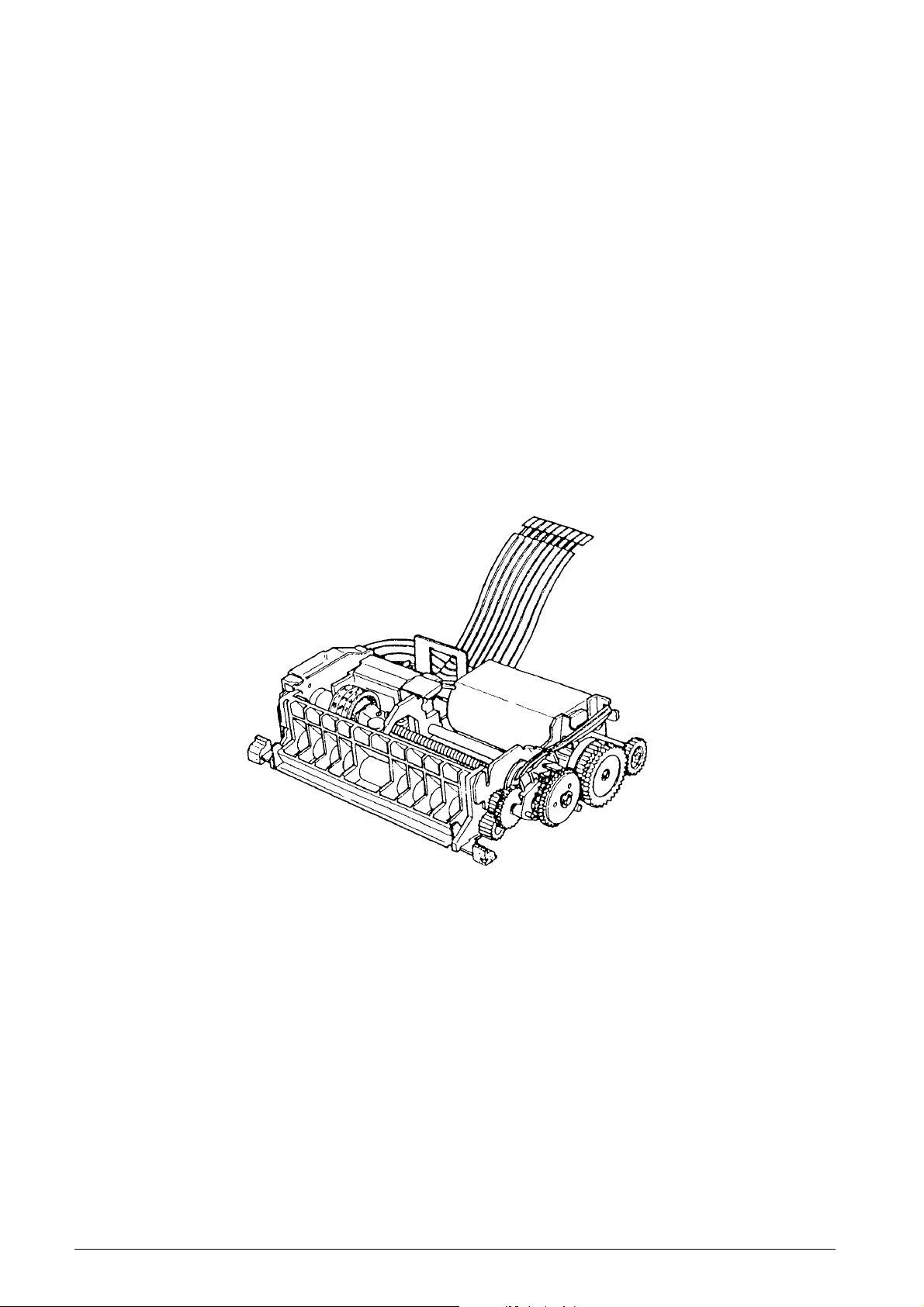
Fig. 2-1 shows an external view of the Micro Serial
Printer. For details on the operating principles and
handling of each mechanism, see section 2.2,
“OPERATING PRINCIPLES”, and Chapter 3,
“HANDLING, MAINTENANCE, AND REPAIR”.
Fig. 2-1 Exterior View
2-2 Service Manual 686710D
Page 11
2.2 OPERATING PRINCIPLES
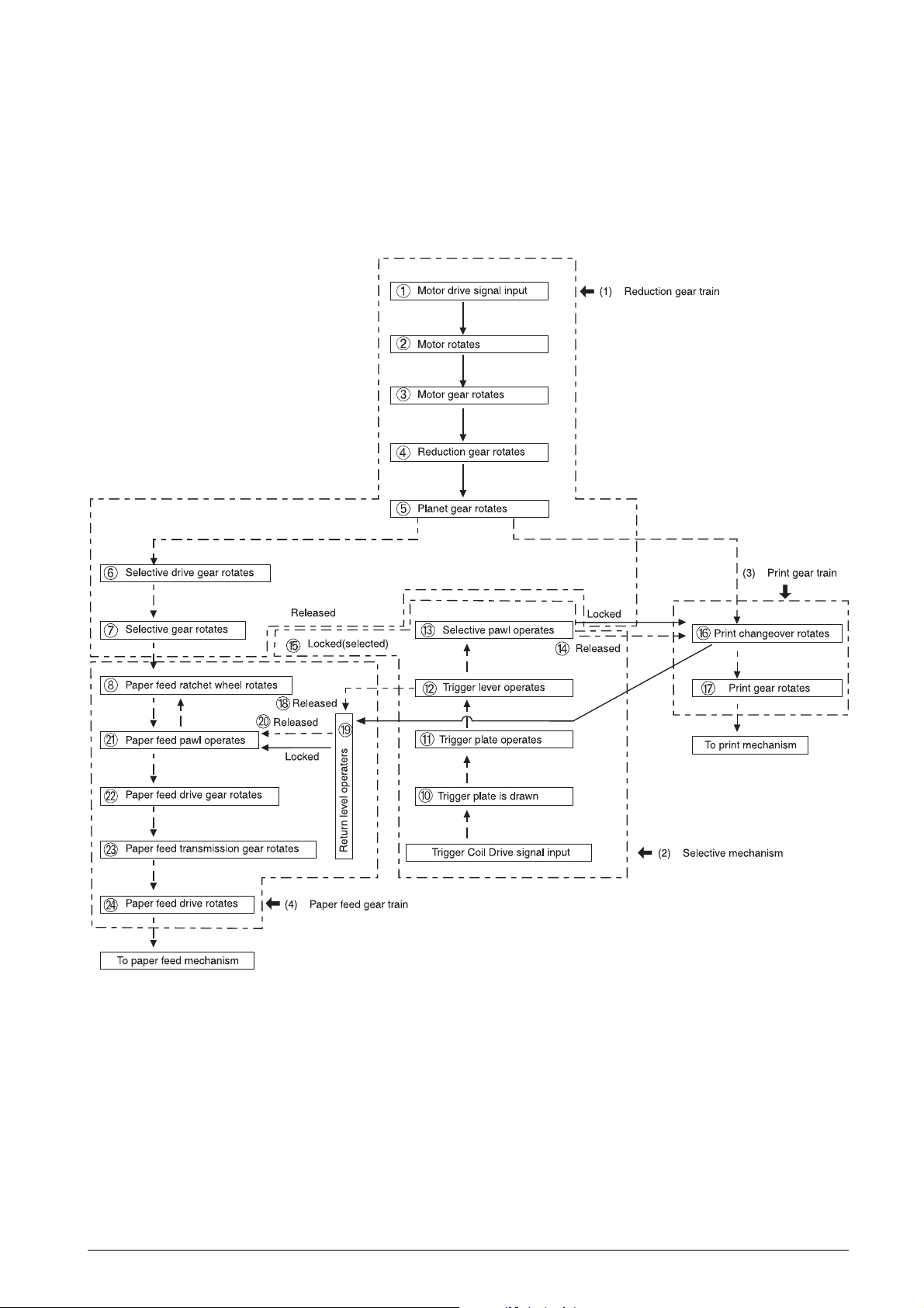
2.2.1 Transmission/Select Mechanism
As shown in Fig. 2-2, this mechanism consists of the
reduction gear train, selective mechanism, print gear
train, and paper feed gear train.
➈
Fig. 2-2 Transmission/Select Mechanism
686710D Service Manual 2-3
Page 12
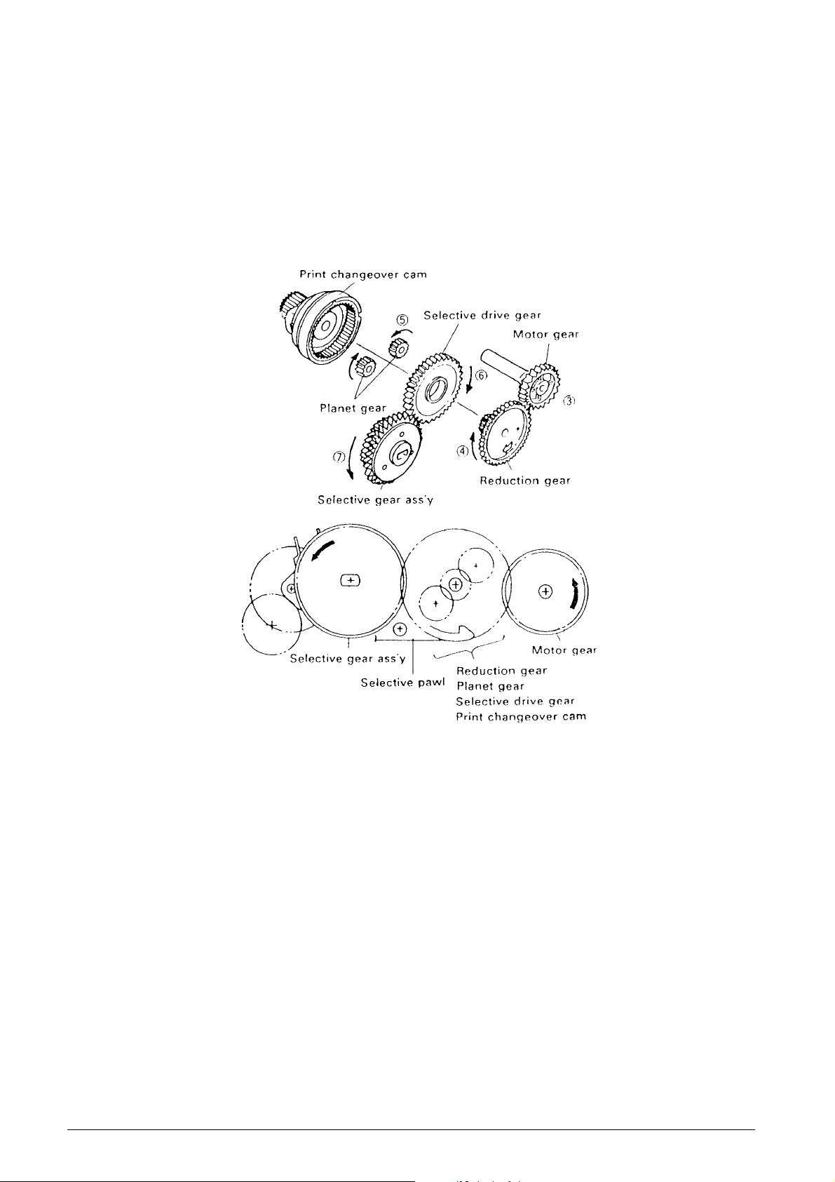
Reduction gear series (See Figs. 2-2 and 2-3.)
The reduction gear train consists of the motor gear,
reduction gear, planet gear, selective drive gear,
selective gear assembly, selective pawl, and print
changeover cam. When the motor rotates 2, the
rotation force is sequentially reduced from the motor
gear 3 on the same shaft through the gear tr ain to the
selective gear assembly 7.
The rotation of the print changeover cam is lock ed by
the action of the selective pawl, so the paper feed
ratchet wheel 8 on the same shaft as the selective
gear assembly, the print wheel, and detection wheel
also rotate at the same time.
Fig. 2-3 Reduction Gear Series
2-4 Service Manual 686710D
Page 13
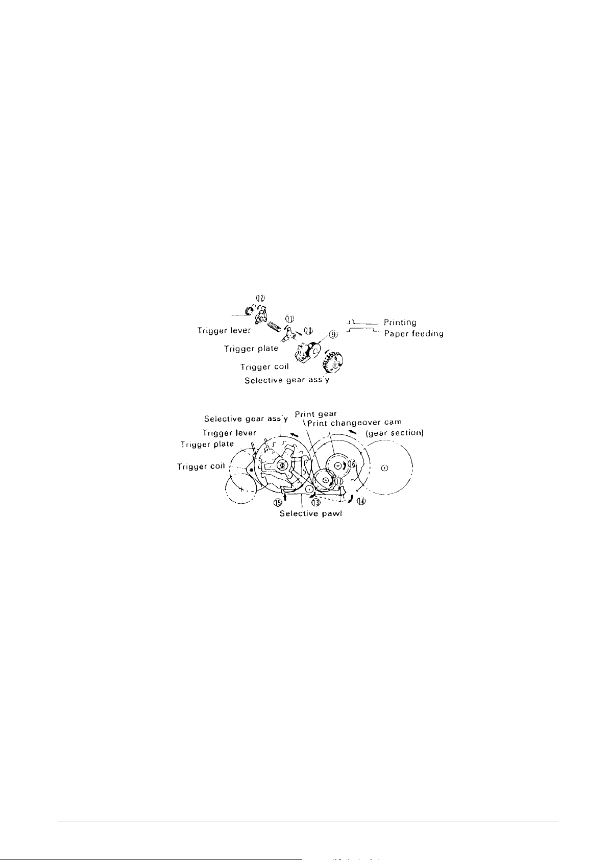
Select mechanism (See Figs. 2-2 and 2-4.)
As shown in Fig. 1-4, the select mechanism consists
of the selective gear assembly, trigger coil, trigger
plate, and selective pawl. During rotation of the
reduction gear series, when a Drive signal is input 9
to the trigger coil in conformance with the Timing signal
output from the detector, the trigger plate is drawn 10
to the yoke fixed onto the selective gear assembly so
that the trigger plate 11, trigger lever 12, and selectiv e
pawl 13 rotate together with the rotation of the selective
gear assembly. At the same time as the print
changeover cam is unlocked, the selectiv e pawl loc ks
15 the tooth section corresponding to the character
of the selective gear assembly. When the selective
gear assembly is stopped, the print wheel mounted
on the same shaft is stopped also, and character
selection is performed.
Print gear series (See Figs. 2-2 and 2-4.)
The print gear series consists of the print changeover
cam and print gear. When the selectiv e gear assembly
is stopped by the select mechanism, the interlocked
selective drive gear is also stopped. At the same time,
the unlocked 14 print changeover cam is coupled and
is rotated 16 by the planet gear of the rotating reduction
gear series. The print gear thus rotates 17 which is
transmitted to the printing mechanism.
Fig. 2-4 Select Mechanism and Print Gear Series
686710D Service Manual 2-5
Page 14
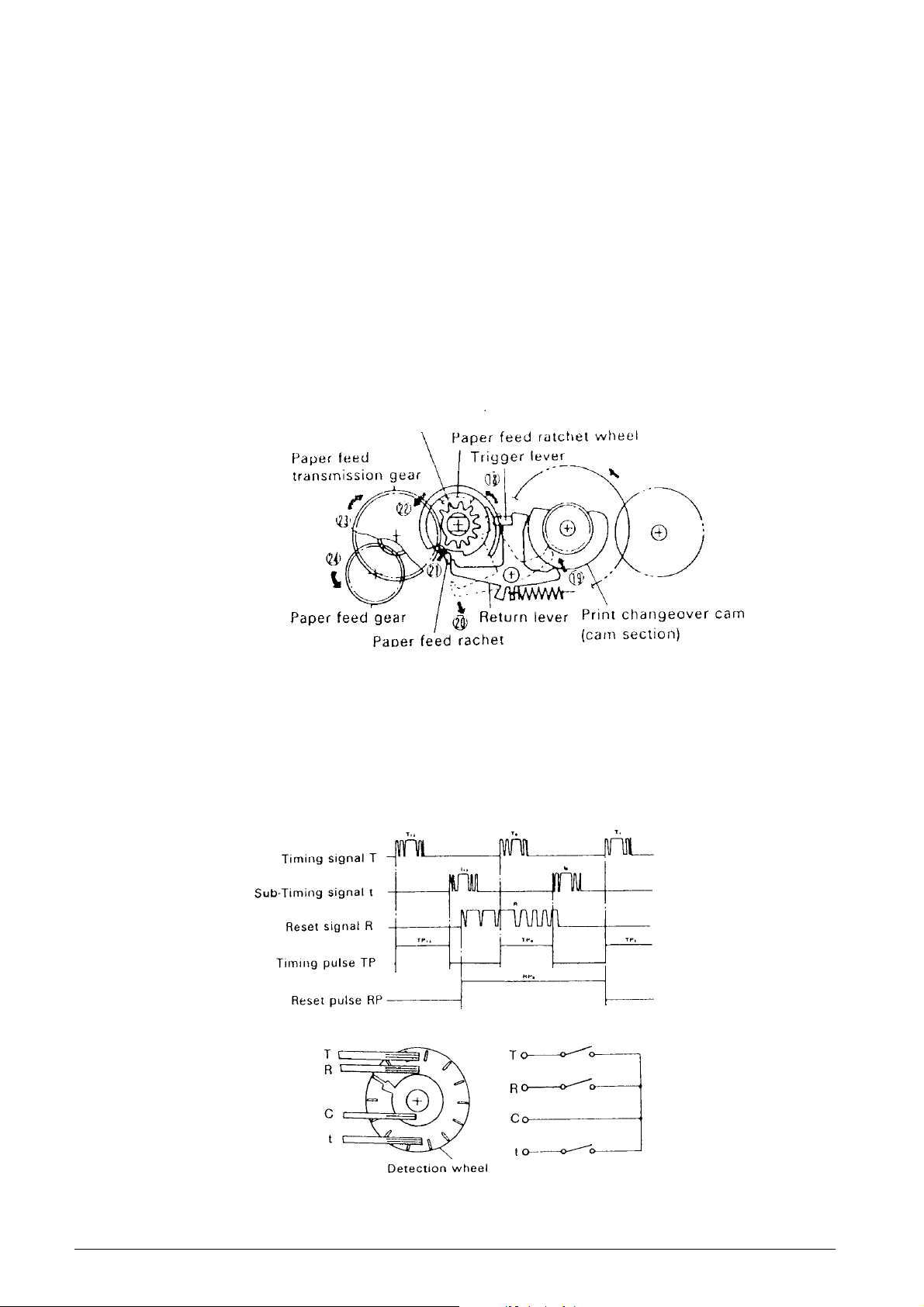
Paper feeding gear series (See Figs. 2-2 and 2-5.)
As shown in Fig. 2-5, the paper feeding gear series
consists of the paper feed ratchet wheel, paper feed
drive gear assembly, paper feed transmission gear,
and paper feed gear.
During column selection or consecutive paper feeding,
although the select mechanism and printing gear
series will operate through lengthening the Trigger Coil
Drive signal at the first column during space selection,
the return lever and trigger lever are in the unlocked
status 18 in order to maintain a long operating status
of trigger plate and trigger lever.
When the print changeover cam rotates, because the
cam controlling the return lever reaches a notched
section, the return lever is released and begins
operating 19 due to spring force, and its interlocking
with the paper feed ratchet in the paper feed drive
gear assembly is cancelled 20.
Selective gear assembly
The paper feed ratchet operates 21 due to spring force,
and meshes with the teeth of the paper feed ratchet
wheel which is on the same shaft as the selective gear .
When the printing operation is completed, the print
changeover cam causes the selective pawl to return
to its pre-selection status, and the print changeover
cam is stopped. When the selection gear begins
rotation, the paper feed driver gear assembly 22, paper
feed transmission gear 23 and paper feed gear 24 all
rotate together with the paper feed ratchet wheel, which
is transmitted to the paper feeding mechanism.
Fig. 2-5 Paper Feeding Gear Series
2.2.2 Detector Mechanism
(See Fig. 2-6.)
The detector mechanism consists of the detector
assembly and the detector gear. The detector employs
a mechanical contact-point system and generates a
Timing signal "T" and Sub-Timing signal "t" in
correspondence to each character position on the print
wheel.
The detector also generates a signal Reset signal at
each rotation of the print wheel. W av eform rectification
of these signals is to be performed by the user to use
as Timing pulses or Reset pulses.
Fig. 2-6 Detector Mechanism
2-6 Service Manual 686710D
Page 15
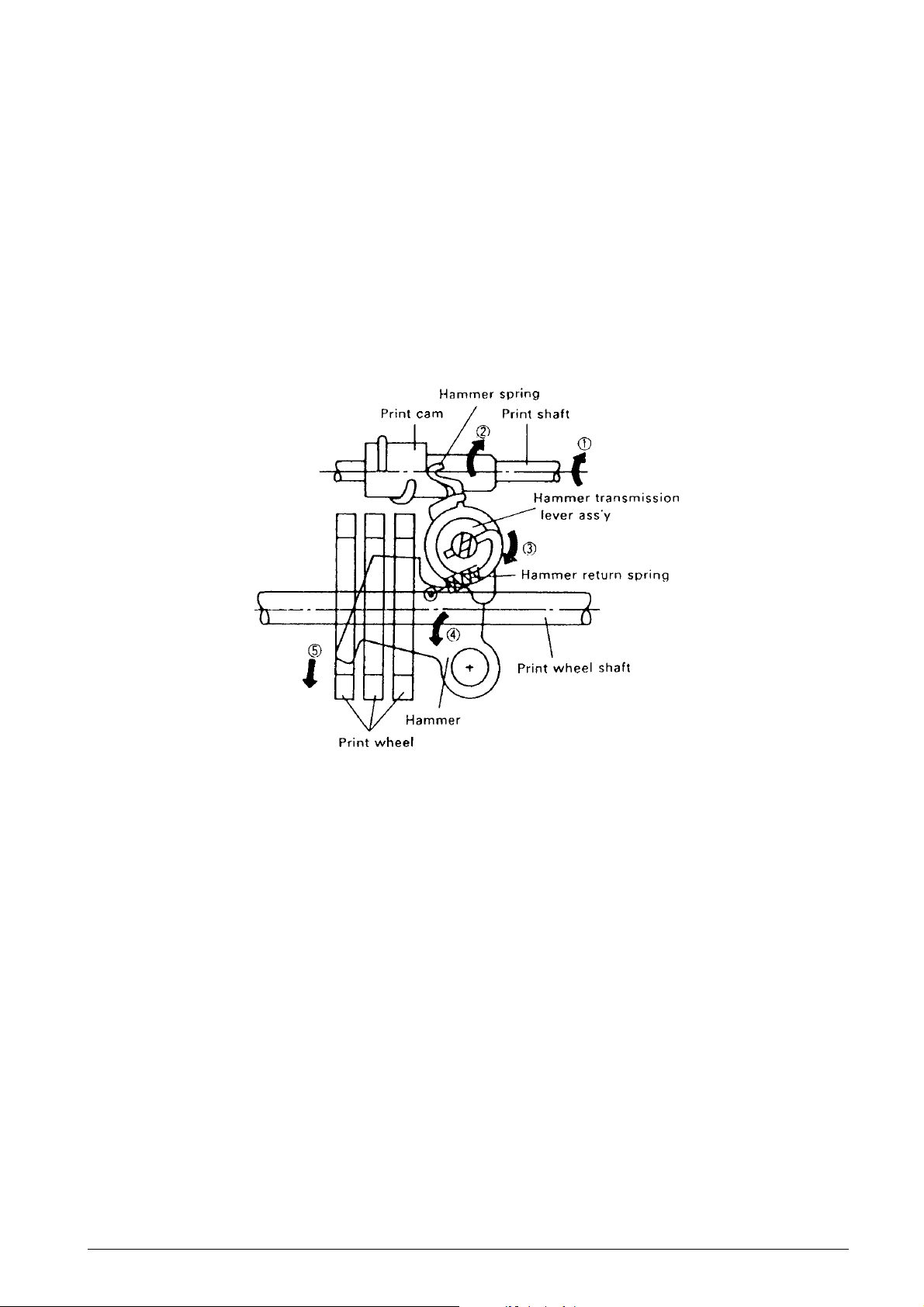
2.2.3 Printing Mechanism
The printing mechanism performs two functions: the
printing operation and carrying operation.
Printing operation (See Fig. 2-7.)
When the print gear series (see subsection 2.2.1,
Transmission/Select Mechanism) causes the print
shaft and print cam to rotate in the ➡ arrow 1 and 2
directions, the hammer transmission lever assembly
and hammer rotates in the ➡ arrow 3 and 4 directions;
therefore, the print wheel is pressed in the ➡ arrow 5
direction by the hammer, and printing is performed.
The hammer return spring moderates the pressure of
printing and also functions to restore the hammer and
hammer transmission lever assembly to standby
status at the completion of printing. The print wheel,
similar to the print changeover cam, makes one
rotation with each printing operation, and the printing
operation is performed during the first half of the
rotation.
Fig. 2-7 Printing Operation
686710D Service Manual 2-7
Page 16
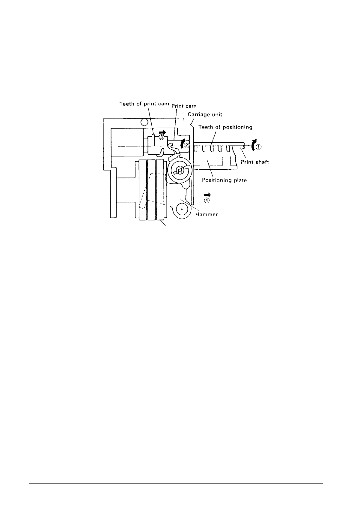
Carrying operation (See Fig. 2-8.)
The carrying operation is performed after the printing
operation during the last half of the print shaft rotation.
As soon as the positioning plate causes the print gear
to begin rotating, the cam section of the print gear
causes its meshing with the return lever to be
unlocked, and the print gear meshes with the print
cam.
When the print shaft rotates in the ➡ arrow 1 direction,
the meshing between the teeth of the print cam and
positioning plate causes the print shaft to slide to the
➡ arrow 2 direction while rotating in the ➡ direction
while in the ➡ arrow 3 direction. Sim ultaneously with
this sliding action, the carrying operation of the
carriage unit is performed (➡ arrow 4).
Print wheel assembly
Fig. 2-8 Carrying Operation
2-8 Service Manual 686710D
Page 17
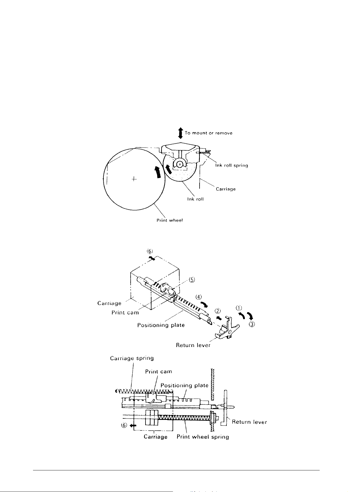
2.2.4 Inking Mechanism
(See Fig. 2-9.)
The ink roll assembly is constantly pressed lightly
against the outer periphery of the pr int wheel due to
the operation of the ink roll spring.
When the print wheel rotates, the ink roll also rotates
and the ink is supplied.
2.2.5 Paper Feeding Mechanism
The paper feeding mechanism performs two functions:
the carriage return operation and the paper feeding
operation.
Carriage return operation (See Fig. 2-10.)
The paper feeding gear series (see subsection 2.2.1,
“Transmission/Select Mechanism”) causes the return
lever to drop into the cam section of the print changeover cam so that it meshes with the positioning plate
(➡ arrows 1 and 2). The rotation of the print
changeover cam restores the return lev er to its original
position (➡ arrow 3) and rotates the positioning plate
with which it is meshed (➡ arrow 4). As a result, the
teeth of the positioning plate and print cam become
disengaged (5), and the spring force of the print wheel
spring and carriage spring causes the carriage to be
returned (➡ arrow 6).
Fig. 2-9 Inking Mechanism
Fig. 2-10 Carriage Return Operation
686710D Service Manual 2-9
Page 18
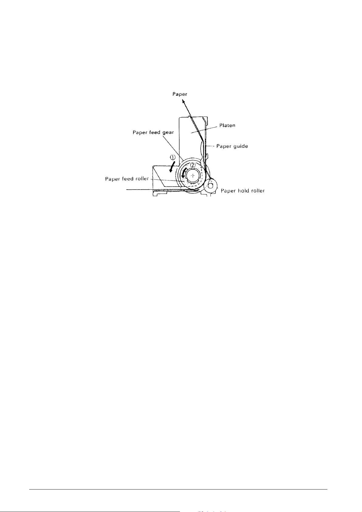
Paper feeding operation (See Fig. 2-11.)
Paper feeding is executed while the paper feed drive
gear assembly performs one rotation. When the paper
feeding gear series (see subsection 2.2.1,
"Transmission/Select Mechanism") causes the paper
feed gear to rotate in the ➡ arrow 1 direction, the paper
feed rubber within the platen also rotates in the ➡
arrow 2 direction, and the paper is f ed by friction from
Fig. 2-11 Paper Feeding Operation
the paper hold roller, which is in contact with the paper
feed rubber.
When the paper feed ratchet within the paper feed
drive gear assembly strikes the return lever, it
becomes disengaged with the paper feed ratchet
wheel, the rotation of the paper feed drive gear
assembly is stopped, and paper feeding is terminated.
2.2.6 Printer Operation During One Print
Cycle Initialization
To confir m that the carriage is in standby status (at
the first column), initialization must be performed prior
to printing and paper feeding. Initialization is completed
performing line feed.
Printing of the first line
1
The Timing pulses
Motor Drive signal is applied and the motor is
activated. The Reset pulse "RP" appearing 8 Timing
pulses shall be regarded as "RPo" and the first
Timing pulse "TP" after the rising of "RPo" shall be
regarded as "TPo".
2
Character selection (First column)
The Trigger Coil drive pulse is applied to the trigger
coil during the interval from Timing pulse "TPn" to
"TPn+1” which correspond to the desired character.
At such time, the Timing pulse interval ("TPn" to
"TPn+1”) is measured to obtain "TW1”. Following
character selection, the print wheel stops (the
timing pulse retains the "TPn+1” status), then print
and carrying are automatically executed.
3
Character selection (second column)
The print wheel starts rotating again and the first
Timing pulse is TP12. Character selection can be
performed from the next Timing pulse TP13. The
rest of this character selection operation is identical
to that described in Step (2) above.
"TP" are counted after the
4
Carriage return and paper feeding
During character selection for the highest-order
column of a line of print, printing, carriage return,
and paper feed are performed by adding: [the
width of the drive pulse to the trigger coil] + [the
timing pulse interval TW2 (TPn to TPn+1) at the
time] + [(the TP interval TW1 measured during
selection of the 1st column) x 6].
5
Motor OFF
After completing the printing of the highest-order
printing is one line of printing, the print wheel
begins rotation and the Timing pulse "TP" is
generated. Counting from this initial rising pulse,
the Motor Drive signal is cut off at the rising of the
fourteenth Timing pulse "TP".
NOTES:
• During a one-line print cycle, confirm the Reset
pulse "RP" between Timing pulses "TP13" and
"TPo" or "TPo" and "TP1”.
• The first Timing pulse that is generated after the
print column-shift process (TPn"2) cannot be used
for character selection.
2-10 Service Manual 686710D
Page 19

Consecutive printing
Fast paper feeding
1 The process for the initial line is similar to that for
"Printing of the first line".
2 Printing of the second and later lines begins as
follows: After completing the printing of the highestorder column for printing of the first line, with the
motor remaining driven, count the following Timing
pulses "TP". From the rising of the 29th Timing
pulse, pinting of the first column of the second line
becomes possible. Next, follow Steps 2 to 4 of
"Printing of the first line".
3 Consecutive printing is performed by repeating
Step 2 above.
4 Motor OFF
Perform Step 5 of "Printing of the first line".
Paper feeding of the first line
1 The Timing pulses "TP" are counted after the
Motor Drive signal is applied and the motor is
activated. The Reset pulse "RP" appearing 8
Timing pulses shall be regarded as "RPo" and the
first Timing pulse "TP" after the rising of "RPo"
shall be regarded as "TPo".
1 The process for feeding the initial line is similar to
that for "Paper feeding of the first line".
2 Paper feeding of the second and later lines begins
as follows: After completing the paper feeding of
the first line, with the motor remaining driven,
count the following Timing pulses "TP". From the
rising of the 21st Timing pulse, selection of the
empty character "TP10" becomes possible. Next,
follow Step 2 of "Paper feeding of the first line".
3 Fast paper feeding is performed by repeating Step
2 above.
4 Motor OFF
Perform step 3 of "Paper feeding of the first line".
2 Paper feeding
Select the empty character "TP10". At such time,
measure the Timing pulse interval "TP10" to "TP11”
to obtain TW1. When the width of the Trigger Coil
Drive pulse equals the measured "TW1” plus six
times "TW1”, the empty character on the print
wheel is selected and paper feeding is performed.
3 Motor OFF
After completing the paper feeding of one line, the
print wheel begins rotation. Counting from the
initial rising Timing pulse, the Motor Drive signal is
cut off at the rising of the fourteenth Timing pulse
"TP".
NOTE:
• During a one-line print cycle, confirm the Reset
pulse "RP" between Timing pulse "TP13" and
"TPo" or "TPo" and "TP1”.
686710D Service Manual 2-11
.
Page 20

Page 21
3. HANDLING, MAINTENANCE, AND
REP AIR
3.1 HANDLING THE PRINTER
3.1.2 Paper Setting
Loading the Paper
When loading the paper into the printer, note the
following points.
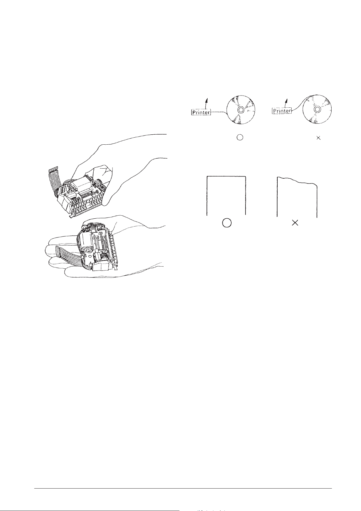
3.1.1 Precautions on Printer Handling
Precautions on transport (See Fig. 3-1.)
(1)When transporting this printer, never carry it by
grasping only the jumper lead.
(2)Never expose the printer to impact by dropping or
striking it, placing two printers into contact or
similar means.
Paper Setting Procedures (See Fig. 3-2.)
Fig. 3-2 Paper Setting Procedures
The Leading Edge of Rolled Paper (See Fig. 3-3.)
Fig. 3-3 The Leading Edge or Rolled Paper
Fig. 3-1 Proper Handling of Printer
Precautions on storage
• Avoid storage in locations exposed to excessive
dirt or dust, direct sunlight or excessive moisture.
• In the case of long-term storage (over 1 month),
place the printer a polyethylene bag after wrapping
it in anti-rust (VPI) paper, then store it in a dry
location.
Precautions on use
• Since this printer employs a permanent magnet
(motor section), avoid using it in locations exposed
to excessive iron filings, dirt, dust or other foreign
particles.
• Never perform a printing operation without the
paper and ink roller installed.
• Make sur you use only the paper and ink roll
assembly that are stipulated in the specifications.
• The ink roll assembly is a disposable part; do not
attempt to refil its ink supply.
Precautions on paper insertion
• Insert the paper straight into the paper entrance
section. Never insert paper having an uneven
leading edge at a slant.
• If the paper is pushed in the direction of feeding,
paper insertion will be simplified.
Removing the Paper
Remove the paper by following on the two methods
below.
• Perform paper feed using an electrical operation
(switch the printer power to ON, then press the
Paper Feed button), then remove the paper.
• Although the paper release mechanism in standby
status allows the paper to be freely removed by
pulling it out towards the front or back, make sure
to pull it straight out of the printer. Pulling the
leading edge out at a slant causes paper
jamming.
686710D Service Manual 3-1
Page 22
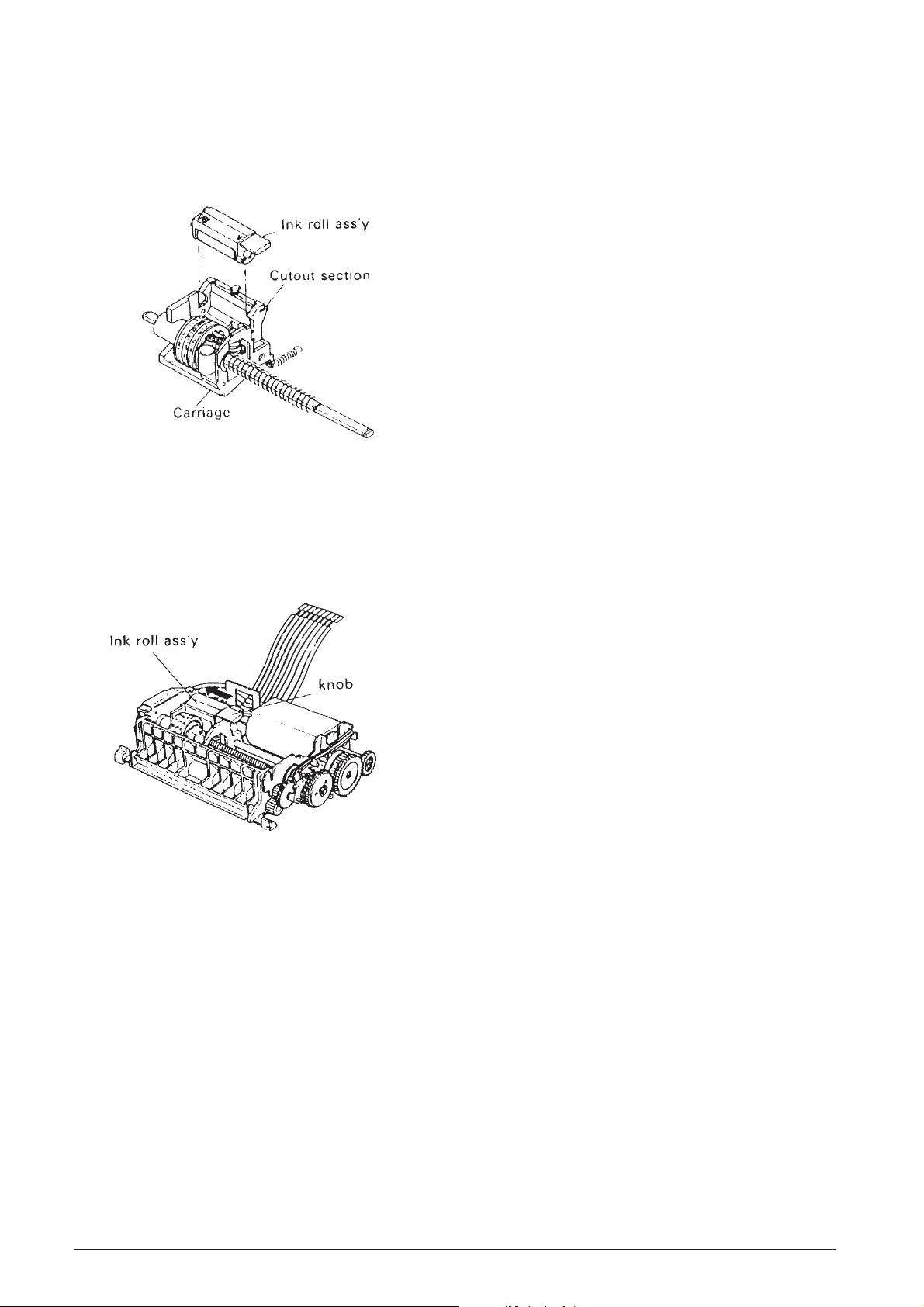
3.1.3 Installating the Ink Roll Assembly
3.2 MAINTENANCE
Fiting the Ink Roll Assembly (See Fig. 3-4.)
• Set the ink roll assembly in the cutout sections of
the carriage, then press it down gently until it clicks
into place.
Fig. 3-4 Installation of Ink Roll Assembly
Replacement of ink roller assembly
(See Fig. 3-5.)
• Press the knob of the ink roll assembly in the ➡
arrow direction, then lift the ink roll assembly up
and out of the carriage.
To ensure this printer retains its initial performance
level throughout a long product life, and to prevent
potential troubles, be sure to perform maintenance
and management according to the points described
in the following subsections.
3.2.1 Cleaning
Eliminating dirt or stains
Wipe off the soiled sections using alcohol or benzene.
Eliminating dust, scraps, and other foreign
particles
Use a vacuum cleaner to carefully draw out all f oreign
particles from every par t of the printer.
NOTES:
Never use thinner , tricholyene nor k etone solvents as
they may deteriorate or damage the plastic parts.
Check the remaining lubricant of each cleaned section
and perform lubrication as required. (See subsection
3.3.3, “Lubrication Points”.)
3.2.2 Inspection
Fig. 3-5 Replacement of Ink Roller Assembly
The maintenance and check-up procedures for this
printer are grouped into two types:
1) Daily checks that can be easily performed by the
operator of the printer during the course of daily
work, and
2) Periodic checks that can be performed only by
persons having a thorough understanding of the
printer mechanisms. These maintenance and
check procedures should be implemented
according to the technical level of the person
conducting them.
3-2 Service Manual 686710D
Page 23

Periodic Check
Every six months, periodic maintenance and inspection
of the points below should be conducted:
Check Item
Adhesion/penetration
of dirt, paper scraps,
or dust to the printer
interior.
Shape of the springs.
Lubrication status.
Printing and paper
feeding.
Standard
• No excessive adhesion
of dirt, paper scraps or
dust.
• No deformed springs.
• See subsection 3.3.1,
“Lubrication
Requirements”.
• No defects in the printed
results.
• No defects in the paper
feeding.
• Observe each function
and confirm the
absence of worn or
deformed parts, paper
jams, and other defects.
Repair Method
• Use a vacuum
cleaner to carefully
remove all foreign
matter from the
printer.
• Replace any
deformed springs.
• See subsection
3.3.3, “Lubrication
Points”.
• See subsection
3.5.3, “Repair
Guidelines”.
Daily check
The printer and printer operation are checked to see
if the printer is being operated in the proper manner
and if it is being maintained in optimum condition.
If any unsatisfactory points are discovered, they should
be remedied.
• Check that the ink roller ass’y is securely installed
in the carriage.
• Check the ink roller in use conforms to the
specifications (IR-40). Check the ink roller for
damage, replacing the ink roller if the ink roller
status is affecting printing quality.
686710D Service Manual 3-3
Page 24

3.3 APPLICATION OF LUBRICANTS
3.3.2 Lubricating Requirements
Lubrication plays an important role in maintaining this
printer at its initial performance level throughout a long
product life as well as preventing potential troubles.
Make sure to apply the specified lubrificants in the
appropriate amounts at the specified intervals.
3.3.1 Lubricant Types
The type of oil used greatly influenoes performance
and durability, and special attention is required to its
low temperature characteristics. Consequently , the oils
to be used with this printer are specified by us on the
basis of the results of the thorough analyses of data
for many types of oils and various experiments.
Note that our specified oils are availab le in 40cc (gm)
containers (minimum supply unit).
The three types of oils to be use with this printer are:
G-20, G-34 and 0-3.
No.
Lubrication Point
Prior to lubricating a part during assembly or
disassembly, that par t must be thoroughly cleaned.
The points requiring lubrification and the
corresponding lubricant types are listed in subsection
3.3.3, “Lubrication Points”, and shown in Fig.4-2,
“Lubrication Points” (Note that corresponding numbers
are used in the table and figure).
Lubrication should be periodically performed after
every six months, every overhaul, or every 700,000
printed lines. If lubrication becomes deficient due to
cleaning, disassembly or parts replacement, be sure
to perform lubrication regardless of the actual
lubrication interval.
3.3.3 Lubrication Points
(See also Fig. 4-2)
* (1), (2), (3), (11), (12) and (13) require lubrication
during assembly.
Oil Type
(1)
(2)
(3)
(4)
(5)
(6)
(7)
(8)
(9)
(10)
(11)
(12)
(13)
Flanged section of paper feeding ratchet wheel
(contact point between frame and teeth).
Contact point of detection wheel with frame.
Contact point between selective gear ass’y and trigger
plate.
Contact point between print shaft and frame (2 points).
Outer surface of print shaft.
Outer surface of print wheel shaft.
Contact point between print cam and hammer spring.
Teeth of positioning plate (3 points from the T side).
Contact point of positioning shaft with frame and
return lever (3 points).
Print gear cam.
Planet gear (teeth and shaft entrance section) (2
points).
Contact point of the selective drive gear with the
reduction gear.
Entire outer surface of detection wheel.
G-34
G-34
0-3
0-3
0-3
0-3
G-34
0-3
0-3
0-3
0-3
0-3
G-20
(14)
(15)
(16)
Contact point of selective pawl with print changeover
cam.
Contact point between print wheel ass’y and carriage.
Contact point between guide shaft with frame and
carriage.
0-3
0-3
0-3
3-4 Service Manual 686710D
Page 25

3.4 TOOLS AND LUBRICANTS
3.5.2 Repair Procedures
3.4.1 List of Tools
Tool Designation
Electric soldering iron
Round-nosed pliers
Diagonal-blade nippers
T weezers
Brush-Medium # 1
Brush-Thin # 2
Phillips screwdriver No. 1
ET holder # 1.5
O
Commercially available
Availability
O
O
O
O
O
O
O
O
3.4.2 List of Lubricants
Item
Oil
Grease
Designation
0-3
G-20
G-34
Volume
40 gm
40 gm
40 gm
3.5 REPAIR
In consideration of the level of expertise required for
implementation of after-service and repair procedures
for this printer, such procedures have been grouped
into two rankings: Le vel A and Level B . The person in
charge of repair, theref ore , should perform the repair
procedures appropriate to the repair level and to his/
her own level of expertise.
If of problem occurs, check its symptoms and status
and clarify the source of the problem with reference
to subsection 3.5.3, “Repair Guidelines” then repair
the damaged area. Note that the tab les of subsection
3.5.K3, “Repair Guidelines”, consist of the five items
listed below, enabling troubleshooting and repair to
be performed with speed and efficiency with minimum
error.
Phenomenon
Check the symptoms of the trouble.
Condition
Compare the trouble status of the problem with the
description in this column and locate the matching
status.
Cause
This columns lists the potential causes on the basis
of the trouble status, allowing the location of the trouble
to be checked.
Check-Point & Method
In correspondence to the cause, this column lists what
parts to check as well as the checking procedure to
be used. Be sure to inspect the chec k-points according
to the method describe here.
Repair Method
Repair the trouble area according to the description
in this column. If the identical phenomenon and
condition remain unchanged after performing the
rapair, chec k another item of the “Cause” column, then
perform the relative repair.
NOTE:
If you wish to carefully check the operation of such
parts as the gears, manually rotate the motor gear in
the counter-clockwise direction to perform such check.
3.5.1 Repair Levels
LEVEL A:
Requires general knowledge and technical skills
regarding the operating principles and structure of the
printer, but does not require previous repair
experience.
LEVEL B:
Requires full knowledge and technical skills regarding
the structure and operating principles of the pr inter
as well as previous repair experience.
686710D Service Manual 3-5
Page 26

3.5.3 Repair Guidelines
PHENOMENON CONDITION CAUSE LEVEL
1. Motor doesn't
rotate.
Motor doesn't
rotate despite
issuing of print
istruction or its
rotation becomes
locked.
(1) Defect of
power input
to motor.
(2) Defective
conductivity
of jumper
wire.
(3) Locking of
hammer and
print wheel
ass'y.
(4) Adhesion
of foreign
matter to the
rotating
mechanism
- - Check the input
A - Check the
B - Manually rotate the
(B) - Manually rotate the
CHECK POINT AND
METHOD
power. Use a tester or
oscilloscope to check
the input voltage
between the motor
terminals.
conductivity between
the motor terminals.
motor gear and check
whether the operation
of the print wheel ass'y
and other mechanisms
is normal.
motor gear in the
counter-clock-wise
direction and check for
the adhesion of foreign
matter. Remove any
foreign matter.
REPAIR METHOD
- Inspect and repair
the power supply
circuit.
- Perform resoldering
or replace the jumper
wire.
- Replace the hammer.
- Remove any foreign
matter.
2. No column
printing is
performed.
Motor rotates
normally, but no
printing is
performed.
(5) Improper
mounting
position of
the print
changeover
cam.
(6) Defective
motor.
(1) Defective
conductivity
of jumper
wire.
(2) Broken
coil lead of
trigger coil.
- See Main Assembly
B in the chapter 4 and
check.
B - Check the above
Cause (1) to (5) to see
if they are applicable.
A - Check the
conductivity between
across the terminals of
detector ass'y and
trigger coil.
B - Measure the
resistance value of the
trigger coil.
Rating: 20 +/- 2 Ohm
(at 25°C).
- Properly re-position
the print changeover
cam.
- Replace the motor.
- Perform resoldering
or replace the jumper
wire.
- Replace the triggle
coil.
3-6 Service Manual 686710D
Page 27

PHENOMENON CONDITION CAUSE LEVEL
CHECK POINT AND
METHOD
REPAIR METHOD
2. No column
printing is
performed.
Motor rotates
normally, but no
printing is
performed
(3) Improper
position of
print
changeover
cam.
(4) Broken
hammer
spring
(hammer
transmission
lever ass'y).
(5) Faulty
engagement
between the
print cam and
hammer
spring
(hammer
transmission
lever ass'y).
(6) Abnormal
charge pulses
to the trigger
coil.
B - See CAUSE (5) of
PHENOMENON !
B - Remove the ink roll
ass'y and check if the
spring is broken.
B - See Main Assembly
A in chapter 4 and
check.
B - Check if the charge
pulsewidth are within
rated values.
- Replace the hammer
transmission lever
ass'y.
- Properly engage the
print cam and hammer
spring.
- If they easily become
disengaged, bend the
hammer spring to
ensure engagement.
- Perform repair on the
circuit side.
3. Incomplete
printing.
Top, bottom or
sides of printed
characters are
missing.
(1) Faulty
mounting of
the platen
ass'y.
(2) Wear to
the print cam,
hammer
transmission
lever ass'y or
hammer.
(3) Wear or
adhesion of
foreign
particles to
positioning
plate.
(4) Foreign
particles
adhered to
print wheel
ass'y or
hammer.
A - Check if the platen
ass'y is firmly mounted
in the frame.
B - Manually set the
trigger lever into drawn
status, then perform a
printing operation to
check the hammer
stroke.
B - Check the
column-shift teeth of
the positioning plate
for wear and for the
adhesion of foreign
matter.
A - Check if foreign
matter is adhered to
front or back of the
hammer tip and print
wheel.
- Properly re-mount it.
- Replace any worn
parts.
- Replace the
positioning plate.
- Remove any foreign
matter.
- Remove particles.
686710D Service Manual 3-7
Page 28

PHENOMENON CONDITION CAUSE LEVEL
CHECK POINT AND
METHOD
REPAIR METHOD
3. Incomplete
printing.
4. Missing
characters or
missing printing.
Top, bottom or
sides of printed
character are
missing.
Missing characters
occur in all
columns.
Printing of
characters other
than those that
should be printed.
(5) Stretched
print wheel
ass'y or worn
characters.
(1) Defective
mounting of
trigger lever
spring.
(2) Disengage
or stretch of
selective pawl
spring.
(3) Stretching
of hammer
spring of the
hammer
transmission
lever ass'y.
(4)
Malfunction
of print wheel
ass'y
B - Check for stretching
at the frame of the
print wheel and worn
typefaces.
A - See Main Assembly
B in chapter 4 and
check.
A - Check the selecting
ratchet spring for
disengaged or stretch.
B - Check the hammer
spring for stretching.
B - Return the print
wheel ass'y and
carriage to standby
status and release the
positioning plate. Next,
manually slide the
carriage to check if the
print wheel ass'y slides
smoothly.
- Replace the print
wheel ass'y.
- Properly re-mount it.
- Replace the selective
pawl spring.
- Replace the hammer
transmission lever
ass'y.
- Replace the print
wheel ass'y.
(5) Bent
flange of the
detector
ass'y.
(6) Foreign
particles
adhered to
the trigger
plate and the
trigger yoke
of the
selective gear
ass'y.
B - Check if the flange is
bent.
A - Check for the
adhesion of foreign
matter.
- Check for the
adhesion of paper
dust.
- Replace the detector
ass'y.
- If foreign particles
are adhered, remove
them.
3-8 Service Manual 686710D
Page 29

PHENOMENON CONDITION CAUSE LEVEL
CHECK POINT AND
METHOD
REPAIR METHOD
4. Missing
characters or
missing printing.
5. Smudged or
faint printing.
Missing characters
occur in all
columns.
Printing of
characters other
than those that
should be printed.
Generation of
smudged or faint
printing
(7) Scratches
or burrs on
the trigger
plate or
trigger yoke
section
(selective
gear ass'y).
(8) Improper
mounting
position of
the print
gear.
(9) Defective
carryng.
(10) Defective
carriage
return.
(1) Improper
position of ink
roll ass'y.
B - Check the trigger
plate and trigger yoke
section for scratches
and burrs.
B - See Main Assembly
A in the chapter 4 and
check.
B - See PHENOMENON
8.
B - See PHENOMENON
8.
A - See Installation of
Ink Roller Ass'y in
chapter 2 and check.
- Replace the trigger
plate and/or selective
gear ass'y.
- Properly re-mount it.
- Properly re-mount it.
(2) Use of
improper ink
roll ass'y.
(3) Stretching
of the ink roll
spring.
(4) No ink
supply.
(5) Wear to
the print cam,
hammer
transmission
lever ass'y
and hammer.
(6) Dirt
adhered to
the print
wheel ass'y or
platen ass'y.
A - Check if the specified
ink roll ass'y is being
used. Rated pulse
width: IR 40.
A - Remove the ink roll
ass'y to check if the
springs stretched.
A - Check the ink supply
status.
B - See CAUSE (2) of
PHENOMENON 3
A - Check for the
adherence of ink
clumps, paper dust,
etc.
- Properly re-mount it.
Use only the specified
part.
- Replace the ink roll
spring.
- Replace the ink roller
ass'y
- Remove any dirt.
686710D Service Manual 3-9
Page 30

PHENOMENON CONDITION CAUSE LEVEL
CHECK POINT AND
METHOD
REPAIR METHOD
5. Smudged or
faint printing.
6. Paper is not
fed.
Generation of
smudged or faint
printing
The motor rotates
normally, but
paper not fed.
(7) Bent
platen ass'y
(the metal
section at the
paper outlet).
(1) Defective
conductivity
of jumper
wires.
(2) Broken
coil lead or
trigger coil.
(3) Abnormal
charge pulses
to the trigger
coil.
(4) Foreign
matter has
entered the
paper guide
of the platen
ass'y.
A - From the top of the
printer, check if the
platen ass'y is bent.
A - See CAUSE (2) of
PHENOMENON 1.
B - See CAUSE (2) of
PHENOMENON 2.
- - See CAUSE (6) of
PHENOMENON 2.
A - Check the paper
guide path.
- Repair the metal
section or replace the
platen ass'y.
- Remove any foreign
matter.
7. Uneven paper
feeding pitch.
The line spacing
of printed
character is
uneven
(5) Worn or
scratched
paper feed
gear train.
(6) Loose or
damaged
paper hold
roller in the
platen ass'y.
(1) Use of
improper
paper.
B - Manually set the
trigger lever to drawn
status then feed the
paper to check if any
of the below gears are
scratched or worn.
- Paper feed ratchet
wheel, paper feed
drive gear ass'y, paper
feed transmission
gear, or paper feed
gear.
A - Check if the platen
ass'y is improperly
mounted and if the
paper hold roller is
damaged.
A - Check that the
specified paper is
being used. Standard:
See subsection 2.2
Specification.
- Replace any faulty
parts.
- Properly re-mount
the platen ass'y or
replace it.
- Use the spacified
paper.
3-10 Service Manual 686710D
Page 31

PHENOMENON CONDITION CAUSE LEVEL
CHECK POINT AND
METHOD
REPAIR METHOD
7. Uneven paper
feeding pitch.
8. Defective
carrying.
The line spacing
of printed
character is
uneven.
The carriage does
not perform
carrying.
(2)
Processing
installation of
the platen
ass'y.
(3) Defective
platen ass'y.
(4) Defective
paper feed
drive gear
ass'y.
(5) Wear or
damage to
the gears.
(6) Defective
supplying of
paper.
(1) Wear of
the trigger
lever.
A - See CAUSE (1) of
PHENOMENON 3.
B - Check the paper
feeding rubber for
wear.
B - Check if any of the
internal springs are
bent.
B - See CAUSE (5) of
PHENOMENON 6.
A - Check the paper
supply path for
obstructions.
B - Check the trigger
lever for wear
(interlocking section
with selecting ratchet).
- Replace the platen
ass'y.
- Replace the paper
feed drive gear ass'y.
- Repair each paper
supply mechanism.
- Replace the trigger
lever.
(2) Wear of
the selective
pawl.
B - Check the selective
pawl for wear.
- Replace the seective
pawl.
686710D Service Manual 3-11
Page 32

PHENOMENON CONDITION CAUSE LEVEL
CHECK POINT AND
METHOD
REPAIR METHOD
8. Defective
carrying.
The carriage does
not perform
carrying.
(3) Wear or
broken teeth
of the print
cam and
positioning
plate.
(4) Abnormal
input pulse to
the trigger
coil.
(5)
Malfunction
of the
positioning
plate.
B - Check each part for
wear and missing
teeth.
- - Check the circuit to
see if the pulsewidth
of the carrying charge
pulses is correct.
B - With the positioning
plate in its unlocked
status, check for
stretching of the return
lever spring and for
foreign matter adhered
between the
positioning shaft and
positioning plate.
- Replace the print
cam and positioning
plate.
- Perform repair on the
circuit side.
- Replace the return
spring.
- Remove any foreign
matter.
9. Defective
carriage return.
The carriage
doesn't return.
(1) Wear of
the return
lever.
(2) Stretching
of the return
lever spring.
(3) Stretching
of the
carriage
spring and
print wheel
spring.
B - Check the return
lever for wear.
A - Check the return
lever spring for
stretching.
B - Check the carriage
spring and print wheel
spring for stretching.
- Replace the return
lever.
- Replace the return
lever spring.
- Replace the faulty
part.
3-12 Service Manual 686710D
Page 33

PHENOMENON CONDITION CAUSE LEVEL
CHECK POINT AND
METHOD
REPAIR METHOD
9. Defective
carriage return.
The carriage
doesn't return.
(4) Wear of
the point
where the
cam section
of the
positioning
plate contacts
the frame.
(5) Abnormal
input pulse to
the trigger
coil.
(6) Carriage
malfunction.
B - Check the point
where the cam section
of the positioning plate
contacts the frame.
- - Check the circuit to
see if the pulse width
of the return charge
pulses is normal.
A - Check if dirt has
adhered to section
where the carriage
rubs against the print
wheel ass'y
- Replace positioning
plate.
- Perform repair on the
circuit side.
- Remove any dirt.
Fig. 3-6 Pin Assignment Diagram
686710D Service Manual 3-13
Page 34

Fig. 3-7 Timing Chart
3-14 Service Manual 686710D
Page 35

4. ASSEMBLY AND DISASSEMBLY
4.1 GENERAL
• Assembly and Disassembly are performed using procedures described in figure 4-1.
• The presence in the assembly procedure column of a “✭” mark signifies that a <CHECK> is necessary; the
presence an “✦” in the assembly procedures means there is a <DISASSEMBLY POINT> in the Assembly
Points. It will be useful to refer to Assembly Points to confirm reassembling methods of reassembling as the
components are disassembled.
• Underlined words in the Reassembly Step indicate that lubrication is required before fiting that component and
that such lubrication would be very difficult if attempted after fiting is completed.
• A detailed description of lubrication, including points requiring lubrication upon completion of assembly, is given
in section 3.3.3, “Lubrication Points”. Perform lubrication also with reference to Fig. 4-2, “Lubrication Points”
at the back of this Chapter.
• Small parts are all represented by abbreviations.
List of Abbreviations for Small Parts
Symbol
S-1
S-2
R-1
R-2
Actual Size of Small Parts
Designation
Cup screw
Cup screw
Retaining ring TYPE-E
Retaining ring TYPE-E
Standard
M2 x 2.9
M2 x 3.5
1.2
1.5
686710D Service Manual 4-1
Page 36

4.2 MACHINE DISASSEMBLY - REASSEMBLY
4.2.1 Machine Case
Disassembly
• Unplug the machine power cord from the electrical wall outlet.
• Push the case of the machine (1) in the direction of the arrow (2).
• Remove the case (1) by lifting it the direction of arrow (3).
Reassembly
• Correctly position the case on the machine (1).
• Push the case (1) in the direction of arrow (4).
• Plug the machine power cord into the electrical wall outlet.
4.2.2 Printer Unit
Disassembly
• Remove the printer compartment cover (1).
• Remove the machine case (2).
• Disconnect connector (3).
• Using a screwdriver, remove screw (4) that secures the paper support (5) and remove this support.
• Remove the printer (6) in the direction of the arrow shown being careful to avoid damaging the connection
cables.
Reassembly
• Correctly position the printer (6) as shown in the figure.
• Correctly position the paper support (5) and tighten its related securing screw (4).
• Reattach the connector (3).
• Refit the case of the machine (2) and the printer compartment cover (1).
4-2 Service Manual 686710D
Page 37

4.2.3 Main Board and Display
Disassembly
• Remove the machine case.
• Disconnect the printer connector (1).
• Disconnect the paper feed motor connector (2).
• Disconnect the keypad connectors (3).
• Disconnect the battery supply connectors (4).
• Disconnect the drawer open control mechanism connector (5).
• Disconnect the power supply connector (6).
• Using a screwdriver, remove the securing screws (7).
• Remove the main board (8).
Reassembly
Perform the disassembly procedure in reverse order.
4.2.4 Paper Feed Motor
Disassembly
• Remove the machine case.
• Disconnect the motor power supply connector (1).
• With a screwdriver, remove securing screws (2).
• Remove motor (3) with its related support (4).
Reassembly
• Correctly position motor (3).
• Tighten securing screws (2).
• Reconnect the motor power supply connector (1).
• Refit the machine case.
686710D Service Manual 4-3
Page 38

4.2.5 Power Supply
Disassembly
• Remove the machine case.
• Disconnect the power supply - main board connector (1a) and the drawer open mechanism - main board
connector (1b).
• Slightly pull back the protection sheath (2).
• Using the appropriate tool, cut the junctions between the power cord (3) and the power supply cables.
• Remove the power supply securing screws (4).
• Remove the power supply (5).
Reassembly
• Correctly position the power supply (5) into its seat.
• Tighten the securing screws (4).
• Using the appropriate tool, restore the connections that were previously cut.
• Replace the protection sheaths (2).
• Reconnct the power supply - main board connector (1) and the drawer open mechanism - main board
connector.
• Refit the machine case.
4.2.6 Keypad
Disassembly
• Remove the machine case.
• Disconnect the keypad - main board connectors (1).
• Using a screwdriver, remove securing screws (2).
• Remove the keypad (3) together with the machine’s ON/OFF switch (4).
Reassembly
• Correctly position the keypad (3) and the ON/OFF switch (4).
• Tighten the securing screws (2).
• Restore connection (1).
• Refit the machine case.
4-4 Service Manual 686710D
Page 39

4.3 PRINTER DISASSEMBLY - REASSEMBLY
4.3.1 Ink Roller
• Grasp the tab of the ink roller and lift it out of its slot.
Refitting the Ink Roller
• Position the ink roller in its slot and then press it until it snaps into place.
686710D Service Manual 4-5
Page 40

4.3.2 Electrical Connections
Disconnecting
• With the appropriate tool, cut the electrical connections and remove the connection cables.
Reconnecting
• With the appropriate tool, restore the electrical connections that were previously cut.
4-6 Service Manual 686710D
Page 41

4.3.3 Return Spring
Disassembly
• Using the appropriate tool, release the spring at its ends and remove it.
Reassembly
• Position the spring and hook it in place by placing its ends into the corresponding slots.
4.3.4 Snap Ring
DisassemblyDisassembly
Disassembly
DisassemblyDisassembly
• Using tweezers, remove the snap rings from the gears.
Reassembly
• Position the snap ring in place and secure it using tweezers.
686710D Service Manual 4-7
Page 42

4.3.5 Gear
Disassembly
• Being careful to avoid loosing and/or damaging any part, remove the printer reduction gear - movement
assembly as shown in the figure.
(a)
(b)
(c)
assembly
Reassembly
• Fit onto the print wheel shaft.
• Fit onto the paper feeding transmission gear shaft.
• Fit onto the positioning shaft.
• Assemble the trigger lever and trigger lever spring, then fit the assembled piece onto the print wheel shaft.
• After aligning the trigger lever with the stage-change section of the return lever, attach the hook of the trigger
lever spring to the groove in the paper feed transmission gear shaft.
• Fit the positioning shaft then engage it with the selective pawl spring.
4-8 Service Manual 686710D
Page 43

✭ CHECK
• Check that its phase matches the trigger lever phase.
• Make sure that the phase of the print gear is properly aligned.
• Fit the print changeover cam so that the stopper of the selective pawl spring engages with the cam track on
the outer periphery of the print shift cam.
• Make sure that the chamfered side faces outward.
• Fit onto the print wheel shaft and paper feeding transmission gear shaft.
• While matching the three dowels of the trigger lever to the openings of the trigger plate, press the opposite end
of the print wheel shaft and press on the selecting gear assembly, then secure it with R-2.
• Push the tip of the print wheel shaft from the T side toward the T side so that the selective gear assembly
contacts R-2.
✭ CHECK
• Before re-fiting the selective gear assembly during parts replacement or other occasions, make sure that the
detection wheel and detector assembly have been removed (otherwise, the detection wheel and detector
assembly may be damaged).
• Assemble parts a through c, fit the assembled piece onto the reduction shaft, then secure by R-1.
686710D Service Manual 4-9
Page 44

4.3.6 Motor
Disassembly
• Using a screwdriver, remove the securing screws.
• Remove the selection lever, related spring and then remove the motor.
Reassembly
• Fit the motor with the round hole on its screw-hole side closest to the bottom, then secure section E by screw.
• Fit the spring onto the tab on the M side of the frame assembly.
• Fit the selective pawl spring holder, then secure by screw in the position where the selective pawl spring holder
contacts the outer periphery of the motor shaft holder (~).
4-10 Service Manual 686710D
Page 45

4.3.7 Detection Wheel
Disassembly
• Remove the detector assembly with related brushes.
• Slide the wheel off the guide shaft.
Detector assembly
Reassembly
• Align the blank character of the print wheel with the print position of the platen.
• The rotation of the print wheel causes the motor gear to rotate in the counter-clockwise direction.
• Press the detection wheel onto the print wheel shaft.
✭ CHECK
• Position the R pattern of the detection wheel towards the upper left diagonal direction.
• Pass the shaft along the track in the carriage from the frame T side to the frame M side.
• Match the tabs of the detector assembly to the related positions of the frame assembly, then fit the detector
assembly.
✭ CHECK
• Make sure you do not deform the detection brush of the detector assembly.
✦ DISASSEMBLY POINT
• To remove the detector assembly, release the hooks.
686710D Service Manual 4-11
Page 46

4.3.8 Platen Assembly Removal
• Remove the assembly in the direction of the arrow and lift it off.
Platen assembly
Frame assembly
• Fit section C of the platen assembly into the frame assembly, then press the platen assembly in the ➡ arrow
direction.
Platen assembly
Frame assembly
✭ CHECK
• Make sure there is no gap between the platen assembly and frame assembly (at the section indicated by).
Platen assembly
Frame assembly
✦ DISASSEMBLY POINT
• To remove the platen assembly, insert tweezers into the gap between the bottom of the platen assembly and
the frame assembly and then release section D.
Platen assembly
Frame assembly
4-12 Service Manual 686710D
Page 47

4.3.9 Printer Carriage
Removal
• Release the printer carriage spring from the structure and then slide the carriage off.
Reassembly
• Fit the carriage unit onto the frame assembly, making sure not to squash the carriage spring.
• Hook the carriage spring to section B of the frame assembly.
• Fit the print gear onto the print shaft.
• Pass the print shaft through the carriage unit from the M side of the frame assembly, engage the print cam
and the hammer spring, then align the phase of the print gear so that its cam section is at the bottom.
686710D Service Manual 4-13
Page 48

4.3.10 Printer Carriage
Disassembly
• Remove the paper feed wheel and then remove the R-2 ring from its position A.
• Remove the spring.
• Remove the printer shaft.
• Remove the ink roller securing spring from the carriage.
• Remove the hammer return spring.
• Remove the print wheel assembly - hammer from the carriage.
Print wheel assembly
4-14 Service Manual 686710D
Page 49

Reassembly
• Fit the hammer onto the print wheel assembly, then fit the assembled piece in the carriage.
• Fit from the bottom of the carriage.
• Attach the spring to the hammer and the carriage.
• Make sure you fit the ink roll spring so that it is properly oriented.
• Secure R-2 to section A of the print wheel shaft, then fit the print wheel spring and paper feed ratchet wheel.
• Pass the shaft through the hammer and print wheel assembly which the print wheel are fited onto the carriage.
Hammer transmission lever assembly
Print wheel assembly
686710D Service Manual 4-15
Page 50

4.3.11 Machine Case
Disassebly
• Remove the positioning shaft with related positioning plate.
• Remove the mounting rubber.
Frame assembly
Reassebly
• To reassemble follow the disassembly procedure in reverse order.
4-16 Service Manual 686710D
Page 51

Fig. 4-1 Exploded View
686710D Service Manual 4-17
Page 52

Fig. 4-2 Lubrification Points
4-18 Service Manual 686710D
Page 53

5. CIRCUITRY
5.1 GENERAL
The terminal uses a 8-bits single chip microcomputer The CPU has 24K bytes of internal ROM and 512 bytes of
internal RAM , and used 2K bytes S-RAM of external memory. The terminal also has a battery-backed up clock
that keeps track of the month, day of the week, date, hour and minute.
5.1.1 Block Diagram
686710D Service Manual 5-1
Page 54

5.2 POWER SUPPLY CIRCUIT
+17 V
+6 V, the printer motor voltage, is generated using the
15.6 VAC input across Pins 1 and 2 of CN5. This AC
voltage is rectified by the bridge rectifier and filtered
by EC3, a 4700 uF capacitor . The resulting DC voltage
is about +17 V.
+6 V
The circuit generating the +6 V uses the 17 V. It applies
to the collector of T10, a D837B transistor. It is also
dropped across R26, a 2.2 KOhm resistor, and D24,
rated at 6.8 V. This provides a bias voltage of about
6.8 VDC on the base of T5. This output voltage is
filtered by capacitor EC4 and supplied to the emitter
of transistor T5. This voltage is used by the printer.
+5 V
The circuit generating the +5 V uses the 17 V. It applies
to the collector of T6, a C3242A transistor. It is also
dropped across R27, a 2.2 KOhm resistor, and D25,
rated at 6.2 V. This provides a bias voltage of about
6.2 VDC on the base of T6. This output voltage is
filtered by capacitor EC5 and supplied to the emitter
of transistor T6. This voltage is through the D15 diode,
output voltage is 5.3 V.
-30 V
The -30 V circuit uses 27.5 VAC across Pins 3 and 4
of CN5. This AC voltage is rectified by D5, a diode,
and filtered by EC2; output voltage is approximately 30V DC. This voltage is used by the display.
Filament Voltage
The filament voltage F1.F2 is used by the displa y tube.
Its AC input is 4.0 V, and uses a ground reference -25
V from the -30 V circuit dropped across R28, R30, an
470 Ohm resistor.
5-2 Service Manual 686710D
Page 55

5.3 TRANSFORMER WIRING DIAGRAM
5.4 POWER SUPPLY SPECIFICATIONS
Input - Power Consumption
Standing by: Maximum 9 Watts
Printing: Maximum 16 Watts
Output - Rated Voltage
+5V to GND
Voltage: 5 V +/- 0.25 V Standing by
Ripple: Less than 0.4 V p-p Printing
Stability: Line regulation - less than 0.3 V Viac -10% to +10%
Temp. regulation - less than 0.3 V Temp. 0°C to 40°C
+6V to GDN
Voltage: 6.0 V +/- 0.5 V Standing by
Ripple: Less than 1.0 V p-p Printing
Stability: Line regulation - less than 1.0 V Viac -10% to +10%
Temp. regulation - less than 1.2 V Temp. 0°C to 40°C
-30 to GDN
Voltage: -30 V +/- 2.0 V Standing by
Ripple: Less than 5.5 V p-p Standing by
Stability: Line regulation - less than 8.5 V Viac -10% to +10%
Temp. regulation - less than 2 V Temp. 0°C to 40°C
F1 to F2
Voltage: 4.0 +/- 0.2 Vac
Stability: Line regulation - less than 1.0 V Viac -10% to +10%.
686710D Service Manual 5-3
Page 56

5.5 RESET CIRCUIT
The reset circuit prevents the CPU from starting to operate before the system is fully powered-up and initialized.
Then 2uS after power is applied, reset goes high and the CPU can begin functioning.
When power is first applied to the circuit, the VBB begins charging EC1, a capacitor. While EC1 is charging.
Once EC1 is fully charged, the voltage drops across the capacitor.
5.6 POWER FAIL CIRCUIT
Power fail is generated by a circuit using the +6 V voltage.
When power is on and the system is operating normally, the power fail signal stays at a high level.
5-4 Service Manual 686710D
Page 57

5.7 DISPLAY CIRCUIT
Display control is done by timer interrupt routine of CPU. Cycle of the timer is about 680 usec. P00 through
P07,P23 indicates scan signal of displayed digit and displa yed digit of scan is done from G1 to G10 and each digit
is turned on sequentially.
P10 through P17,P22 indicates segment signal and these are connected to each segment of the digit. Along with
Segment signal and Grid signal, High level segment is turned on. I/O port of the CPU, which controls Segment
and Grid, is high-voltage port and directly drives fluorescent display . High-voltage port is special I/O port designed
for fluorescent display and VEE level (-30 V) will be output as a low level.
Front display and Rear display are connected in parallel.
686710D Service Manual 5-5
Page 58

5.8 DISPLA Y TUBE INFORMA TION
8.8.8.8.8.8.8.8.8.8
G10 G9 G8 G3 G2 G1G7 G6 G5 G4
G1-G7 AMOUNT
G8 REPEA T/DEPT#
G9 SIGN/DEPT#
G10 NOT USED
Display Symbols
Discount
Minus amount Error Change Total Subtotal Prg. mode
Clerk1 (G9)
-Clerk6 (G4)
<
- E C = S P
Display specification
- Display tube front 10LT-50G
rear 11LT-13G
- Character size front 4 mm (H) x 4.9 (W)
rear 12 mm (H) x 3.4 (W)
5-6 Service Manual 686710D
Page 59

5.9 KEYBOARD CIRCUIT
Keyboard scan is done b y CPU interrupt routine as same as one for displa y. P00 through P07, P23 are commonly
used with scan signal displayed by Strobe line. P54 through P57 are return line of Keyboard matrix.
It is consist of matrix of strobe line (8) x Return line (4) and total of 32 keys are assigned.
In order to remove chattering, key entry is confirmed when two sequential entry of a key.
P25 is used for Mode lock s witch, Feed ke y. Mode lock s witch is connected to strobe line (P00 through P04), Feed
key is connected to P07.
686710D Service Manual 5-7
Page 60

5.10 PRINTER CIRCUIT
Motor
The printer motor is activated using the signal P51 from the CPU.
This signal is normally low, and goes high to cause the motor to run.
Printer Magnets
The signals P50 from the CPU are the input for the printer magnets.
These normally low signals drop high with a print signal.
Timing Signal
The printer generates, through the use of a mecanical switch assembly, a timing signal that is returned to the CPU
through the INT1 line.
A secter wheel passes through the nor gate M2, creating a square wave.
The CPU uses this signal from the printer as the basis for timing the printer magnet signals, the motor drive and
feed.
5-8 Service Manual 686710D
Page 61

5.11 DRAWER CIRCUIT
5.13 BUZZER CIRCUIT
The drawer is activated using the signal P26 from the
CPU. This signal is normally low, and goes high to
cause the drawer to run. When P26 is high, T9 is on.
Current flow through the transistor cause the collector
to be held low, near high potential.
5.12 BATTERY CIRCUIT
When the +5 V supply starts dropping, as in a power
fail condition, the voltage through the divider network
drops accordingly.
The buzzer circuit uses signal P24 from the CPU.
This normally low signal goes high on 2 conditions.
First, on a error tone, P24 goes high until the error
condition is cleared. For a key entry tone, P24 goes
high and then returns to its low state. This pulse is of
extremely short duration.
When the voltage at +5 V has dropped, voltage bac kup is provided by the battery.
The battery voltage B+5V goes to the CPU and
external RAM.
When +5 V novoltage, D17 is shut off current B+5 V
is through the D20 and D21 from battery.
Battery specification:
Type: SUM-3 x 4
V oltage: 6.0 V
Rating: 500 mAh
686710D Service Manual 5-9
.
Page 62

Page 63

6. SCHEMATIC AND DIAGRAM
220V Model
686711S
686710D Service Manual 6-1
Page 64

115V Model
686710D Service Manual 6-26-2 686710D
686711S
Page 65

REF. CODE DESCRIPTION
SPARE PARTS CATALOGUE
IMPORTANT
THIS PUBLICATION IS WRITTEN BY OLIVETTI LEXIKON (SPARE PARTS DEPARTMENT).
THIS CATALOGUE IS THE ONLY DOCUMENT TO WHICH REFERENCE MAY BE MADE
FOR ORDERING SPARE PARTS.
686711S
Spare parts catalogue
A - 1
Page 66

EXPLODED PARTS
REF. CODE DESCRIPTION
128703 B
1
2
3
4
5
6
7
8
9
10
11
12
13
14
15
128704 C
128705 D
128839 T
128707 F
128708 Q
128709 R
128710 D
128711 S
128834 N
128835 P
128836 Q
128837 R
128838 S
128717 Y
MAIN BOARD
LSI 225 CX - M38123 M4
DISPLAY 10 LT - 50G
COMPLETE KEYBOARD ASSY
TRANSFORMER
AC CORD AOBA EP307
PRINTER END CASSETTE KEY
MOTOR
PRINTER M42 - V
CASSETTE
COVER ASSEMBLY
PRINTER COVER
FRONT COVER
DEPOSIT DRAWER
WINDING REEL
CMS 140
A - 2
Spare parts catalogue
686711S
Page 67

EXPLODED PARTS
REF. CODE DESCRIPTION
7
12
CMS 140
4
13
15
11
3
9
1
2
7
8
5
6
14
686711S
10
Spare parts catalogue
A - 3
Page 68

EXPLODED PARTS CMS 240
REF. CODE DESCRIPTION
417168 U
1
2
3
4
5
6
7
8
9
10
11
12
13
14
15
16
17
18
128718 H
128704 C
128705 D
128721 U
128722 V
128723 W
128710 D
128707 F
128708 Q
128840 G
128709 R
128842 W
128717 Y
128711 S
128843 X
128844 Y
128841 V
128845 Z
MAIN BOARD 115V
MAIN BOARD 220V
LSI 225 CX - M38123 M4
DISPLAY 10 LT - 50G
DISPLAY 11 LT - 13G
FRONT SUPPORT
REAR SUPPORT
MOTOR
TRANSFORMER
AC CORD AOBA EP307
CASSETTE
PRINTER END CASSETTE KEY
PRINTER COVER
WINDING REEL
PRINTER M42 - V
FRONT COVER
DEPOSIT DRAWER
COVER ASSEMBLY
COMPLETE KEYBOARD ASSY
A - 4
Spare parts catalogue
686711S
Page 69

EXPLODED PARTS
REF. CODE DESCRIPTION
CMS 240
11
15
13
14
12
11
18
17
7
6
4
3
1
2
5
8
16
686711S
10
Spare parts catalogue
9
A - 5
.
Page 70

Page 71

UPDUPD
AA
UPD
UPDUPD
DATE UPDATED PAGES PAGES CODE
11/1998 1stEDITION 65 686710D-00
09/1999 1stNEWSLETTER 15 686711S-00
TING STTING ST
A
TING ST
AA
TING STTING ST
AA
TUSTUS
A
TUS
AA
TUSTUS
 Loading...