

Page 1
Cash Register
CMS 140 B
SERVICE MANUAL
Page 2

PUBLICATION ISSUED BY:
Olivetti Lexikon, S.p.A.
Documentazione
77, Via Jervis - 10015 Ivrea (Italy)
Copyright © 1998, by Olivetti
All rights reserved
Page 3

PREFACE
This manual is addressed to the field engineers who will install and service the CMS 140B cash register.
It provides all the information needed for a correct product maintenance.
SUMMARY
This manual is divided into seven chapters.
The first three chapters describe the operating, functional checks, and maintenance and repair procedures.
Chapter 4 describes the disassembly and adjustment procedures. Chapters 5, 6 and 7 describe the electronic
circuitry, schematics and diagram and assembly construction.
PREREQUISITES
The topics described in this manual require knowledge of similar products.
REFERENCE DOCUMENTA TION
Instruction Manual - (provided with the product)
Spare Parts Catalogue
DISTRIBUTION: General
FIRST EDITION: December 1998
686770R Service Manual iii
Page 4

Page 5

CONTENTS
1.OVERVIEW.................................. 1-1
1.1 TECHNICAL SPECIFICATIONS..... 1-2
2.SPECIFICATIONS AND
OPERATING PRINCIPLES......... 2-1
2.1 SPECIFICATIONS......................... 2-1
2.1.1 Features................................... 2-1
2.1.2 Specifications........................... 2-1
2.1.3 Mechanisms............................. 2-2
2.2 OPERATING PRINCIPLES........... 2-3
2.2.1 Transmission/Select Mechanism 2-3
2.2.2 Sensor Mechanism................... 2-7
2.2.3 Printing Mechanism.................. 2-8
2.2.4 Inking Mechanism..................... 2-9
2.2.5 Paper Feeding Mechanism....... 2-10
2.2.6 Print Cycle Initialization............. 2-12
3.HANDLING, MAINTENANCE....... 3-1
3.1 HANDLING THE PRINTER........... 3-1
3.1.1 Precautions on Printer Handling 3-1
3.1.2 Paper Installation...................... 3-2
3.1.3 Ink Roller Installation................ 3-3
3.2 MAINTENANCE............................. 3-4
3.2.1 Cleaning.................................. 3-4
3.2.2 Inspection................................. 3-4
3.3 LUBRICATION............................... 3-4
3.3.1 Lubricant Types....................... 3-4
3.3.2 Lubrication Points.................... 3-4
3.3.3 List of lubricants....................... 3-4
3.4 PROBLEM RESOLUTION.............. 3-5
3.5 PRINTER PIN ASSIGNMENTS...... 3-7
3.6 TIMING CHART.............................. 3-9
4.DISASSEMBLY PROCEDURE/HOW
TO LOCATE THE ASSEMBLIES 4-1
4.1 HOW TO LOCATE THE POWER
ASSEMBLY.................................... 4-1
4.2 THE REMOTE BATTERIES/
LOCATION OF ON/OFF SWITCH. 4-2
4.3 MACHINE DISASSEMBLY -
REASSEMBLY............................... 4-3
4.3.1 Machine Case........................... 4-3
4.3.2 Printer Unit............................... 4-3
4.3.3 Main Board and Display.......... 4-4
4.3.4 Paper Feed Motor.................... 4-4
4.3.5 Battery Compartment............... 4-5
4.3.6 Keypad..................................... 4-5
5.BLOCK STRUCTURE CHART... 5-1
5.1 CIRCUITRY.................................... 5-1
6.SCHEMATICS AND DIAGRAMS 6-1
6.1 SYSTEM BLOCK DIAGRAM.......... 6-1
6.2 POWER SUPPLY CIRCUIT............ 6-2
6.3 RESET CIRCUIT............................ 6-3
6.4 POWER FAIL CIRCUIT.................. 6-3
6.5 DISPLAY CIRCUIT......................... 6-4
6.6 KEYBOARD CIRCUIT.................... 6-5
6.7 BUZZER CIRCUIT.......................... 6-6
6.8 BATTERY CIRCUIT....................... 6-6
6.9 PRINTER CIRCUIT........................ 6-7
6-10 SCHEMATIC DIAGRAM................. 6-9
7.ASSEMBLY CONSTRUCTION... 7-1
686770R Service Manual v.
Page 6

Page 7
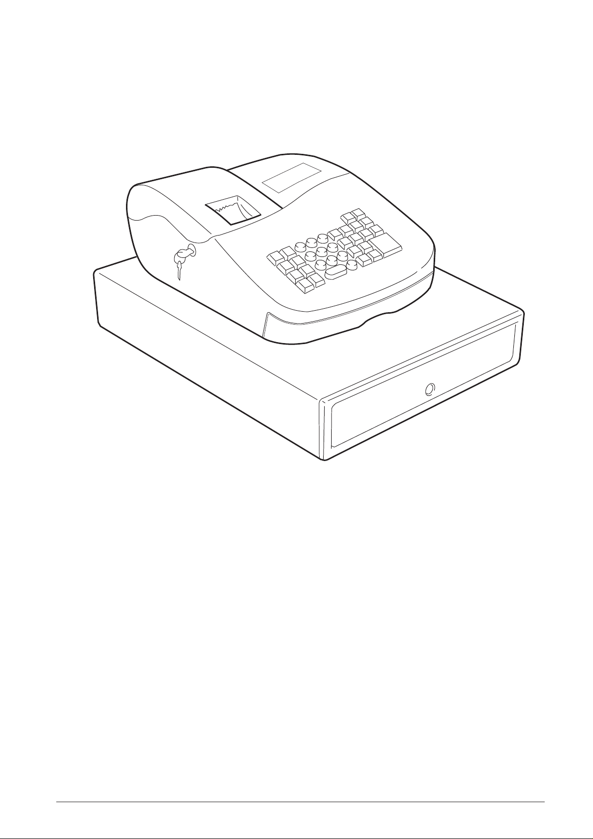
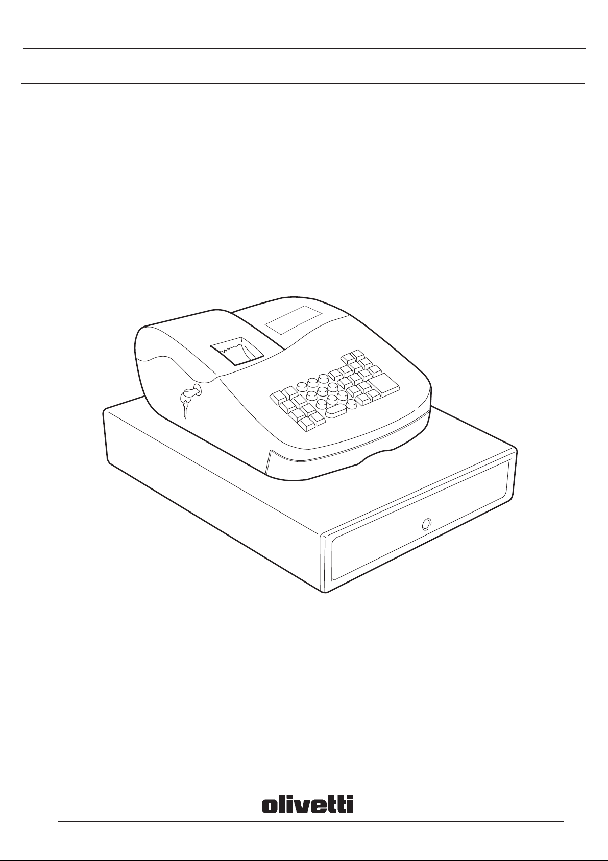
1. O VERVIEW
Fig. 1-1 Overall View of the Cash Register
686770R Service Manual 1-1
Page 8

1.1 TECHNICAL SPECIFICATIONS
Type: Electronic cash register with 8 departments
Display: Bright double display with 16x6 mm numbers, error symbol, change, subtotal, minus,
total and quantity
Display capacity: 9 digits
Printer: ECR exclusive serial printer
Paper supply: 57 mm wide wood-free single ply tape
Memory protection: Approx. 3 months after power interruption with 4 1.5 V Mignon batteries
Technology: CMOS RAM
Power supply: AC Adapter
Internal Battery
Line voltage: 220 V
Power consumption: Stand-by 2.2 W; operating 4 W
Operating temperature: 0° to 40° C
Dimensions: Depth 425 mm, Width 325 mm, Height 210 mm
Weight: Approx. 6 Kg
1-2 Service Manual 686770R
Page 9

2. SPECIFICA TIONS AND
OPERATING PRINCIPLES
2.1 SPECIFICATIONS
2.1.1 FEATURES
Paper (supplied by the user)
Type: Regular paper roll
Size: Width 57.5 mm ± 0.5 mm
Roll diameter: 80 mm or less
Thickness: 0.06 ~ 0.085 mm
Average weight: 47 g/m2 ~ 64 g/m2 (40 ~ 55 kg/
1000 sheets/1091 x 788 mm)
The Micro Printer is designed for use with calculators.
It offers the following features:
• Ultra-compact and lightweight design.
• Movable type for sharp printing quality.
• High printing speed using a mechanism that can
return the carriage from any column position.
• Silent printing.
• Quick feeding and paper free functions.
• Can run on size AAA manganese batteries (low-
power drive).
• Uses ordinary paper.
• Requires no motor speed control.
2.1.2 SPECIFICATIONS
The main printer specifications are listed below.
Print method
Serial printing with movable type
Carriage width
Maximum of 13 printable columns (including 2 symbol
columns)
Character position
On symbol column side: 12 positions + 2 empty
positions
On numeric column side: 14 positions
Character size
1.6 (W) x 2.8 (H) mm
Intercharacter intervals
Between numerics: 2.1 mm
Between a numeric and a symbol: 2.6 mm
Paper feeding
Typically 4.3 Ips. Fast paper feeding is also possible,
and a paper release mechanism is provided.
Inking
Ink roller method
Ink roller life: 700,000 characters
Standard: IR-30 (IR-40 is also applicable)
Motor
Terminal voltage: 6.0 VDC
Average current: Approximately 0.14 A
(during 13-column, 7-character
shift printing at 6.0 VDC,
25°C/77°F)
Sensor
Mechanical point of contact
Reset signal R, Timing signal T, and Sub-timing
signal t
Trigger coil (electromagnet)
Terminal voltage: 6.0 VDC
D.C. resistance: 16.7 Ω (at 25°C/77°F)
Connection method
Jumper wire on printer side
Guaranteed operating temperature
0° - 40°C / 32° - 104°F
(guaranteed printing temperature:
5° - 40°C/41° - 104°F)
Reliability
MCBF: 300,000 columns
Line spacing
4.6 mm
Print speed
Average printing speed at 6.0 VDC, 13-column printing:
Typically 0.7 I/s
6-column printing: Typically 1.4 I/s
686770R Service Manual 2-1
External dimensions
86 (W) x 58.4 (D) x 19 (H) mm
(3.39 (W) x 2.30 (D) x 0.75 (H) inch)
Weight
Approximately 80 g (0.21Ib)
Page 10
2.1.3 MECHANISMS
This printer consist of two print wheels, a hammer, and
a carriage equipped with an ink roll. It is a serial printer
with movable type, and it prints by sequentially moving
the carriage across from the lowest-order column.
When the motor is activated, the gear trains rotate and
cause the print wheels and detection wheel to rotate.
When the trigger coil charged by a signal (corresponding
a character) output from the sensor, a character is
selected, the print wheel stops, the print gear is rotated
by the action of the planet gear, and a character is
printed.
The carriage then shifts to the next column (columnshift operation). When charge to the trigger coil is
extended during character selection at the end of a line,
printing is performed and the carriage is returned to the
initial column. The paper is then fed forward to complete
the printing of one line.
This printer consist of five mechanism: the transmission
and select, defection, print, inking, and paper feeding.
Fig. 2-1 shows an external view of the Micro serial
Printer. For details on the operating principles and
handling of each mechanism, see Subsection
2.2
Operating Principles
and Maintenance
.
, and Chapter 3
Handling
Fig. 2-1 Exterior View
2-2 Service Manual 686770R
Page 11
2.2 OPERATING PRINCIPLES
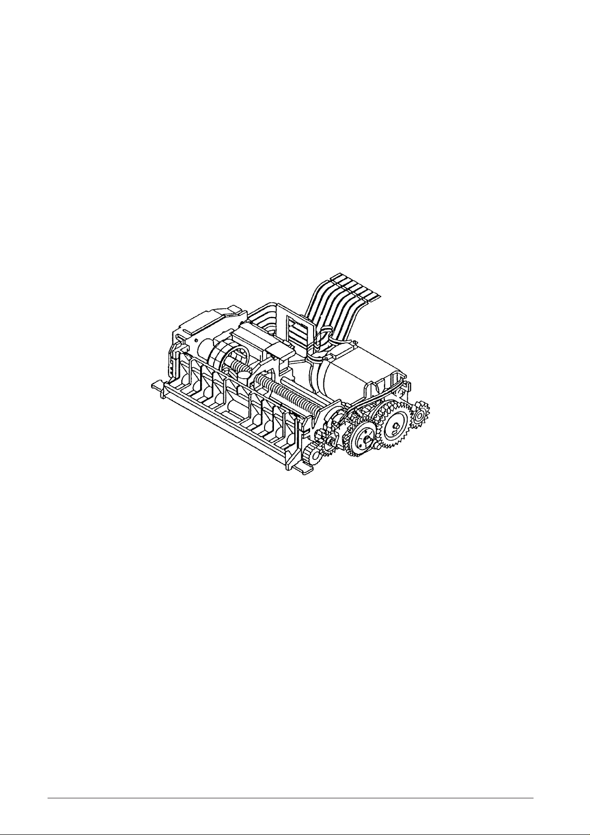
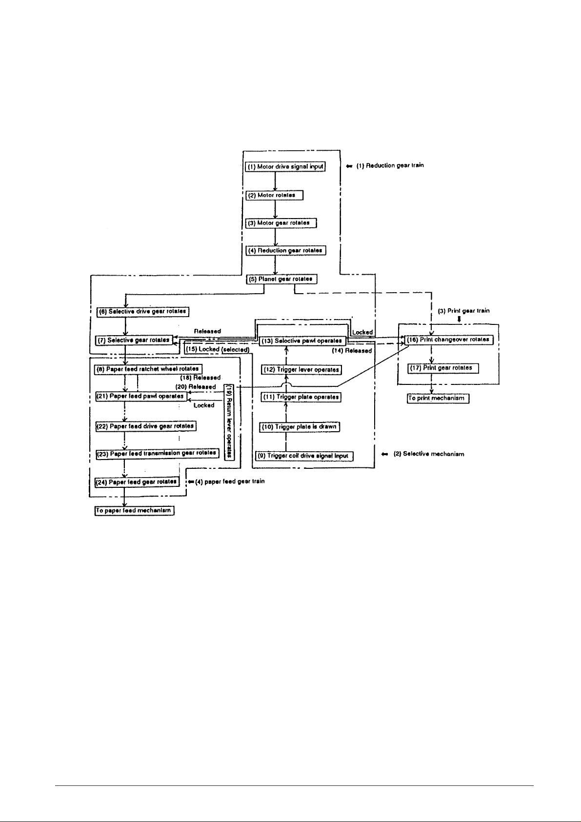
2.2.1 TRANSMISSION/SELECT MECHANISM
As shown in Fig. 2-2, this mechanism consists of the reduction gear train, and paper feed gear train.
Fig. 2-2 Transmission/Select Mechanism
686770R Service Manual 2-3
Page 12
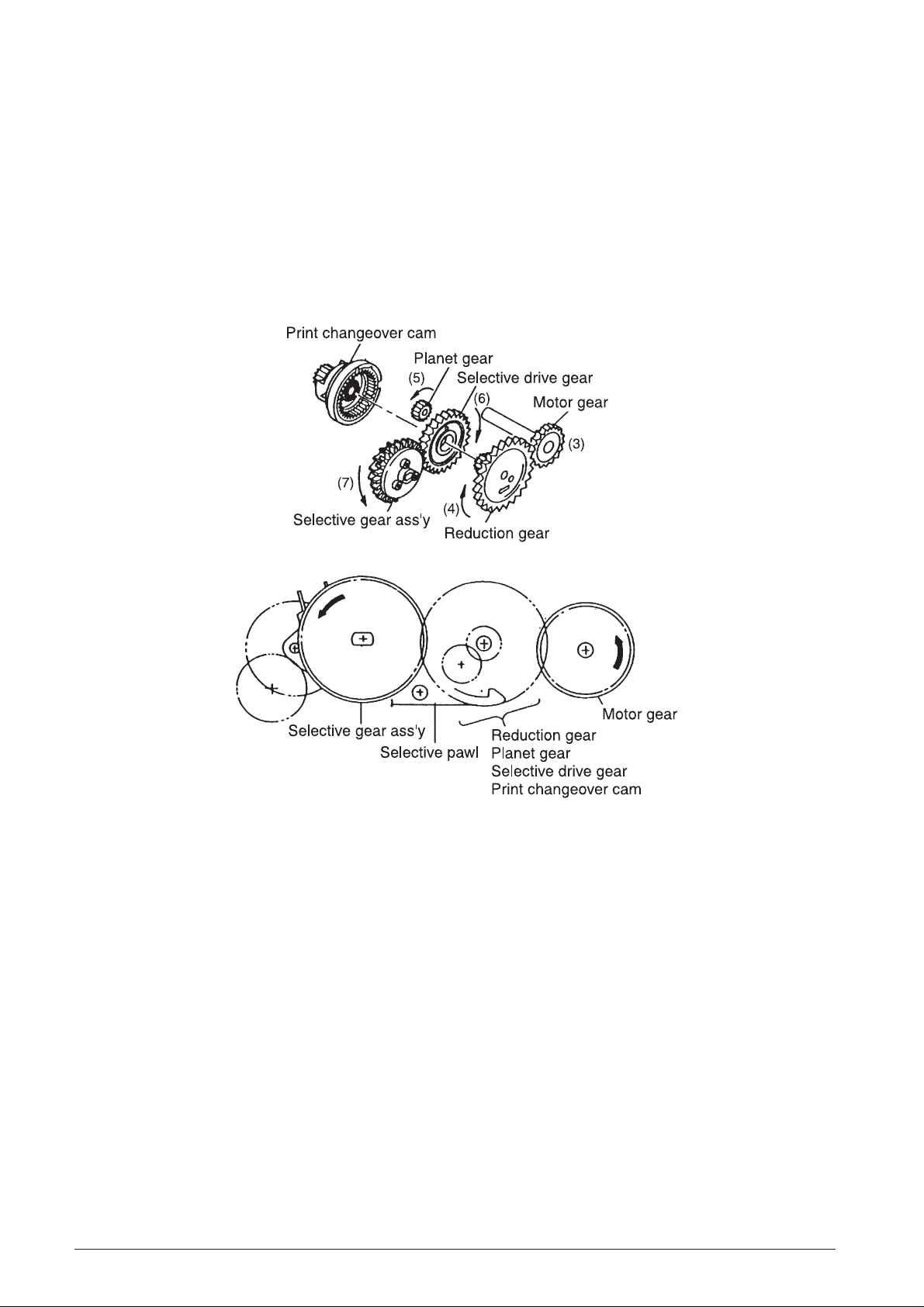
Reduction gear series
(See Fig. 2-2 and 2-3)
The reduction gear train consists of the motor gear,
reduction gear, planet gear, selective drive gear,
selective gear assembly, selective pawl, and print
changeover cam. When the motor rotates (2), the
rotational force is sequentially reduced from the motor
gear (3) on the same shaft through the gear train to the
selective gear assembly (7).
The rotation of the print changeover cam is locked by
the action of the selective pawl, so the paper feed
ratchet wheel (8) on the same shaft as the selective
gear assembly, the print wheel, and the detection
wheel also rotate at the same time.
Fig. 2-3 Reduction Gear Series
2-4 Service Manual 686770R
Page 13
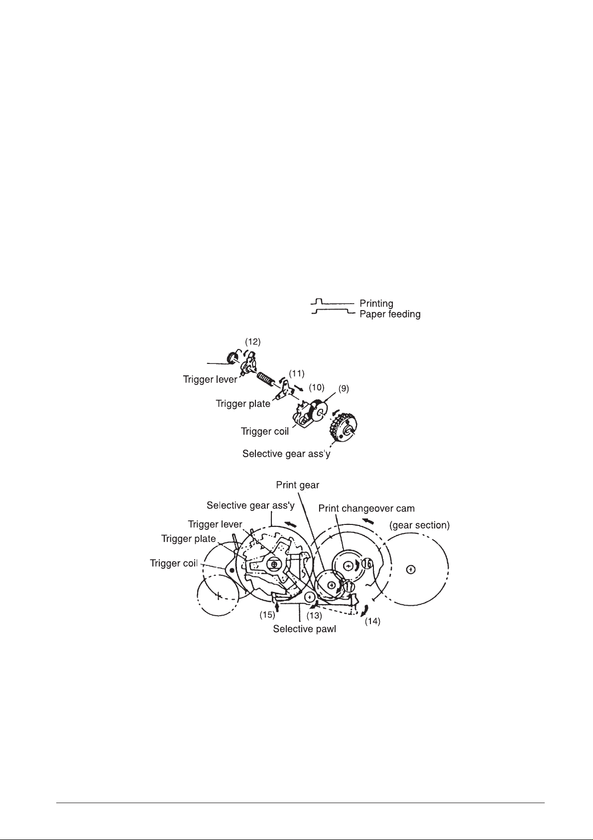
Select mechanism
(See Fig. 2-2 and 2-4)
As shown in Fig. 1-4, the select mechanism consists
of the selective gear assembly, trigger coil, trigger
plate, trigger lever, and selective pawl. The select
mechanism operates during rotation of the reduction
gear series. When a drive signal is input (9) to the
trigger coil in conformance with the timing signal output
from the sensor, the trigger plate is drawn (10) to the
yoke fixed on the selective gear assembly so that the
trigger plate (11), trigger lever (12), and selective pawl
(13) rotate together with the selective gear assembly.
At the same time as the print changeover cam is
unlocked, the selective pawl locks (15) the tooth
section corresponding to the character of the selective
gear assembly. When the selective gear assembly is
stopped, the print wheel mounted on the same shaft
also is stopped, and the character selected.
Print gear series
(See Fig. 2-2 and 2-4)
The print gear series consists of the print changeover
cam and the print gear. When the selective gear
assembly is stopped by the select mechanism, the
interlocked selective drive gear is also stopped. At the
same time, the unlocked (14) print changeover cam is
coupled and is rotated (16) by the planet gear of the
totalling reduction gear series. The print gear thus
rotates (17) and transmits its movement to the printing
mechanism.
Fig. 2-4 Select Mechanism and Print Gear Series
686770R Service Manual 2-5
Page 14
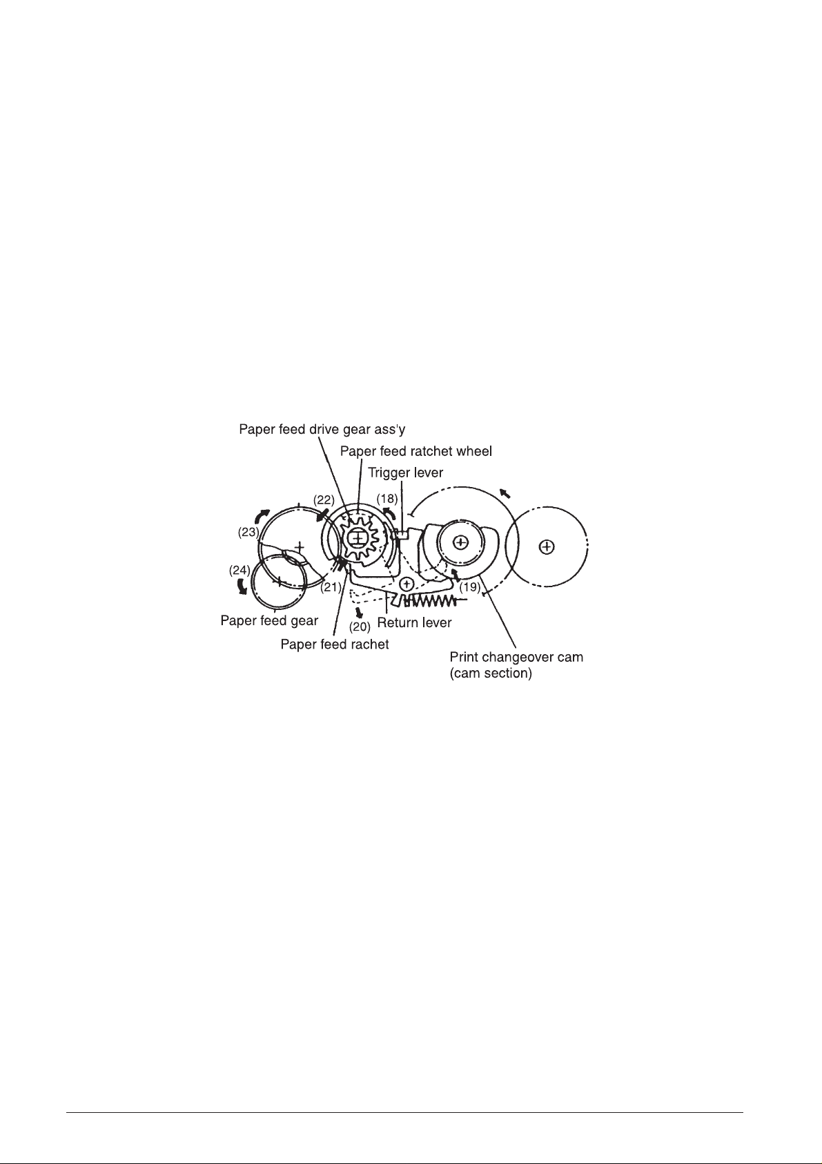
Paper feeding gear series
(See Fig. 2-2 and 2-5)
As shown in Fig. 2-5, the paper feeding gear series
consists of the paper feed ratchet wheel, paper feed
ratchet, paper feed drive gear assembly, paper feed
transmission gear, and paper feed gear.
During column selection or consecutive paper feeding,
the select mechanism and printing gear series operate
by extending the trigger coil drive signal at the first
column during space selection. However, the return
lever and trigger lever are unlocked (18) to maintain the
operation of the trigger plate and trigger lever. When the
print changeover cam rotates, the cam controlling the
return lever reaches a notched section. The return
lever is thereby released and beings operating (19) due
to spring force, and its interlocking with the paper feed
ratchet is cancelled (20).
The paper feed ratchet on the paper feed drive gear
assembly operates (21) due to spring force and
meshes with the teeth of the paper feed ratchet wheel
on the same shaft as the selective gear.
When printing operation is completed, the print
changeover cam causes the selective pawl to return to
its pre-selection status, and the print changeover cam
is stopped. When the selection gear begins rotation,
the paper feed drive gear assembly (22), paper feed
transmission gear (23), and paper feed gear (24) all
rotate together with the paper feed ratchet wheel. This
movement is then transmitted to the paper feeding
mechanism.
Fig. 2-5 Paper Feeding Gear Series
2-6 Service Manual 686770R
Page 15
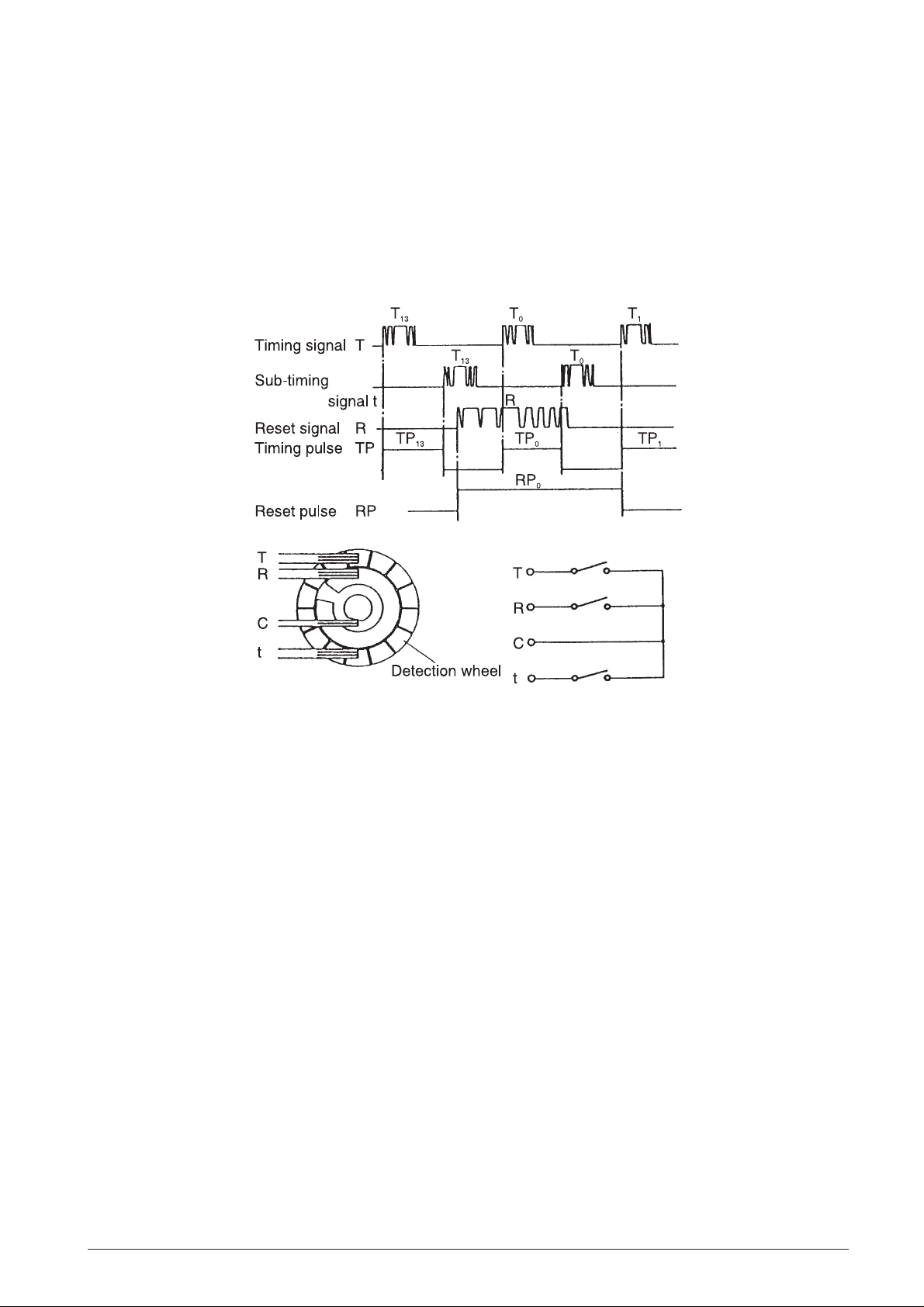
2.2.2 SENSOR MECHANISM
(See Fig. 2-6)
The sensor mechanism consists of the sensor as-
sembly and the sensor gear. The sensor employs a
mechanical contact-point system and generates a
timing signal T and a sub-timing signal t in correspondence to each character position on the print
wheel.
The sensor also generates a reset signal at each
rotation of the print wheel. Waveform rectification of
these signals should be performed by the user, as
timing or reset pulses.
Fig. 2-6 Sensor Mechanism
686770R Service Manual 2-7
Page 16
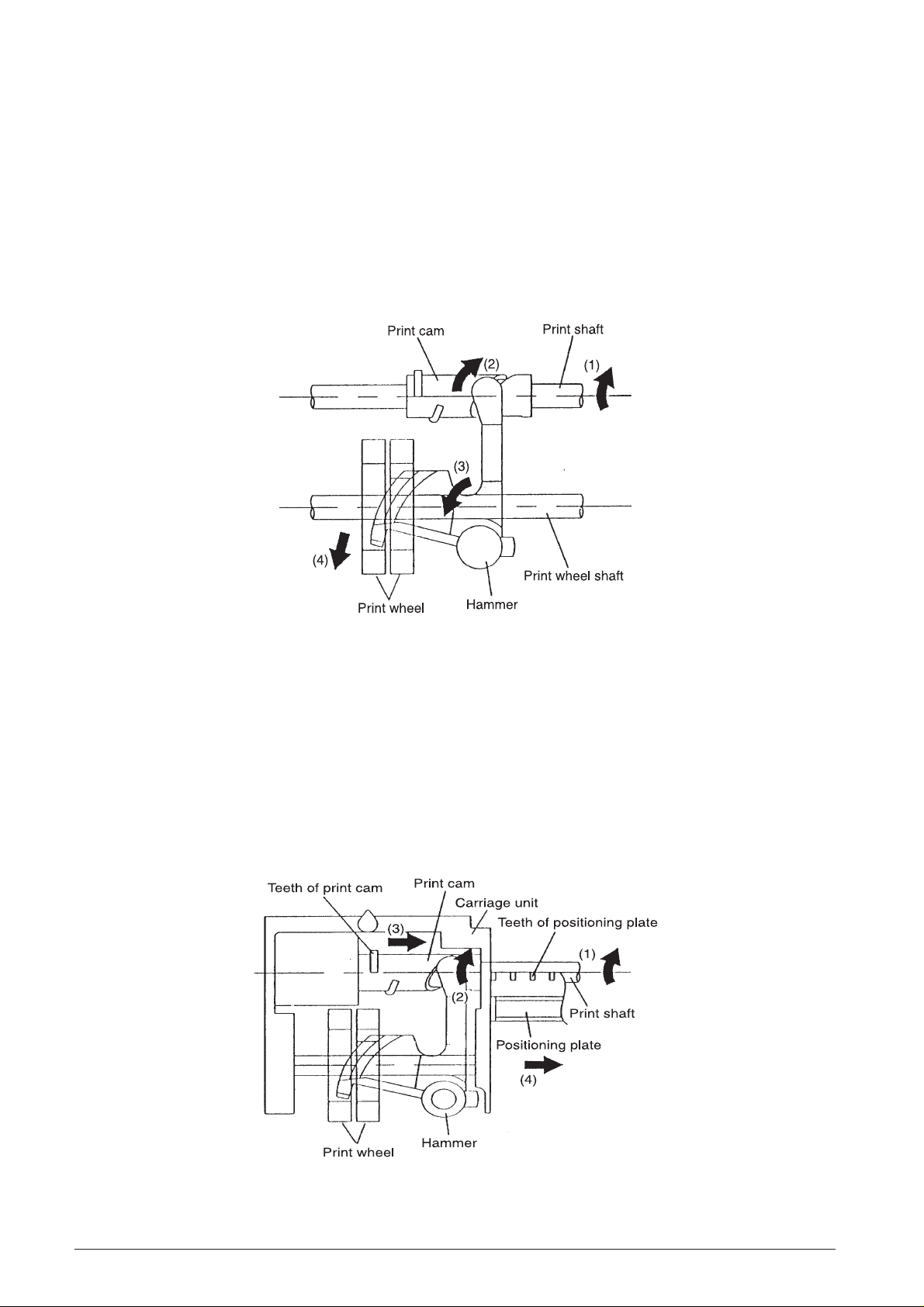
2.2.3 PRINT ING MECHANISM
The printing mechanism performs two operations:
printing and carriage movement.
Printing operation
(See Fig. 2-7)
When the print gear series (see Subsection 2.2.1,
Transmission/Select Mechanism)
shaft and print cam to rotate in the direction of a
arrows (1) and (2), the hammer rotates in the direction
of ➡ arrow (3).
causes the print
Thus, the print wheel is pressed in the direction of ➡
arrow (4) by the hammer, and printing is performed.
The print wheel, similar to the print changeover cam,
rotates once with each printing operation, and printing
is performed during the first half of the print shaft
rotation.
Fig. 2-7 Printing Operation
Carrying operation
(See Fig. 2-8)
Carrying is performed after printing, during the sec-
ond half of the print shaft rotation. As soon as the
positioning plate begins rotating the print gear, the
cam section of the print gear unlock its meshing the
return lever, and the print gear meshes with the print
cam.
When the print shaft rotates in the direction of ➡ arrow
(1), the meshing between the teeth of the print cam
and the teeth of the positioning plate causes the print
shaft to slide in the direction of ➡ arrow (2) while
rotating in the direction of ➡ arrow (3). The simultaneously with this carriage unit is carried sliding action
(➡ arrow (4))
Fig. 2-8 Carrying Operation
2-8 Service Manual 686770R
Page 17
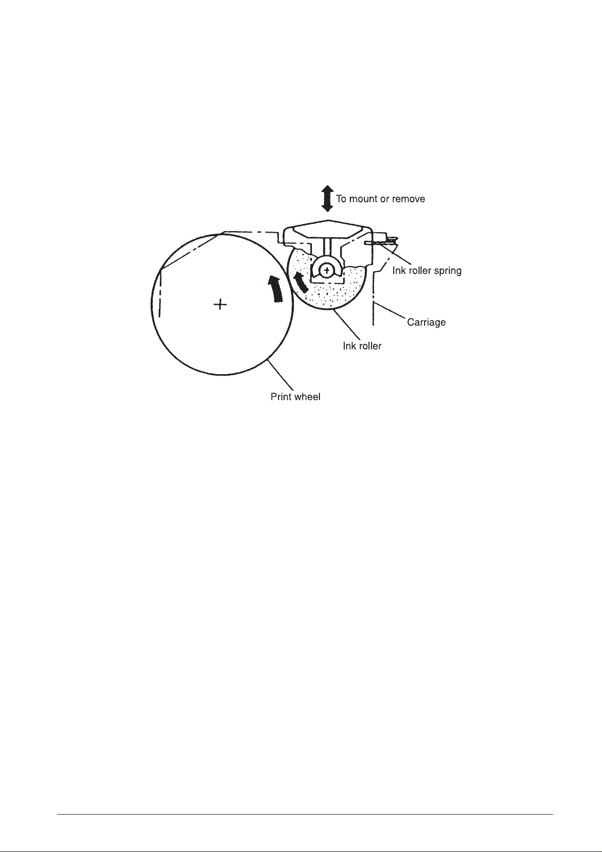
2.2.4 INKING MECHANISM
(See Fig. 2-9)
The ink roller is held lightly against the other periphery
of the print wheel by the force of the ink roller spring.
When the print wheel rotates, the ink roller also
rotates and supplies ink to the wheel.
Fig. 2-9 Inking Mechanism
686770R Service Manual 2-9
Page 18

2.2.5 PAPER FEEDING MECHANISM
The paper feeding mechanism performs two operations: carriage return and paper feeding.
Carriage return operation
(See Fig. 2-10)
The paper feeding gear series (see Subsection 2.2.1,
Transmission/Select Mechanism
lever to drop into the cam section of the print
changeover cam so that it meshes with the positioning plate (➡ arrow (1) and (2)).
) causes the return
The rotation of the print changeover cam restores the
return lever to its original position (➡ arrow (3)) and
rotates the positioning plate with which it is meshed
(➡ arrow (4)).
As a result, the teeth of the positioning plate and print
cam are disengaged (5), and the force of the print
wheel spring and carriage spring returns the carriage
(➡ arrow (6)).
Fig. 2-10 Carriage Return Operation
2-10 Service Manual 686770R
Page 19

Paper feeding operation
(See Fig. 2-11)
Paper is feed while the paper feed drive gear assem-
bly performs one rotation. When the paper feeding
gear series (see Subsection 2.2.1,
Select Mechanism
rotate in the direction of ➡ arrow (1), the paper feed
roller within the platen also rotates in the direction of
➡ arrow (2), and the paper is fed by friction between
the paper hold roller and the paper feed roller.
) causes the paper feed gear to
Transmission/
When the paper feed ratchet within the paper feed drive
gear assembly strikes the return lever, it disengages
from the paper feed ratchet wheel, the rotation of the
paper feed drive gear assembly stops, and paper
feeding terminates.
Fig. 2-11 Paper Feeding Operation
686770R Service Manual 2-11
Page 20

2.2.6 PRINT CYCLE INITIALIZATION
To confirm that carriage is in stand-by status (at the
first column), initialization must be performed prior to
printing and paper feeding. Initialization is completed
by performing a line feed. The following paragraphs
describe printer timing operations for printing and
paper feeding.
Printing of the first line
1) The Timing pulses TP are counted after the motor
drive signal is applied and the motor is activated.
The reset pulse RP appearing after eight timing
pulses is regarded as RPo, and the first timing
pulse TP after RPo rises is regarded as TPo.
2) Character selection (first column)
The trigger coil drive pulse is applied to the trigger
coil during the interval from timing pulse TPn to
TPn + 1 which corresponds to the desired character. At that time, the timing pulse interval (TPn to
TPn +1) is measured to obtain TW1. Following
character selection, the print wheel stops (the
timing pulse retains the TPn + 1 status). Printing
and carrying are then automatically executed.
3) Character selection (second column and onward)
The print wheel starts rotating again and the first
timing pulse is TPn +2. Character selection can be
performed from next timing pulse TPn + 3. The
rest of the character selection operation is identical to that described in step 2) above.
4) Carriage return and paper feeding
During character selection for the highest-order
column of a line of print, printing, carriage return,
and paper feeding are performed by adding: [the
width of the drive pulse to the trigger coil] + [the
timing pulse interval TW2 (TPn to TPn + 1) at that
time] + [(the TP interval TW1 measured during the
selection of the first column) x 6].
5) Motor off
After completing the highest order printing in one
line, the print wheel begins to rotate and timing
pulse TP is generated. Counting from this initial
rising pulse, the motor drive signal is cut off at the
rise of the 14th timing pulse TP.
NOTE:
• The first timing pulse generated after the print
column-shift process (TPn + 2) cannot be used for
character selection.
Consecutive printing
1) The process for printing the initial line similar to
that for “Printing the first line” above.
2) Printing of second and later lines begins as
follows:
After printing the first line, the following pulses TP
are counted with the motor still driven. Printing of
the first column of the second line then begins at
the rise of the 14th timing pulse in cases where the
number of columns in the first line is 7 or less,
otherwise, printing begins at the 21st timing pulse.
The same procedures as those in steps 2) to 4) of
“Printing the first line” above are then performed.
3) Consecutive printing is performed by repeating
step 2) above.
4) Motor off
Step 5) of “Printing the first line” above is per-
formed.
Paper feeding for the first line
1) The timing pulses TP are counted after the motor
drive signal is applied and the motor is activated.
The reset pulse RP appearing after eight timing
pulses is regarded as RPo, and the first timing
pulse TP after RPo rises is regarded as TPo.
2) Paper feeding
The empty character TP10 is selected. At that
time, the timing pulse interval TP10 to TP11 is
measured to obtain TW1. When the width of the
trigger coil drive pulse equals the measured TW1
plus six times TW1, the empty character on the
print wheel is selected and the paper is fed.
3) Motor off
After the paper is fed for one line, the print wheel
begins to rotate. Counting from the initial rising
timing pulse, the motor drive signal is cut off at the
rise of the 14th timing pulse TP.
Fast paper feeding
1) The process for feeding the initial line is similar to
that for “Paper feeding for the first line” above.
2) Paper feeding for the second and later lines begins
as follows: after completing the paper feeding for
the first line, with the motor remaining driven, the
following timing pulses TP are counted. From the
rise of the 21st timing pulse, selection of the empty
character TP10 becomes possible. Step 2) of
“Paper feeding for the first line” above is then
performed.
3) Fast paper feeding is performed by repeating step
2) above.
4) Motor off
Step 3) of “Paper feeding for the first line” above
is performed.
2-12 Service Manual 686770R
Page 21

3. HANDLING, MAINTENANCE
3.1 HANDLING THE PRINTER
3.1.1 PRECAUTIONS ON PRINTER
HANDLING
Transport precautions
(See Fig. 3-1)
1 ) When transporting the printer, never carry it by the
jumper lead only.
2 ) Avoid impact to the printer by dropping, striking it,
or collision with another printer.
Fig. 3-1 Proper Handling of Printer
Storage precautions
• Avoid storage in locations exposed to excessive
dirt, dust, moisture, or in direct sunlight.
• For long-term storage (over one month), place the
printer in a polyethylene bag after wrapping it in
anti-rust (VPI) paper, then store it in a dry location.
686770R Service Manual 3-1
Page 22

Use precaution
• Since the printer employs a permanent magnet (in
the motor section), avoid using it in locations
exposed to excessive iron filings, dirt, dust, or
other foreign particles.
• Never use the printer without the paper and ink
roller installed.
• Make sure to use only the specified paper and ink
roller.
• The ink roller is a disposable part; do not attempt
to refill its ink supply.
3.1.2 PAPER INSTALLATION
Loading the Paper
When loading the paper into the printer, make sure to
heed the following points.
Paper insertion
Insertion the paper into the printer with the paper roll
positioned as shown in Fig. 3-2.
Paper insertion precautions
• Insert the paper straight into the paper entrance.
Never insert paper having an uneven leading
edge; never insert paper at a slant.
• Push the paper in the feeding direction to make
insertion easier.
Removing the paper
Remove the paper by following one of the two methods below:
• Perform paper feed using an electrical operation:
Switch on the printer, press the Paper Feed button,
and remove the paper.
• The paper release mechanism in stand-by status
allows the paper to be freely removed by pulling it
out the printer. Pulling out the leading edge of
the paper at a slant may cause jamming.
Fig. 3-2 Paper Insertion
Leading edge of the paper roll
The leading edge of the paper from the paper roll should
be cut straight as shown in Fig. 3-3.
Fig. 3-3 Leading Edge of the Paper Roll
3-2 Service Manual 686770R
Page 23

3.1.3 INK ROLLER INSTALLATION
Mounting the Ink roller
(See Fig. 3-4)
• Place the ink roller in the cutout sections of the
carriage, then press down gently until it clicks into
place.
Fig. 3-4 Ink Roller Installation
Replacing the ink roller
(See Fig. 3-5)
• Press the knob of the ink roller in the direction of
the ➡ arrow, then lift the ink roller up and out of the
carriage.
Fig. 3-5 Ink Roller Replacement
686770R Service Manual 3-3
Page 24

3.2 MAINTENANCE
3.2.2 INSPECTION
To prevent potential trouble, make sure cleaning and
inspection is carried out according to the points described in the following subsections, depending on the
environment in which the printer is used.
3.2.1 CLEANING
Eliminating dirt or stains
Wipe off soiled areas using alcohol or benzene.
Eliminating dust, scraps, and other foreign particles
Use a vacuum cleaner to carefully draw out all foreign
particles from every area of the printer.
NOTES:
Never use thinner, tricholyene, or ketone solvent as
they may deteriorate or damage plastic parts. Check
the lubricant remaining in each cleaned area and
perform lubrication as required (see Subsection 3.3.2,
Lubrication Points
).
3.3.2 LUBRICATION POINTS
Check the printer to see if it is being operated properly
and if it is being maintained in optimum condition. If
any unsatisfactory points are discovered, they should
be remedied. In particular:
• Make sure that the ink roller is securely installed
in the carriage.
• Make sure that the ink roller in use conforms to the
specifications. Check the ink roller for damage,
and replace it if it is affecting print quality.
3.3 LUBRICATION
3.3.1 LUBRICANT TYPES
The types of oil used greatly influence the performance and durability of the printer, especially at low
temperatures.
No. Lubrication Point Oil Type
(1) Contact point between selective gear assembly and trigger plate O-3
(2) Contact point between print shaft and frame (2 points) O-3
(3) Outer surface of print shaft O-3
(4) Outer surface of print wheel shaft O-3
(5) Contact point between print cam and hammer spring O-3
(6) Contact point between print cam and the positioning plate O-3
(7) Contact point between positioning shaft, frame, and return lever (3 points) O-3
(8) Contact point between reduction gear and the E-ring O-3
(9) contact point between selective drive gear and reduction gear O-3
(10) Contact point between selective pawl and print changeover cam O-3
3.3.3 LIST OF LUBRICANTS
Item Designation Volume
Oil O-3 40 gm
Grease G-34 40 gm
3-4 Service Manual 686770R
Page 25

3.4 PROBLEM RESOLUTION
In general, the printer should be replaced when problems arise. Depending on the particular problem, however,
the printer may be easily repaired. Therefore, take necessary corrective actions according to the following table.
In the case of problems for which no corrective actions exist in this table, the printer should be replaced.
686770R Service Manual 3-5
Page 26

3-6 Service Manual 686770R
Page 27

3.5 PRINTER PIN ASSIGNMENTS
Fig. 3-6 illustrates the pin assignments of the printer
circuitry.
NOTE:
The printer sensor side is regarded as “1”.
Fig. 3-6 Pin Assignment Diagram
686770R Service Manual 3-7 .
Page 28

Page 29

3.6 TIMING CHART
686770R Service Manual 3-9.
Page 30

Page 31

4. DISASSEMBLY PROCEDURE/HOW TO LOCATE THE ASSEMBLIES
Fig. 4-1 Cash Register Front View
4.1 HOW TO LOCATE THE POWER ASSEMBLY
Fig. 4-2 Cash Register Rear View
686770R Service Manual 4-1
Page 32

4.2 THE REMOTE BATTERIES/
LOCATION OF ON/OFF SWITCH
• Remove the cover (1).
• Remove the paper roll and roll holder.
• Remove the battery housing cover (2) in the direc-
tion of the arrow.
Fig. 4-3 Locating the Battery Compartment and Printer Cover
Fig. 4-4 Locating the ON/OFF Switch
4-2 Service Manual 686770R
Page 33

4.3 MACHINE DISASSEMBLY REASSEMBLY
4.3.1 MACHINE CASE
Disassembly
• Unplug the machine power cord from the electrical
wall outlet.
• Loosen screw (1)
• Push the case of the machine (2) in the direction of
the arrow (3).
• Remove the case (2) by lifting it the direction of
arrow (4).
Reassembly
• Correctly position the case on the machine.
• Push the case (1) in the direction of arrow (5).
• Tighten screw (1).
• Plug the machine power cord into the electrical wall
outlet.
Fig. 4-5 Machine Case Disassembly/Reassembly
4.3.2 PRINTER UNIT
Disassembly
• Remove the printer compartment cover (1).
• Remove the machine case (2).
• Disconnect connector (3).
• Using a screwdriver, remove screw (4) that secures
the paper support (5) and remove this support.
• Remove the printer (6) in the direction of the arrow
shown being careful to avoid damaging the
connection cables.
Reassembly
• Correctly position the printer (6) as shown in the
figure.
• Correctly position the paper support (5) and tighten
its related securing screw (4).
• Reattach the connector (3).
• Refit the case of the machine (2) and the printer
compartment cover (1).
Fig. 4-6 Printer Unit Disassembly/Reassembly
686770R Service Manual 4-3
Page 34

4.3.3 MAIN BOARD AND DISPLAY
Disassembly
• Remove the machine case.
• Disconnect the printer connector (1).
• Disconnect the paper feed motor connector (2).
• Disconnect the keypad connectors (3).
• Disconnect the battery supply connectors (4).
• Disconnect the power supply connector (5).
• Disconnect the battery supply
connector (6).
• Using a screwdriver, remove the securing
screws (7).
• Remove the main board (8).
Reassembly
Perf orm the disassembly procedure in reverse order .
Fig. 4-7 Main Board and Display Disassembly/Reassembly
4.3.4 PAPER FEED MOTOR
Disassembly
• Remove the machine case.
• Disconnect the motor power supply connector (1).
• With a screwdriver, remove securing screws (2).
• Remove motor (3) with its related support (4).
Reassembly
• Correctly position motor (3).
• Tighten securing screws (2).
• Reconnect the motor power supply connector (1).
• Refit the machine case.
Fig. 4-8 Paper Feed Motor Disassembly/Reassembly
4-4 Service Manual 686770R
Page 35

4.3.5 BATTERY COMPARTMENT
Disassembly
• Remove the machine case.
• Remove the securing screws (1).
• Remove the battery compartment.
Fig. 4-9 Battery Compartment Disassembly/Reassembly
4.3.6 KEYP AD
Reassembly
• Perform the disassembly procedure in reverse
order.
Disassembly
• Remove the machine case.
• Disconnect the keypad - main board connectors (1).
• Using a screwdriver, remove securing screws (2).
• Remove the keypad (3) together with the machine’s
ON/OFF switch (4).
Reassembly
• Correctly position the keypad (3) and the ON/OFF
switch (4).
• Tighten the securing screws (2).
• Restore connection (1).
• Refit the machine case.
Fig. 4-10 Keypad Disassembly/Reassembly
686770R Service Manual 4-5
Page 36

Page 37

5. BLOCK STRUCTURE CHART
As illustrated in the Chapter 6.
5.1 CIRCUITRY
Functions in each circuit is explained below block by
block.
• Block A: Display Control
LCD driver is included in the main CPU and is
directly driven by ports below.
* COM 0 - COM 1 - COM 2
* SEG 0 - SEG 25 - SEG 32 - SEG 33
LCDs are 1/3 duty,1/2bias.
• Block B: Scan Signal for Key switch, Mode
switch and Paper feed key:
Scan Signal Output Ports: from ports P07 - P12P60 and P61 , by High-active scan output.
Key switch: when P54 - P57 are depressed, they
are accepted as return input of the key matrix.
Mode lock switch and Feed key: P53 is read in as
a return input.
* To prevent input errors caused by chattering,
data will be read twice before accomplishing key
input.
• Block E: Buzzer:
When Port P45 gets high, oscillating signals programmed at NAND gate make transistor 2SA2603
on/off and make the buzzer buzz.
• Block F: Reset Circuit:
Reset IC works to reset main CPU.
• Block G: Black-Out Detection Signal:
Blackout signal is generated when voltage in Vcc
line drops to 3.0 V. This signal gets “low” at the
time of blackout and is transferred to Port 42 for
CPU to dispose it. Once blackout is detected, X
IN halts and only X CIN oscillates to turn the cash
register for electric consumption mode. Backup
currency at this time is about 10-40 uA.
• Block H: Printer Control:
• Motor Drive: P51 (low active)
• Printing Trigger: P50 (low active)
• Timing Signal: P43
• Reset: P44
NOTE:
Waveforms for timing signals and reset signals
are shaped by flip-flop at NAND gate.
• Block I: Circuitry:
This machine operates both by dry batteries and
with use of AC adaptor. Inserting an adaptor jack
automatically disconnect the battery circuit.
Voltage at each power line is as follows (at rated
voltage input).
VBB: 6.0 V (with backup)
Vcc: 6.0 V
Vprm: 6.0 V (when printer is not working)
V BB / V cc are provided via a stable circuit that
uses 3-terminal regulator (S81250HG).
NOTE:
1 ) Reset does not work when backup function is
working.
2) CPU needs to be reset at the first setting up,
otherwise normal operation would be hindered.
To secure normal operation, first install operation batteries worth OFF mode. Next turn the
key to REG1 mode, then place memory backup
batteries.
686770R Service Manual 5-1
Page 38

Page 39

6. SCHEMATICS AND DIAGRAMS
6.1 SYSTEM BLOCK DIAGRAM
Fig. 6-1 System Block Diagram
686770R Service Manual 6-1
Page 40

6.2 POWER SUPPLY CIRCUIT
Fig. 6-2 Power Supply Circuit
6-2 Service Manual 686770R
Page 41

6.3 RESET CIRCUIT
Fig. 6-3 Reset Circuit
6.4 POWER FAIL CIRCUIT
Fig. 6-4 Power Fail Circuit
686770R Service Manual 6-3
Page 42

6.5 DISPLAY CIRCUIT
Fig. 6-5 Display Circuit
6-4 Service Manual 686770R
Page 43

6.6 KEYBOARD CIRCUIT
Fig. 6-6 Keyboard Circuit
686770R Service Manual 6-5
Page 44

6.7 BUZZER CIRCUIT
Fig. 6-7 Buzzer Circuit
6.8 BATTERY CIRCUIT
Fig. 6-8 Battery Circuit
6-6 Service Manual 686770R
Page 45

6.9 PRINTER CIRCUIT
Fig. 6-9 Printer Circuit
686770R Service Manual 6-7 .
Page 46

Page 47

6.10SCHEMATIC DIAGRAM
686770R Service Manual 6-9.
Page 48

Page 49

7. ASSEMBLY CONSTRUCTION
686770R Service Manual 3-11
7-1.
Page 50

Page 51

REF. CODE DESCRIPTION
SPARE PAR TS CATALOGUE
IMPORTANT
This publication is written by TA TRIUMPH-ADLER Vertriebs GmbH (Service Department).
This document is the only document to which reference may be made for ordering spare
parts
Spare parts should be ordered at the following address: TA Triumph-Adler Vertriebs GmbH
Service Department
Fürther Straße 212
Nuremberg
November 1998
Subject to Alterations
686770R
Spare parts catalogue
TA Triumph-Adler Vertriebs GmbH
Fürther Straße 212
90429 Nürnberg
A - 1
Page 52

EXPLODED PARTS
REF. CODE DESCRIPTION
1
2
3
4
5
6
7
8
9
10
11
12
13
14
15
16
17
18
037498 N
037499 P
037500 U
037502 J
037503 K
037504 L
128710 D
037505 M
037506 N
037507 P
037508 Y
037509 Z
037510 M
037511 A
037512 B
037513 C
037514 D
037515 E
MAIN BOARD
M38203M4-374FP
DISPLAY LCO- B5180A
COMPLETE KEYBOARD ASSEMBLY
KEY DRAWER
PRINTER M31-041
MOTOR
DRAWER GROUP
COVER ASSEMBLY
PRINTER COVER
FRONT COVER
DEPOSIT DRAWER
WINDING REEL
BATTERY BOX
BATTERY COVER
DISPLAY FILTER
CAM LOCK KEYSET
AC ADAPTOR
A - 2
Spare parts catalogue
686770R
Page 53

EXPLODED PARTS
REF. CODE DESCRIPTION
17
10
16
9
3
4
15
2
14
1
18
13
7
11
5
6
686770R
12
Spare parts catalogue
8
A - 3
.
Page 54

Page 55

STST
AA
TT
A
AA
T
TT
UPDUPD
UPD
UPDUPD
O DI AO DI A
O DI A
O DI AO DI A
ST
STST
DATA PAGINE AGGIORNATE PAGINE CODICE
DATE UPDATED PAGES PAGES CODE
2/1999 1aEDIZIONE - 1st EDITION 55 686770R-00
GGIORNAMENTGGIORNAMENT
GGIORNAMENT
GGIORNAMENTGGIORNAMENT
AA
TING STTING ST
A
TING ST
AA
TING STTING ST
AA
TUSTUS
A
TUS
AA
TUSTUS
OO
O
OO
 Loading...