

Page 1
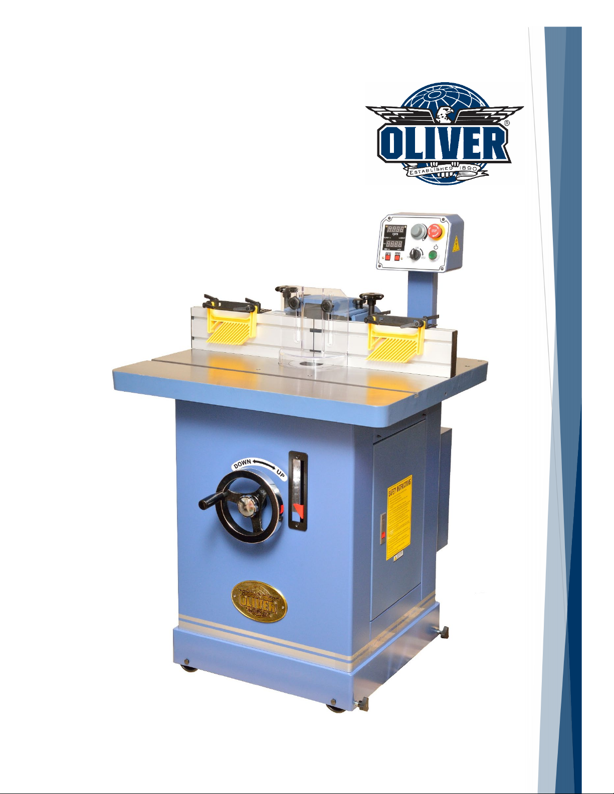
Shaper
Model 10047VS
Owner’s Manual
For Models Manufactured Since 06/2019
Oliver Machinery
WWW.OLIVERMACHINERY.NET
Stock Number: 10047VS.001
Manual Version: 1.0.0
1-800-559-5065
6902 S 194th St, Kent, WA 98032
Page 2

READ AND UNDERSTAND ALL INSTRUCTIONS IN THIS MANUAL BEFORE
ATTEMPTING TO ASSEMBLE OR OPERATE THE MACHINE.
FOLLOW THE INSTUCTIONS AND THINK SAFETY!
THE OWNER OF THIS MACHINE IS SOLELY RESPONSIBLE FOR THE SAFETY OF ANYONE USING
THIS MACHINE. SUCH RESPONSIBILITY INCLUDES BUT NOT LIMITED TO:
• PROPER ASSEMBLY, OPERATION, INSPECTION, MAINTENANCE, AND RELOCATION OF
THE MACHINE.
• PROPER TRAINING FOR THE OPERATORS AND ENSURES THIS MANUAL IS AVAILABLE
AT ALL TIMES.
• USAGE AUTHORIZATION.
• USAGE OF SAFETY AND PROTECTION DEVICE.
OLIVER MACHINERY DISCLAIMS ANY LIABILITY FOR MACHINES THAT HAVE BEEN ALTERED OR
ABUSED. OLIVER MACHINERY RESERVES THE RIGHT TO EFFECT AT ANY TIME, WITHOUT PRIOR
NOTICE, THOSE ALTERATIONS TO PARTS, FITTINGS, AND ACCESSORY EQUIPMENT WHICH THEY
MAY DEEM NECESSARY FOR ANY REASON WHATSOEVER.
** SAVE THIS MANUAL FOR FUTURE REFERENCES. **
PROP 65 NOTICE
WARNING: Drilling, sawing, sanding or machining wood products can expose you to wood dust,
and/or other chemicals known to the State of California to cause cancer, birth defects or other
reproductive harm.
Some examples of these chemicals are:
• Lead from lead-based paints.
• Crystalline silica from bricks, cement and other masonry products.
• Arsenic and chromium from chemically-treated lumber.
Avoid inhaling wood dust and other harmful chemicals. Use a dust mask and/or other safety
devices for personal protection.
For more information go to http://www.P65Warnings.ca.gov/wood
Page 3

Table of Contents
Introduction············································· 4
Specifications ·········································· 5
Identification ··········································· 8
Safety ·····················································10
General Safety Guidelines ························· 10
Safety Guidelines Specific to Shaper ·········· 12
Electricals ···············································14
Minimum Circuit Size Required for Model
10047VS Shaper ······································· 14
Grounding ················································ 14
Electrical Wiring ······································· 14
Setup ······················································15
Shop Preparation······································ 15
Receiving ·················································· 16
Inventory ················································· 17
Cleaning ··················································· 18
Dust Collection ········································· 18
Lock / Unlock Spindle Arbor ···························· 26
Install / Remove Spindle·································· 27
Install Shaper Cutter········································ 29
Installing/Removing Router Collets (Sold
Separately) ······················································ 31
Test Run ··················································· 32
Preparation for Wood Shaping ·················· 33
Material Selection and Inspection ·················· 33
Warped Stock ·················································· 33
Support Long Workpiece ································· 33
Safety Devices ················································· 33
Shaping Wood ·········································· 33
Shaping Long and Straight Pieces ···················· 33
Cross Grain Shaping Tips ································· 34
Shaping Tall Workpieces ································· 34
Shaping with Collars ········································ 34
Freehand Shaping············································ 35
Accessories ············································ 36
Maintenance ········································· 38
Inspect / Adjust Belt Tension ···················· 39
Replace Drive Belt ···································· 39
Spindle Elevator Adjustment ····················· 40
Moving / Leveling Machine ······················· 18
Controls and Operation ···························19
Control Panel Overview ···························· 19
Emergency Stop ·············································· 19
Magnetic Power Switch··································· 19
Machine Status Indicator ································ 19
Rotation Direction Switch ······························· 20
Spindle Speed Dial & Indicator ························ 20
Spindle Height Indicator ·································· 20
Spindle Height Adjustment ······················· 21
Fence Assembly ········································ 22
Fence Adjustments ··································· 23
Spindle Assembly Components and
Functionalities ········································· 25
Spindle / Cutter Setup ······························ 26
Troubleshooting ····································· 41
Wiring Diagram ····································· 44
Parts List ················································ 45
Table and Fence ······································· 45
Spindle Elevator Assembly ························ 46
Motor and Spindle ···································· 47
Cabinet and Control Panel ························ 48
Spindle & Miter Gauge ····························· 49
Maintenance Record ······························ 55
Notes ····················································· 56
Warranty and Service····························· 57
Page 4
Introduction
Thank you for choosing Oliver! This manual contains important information on how to safely set up,
operate, and maintain this machine. Please take the time to read through this manual, and make sure you
understand all instructions.
While this manual may provide tips on optimizing the result of your workpiece, the manual is not intended
as a substitute for formal woodworking training. If you need to know how to safely perform an operation,
please consult knowledgeable and qualified sources before proceeding further.
We made every effort to keep this manual up-to-date. Instructions, specifications, drawings, and
photographs in this manual should match the machine delivered. If you find any differences, or anything
that seems confusing in this manual, please check our website for an updated version:
WWW.OLIVERMACHINERY.NET/MANUALS
Alternatively, you can contact our technical support for help:
1-800-559-5065
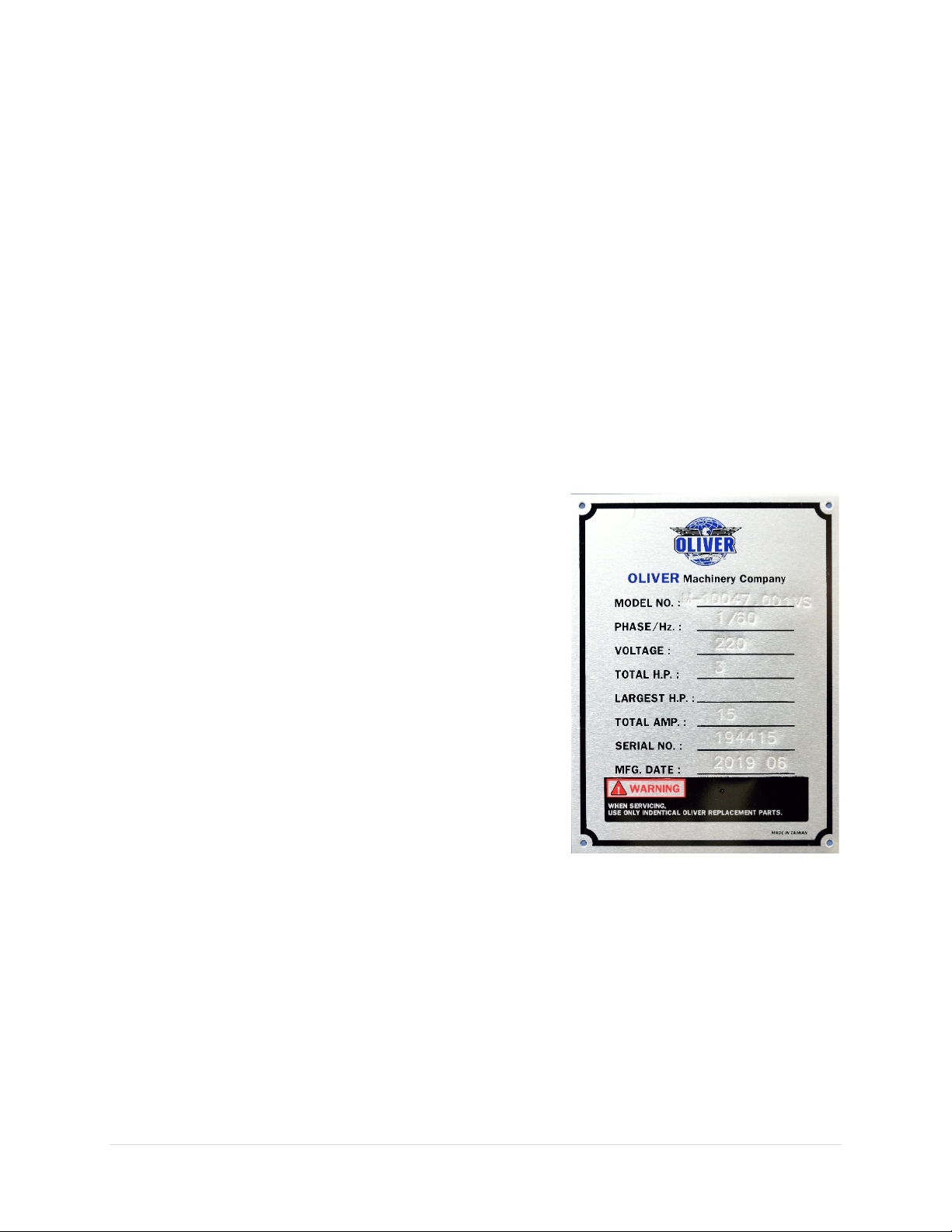
Before calling, please note down the manufacture date and serial
number of the machine. You can find the information on a
nameplate located on the back of the machine cabinet. This
information is needed to provide proper technical support, and
to determine if an updated manual is available for your machine.
Please let us know how well this manual serves you. If you have
any suggestions, please call the number above or email us at:
We love to hear from our customers and make improvements.
4 | Page Oliver Machinery 10047VS Shaper
Page 5

Specifications
Quick View
Model
10047VS Shaper
Stock Number
10047VS.001
Power Requirement
230V, 1Ph, 60Hz
Motor
TEFC 3HP, 230V, 3Ph
Max Spindle Under Nut Capacity
4” with 1-1/4” Spindle
Max Cutter Diameter Allowed
6-1/4” Below Table
Spindle Speed
5,000-10,000 RPM, Reversible
Dimensions
32-1/4“(W) x 32”(D) x 50”(H)
Footprint
22-3/4”(W) x 22-3/4”(D)
Fully Assembled Weight
396 lbs.
Warranty
1 Year (Motor and electronics)
2 Years (All other parts)
Product Dimensions
Width x Depth x Height (Fully Assembled)
32-1/4“(W) x 32”(D) x 50”(H)
Footprint
22-3/4” (W) x 22-3/4”(D)
Fully Assembled Weight
396 lbs.
Shipment Info
Type
Wood Crate with Pallet Base
Content
Shaper with Included Accessories
Dimensions
36”(L) x 35-1/2”(W) x 56”(H)
Weight
511 lbs.
Approx. Assembly Time
30 Minutes
Must Ship Upright
YES
Stackable
NO
Electricals
Power Requirement
230V, 1Ph, 60Hz
Full Load Current Rating
15A
Recommended circuit size
30A
Power Switch Type
Magnetic Switch with Overload Protection.
Connection Type
NEMA L6-30 Plug with 9.5’ 12AWG Cord
Overload Protection
Equipped
7” Above Table
10047VS Shaper OLIVERMACHINERY.NET 5 | Page
Page 6

Motor
Motor Type
TEFC
Horsepower
3HP
Power Requirement
230V, 3Ph, 60Hz
Full Load Current Rating
9A
Speed
3450 RPM (Max)
Efficiency / Power Factor
81% / 88%
Power Transfer Mechanism
Poly V-Belt and Pulleys
Bearing type
Permanently Sealed Ball Bearing
Spindle and Cutter
Spindle Sizes
1-1/4” (Included)
1/2", 3/4”, 1" (Optional)
Spindle Speed
5,000-10,000 RPM, Reversible
Vertical Spindle Travel
4"
Max Cutter (Under Nut) Capacity:
1/2" Spindle
2-3/4”
Max Cutter Diameter
6-1/4” Below Table
7” Above Table
Table
Material
Precision Ground Cast Iron
Table Dimensions
32-1/4“(W) x 26-3/4”(D)
Table Height
34-3/8”
Table Opening Diameter
6-1/4”
Number of Table Inserts
2
Table Insert Opening Diameter:
4-5/16”(Large)
2-1/2” (Small)
Miter Slot Type
T-Slot (Standard Size)
Miter Slot Width
3/4”
Miter Slot Height
3/8”
Power feeder mounting locations
On both rear corners of shaper table.
3/4” Spindle
1” Spindle
1-1/4” Spindle
3-1/2”
3-1/2”
4”
6 | Page Oliver Machinery 10047VS Shaper
Page 7

Fence
Material
Extruded Aluminum
Fence Length
16”, for each infeed and outfeed fence
Fence Height
4-3/4”
Fence Maximum Travel Distance (Front to Back)
4-3/8”
Maximum Infeed/Outfeed Fence Offset
7/8”
Fence Slot Type
T-Slot
Cutter Guard
Included
Featherboard
Included
Miter Gauge
Angle Range
-60° to 60°, with positive stops at -45°, 0°, 45°
Miter bar Length
18”
Safety
Guard material
Clear Polycarbonate
Maximum Guard Clearance
4-1/16“
Number of Featherboards Included
2
Number of Dust Ports
1
Dust Port Size
4”
Minimum CFM Required
800 CFM
Sound Rating @ 2’ distance
85 dB @ 10000 RPM
Others
Measurement Scale
Inch/mm
Serial Number Location
On the back of the machine cabinet.
Country of Origin
Taiwan
75 dB @ 5000 RPM
10047VS Shaper OLIVERMACHINERY.NET 7 | Page
Page 8
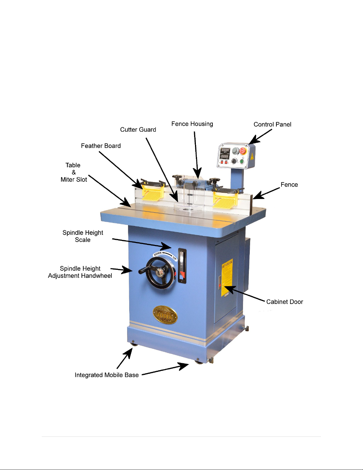
Identification
8 | Page Oliver Machinery 10047VS Shaper
Page 9
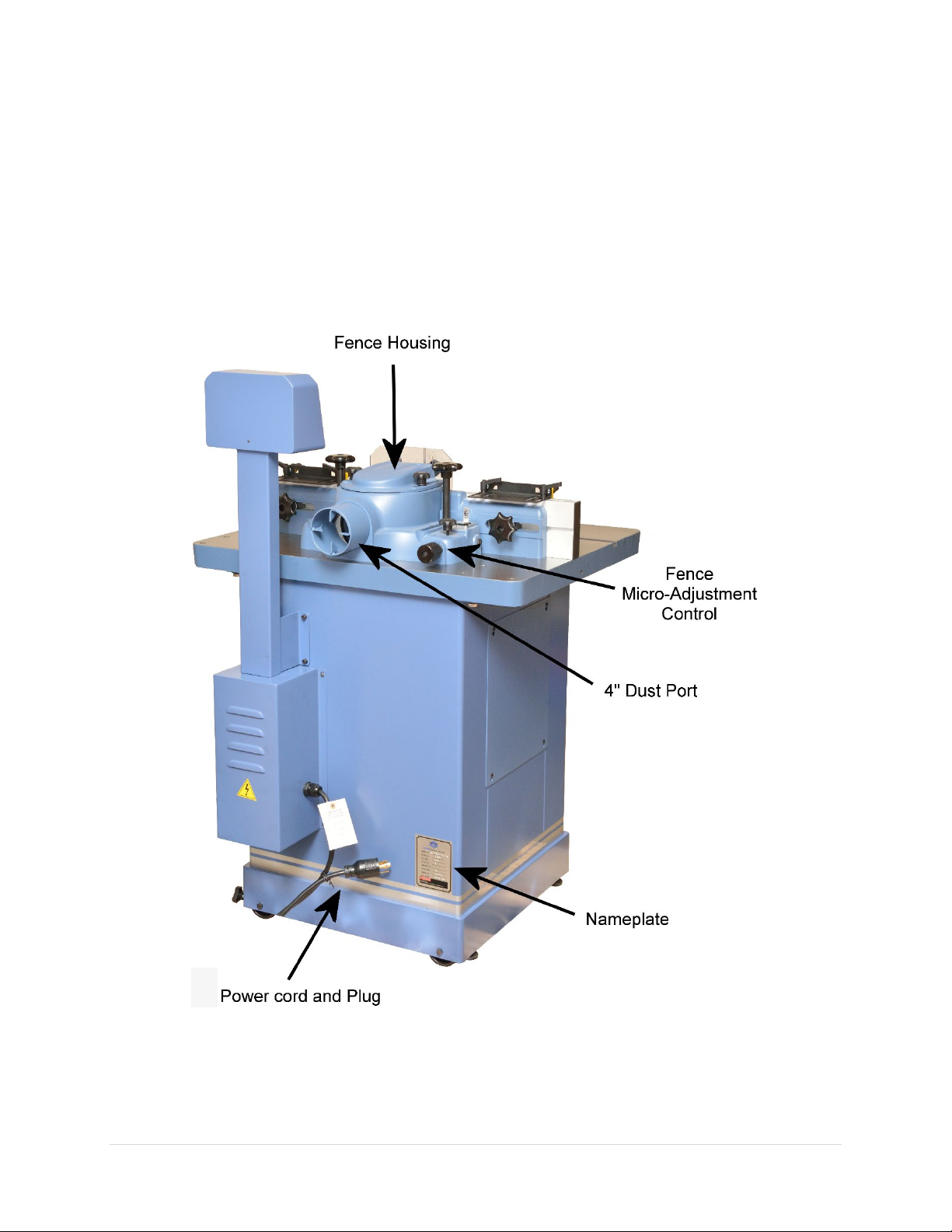
10047VS Shaper OLIVERMACHINERY.NET 9 | Page
Page 10
Safety
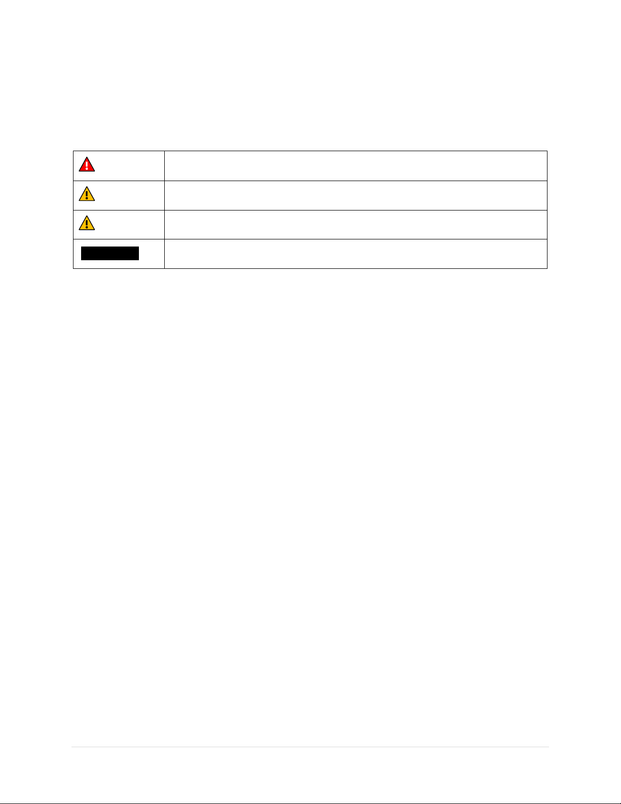
This indicate an imminent hazardous situation which, if not avoided, WILL cause
Oliver Machinery has made every attempt to provide a safe, reliable, easy-to-use piece of machinery.
Safety, however, is ultimately depending on the individual machine operator. Before operating this
machine, please become familiar with the following safety labels and guidelines.
DANGER
WARNING
CAUTION
IMPORTANT This is a tip about proper operation of the machine to avoid machine damage.
death or serious injury.
This means if the warning is not taken seriously, it CAN cause death or serious injury.
This means if the precaution is not taken, it MAY cause minor or moderate injury.
General Safety Guidelines
1. FAMILIARIZE yourself with all safety instructions found in this manual. Know the limitations and
hazards associated with this machine. Do not operate / service this machine until you are properly
trained.
2. ELECTRICAL GROUNDING, when done properly, reduce the risk of electrocution, shocks and fire.
Make certain that the machine frame is electrically grounded and that a ground lead is included in the
incoming electrical service. In cases where a cord and a plug are used, make certain that the grounding
plug connects to a suitable ground. Follow the grounding procedure indicated in the electrical code
of your area.
3. DISCONNECT the machine from power before performing any service, maintenance, adjustments or
when changing cutters. A machine under repair should be RED TAGGED to show it should not be used
until the maintenance is complete.
4. EYE PROTECTION: Always wear an approved safety face shield, goggles, or glasses that complies with
ANSI Z87.1 and CSA Z94.3 standards. Common eyeglasses are not safety glasses, and may not provide
adequate protection.
5. EAR PROTECTION: Use hearing protective devices where the noise exceeds the level of exposure
allowed in Section 1910.95 of the OSHA Regulations. When in doubt, use it.
6. OTHER PERSONAL PROTECTION: Before operation, remove tie, rings, watch and other jewelry. Roll
up sleeves above elbows. Remove all loose outer clothing and confine long hair. Protective type
footwear should be used. Do not wear gloves unless it is instructed to perform particular step(s) in
the manual.
7. GUARDS: Keep machine guards in place for all applicable operations. If any guards are removed for
maintenance, DO NOT OPERATE machine until all guards are reinstalled. Check clearance between
the guards and the cutter before starting the machine.
8. WORKPLACE SAFETY: Keep the floor around the machine clean. Scrap material, saw dust, oil and other
liquids increase the risk of tripping or slipping. Be sure to clean up the table before starting the
10 | Page Oliver Machinery 10047VS Shaper
Page 11

machine. Make certain work area is well lighted and that a proper exhaust system is used to minimize
dust. Use anti-skid floor strips on the floor area where the operator normally stands and mark off
machine work area. Provide adequate work space around the machine.
9. ACCESS CONTROL should be enforced so only trained personnel can access the work area and operate
the machine. Use childproof power switch when applicable.
10. STAY ALERT at all times. Do not operate this machine while under the influence of drugs/alcohol, or
when not feeling well.
11. NEVER STAND ON MACHINE. This prevents injuries from tipping related accidents and accidental
contacts to cutters.
12. REPLACEMENT PARTS: Use only genuine Oliver Machinery replacement parts and accessories
recommended for this machine. Generic parts made by other manufacturers may create a safety
hazard, and WILL void the factory warranty and other guarantees.
13. PROPER USE: Do not use this machine for other than its intended use. If used for other purposes,
Oliver Machinery disclaims any real or implied warranty and holds itself harmless for any injury or
damage which may result from that use.
10047VS Shaper OLIVERMACHINERY.NET 11 | Page
Page 12
Safety Guidelines Specific to Shaper
Before Work Begin:
1. INSPECT CUTTER: Make sure cutters are sharp, clean, balanced and free from damages. Forcing dull
cutters to work invites accidents and impacts finish quality.
2. CUTTER POSITIONING: Whenever possible, position the cutter below the workpiece and make blind
cuts with hold-downs. Doing so reduce operator’s exposure to the cutter.
3. SECURE SPINDLE AND CUTTER: Make sure the spindle and the draw bar are tightened on the arbor.
4. KEYED COLLAR: Never operate the shaper without the keyed collar located
immediately under the spindle washer. Key collar prevents the cutter from coming
loose when the spindle rotates. Do not substitute any other type of washer/spacer in
place of the keyed collar.
5. CUTTER CLEARANCE: Adjust fence plates and guard, and use correctly sized table inserts to create
practically minimal cutter clearance. Never start shaper with workpiece touching the cutter.
6. CHECK SPINDLE SPEED AND SPINDLE-FEED DIRECTION: Always start this shaper at the lowest speed,
and never set rotation speed above the rated RPM of the cutter. Always feed stock against cutter
rotation direction to maintain better control of stock.
7. CHECK STOCK LENGTH: Never shape stock less than 12 inches in length without special fixtures. When
practical, shape longer stock and cut to size.
8. SHAPE ONLY QUALITY WOOD: This machine is designed for wood products only. Do not shape any
material other than wood. Do not attempt to shape workpiece with loose knots or with any other
foreign material. Do not attempt to shape twisted, warped, bowed stock. Use a jointer to flatten stock
prior to shaping.
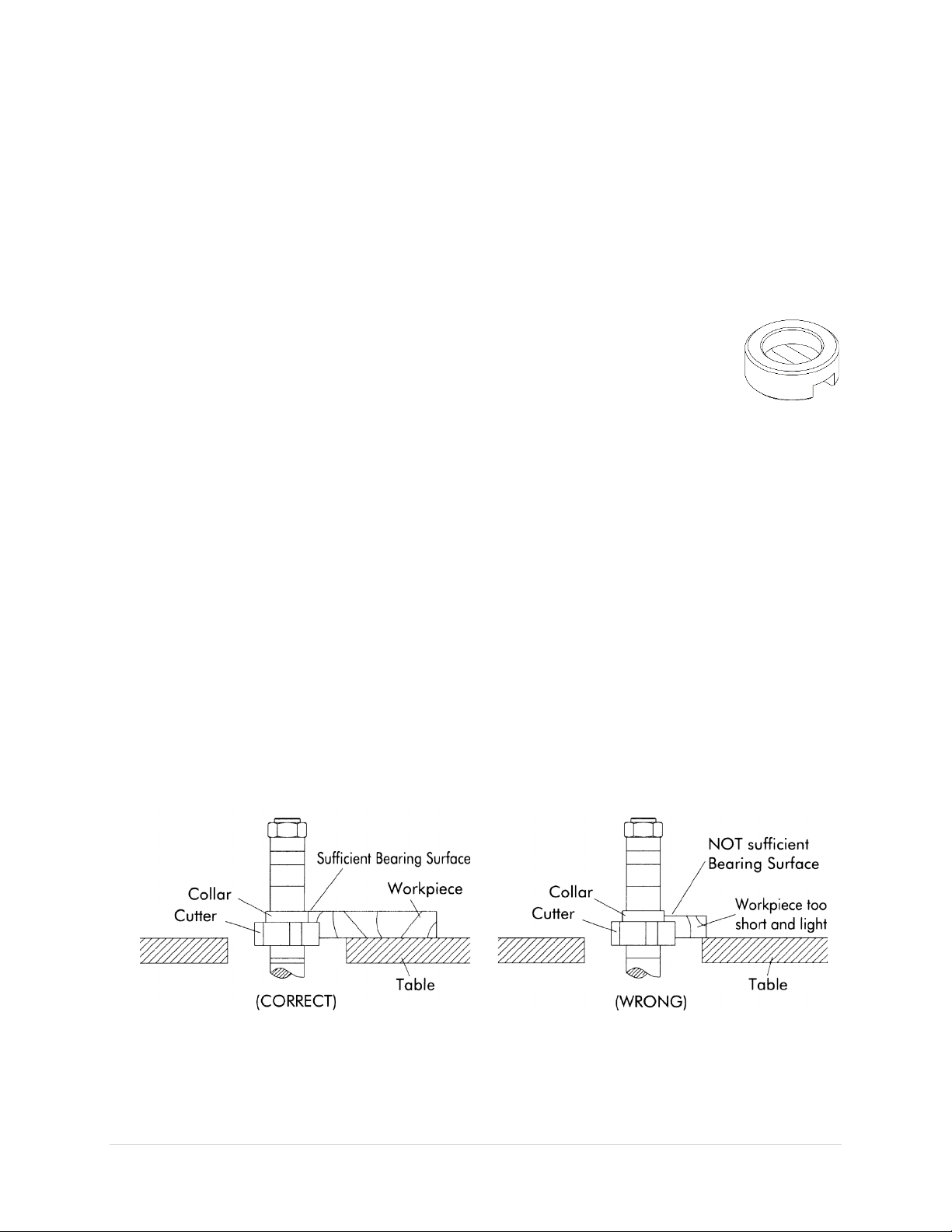
9. COLLARS: When shaping with collars, the collar must have sufficient bearing surface. The work must
also be fairly heavy in proportion to the cut being made. Do not use short, lightweight stock when
shaping against collars.
12 | Page Oliver Machinery 10047VS Shaper
Page 13
When Shaping:
When using miter gauge, do not feed
workpiece can bind and kickback may
occur.
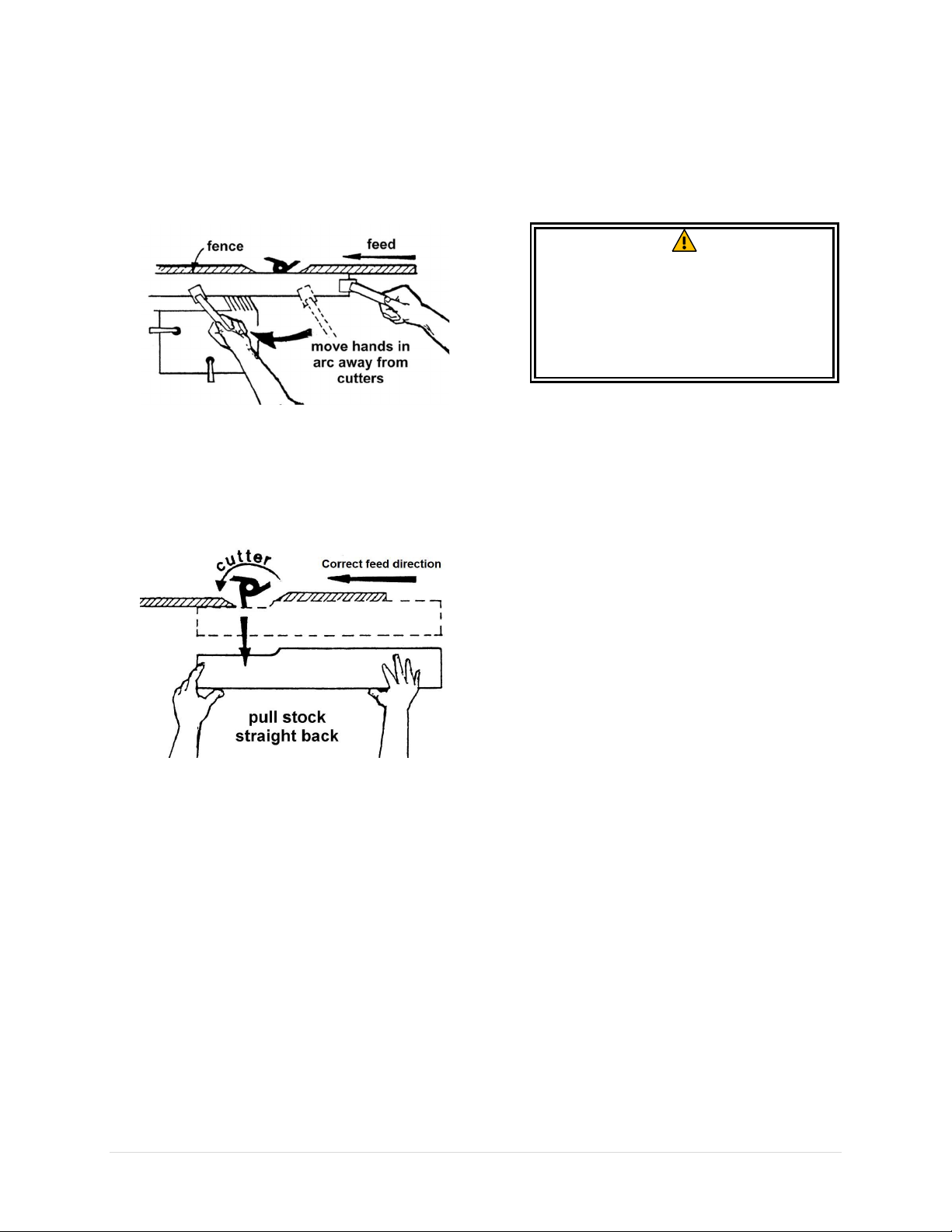
1. 6-INCH RULE: To avoid accidental cutter
contact, never allow your hands to come
closer than 6 inches to the cutters. Use push
block, jigs, and hold-downs to safely feed the
workpiece while cutting.
2. NO CLIMB CUT: To prevent kickback, feed
stock opposite to the direction of the cutter
rotation. Never back stock out of the cutter
once the cut has been started. Instead, pull
the stock straight back away from cutter and
begin the cut again.
3. SHAPING SHORT EDGE: When shaping
workpiece with an edge shorter than 6”, use
miter gauge and hold down fixtures for
feeding.
WARNING
workpiece against the fence. If the fence
is not perfectly parallel to the miter slot,
4. FREEHAND SHAPING is for advanced users
only. Always use a starting pin or pivot board
when starting a cut. Never start shaping at a
corner.
5. MAKE LIGHT PASSES: Never force the cutter
to remove too much material in one pass.
Doing so increase the risk of kickback and
impact finish quality. Make several light
passes when applicable.
6. KEEP HANDS SAFE: Do not clear dust and
debris with hands; use a brush or
compressed air instead.
After Operation
1. STOP THE MACHINE when operator leaves the machine for any reason.
2. WAIT until the cutter comes to a complete stop.
3. CLEAN UP before departure.
10047VS Shaper OLIVERMACHINERY.NET 13 | Page
Page 14

Electricals
Stock Number
Minimum Circuit Size Required
10047VS.001
30A
Amps
Power Cord Length
25 feet
50 feet
75 feet
100 feet
8 to 12
14
14
12
10
12 to 15
12
12
10
10
15 to 20
10
10
10
NR
21 to 30
10
NR
NR
NR
Use properly sized wires that meet or exceed the power requirement of your
and machine damage.
All electrical work must be done by a qualified electrician, and must meet the
WARNING
Minimum Circuit Size Required for Model 10047VS Shaper
Please ensure the electrical circuit for this machine meets the minimum circuit size requirement.
Minimum circuit size requirement applies to a dedicated circuit which provides power to one
Shaper. If more machines are sharing the same circuit, consult a qualified electrician to ensure the
designated circuit is properly sized for safe operation.
If a circuit is available, but not meeting the minimum circuit size requirement listed above, a new circuit
must be installed for this machine.
Grounding
electrical code in your area.
10047VS
WARNING
Proper grounding reduces the risk to the operator in the event of electrical malfunction or breakdown.
This machine must be connected to the grounding conductor when available, and all grounding
connections must meet or exceed the electrical code requirements in your area. Furthermore, all grounds
must be verified and must meet or exceed the electrical requirement of the machine. If grounding is not
available, consider the use of a GFCI protection device as an alternative, if this complies with the electric
code in your area.
Improper grounding can cause electric shock, fire, and equipment damage.
Electrical Wiring
This machine is pre-wired for 230V with a cord and a NEMA L6-30 plug. Use of extension cord is not
recommended. If you need to use an extension cord to connect to a power source, select a durable cord
type with high temperature rating (90C° or above). Use minimum amount of extension cord as needed.
Minimum cord size (AWG) required based on amperage draw and length of the cord:
*NR: Not Recommended
WARNING
14 | Page Oliver Machinery 10047VS Shaper
machine. Using undersized wires may cause overheating and increase the risk of fire
Page 15
Setup
Air resistance and leakage in a dust collection
Use
a dust collection system that is rated above
. Doing so
improves air quality in the workplace, and
Shop Preparation
Space Requirement
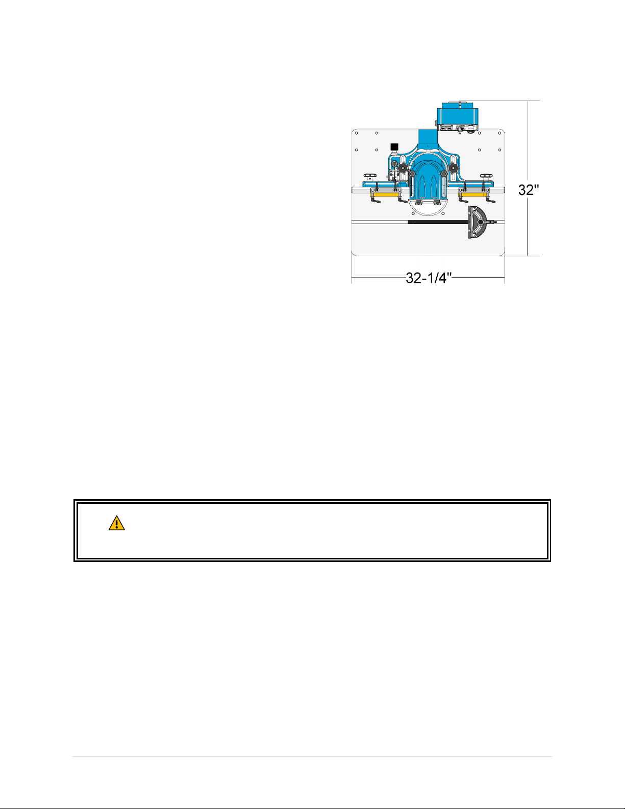
The dimensions of this machine are 32-1/4“(L) x 32”(W).
You will need additional spaces for manipulating your
workpiece, electrical connection and dust collection.
Load Limits
This machine has a shipping weight of 511 lbs., and a net
weight of 396 lbs. Please ensure all lifting tools and building
structures have adequate load capacity, for transporting
and supporting the total weight of this machine, the
operator, and related items.
Electricals
Make sure properly sized circuit and electrical outlet are available near the machine. Please refer to
section “Electricals” on page 14 for details regarding electrical requirements.
Lighting
Adequate lighting is needed for operating this machine. Overhead, non-glare lighting should be installed.
Safety Labels
If this machine introduces a new safety hazard to your work place. Please display proper warning signs in
highly visible location(s).
Dust Collection
Wood dust created by this shaper is a health hazard. Connect this machine to a dust collection system.
Check the air suction regularly to ensure dust and shavings are effectively removed.
Dust masks should be available for using the shaper.
system impacts its effectiveness.
800 CFM at dust port
prevents machine from jamming.
CAUTION
10047VS Shaper OLIVERMACHINERY.NET 15 | Page
Page 16
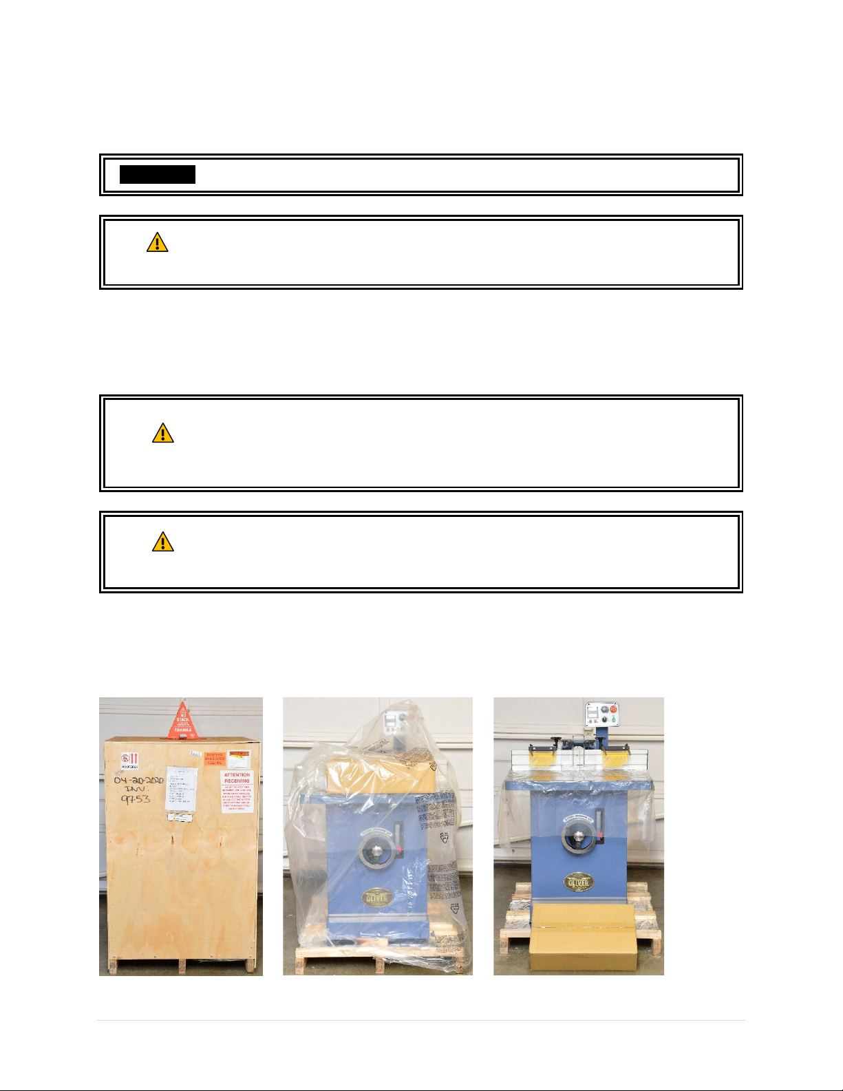
Receiving
Your shipment should come with one wood crate with pallet base. Upon receiving your shipment, check
for any significant damages before signing the delivery confirmation.
IMPORTANT
CAUTION
Moving Machine into the Shop
Your machine will be delivered by freight service, and it will be left outside of your workshop by default.
On the day of delivery, please be sure help is available to move the machine to its final location.
WARNING
WARNING
You may need to remove strapping that is used for securing your package.
Strapping may spring back violently when released and cause injury. Always wear
safety goggles and gloves for this task.
10047VS Shaper has a gross weight of 511 lbs. and a net weight of 396 lbs.
Safe moving techniques and proper lifting equipment required, or serious personal
injury may occur.
Your machine may be secured by the straps. Do not lift your shipment by the
strap. They are not designed to hold the total weight of your shipment. They may
snap without warning and cause serious injury and machine damage.
If items are damaged, please call us immediately at 1-800-559-5065
Unboxing
Upon removing the crate cover, you should find a shaper that is mostly assembled, and a paper box that
contains all loose parts and accessories.
16 | Page Oliver Machinery 10047VS Shaper
Page 17
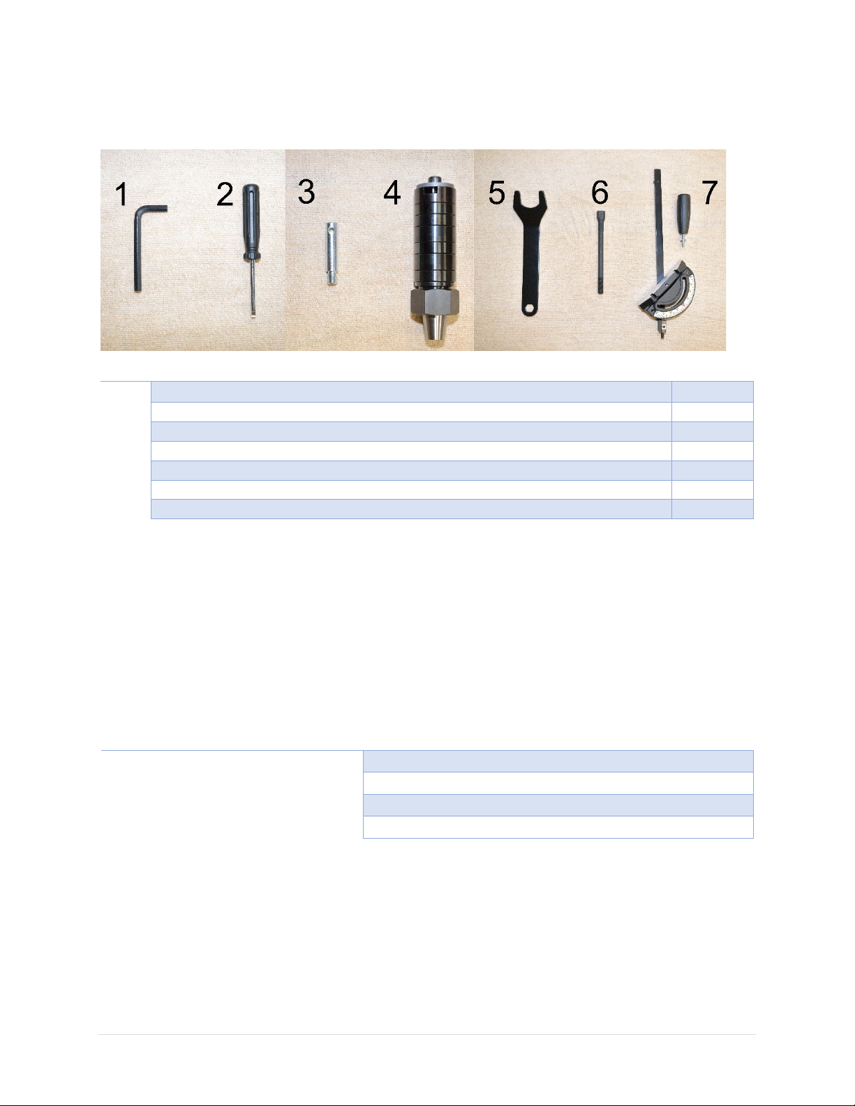
Inventory
Item
Description
Quantity
1
8mm Hex Key
1
2
Screw driver
1
3
Starting Pin
1
4
1-1/4” Spindle Assembly
1
5
Wrench for spindle nut and spindle draw bar
1
6
Spindle draw bar
1
7
Miter gauge assembly
1
Item
Purpose
Safety glasses
Protection
Disposable gloves
Protection
Paper Towel
Cleaning
Rust Inhibitor
Cast iron table top rust protection.
Carefully unwrap the packaging and make sure all components are included in the shipment. Lay out all
items received and inventory them.
NOTICE: If you cannot find an item in the list above, please check if it is still attached to the packaging or
inside the cabinet. Occasionally the item may have been pre-installed in factory. See section “Parts List”
to check if a component is included or installed.
NOTICE: This machine comes with various standard sized, non-proprietary parts. If any of these parts are
missing, we be happy to deliver them to you. To have the machine up and running as soon as possible,
you can also find these parts at your local hardware store.
Additional Items Needed for Machine Assembly
When all items are ready for setting up the machine, gently remove the machine from the pallet. Lift the
shaper with its table. If using a forklift or any metal lifting devices, ensure the table is protected by
paddings. Gently lower shaper on the floor to prevent damages to the casters.
10047VS Shaper OLIVERMACHINERY.NET 17 | Page
Page 18
Cleaning
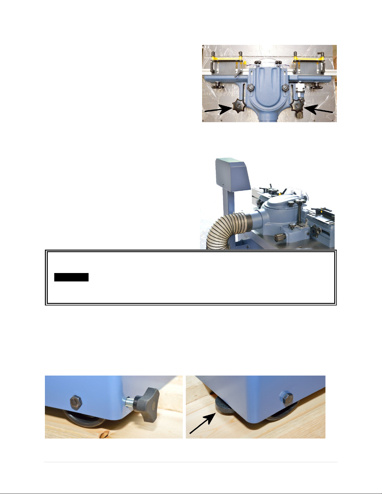
To prevent rusting, the cast iron tabletop of this shaper
is covered with rust protectant and plastic film.
Remove both fence assembly lock knob to remove the
fence assembly. Then pull out the plastic film and wipe
off rust protectant with paper towels.
Once all rust protectant is removed, routinely coat the
table top with rust preventive such as Boeshield® T-9
or paste wax. Do not use rust preventives that contains
silicon, which is known to interfere with certain
finishes and glues.
Dust Collection
Shaper can generate a lot of wood shavings and dust.
Connect this machine to a dust collection system.
Minimum CFM requirement for this shaper is 800 CFM
at the dust port, which means your dust collection
system should have a rating greater than 800 CFM, as
air friction and leakage reduce effective CFM at the
dust port.
Running this shaper without dust collection system, or using a dust collection
system with inadequate suction, will cause dust and shavings to accumulate
IMPORTANT
inside the cabinet. This can damage the machine and cause other hazardous
situations. Check your dust collection system regularly to make sure it is not
jammed or filled up.
Moving / Leveling Machine
This shaper is equipped with casters so it can be moved easily. To keep the shaper in place, tighten the
caster locking knobs and lower the rubber feet.
If shaper is standing on uneven floors, use rubber feet to level the machine.
18 | Page Oliver Machinery 10047VS Shaper
Page 19
Controls and Operation
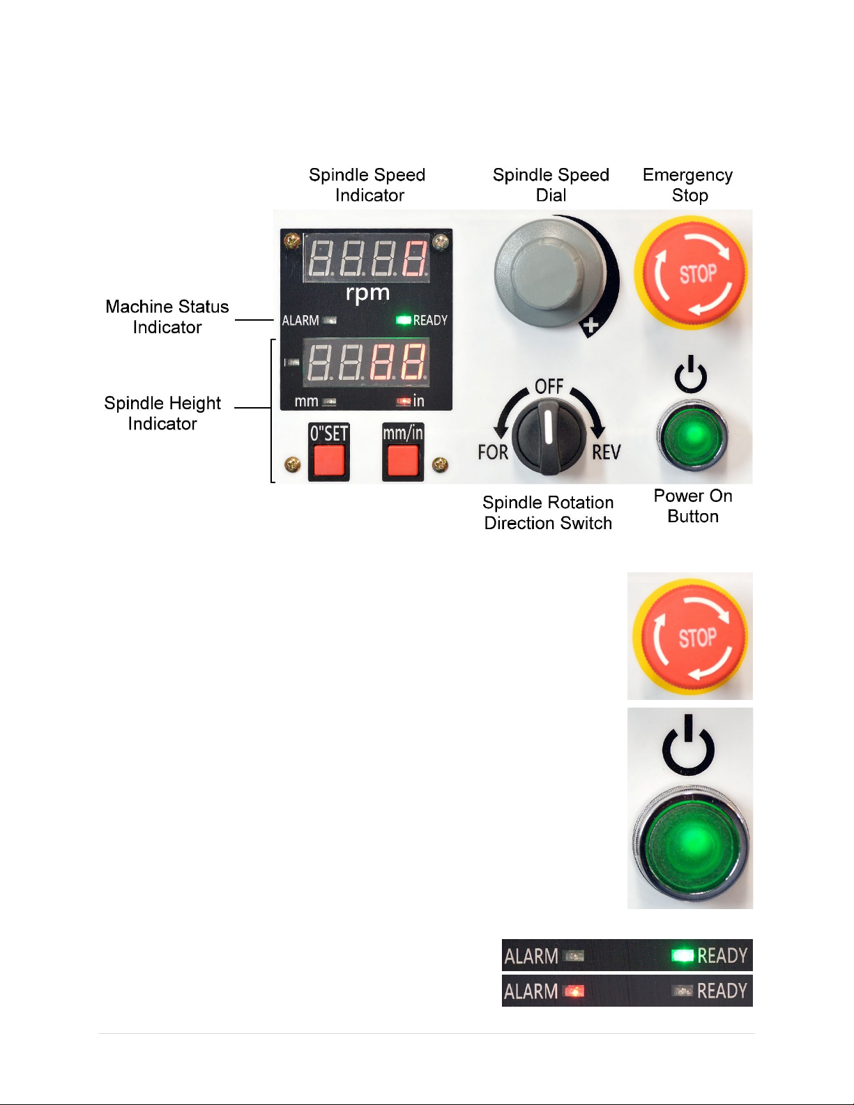
Control Panel Overview
Emergency Stop
Emergency stop button stops the machine and prevents unintentional restarts.
Once pressed, the shaper will stop, and the emergency stop button will have to be
reset before the shaper can be restarted. To reset, rotate the button clockwise until
it pops up.
Magnetic Power Switch
Press this button to power on the shaper so it is ready to run.
NOTICE: This magnetic switch will automatically shut off upon power outage. This
prevents unintentional restarts when power resumes.
To restart the machine after a power outage, set spindle direction switch to OFF
position, and set spindle speed to minimum, then press the power button to power
on the machine.
Machine Status Indicator
Indicates if the motor is ready to run. If the “ALARM” light is
on, motor will not start. Hit STOP button and wait for 1 minute
for the machine to reset.
10047VS Shaper OLIVERMACHINERY.NET 19 | Page
Page 20
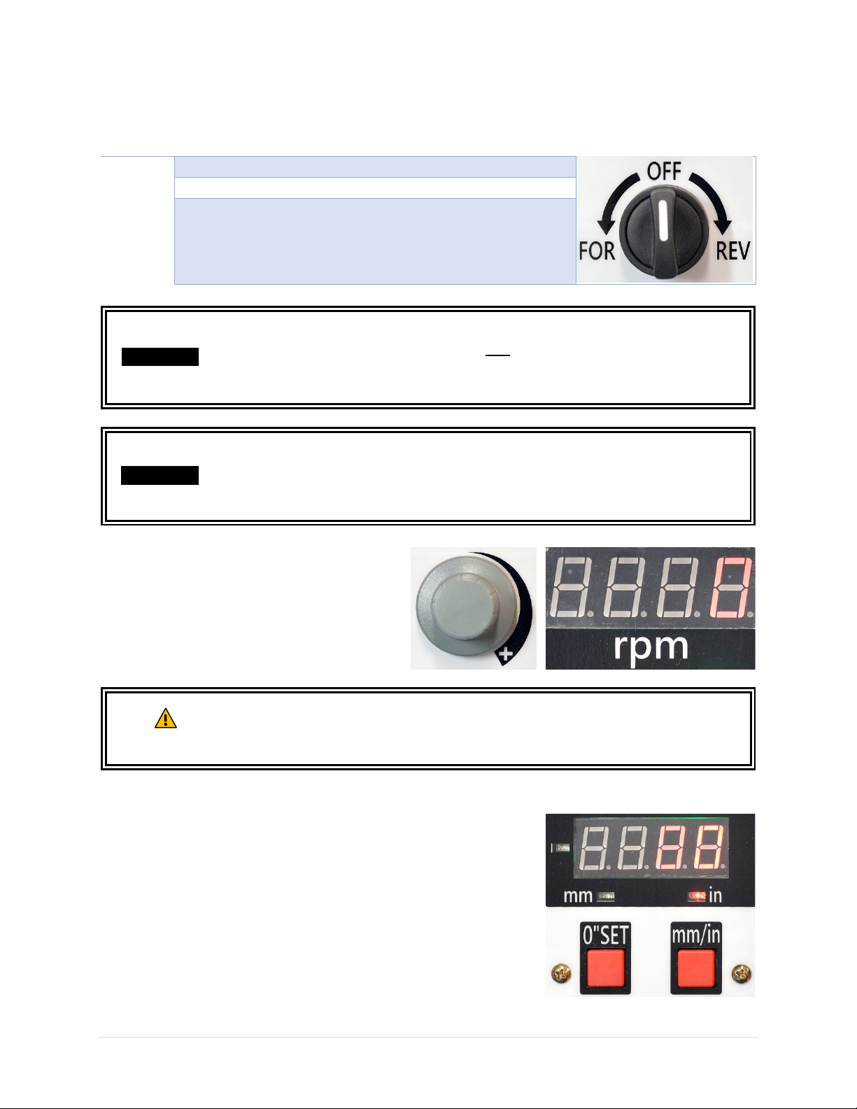
Rotation Direction Switch
Position
Spindle Rotation Direction
“FOR”
Counter-clockwise
“REV”
Clockwise
“OFF”
Spindle does not rotate
This switch allows operator to set spindle rotation direction after the machine is powered on.
This machine comes with a safety feature which prevents unintentional startup.
IMPORTANT
IMPORTANT
The rotation direction switch must be at OFF position before machine is powered
on, otherwise the alarm light will turn on and machine will have to be reset
before it can start again.
Only change spindle rotation direction after the spindle has come to a complete
stop, or machine damage may occur.
Always turn this switch to OFF position when operation completes.
Spindle Speed Dial & Indicator
Controls spindle speed between 5000 and
10000 RPM. Real time spindle RPM is displayed
on spindle speed indicator.
Always start this shaper at the lowest RPM and then increase to a safe speed for
WARNING
operation. NEVER set RPM above the cutter’s rated speed or cutter may
disintegrate. Serious body injury and machine damage may occur.
Spindle Height Indicator
This digital readout shows current position of the spindle relative to a
reference point set by the user. When spindle moves above the
reference point, the Indicator will show a positive value, and vice
versa.
To Set a Reference Point:
Press [0” SET]
To Change Measurement Unit:
Press [mm/in.]
20 | Page Oliver Machinery 10047VS Shaper
Page 21
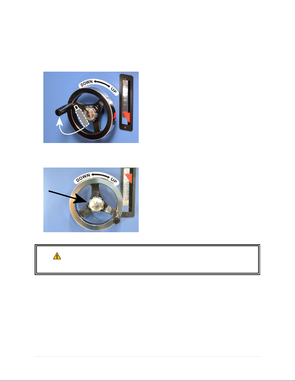
Spindle Height Adjustment
The spindle height adjustment handwheel is located in front of the shaper cabinet.
1. To adjust spindle height, flip wheel handle
up.
2. Loosen locking knob if the height adjustment
handwheel is locked.
3. Turn handwheel clockwise to move spindle
up, and vice versa.
4. Operator can use both digital readout and
spindle height scale to measure the
elevation of spindle.
5. To lock the spindle height, tighten the
locking knob.
6. The wheel handle can be folded when all
adjustments are done.
After adjusting spindle height, always verify clearance between the cutter and the
WARNING
10047VS Shaper OLIVERMACHINERY.NET 21 | Page
guard/table insert/fence before starting the machine. Serious injury and machine
damage may occur if cutter strikes any stationary part of the shaper.
Page 22
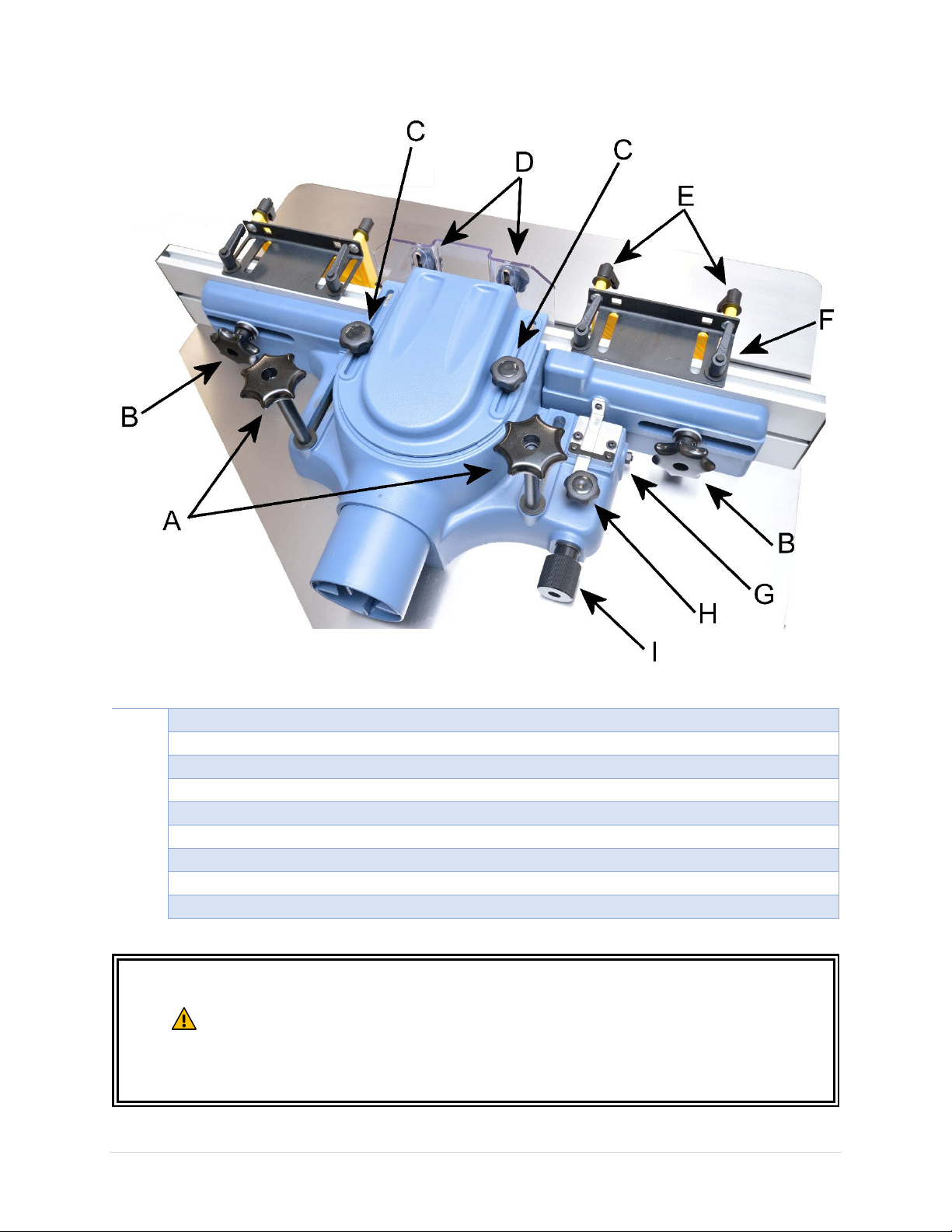
Fence Assembly
Key
Component
A
Fence housing lock knob
B
Fence plate lock knob
C
Cutter guard lock knob (horizontal)
D
Cutter guard lock knob (vertical)
E
Featherboard lock
F
Featherboard bracket lock
G
Vernier scale
H
Micro adjustment lock
I
Micro adjustment dial
WARNING
Always turn off machine and wait for the spindle to come to a complete stop
before adjusting the fence.
Always re-lock all adjustable components of fence assembly and verify cutter
clearance after adjusting the fence. Without enough clearance, cutter will strike
the fence which may result in serious body injury and machine damage.
22 | Page Oliver Machinery 10047VS Shaper
Page 23
Fence Adjustments
Reposition aluminum fence plate:
Measure fence position using Vernier scale:
1. Loosen the fence plate lock knob [B].
2. Adjust fence plate position based on the
size of the cutter installed. Make sure
there is enough clearance for cutter to
rotate freely.
3. After setting the position of the fence
plate and verified cutter clearance, retighten the fence plate lock knob.
Adjust infeed fence positions:
1. Loosen fence housing lock knobs [A].
2. Move the entire fence assembly to adjust
the infeed fence position relative to the
cutter.
3. Check cutter clearance, then re-tighten
fence housing lock knobs when adjustments
complete.
Adjust cutter guard clearance:
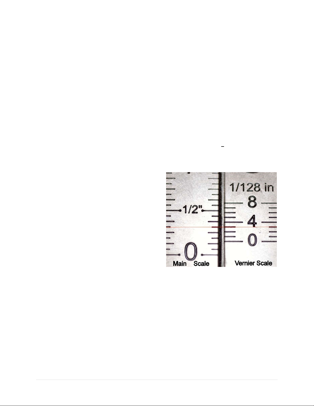
1. Read the main scale where it is passed by
the Vernier scale’s zero. That is the main
scale reading.
2. Find the first mark on the Vernier scale
that lines up perfectly with any line on the
main scale. Multiply the number of that
mark by 1/128”. That is the Vernier scale
reading.
3. The exact position is the sum of the main
scale and Vernier scale readings.
Example:
This picture shows the 3rd mark on the Vernier
scale lines up with a line on the main scale, while
the zeroth mark passed the 1/8” mark on the
main scale:
1. Loosen horizontal guard lock knobs [C] and
vertical guard lock knobs [D] to adjust cutter
guard position.
2. After setting guard position and verified
cutter clearance, re-tighten the lock knobs.
Micro-adjust outfeed fence positions:
1. Loosen the outfeed fence micro adjustment
lock [H].
2. Rotate the micro-adjustment dial [I] to move
the outfeed fence forward or backward. One
revolution of the dial moves the fence by
approximately 5/64”. The outfeed fence can
move forward by at most 7/8”.
3. The Vernier scale [G] indicates the position
of outfeed fence relative to the infeed fence,
with precision of 1/128”.
4. After setting the position of the fence and
verified cutter clearance. Re-tighten micro
adjustment lock.
Main Scale Reading: 1/8”
Vernier Scale Reading: 3 * 1/128 = 3/128”
Exact position:
1/8” + 3/128” = 19/128”
10047VS Shaper OLIVERMACHINERY.NET 23 | Page
Page 24
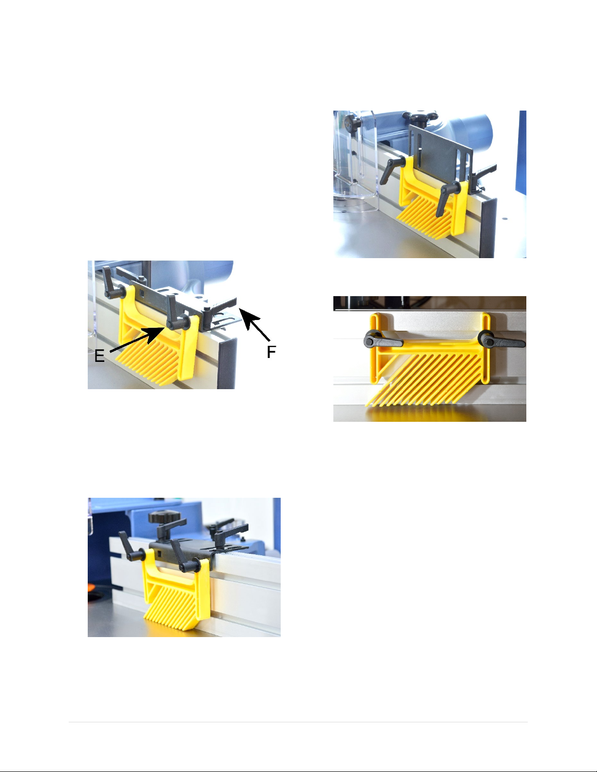
Reposition featherboard:
Whenever possible, use featherboards to hold
the workpiece down for shaping. This reduces
the risk of kickback and keeps hands away from
the cutter.
This shaper comes with two featherboards and
mounting brackets, which allows various ways of
setting up the featherboard.
1. Featherboard can be mounted on any
position along the fence. Loosen the
featherboard bracket locks [F] to adjust
featherboard position, and retighten them
when done.
4. To hold down thick/tall stock, the
mounting bracket can be flipped 90° and
featherboard can be mounted as shown in
the picture:
5. The featherboard can also be directly
mounted on the aluminum fence if desired.
2. The height of the featherboard can be
adjusted by loosening the featherboard
locks [E].
3. If the featherboard needs to be lowered
even further, flipped over the mounting
bracket and mount the featherboard as
shown in the picture.
6. Additional featherboards (purchased
separately) can be mounted on shaper
table’s miter slot to ensure stock is pushed
firmly against the fence.
24 | Page Oliver Machinery 10047VS Shaper
Page 25
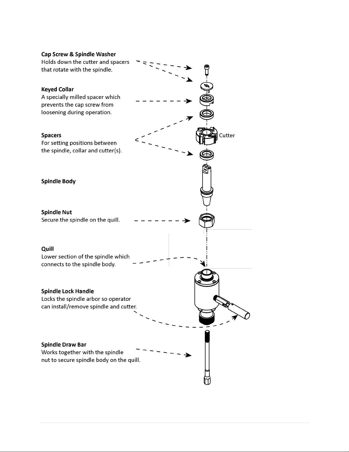
Spindle Assembly Components and Functionalities
10047VS Shaper OLIVERMACHINERY.NET 25 | Page
Page 26
Spindle / Cutter Setup
Before changing spindle, cutters or collets, disconnect machine from power source
WARNING
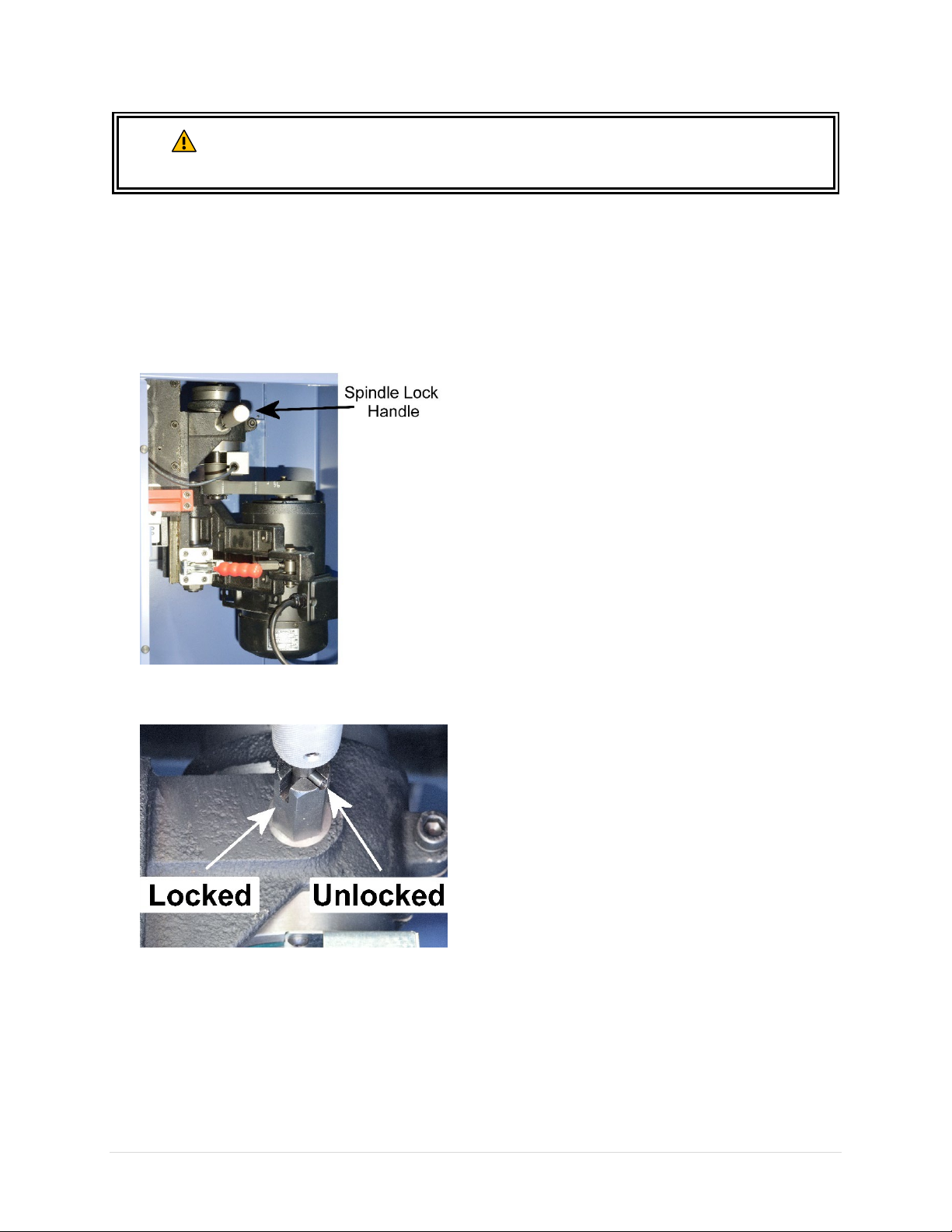
Lock / Unlock Spindle Arbor
To Lock Spindle Arbor
and lock spindle arbor. Failure to comply may result in serious injury.
To Unlock Spindle Arbor
1. Disconnect machine from power source!!
2. Open cabinet door and locate the spindle
lock handle.
3. Pull and rotate the handle until the pins
engage into the “Locked” position.
1. Disconnect machine from power source!!
2. Pull and rotate the handle until the pins
engage into the “Unlocked” position.
3. Rotate spindle / pulley by hand to ensure
the lock is disengaged.
4. Close cabinet door before starting the
shaper.
4. Rotate spindle / pulley by hand until the
spindle lock engages.
26 | Page Oliver Machinery 10047VS Shaper
Page 27
Install / Remove Spindle
WARNING
Disconnect machine from power source before installing/removing spindles.
Failure to comply may result in serious injury!
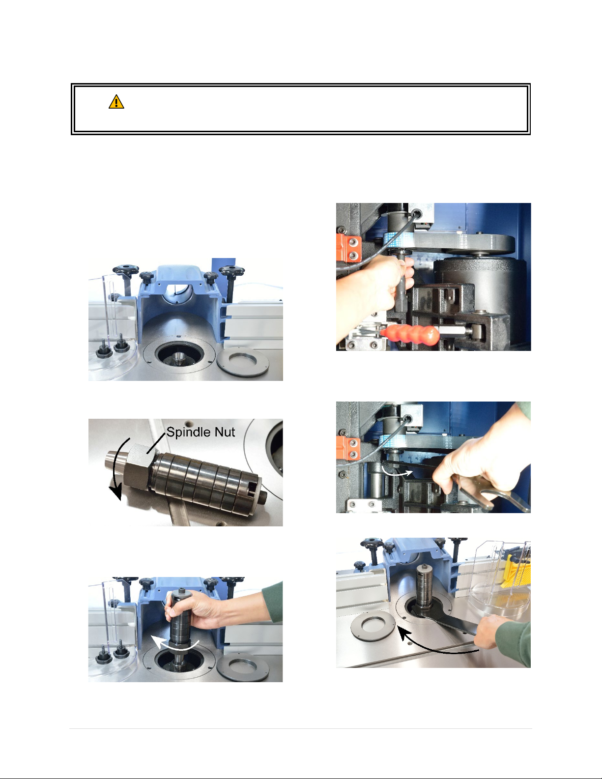
To Install Spindle:
1. Disconnect machine from power source!!
2. Lock spindle arbor.
3. Move cutter guard and fence away from the
table opening. Remove table inserts to gain
access of the quill.
4. Hand thread spindle nut all the way into the
spindle.
6. Insert spindle draw bar up into the hole at
the bottom of the spindle pulley.
7. Thread and tighten the draw bar with the
spindle wrench provided. You may also find
a ratcheting wrench useful in tight space.
5. Raise arbor all the way up, then lower the
spindle straight into the quill. Hand thread
the entire spindle assembly into the quill.
IMPORTANT: Take extra care not to cross
thread, or the spindle/quill connection will
be damaged.
10047VS Shaper OLIVERMACHINERY.NET 27 | Page
8. Tighten the spindle nut with spindle wrench.
Page 28

9. If you need to install cutters, continue with
section “Installing/Removing Cutters” for
details.
10. Otherwise, unlock the spindle arbor.
11. Close the cabinet door.
12. Reconnect machine to power source when
all adjustments complete.
To Remove Spindle
• Disconnect machine from power source!!
• Lock the spindle arbor.
• Loosen and remove the draw bar.
• Use the spindle wrench to loosen the spindle
nut, then continue to rotate the spindle nut
until it breaks free of the quill.
28 | Page Oliver Machinery 10047VS Shaper
Page 29
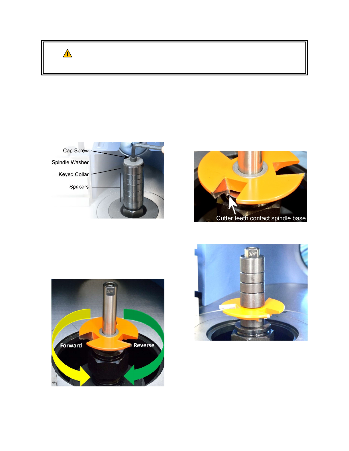
Install Shaper Cutter
When changing cutters, disconnect the machine from its power source. Wear thick
WARNING
To Install Cutter
leathers gloves to prevent hand injuries. Do not use damaged cutters, as it may
disintegrate during operation and cause serious injuries.
1. Disconnect machine from power source!!
2. Lock spindle arbor.
3. Remove cap screw, spindle washer, keyed
collar, and extra spacers from the spindle,
then install shaper cutter.
4. IMPORTANT: Pay attention to the
orientation of the cutter blade. When
rotation switch is set to “FOR” (Forward), the
spindle will rotate counter-clockwise, and
vice versa. Operator should set up the
spindle assembly such that cutter rotation
direction goes against feed direction.
5. IMPORTANT: It is generally advisable to
place the cutter as low as possible on the
spindle to reduce spindle deflection. This
setup creates the best possible finish.
However, if cutter blades contact the base of
the spindle body, the cutter will need to be
raised with spacers.
6. After the cutter is properly inserted, Add
more spacers on top of the cutter.
10047VS Shaper OLIVERMACHINERY.NET 29 | Page
Page 30
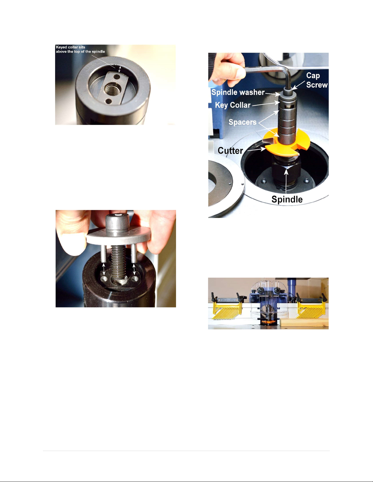
7. Then insert the keyed collar.
IMPORTANT: The keyed collar MUST sit
slightly ABOVE the top of the spindle. This
ensures significant pressure is applied to
hold down the cutter during operation.
8. Install spindle washer and the cap screw.
NOTICE: Spindle washer may or may not be
pronged. If a spindle is equipped with a
pronged washer, make sure the prongs are
inserted into the holes of the spindle.
9. Thread and tighten the cap screw with an
8mm hex wrench.
10. After cutter is securely installed, unlock the
spindle arbor.
11. Rotate the spindle to ensure cutter rotates
freely. Adjust fence, guard and use the right
table insert to create practically minimal
cutter clearance.
30 | Page Oliver Machinery 10047VS Shaper
Page 31
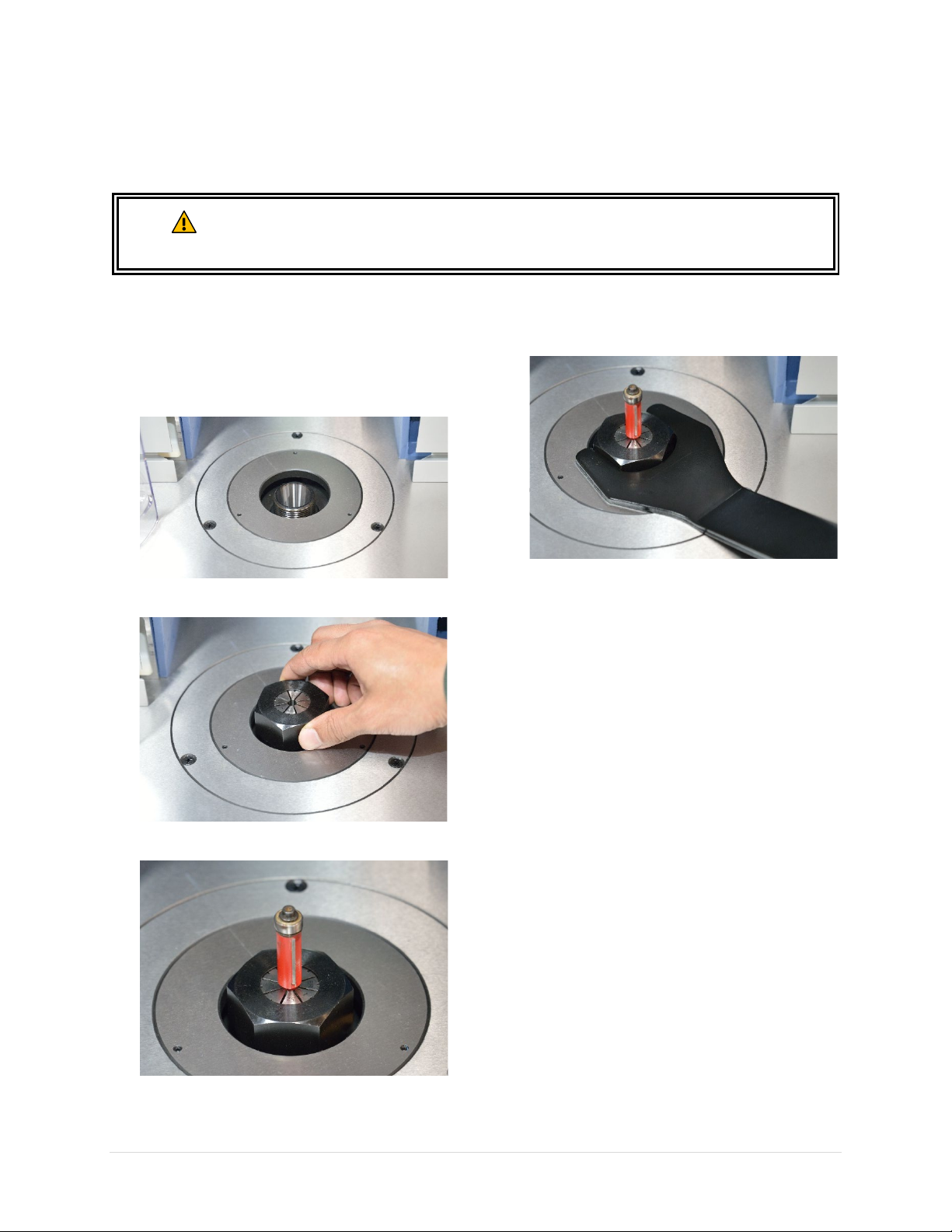
Installing/Removing Router Collets (Sold Separately)
Two optional router collets (1/4” & 1/2”) are available for this shaper. To purchase these collets, please
visit our website or call our parts department at 1-800-559-5065.
Disconnect machine from the power source before installing/removing collets.
WARNING
To Install Router Collet
Failure to comply may result in serious injury!
1. Disconnect machine from power source!!
2. Lock spindle arbor.
3. Raise spindle arbor all the way up.
4. Hand thread the router collet onto the arbor.
6. Tighten the collet with spindle wrench.
7. When collet is secured, unlock the spindle
arbor.
8. Rotate the collet to ensure cutter rotates
freely. Adjust fence, guard and use the right
table insert to create practically minimal
cutter clearance.
5. Insert the router bit into the collet.
10047VS Shaper OLIVERMACHINERY.NET 31 | Page
To Remove Router Collet
1. Disconnect machine from power source!!
2. Lock spindle arbor.
3. Raise the arbor all the way up.
4. Loosen the collet with the spindle wrench
provided.
Page 32

Test Run
Each shaper has been inspected and calibrated before leaving the factory to meet our quality and
precision standards. To get familiar with all safety features and controls before using this machine for
production work, it is advised to complete the following test run. Please remove spindle, cutters and clean
up shaper table before running the following tests.
☐ Verify emergency stop button prevents unintentional startups.
1. Press STOP button.
2. Connect shaper to power source.
3. Press the green power button.
4. STOP button is not reset. Machine will not power on.
☐ Verify rotation direction switch has to be at OFF position when machine is powered on, and machine
can be reset.
5. Reset STOP button by rotating it clockwise until it pops up.
6. Set rotation direction switch to “FOR” position.
7. Press the green power button. The red ALARM light should turn on, and motor should not start.
8. Press STOP button or unplug shaper. Wait for 1 minute for the machine to reset.
9. Set rotation direction to “OFF”.
10. Reset STOP button and press the green power button, the green READY light should turn on. Set
rotation speed to the lowest, then rotation direction to “FOR”, and motor will start.
☐ Verify magnetic switch is functional for preventing unintentional restart after a power outage.
11. Continue from previous step, with motor running, unplug machine from power.
12. Reconnect machine to power source. Motor should not restart.
13. After setting rotation direction switch to “OFF”, press the green power button to turn on machine,
and “READY” light will come on.
☐ Verify rotation switch and speed dial are functional.
14. Continue from previous step, set rotation direction to “FOR”
15. The quill should rotate counterclockwise when looking down through the table opening.
16. Set rotation direction to “OFF”
17. Wait until the quill comes to a complete stop, then set rotation direction to “REV”
18. The quill should rotate clockwise when looking down through the table opening.
19. Change rotation speed from minimum to maximum. RPM display should show machine speed
goes from 5000 RPM to 9999 RPM. Reduce speed to minimum when finished.
20. Set rotation direction to “OFF” to stop the motor.
☐ Verify spindle elevator and digital readout are functional.
21. Move spindle to the lowest position.
22. Readings of digital readout should change when lowering the spindle, and spindle can be lowered
to 0” as indicated on the spindle height scale.
23. Reset digital readout and raise spindle all the way up.
24. Spindle should be able to raise to 4” as shown on the scale and digital readout.
25. Press STOP button to power off machine and complete the test.
Congratulations for completing the test run! If you discover any issue from the tests, please refer to the
troubleshooting section and maintenance section to diagnose issues and make adjustments.
32 | Page Oliver Machinery 10047VS Shaper
Page 33
Preparation for Wood Shaping
Follow the “6-Inch Rule”. Keep your hands at least 6 inches away from the cutter
Use special jigs to hold down workpiece less than 12 inches long.
Material Selection and Inspection
Only use natural wood materials that is in good quality. Cracked stock, board with loose knots can break
apart and cause severe kickbacks, which can lead to severe injuries and machine damages.
Do not shape treated lumber or anything that contains harmful chemicals, as this will spread wood dust
that contain such harmful chemicals.
Carefully inspect workpiece for foreign objects. Nails, staples, rock chips and other objects embedded on
wood surface will damage shaper cutter. Clean workpiece with a stiff brush as needed.
Warped Stock
Workpiece should have at least one flat surface so it can be pushed firmly against the fence or the table
for feeding. Boards that are cupped, bowed or twisted should have at least one surface jointed flat before
being processed by a shaper.
Support Long Workpiece
Support long/wide boards with rollers or other devices to avoid injuries.
Safety Devices
To reduce the chance of kickback and accidental cutter contact, create special jig to hold down workpiece
that is less than 12” long, or if it is difficult to feed steadily. Use starting pin or pivot board to initiate a cut
for freehand shaping.
Shaping Wood
by using hold downs, push sticks, and/or push blocks.
WARNING
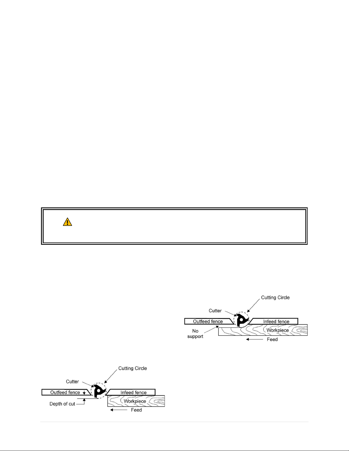
Shaping Long and Straight Pieces
Using the fence is the safest and the best way of
shaping straight pieces. Always use the fence
whenever the work permits. Depends on
situation, the infeed and outfeed fences will
need to be adjusted to properly support a
workpiece.
Case 1: Edge is partially shaped
When shaping a piece where a portion of the
original edge remains intact, both the infeed and
outfeed fences should be in line.
Case 2: Entire edge is shaped
When using the shaper for jointing work or
making a full bead, the shaped edge will not be
supported by the outfeed fence when both
fences are in line:
In this case, the outfeed fence should be adjusted
to support the workpiece. With the shaper
running, move a small section of the workpiece
through the cutter.
When the workpiece entered approximately 1/3
of the outfeed fence, stop the machine. Hold the
workpiece in place, and use the micro-
10047VS Shaper OLIVERMACHINERY.NET 33 | Page
Page 34
adjustment dial to move the outfeed fence
When using miter gauge, do not feed
inst the fence. If the fence is
not perfectly parallel to the miter slot,
workpiece can bind and kickback may occur.
forward, until it makes contact with the
workpiece. The outfeed fence will then be in line
with the cutting circle and supporting the
workpiece. Disengage the workpiece from cutter,
and the operation can continue.
Cross Grain Shaping Tips
The workpiece is more likely to chip out when
shaping across grain. Using a scrap piece to
support the workpiece at the end of the cut can
mitigate this problem.
If all four sides of the workpiece need to be
shaped, shape the cross-grain sides first.
Often times cross grain shaping involves cutting
the short edges of a workpiece. If that is the case,
use miter gauge, or other cross cut jigs to support
the workpiece so it can be fed steadily.
Shaping with Collars
Make sure the edge of the workpiece that rides
against the collar is smooth. Otherwise any
irregularity on that edge will be duplicated on
the shaped surface.
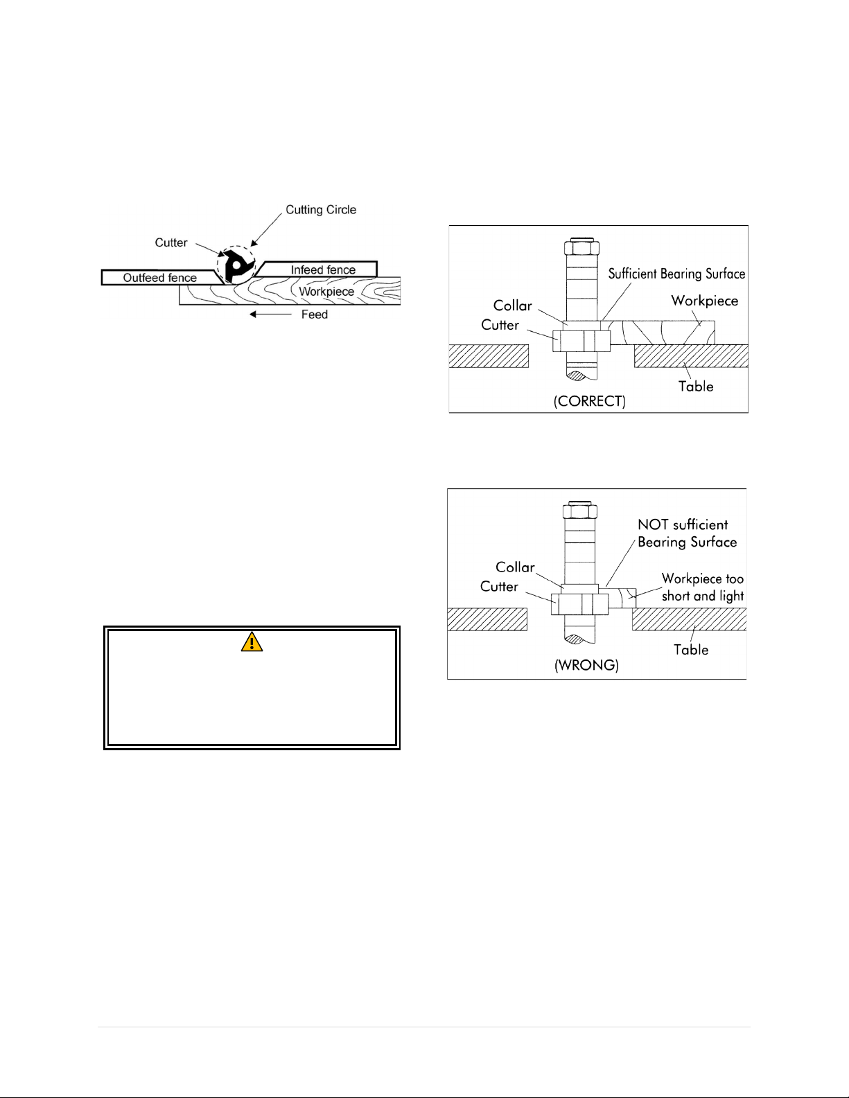
When shaping with collars, the collar must have
sufficient bearing surface.
The work must also be fairly heavy relative to the
cut being made. Never shape a short, light
workpiece against the collars.
WARNING
workpiece aga
Shaping Tall Workpieces
The height of the fence is 4-3/4” tall. For shaping
tall workpieces, mounting an auxiliary fence, or
using a tenon jig, will provide better support for
feeding workpieces safely.
34 | Page Oliver Machinery 10047VS Shaper
Page 35
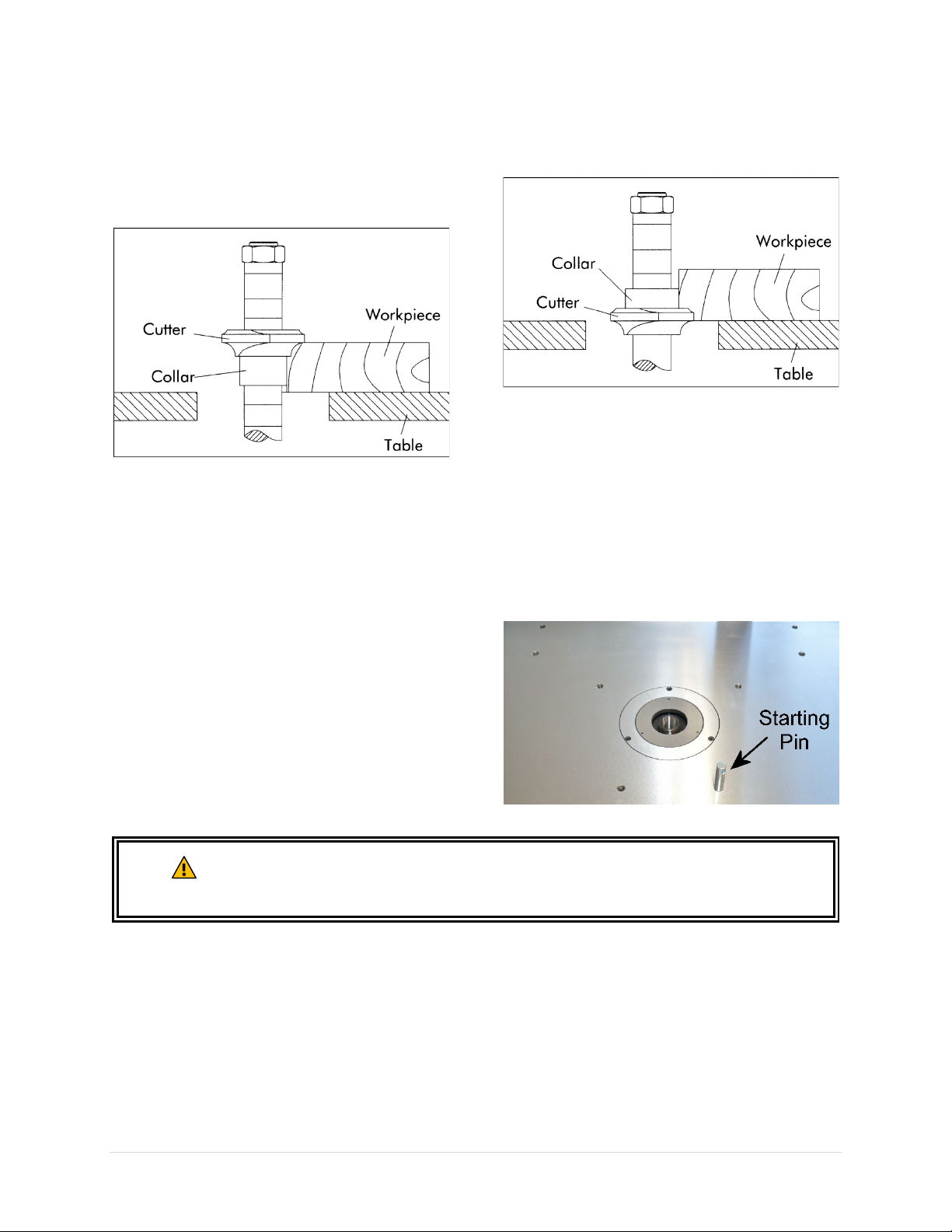
The collars may be used in any of the following
positions: above, below, or between the cutters.
When the collar is used below the cutter. The
progress of the cut can be seen throughout the
operation. However, any accidental lifting of the
work will gouge the wood and ruin the workpiece.
When the collar is used above the cutter, the cut
cannot be seen, but this method offers an
advantage in that the cut is not affected by slight
Freehand Shaping
Freehand shaping requires precise control of the
workpiece and should only be performed by advanced
users.
Use the provided starting pin or a custom-made pivot
board to initiate a cut.
Never start freehand shaping at a corner.
variations in the thickness of the stock. Also,
accidental lifting of the workpiece will not gouge
the workpiece; simply repeat the operation to
correct the mistake.
Using the collar between two cutters has the
advantages and disadvantages of the first two
procedures, and is frequently used where both
edges of the work are to be molded.
Proceed freehand shaping with extreme caution as there is a higher risk of
WARNING
10047VS Shaper OLIVERMACHINERY.NET 35 | Page
accidental cutter contact and cutter catches in the workpiece. These accidents can
result in serious injuries.
Page 36
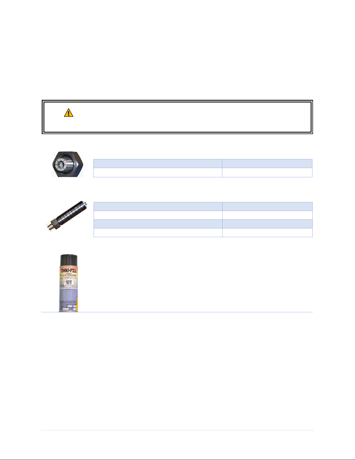
Accessories
Item
Stock Number
1/4" Collet
4705.A002
1/2" Collet
4705.A003
Item
Stock Number
1/2" Spindle
10047.A001
3/4” Spindle
10047.A002
1” Spindle
10047.A003
1-1/4 Spindle
A-10047.A006
Oliver Machinery has a collection of accessories and add-ons to enhance productivity of your shaper.
Please visit our website OLIVERMACHINERY.NET to purchase these items.
You may also call 1-800-559-5065 or email [email protected] to purchase these items. We
are available Monday through Friday, 9AM - 5PM Pacific Time.
Using unapproved accessories may cause machine to malfunction, resulting in
WARNING
Collets
Spindle Assemblies
serious injury and/or machine damage. Only use accessories recommended for
this machine.
Touchup Paint
Keeping all painted surface in good condition not only keeps your machine looks
nice, it keeps rusts away. We have pre-mixed spray paint available in Oliver-Blue
for purchase.
36 | Page Oliver Machinery 10047VS Shaper
Page 37
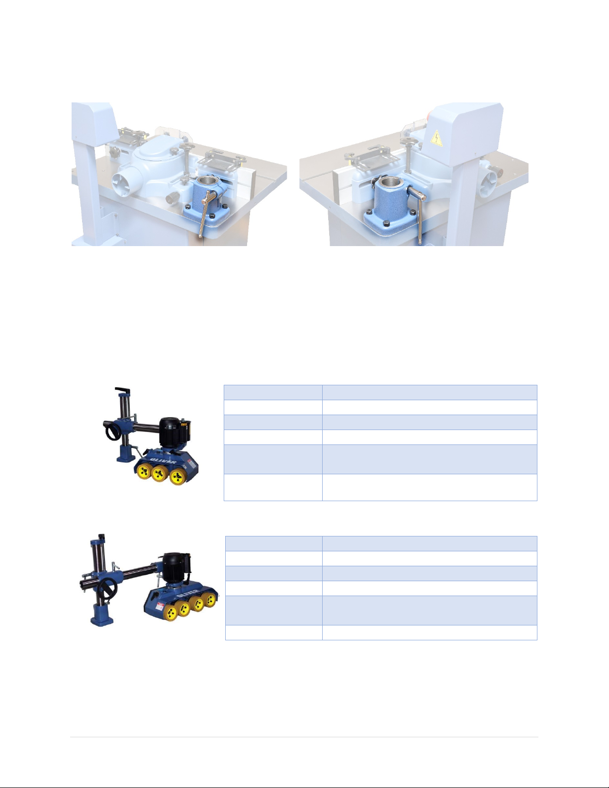
Power Feeders
Model
APF0038
Stock Number
APF0038.001 1HP, 1Ph, 230V (4.2A)
Stock Number
APF0038.002 1HP, 3Ph, 230V (3.4A)
Number of Rollers
3
Roller Size
4-3/4”(D) x 2-3/8”(W)
Feed Speed
8 Speeds:
Net Weight
137 lbs.
Model
APF0048
Stock Number
APF0048.001 1HP, 1Ph, 230V (4.2A)
Stock Number
APF0048.002 1HP, 3Ph, 230V (3.4A)
Number of Rollers
4
Roller Size
4-3/4”(D) x 2-3/8”(W)
Feed Speed
8 Speeds:
Net Weight
146 lbs.
Two power feeders are available for 10047VS Shaper. They can be installed on either side of the shaper
table in the back.
Features
• Polyurethane covered rollers provide excellent grip while protecting the work surface.
• Eight feed speeds and choice of three or four rollers to fit any application.
• Versatile stand allows adjustment of 10” in height and 18” in reach.
• Powerful TEFC motor available in single or three-phase.
• CSA Listed
6.5 / 13 / 18 / 22 / 36 / 43 / 55 / 108 FPM
Please visit our website at WWW.OLIVERMACHINERY.NET for additional recommended accessories.
10047VS Shaper OLIVERMACHINERY.NET 37 | Page
6.6 / 13 / 18 / 22 / 36 / 43 / 55 / 108 FPM
Page 38

Maintenance
Task
Frequency
Check spindle and quill for damages
Every time when changing spindle.
Check electrical cord and plug for signs of failure
Every day.
Remove dust from cabinet
Every week, or whenever there is heavy dust
buildup.
Re-coat table top with rust protectant
Every week.
Check V-belt tension and wear
Every month. Replace V-belt when it shows signs
Lubricate motor bearings
**Not needed**
Motor bearings are permanently sealed and
lubricated.
Routine maintenance keeps your shaper in optimal condition. Please follow the maintenance schedule
below, and use the maintenance record worksheet attached in the back of the manual to document all
tasks completed.
NOTICE: Maintenance schedule may vary for individual users due to different situations and safety
requirements.
of cracking or glazing.
38 | Page Oliver Machinery 10047VS Shaper
Page 39
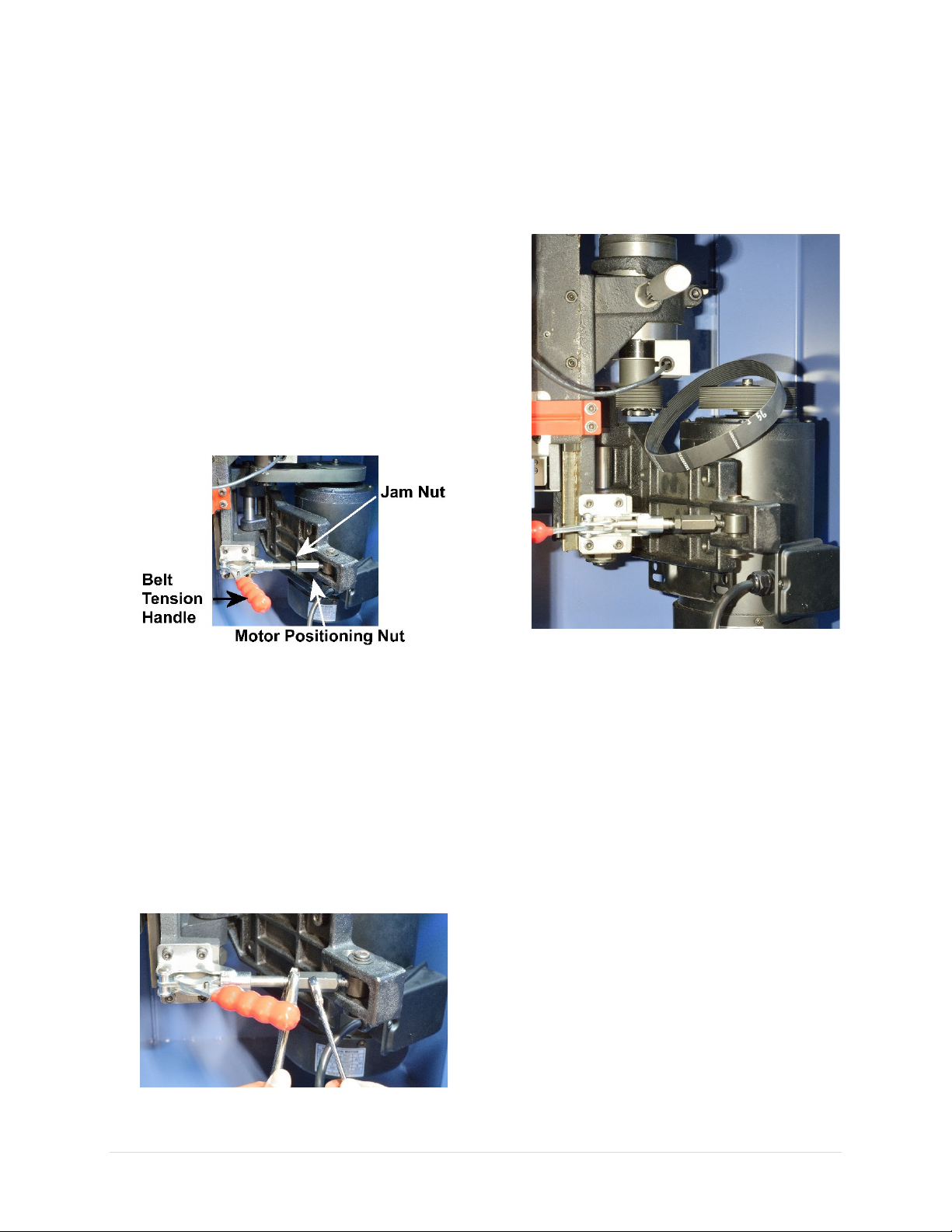
Inspect / Adjust Belt Tension
Belt tension was set in the factory and should not
require adjustments initially. Overtime, the drive
belt may stretch and therefore it should be
inspected regularly and make adjustments as
needed.
1. Disconnect machine from power source!!
2. Open cabinet door to access drive belt.
3. When pushing down into the belt midway
between the pulleys, the belt should flex by
1/8” using moderate finger pressure.
4. If belt tension needs to be adjusted, pull belt
tension handle to the left to release belt
tension, then loosen the jam nut.
Replace Drive Belt
1. Disconnect machine from power source!!
2. Open cabinet door to access drive belt.
3. Pull belt tension handle all the way to the left
to release the belt.
5. Adjust belt tension by rotating the motor
positioning nut. Make small, incremental
adjustments and check belt tension with
every 1/2 turn of the nut. To test belt tension,
hand tighten the jam nut and push the
tension lever back to the right to lock the
motor in place. If the belt tension lever is too
difficult to move, reduce belt tension by a bit.
6. Once proper belt tension is set, use one
wrench to hold motor positioning nut in
place and re-tighten the jam nut.
4. Install a new belt. Rotate the pulleys to make
sure the new belt is sitting properly on the
grooves of the pulleys.
5. Adjust belt tension. See previous section for
details.
10047VS Shaper OLIVERMACHINERY.NET 39 | Page
Page 40
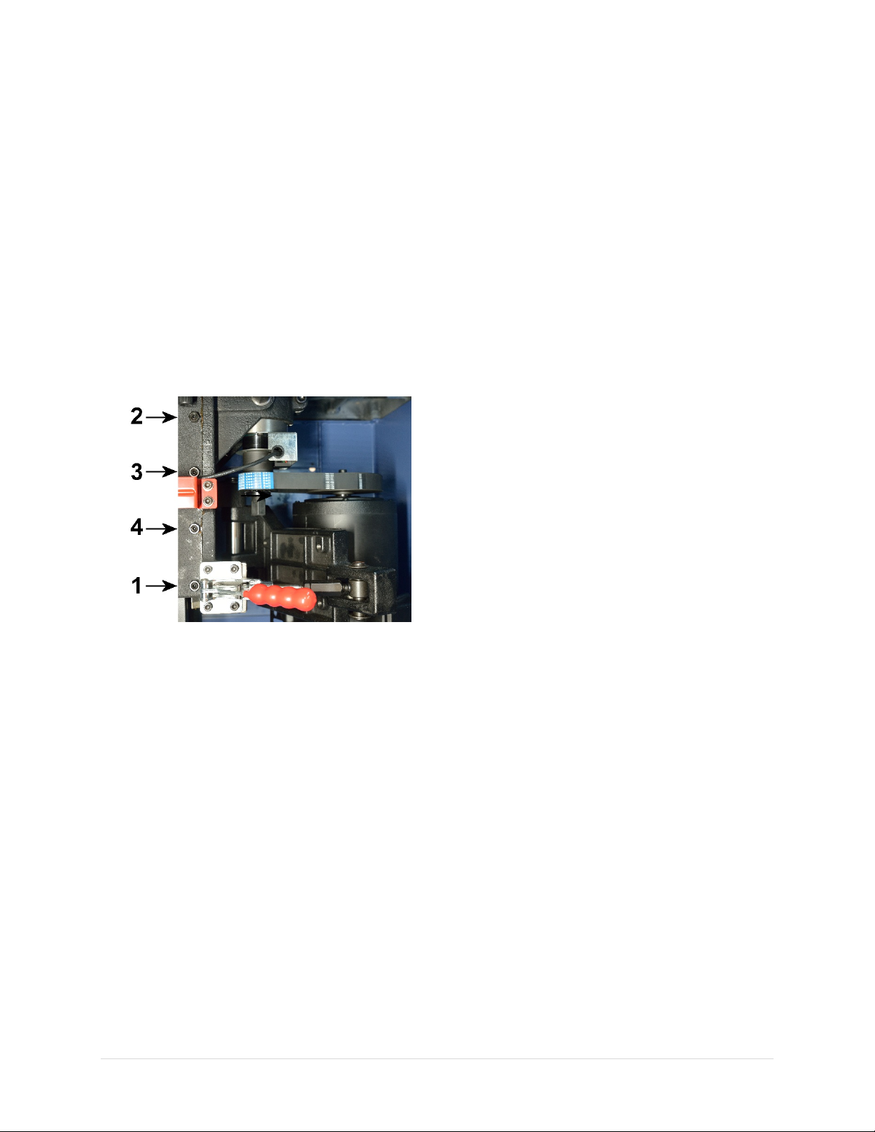
Spindle Elevator Adjustment
The gib of the spindle elevator was factory
adjusted and initially should not require
readjustment. Depending on the amount of use,
the spindle elevator may become loose and the
spindle may vibrate. In this case, it will need to
be adjusted:
1. Mark the original position of the set screws.
2. With a 13mm wrench, loosen four jam nuts
that secure the gib set screws.
3. Use a 4mm hex wrench to tighten each set
screw, 1/8 or less turn at a time. Begin with
the lowest one, followed by the uppermost
one, then the two middle set screws.
NOTICE: If the gibs are too tight, the spindle
height adjustment handwheel will be
difficult to turn. Loosen the gib set screws.
4. When the right amount of tightness is
achieved, hold the set screw in position with
a 4mm hex wrench to maintain the setting,
and tighten the jam nut with a 13mm wrench.
40 | Page Oliver Machinery 10047VS Shaper
Page 41

Troubleshooting
Problem
Possible Cause
Solution
Machine will not start
Emergency stop is
Rotate “STOP” button clockwise until it pops
Not connected to power
1. Make sure machine is plugged in.
Low voltage / current.
Have an electrician to check/repair the power
Faulty switch/motor/
Contact customer service for further
Alarm light turns on
Rotation direction switch
Set rotation direction switch to “Off”. Unplug
Machine is jammed.
Release spindle lock or remove any obstacles
Spindle does not rotate
Rotation direction switch
is in “Off” position.
Set direction to either “FOR” or “REV” for your
operation.
Machine stopped
Thermal overload
Hit STOP button and wait for at least 30
Tripped circuit breaker
or blown fuse.
Reconnect circuit. Reduce depth of cut / feed
rate before continue.
Overload protection is
Feeding stock too fast.
Feed stock more slowly.
Dull cutter.
Clean / replace cutter.
Extension cord too light
or too long.
Use a shorter / heavier cord that meets this
machine’s electrical requirements.
Machine stalls or does
Extension cord too light
Use a shorter / heavier cord that meets this
V-Belt slippage.
Increase belt tension.
Removing too much
material in one pass.
Make lighter cuts or reduce feed rate.
Cutter slippage
Tighten spindle cap screw. Ensure cutter /
Motor / capacitor issue.
Contact customer service for further
Mechanical / Electrical Issues
during operation.
engaged.
source.
capacitor.
is not in “Off” position
when machine turns on.
protection triggered.
up.
2. Check electrical panel for tripped circuit
breaker or blown fuse.
3. Ensure all electrical connections have good
contacts.
circuit.
assistance.
machine for 1 minute to reset machine.
that jams the machine. Unplug machine for 1
minute to reset machine.
seconds to cool down machine. Overload
protection will reset automatically and the
green ready light will turn on when the
machine is cooled. Reduce depth of cut / feed
rate before continue.
triggered frequently
not come up to speed
10047VS Shaper OLIVERMACHINERY.NET 41 | Page
or too long.
machine’s electrical requirements.
spindle is installed properly.
assistance.
Page 42

Difficult to turn spindle
height adjustment
Handwheel is locked.
Loosen handwheel lock knob.
Sawdust and dirt in
Brush or blow out loose dust and dirt.
needed.
Spindle gib too tight.
Adjust spindle gib tightness.
Machine vibrates
Damaged cutter.
Replace cutter.
Machine stands on
Reposition machine on flat, level surface.
Use attached rubber feet to level machine.
V-belt not tensioned
correctly.
Adjust belt tension.
Bad v-belt.
Replace v-belt.
Spindle gib wear.
Adjust spindle gib pressure.
Damaged pulley.
Replace pulley.
Improper motor
Check and adjust motor mounting.
Motor/spindle bearing
issue.
Contact customer service for further
assistance.
Problem
Possible Cause
Solution
Work pulled from hand
Inadequate stock
Hold work firmly against the table / fence.
Adjust the hold down pressure.
Use special jigs to support short stock.
For shaping short edges of a workpiece, use
Feeding work in wrong
direction.
Feed work against cutter rotation direction.
Incorrect cutter rotation
Check and correct cutter rotation direction.
Removing too much
materials in one pass.
Make lighter pass or reduce feed speed if
possible.
Outfeed fence catches
Outfeed fence not
Reduce infeed/outfeed fence offset.
Warped stock.
Ensure a flat surface is used to press against
the fence.
Edge splits off on cross
Some wood types tend
Use sharp cutters and reduce depth of cut.
Make cross-grain cuts first then finish with
grain.
Use scrap block to support at the end of a cut.
handwheel
excessively
raising mechanisms.
uneven floors.
mounting.
Lubricate spindle elevator lead screw as
Operation / Cut Quality Issues
stock
support.
miter gauge with clamp or hold down.
direction.
adjusted correctly.
grain cut
42 | Page Oliver Machinery 10047VS Shaper
to split with cross cuts.
Page 43

Stock burns
Dull cutter.
Clean / replace cutter.
Spindle speed too high.
Reduce spindle speed.
Feed rate too low.
Increase feed rate.
Cutter rotates in wrong
direction.
Correct cutter rotation direction.
Removing too much
Take light cuts; attain full depth of cut with
Raised areas on shaped
Inconsistent hold down
Keep work firmly against fence/collar/table
Use hold-downs.
Depth of cut not
Fence is not aligned.
Align infeed/outfeed fences. Check fence
Feed pressure not
Use hold-downs or feeder; keep pressure
Imperfection on the
Ensure the collar rides on a perfect edge with
Variation in height of
Variation in pressure
on table.
Keep pressure firm throughout pass, use hold-
Cuts not smooth
Dull cutter.
Replace with sharp cutter.
Spindle speed too low.
Increase RPM.
Feeding too fast.
Reduce feed rate.
Cutting against grain.
Cut with grain whenever possible.
Removing too much
Take light cuts; attain full depth of cut with
edge
uniform
cut
materials in one pass.
pressure.
uniform.
edge copied by collar.
which holds work down
several passes.
when feeding stock.
coplanarity.
against fence or collars consistent.
adequate support.
downs; make pass slowly and steadily.
Whenever possible, keep cutter under stock.
materials in one pass.
10047VS Shaper OLIVERMACHINERY.NET 43 | Page
several passes.
Page 44
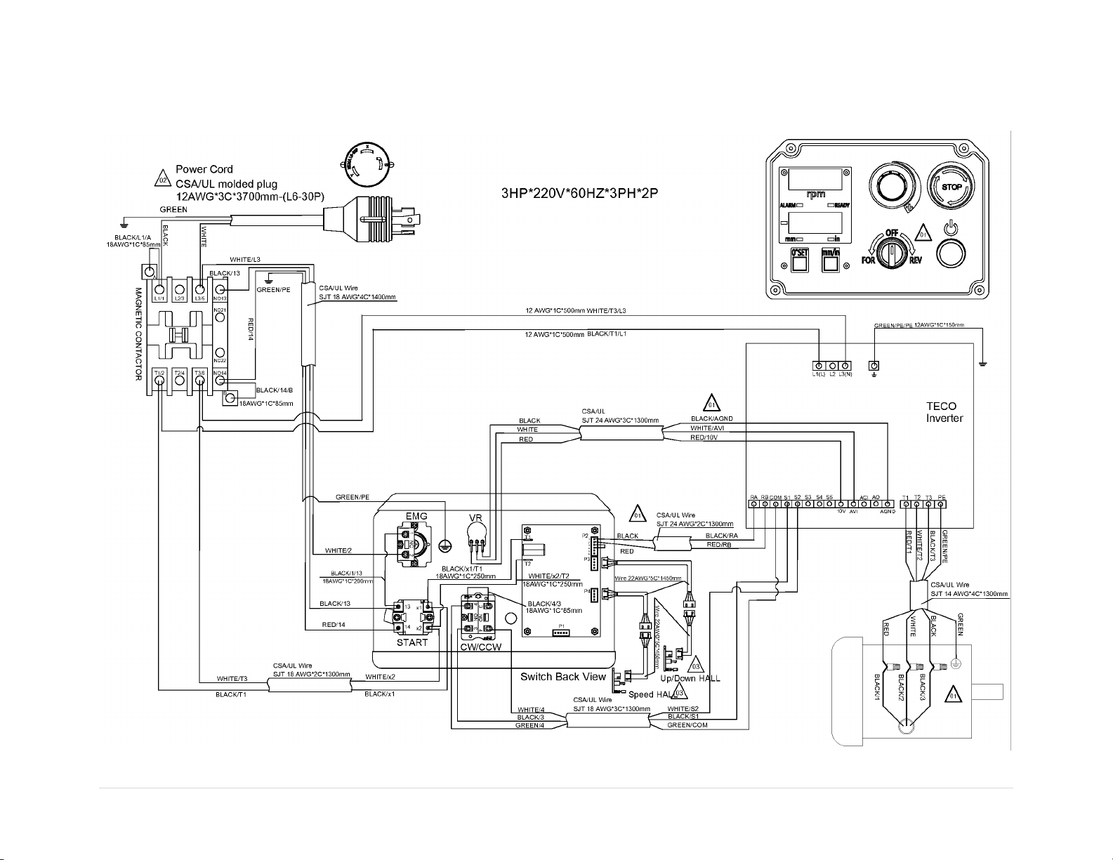
Wiring Diagram
44 | Page Oliver Machinery 10047VS Shaper
Page 45
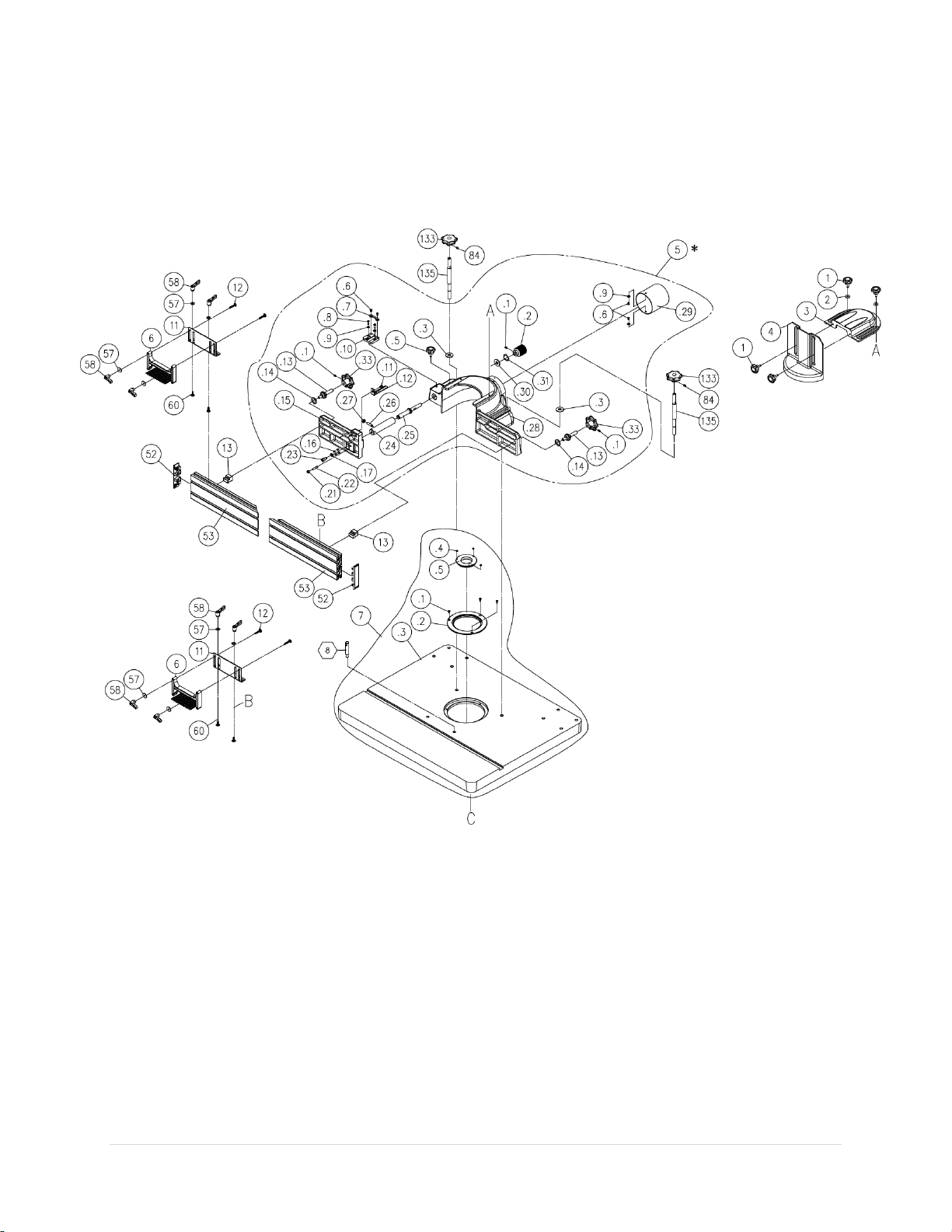
Parts List
Table and Fence
10047VS Shaper OLIVERMACHINERY.NET 45 | Page
Page 46
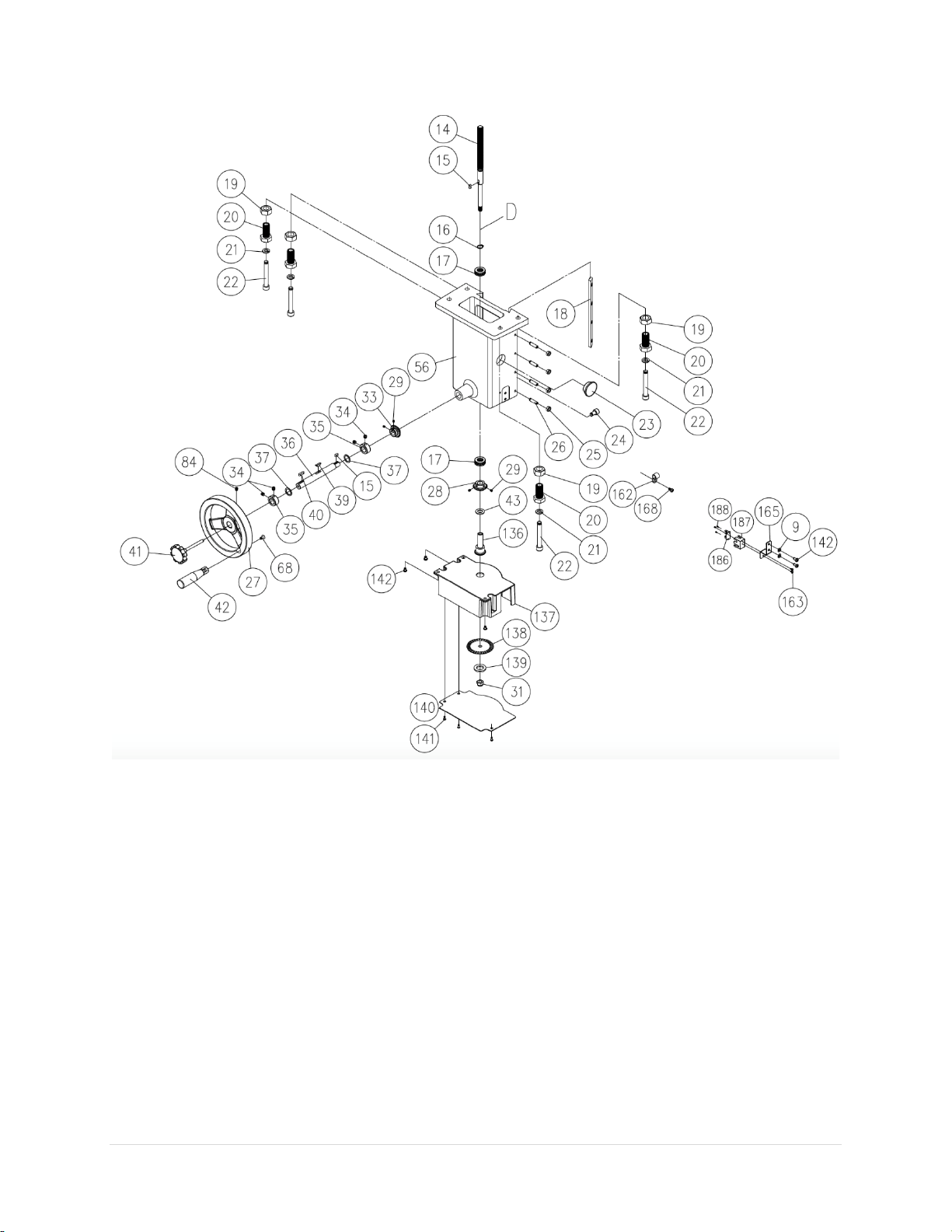
Spindle Elevator Assembly
46 | Page Oliver Machinery 10047VS Shaper
Page 47
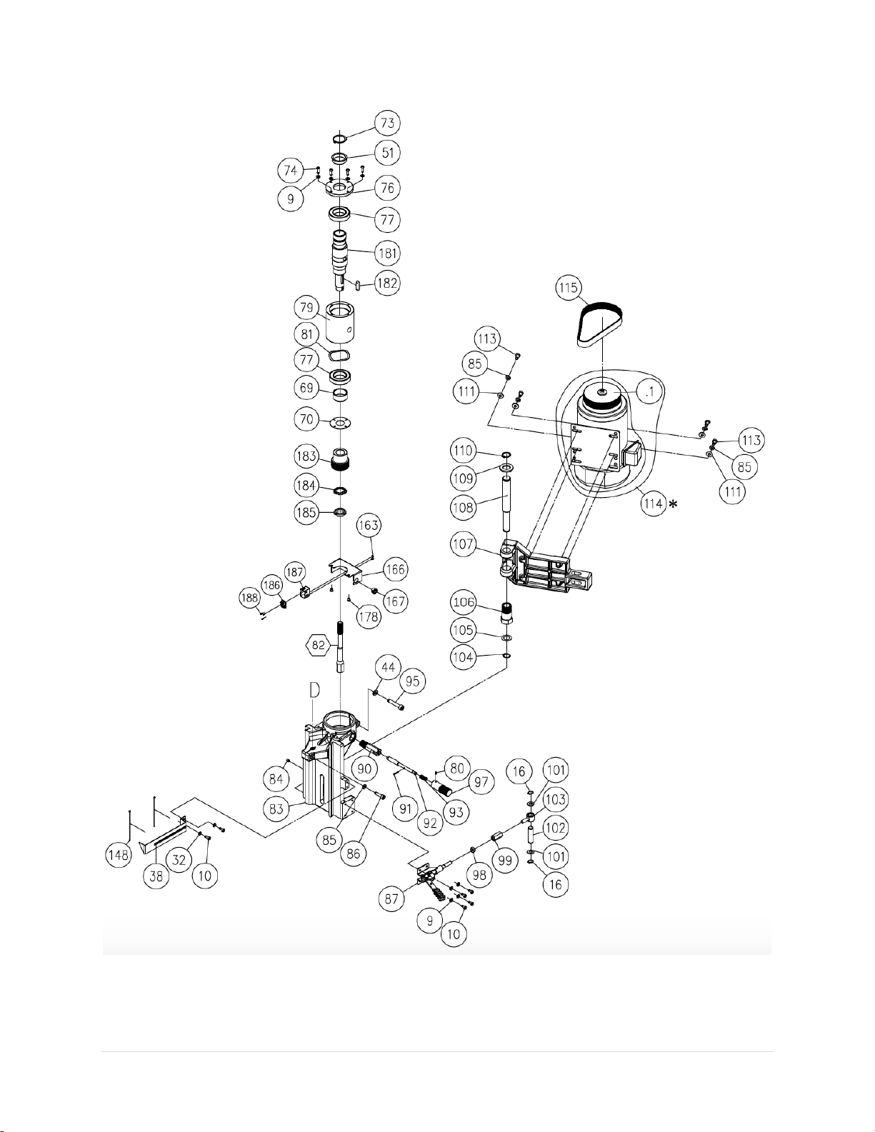
Motor and Spindle
10047VS Shaper OLIVERMACHINERY.NET 47 | Page
Page 48
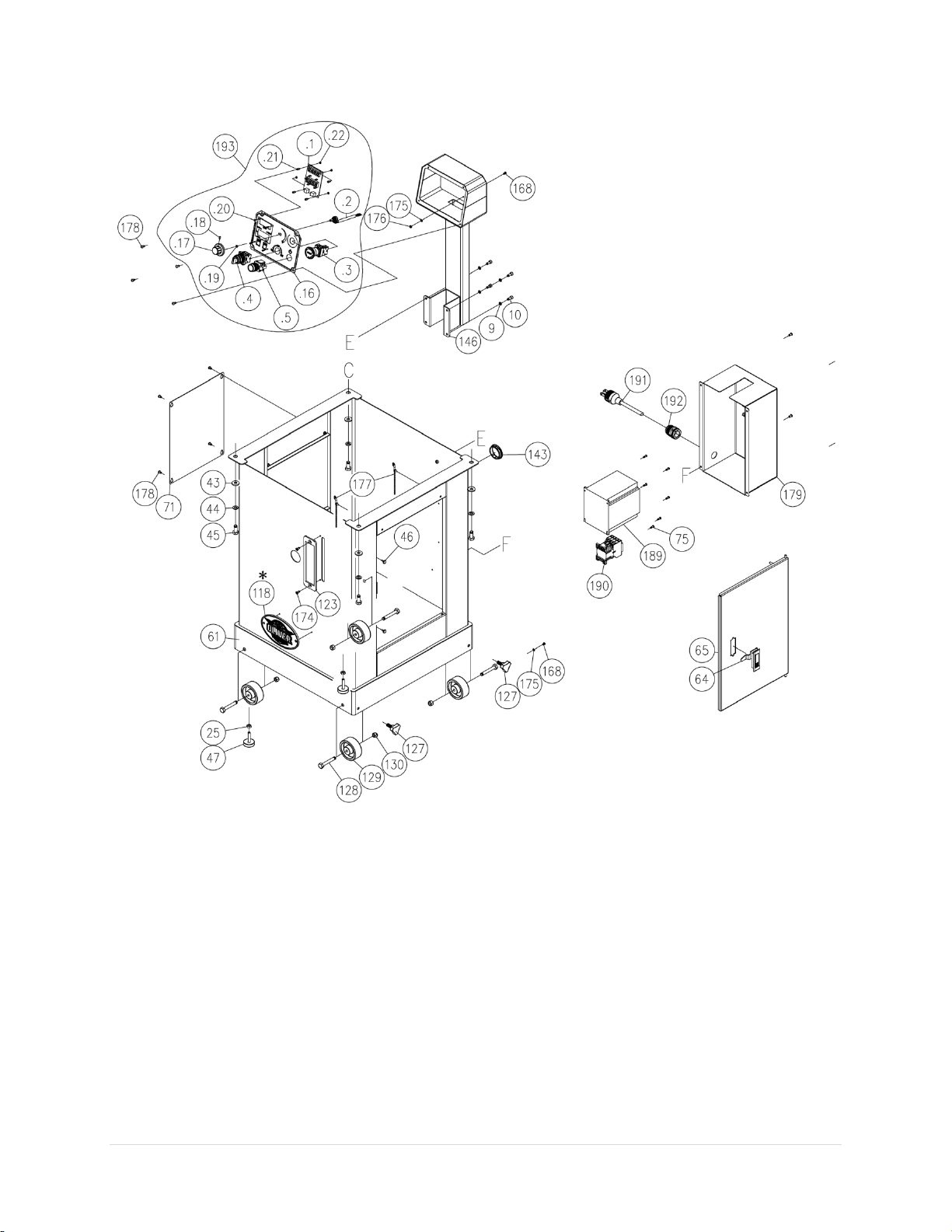
Cabinet and Control Panel
48 | Page Oliver Machinery 10047VS Shaper
Page 49
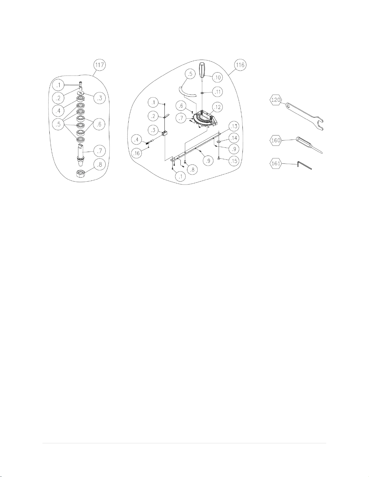
Spindle & Miter Gauge
10047VS Shaper OLIVERMACHINERY.NET 49 | Page
Page 50

Index
Part Number
Descriptions
Specifications
QTY
1
230131-000
Knob
4 2
006001-036
Flat Washer
6.7*19*2.0t
2 3 300015-000
Safety Guard Holder
1 4
250583-620
Spindle Guard
1 5
924822-000
Cutter Guard Assembly
1 5.1
001902-102
Set Screw
M6*1.0P*8
3
5.2
310160-911
Knob 1
5.3
006001-153
Flat Washer
13.5*30*3t
2
5.5
230131-000
Fix Bolt
1 5.6
000302-102
Pan Head Screw
M4*0.7P*8
4
5.7
250693-615
Slot Bar
1 5.8
000303-106
Pan Head Screw
M5*0.8P*16
2
5.9
006001-155
Flat Washer
6*12*1t
4
5.1
310161-909
Bracket
1 5.11
000303-103
Pan Head Screw
M5*0.8P*10
1
5.12
310162-909
Scale 1
5.13
361014-901
Lead Screw
2 5.14
250695-621
Plastic Washer
2 5.15
300019-000
Bracket - Left
1 5.16
000203-104
Set Screw
M6*1.0P*12
4
5.17
006305-100
Spring Washer
8.2*15.4
1
5.21
008005-100
Hex Nut
M6*1.0P(10B*5H)
1
5.22
000203-109
Set Screw
M6*1.0P*30
1
5.23
000104-104
Cap Screw
M8*1.25P*16
1
5.24
360855-000
Bracket Shaft
1 5.25
360857-901
Adjust Screw
1 5.26
230258-901
Position Set Screw
M8*1.25P
1
5.27
008006-100
Hex Nut
M8*1.25P(13B*6.5H)
1
5.28
300020-000
Cutter Guard
1 5.29
190155-000
Dust Chute
1 5.3
006001-096
Flat Washer
13.5*32*3t
1
5.31
006708-100
Wave Washer
12.7*18.1
1
5.33
240080-904
Knob 2 6 250608-000
Featherboard
TS-35
2
7
922139-000
Table Assy
1
7.1
002101-101
Flat Head Screw
M5*0.8P*20
3
7.2
050894-902
Insert Ring (Large)
1
7.3
050891-000
Table
1 7.4
001904-102
Set Screw
M4*0.7P*4
3
7.5
050893-902
Insert Ring (Small)
1
8
360735-905
Starter Pin
1 9
006303-100
Spring Washer
6.5*10.5
14
10
000103-103
Cap Screw
M6*1.0P*12
10
11
172031-901
Bracket
2 12
001004-203
Carriage Bolt
M5*0.8P*30L
4
13
130233-903
Slide 2
50 | Page Oliver Machinery 10047VS Shaper
Page 51

Index
Part Number
Descriptions
Specifications
QTY
14
360714-901
Up/Down Shaft
1 15
012003-003
Key
5*5*12
2
16
010006-000
Retaining Ring
STW-15
3
17
031006-001
Bearing
51202
2
18
050696-000
Gib 1
19
008017-100
Hex Nut
M20*1.5P(30B*16H)
4
20
380647-902
Adjust Screw
M20*1.5P
4
21
006308-100
Spring Washer
12.2*21.6
4
22
000106-112
Cap Screw
M12*1.75P*80
4
23
250159-615
Plug 1
24
002604-101
Pan Head Lock Screw
M10*1.5P*20
1
25
008006-100
Hex Nut
M8*1.25P(13B*6.5H)
6
26
000204-109
Set Screw
M8*1.25P*40
4
27
240077-000
Handwheel
1 28
380767-000
Bevel Gear
(Left Thread)
1
29
001901-101
Set Screw
M5*0.8P*5
4
31
008307-100
Lock Nut
M10*1.25P(17B*12H)
1
32
006003-023
Flat Washer
6.3*13*2t
2
33
380768-000
Bevel Gear
(Right Thread)
1
34
004403-103
Set Screw
5/16"-18NC*5/16"
4
35
360376-901
Fix Ring
2 36
360721-901
Lead Screw
1 37
006006-106
Flat Washer
19.1*25.4*1.6
2
38
172321-156
Pointer
1
39
130061-000
Key 1
40
012003-007
Key
5*5*20
1
41
230128-916
Lock Handle
1 42
230046-000
Handle
1 43
006001-075
Flat Washer
10.3*22*2.0t
5
44
006307-100
Spring Washer
10.2*18.5
5
45
000004-202
Hex Screw
M10*1.5P*25
4
46
340007-615
Spacer
2 47
230109-615
Packing Screw
2 51
190164-901
Bushing
1 52
250593-615
End Cap
2 53
310159-909
Fence
2 56
050692-008
Support
1 57
006001-127
Flat Washer
5.5*22*2.0t
8
58
230178-000
Lock Handle
8 60
001004-202
Carriage Bolt
M5*0.8P*16L
4
61
174803-000
Stand
1 64
230134-000
Latch 1
65
172841-000
Door 1
68
000702-102
Socket Hex Screw
M6*1.0P*12
1
69
190165-901
Bushing
1 70
174804-000
Plate 1
10047VS Shaper OLIVERMACHINERY.NET 51 | Page
Page 52

Index
Part Number
Descriptions
Specifications
QTY
71
173265-000
Side Cover
1 73
010025-000
S Ring
STW-40
1
74
000801-104
Pan Head Hex Screw
4 75
000302-204
Pan Head Phillips Screw
6 76
050892-901
Bearing Housing
1 77
033711-002
Ball Bearing
6008-2NSE
2
79
051046-000
Quill 1
80
000203-102
Set Screw
M6*1.0P*8
1
81
006725-100
Wave Washer
1 82
380505-902
Draw Bar
1 83
050691-008
Arbor Shaft Bracket
1 84
001902-102
Set Screw
M6*1.0P*8
4
85
006305-100
Spring Washer
8.2*13.7
5
86
000104-110
Cap Screw
M8*1.25P*30
1
87
230349-000
Belt Tension Handle
GH-31501
1
90
380511-901
Connector
1 91
011002-105
Spring Pin
4*20
1
92
360724-901
Rod 1
93
280151-905
Spring
1 95
000105-106
Cap Screw
M10*1.5P*55
1
97
300013-000
Handle
1 98
008007-100
Hex Nut
M10*1.5P(17B*8H)
1
99
380507-901
Hex Bushing
1 101
006001-125
Flat Washer
15.5*25*2.5t
2
102
360719-901
Connector
1 103
380513-901
Shaft
1 104
010010-000
Retaining Ring
STW-20
1
105
006001-142
Flat Washer
21*38*3t
1
106
380648-902
Adjustment Bolt
M30*1.5P
1
107
050689-008
Motor Bracket
1 108
360720-901
Shaft 1
109
006001-118
Flat Washer
25*44*4t
1
110
010011-000
Retaining Ring
STW-25
1
111
006001-042
Flat Washer
8.2*22*4.5t
4
113
000003-105
Hex Screw
M8*1.25P*25
4
114.1
901218-000
Motor Assembly
3HP*220-240V*60HZ*3PH*2P
1
114.1
381433-902
Motor Pulley
1 115
014318-000
V Belt
230 J10
1
116
924589-000
Miter Gauge Assy
1 116.1
003303-105
Pan Head Screw
3/16"-24NC*3/8"
3
116.2
250193-620
Pointer
1 116.3
130053-903
Spacer
1 116.4
360381-901
Angle Set Bar
1 116.5
571151-000
Miter Scale
1 116.6
003305-106
Pan Head Screw
5/32"-32NC*5/8"
3
116.7
009001-100
Hex Nut
5/32"-32NC
3
52 | Page Oliver Machinery 10047VS Shaper
Page 53

Index
Part Number
Descriptions
Specifications
QTY
116.8
290017-901
Shoulder Screw
1 116.9
230222-901
Fix Ball
3 116.1
230140-615
Handle
1 116.11
006002-051
Flat Washer
8.5*18*3t
1
116.12
090067-008
Miter Gauge Body
1 116.13
380614-904
Slot Bar
1 116.14
130380-903
Ring 1
116.15
000403-101
Flat Head Screw
M6*1.0P*8
1
116.16
043716-000
O-Ring
AS008
1
117
10047.A006
1-1/4" Arbor Assy
1 117.1
000105-103
Cap Screw
M10*1.5P*30
1
117.2
011102-103
Pin
4.0*20
2
117.3
171848-902
Washer
10.5*45*5t
1
117.4
380531-901
Bushing
1 117.5
380039-901
Spacer
4 117.6
380038-901
Spacer
2 117.7
220096-000
1-1/4" Arbor
1 117.8
380818-901
Arbor Nut
1 118
SS08-10
Machine Labels
120
171895-904
Wrench
50mm
1
123
174805-904
Scale Frame
1 127
230388-000
Bolt
SS400
4
128
000003-313
Hex Screw
M8*1.25P*60 (Thread length 30)
4
129
250399-615
Wheel
4 130
008306-100
Lock Nut
M8*1.25P
4
133
240080-904
Knob 2
135
361015-901
Shaft 2
136
360809-902
Bushing
1 137
250630-000
Anti-Dust Cover
1 138
174919-000
Sensor Plate
1 139
172166-901
Packing Screw
1 140
172095-000
Anti-Dust Plate
1 141
001102-604
Self-Tapping Screw
M4*1.59P*12
3
142
000304-203
Pan Head Phillips Screw
M6*1.0P*12
5
143
021809-000
Ring
SB-50
1
146
174806-000
Switch Support
1 148
021004-000
Lock Tie
ALT-085S-B Black
2
160
040401-000
Screwdriver
#1*75
1
161
040007-000
Allen Wrench
8*100mm
1
162
021102-000
Wire Buckle
ACC-2.5
1
163
001101-205
Self-Tapping Screw
M3*1.06P*6
4
165
171986-000
Bracket
1 166
174808-000
Anti-Dust Upper Cover
1 167
021812-000
Ring
NB-1216C
1
168
000302-202
Pan Head Phillips Screw
M4*0.7P*8
3
174
000402-104
Pan Head Phillips Screw
M5*0.8P*12
2
10047VS Shaper OLIVERMACHINERY.NET 53 | Page
Page 54

Index
Part Number
Descriptions
Specifications
QTY
175
006501-200
Teethed Washer
4.3*8.5(BW-4)
2
176
008002-200
Hex Nut
M4*0.7P(7B*3.2H)
1
177
230297-615
Chain 2
178
000804-103
Pan Head Hex Screw
M5*0.8P*10
14
179
174809-000
Rear Access Cover
1 181
360912-901
Shaft 1
182
012005-003
Key
8*7*35
1
183
381432-902
Pulley 1
184
006802-100
Washer
25 1 185
008201-100
Nut
M25*1.5P
1
186
491196-000
Sensor
CT 2 187
250665-615
Up/Down Sensor
2 188
001106-601
Self-Tapping Screw
M2*0.63P*6L
6
189
491165-000
Inverter
TECO L510-203-SH1(2.2KW;1PH
1
190
490657-000
Magnetic Contact
MA-18(220V-240V)
1
191
453153-002
Cable w/CSA/UL plug
SJT 12AWG*3C*3700mn-(L6-30P)
1
192
023701-007
Strain Relief
MG25AS-14B (w/nut)
1
193
950805-000
Switch Plate Assembly
1 193.1
491164-000
LCM Display
1
193.2
950796-000
Variable Speed Button
Assembly
1 193.3
490591-000
Emergency Stop Button
KB2(RED STOP)+1b contact point
(220V)(Ø22)
1
193.4
490941-000
3 Speed Switch
Black Ø22 KB2-ED33(2a)(KEYON)
1
193.5
490183-000
Lightening Start Switch
Green (220V)
1
193.16
924818-000
Switch Plate Assembly
1 193.17
251375-675
Speed Adjust Knob
1 193.18
001904-104
Set Lock Screw
M4*0.7P*8L
1
193.19
043311-000
O-Ring (P Type)
P5 1 193.2
000806-103
Pan Head Hex Screw
M3*0.5P*8L
4
193.21
491160-000
Plastic Rod
HTS-308(M3) (KSS)
4
193.22
491166-000
Plastic Nut
PN-3(M3) (KSS)
4
200V 3HP)
54 | Page Oliver Machinery 10047VS Shaper
Page 55

Maintenance Record
Date
Task
Operator
10047VS Shaper OLIVERMACHINERY.NET 55 | Page
Page 56

Notes
56 | Page Oliver Machinery 10047VS Shaper
Page 57

Warranty and Service
Oliver Machinery makes every effort to assure that its equipment meets the highest possible standards
of quality and durability. All products sold by Oliver Machinery are warranted to the original customer to
be free from defects for a period of two (2) years on all parts excluding electronics and motors which are
warranted for one (1) year from the date of shipment. Oliver Machinery’s obligation under this warranty
shall be exclusively limited to repairing or replacing products or parts or components, at its sole option,
determined by Oliver Machinery to be defective. Oliver Machinery shall not be required to provide other
form of indemnity or compensation including but not limited to compensatory damages.
This warranty does not apply to defects due to direct or indirect misuse, abuse, negligence, accidents,
unauthorized repairs, alternation outside our facilities, lack of maintenance, acts of nature, or items that
would normally be consumed or require replacement due to normal wear and tear.
OTHER TERMS
To obtain and exercise the warranty right, please call 800-559-5065 or fill out warranty request form
online at www.olivermachinery.net
Warranty parts are shipped via Parcel or Ground. Additional charge will occur and charge to customers if
express shipping is required.
DISCLAIMER
Under no circumstances shall Oliver Machinery be liable for death, personal or property injury or damages
arising from the use of its products.
.
Oliver Machinery reserves the right to make changes without prior notice to its products to improve
function or performance or design.
FOR MORE INFORMATION
If you need assistance or have questions beyond what is covered in the scope of this warranty information,
please call 800-559-5065 or email us at [email protected]
.
10047VS Shaper OLIVERMACHINERY.NET 57 | Page
Page 58

Oliver Machinery is always adding new Industrial Woodworking products to the line.
For complete, up-to-date product information, visit us online at:
WWW.OLIVERMACHINERY.NET
or call toll free 1-800-559-5065
** SAVE THIS MANUAL FOR FUTURE REFERENCES. **
 Loading...