

Page 1

4260
12” Parallelogram Jointer
Owner’s Manual
Oliver Machinery M-4260 9/2019
Page 2

Warranty
Oliver makes every effort possible to assure that its equipment meets the highest possible
standards of quality and durability. All products sold by Oliver are warranted to the original
customer to be free from defects for a period of 2 (two) years on all parts, excluding electronics
and motors, which are warranted for 1 year. Oliver’s obligation under this warranty shall be
exclusively limited to repairing or replacing (at Oliver’s option) products which are determined by
Oliver to be defective upon delivery F.O.B. (return freight paid by customer) to Oliver, and on
inspection by Oliver. This warranty does not apply to defects due, directly or indirectly, to misuse,
abuse, negligence, accidents, unauthorized repairs, alterations, lack of maintenance, acts of
nature, or items that would normally be consumed or require replacement due to normal wear. In
no event shall Oliver be liable for death, personal or property injury, or damages arising from the
use of its products.
Warning
Read this manual thoroughly before operating the machine. Oliver Machinery disclaims any
liability for machines that have been altered or abused. Oliver Machinery reserves the right to
effect at any time, without prior notice, those alterations to parts, fittings, and accessory
equipment which they may deem necessary for any reason whatsoever.
For More Information
Oliver Machinery is always adding new Industrial Woodworking products to the line. For
complete, up-to-date product information, check with your local Oliver Machinery distributor, or
visit www.olivermachinery.net
Page 3

Table of Contents
SAFETY INSTRUCTIONS ................................................................................................................... 2
Uncrating the Machine .......................................................................................................................... 5
Machine Preparation and Setup .......................................................................................................... 5
Dust Collection ....................................................................................................................................... 5
Electrical Connections .......................................................................................................................... 6
Grounding Instrctions ............................................................................................................................ 6
On/Off Switch ......................................................................................................................................... 7
Control Box ............................................................................................................................................. 7
Cutterhead Guard Installing & Removal ............................................................................................ 7
Cutterhead .............................................................................................................................................. 8
Cutterhead Removal ............................................................................................................................. 8
Fence ....................................................................................................................................................... 9
Hand Safety and Placement .............................................................................................................. 10
Jointing .................................................................................................................................................. 10
Direction of the Grain .......................................................................................................................... 10
Edging ....................................................................................................................................................11
Facing .....................................................................................................................................................11
Beveling .................................................................................................................................................11
Rabbeting .............................................................................................................................................. 12
Adjusting the Infeed Table Height ..................................................................................................... 12
Adjusting V-Belts ................................................................................................................................. 12
Lubrication............................................................................................................................................ 13
Coplaner Adjusting ...............................................................................................................................13
Coplaner Adjusting Continued .......................................................................................................... 14
Basic Operations ................................................................................................................................ 15
Push Blocks .......................................................................................................................................... 15
Trouble shooting .................................................................................................................................. 18
PARTS DIAGRAMS ............................................................................................................................ 19
PARTS LIST ......................................................................................................................................... 22
1
Page 4

SAFETY INSTRUCTIONS
For Your Safety Read Instruction Manual Before Operating Jointer
As with all machines, there is a certain amount of hazard involved with the use of this jointer. Use the
machine with the respect and caution demanded where safety precautions are concerned. When normal
safety precautions are overlooked or ignored, personal injury to the operator can result.
Wear eye protection.
Never make jointing , planning, or rabbeting cut deeper than 1/8 in.
Always use hold-down/push blocks for jointing material narrower than 3 inches, or planning material
thinner than 3inches.
Never perform jointing. Planning, or rabbeting cuts on pieces shorter than 8 inches (203 mm) in
length.
Keep guards in place and in working order.
Remove adjusting keys and wrenches. Form habit of checking to see that keys and adjusting
wrenches are removed from tool before turning it on .
Keep work area clean. Cluttered areas and benches invite accidents.
Don’t use in dangerous environment. Don’t use power tools in damp or wet locations, or expose them
to rain. Keep work area well lighted.
Keep children away. All visitors should be kept safe distance from work area.
Make workshop kid proof with padlocks, master switches, or by removing starter keys.
Don’t force tool. It will do the job better and safer at the rate for which it was designed.
Use right tool. Don’t force tool or attachment to do a job for which it was not designed.
Use proper extension cord. Make sure your extension cord is in good condition. When using an
extension cord, be sure to use one heavy enough to carry the current your product will draw. An
undersized cord will cause a drop in line voltage resulting in loss of power and overheating Table
(see Figure 9) shows the correct size to use depending on cord length and nameplate ampere rating.
If in doubt, use the next heavier gage. The smaller the gage number, the heavier the cord.
Wear proper apparel. Do not wear loose clothing, gloves, neckties, rings, bracelets, or other jewelry
which may get caught in moving parts. Nonslip footwear is recommended. Wear protective hair
covering to contain long hair.
Always use safety glasses. Also use face or dust mask if cutting operation is dusty. Everyday
eyeglasses only have impact resistant lenses, they are NOT safety glasses.
Secure work. Use clamps or a vise to hold work when practical. It’s safer than using your hand and it
frees both hands to operate tool.
Don’t overreach. Keep proper footing and balance at all times.
2
Page 5

Maintain tools with care. Keep tools sharp and clean for best and safest performance. Follow
instructions for lubricating and changing accessories.
Disconnect tools before servicing; when changing accessories, such as blades, bits, cutters, and the
like.
Reduce the risk of unintentional starting. Make sure switch is in off position before plugging in.
Use recommended accessories. Consult the owner’s manual for recommended accessories. The use
of improper accessories may cause risk of injury to persons.
Never stand on tool. Serious injury could occur if the tool is tipped or if the cutting tool is
unintentionally contacted.
Check damaged parts. Before further use of the tools, a guard or other part that is damaged should
be carefully checked to determine that it will operate properly and perform its intended function –
check for alignment of moving parts, binding of moving parts, breakage of parts, mounting , and any
other conditions that may affect its operation. A guard or other part that is damaged should be
properly repaired or replaced.
Direction of feed. Feed work into a blade or cutter against the direction of rotation of the blade or
cutter only.
Never leave tool running unattended. Turn power off. Don’t leave tool until it comes to a complete stop.
Do not perform jointing operation on material shorter than 10 in , narrower than 3/4 in, or less than 1/4
in thick.
Maintain the proper relationships of infeed and outfeed table surfaces and cutter head knife path.
Support the work piece adequately at all times during operation; maintain control of the work at all
times.
Do not back the work toword the infeed table.
Do not attempt to perform an abnormal or a little-used operation without study and the use of adequate
hold-down/push blocks, jigs, fixtures, stops and the like.
3
Page 6
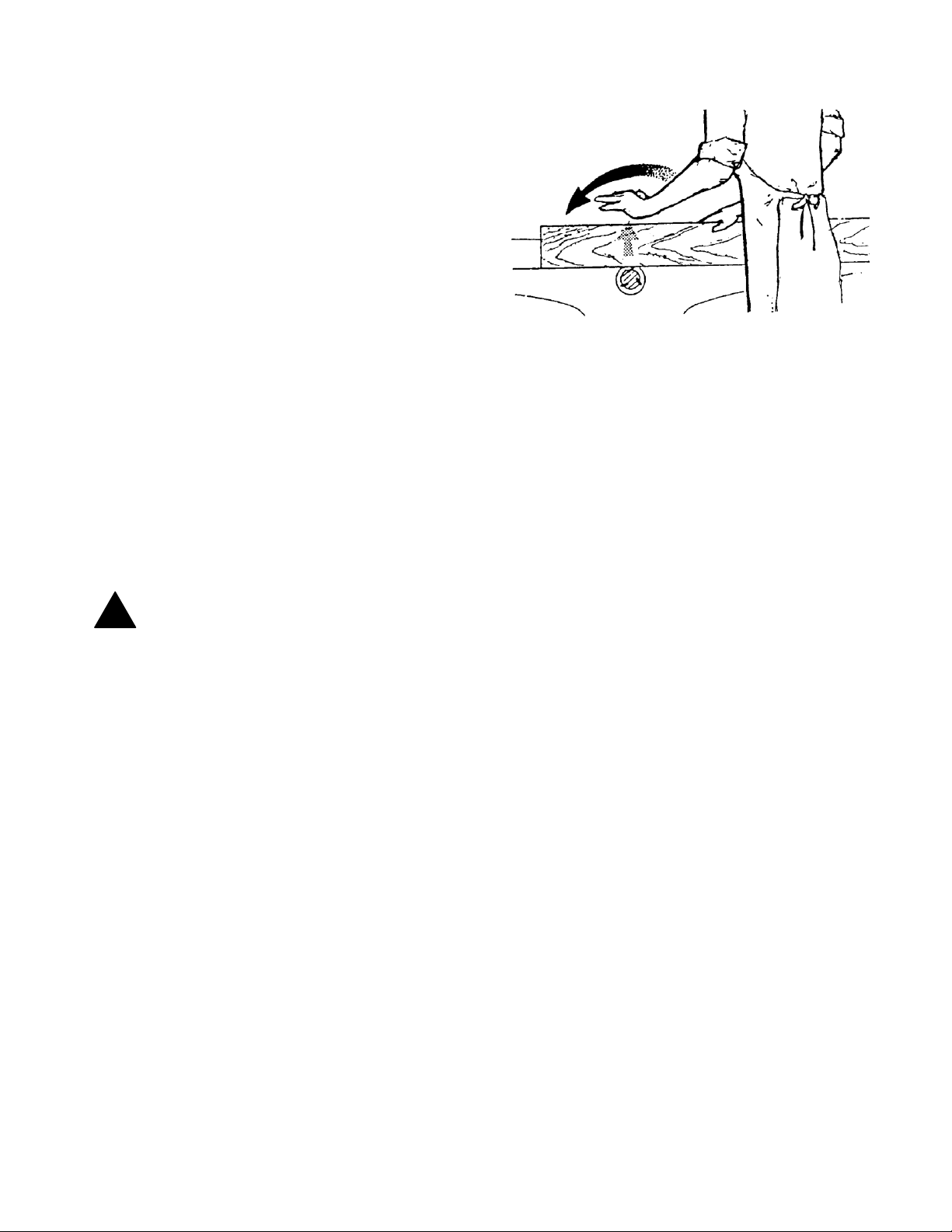
Hand safety. It is good practice to move the hands
!
in an alternate motion from back to front as the
work continues through the cut. Never pass the
hands directly over the cutter knife. As one hand
approaches the knives remove it from the stock in
an arc motion and place it back on the stock in a
position beyond the cutterknife.
Three inch rule. When working a piece of wood on
the jointer, follow the 3 inch radius rule. The hands
must never be closer than 3 inches to the cutter
head.
Health hazards. Some dust created by power
sanding, sawing, grinding, drilling and other construction activities contains chemicals known to cause
cancer, birth defects or other reproductive harm. Some examples of these chemicals are:
* Lead from lead-based paint.
* Crystalline silica from bricks and cement and other masonry products.
* Arsenic and chromium from chemically-treated lumber.
Your risk from these exposures varies, depending on how often you do this type of work. To reduce
your exposure to these chemicals, work in a well-ventilated area, and work with approved safety
equipment, such
as those dust masks that are specifically designed to filter out microscopic particles.
Familiarize yourself with the following safety notices used in this manual:
CAUTION: (This means that if precautions are not heeded, it may result in minor or moderate injury
and/or possible machine damage)
WARNING: (This means that if precautions are not heeded, it could result in serious injury or
!
possibly even death).
4
Page 7
Uncrating the Machine
Uncrate the machine and inspect the unit for
signs of shipping damage. If damage is found,
contact your dealer immediately. Unbolt the
machine from the pallet. Retain all
packaging materials in case it becomes
necessary to ship the machine to another site.
Moving the Machine into Place
Do not lift the jointer by the tables
pallet to the shop position. This may change
coplanar alignment and will need to be
corrected before use. See page 13 for
coplanar adjustments.
To move the machine, use the supplied 3/4”
lifting bars by placing them through the stand
and securing with properly rated straps on
each side.
from the
WARNING: The equipment used to lift this
machine must have a rated capacity at or
above the weight of the jointer. Failure to
comply may cause serious damage and injury.
Machine Preparation and Setup
The jointer must be positioned on a smooth,
level surface. The area must be well lit and
have plenty of room to maneuver with large
pieces of wood.
Level the jointer front to back and side to side
using a level placed on the table. Use shims
under the corners, if necessary, but make sure
the jointer is stable before being placed into
service.
Clean all rust protected surfaces with a
commercial solvent. Do not use acetone,
gasoline, lacquer thinner or any type of
flammable solvent, or a cleaner that may
damage paint. Cover cleaned surfaces with
WD-40 or a 20W machine oil.
Dust Collection
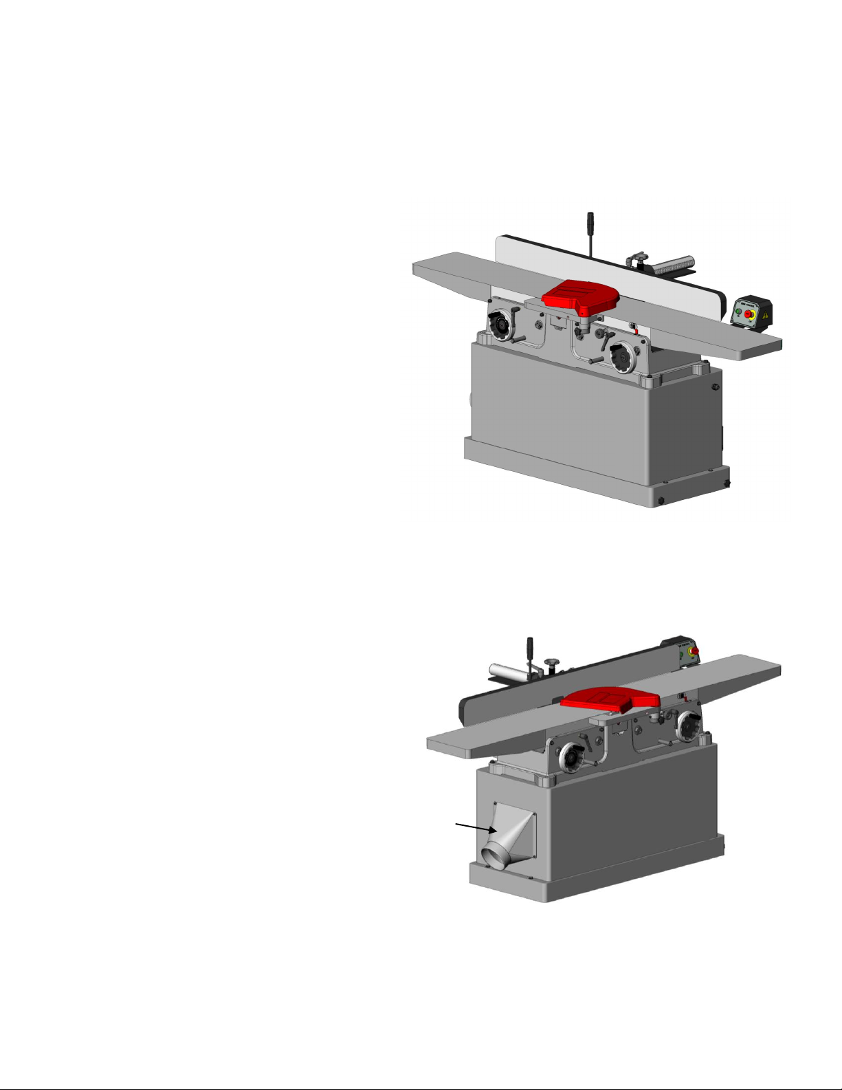
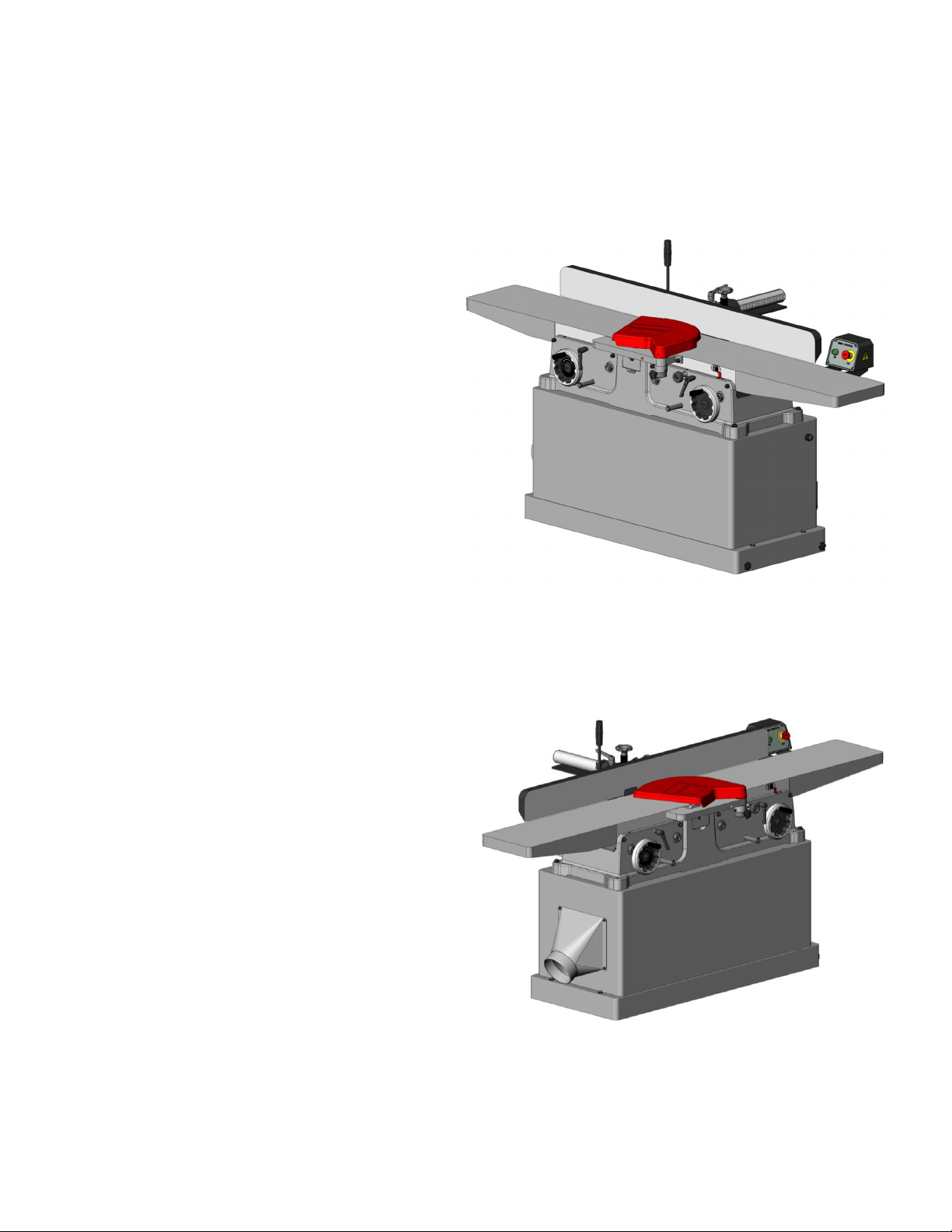
The 6” dust collection port (A, Fig. 1) is located
below the outfeed table. Typically flex hose is
used to run from this point to a central trunk
line.
A
Fig. 1
Note: Do not operate the jointer without
dust collection.
Fig. 1
5
Page 8
Electrical Connections
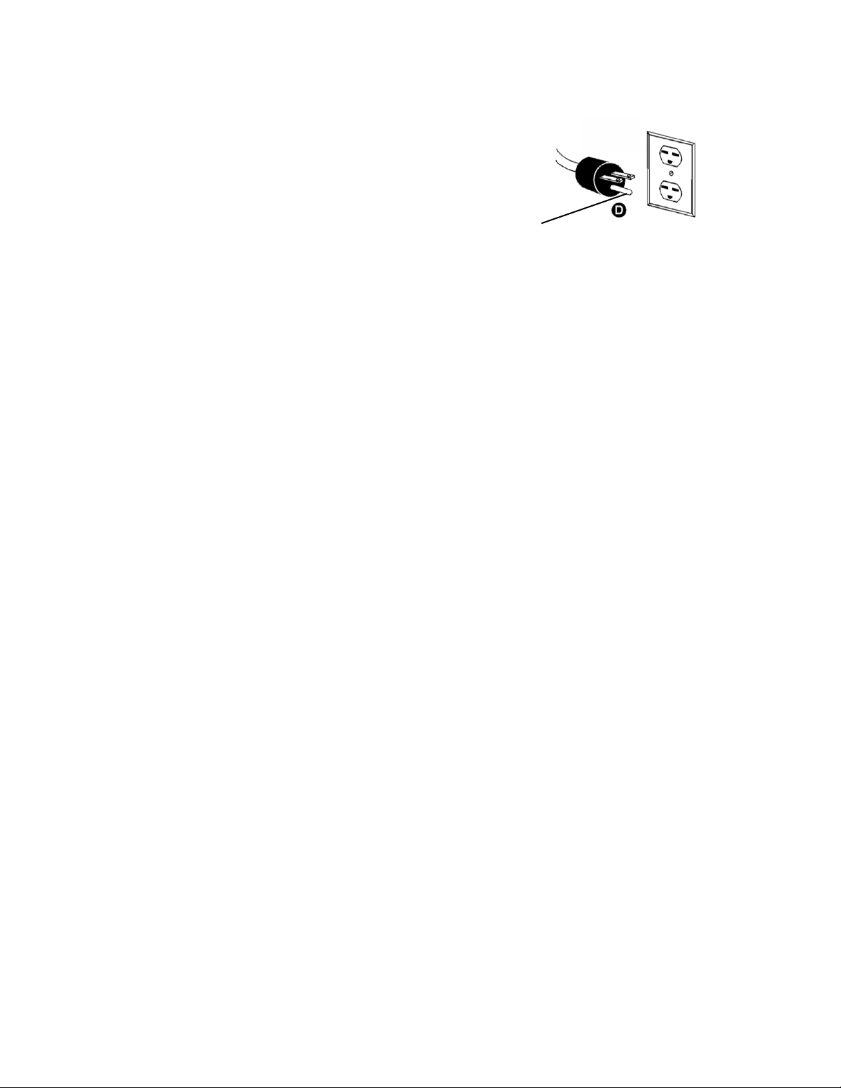
Grounding Pin
Depending on how this jointer was ordered it could be
made to operate at 220V single phase or 220V/440V
three phase. Be sure to confirm the correct operating
rating before connecting to power.
The jointer is supplied with a power cord, but no plug.
It may be hardwired to the service in accordance with
local electrical code. If a plug is used it must be
properly rated for the motor and match the outlet used.
Never use an adapter between plug and outlet and
always ground the machine.
To convert from 220V three phase to 440V three
phase new parts are required. Contact Oliver
Machinery for details.
With three phase power make sure the cutter head
rotation is in the proper direction.
All wiring and electrical connection must be done by a
qualified electrician and meet local electrical codes.
6
Page 9
Control Switch
!
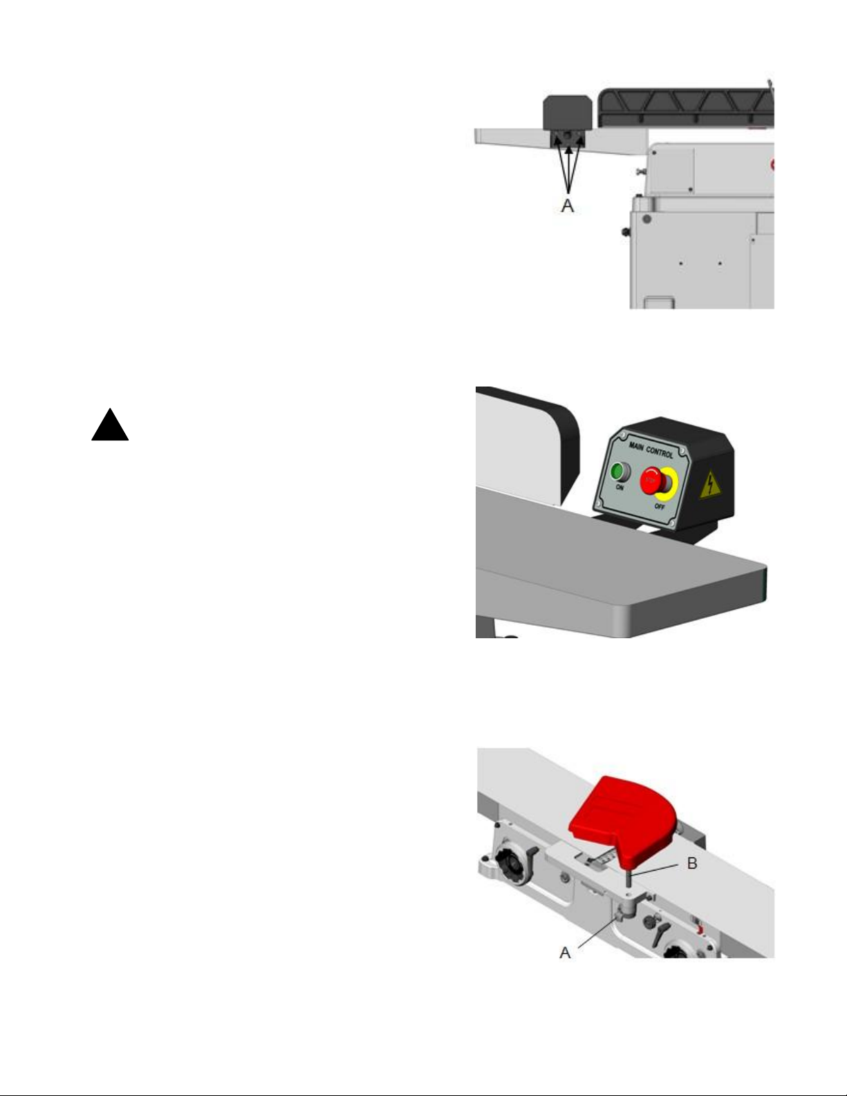
The control switch comes mounted to the infeed table
as shown Fig. 1
The control switch features an on and an off switch.
The off switch features a lock that must be twisted
clockwise to reset before the machine can be started.
This machine features magnetic motor controls. In
the event of power loss, the machine will not start
when power is restored until the on switch is pressed.
WARNING: Ensure that your workplace is
inaccessible to children by closing and locking all
entrances when you are away. NEVER allow
untrained visitors in workplace when assembling ,
adjusting or operating equipment.
Fig. 1
Cutterhead Guard Installing & Removal
1. Disconnect jointer from power source.
2. Turn knob (A) counterclockwise to create tension
on spring, and hold it there Fig 3.
3. Insert guard post (B) down through hole in front of
ledge.
4. Slightly turn set (A), if necessary, until the guard
seats itself, and the spring engages the slot at the
end of the guard post.
5. Check the guard for proper tension. If guard does
not spring back into place when pulled back from
cutterhead, remove guard and adjust spring
tension by repeating steps 1-3 until correct tension
is achieved. NEVER run the jointer without the
guard.
WARNING: Use the jointer guard for all
operations except rabbeting.
Fig. 2
Fig. 3
7
Page 10
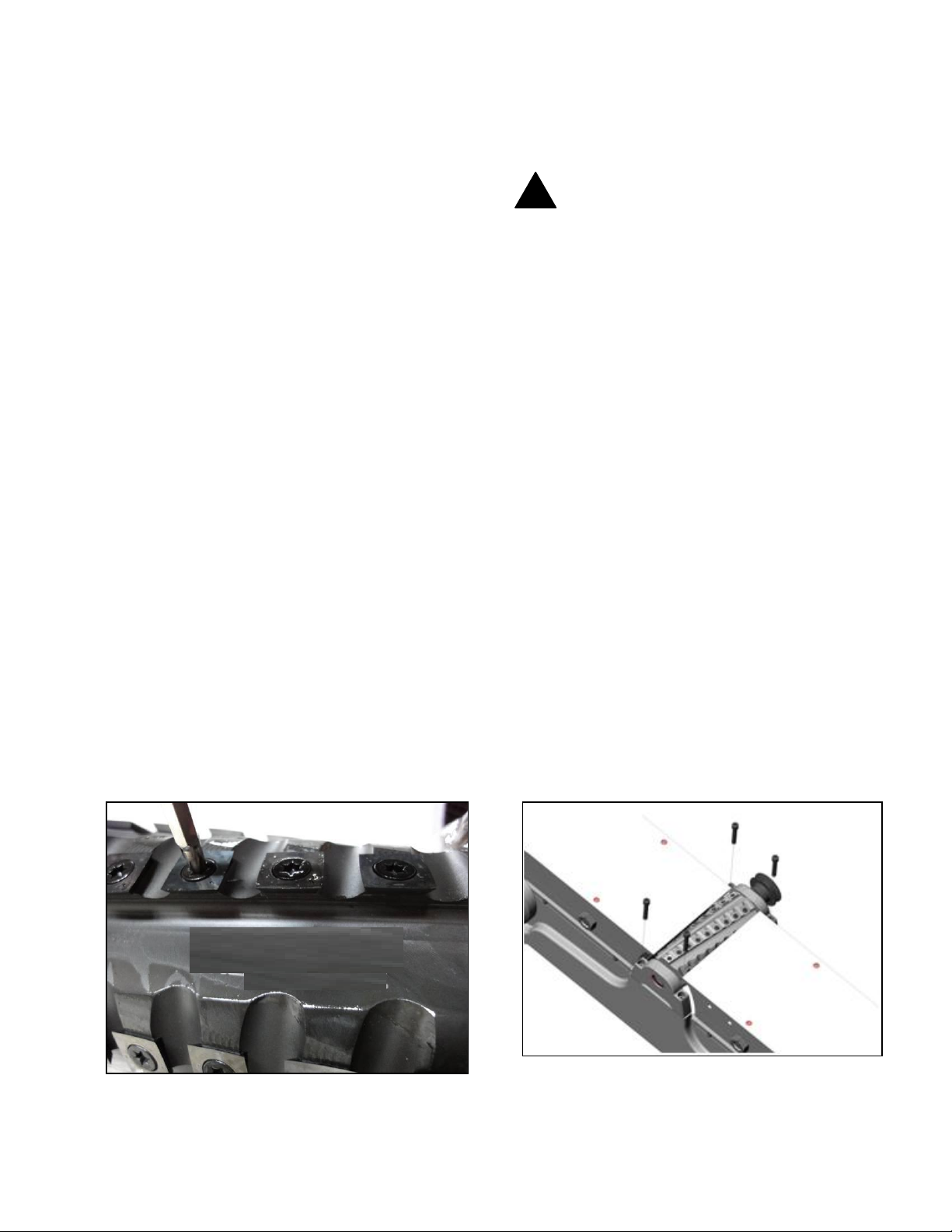
Helical Cutterhead
!
Knife inserts are dangerously
sharp. Use extreme caution when inspecting,
removing, or replacing knife inserts.
The knife inserts on the Jointer are four-sided.
When dull, simply remove each insert, rotate it 90°
for a fresh edge, and re-install it. No further
adjustment is necessary. Use the two provided torx
wrench to remove the knife insert screw. Use one
of the torx wrenches to help hold the cutterhead in
position, and the other to remove the screw. See
Fig. A. It is advisable to rotate all inserts at the
same time to maintain consistent cutting. However,
if one or more knife inserts develops a nick, rotate
only those inserts that are affected.
Each knife insert has an etched reference mark so
you can keep track of the rotations.
IMPORTANT: When removing or rotating inserts,
clean saw dust from the screw, the insert, and the
cutterhead platform. Dust accumulation between
these elements can prevent the insert from seating
properly, and may affect the quality of the cut.
Before installing each screw, lightly coat the screw
threads with machine oil and wipe off any excess.
Securely tighten each screw which holds the knife
inserts before operating the jointer!
Cutterhead Removal
If removal of the cutterhead is necessary, do the
following:
WARNING: Disconnect jointer from power
source.
1. Remove the entire fence assembly by releasing
lock handle and removing hex nuts. Lift the
fence off the machine.
2. Loosen the bolts connecting the motor to the
motor mount and remove the drive belt from
cutterhead pulley.
3. Lower both infeed and outfeed tables to expose
the cutterhead.
4. Remove the two bolts and spring washers which
secure the cutterhead to the base, as shown in
Fig. B.
5. Remove the cutterhead as sembly, with studs
attached, by lifting cutterhead straight up from
base. The belt pulley may be left on
cutterhead to assist in raising the cutterhead.
6. Remove pulley and both bearing housings with
attached studs from the cutterhead.
NOTE: You may wish to keep on hand an
extra cutterhead in order to maintain shop
productivity.
Make sure all knife insert screws are tightened
securely. Loose inserts can be propelled at high
speed from a rotating cutterhead, causing injury.
Fig. A
7. When mounting new cutterhead to base, make
sure the curved seats of the base are cleaned and
free of dust and grease.
Fig B
8
Page 11
Fence
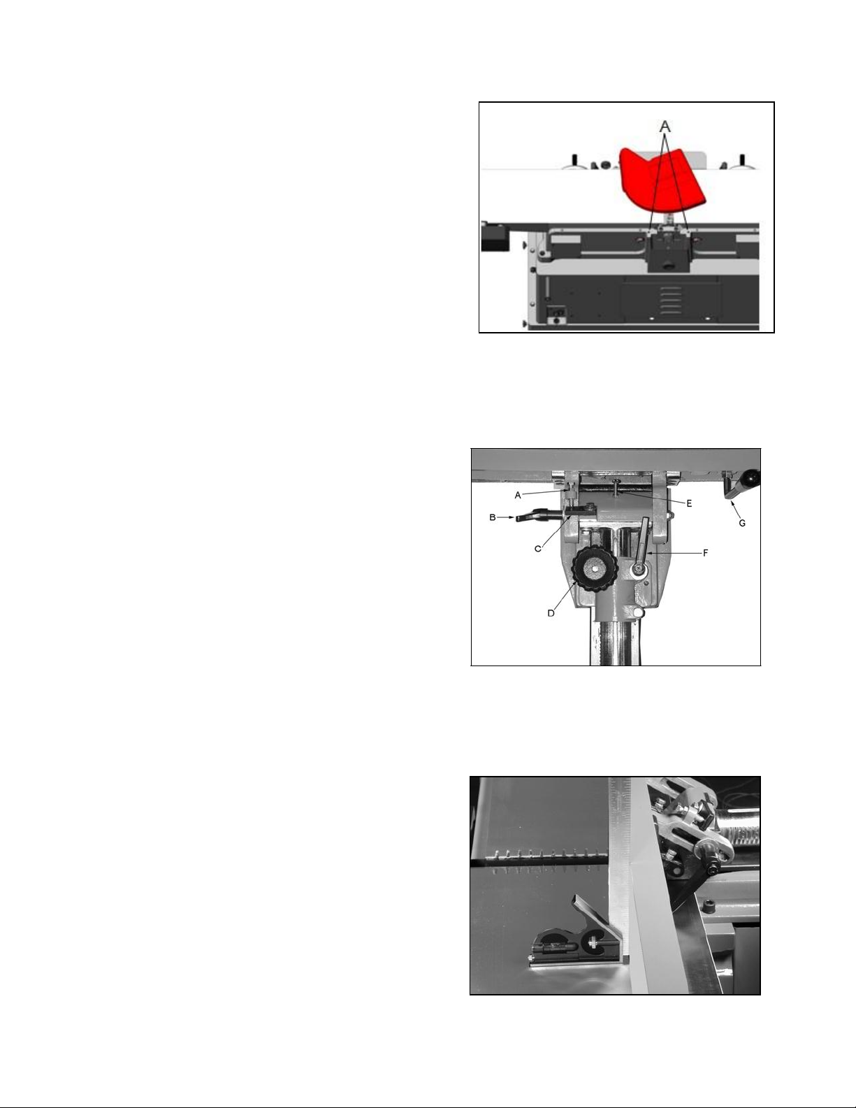
The fence is assembled and comes mounted
to the jointer. If it needs to be removed, take
off by removing the bolts as shown Fig, 4
The width adjustment handwheel (D, Fig. 5)
will need to be installed.
WARNING: Never make any adjustments to
the fence when the machine is running. All
machine adjustments should be made with
the power off or machine unplugged.
Fence Legend
The various adjustments, locks and handles
are shown in Fig.5.
A. 90 degree adjust bolt.
B. Angle lock handle.
C. 90 degree flip stop.
D. Width adjustment handwheel.
E. 45 degree adjust bolt.
F. Width lock handle.
G. Fence angle adjust handle.
Fig. 4
Adjustment of the 90 Degree Stop
1. Lay a square on the infeed table as shown
in Fig. 6
2. Loosen the angle lock handle (B, Fig. 5).
3. Ensure the 90 degree flip stop
(C, Fig. 6) is in the 90 degree position.
4. Loosen the jam nut on the 90 degree
adjusting bolt (A, Fig.6) and adjust the bolt
against the flip stop until the fence becomes
true with the square.
5. Tighten the jam nut while holding the bolt
in position.
Fence Operation
To tilt the fence, see Fig.5. Loosen angle
lock handle ‘B’, flip up the stop ‘C’, and tilt
the fence with the fence angle adjusting
handle ‘G’ to the desired angle. Use a
protractor or adjustable triangle to set the
angle. A 45 degree stop, ‘E’ is provided for
quick set-up at this angle.
To adjust the cutting width loosen the lock
handle ‘F’ and turn the width adjustment
handlwheel ‘D’ to move the fence toward
or away from the rabbeting ledge.
Fig. 5
Once any adjustments are made be sure
to lock them into place.
Fig. 6
9
Page 12
Hand Safety and Placement
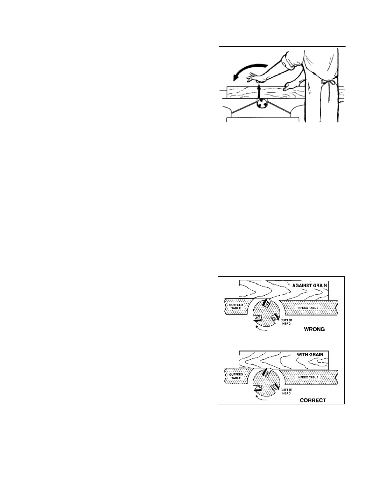
Never pass the hands directly over the cutter
knife. As one hand approaches the knives
remove it from the stock in an arc motion and
place it back on the stock in a position beyond
the cutter knife. See Fig 7.
When feeding the work piece, pressure is
applied not only toward the cutterhead but
against the fence and down to the table as well.
At the start of the cut, the left hand holds the
material down and toward the fence while the
right hand pushes toward the cutterhead. As
the material crosses the cutterhead the left
hand comes up and over as in Fig 7 to
continue the pressure but now on the outfeed
table. As the right hand approaches the
cutterhead it is time to move it up and over the
cutterhead in the same fashion as the left in
Fig 7 all the while continuing pressure as
stated above.
WARNING: Keep all guards in place. Keep hands
away from the cutterhead! Always use push stick
when possible.
Failure to comply may cause serious injury.
Fig. 7
Jointing
In order to craft a good woodworking project, it
is necessary to have a square piece of wood to
start with. The way to do this is with a jointer.
You need one straight edge and one flat face.
After you have these, you can plane to
thickness and rip to width and the resulting
piece will be square and true on all four sides.
At this point you can begin building your
project.
Direction of the Grain
To avoid tear out, always feed the material in
the direction of the grain. If the direction of the
grain changes half way through the board, try
taking lighter cuts at a slower feed rate. If the
results are still unsatisfactory, try turning the
material around and feeding the other way.
(Fig. 8)
Fig. 8
10
Page 13
Edging
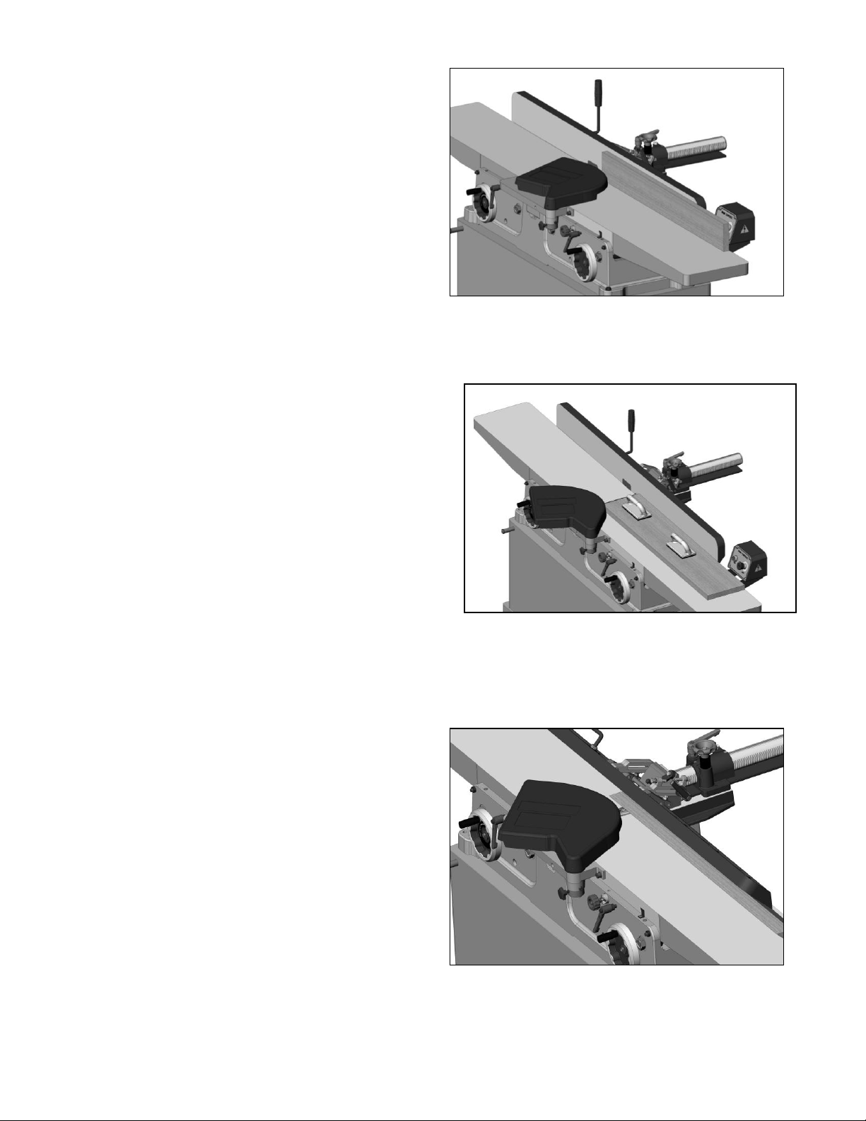
To give a good straight edge for gluing or
joining, set the fence square with the table.
Remove the least amount of material required
to obtain a straight edge. Hold the best face
of the piece firmly against the fence throughout
the feed. When finished you will have a perfect
starting point for your project. (Fig. 9)
Facing
Once you have a good edge it is time to
eliminate any warp or cup on the board. Keep
in mind the outfeed table is the reference point
and once the material is past the cutterhead,
downward pressure should be applied to the
outfeed table only. Putting downward pressure
on the board over the infeed table will bend any
cup or warp prior to hitting the cutterhead and
after the pressure is released, the cup will
spring back. At the same time try keeping a
constant feed rate in order to give a good
smooth cut with no burn marks
.
(Fig. 10)
Fig. 9
Beveling
For beveling (Fig 11), set the fence to the
desired angle using a protractor and lock into
place. Feed the material through pressing
firmly against the fence and tables. Several
passes may be necessary for the desired result.
Fig. 10
Fig. 11
11
Page 14
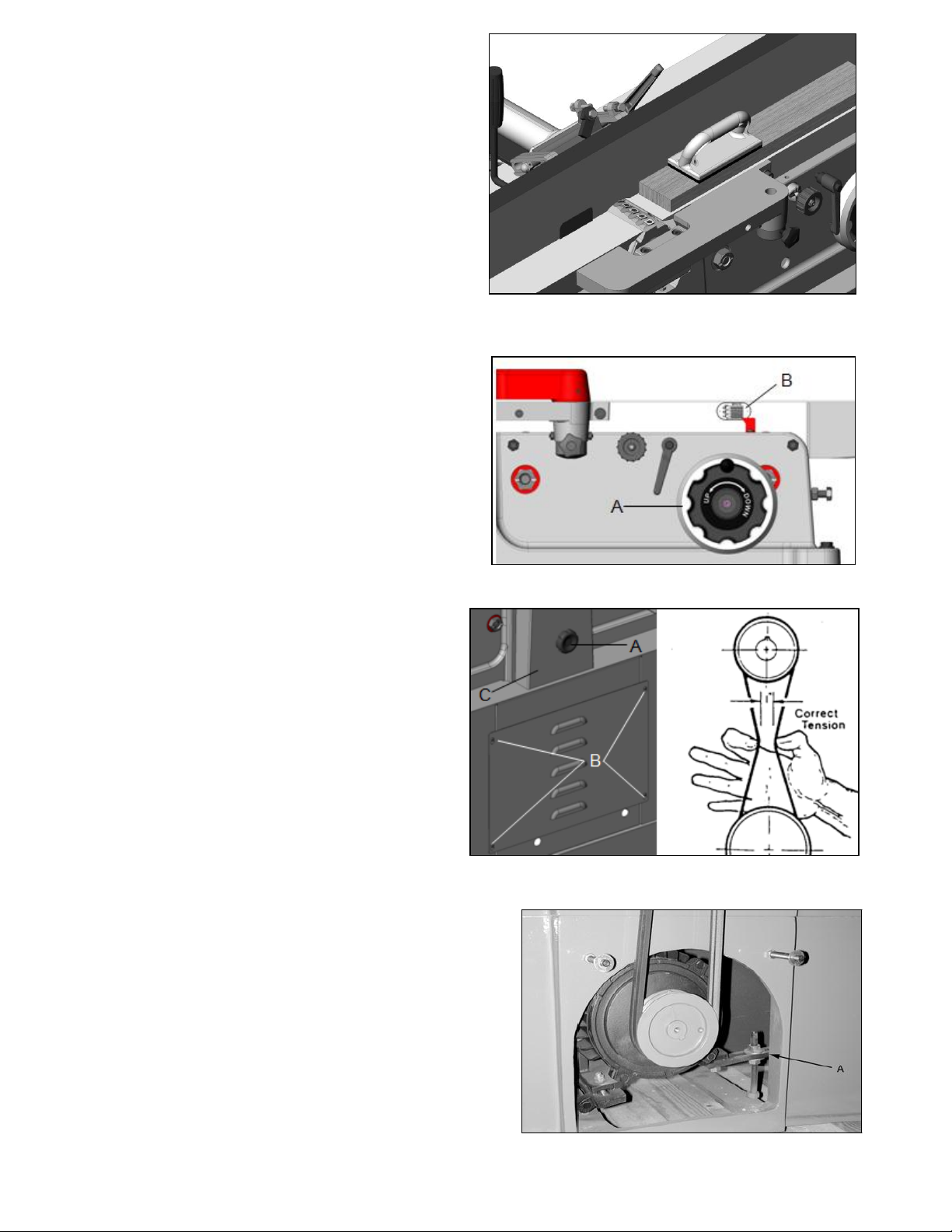
Rabbeting
1. Adjust the fence so that the distance
between the edge of the knife and the
fence is equal to the width of the desired
rabbet (Fig 12).
2. Lower the infeed table to the depth of the
rabbet required. If the rabbet is quite deep
it may be necessary to do it in increments.
WARNING :
the blade guard. Use extreme caution and
replace the guard after completion.
Rabbeting requires removal of
Adjusting the Infeed Table Height
The height of the infeed table with respect to
the cutting circle will determine the amount of
material to be removed from the work piece.
To raise or lower the table, turn the height
adjusting wheel (A, Fig 13) on the back of
the infeed table to the desired height indicated
by the guage (B, Fig 13).
Infeed Table Lock
The 4260 jointer is equipped with an infeed
table lock that will limit the maximum depth of
cut to 1/8” unless released by the operator.
The lock must be released during any infeed
table adjustment to prevent damage to the
raising mechanism.
Fig. 12
Fig. 13
Adjusting V-Belts
After the first 20 hours of operation it is
necessary to check the tension on of the Vbelts. To do this, loosen the knob A open the
pulley cover (C, Fig. 14). With medium finger
pressure the belt should push in approximately
½” about midway between the pulleys. If there
is too much play, remove the four screws (B,
Fig. 14) and take the cover off. Adjust the
tension by loosening the bottom jam nut on
the bracket (A, Figure 15) and then turn down
the top nut until the desired tension is
achieved.
12
Fig. 14
.
Fig. 15
Page 15
Lubrication
Periodically apply a lightgrease to the tables up/
down lead screw. As well, apply a light oil to the
dovetail ways from time to time to allow ease of
movement.
The cutterhead bearings are permanently
greased for life and do not require care.
Setting Table Coplanar
To achieve optimal results from your jointer, the
infeed and outfeed tables must be parallel front
to back and side to side, coplanar. If they are
not, the finished workpiece may have a slight
taper to it.
The tables have been properly aligned at the
factory and the results are on an inspection
sheet included with the new product. However,
during handling and normal use, the tables can
come out of adjustment. This alignment should
be checked periodically or when the finished
workpiece shows a taper.
The following steps should be followed to set the
tables coplanar. It is the same procedure to set
both infeed and outfeed tables. A steel straight
edge is needed to properly complete this
adjustment.
Disconnect the jointer from the power source. If
hardwired turn the breaker off at the service
panel.
Remove the cutter head guard. Be extremely
careful around the cutter inserts, they are very
sharp.
Slide the fence as far back as possible or
remove it from the machine.
Loosen the table locks on the front of the
machine.
Adjust the outfeed table above the cutter head.
Lock the outfeed table in this position.
Place the steel straight edge across the edge of
the outfeed table and extending over the infeed
table.
Raise the infeed table until it just comes in
contact with the steel straight edge. Lock the
infeed table in this position.
13
Page 16
The machinist straight edge should lie evenly
across the infeed and outfeed tables without a
gap between the straight edge and tables. Move
the straight edge across the tables and check for
gaps at any position from front to back.
If the steel straight edge does not lie evenly and
gaps are found one or both tables may need to be
adjusted to make the tables coplanar.
Both tables are adjusted in the same manner.
Adjust one table and then the other if needed.
Proceed as follows with the outfeed table first if
both need to be adjusted.
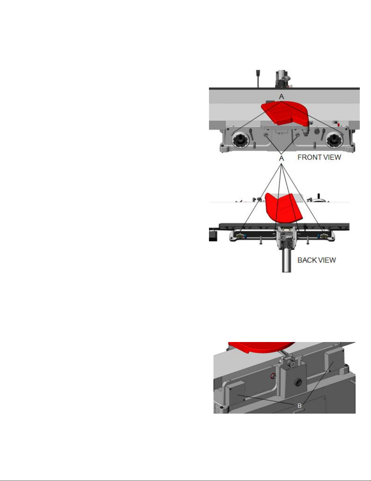
Each table has four cam adjusting nuts, two in the
front and two in the back (A, Fig. 16). One front
adjusting nut is located behind the table raising
handwheel and one back adjusting nut is located
inside covers B (Fig. 17).
Now that the four cam adjusting nuts are exposed
you will need to loosen the set screws before any
adjustment. Above each cam adjusting nut is a
plastic cap, pry out the cap and remove the set
screw below the cap.
With a 32mm wrench (not included) adjust the
cam nuts to raise or lower that portion of the table
as needed until the table coplanar is properly
aligned with no gaps between the straight edge
and tables. Repeat at each point until all are
aligned.
Retighten each set screw and replace the plastic
caps.
Replace the cover of back adjusting nut.
Adjust the outfeed table even with the cutter head
and the infeed table to the desired cutting depth.
Fig. 16
14
Fig. 17
Page 17
Basic Operations
Before m aking any c uts on t he s tock, m ake a f ew
practice cuts by r aising t he i nfeed t able to “ 0" a nd
with the power disconnected. In this manner you will
acquaint yourself with the feel of jointer operations.
SURFACING
Two handed
push block
Adjust depth of cut. It is better to make cuts of approximately 1/64 inch. This will enable you to hav e
better control over the material being surfaced. Make
several passes if necessary to obtain proper stock
removal.
Never surface pieces shorter than 12 inches or thinner than 3/8 inch without the use of a special work
holding fixture. Never surface pieces thinner than 3
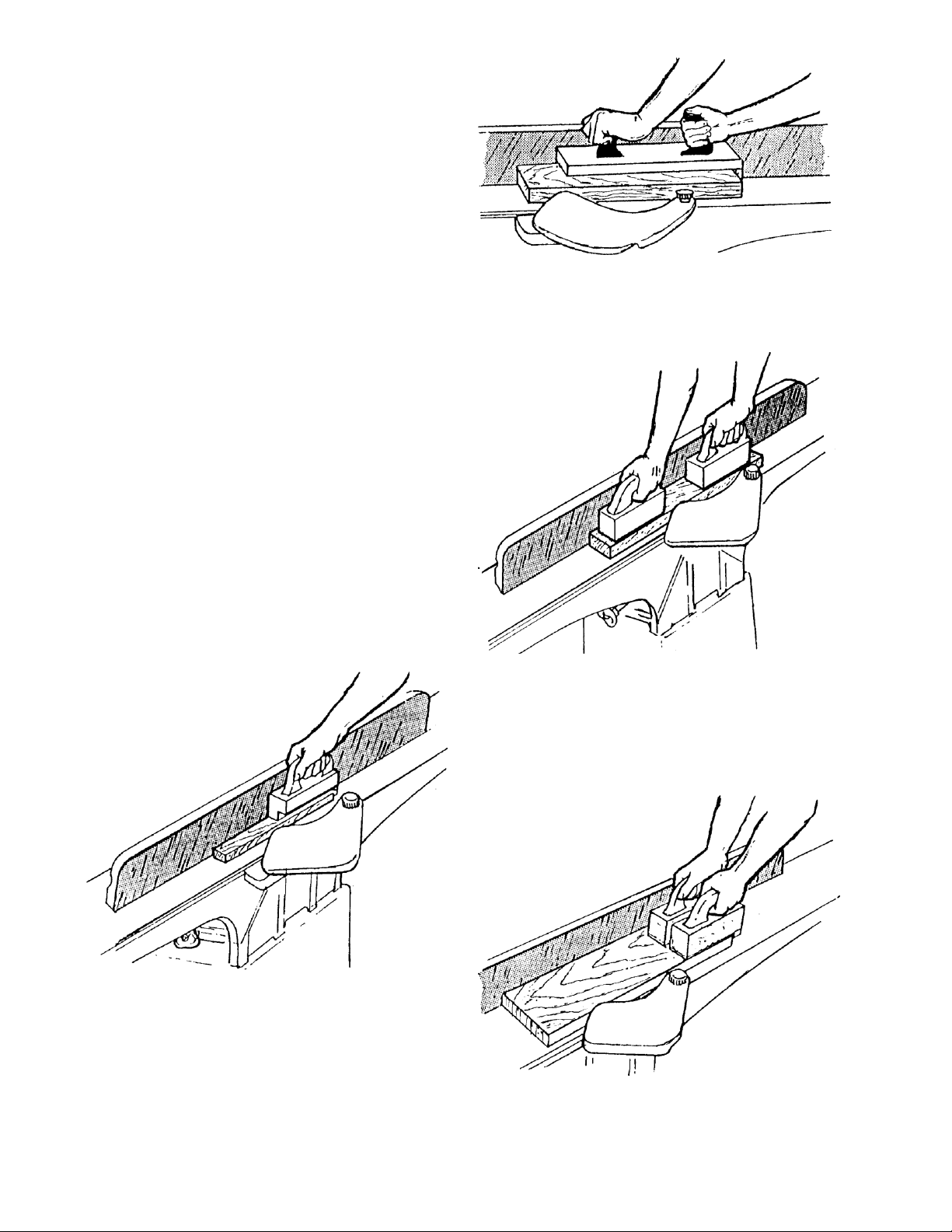
inches without the use of a push block. On stock 8"
to 12" long use a single two-handed push block (Fig.
18). On stock longer than 12 inches use two push
blocks ( Fig. 19). With narrow stock use the type
push block shown in Fig. 20. When surfacing short
stock over 4 inches wide, use two (2) push blocks to
guide material over cutterhead (Fig. 21).
Fig. 18
Two push
blocks for stock
longer than 12
inches
L-shaped push block
for narrow stock
Fig. 20
Two push blocks
with dowels
for short stock
over 4 inches wide
Fig. 19
Fig. 21
15
Page 18
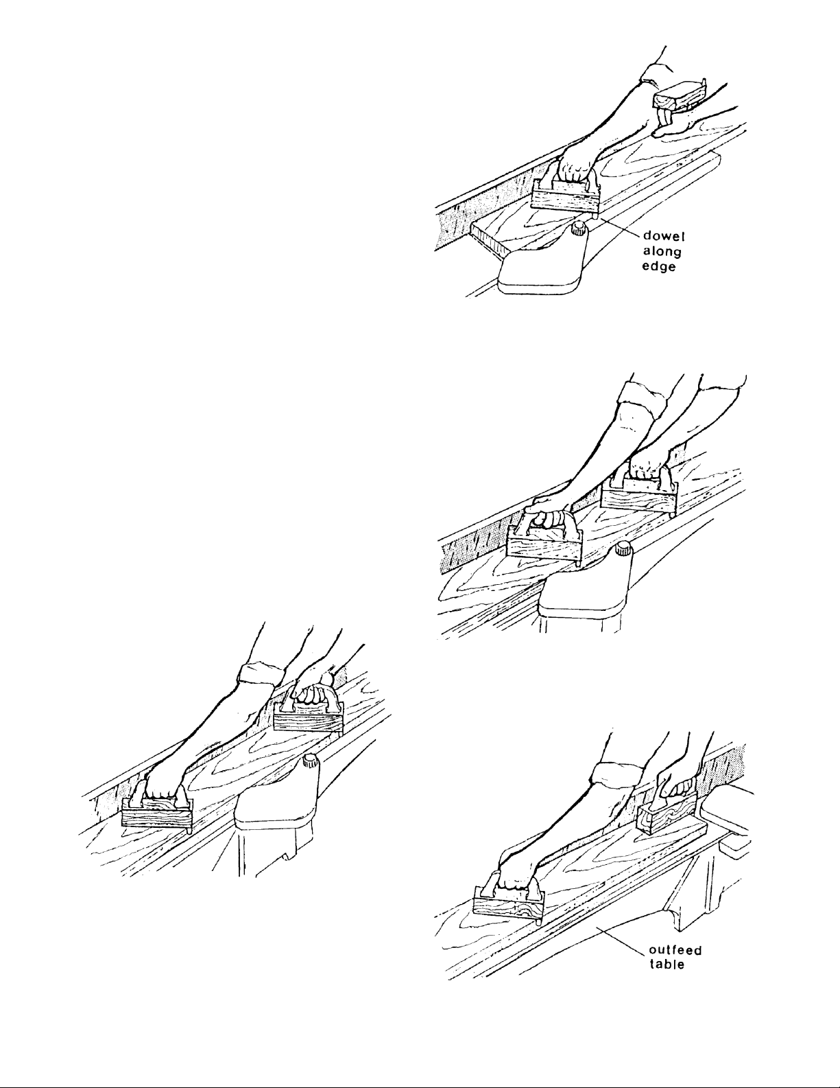
SURFACING: L ONG BOARDS
On outfeed
Side both hands
pull stock through
The use of p ush blocks w ill help to i nsure against
hands coming in contact with cutterhead in the event
of a kickback and as trailing end of board passes over
cutterhead.
When s urfacing l ong s tock, p lace push block near
the front of piece and start feeding wood with the right
hand until guard has opened and cut is started (Fig.
21). Place second push block near the rear of infeed
table and continue feeding stock using the hand over
hand method (Fig. 22). Before the left hand is in the
3 inch area of the cutterhead move it over to the outfeed
side (Fig. 23). As soon as possible follow with the
right hand over to the outfeed side and continue through
with cut (Fig. 24).
Begin by feeding stock with right hand and apply pressure to front of stock with push block.
When the stock is longer than twice the length of the
infeed and outfeed tables, another helper or support
table must be used to support the stock.
Left hand pushes
down toward fence
as right hand
starts feed
Fig. 21
Near cutter,
feed hand
over hand
Left hand is
moved to
outfeed
side
ig. Fig. 22
Fig. 23
Fig. 24
15
Page 19
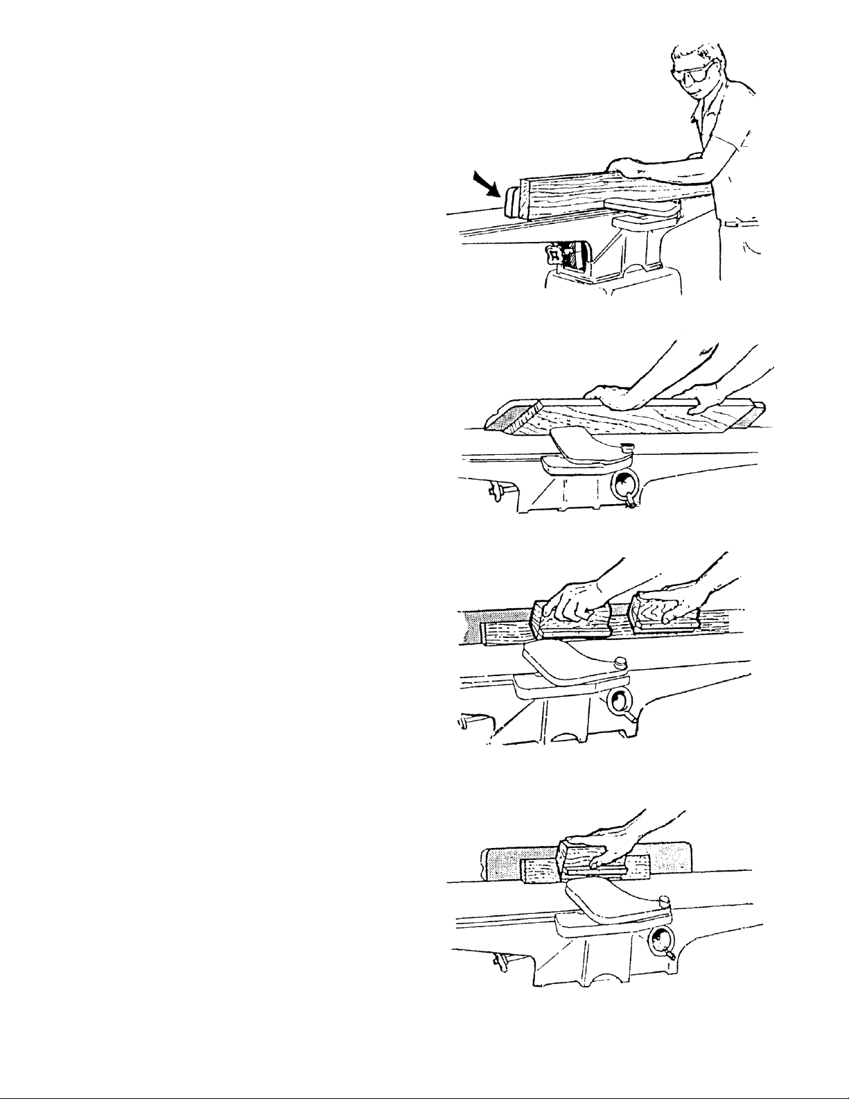
JOINTING (or EDGING)
Never edge a board that is less than 3 inches wide,
less t han 1 /4 i nch thick, o r 12 i nches l ong, w ithout
using a push block.
Move fence forward
to expose only amount
of cutterhead required
CAUTION: When workpiece is twice the
l ength of the jointer infeed or outfeed
table use an infeed or outfeed support .
Begin by feeding stock with right hand and apply pressure to front of stock with push block. When edging,
make cuts of approximately 1/16 inch for hardwood
and 1/8 inch for softwood.
When edging wood wider than 3 inches lap the finers over the top of the wood, extending them back
over the fence such that they will act as a stop for the
hands in the event of a kickback. Keep stock against
the fence (Fig. 25).
BEVELING
When beveling never make cut deeper than 1/16 inch.
Make certain material being beveled is over 12 inches
long, more than 1/4 inch thick and 1 inch wide.
Set fence to desired angle.
CAUTION: Although fence may be tilted in or
out for bevel cut, we
reasons the fence b e tilted in, if possible,
making a cradled cut (Fig. 26).
recommends for safety
Fig. 25
Fig. 26
For wood wider than 3 inches, hold with fingers close
together near the top of the stock, lapping over the
board and extending over the fence. When beveling
material less than 3 inches wide, use beveled push
blocks and apply pressure toward the fence. Keep
fingers near top of push block (Fig. 27).
When beveling short material use one bevel hold down
and apply pressure toward the fence. Keep thumb
above the ledge on hold down block (Fig.28).
CROSS GRAIN
NOTE: When beveling round four edges of a
workpiece, make cross grain cuts first. This will help
clean up any chipping or splintering when beveling
the end grain.
For long boards, follow the same hand-over-hand procedure used for surfacing long boards, (page 15).
Fig. 27
16
Fig. 28
Page 20
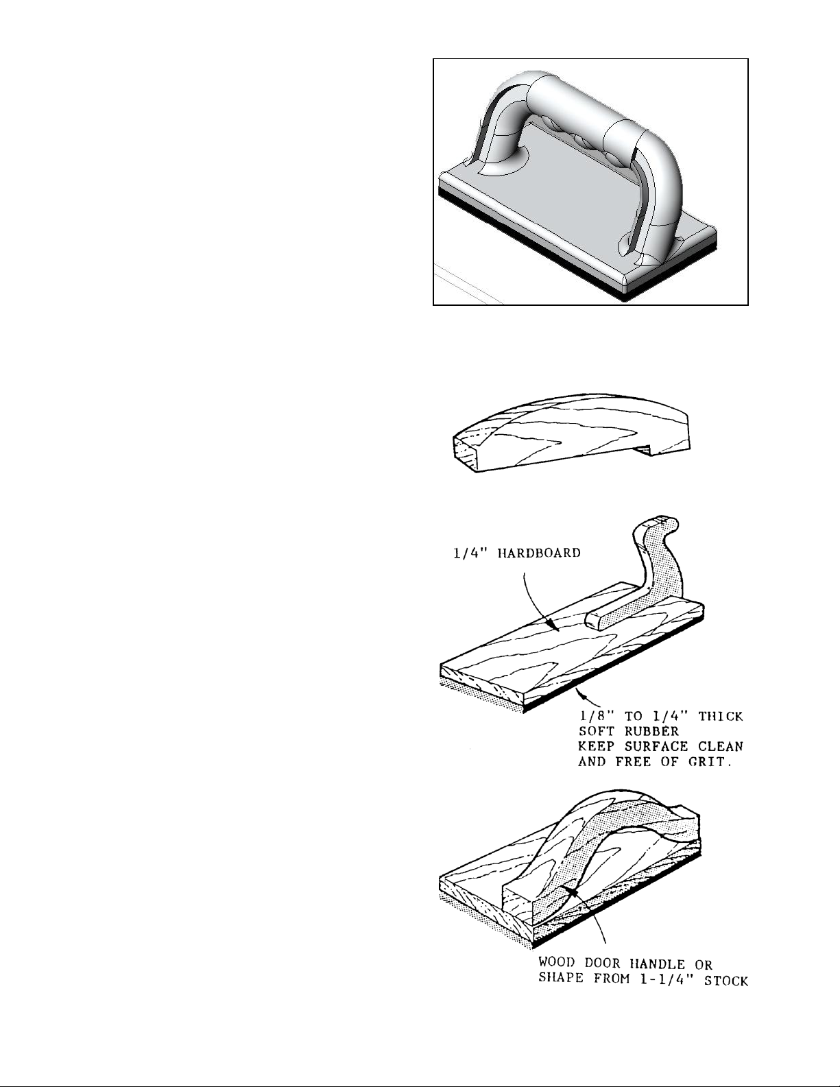
Push Blocks
Push blocks are simple, yet necessary tools to
assist the operator especially when jointing thin
or short stock. Illustrated in Figure 30 are three
types of push blocks commonly used in jointing.
Push blocks may be obtained commercially or
easily constructed.
NOTE: The Jointer is supplied with two push
block Figure 29 for feeding stock.
Fig. 29
17
Fig. 30
Page 21

Troubleshooting
Description of Symptoms
Possible Cause
Corrective Action
Machine will not start
1. Fuse blown or circuit
breaker tripped
2. Cord Damaged
3. Faulty switch
4. Not connected to power
source
5. No power to machine
6. Emergency stop button
pressed
1. Replace fuse or reset circuit
breaker
2. Have cord replaced
3. Replace switch
4. Check connection
5. Check voltage
6. Rotate emergency stop button
clockwise until it pops out
Cutterhead does not come up
to speed
1. Cable too light or too
long
2. Low current
3. Motor not wired for
correct voltage
1. Replace with adequate size cable
2. Contact local electric company
3. Refer to motor nameplate for
correct voltage
Unsatisfactory finish
Excessive vibration
1. Machine not level.
2. Damaged knives
3. Bad V-belts
4. Bent pulley
5. Improper motor
mounting
6. Loose hardware
1. Reposition on flat, level surface
2. Replace knives
3. Replace V-belts
4. Replace pulley
5. Check and adjust motor
6. Tighten hardware
Adjustments do not move
freely.
Sawdust and debris in
mechanisms
Clean and regrease
Finished stock is concave on
the end
Knife is higher than the
outfeed table
Adjust the outfeed table to the
highest point of the cutting circle
Back end of the stock is
thicker than the front end
Knife is higher that the
outfeed table
Adjust the outfeed table to the
highest point of the cutting circle
Finished stock is concave or
convex in the middle
Tables are not level
with each other.
Level one of the tables to the
other.
1. Dull Inserts
2. Gum or pitch on
inserts
18
1. Rotate or replace inserts
2. Rotate or replace inserts
Page 22
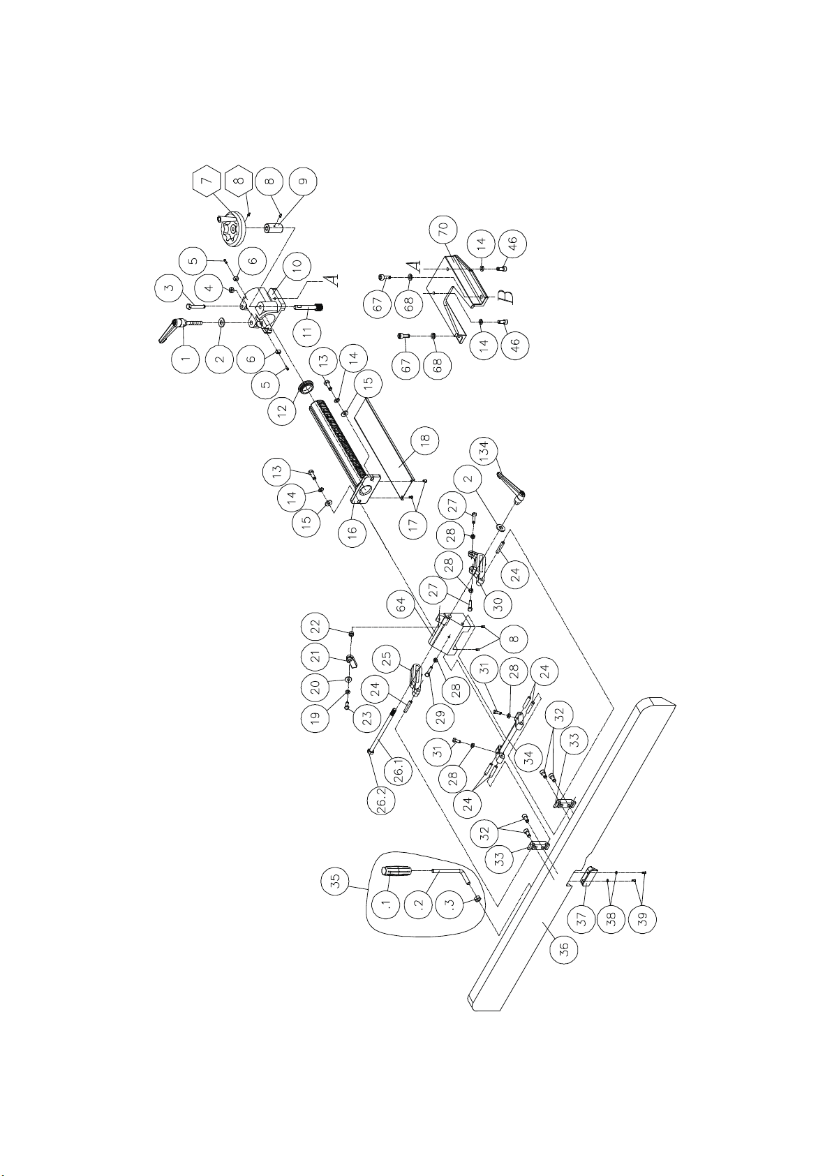
Fence
Page 23
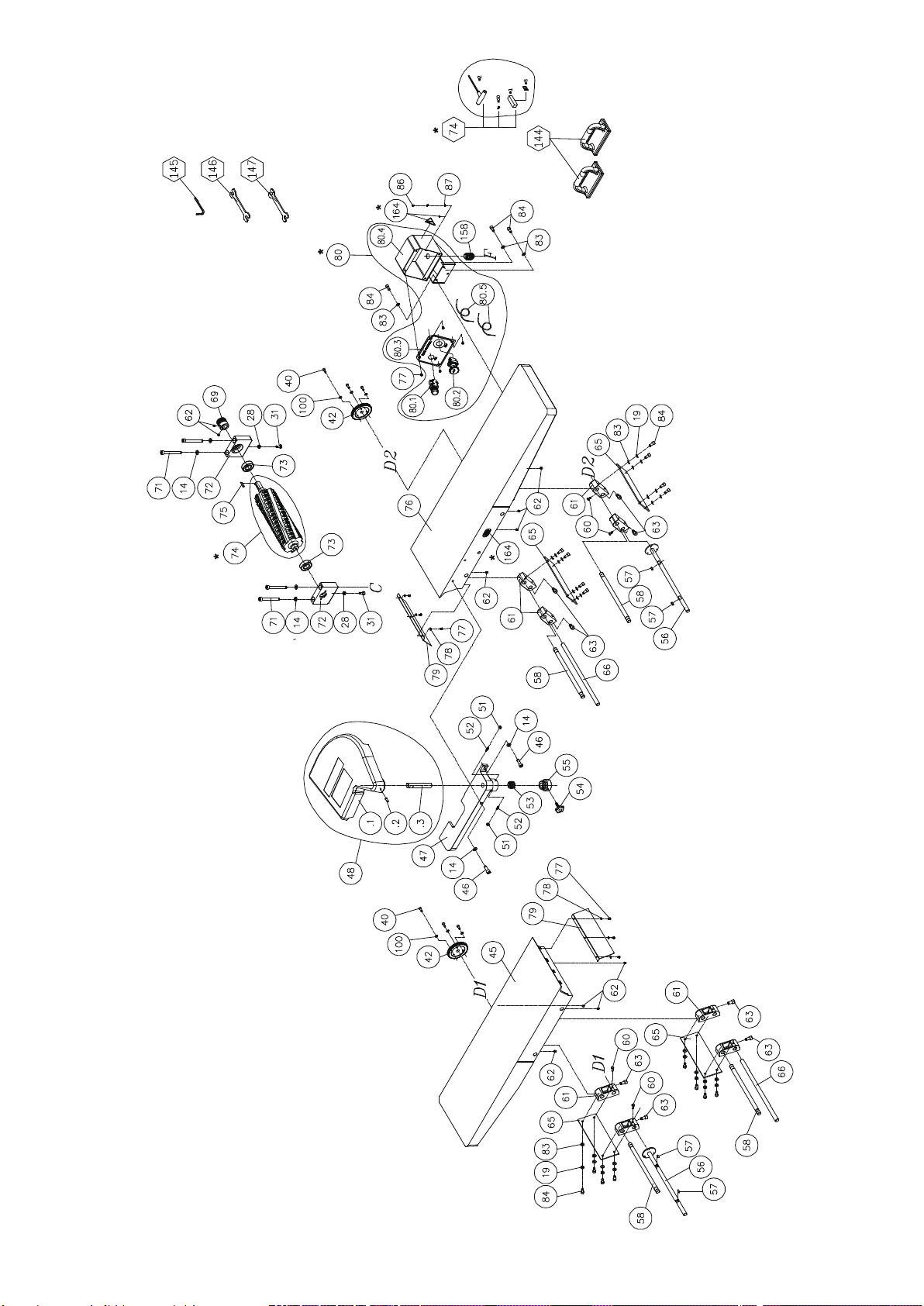
Tables
Page 24
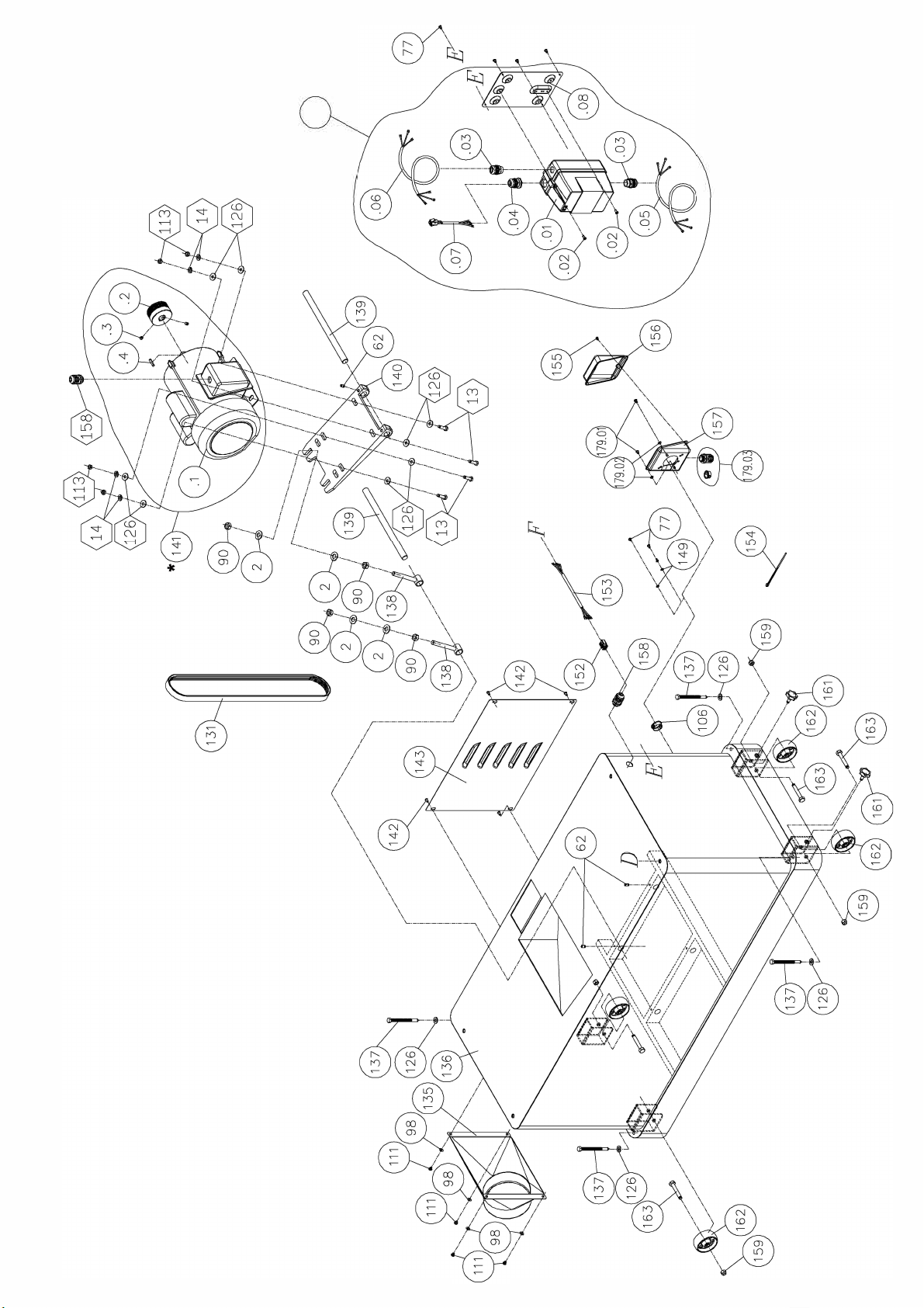
*
150
Cabinet
Page 25
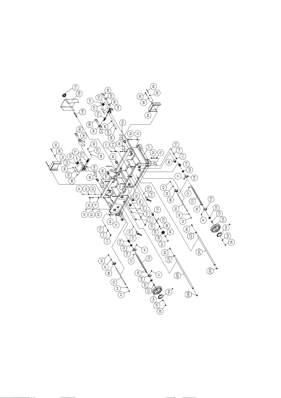
Base
Page 26

1
230262-000 Lock Handle 1
2
006002-096 Flat Washer 13.5*32*3.0t 6
3
000004-213
Hex Screw M10*1.5P*65 1
4
008007-200 Hex Nut M10*1.5P 1
5
000101-103
Cap Screw M4*0.7P*12 2
6
380832-901 Key 2
7
923595-000 Handwheel Assembly
1
8
000203-103 Set Screw M6*1.0P*10 4
9
380827-901 Sleeve 1
10
050902-000 Bracket 1
11
320297-000 Shaft 1
12
250702-615
Seal 1
13
000004-103 Hex Screw M10*1.5P*30 2
14
006307-100 Spring Washer
10.2*18.5 10
15
006001-071 Flat Washer 10*25*3.0t 6
16
381047-905 Rack
1
17
000801-101 Hex Screw M6*1.0P*10
2
18
172365-008 Guard 1
19
006305-100 Spring Washer 8.2*15.4 17
20
006001-056 Flat Washer 8.5*23*2.0t 1
21
380830-901 Positioning Block
1
22
380829-901 Sleeve 1
23
000003-205 Hex Screw M8*1.25P*25 1
24
360870-902 Shaft 6
25
050904-000 Sliding Bracket (Left) 1
26.1
230279-000 Shaft 1
26.2
380839-901 Clip 1
27
000003-209 Hex Screw M8*1.25P*45 2
28
008006-100 Hex Nut
M8*1.25P 9
29
000003-110 Hex Screw M8*1.25P*50 1
30
050903-000 Sliding Bracket (Right) 1
31
000003-204 Hex Screw M8*1.25P*20 4
32
000105-101 Cap Screw M10*1.5P*20 4
33
380828-902 Rear Clamp 2
34
070050-000 Link 1
35
922152-000 Handle Assembly 1
35.1
230381-000 Handle
1
35.2
380824-901 Bolt M12*1.75P 1
35.3
008009-200 Hex Nut M12*1.75P 1
36
051184-000 Fence 1
37
250462-615 Block 1
38
006002-001 Flat Washer 4.3*10*1.0t 2
39
000302-204 Pan Head Screw M4*0.7P*12
2
40
000103-705 Cap Screw M6*1.0P*15 2
41
002602-103 Cap Lock Screw M6*1.0P*16 4
42
381071-902 Gear 2
43
000103-103 Cap Screw M6*1.0P*12 4
44
006001-034 Flat Washer 6.7*16*2.0t 4
45
050654-000 Outfeed Table 1
46
000105-103 Cap Screw M10*1.5P*30
4
47
051183-000 Rabbet Ledge 1
48
922158-000 Cutterhead Guard Assembly 1
48.1
300023-000 Cutterhead Guard 1
48.2
000204-105 Set Screw M8*1.25P*20 1
48.3
360869-901 Shaft 1
49
006001-035 Flat Washer 6.7*19*1.0 1
50
361092-902 Rod 2
Parts List for 4260
Item Part No. Description Specification Qty
Page 27

Item Part No. Description Specification Qty
Parts List for 4260
51
009004-100 Hex Nut 1/4"-20NC 2
52
230275-000 Set Screw 2
53
280165-000
Spring 1
54
230273-000 Screw Bolt 1
55
380825-901
Shaft Collar 1
56
923491-000 Up/Down Shaft Assembly 2
57
012003-004 Key
5*5*15 4
58
360622-901 Shaft 4
59
012003-002 Key 5*5*10 2
60
048201-201 Hex Lock Screw M8*1.25P*20
4
61
050731-902 Link 8
62
001903-105
Set Lock Screw M8*1.25P*8 22
63
002604-101 Cap Lock Screw M10*1.5P*20 8
64
050907-000 Fence Bracket
1
65
173525-902 Positioning Plate 4
66
360625-901 Up/Down Shaft
2
67
000106-110 Cap Screw M12*1.75P*30
2
68
006308-100 Spring Washer 12.2*21.6 2
69
381072-902 Pulley 1
70
050905-000 Fence Support 1
71
000105-317 Cap Screw
M10*1.5P*90 4
72
051182-000 Bearing Bracket 2
73
030209-002 Ball Bearing 6205-2NSE 2
74
JK04-12 Cutterhead Assembly 1
040710-000 Torx Screwdriver T-25 2
038201-101 Torx Screw #10-32NF*1/2'' 84
P-15mm 4S Inserts Sold in Packs of 10 15*15*2.5t 84
75
012004-002 Pulley Key 6*6*30 1
76
050653-000 Infeed Table
1
77
000303-102 Pan Head Screw M5*0.8P*8 16
78
006001-009 Flat Washer 5.2*10*1.0t 6
79
173865-000 Dust Cover 2
80 950617-000 Control Box Assembly 1
80.1 490183-000 Lighted Starting Switch Green Light (220V) 1
80.2 490591-000 Emergency Stop Switch
KB2(RED STOP)+1b Connect(220V)(dia22)
1
80.3 573685-000 Switch Plate 1
80.4 173197-000 Control Box
1
80.5 471001-001 CSA Cable SJT18AWG*1C*85mm 2
83
006001-049 Flat Washer 8.5*16*2.0t 19
84
000104-105 Cap Screw M8*1.25P*18 19
86
000302-101 Pan Head Screw M4*0.7P*6 1
87
006501-100 Teethed Washer 4.3*8.5(BW-4) 1
88
300085-000 Block 2
90
008009-100 Hex Nut M12*1.75P 4
91
042502-000 Plastic Cap D9.5 8
92
000004-107 Hex Screw M10*1.5P*70 4
93
160059-000 Screw Bushing 8
94
173233-000 Gear Guard 2
95
000103-122 Cap Screw M6*1.0P*55 4
96
130010-903 Bushing 8
98
006001-032 Flat Washer 6.6*13*1.0t 17
99
000801-112 Phil. Head Hex Screw M6*1.0P*20 8
100
006303-100 Spring Washer 6.1*12.3 14
101
000203-101 Set Screw M6*1.0P*6 2
102
361012-902 Worm Shaft 2
103
361011-902 Up/Down Worm Shaft 2
104
051186-902 Bracket 2
Page 28

Item Part No. Description Specification Qty
Parts List for 4260
105
011003-102 Spring Pin 5*16 2
106
021801-000 Lock Ring NB-1722 1
108
380469-902
Bolt 1
109
171756-000 Belt Guard 1
110
230324-000
Knob 1
111
000304-103 Pan Head Screw M6*1.0P*12 5
112
173232-156 Indicator
1
113
008007-100 Hex Screw M10*1.5P 4
114
000205-102 Set Screw M10*1.5P*30 4
115
160025-000 Bushing 6
116
230343-000 Lock Handle 2
117
051158-000
Base 1
118
381190-902
Block
4
119
361090-902 Worm Shaft
2
120
030112-001 Ball Bearing 6002-2NSE 4
121
011003-104 Spring Pin
5*25 4
122
361010-902 Up/Down Shaft 2
123
160077-000 Bushing 2
124
922700-000 Handwheel Assembly Includes Folding Handle 2
125
006001-040 Flat Washer 8*30*3t 2
126
006001-076 Flat Washer
10.3*23*2.0t 4
127
009103-100 Lock Nut 1/4"-20NC
1
128
250461-615 Positioning Knob 1
129
280104-000 Spring 1
130
360465-901 Shaft 1
131
014343-000 Poly V-Belt 480J-9 1
132
011002-106 Spring Pin 4*25 1
133
130116-903 Cam 1
134
230279-000 Lock Handle
M6*1.0P*6 1
135
171471-000 Dust Chute 1
136
173230-000 Stand 1
137
003902-202 Bolt 3/8-16NC*4-1/2" 4
138
380249-901 Adjusting Shaft Assembly 2
139
360394-000 Shaft 2
140
050321-008 Motor Plate 1
141
Motor Assembly: Check the rating on existing motor to order replacement
141.1
EM3613T Baldor
3HP 1Ph 230V Only 1
141.1
L3606T Baldor 5HP 3Ph 230/460V 1
141.2
381083-902 Motor Pulley 1
141.3
001903-103 Set Screw M8*1.25P*8 2
141.4
Key 0.25" x 1.75" (Baldor Sourced) 1
142
000804-103 Phil. Head Hex Screw M5*0.8P*10 4
143
173231-000 Cover 1
144
250035-629 Push Blocks 2
145
Local Purchase Hex W rench 4mm 1
146
Local Purchase Open End W rench 11mm*13mm 1
147
Local Purchase Open End W rench 17mm*19mm 1
149
006502-100 Teethed Washer 5.3*10(BW-5) 2
150
JK04-02 Complete Switch Assembly 1
150
937742-000 Magnetic Switch Assembly 3HP 220V 1Ph or 5HP 220V 3PH Only 1
150.02
000303-104 Pan Head Screw M5*0.8P*12 2
150.03
021309-000 Strain Relief PGB16-14B (dia 9-14) 1
150.04
021310-000 Strain Relief PGB21-16B (dia 10 - 16) 2
150.05
474005-010 CSA Cable
SJT 10AWG*4C*1000mm (dia 16.5mm)
1
150.06
474005-011 CSA Cable
SJT 10AWG*4C*3300mm (dia 16.5mm)
1
150.07
950487-000 CSA Cable & Connector
2000W-06(Female)-CSA-SJT16AWG*5C
1
490697-000 Connector 2000W-06 1
Page 29

Item Part No. Description Specification Qty
Parts List for 4260
475002-006 CSA Cable SJT16AWG*5C*400mm 1
150.08
170977-901 Switch Board 1
152 490696-000 Connector 2000H-06 (Male) 1
153 475002-007
CSA Cable SJT16AWG*5C*1400mm 1
154 023311-000 Wire Clip ALC-110S 1
155
003303-102 Pan Head Screw
3/16"-24NC*1/4" 1
156
490124-000 Wiring Box Front Cover 1
157
490609-000 Wiring Box Rear Cover 1
158
021335-000 Strain Relief MG20A-14B (w/Nut)
2
159
009102-200 Lock Nut 3/8"-16NC 4
161
004001-101
Lock Knob 5/16"-18NC*3/4" 2
162
051068-000 Wheel 4
163
003005-206 Hex Screw
3/8"-16NC*2-1/2" 4
164
Label Advise content/location to order
165
361013-902 Rod
2
166
010010-000 S Ring STW-20
2
179.01
000303-103 Phippips Screw M5*0.8P*10
179.02
006001-009 Flat Washer 5.2*10*1.0t
179.03
021335-000 Strain Releif MG20A-14B (w/Nut)
180
180 Cap Screw
M6*1.0P*45 4
181
181 Bracket 2
Note: 440V 3Phase operation requires special components, contact Oliver Machinery.
Page 30

27
 Loading...