

Page 1
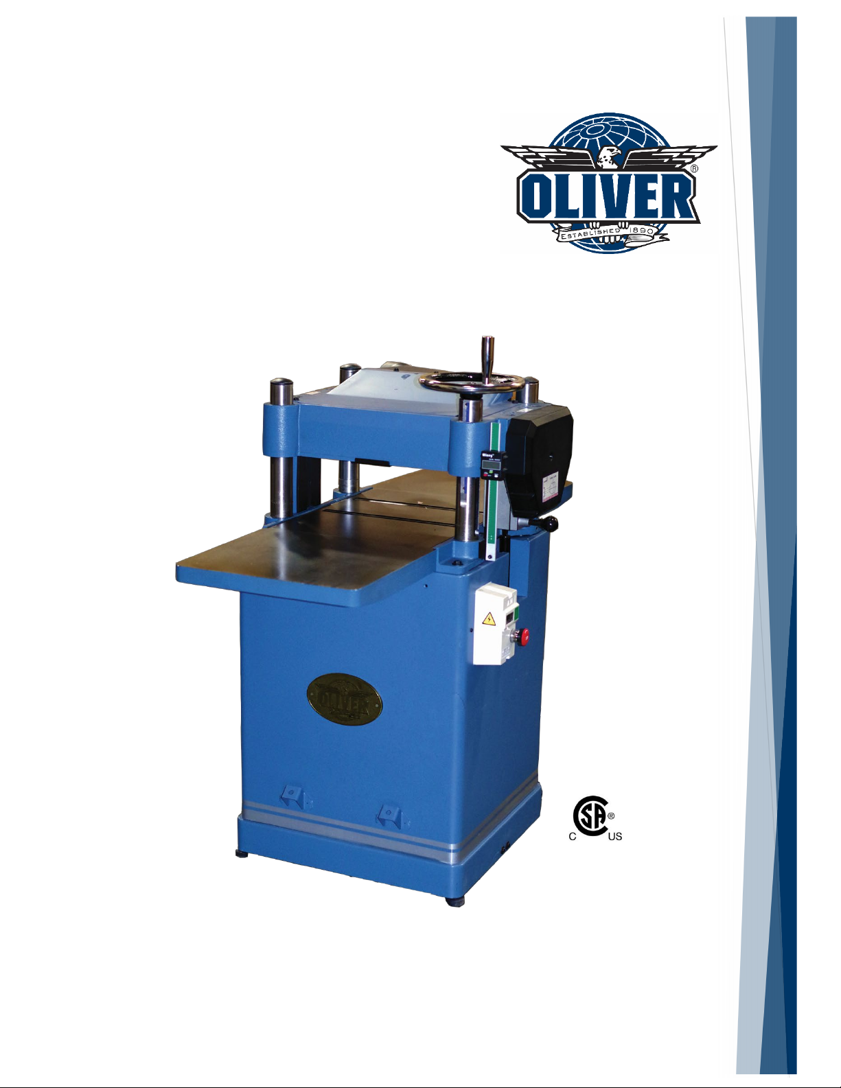
Planer
Model 10014
Owner’s Manual
For Models Manufactured Since 02/2020
175370
Oliver Machinery
WWW.OLIVERMACHINERY.NET
Stock Number: 10014.201
Manual Version: 1.0.0
1-800-559-5065
6902 S 194th St, Kent, WA 98032
Page 2

Page 3

READ AND UNDERSTAND ALL INSTRUCTIONS IN THIS MANUAL BEFORE
ATTEMPTING TO ASSEMBLE OR OPERATE THE MACHINE.
FOLLOW THE INSTUCTIONS AND THINK SAFETY!
THE OWNER OF THIS MACHINE IS SOLELY RESPONSIBLE FOR THE SAFETY OF ANYONE USING
THIS MACHINE. SUCH RESPONSIBILITY INCLUDES BUT NOT LIMITED TO:
• PROPER ASSEMBLY, OPERATION, INSPECTION, MAINTENANCE, AND RELOCATION OF
THE MACHINE.
• PROPER TRAINING FOR THE OPERATORS AND ENSURES THIS MANUAL IS AVAILABLE
AT ALL TIMES.
• USAGE AUTHORIZATION.
• USAGE OF SAFETY AND PROTECTION DEVICE.
OLIVER MACHINERY DISCLAIMS ANY LIABILITY FOR MACHINES THAT HAVE BEEN ALTERED OR
ABUSED. OLIVER MACHINERY RESERVES THE RIGHT TO EFFECT AT ANY TIME, WITHOUT
PRIOR NOTICE, THOSE ALTERATIONS TO PARTS, FITTINGS, AND ACCESSORY EQUIPMENT
WHICH THEY MAY DEEM NECESSARY FOR ANY REASON WHATSOEVER.
** SAVE THIS MANUAL FOR FUTURE REFERENCES. **
PROP 65 NOTICE
WARNING: Drilling, sawing, sanding or machining wood products can expose you to wood dust,
and/or other chemicals known to the State of California to cause cancer, birth defects or other
reproductive harm.
Some examples of these chemicals are:
• Lead from lead-based paints.
• Crystalline silica from bricks, cement and other masonry products.
• Arsenic and chromium from chemically-treated lumber.
Avoid inhaling wood dust and other harmful chemicals. Use a dust mask and/or other safety
devices for personal protection.
For more information go to http://www.P65Warnings.ca.gov/wood
Page 4

Table of Contents
Introduction ···················································6
Specifications ·················································7
Quick View ·················································7
Product Dimensions····································7
Shipment Info·············································7
Electricals ···················································7
Motor ························································8
Planer Capacity and Performance ···············8
Cutterhead and Headstock ··························8
Measurements ···········································8
Table ··························································9
Safety·························································9
Others ························································9
Identification ··············································· 10
Safety ·························································· 13
General Safety Guidelines ························· 13
Safety Guidelines Specific to Planer··········· 14
Electricals····················································· 16
Minimum Circuit Size Required for Model
10014 Planer ············································ 16
Assembly ················································· 22
Installing Height Adjustment Handwheel 23
Installing Dust Hood ································· 23
Installing Extension Tables ······················· 24
Dust Collection ········································· 26
Wiring and Grounding ······························ 26
Wiring Instructions ··································· 26
Break-in Period ········································· 26
Controls and Components ····························· 27
ON / OFF Switches ···································· 27
Cutterhead Height Adjustment ················· 27
Cutterhead Height Scale ··························· 27
Digital Readout (DRO) ······························· 28
Feed Rate Control ····································· 28
Components for Planing Wood ················· 29
Test Run ··················································· 30
Operation ···················································· 31
Step 1: Preparation ··································· 31
Step 2: Setting Depth of Cut and Feed Rate32
Step 3: Select Feed Direction ····················· 33
Step 4: Planing Wood to Desired Thickness33
Grounding ················································ 16
Electrical Wiring ······································· 16
Setup ··························································· 18
Shop Preparation······································ 18
Space Requirement ·································· 18
Load Limits ··············································· 18
Electricals ················································· 18
Lighting ····················································· 18
Safety Labels ············································· 18
Dust Collection ········································· 18
Receiving ·················································· 19
Unboxing ················································· 19
Inventory ················································· 20
Removing Machine from Crate ·················· 21
Cleaning ··················································· 22
Common Cutting Problems ······················· 35
Snipe ························································ 35
Chipping ··················································· 35
Indentation ·············································· 35
Fuzzy Grain ··············································· 35
Accessories ·················································· 36
Cutter Inserts ··········································· 36
Touchup Paint ·········································· 36
Maintenance ················································ 37
Maintenance Schedule ····························· 37
Lubrication Schedule ································ 37
Instructions for Maintenance and
Adjustments ············································ 39
Remove Planer Top Cover ························ 39
Adjust Chip Deflector Clearance ·············· 39
Page 5

Service Cutterhead and Rotate Cutter
Inserts ······················································· 40
Adjust Belt Tension ·································· 41
Adjust Table Chain Tension ······················ 42
Adjust Table Roller Height ························ 42
Adjust Cutterhead/Feed Roller Height
Offset························································ 43
Adjust Feed Roller Tension ······················· 46
Adjust Cutterhead Height Scale ··············· 47
Anti-Kickback Fingers Inspection·············· 47
Troubleshooting ··········································· 48
Wiring Diagram ··········································· 51
Parts List ······················································ 52
Table Assembly ········································ 52
Cabinet Assembly ····································· 53
Motor Mount Assembly ···························· 54
Headstock Assembly ································· 55
Gearbox Assembly ···································· 56
Cover and Dust Port Assembly ············· Error!
Bookmark not defined.
Maintenance Record ···································· 62
Notes ··························································· 63
Warranty and Service ··································· 64
Page 6
Introduction
Thank you for choosing Oliver! This manual contains important information on how to safely set up,
operate, and maintain this machine. Please take the time to read through this manual, and make sure
you understand all the instructions.
While this manual may provide tips on optimizing the result of your workpiece, the manual is not
intended as a substitute for formal woodworking training. If you need to know how to safely perform an
operation, please consult knowledgeable and qualified sources before proceeding further.
We made every effort to keep this manual up-to-date. Instructions, specifications, drawings, and
photographs in this manual should match the machine delivered. If you find any differences, or anything
that seems confusing in this manual, or some instructions are not available, please check our website for
an updated version:
WWW.OLIVERMACHINERY.NET/MANUALS
Alternatively, you can contact our Technical Support for help:
1-800-559-5065
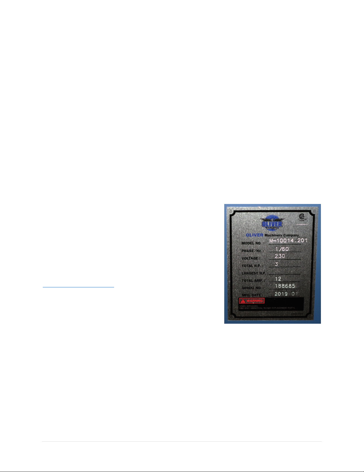
Before calling, please note down the manufacture date and serial
number of the machine. You can find the information on a
nameplate located on machine cabinet below the power switch.
This information is needed to provide proper technical support,
and to determine if an updated manual is available for your
machine.
Please let us know how well this manual serves you. If you have
any suggestions, please call the number above or email us at:
We love to hear from our customers and make improvements.
6 | Page Oliver Machinery 10014 Planer
Page 7

Specifications
Quick View
Model
10014 Planer
Stock Number
10014.201
Motor
TEFC Induction Motor
3HP, 230V, 1Ph
Max. Stock Width
15”
Max Depth of Cut
1/8” (Full width)
3/16" (Stock less than 8” wide)
Dimensions
47-1/2”(L) x 29”(W) x 47”(H)
Footprint
21”(L) x 22”(W)
Fully Assembled Weight
401 lbs.
Warranty
1 Year (Motor and electronics)
2 Years (All other parts)
Product Dimensions
Width x Depth x Height (Fully Assembled)
47-1/2”(L) x 29”(W) x 47”(H)
Footprint
21” (L) x 22”(W)
Fully Assembled Weight
401 lbs.
Shipment Info
Type
Wood Crate with Pallet Base
Content
Planer with Included Accessories
Dimensions
32 (L) x 30”(W) x 49-1/2”(H)
Weight
470 lbs.
Approximate Setup Time
60 minutes
Must Ship Upright
YES
Stackable
NO
Electricals
Power Requirement
230V, 1Ph, 60Hz
Full Load Current Rating
12A
Recommended circuit size
20A
Power Switch Type
Magnetic switch with overload protection.
Connection Type
7’ 14 AWG Cord included.
Overload Protection
Equipped
Electrical hookups required.
10014 Planer OLIVERMACHINERY.NET 7 | Page
Page 8

Motor
Motor Type
TEFC Induction Motor
Horsepower
3HP
Speed
3450 RPM
Efficiency / Power Factor
75% / 98%
Power Transfer Mechanism
Poly V-belt and pulleys
Bearing type
Permanently sealed ball bearing
Planer Capacity and Performance
Maximum Stock Width
15”
Maximum Depth of Cut
3/16" (Stock less than 6” wide)
1/8”(Full Width)
Maximum Stock Thickness
6”
Minimum Stock Thickness
3/16"
Minimum Stock Length
6”
Feed Rate
16/20 FPM
Cutterhead and Headstock
Cutterhead Type
Helical
Cutterhead Diameter
2-5/8”
Cutterhead Speed
5000 RPM
Number of Cutter Inserts
52
Number of Rows of Cutter Inserts
4
Cutter Insert Type
Four-sided, indexable German made carbide
Cutter Insert Diameters
15mm x 15mm x 2.5mm
Cutter Blade Angle
30 degree
Cutter Insert Screw Tensioning Torque
50-55 lbs.-inch
Infeed Roller Type
Serrated steel
Outfeed Roller Type
Smooth steel
Headstock Height Change Per Each Turn of
Handwheel
Approx. 0.6” / 1.5mm
Measurements
Measurement Units
Inch/mm
Measurement Devices
Wixey Digital Readout
Resolution
1/32”/0.002”/0.05mm
Accuracy
+/- 1/250”/0.004”/0.1mm
Backup Measurement Device
Standard headstock height scale installed.
8 | Page Oliver Machinery 10014 Planer
Page 9

Table
Table Dimensions
47-1/2” x 15”
Table Height Above Ground
30-1/4”
Material
Precision ground cast iron
Bed Roller
Two
Extension Table Weight
21 lbs.
Safety
Number of Dust Ports
1
Dust Port Size
4”
Minimum CFM Required
600 CFM
Sound Rating @ 2’ distance
85 dB
Others
Serial Number Location
On machine cabinet below the safety label.
Spare Parts Included
10 Cutter inserts and compatible torx screws.
Certification
CSA 175370
Country of Origin
Taiwan
(With infeed/outfeed table)
19-1/2” x 15”
(Without infeed/outfeed table)
10014 Planer OLIVERMACHINERY.NET 9 | Page
Page 10
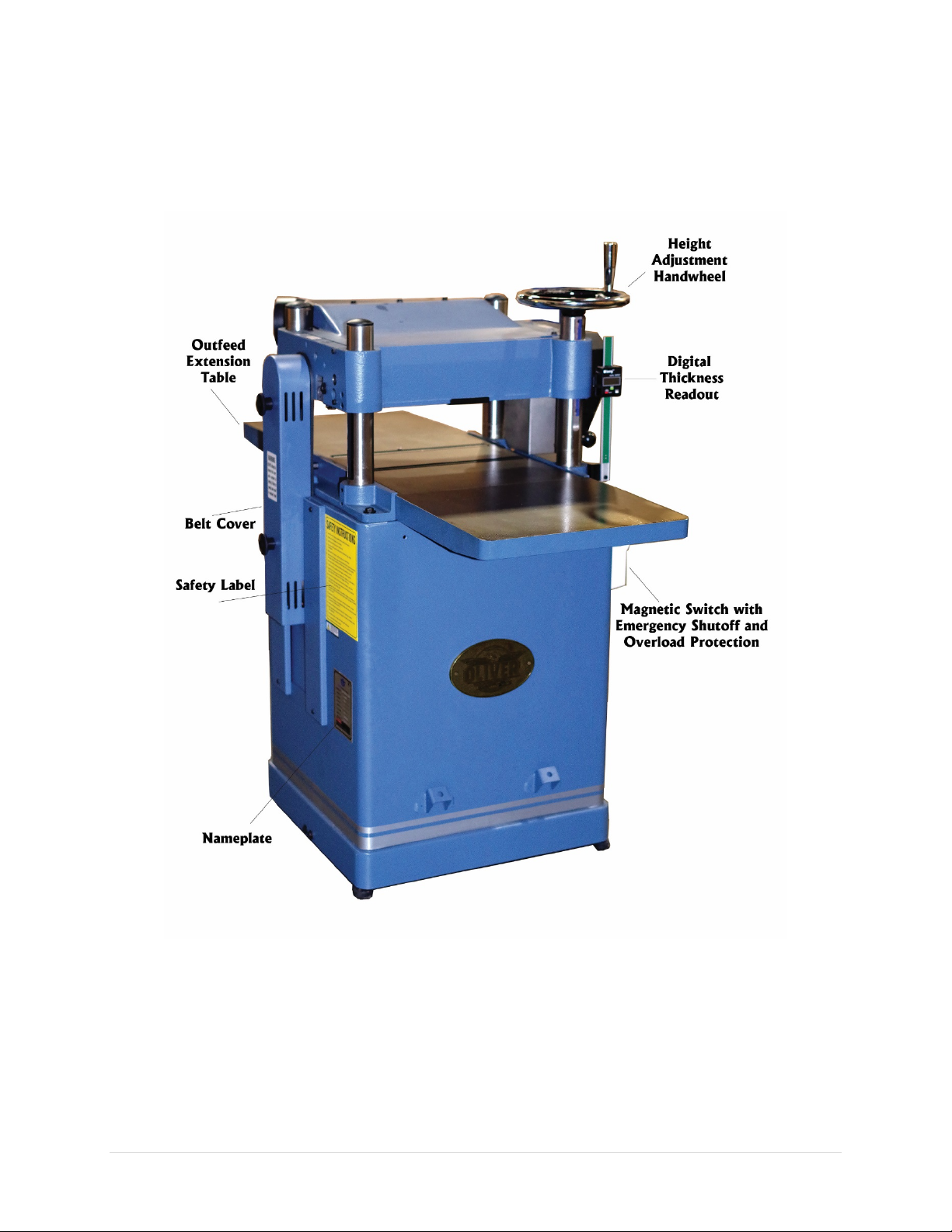
Identification
10 | Page Oliver Machinery 10014 Planer
Page 11
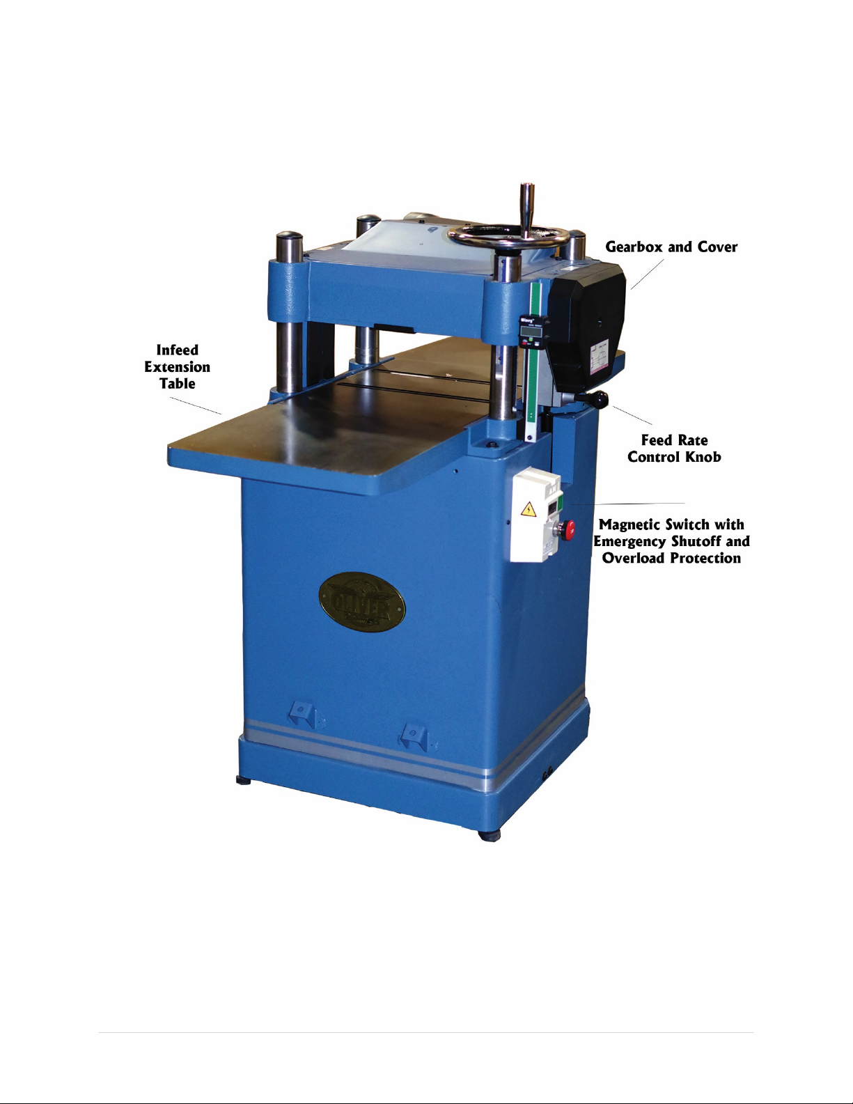
10014 Planer OLIVERMACHINERY.NET 11 | Page
Page 12
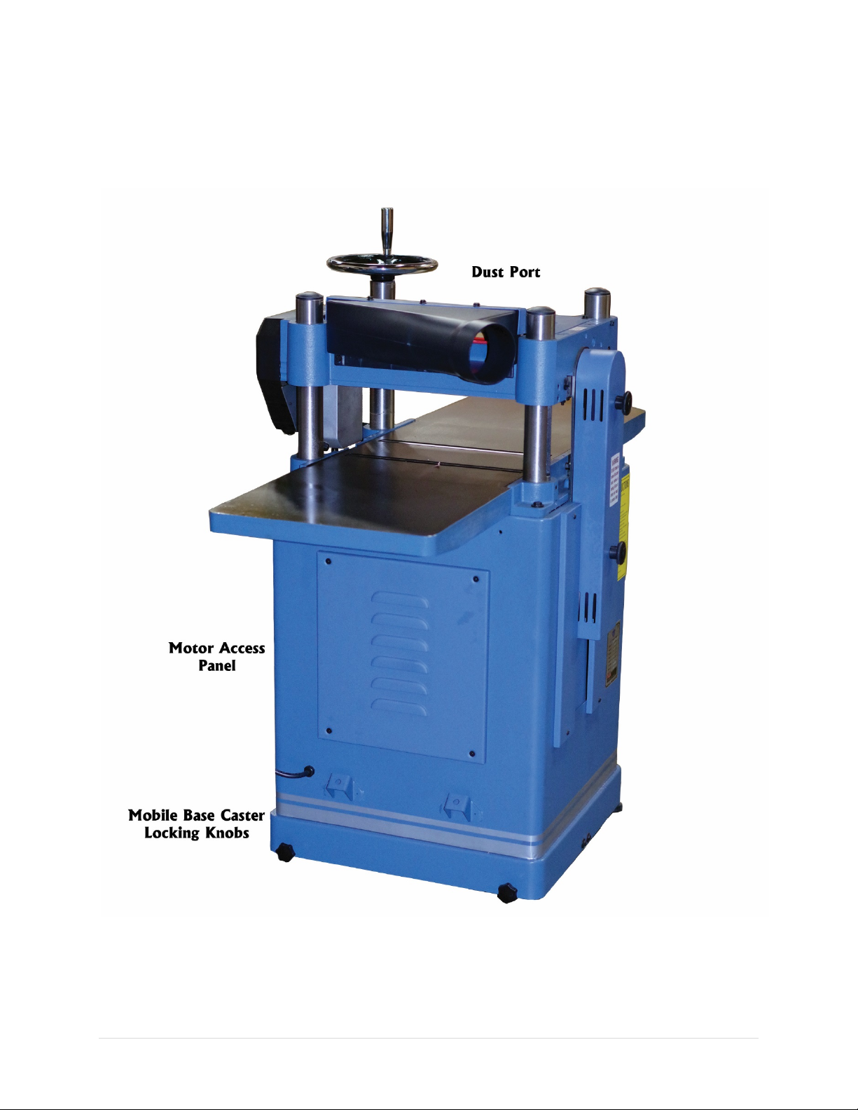
12 | Page Oliver Machinery 10014 Planer
Page 13

This indicate an imminent hazardous situation which, if not avoided, WILL cause
This means if the warning is not taken seriously, it CAN cause death or serious
Safety
Oliver Machinery has made every attempt to provide a safe, reliable, easy-to-use piece of machinery.
Safety, however, is ultimately depending on the individual machine operator. Before operating this
machine, please become familiar with the following safety labels and guidelines.
DANGER
WARNING
CAUTION
death or serious injury.
injury.
This mean if the precaution is not taken, it MAY cause minor or moderate injury.
IMPORTANT This is a tip about proper operation of the machine to avoid machine damage.
General Safety Guidelines
1. FAMILIARIZE yourself with all safety instructions found in this manual. Know the limitations and
hazards associated with this machine. Do not operate / service this machine until you are properly
trained.
2. ELECTRICAL GROUNDING, when done properly, reduce the risk of electrocution, shocks and fire.
Make certain that the machine frame is electrically grounded and that a ground lead is included in
the incoming electrical service. In cases where a cord and a plug are used, make certain that the
grounding plug connects to a suitable ground. Follow the grounding procedure indicated in the
electrical code of your area.
3. DISCONNECT the machine from power before performing any service, maintenance, or adjustments.
A machine under repair should be RED TAGGED to show it should not be used until the repair is
complete.
4. EYE PROTECTION: Always wear an approved safety face shield, goggles, or glasses that complies
with ANSI Z87.1 and CSA Z94.3 standards. Common eyeglasses are not safety glasses, and may not
provide adequate protection.
5. EAR PROTECTION: Use hearing protective devices where the noise exceeds the level of exposure
allowed in Section 1910.95 of the OSHA Regulations. When in doubt, use it.
6. OTHER PERSONAL PROTECTION: Before operating the machine, remove tie, rings, watch and other
jewelry. Roll up sleeves above the elbows. Remove all loose outer clothing and confine long hair.
Protective type footwear should be used. Do not wear gloves unless it is instructed to perform
particular step(s) in the manual.
7. GUARDS: Keep the machine guards in place for all applicable operations. If any guards are removed
for maintenance, DO NOT OPERATE the machine until the guards are reinstalled. Check clearance
between the guards and the cutter before starting the machine.
8. WORKPLACE SAFETY: Keep the floor around the machine clean. Scrap material, saw dust, oil and
other liquids increase the risk of tripping or slipping. Be sure to clean up the table before starting the
machine. Make certain the work area is well lighted and that a proper exhaust system is used to
10014 Planer OLIVERMACHINERY.NET 13 | Page
Page 14

minimize dust. Use anti-skid floor strips on the floor area where the operator normally stands and
mark off machine work area. Provide adequate work space around the machine.
9. ACCESS CONTROL should be enforced so only trained personnel can access the work area and
operate the machine. Use childproof power switch when applicable.
10. STAY ALERT at all times. Do not operate this machine while under the influence of drugs/alcohol, or
when not feeling well.
11. REPLACEMENT PARTS: Use only genuine Oliver Machinery replacement parts and accessories
recommended for this machine. Generic parts made by other manufacturers may create a safety
hazard, and WILL void the factory warranty and other guarantees.
12. PROPER USE: Do not use this machine for other than its intended use. If used for other purposes,
Oliver disclaims any real or implied warranty and holds itself harmless for any injury or damage
which may result from that use.
Safety Guidelines Specific to Planer
Before Work Begin:
1. USE ONLY NATURAL, SOLID WOOD. Do not plane any material such as plywood, MDF, OSB,
laminate or anything that can disintegrate during operation. Do not plane treated lumber or
anything that contains harmful chemicals, as this will spread wood dusts that contain such harmful
chemicals. Do not attempt to plane workpiece with loose knots or with any other foreign materials.
2. CHECK CUTTER INSERTS: Make sure cutter inserts are sharp, clean, and free from damages. Forcing
dull/damaged cutter inserts to work invites accidents, and lowers the quality of the finish. Use
recommended amount of torque to securely fasten all inserts onto the cutterhead.
3. SERVICING CUTTER INSERTS: Wear heavy duty leather clothes to protect your hands when installing
new cutter inserts or rotating the existing ones. Ensure the cutterhead is thoroughly clean before
installing the insert. Debris between the cutter insert and the platform can create uneven pressure,
causing the insert to break, and body injuries may occur.
4. SUPPORT LONG WORKPIECE with auxiliary stock feeding rollers/tables. This will help avoiding
injuries and improve the quality of finish.
14 | Page Oliver Machinery 10014 Planer
Page 15

When Planning:
1. DUST COLLECTION SYSTEM is required for this planer. Please make sure the system is on and
provide enough suction before operation begins.
2. KICKBACK happens when a workpiece is ejected, usually towards the infeed side of the planer,
during the operation. This can cause serious injuries or even death. This planner is equipped with
metal anti-kickback fingers to reduce the risk of kickback. Make sure they are clean and moving
freely before operation. Even with this safety device installed, kickback can still happen due to
workpiece quality, grain orientation and many factors. Operator should be cautious about possible
kickback.
• ALWAYS wear proper protection device and stay away from the line-of-fire to avoid kickback
related accidents.
• NEVER look inside the planer during operation.
• NEVER plane boards that are shorter than 6”as mentioned in the specifications.
3. PROPER WORKPIECE FEEDING avoids kickback. Never start the machine with the workpiece
engaging the cutterhead. Never start feeding until the planer has reached its full speed. Ensure
there is proper gripping force from the feeding rollers when passing through a workpiece.
• NEVER force a workpiece through the planer. Make adjustments as needed.
• ONLY plane one board at a time.
• For twisted workpieces, use a jointer to face joint the bottom side of the workpiece before
planning.
4. STUCK WORKPIECE should be removed only after the planer is powered off, and the cutterhead
comes to a complete stop. Do not use hands or push sticks to force feed a workpiece through the
planer, as it can result in severe injuries and/or machine damage.
5. DEPTH OF CUT SETTINGS: Never exceed the designed maximum depth of cut capacity found in the
specification. Failing to comply can cause machine damage and injuries. Consider the hardness of
the workpiece when setting the depth of cut, as harder wood types increase the workload of the
planer.
After Operation
1. STOP THE MACHINE if the operator leaves the machine for any reason.
2. WAIT until the machine comes to a complete stop.
3. CLEAN UP the work area before departure.
10014 Planer OLIVERMACHINERY.NET 15 | Page
Page 16
Electricals
Stock Number
Minimum Circuit Size Required
10014.201
20A
All electrical work must be done by a qualified electrician, and must meet the
WARNING
electrical code in your area.
Minimum Circuit Size Required for Model 10014 Planer
Please ensure the electrical circuit for this machine meets the minimum circuit size requirement.
Minimum circuit size requirement applies to a dedicated circuit which provides power to one
10014
Planer. If more machines are sharing the same circuit, consult a qualified electrician to ensure the
designated circuit is properly sized for safe operation.
If a circuit is available, but not meeting the minimum circuit size requirement listed above, a new circuit
must be installed for this machine.
Grounding
WARNING
Improper grounding can cause electric shock, fire, and equipment damage.
Proper grounding reduces the risk to the operator in the event of electrical malfunction or breakdown.
This machine must be connected to the grounding conductor when available, and all grounding
connections must meet or exceed the electrical code requirements in your area. Furthermore, all
grounds must be verified and must meet or exceed the electrical requirement of the machine. If
grounding is not available. Consider the use of a GFCI protection device as an alternative, if this complies
with the electric code in your area.
Electrical Wiring
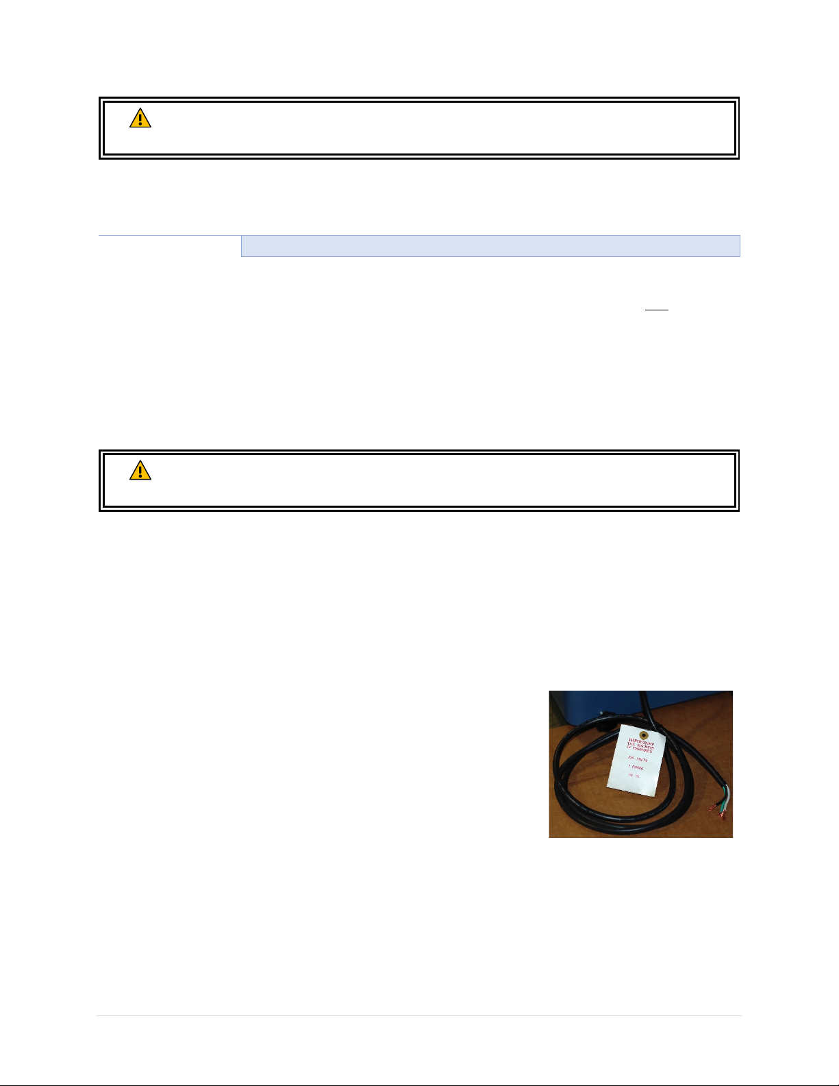
This machine is not pre-wired with a plug. A 7-feet long 14 AWG cord is
provided for connecting this machine to a power source. If you plan to
connect the machine directly to the electrical panel (“Hardwiring”).
Please ensure there is a readily accessible electrical disconnect near
the machine. Refer to section “Wiring Diagram” for wiring your
machine to a power source.
If you choose to connect this machine with a plug and a cord, please
use a UL/CSA listed plug. If you need an extension cord to connect to the power outlet, select a durable
cord type with high temperature rating (90C° or above). Both plug and power cord must be sized to
meet the amperage requirement of your machine.
16 | Page Oliver Machinery 10014 Planer
Page 17

Minimum cord size (AWG) required based on amperage draw and length of the cord:
Amps
Power Cord Length
25 feet
50 feet
75 feet
100 feet
> 100 feet
< 5
16
14
14
14
NR
5 to 8
14
14
14
12
8 to 12
14
14
12
10
12 to 15
12
12
10
10
15 to 20
10
10
10
NR
21 to 30
10
NR
NR
NR
Use properly sized wires that meet or exceed the power requirement of your
fire and machine damage.
*NR: Not Recommended
WARNING
machine. Using undersized wires may cause overheating and increase the risk of
Improper copper-aluminum wire connection is a fire hazard. If the power circuit
WARNING
available uses aluminum wires, use certified CU/AL wire connectors.
10014 Planer OLIVERMACHINERY.NET 17 | Page
Page 18
Setup
CAUTION
Use a dust collection system that is rated above 600 CFM. Doing so improves air
quality in the workplace, and protects the machine from jamming.
Piping of dust collection system introduces additional air resistance, and
decreases the effective CFM measured at the dust ports. Ensure
significant suction
from the machine.
Shop Preparation
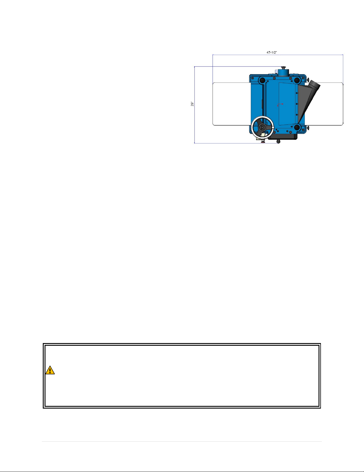
Space Requirement
The dimensions of this machine are 47-1/2”(L) x
29”(W). You will need additional spaces for
manipulating your workpiece, electrical
connection and dust collection.
Load Limits
This machine has a shipping weight of 470 lbs.,
and a net weight of 401 lbs. Please ensure all
lifting tools and building structures have adequate
load capacity, for transporting and supporting the
total weight of this machine, the operator, and
related items.
Electricals
Ensure a properly sized circuit and an electrical terminal are available nearby the machine. If the
machine is to be hardwired, there must be a readily accessible power disconnect nearby, so that the
machine can be disconnected from power source for servicing and adjustments. If the machine is to be
connected with a cord and a plug, please ensure a matching outlet is installed nearby the machine.
Please refer to the “Electricals” section in this manual for details regarding electrical requirements and
safety instructions.
Lighting
Adequate lighting is needed for operating this machine. Overhead, non-glare lighting should be installed
near the work area.
Safety Labels
If this machine introduces a new safety hazard to your work place. Please display proper warning signs
in highly visible location(s).
Dust Collection
Wood dusts created by this planer is a health hazard. Connect a dust collection system to this machine.
Check the air suction regularly to ensure the pipes are not jammed.
Dust masks should be available for using the planer.
at the dust port, so dust and debris can be effectively removed
18 | Page Oliver Machinery 10014 Planer
there is
Page 19
Receiving
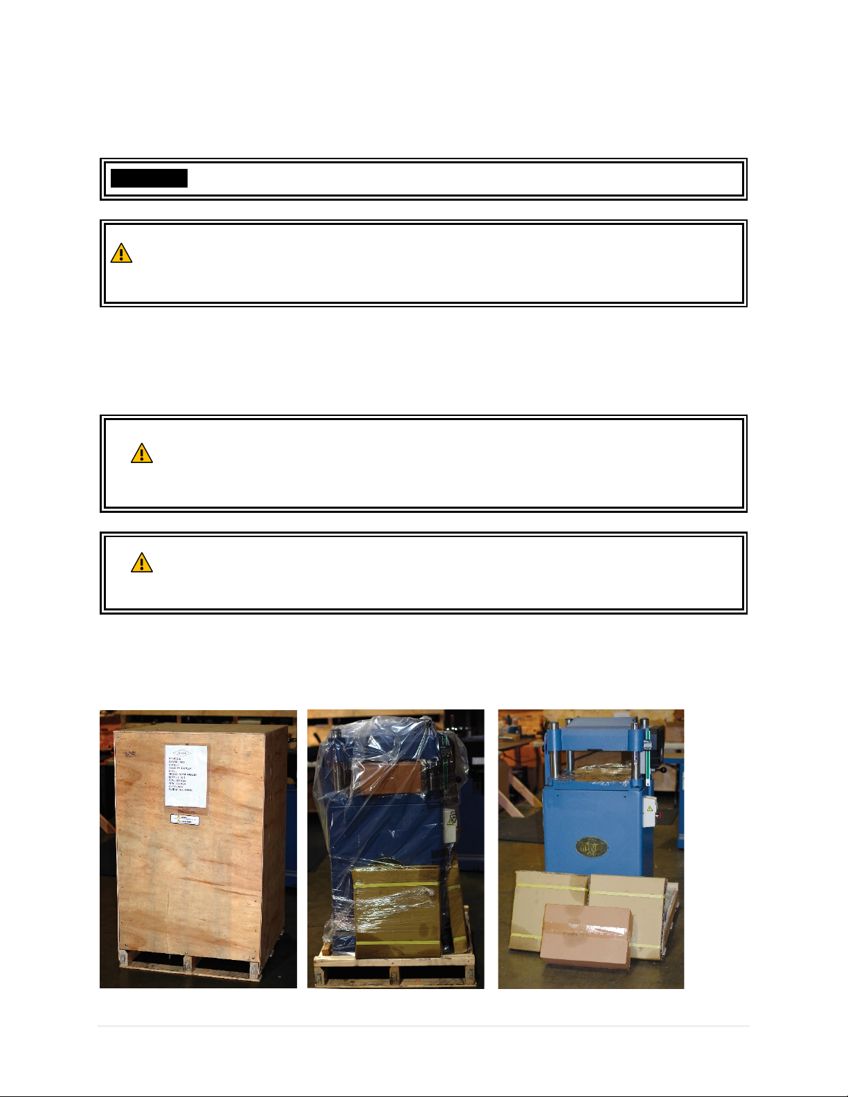
Your shipment should come with one wood crate. Upon receiving your shipment, check for any
significant damages before signing the delivery confirmation.
IMPORTANT
CAUTION
Moving Machine into the Shop
Your machine will be delivered by freight service, and it will be left outside of your workshop by default.
On the day of delivery, please be sure help is available to move the machine to its final location.
WARNING
WARNING
If items are damaged, please call us immediately at 1-800-559-5065
You may need to remove strapping that is used for securing your package.
Strapping may spring back violently when released and cause injury. Always
wear safety goggles and gloves for this task.
10014 Planer has a gross weight of 470 lbs. and a net weight of 401 lbs.
Safe moving techniques and proper lifting equipment required, or serious personal
injury may occur.
Your shipment may be secured by the straps. Do not lift your shipment by the
strap. They are not designed to hold the total weight of your shipment. They may
snap without warning and cause serious injury and machine damage.
Unboxing
Upon removing the crate cover, you should find a planer that is mostly assembled, and three paper
boxes that contain all the accessories. Everything is covered by a plastic bag.
10014 Planer OLIVERMACHINERY.NET 19 | Page
Page 20
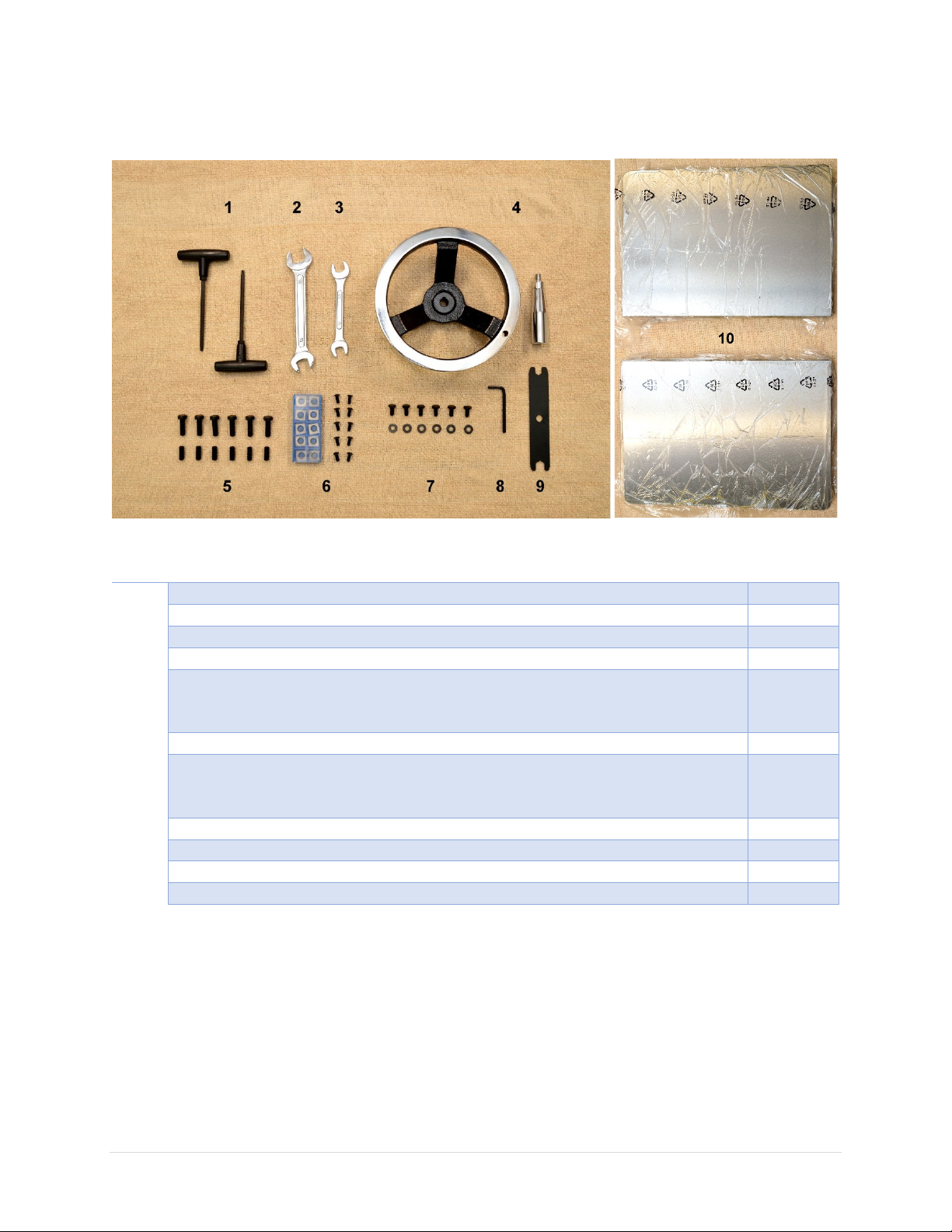
Inventory
Item
Description
Quantity
1
T-Handle Torx Drivers (T-25)
2
2
17/19mm Wrench
1
3
12/14mm Wrench
1
4
Height Adjustment Handwheel and Handle (Nut and label not shown)
1
5
Fasteners for Extension Table:
Set Screw (M8*1.25P*20)
6 each
6
Spare Cutter Inserts and Torx Screws
10 each
7
Fasteners for Dust Port:
Washer
6 each
8
4mm Hex Wrench
1
9
10/13mm Wrench
1
10
Cast Iron Extension Tables
2
11
4” Dust Hood (Not shown in the picture)
1
Carefully unwrap the packaging and make sure all components are included in the shipment. Lay out all
the items received and inventory them.
Hex Bolt (M8*1.25P*25)
Socket Head Cap Screw (M6*1.0P*12)
NOTICE: If you cannot find the item in the list above. Please check if they are still attached to the
packaging or inside the cabinet. Occasionally the item may have been pre-installed at the factory. Please
refer to the parts list section this manual to ensure you have all the components to set up this machine.
NOTICE: This machine comes with various standard sized, non-proprietary parts. If any of these parts are
missing, we be happy to deliver them to you. To have the machine up and running as soon as possible,
you can also find these parts at your local hardware store.
20 | Page Oliver Machinery 10014 Planer
Page 21

Additional Items Recommended for Machine Assembly
Item
Purpose
Safety Glasses
Protection
Disposable Gloves
Protection
Paper Towel / Rags
Cleaning
Rust Inhibitor
Cast iron table top rust protection.
Straight edge
Check alignments.
Metric Combination
Wrench Set
Assembly and Maintenance
Metric Hex Wrench Set
Assembly and Maintenance
Torque Wrench
Cutter inserts installation and for checking torx screw tension (50-55 lbs.T25 Star Bit Socket
Cutter inserts installation.
inch).
Removing Machine from Crate
When all items are ready for setting up the
machine, gently remove the machine from the
pallet. The planer is equipped with casters so it
can be push off the pallet with the help of a
ramp.
The base of the planer is bolted onto the pallet
to prevent shifting during transport. Remove
these screws and brackets if you see them. You
may reuse the hardware if the machine is to be
bolted onto the floor.
10014 Planer has a net weight of 401 lbs. All lifting devices must be capable to
WARNING
handle the load, or serious personal injury and machine damage may occur.
10014 Planer OLIVERMACHINERY.NET 21 | Page
Page 22

Cleaning
To prevent rusting, the cast iron bed and
extension tables of this planer are covered with
machine oil and a plastic film. Remove the
plastic film, then wipe off the machine oil with
paper towels or rags.
Once all the machine oil is removed, routinely
coat the unpainted cast iron surface with rust
preventive such as Boeshield® T-9 or paste wax.
Do not use rust preventives that contains
silicon, which is known to interfere with certain
finishes and glues.
Assembly
This planer is mostly assembled in the factory. There are a few more items to set up before the machine
is ready for a test run:
1. Install height adjustment handwheel.
2. Install dust hood.
3. Install extension tables.
4. Connect planer to a dust collection system.
5. Connect planer to power source.
The approximate time for cleaning and assembly is approximately 60 minutes.
22 | Page Oliver Machinery 10014 Planer
Page 23
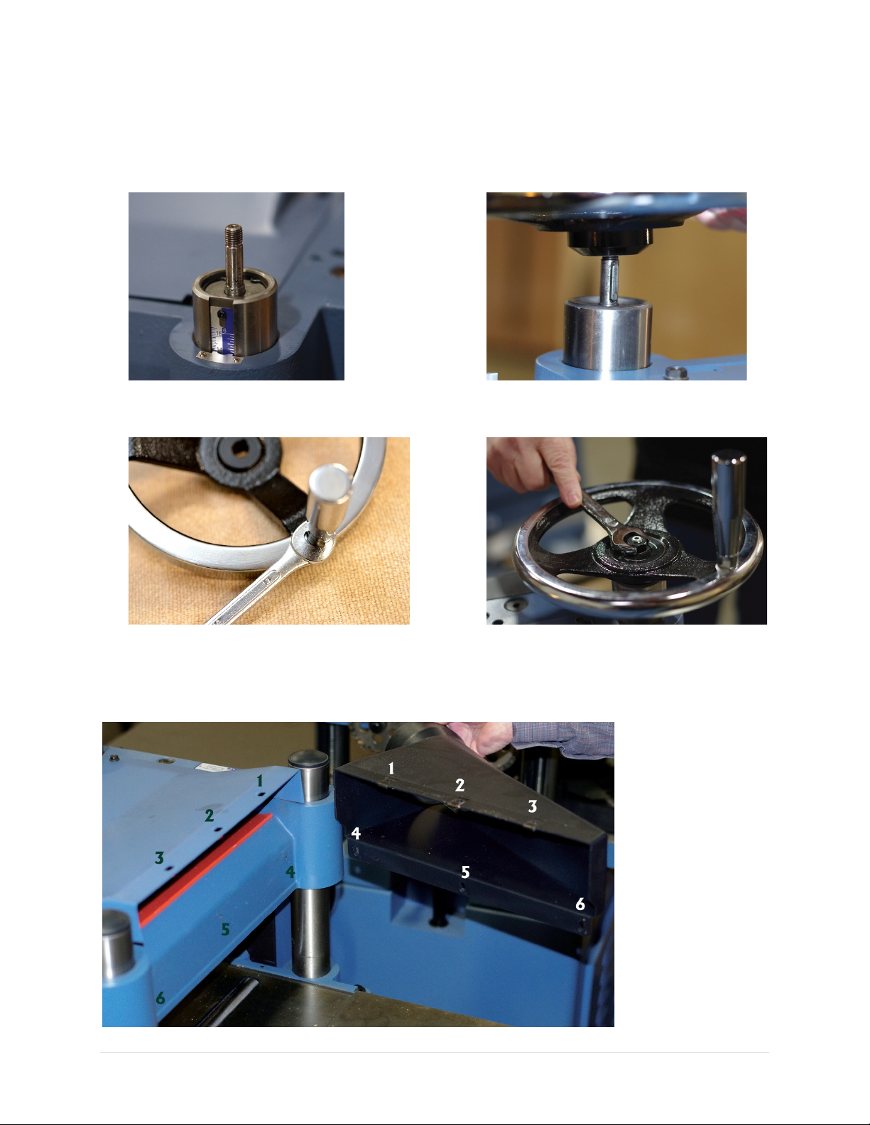
Installing Height Adjustment Handwheel
1. To install the height adjustment handwheel,
you will need the key, nut and the washer.
They are taped onto the handwheel shaft.
Carefully remove the tape to retrieve these
parts.
3. Insert the key into the keyway on
handwheel shaft.
4. Insert the handwheel and make sure the
keyway on the handwheel is aligned with
the key.
2. Install the handle of the handwheel and
tighten with a 14mm wrench.
Installing Dust Hood
Use the provided cap screws and washer (#7 in “Inventory”), to mount the dust port on top of the
cutterhead cover:
5. Install the washer and nut, then tighten the
nut with a 17mm wrench.
10014 Planer OLIVERMACHINERY.NET 23 | Page
Page 24
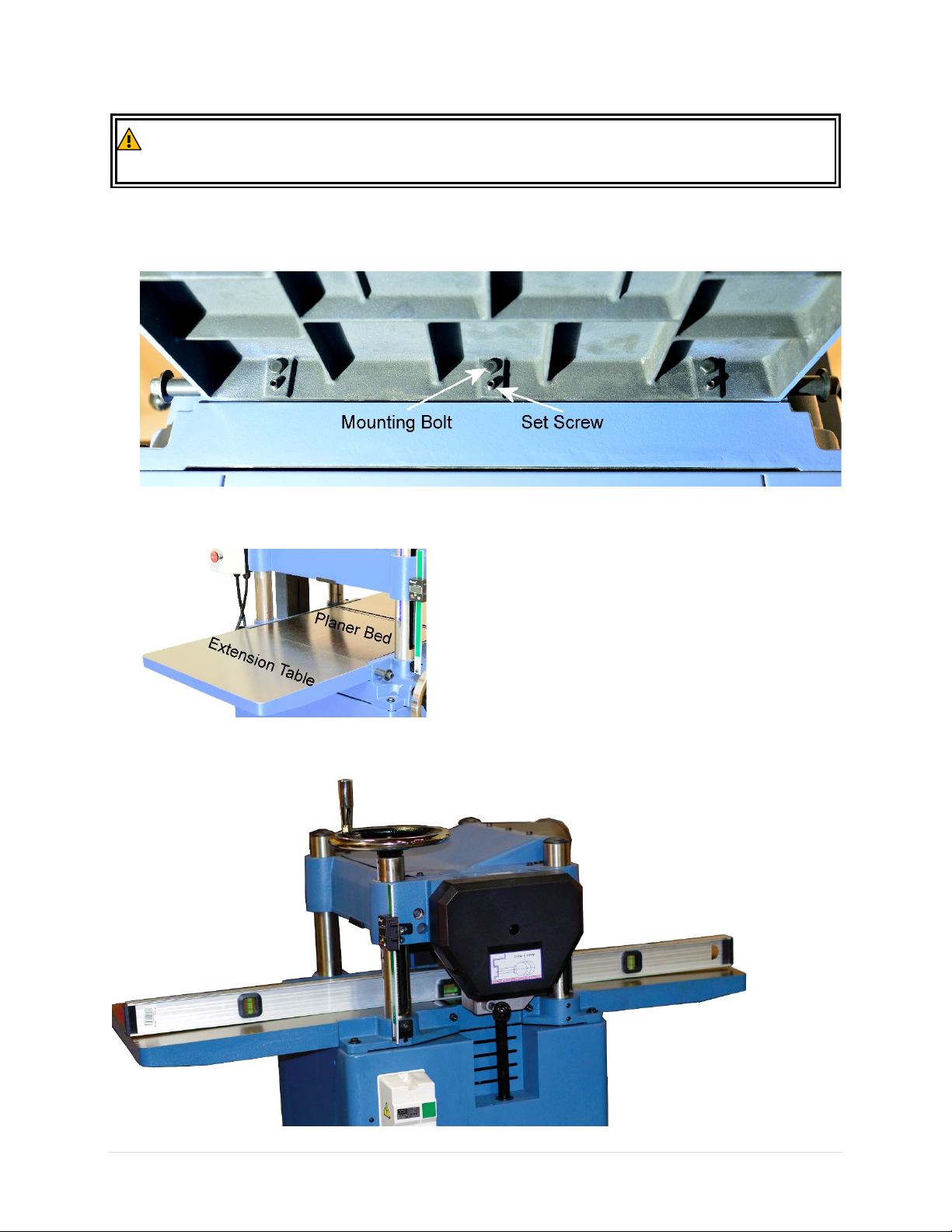
Installing Extension Tables
CA
Each extension table weighs
Get assistance to install the extension tables when needed.
UTION
1. Attach the extension table to the planer with the provided mounting bolts (#5 in “Inventory”). Do
not fully tighten the bolts yet. Just make sure it is tight enough to hold the extension table in place.
Then hand thread the set screws into the extension table.
2. Align the edge of extension tables with the edge of the planer bed. Make sure the edges are flush
with each other.
21 lbs. and it can be difficult to install by one person.
3. Use a straight edge to check if the extension tables are in parallel with the planer bed. At this point
the extension table should be slightly sagged.
24 | Page Oliver Machinery 10014 Planer
Page 25
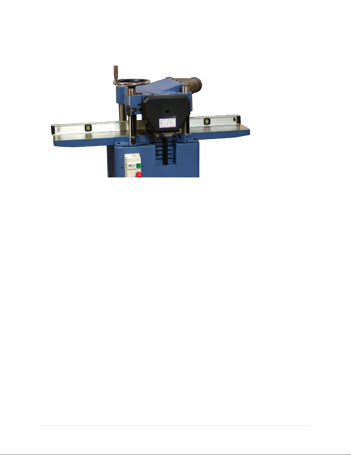
4. Rotate the set screws with a hex wrench to raise the extension tables. For each set screw, make
small, incremental adjustments, and then move on to the next set screw. Repeat until both
extension tables are in parallel with the planer bed. If a set screws become too difficult to turn, you
may need to slightly loosen the mounting bolts before continue to raise the extension table.
5. When the extension tables are in parallel with the planer bed, tighten all mounting bolts.
Recheck table parallelism for one more time.
6. Save these instructions as the extension tables will need to be adjusted from time to time.
10014 Planer OLIVERMACHINERY.NET 25 | Page
Page 26
Dust Collection
Wood planer can generate a lot of wood shavings and dusts. Connect the dust collection system to this
machine. Minimum CFM requirement for this planer is 600 CFM at the dust port, which means your
dust collection system should have a rating greater than 600 CFM, as air friction from the ducts reduces
the effective CFM at the dust ports.
Running this planer without dust collection system, or using a dust collection
system with inadequate suction, will cause dust and shavings to accumulate
IMPORTANT
inside the planer. This can damage the machine and cause other hazardous
situations. Check your dust collection system regularly to make sure it is not
jammed or filled up.
Wiring and Grounding
DANGER
Deenergize the electrical circuit before touching any enclosed, electrified parts.
Touching electrified part WILL result in serious personal injury or death.
All electrical work must be done by a qualified electrician, and must meet the
electrical code in your area.
WARNING
Make sure the voltage of your power circuit matches the specifications on the
nameplate of the machine, and the circuit is sized to supply power to the planer.
Wiring Instructions
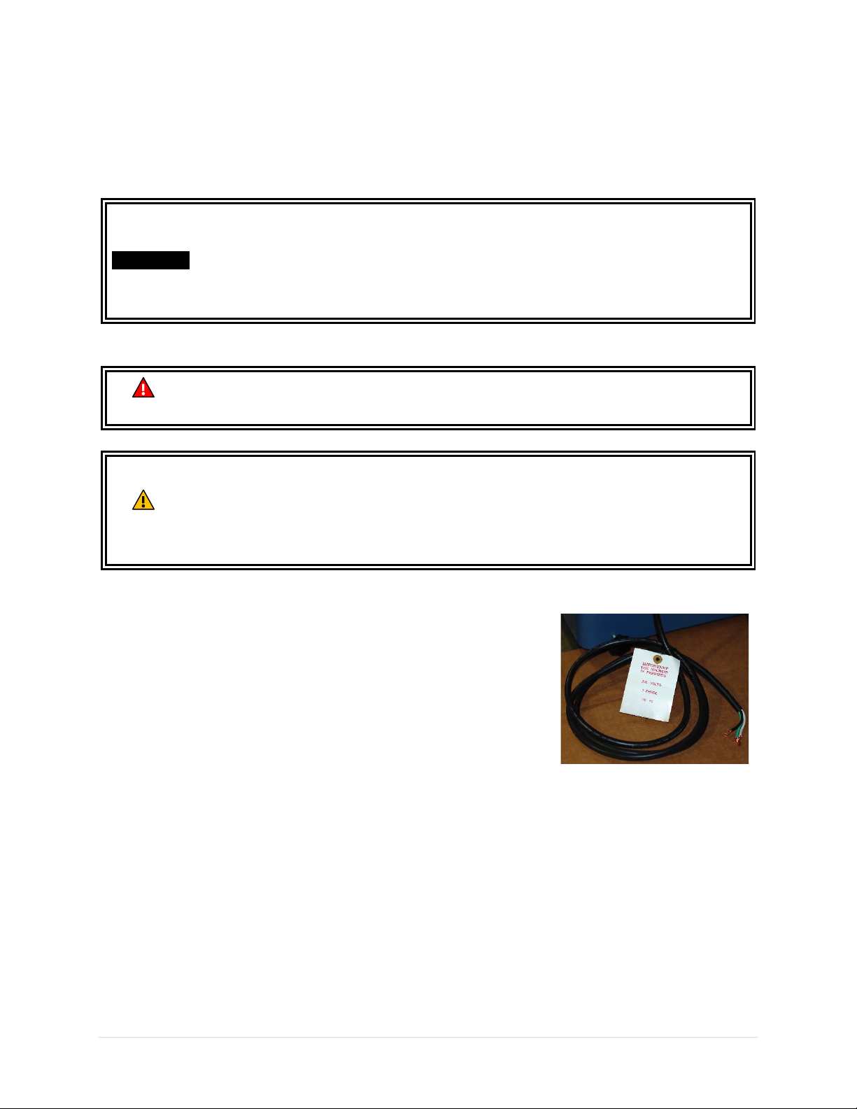
This machine is not pre-wired with a plug. A 7-feet long 14 AWG cord is
provided for connecting this machine to a power source. If you plan to
connect the machine directly to the electrical panel (“Hardwiring”).
Please ensure there is a readily accessible electrical disconnect near
the machine. Refer to section “Wiring Diagram” for wiring your
machine to a power source.
If you choose to connect this machine with a plug and a cord, please
use a UL/CSA listed plug that is sized to meet the amperage
requirement of your machine.
Break-in Period
Congratulations for getting this machine assembled and ready for a test run! Please set a reminder to
service this machine as it goes through the break-in period. Completing these services will maximize the
performance and longevity of your machine.
After 16 hours of operation: Adjust V-belt tension.
After 50 hours of operation: Replace gearbox oil.
26 | Page Oliver Machinery 10014 Planer
Page 27
Controls and Components
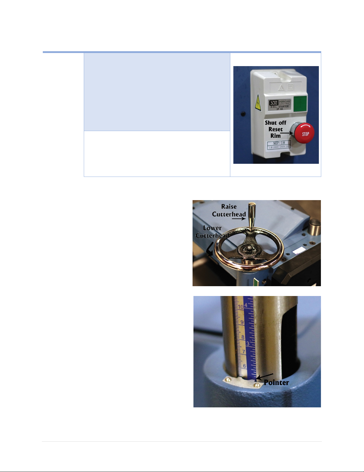
To Turn Off
Press the “STOP” button.
it needs to be
To Turn On
Press the green “START” button.
ON / OFF Switches
Machine
NOTICE: When STOP button is pressed,
reset before the planer can start again. To reset,
rotate the serrated rim clockwise. The STOP button
will pop up when it is reset.
NOTICE: The planer will shut down if it is overloaded.
Press STOP to reset overload protection.
Machine
NOTICE: The machine will only start when the STOP
button is reset.
Cutterhead Height Adjustment
The cutterhead height adjustment handwheel is
located on the side of the planer, right below the
digital readout.
Turn CLOCKWISE to lower the cutterhead.
Turn COUNTERCLOCKWISE to raise the cutterhead.
Each rotation of the handwheel changes the height by
approximately 1/8” (3mm).
Cutterhead Height Scale
The cutterhead height scale is located on the right
column next to the digital readout. A metal pointer
marks the current height of the cutterhead.
10014 Planer OLIVERMACHINERY.NET 27 | Page
Page 28
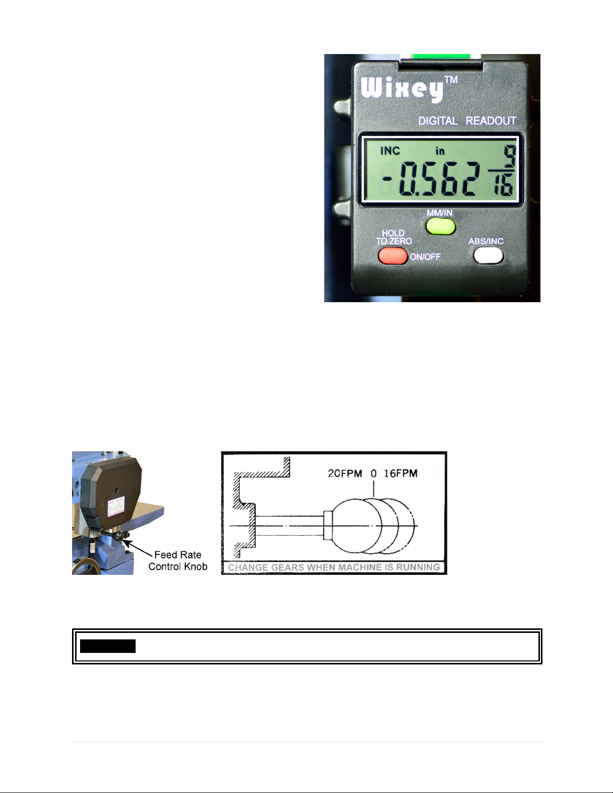
Digital Readout (DRO)
Only change feed rate when the machine is running at full speed. Failure to do so
may cause the gearbox to jam and damage the machine.
The Wixey DRO allows operators to measure the
depth of the cut with 1/32” resolution.
• Press the ON/OFF button to turn on/off the
DRO.
• Press the MM/IN button to toggle measuring
unit between metric (mm) and US standard
(inch). The fraction inch value will appear if
the measurement is a multiple of 1/32”
• Press the ABS/INC button to toggle between
absolute measuring mode and incremental
mode.
• Value in INC mode will be reset when
switching to ABS mode.
• To reset the reading to zero in ABS mode,
hold the ON/OFF button
Feed Rate Control
10014 Planer can feed stock at 16/20 FPM (feet-per-minute). To change feed rate, shift the position of
the feed rate control knob when the machine is running at full speed with no load:
• Push in: 20 FPM
• Pull out: 16 FPM
• In between: 0 FPM (Neutral)
IMPORTANT
28 | Page Oliver Machinery 10014 Planer
Page 29
Components for Planing Wood
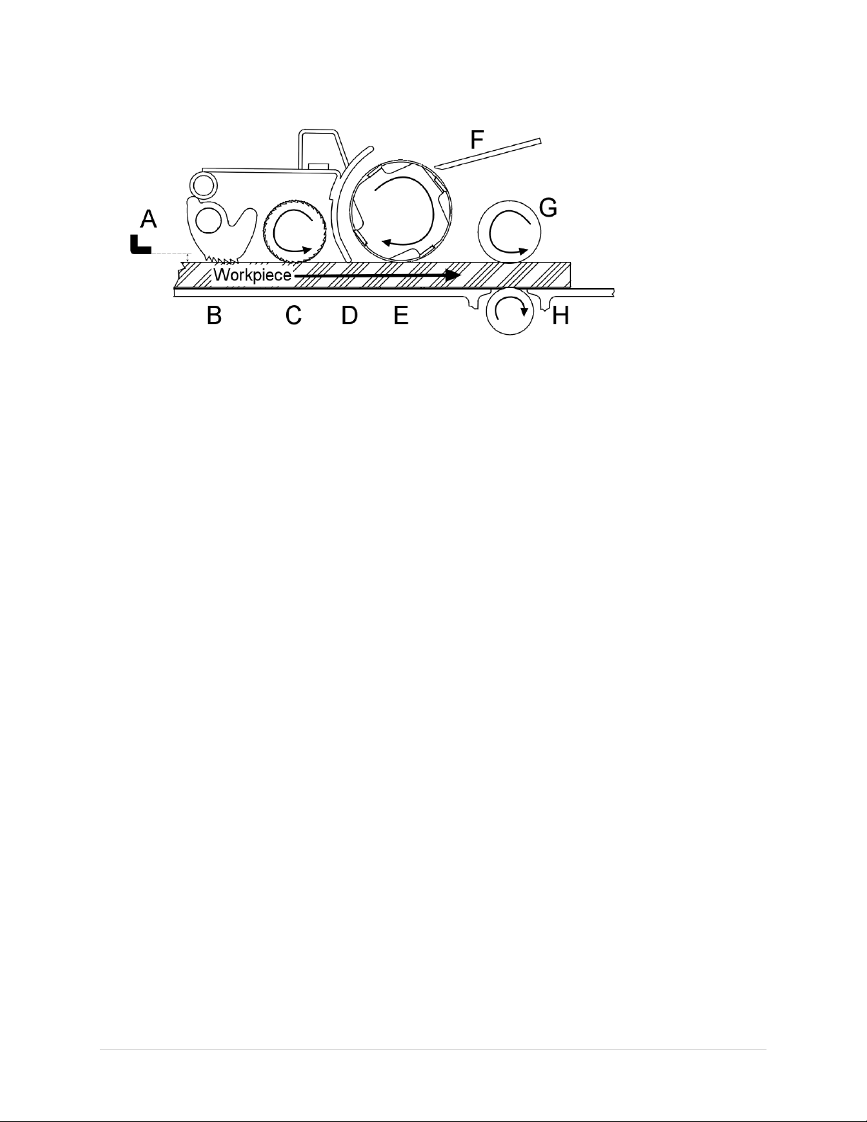
This diagram shows components involved for planning a piece of wood:
How it works:
1. When a workpiece enters the planer, with planer’s depth of cut properly set, it will clear the
depth limiter[A]. For workpiece less than 6”, it is possible to bypass the limiter and receive a
deeper cut.
2. The anti-kickback fingers [B] then engage the workpiece to prevent accidental kick-back.
3. As the workpiece moves further into the planer, it will engage the infeed roller [C]. The infeed
roller will bring the workpiece towards the chip breaker [D] and the cutterhead [E].
4. As the cutterhead cuts on the workpiece, the woodchips will be broken down by the chip
breaker.
5. The chip breaker and the chip deflector [F] then divert the woodchips towards the dust port for
removal.
6. As the workpiece leaves the cutter head, it will engage the outfeed roller [G], which helps
pulling the workpiece away from the planer.
7. The workpiece will also engage the bed roller[H] which helps reducing resistance as the
workpiece moves along the planer table. The height of the bed roller can be adjusted to
accommodate workpiece with various roughness.
10014 Planer OLIVERMACHINERY.NET 29 | Page
Page 30

Test Run
Each planer has been inspected and calibrated before leaving the factory to meet our quality and
precision standards. Due to various reasons, the machine may need to be re-adjusted when it arrives at
your workshop. It is recommended to complete the test run before using the planer for production
work, and repeat the test run if the planer is relocated.
Step 1: Verify all electrical components are functional.
1. Remove all tools and debris from the machine.
2. Push STOP button.
3. Connect machine to the power source.
4. Turn the rim of the STOP button clockwise to reset the safety shutoff mechanism.
5. Press the green START button. The machine should be running with no excessive noise and
vibration.
6. Press STOP button to turn machine off.
7. Without resetting the STOP button, attempt to restart the machine by pressing the START
button. The machine should NOT start.
8. Reset the STOP button to restart the machine. Disconnect the machine from power source while
the machine is running, then reconnect machine to power. The machine should NOT restart.
Step 2: Verify the planer headstock is functional and calibrated.
1. Connect planer to a dust collection system.
2. Lower the headstock all the way down. The headstock should stop at approximately 1/4" above
the planer table.
3. Raise the headstock all the way up. Ensure all the anti-kickback fingers can move freely.
4. Turn on the DRO to check the readings of digital readout. The readings should reflect the
movement of the headstock.
5. Prepare a piece of good quality, straight grain wood board with flat bottom for a test run. It is
advised to choose a board that is close to 15” wide and at least 2 feet long.
6. Lower the headstock to remove 1/16” of the workpiece for the test run.
7. Start the dust collection system and the planer. Gently feed the workpiece towards the infeed
roller. Ones the infeed roller engages the workpiece, it should pull the workpiece through the
planer. Verify the entire top surface has been cut.
8. Inspect the workpiece for defective finish.
9. Use a caliper to measure the thickness of each side to ensure the cutterhead is parallel with the
planer table. If the thicknesses are the same, check if the reading is the same as shown on the
headstock height scale.
10. Check for excessive snipes. Minimum amount of snipe may occur at the ends of the board and it
is expected.
11. While the machine is running idle, move the feed rate control knob to change feed rate. This
ensures the gearbox and feed rate control knob is functional.
12. Hit STOP to turn off the planer when all tests complete.
Congratulations for completing the test run! Now your planer is ready for production work. If you
discover any issue from the tests, please refer to the troubleshooting section and maintenance section
for how to diagnose the issue and make adjustments.
30 | Page Oliver Machinery 10014 Planer
Page 31

Operation
For safety and best results, please take the following steps for operating this machine.
Step 1: Preparation
Only Use Natural, Good Quality Wood
Only plane natural wood materials that is in good quality. Cracked stock, board with loose knots,
plywood and other engineered wood products can break apart and cause severe kickbacks, which can
lead to severe injuries and machine damages.
Do not plane treated lumber or anything that contains harmful chemicals, as this will spread wood dusts
that contain such harmful chemicals. NEVER plane boards that are shorter than 7”as mentioned in the
specifications.
Inspect the Workpiece
Carefully inspect the workpiece for foreign objects. Nails, staples, rock chips and other objects
embedded on the wood surface will damage the planer. To avoid chipping/dulling the cutter inserts, it is
advised to clean a workpiece with a stiff brush to remove all dirt and foreign objects before planing,
especially for rough sawn or reclaimed lumber. Use metal detector to scan for metal as needed.
Check Moisture Content
Check moisture content of the workpiece before operation. “Green wood” with moisture content over
20% will not cut properly and may jam the machine. Excessive moisture content will also cause planer’s
unpainted surface to rust. Besides, as the workpieces dries, the planed surface will become fuzzy, and
the workpiece may wrap. It is recommended to allow the workpiece to dry and stabilize before it is
processed.
Wrapped Stock
Workpiece should have a flat bottom to be processed by a planer. It is acceptable to process a slightly
cupped board with the cupped side facing down and begin with light cuts. Boards with moderate
cupping, bowing or twisting should have one side face-jointed before being processed by a planer.
Avoid using boards with severe wrapping, as they can be unstable and might cause severe kickbacks
during operation.
Glue-Ups
Glue left on the workpiece surface can dull the cutters and reduce cut quality. Scrape off all glue from
the workpiece before operation.
Wood Grain Direction
This planer is designed to plane WITH the grain direction of the wood. Do not plane cross-grain or end-
grain. Severe kickback and chipping may occur.
10014 Planer OLIVERMACHINERY.NET 31 | Page
Page 32

Step 2: Setting Depth of Cut and Feed Rate
This planer is capable of removing at most 1/8” per pass. For stock that is less than 6” wide, the planer
can cut as much as 1/4" per pass. For best results, it is recommended to take light passes with low feed
rate when approaching the desired thickness.
Wood Hardness
Depends on the hardness and brittleness of the wood type, operator should adjust the maximum depth
of cut and feed rate accordingly. For workpiece that is hard/brittle, reduce the depth of cut and feed
rate.
For your reference, this Janka scale shows the hardness of wood types that are commonly used. It ranks
the hardness of various wood types by measuring the amount of force (in lbs.) required to embed a
0.444” steel ball halfway into the wood.
Janka Scale
BALSA
EASTERN WHITE PINE
BASSWOOD
WHITE PINE
HEMLOCK
CHESTNUT
RED ALDER
DOUGLAS FIR
SYCAMORE
CEDAR
CHERRY
BLACK WALNUT
RED OAK
WHITE ASH
WHITE OAK
HARD MAPLE
ZEBRAWOOD
WENGE, RED PINE
PADAUK
ROSEWOOD
PURPLE HEART
RED MAHOGANY
EBONY
IRONWOOD
TEAK
IPE
70
380
410
420
500
540
590
660
770
900
995
1010
1155
1290
1320
1360
1450
1575
1630
1725
1780
1860
2697
3220
3260
3684
32 | Page Oliver Machinery 10014 Planer
Page 33
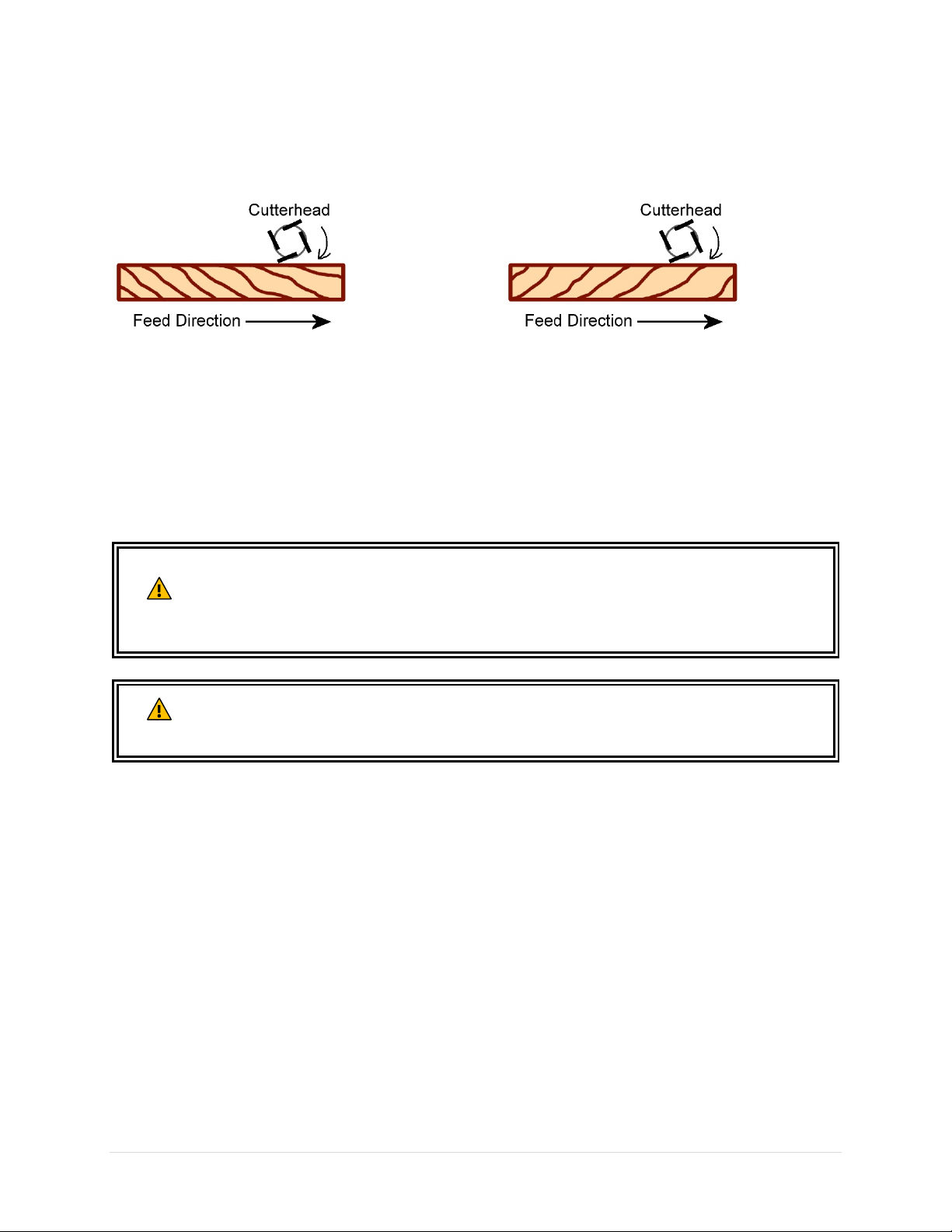
Step 3: Select Feed Direction
Inspect the workpiece and identify the direction of the edge grain. Choose a feed direction such that
workpiece will receive a downhill cut.
Good – Planer Cuts Downhill
Not Ideal – Planer Cuts Uphill
Sometimes it is impossible to perform a downhill cut for the entire length of a workpiece. In this case,
try feeding the workpiece in opposite direction and see what works best. Reducing the depth of cut and
feed rate can also help improving cut quality.
Step 4: Planing Wood to Desired Thickness
ALWAYS wear goggles, and other protection device when operating this machine.
Stay on the side of the planer next to the power switch to avoid kickback related
WARNING
accidents. NEVER look inside the planer during operation. Failing to comply may
result in serious injuries or death.
Use ear protection device to prevent hearing loss. Ensure dust collection system is
CAUTION
functional and use dusk mask to avoid inhaling harmful airborne particles.
With the above preparation steps completed, the workpiece is ready for planing.
1. Please put on all protection devices before proceed. If you have a long workpiece, please make sure
it is properly supported throughout the process.
2. Measure the thickness/height of the workpiece, then move the cutterhead no more than 1/16”
below the highest/thickest point of the workpiece. This allows the feed rollers to properly engage
the workpiece, and at the same time not taking too much materials off for a test pass.
3. Turn on dust collection system and the planer.
4. While standing on the side of the planer, place the workpiece on the table with the flat side down.
Gently feed the workpiece towards the infeed roller. Once the infeed roller engages the workpiece,
allow the machine to feed the workpiece. DO NOT force feed the workpiece through the planer.
If the infeed roller does not engage the workpiece:
Headstock height is set too high. Stop the machine. Wait for the machine to come to a complete
stop. Raise the headstock and remove the workpiece. Reduce the initial headstock height, and
restart form step 3.
10014 Planer OLIVERMACHINERY.NET 33 | Page
Page 34

If the machine stalls or the workpiece gets stuck:
Headstock height is set too low. Stop the machine and wait for the machine to come to a complete
stop. Raise the headstock and remove the workpiece. Decrease the depth of cut, and restart from
step 3.
5. If the workpiece is feeding properly, wait until the entire workpiece clears the outfeed roller, then
remove the work piece.
6. After the initial pass, measure the thickness at the midsection of the workpiece.
If more material needs to be removed, continue with the following steps.
7. If you need to remove a lot of material, run a few passes with deeper cuts, then finish with a light
pass with shallow cuts and slow feed rate.
8. Turn on the digital readout (DRO), and use the INC mode to measure the depth of cut for each pass.
If your DRO is already running in INC mode, you can reset the readings by switching to ABS mode
and then come back to INC mode.
9. Using the DRO as depth gauge, lower the cutterhead. Each pass should remove no more than 1/8”
for workpiece wider than 6”, and no more than 3/16" for workpieces 6” or less. Reduce maximum
depth of cut for harder wood types.
10. Upon completion of each pass, reset the reading of DRO. Use a caliper to measure workpiece’s mid-
section thickness, and decide the depth of cut for the next pass.
11. Repeat the process until the desired thickness is achieved.
Turn machine off when operation completes.
34 | Page Oliver Machinery 10014 Planer
Page 35
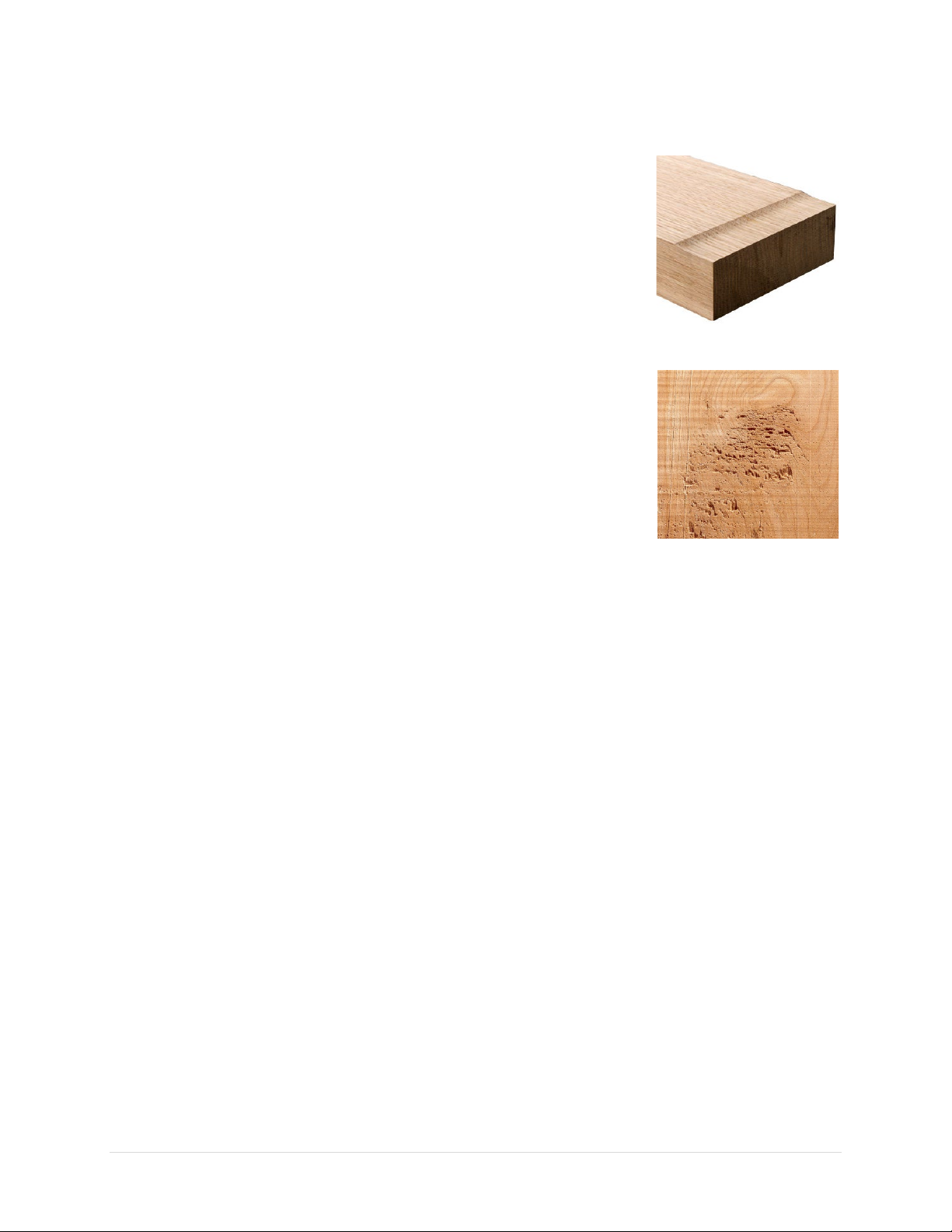
Common Cutting Problems
Snipe
When a workpiece is not properly supported as it enters or leaves the
machine, the ends of the workpiece will have more materials removed than
the rest of the section. To mitigate this problem, hold the workpiece up
slightly as it enters and leaves the machine. Sometimes, a small amount of
snipe is inevitable, and the best way to fully eliminate sniping is to prepare a
workpiece with extra length, and then trim the ends when planing is done.
Chipping
Happens when making a cut against the grain direction. See “Uphill” cut in
Step 3 of this section. For highly figured lumber and areas near the knot,
some amount of chipping is normal. In this case, moistening the
problematic area before planing can sometimes mitigate the issue.
Chipping can also cause by dirty or dull cutters. If chipping happens while
planing straight grain stocks. Inspect the cutter inserts and remove all resin
buildups. Rotate/replace dull cutter inserts when they are dull.
Indentation
This can happen when foreign object is pressed on the workpiece when it passes through the planer.
Remove all the resin buildups from the rollers, cutterhead and the table. Also check the dust collection
system and ensure all the wood chips generated are effectively removed. Adjust the chip breaker and
chip deflector as needed.
Fuzzy Grain
Can happen when planing wood with high moisture content or if the cutter is dull. Sometimes fuzzy
grain is unavoidable due to the nature of certain wood types. To mitigate this issue, avoid using wood
with high moisture content and use sharp cutters.
10014 Planer OLIVERMACHINERY.NET 35 | Page
Page 36
Accessories
Oliver Machinery has a collection of accessories and add-ons to enhances productivity of your planer. To
purchase these items, please call us at 1-800-559-5065, our representatives are available Monday
through Friday, 9AM - 5PM pacific time.
You may also purchase them online: WWW.OLIVERMACHINERY.NET/ACCESSORIES
E-mail our parts department: [email protected]
Using unapproved accessories may cause machine to malfunction, resulting in
WARNING
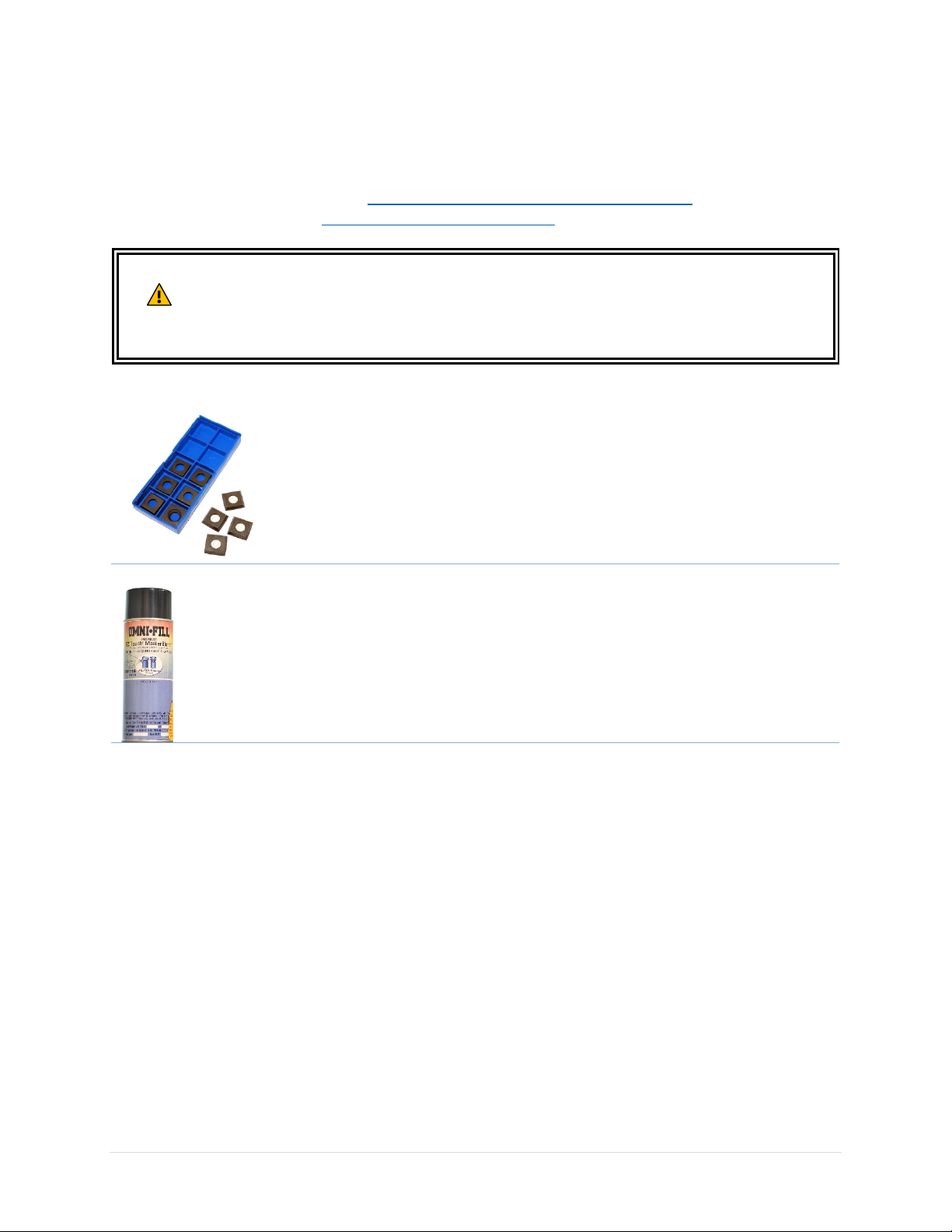
Cutter Inserts
Touchup Paint
serious injury and/or machine damage. Only use accessories recommended for
this machine.
Genuine four-sided indexable carbide cutter insert that will fit the cutterhead
of Oliver 10014 Planer. Made in Germany.
Parts number: P-15mm 4S
Keeping all painted surface in good condition not only keeps your machine
looks nice, it keeps rusts away. We have pre-mixed spray paint available in
Oliver-Blue for purchase.
or
Please visit our website at WWW.OLIVERMACHINERY.NET/ACCESSORIES for other recommended
accessories.
36 | Page Oliver Machinery 10014 Planer
Page 37
Maintenance
restarting the machine. Failure to comply can cause serious injury!
Interval
Component
Every day
Remove dust buildups from planer and dust collection system.
Inspect power cord for sign of aging and damages. Replace as needed.
Every week
Inspect and clean cutterhead, rollers and anti-kickback fingers. Remove any
dust and resin accumulation.
Inspect/rotate/replace worn cutter inserts.
Apply rust protectant on unpainted cast iron surfaces.
Verify extension tables are level with the planer bed. Adjust as needed.
Every month
Check V-belt tension and replace if belt shows signs of cracking or glazing.
Every 4-6 months
Remove dust buildups from motor and the cabinet.
Inspect table chain for chain slacks.
Check parallelism between the table and cutterhead, and the rollers.
Component
Interval
Types of Lubricant
Reference
B - Feed roller shafts
Every 30 hours
SAE-30 oil.
Figure 1
C - Drive chains and
sprockets
Monthly
General purpose grease
Figure 2
D - Lead screws (x4)
Once every 3 months
General purpose grease
E - Columns (x4)
Clean and lubricate
weekly
Light coat of SAE-30 oil
F - Gear box
Replace gear box oil
Standard gear oil, 70-90 weight.
Remove gearbox cover to access drain plug
Refill oil until it reaches the fill plug.
Figure 3
G - Outfeed roller
Clean and lubricate as
Very light coat of SAE-30 oil.
Figure 4
H - Infeed roller
I - Anti-kickback
fingers
J - Bed roller
Figure 5
K - Table chain and
Every 4 to 6 months
Grease, or good quality cycle chain
components.
Figure 6
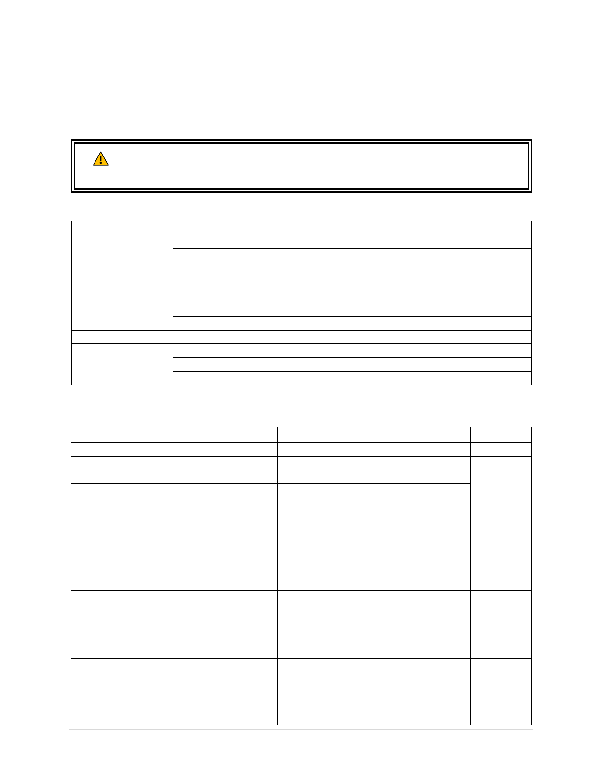
Routine maintenance keeps your planer in top shape. Please follow the maintenance schedule below,
and use the maintenance record worksheet attached in the back of the manual to document all tasks
completed. NOTICE: Maintenance schedule may vary for individual users due to different situations and
safety requirements.
Disconnect machine from the power source before any maintenance work is
WARNING
performed. After servicing the planer, remove all wrenches and tools before
Maintenance Schedule
Notice: Motor bearings are permanently sealed and lubricated, and do not require lubrication.
Lubrication Schedule
after first 50 hours,
then every year.
and fill plug. Drain and recycle used oil.
needed.
sprockets
lubricant.
Remove motor access panel to access
10014 Planer OLIVERMACHINERY.NET 37 | Page
Page 38
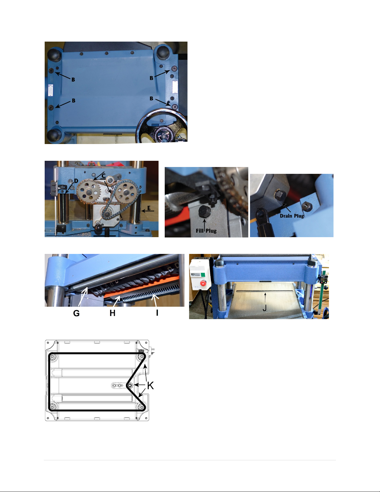
Figure 1
Figure 2 Figure 3
Figure 4 Figure 5
Figure 6
38 | Page Oliver Machinery 10014 Planer
Page 39
Instructions for Maintenance and Adjustments
restarting the machine. Failure to comply can cause serious injury!
Disconnect machine from the power source before any maintenance work is
WARNING
performed. After servicing the planer, remove all wrenches and tools before
Remove Planer Top Cover
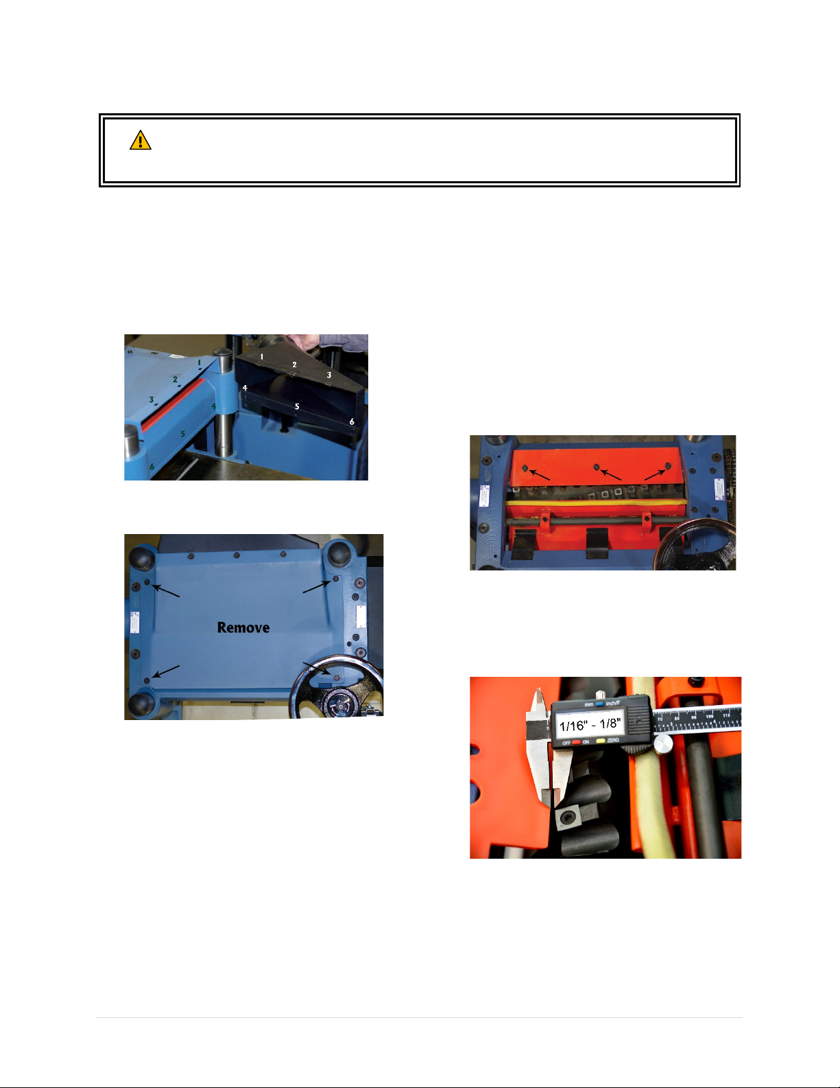
This allows you to service the cutterhead, chip
deflector, and chip breaker.
1. Disconnect planer from power source!!
2. Remove dust port.
3. Remove the planer cover by removing the
four cap screws from the top of the planer.
Adjust Chip Deflector Clearance
The chip deflector was pre-installed in the
factory and should not require adjustments
initially. If the gap between chip deflector and
cutterhead goes beyond the 1/16” - 1/8”
tolerance, adjustment is needed.
1. Disconnect planer from power source!!
2. Remove dust port and top cover.
3. Loosen the three bolts that secures the chip
deflector.
4. Adjust the distance between the chip
deflector and the cutterhead. The entire
edge of the chip deflector should be no less
than 1/16” away from the closest point of
the cutter head, but no more than 1/8”.
5. Re-tighten the bolts to secure the chip
deflector, then reinstall the top cover and
dust port.
6. Remove all wrenches and tools before
restarting the planer.
10014 Planer OLIVERMACHINERY.NET 39 | Page
Page 40
Service Cutterhead and Rotate Cutter Inserts
CAUTION
Cutter inserts on the cutterhead are extremely sharp. Protect your hands with thick
leather gloves to avoid injuries.
1. Disconnect planer from power source!!
2. Remove dust port and top cover.
3. Remove dusts and resin accumulations on
the cutterhead and the area nearby.
4. Rotate the cutter inserts 90° clockwise
when they get dulled or nicked. Use a
permanent marker to mark the new edge to
be used.
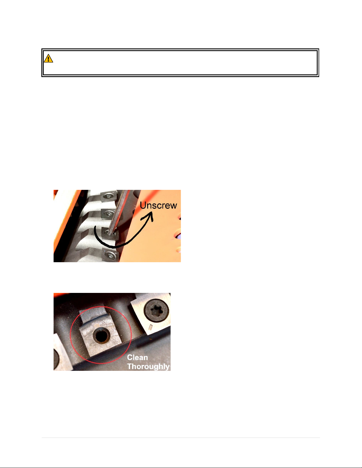
5. To rotate/replace a cutter insert, remove
the torx screw with a T-25 torx bit. Turn
COUNTERCLOCKWISE to loosen the screw.
8. Inspect the torx screw. Replace any
damaged screws. Lubricate the screw
thread with a thin coat of light weight
machine oil.
IMPORTANT: Do not use excessive amount
of lubrication, or the torx screw and the
cutter insert will not sit properly.
9. Using a torque wrench, re-tighten the torx
screw with 50-55 lbs.-inch of torque.
IMPORTANT: Do not overtighten the screw
or the inserts may break. Do not use power
tools to tighten the torx screws as it can
strip the screws.
10. Reinstall top cover and dust port when
cutterhead service completes.
6. With the cutter insert removed from its
platform, thoroughly clean the cutter insert
platform with a vacuum or compressed air.
IMPORTANT: Obstacles between the insert
and cutterhead platform will create uneven
pressure against the insert. This will lower
cut quality and may cause the insert to
crack.
11. Remove all wrenches and tools before
restarting the planer.
7. Reinstall the cutter insert with the marked
cutting edge facing out.
40 | Page Oliver Machinery 10014 Planer
Page 41
Adjust Belt Tension
If belt tension needs adjustment:
CAUTION: Belt and pulleys may be hot
after operations. Allow components to cool
before servicing.
IMPORTANT: After initial break-in period. The
V-belt should stretch by some amount. Check
and adjust belt tension after 16 hours of
operation.
1. Disconnect planer from power source!!
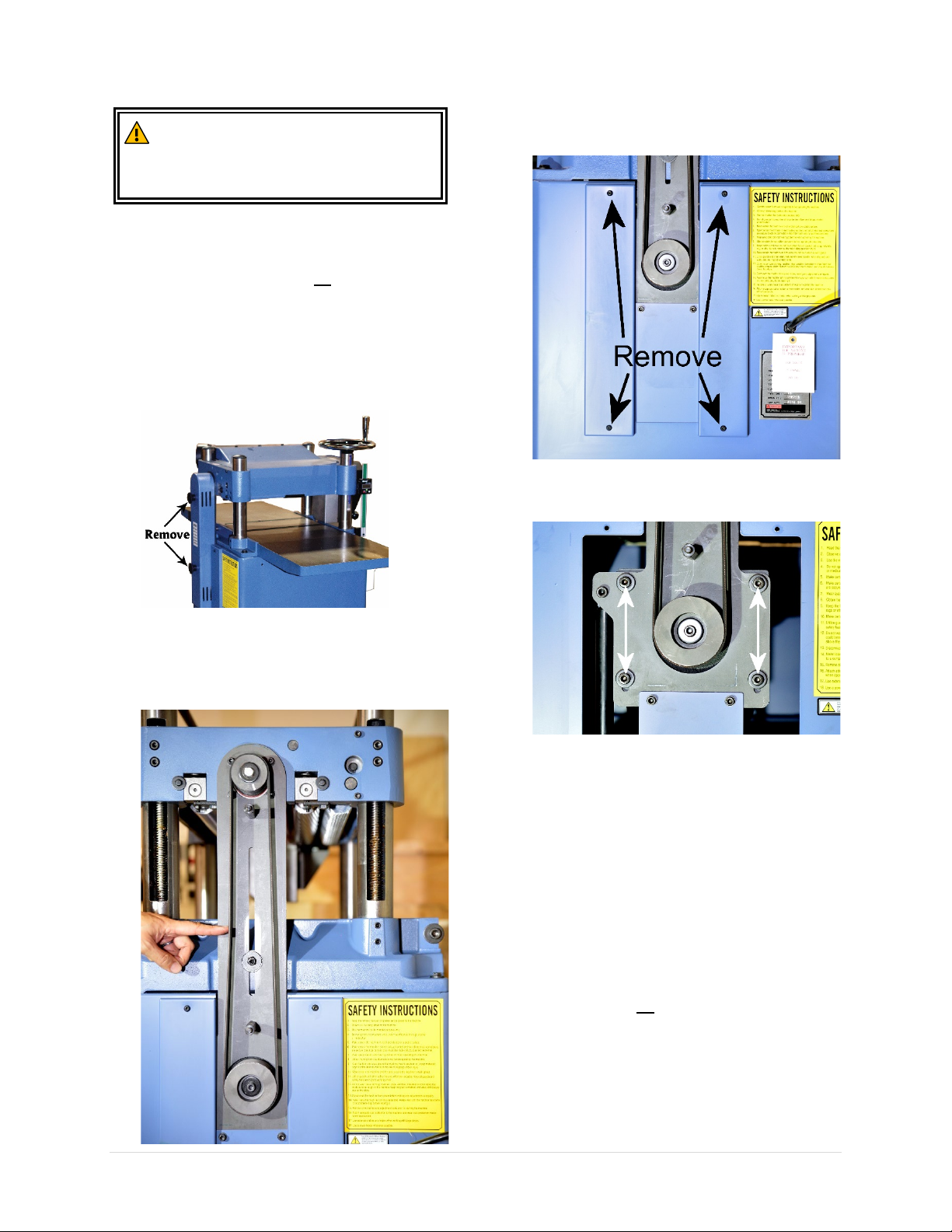
2. Remove the knobs that hold the belt cover
in place.
4. Remove the side panels to gain access to
the motor mount cap screws.
5. Loosen the cap screws and lower the motor
to tighten the belt. If the belt becomes too
tight, raise the motor.
3. Apply moderate pressure on the V-belt
midway between the two pulleys. Properly
tensioned V-belt should deflect by
approximately 1/4“.
6. Re-tighten the motor mount cap screws
and re-install the side panels when belt is
properly tensioned.
If belt needs to be replaced
7. Loosen the belt and roll the belt off the
pulleys.
8. Install new belts and make sure the belt sits
into the grooves of the pulleys.
9. Adjust belt tension.
10. Set a reminder to readjust belt tension after
the new belt is broken in. The process takes
approximately 16 hours of run time.
When belt maintenance completes
11. Reinstall all the panels and covers.
12. Remove all wrenches and tools before
restarting the planer.
10014 Planer OLIVERMACHINERY.NET 41 | Page
Page 42
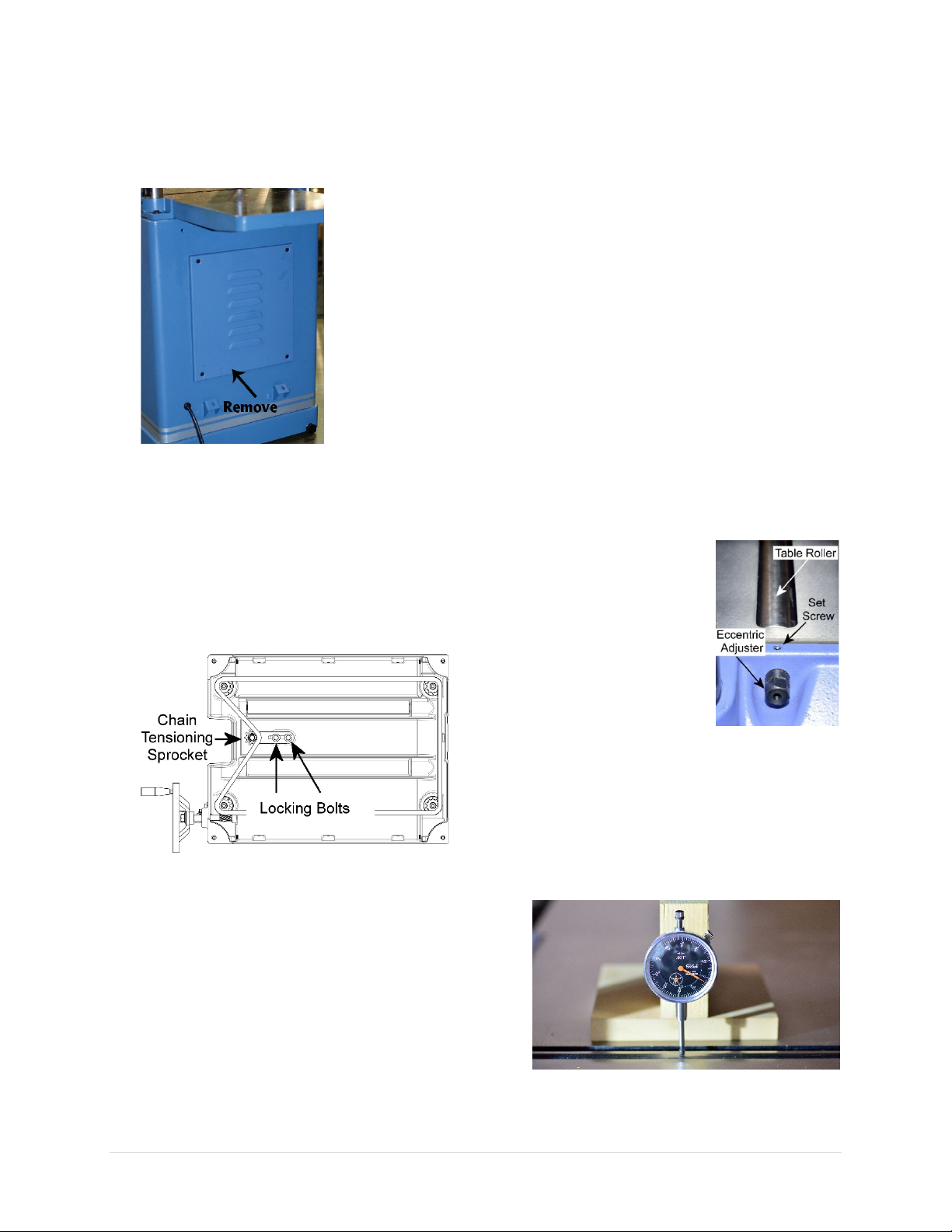
Adjust Table Chain Tension
1. Disconnect planer from power source!!
2. Remove motor access panel.
3. Loosen the two locking bolts for holding the
chain tensioner bracket in place.
IMPORTANT: Keep table chain tensioned
while loosening the locking bolt. If the chain
falls off from the sprockets, it can take a lot
of time to reinstall the chain and recalibrate
the planer.
Adjust Table Roller Height
Your planer is equipped with one table roller to
help feeding a workpiece through the planer.
There is no fixed rule for setting the exact
height of the table rollers, because each piece
of wood behaves differently. The acceptable
range of table roller height is: 0.002”- 0.005”
above the table.
As a general rule of thumb:
• Raise the roller when planing rough stock.
• Lower the roller when planing smooth
stock.
NOTICE: If the roller is set too high, the
workpiece will be more likely to have snipe on
the ends.
To adjust table roller height:
1. Disconnect planer from power source!!
2. Each end of the table
roller is equipped with a
set screw and an
eccentric adjuster.
Make sure height
adjustment is done on
both ends.
4. Push the chain tensioning sprocket against
the chain with moderate tension to remove
chain slack. Hold the sprocket in place, and
re-tighten the locking bolts.
5. Clean and lubricate the chain as needed.
6. Re-install motor access panel when
adjustments complete.
3. Loosen the set screws that hold the
eccentric adjusters.
4. Rotate the eccentric adjusters to change
roller’s height.
5. Use a dial indicator to verify the height is
the same side-to-side. Make fine
adjustments as needed.
6. Retighten the set screws to lock the
eccentric adjusters when adjustments
complete.
42 | Page Oliver Machinery 10014 Planer
Page 43
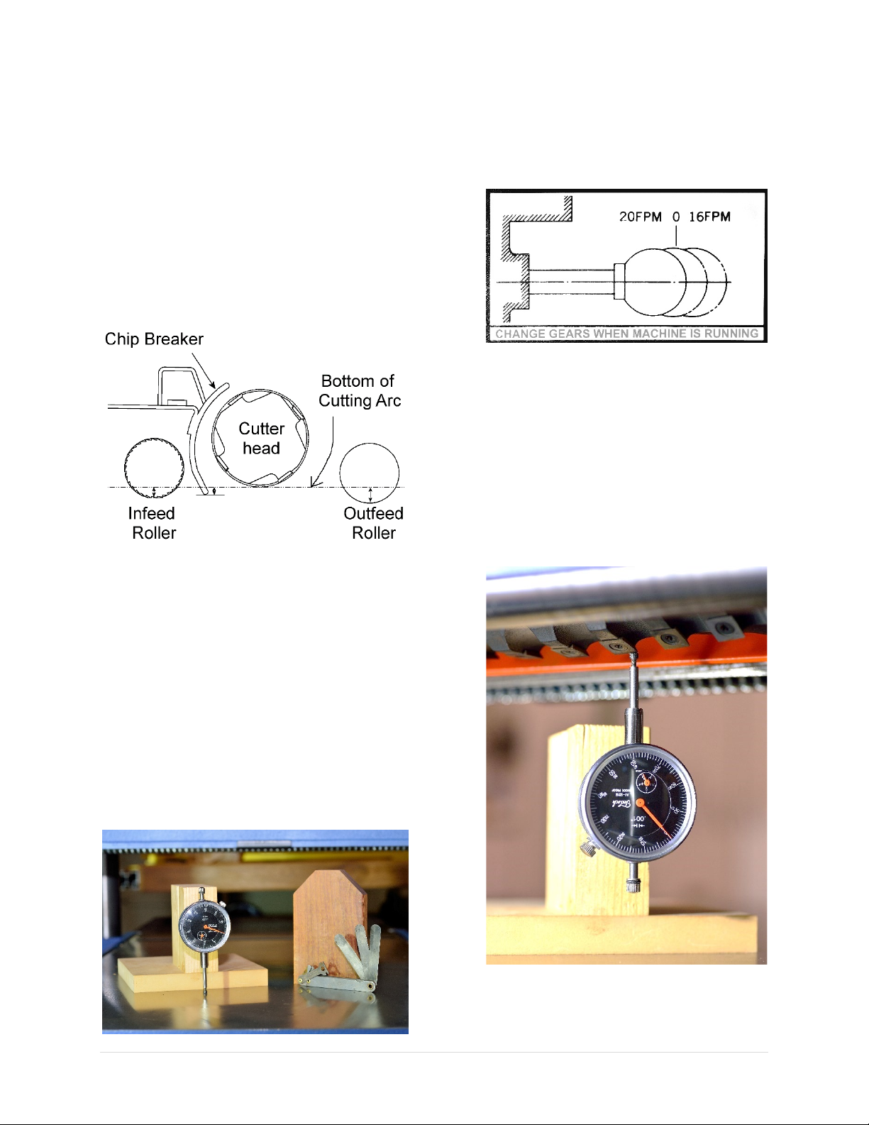
Adjust Cutterhead/Feed Roller Height Offset
The infeed/outfeed rollers pull the workpiece
through the planer. To ensure optimal
feeding/cutting performance, it is important to
ensure the height offsets between the
cutterhead and the feed rollers are correct.
The following diagram shows the height offset
between the cutterhead and various
components inside the headstock of the planer.
The feed rollers and chip breaker are installed
BELOW the lowest point of cutterhead.
*Diagram not drawn to scale
The height of the rollers and the chip breaker
has been pre-calibrated in the factory and
should not need further adjustments.
In case if adjustments are needed, you will need
a dial indicator with a sturdy stand. If a dial
indicator is not available, it is possible to make
the adjustments with a home-made gauge
block and a set of feeler gauges.
Clean the table and the rollers to remove any
accumulations before making adjustments.
Method 1: Using a Dial Indicator
1. Remove all tools from the planer.
2. Turn on the planer, wait until it reaches full
speed, then shift the feed rate control knob
to 0 FPM (Neutral) position.
3. Turn off planer. Disconnect planer from
power source!!
4. Remove the belt cover so you can rotate
the cutterhead with the drive belt.
5. Raise the headstock, fit the dial indicator
right below the cutterhead. Rotate the
cutterhead and use the dial indicator to
locate its lowest point. Using a flat bottom
tip for the dial indicator can make this task
easier.
6. Zero the dial indicator. Use this as the
reference point for measuring the offset
10014 Planer OLIVERMACHINERY.NET 43 | Page
Page 44

between the cutterhead and the feed
rollers.
44 | Page Oliver Machinery 10014 Planer
Page 45
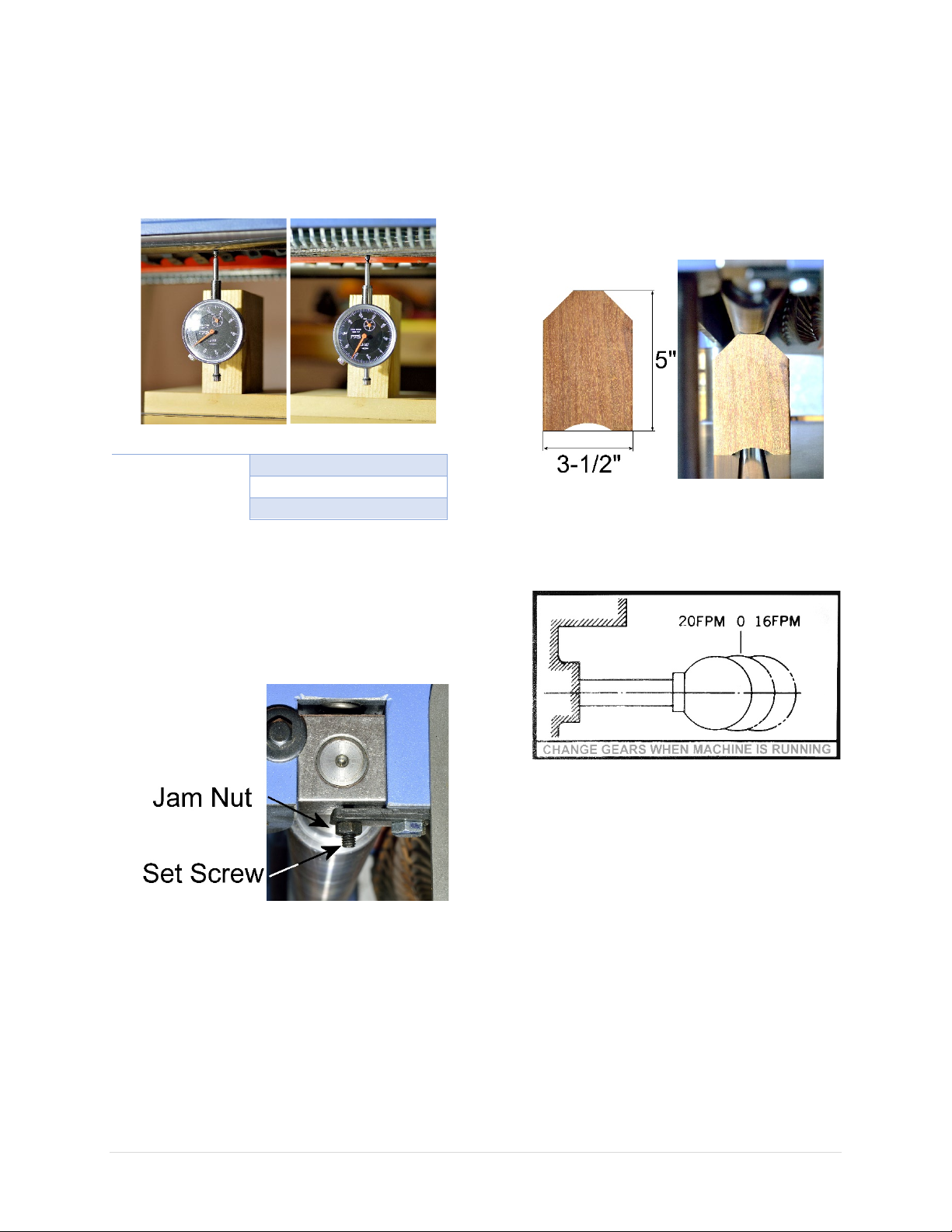
7. Move the dial indicator to the lowest point
Tolerance
Infeed Roller
0.020” - 0.027” below
Chip breaker
0.000” - 0.020” below
Outfeed Roller
0.024” - 0.031” below
of the feed rollers. The reading from the
dial indicator now shows the offset
between the cutterhead and the roller.
Made adjustments if the offset goes
beyond the tolerance listed below.
Method 2: Using Feeler Gauge
1. Using hardwood, build a gauge block similar
to this one below. The exact dimension is
not critical. Just make sure the bottom
clears the table roller. The top should be
chamfered for better tool access and
visibility.
2. Remove all tools from the planer.
8. To adjust the height of the feed rollers,
loosen the jam nuts on both ends of the
feed roller. Rotate the set screws to change
the height of the roller. Continue to
calibrate until the cutterhead-roller offset is
uniform across the entire feed roller.
9. When the correct height is set, hold the set
screws in place and re-tighten the jam nuts.
10. Re-install belt cover when adjustments
complete.
3. Turn on the planer, wait until it reaches full
speed, then shift the feed rate control knob
to 0 FPM (Neutral) position.
4. Turn off planer. Disconnect planer from
power source!!
5. Remove the belt cover so you can rotate
the cutterhead with the drivebelt.
10014 Planer OLIVERMACHINERY.NET 45 | Page
Page 46
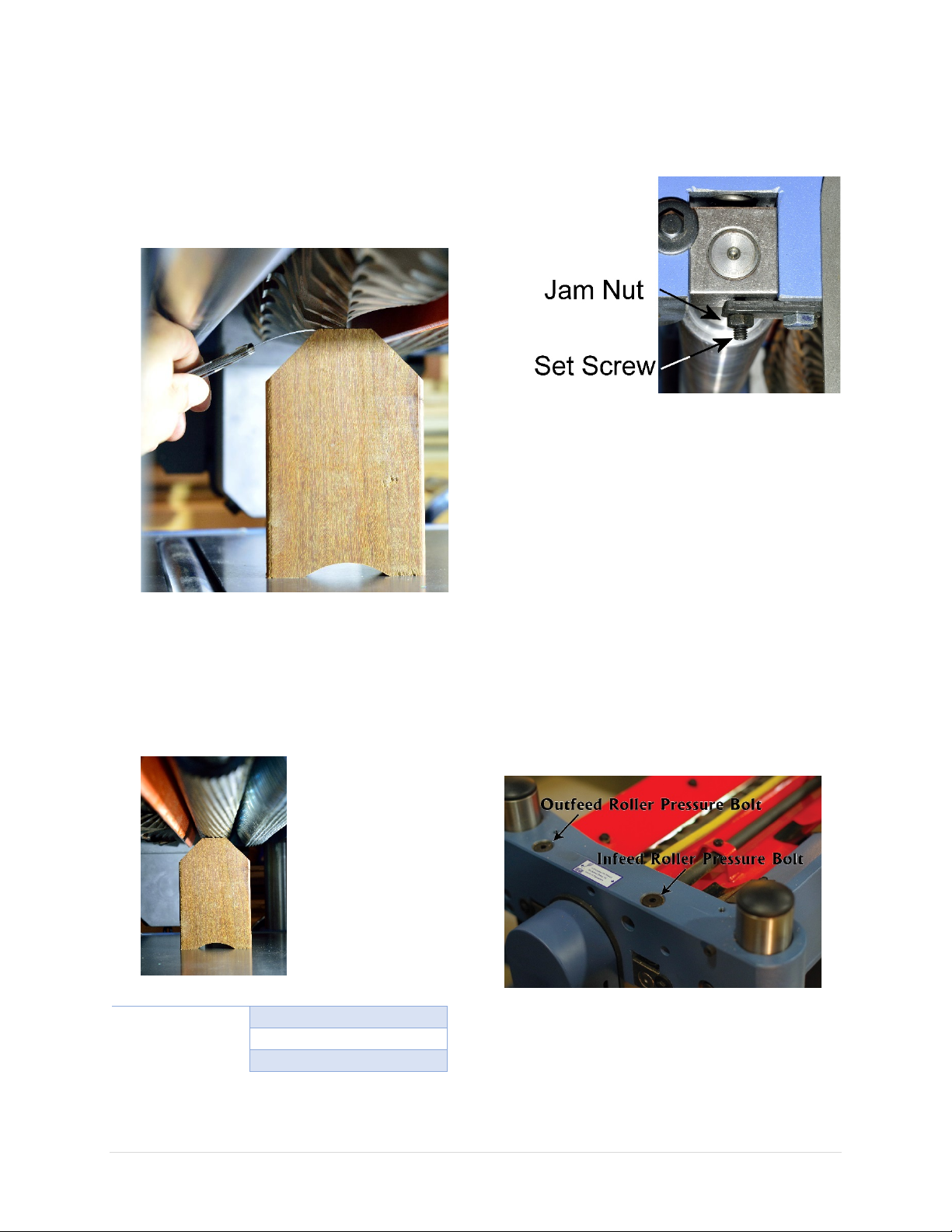
6. Raise the headstock, place the gauge block
Tolerance
Infeed Roller
0.020” - 0.027” below
Chip breaker
0.000” - 0.020” below
Outfeed Roller
0.024” - 0.031” below
below the cutterhead. For checking the
infeed roller’s offset, put the 0.020” feeler
gauge on top of the gauge block.
7. Lower the cutterhead until the lowest point
of the cutterhead barely touches the feeler
gauge.
8. Remove the feeler gauge and move the
gauge block under the infeed roller. The
gauge block should fit right under the
infeed roller if the height setting is perfect.
You may need to rotate the infeed roller to
find the lowest spot. Made adjustments
according to specifications as needed:
feed roller. Rotate the set screws to change
the height of the roller. Continue to
calibrate until the cutterhead-roller offset is
uniform across the entire feed roller.
10. When the correct height is set, hold the set
screws in place and re-tighten the jam nuts.
11. Repeat STEP 7-13 for the outfeed roller,
and use a 0.030” feeler gauge instead.
12. Re-install belt cover when adjustments
complete.
Adjust Feed Roller Tension
If your workpiece is slipping and not feeding
through the machine, increase the feed roller
pressure by turning the pressure bolts
clockwise with a hex wrench.
9. To adjust the height of the feed rollers,
loosen the jam nuts on both ends of the
46 | Page Oliver Machinery 10014 Planer
There is a pressure adjustment bolt on each end
of the feed rollers. Make sure the adjustments
are made on BOTH ends of the feed roller, so
even pressure is applied across the entire feed
roller.
Page 47
If the workpiece is damaged by the feed roller,
personal injuries.
reduce pressure.
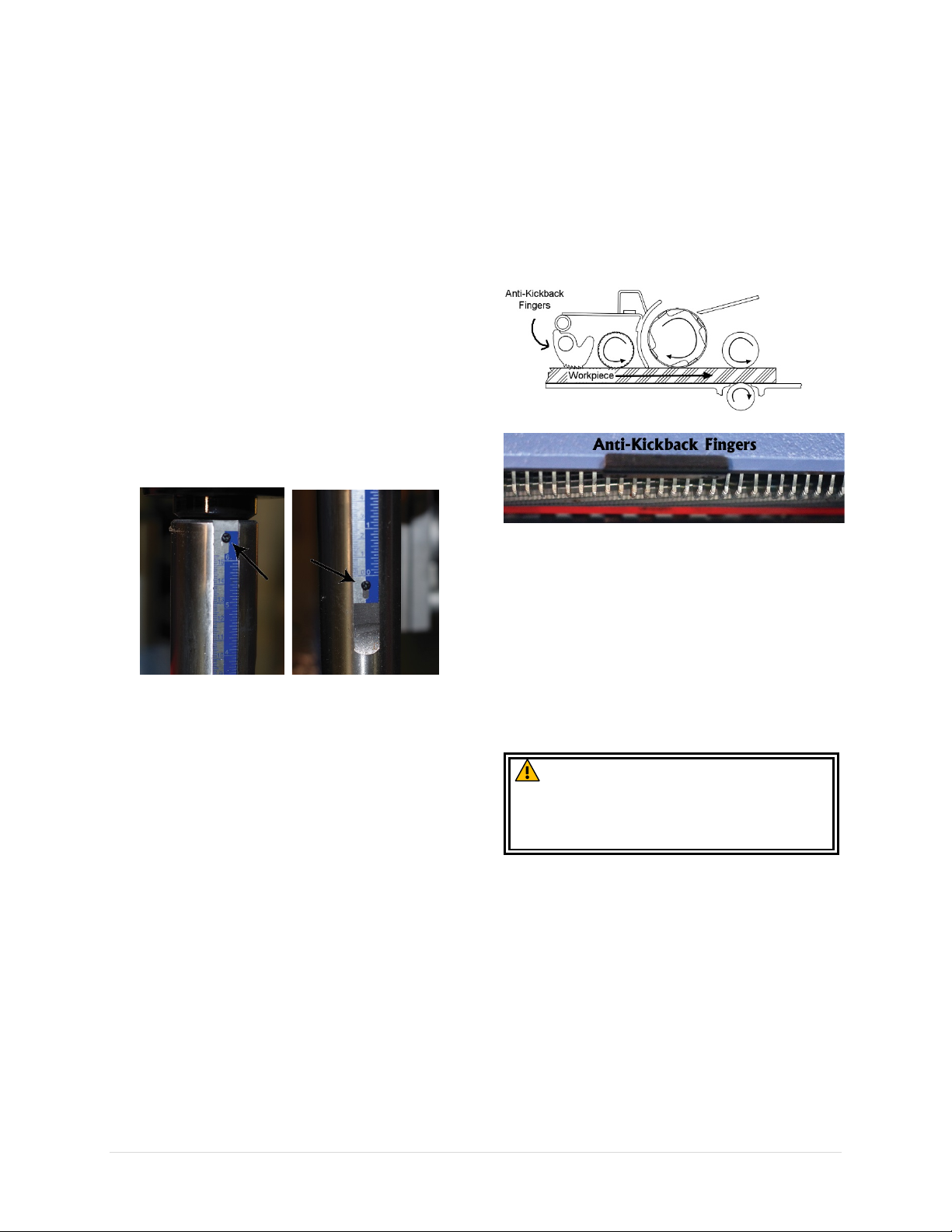
Adjust Cutterhead Height Scale
The cutterhead height scale is pre-calibrated at
the factory. It can be adjusted to accommodate
a different viewing angle, or if the scale is
shifted.
1. Prepare a piece of 2x4 with flat bottom for
calibration.
2. Using the digital readout, plane the board
down to 1-1/4” or 1”. Use a caliper to
measure the mid-section of the board for
thickness.
3. Loosen the top and bottom screws that
holds the scale in place.
4. Shift the scale so that the pointer is
pointing at the exact value as the thickness
of the board.
5. Re-tighten the screws when adjustments
complete.
Anti-Kickback Fingers Inspection
This planner is equipped with anti-kickback
fingers. Once engaged, the workpiece can only
move towards the cutterhead. This prevents
accidental kickbacks which can cause serious
injuries.
Inspect the anti-kickback fingers regularly to
ensure they can move freely, and that their
teeth are clean and are sharp enough to stop a
board from moving backwards. Clean and
lubricate with very light coat of SAE-30 machine
oil as needed.
Replace anti-kickback fingers if they are
damaged or worn.
CAUTION: Do not operate this planer
without functioning anti-kickback fingers.
Failure to comply can result in serious
10014 Planer OLIVERMACHINERY.NET 47 | Page
Page 48

Troubleshooting
Problem
Possible Cause
Possible Solution
Machine does not start.
Stop button is not
Turn the rim of the STOP button clockwise to
Machine is not
1. Make sure machine is plugged in, or power
Low voltage / current.
Have an electrician to check/repair the power
circuit.
Faulty switch/motor/
capacitor.
Contact customer service for further assistance.
Machine trips thermal
Machine is undersized
for the operation.
Reduce the depth of cut and/or feed rate.
Workpiece moisture
Only plane wood with moisture level below
Machine is jammed.
Inspect cutterhead and make sure it is not
Too much load on a
Make sure the power circuit is sized for this
Motor/capacitor issue.
Contact customer service for further assistance.
Machine stalls during
Machine is undersized
for the operation.
Reduce the depth of cut. Lower feed rate.
Dull cutters
Rotate/replace cutter inserts.
Belt slipping
Clean belt and the pulleys. Adjust belt tension.
Motor/capacitor issue.
Contact customer service for further assistance.
Machine stopped
Thermal overload
Hit STOP button to reset overload protection.
Chain jumps during
Loose chain.
Replace chain.
Misaligned sprockets.
Align sprockets.
Worn sprockets.
Replace sprockets and chains.
Digital readout not
functional.
Dead battery.
Replace battery.
protection / circuit
breaker, or blow fuses.
reset.
connected to a power
source.
level is too high.
reset. The stop button will pop up.
disconnect is at the ON position.
2. Check electrical panel for tripped circuit
breaker or blown fuse.
3. Ensure all electrical connections have good
contacts.
20%.
obstructed by woodchips. Check dust port and
headstock and clear blockages.
operation.
during operation.
operation.
circuit.
protection triggered.
machine. If the same circuit is shared, ensure
the circuit is sized to supply power for all items
in the circuit.
Wait for the machine to cool down. Reduce
depth of cut and feed rate before continue.
48 | Page Oliver Machinery 10014 Planer
Page 49

Problem
Possible Cause
Possible Solution
Unable to move feed rate
knob.
Machine is not running.
Only move feed rate knob while the
machine is running idle at full speed.
Feed rollers does not move
Gear box is in neutral.
Shift feed rate control knob to set feed rate
Workpiece does not feed
Low feed roller
pressure.
Adjust feed roller spring tension.
Incorrect feed roller
Adjust feed rollers height so the bottom of
Dirty planer table /
Clean table and rollers. Apply paste wax on
Belt slipping
Clean belt and the pulleys. Adjust belt
Stuck planer bed roller.
Clean and lubricate roller.
Machine vibrates
Damaged cutter
inserts.
Replace cutter inserts.
Machine stands on
uneven floor.
Reposition on flat, level surface.
Chip deflector is hitting
Move chip deflector 1/16”- 1/8” away from
cutterhead.
V-belt worn, slipping or
Clean belt and pulleys. Adjust belt tension.
Feed roller bushing
needs lubrication.
Lubricate bushings.
Bent pulley
Replace pulley.
Improper motor
Check and adjust motor mounting.
Loose components.
Tighten fasteners of the component.
Worn bearings
Contact customer service for assistance.
Uneven depth of cut side to
Cutterhead is not
table.
Adjust cutterhead-table parallelism.
Board thickness does not
measurement.
Cutterhead height scale
Adjust the scale.
when machine is running.
smoothly.
excessively or makes
unexpected noise.
height setting.
rollers.
to 16/20 FPM while machine is running idle
at full speed.
the rollers is below the lowest point of the
cutterhead.
Infeed Roller: 0.020” - 0.027” below.
Outfeed Roller: 0.024” - 0.031” below.
the table to reduce drag. Do not use silicon
lubrications on table top.
tension.
side.
match the scale’s
the cutterhead.
hitting belt cover.
mounting.
parallel with planer
is mispositioned.
Replace V-belt if it shows signs of aging.
Tolerance: Less than 0.005” side-to-side.
10014 Planer OLIVERMACHINERY.NET 49 | Page
Page 50

Problem
Possible Cause
Possible Solution
Workpiece came out
twisted.
Workpiece is twisted
Planer is not the tool to flatten a twisted
Feed/bed roller is not
cutterhead.
Adjust roller/table parallelism.
Excessive snipe
Extension tables slope
Adjust the extension tables to make them
parallel with the planer bed.
Long workpiece is not
supported properly.
Use auxiliary rollers to support long workpiece.
A small amount of
sometimes.
Add an extra 6” length on a workpiece for
End of workpiece
Aggressive depth of cut
for the wood type.
Reduce depth of cut.
Planing end grain.
Do not plane end grain. Use a drum sander
Chipping in workpiece
Damaged cutter.
Rotate/replace cutter insert.
Planing against/across
Avoid planing workpiece with knots. Plane along
To much material
removed in one pass.
Reduce feed rate / depth of cut.
Indentation in
Dirty rollers.
Remove all buildups on infeed, outfeed, and
Inefficient chip
Check dust collection system for suction.
Fuzzy looking finish.
Wood moisture content
Only process wood with less than 20% moisture
Dull cutter.
Rotate/replace cutter insert.
Some wood types tend
Adjust feed rate / depth of cut.
Glossy looking finish.
Dull cutter.
Rotate/replace cutter insert.
Cutting depth too
shallow.
Increase depth of cut.
Long line or ridges
length of board.
Chipped cutter.
Rotate/replace cutter insert.
Serrated marks on
workpiece.
Cutting depth too
shallow.
Increase depth of cut.
before the cut.
parallel with the
down.
workpiece. Flatten one side with a jointer before
proceeding with a planer.
chipping
surface.
workpiece surface.
sniping can happen
grain; or knots.
removal.
too high.
planing, and then trim off the ends.
instead.
the grain and perform downhill cut whenever
possible. Moisten problematic areas before
planing.
table rollers.
Adjust chip breaker and chip deflector.
content.
to have fuzzy grain.
running along the
50 | Page Oliver Machinery 10014 Planer
Use sharp cutters.
Page 51
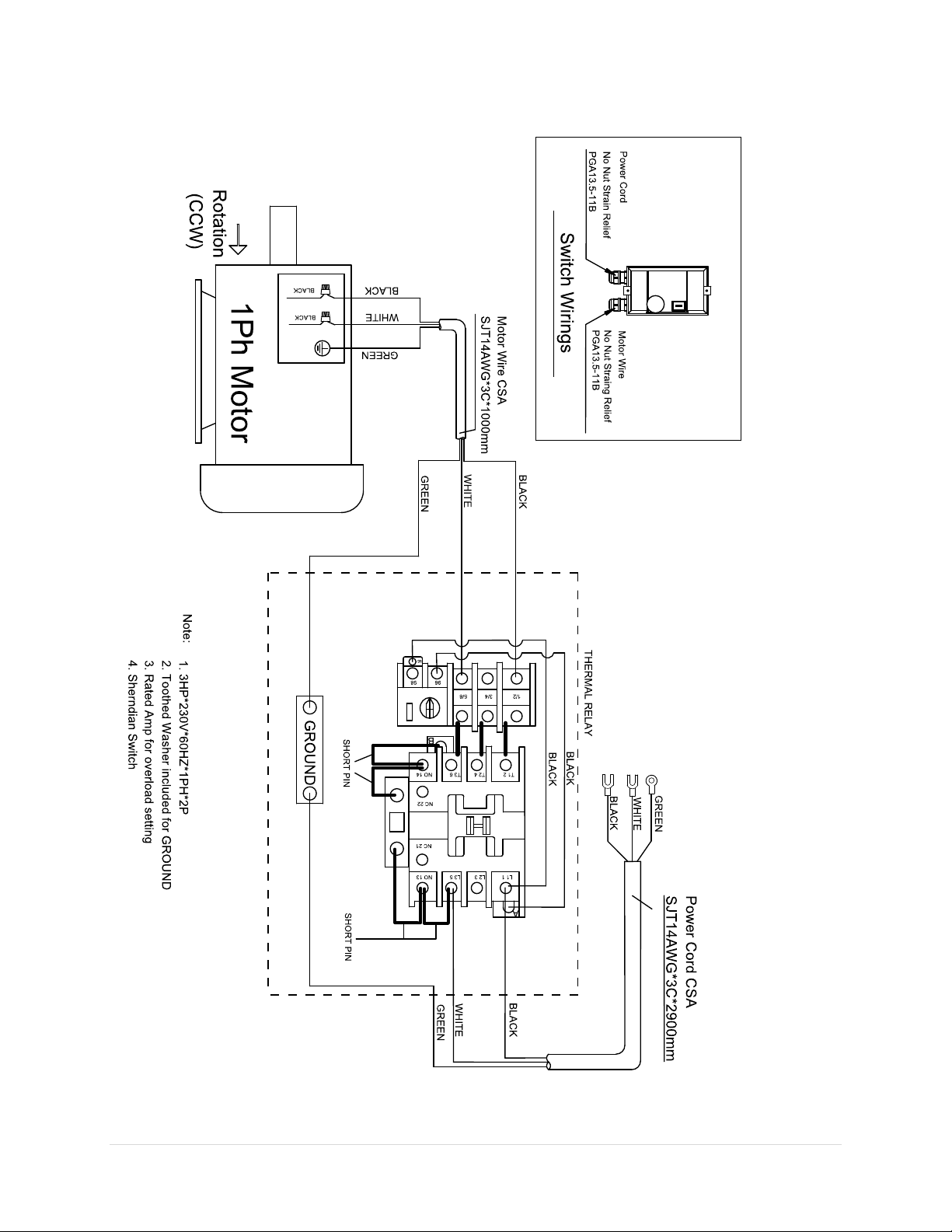
Wiring Diagram
10014 Planer OLIVERMACHINERY.NET 51 | Page
Page 52
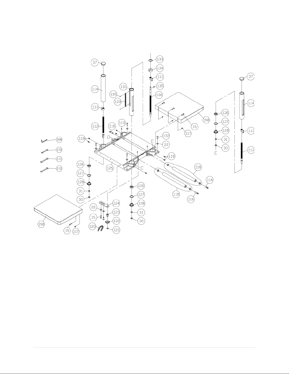
Parts List
Table Assembly
52 | Page Oliver Machinery 10014 Planer
Page 53
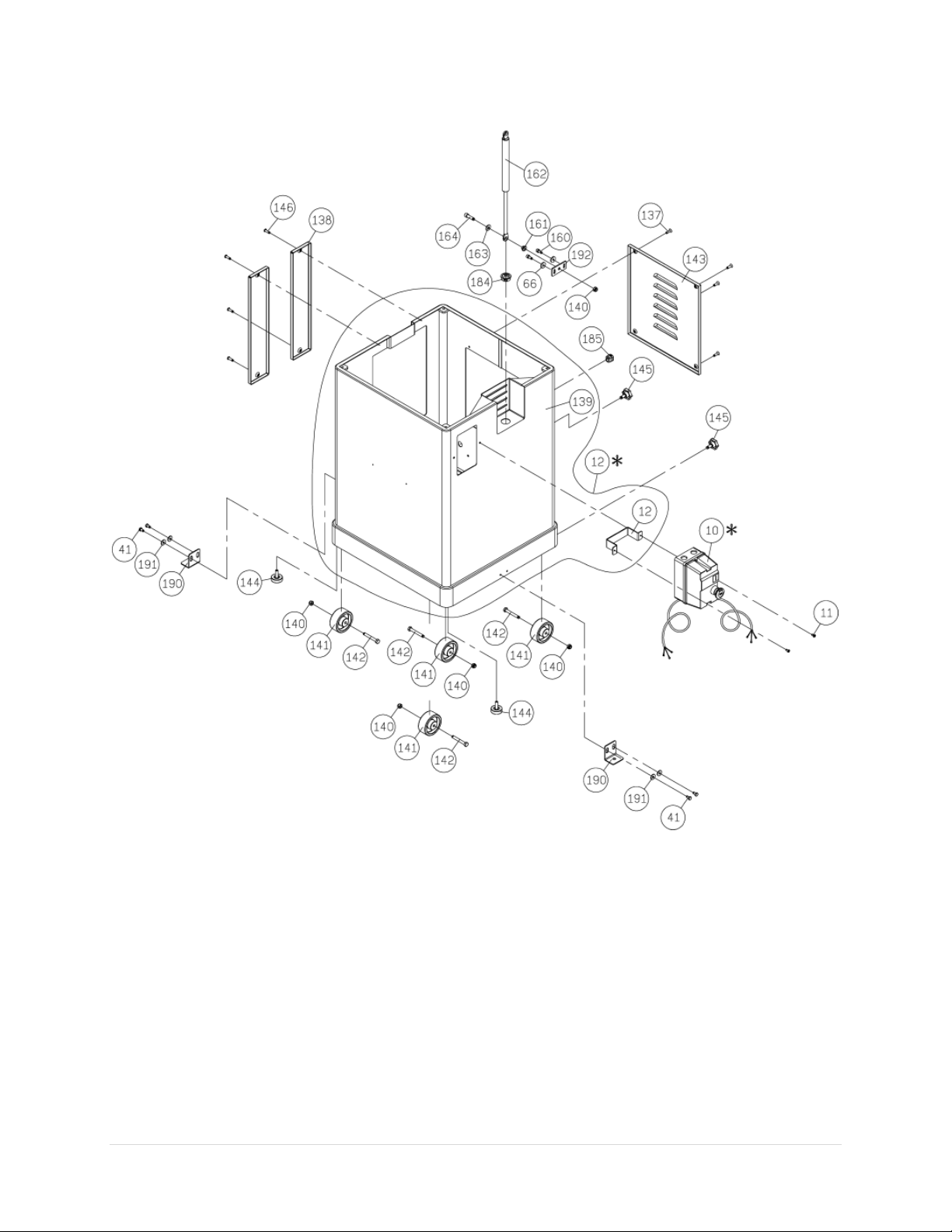
Cabinet Assembly
10014 Planer OLIVERMACHINERY.NET 53 | Page
Page 54
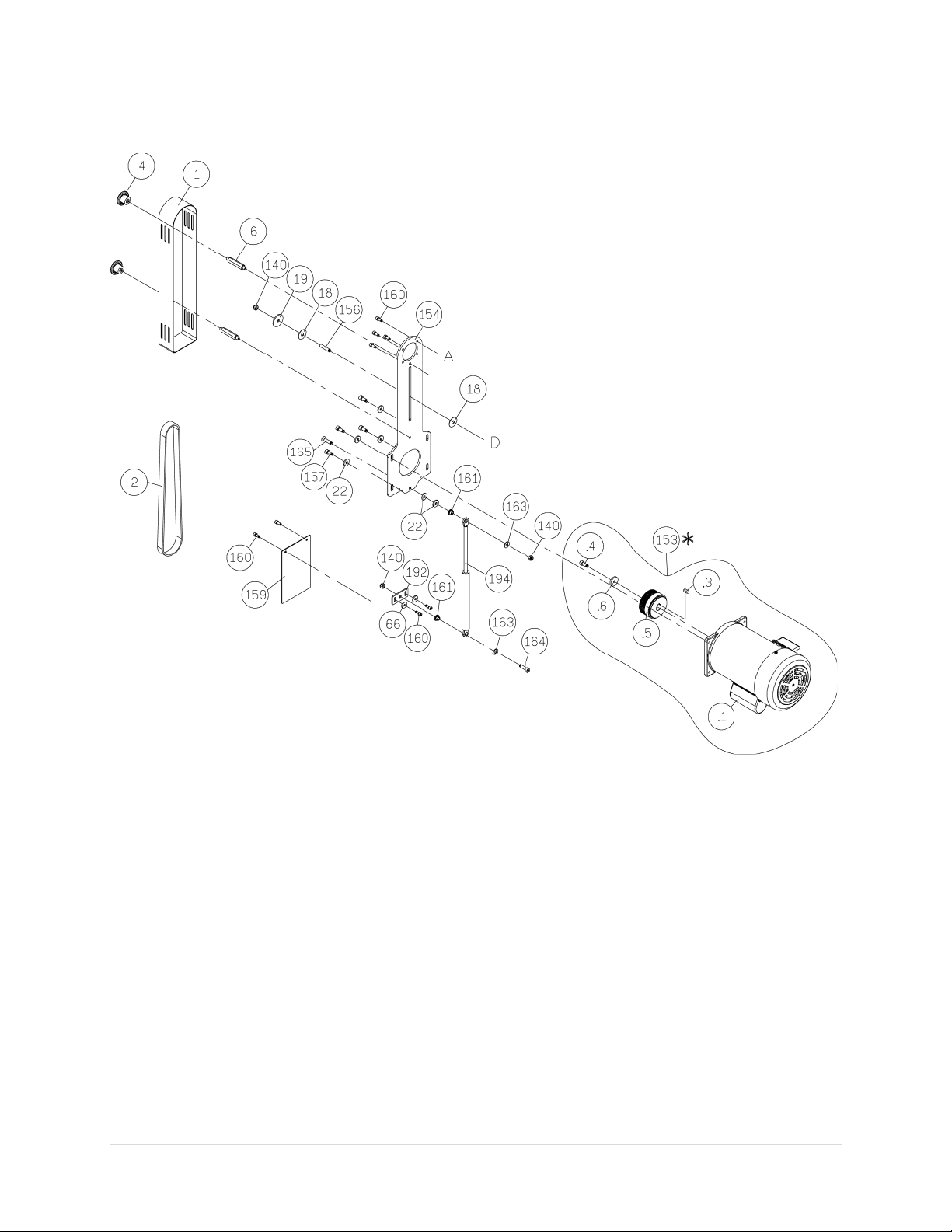
Motor Mount Assembly
54 | Page Oliver Machinery 10014 Planer
Page 55
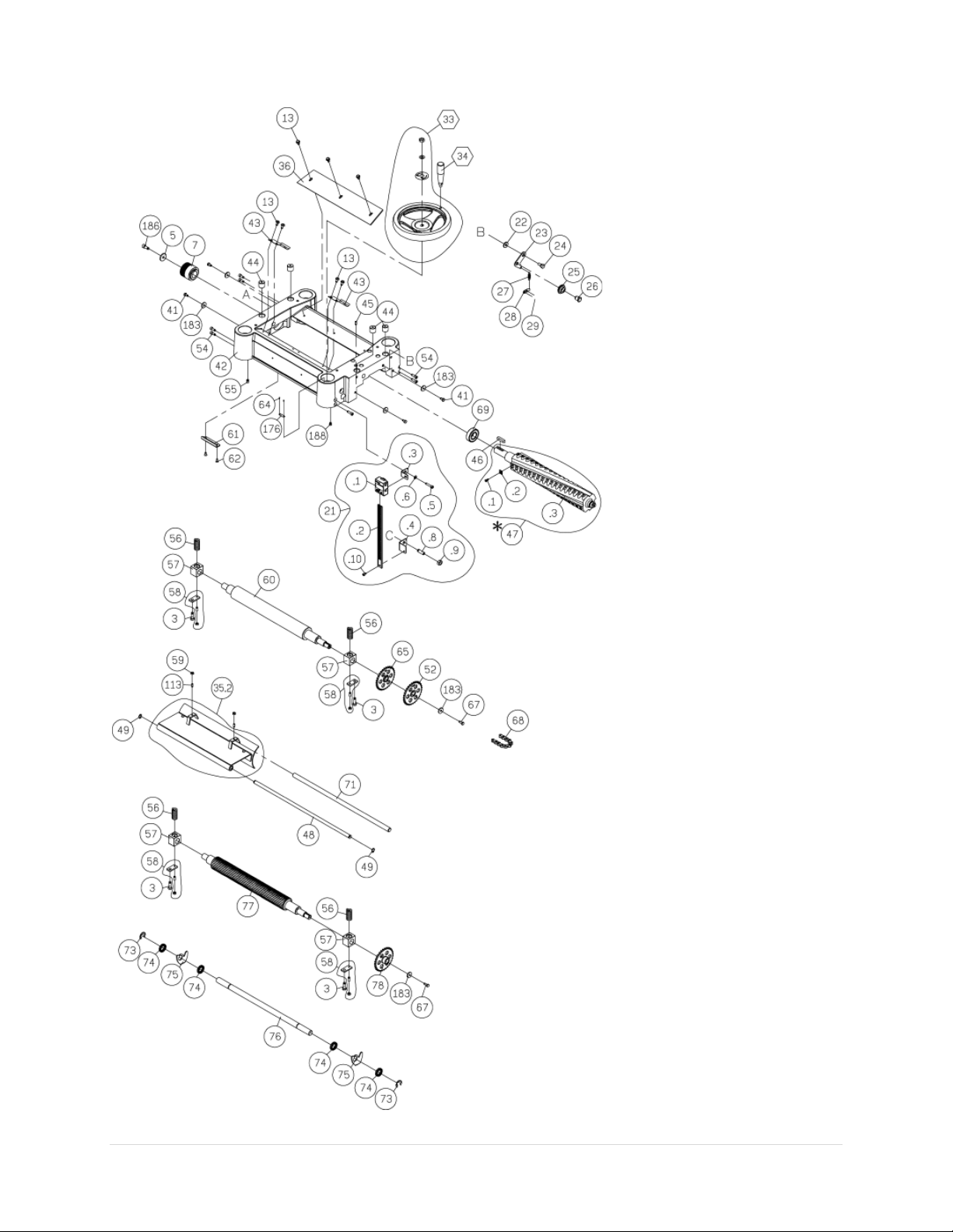
Headstock Assembly
10014 Planer OLIVERMACHINERY.NET 55 | Page
Page 56
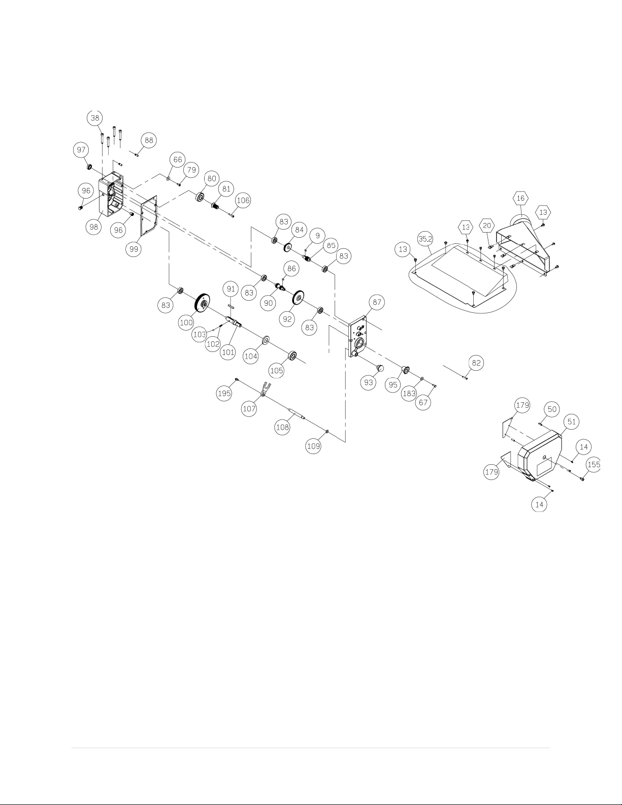
Gearbox Assembly and Dust Port Assembly
56 | Page Oliver Machinery 10014 Planer
Page 57

10014 Planer OLIVERMACHINERY.NET 57 | Page
Key
Part No.
Descriptions
Specification
Q'ty
1
174751-000
BELT GUARD
1
2
014316-000
POLY-V-BELT
400J-9
1 3 000003-104
HEX. SCREW
M8*1.25P*20
4
4
230118-000
KNOB
2
5
006001-043
FLAT WASHER
8.2*30*4.0t
1 6 380147-901
SPECIAL BOLT
2
7
381421-902
CUTTER HEAD PULLEY
1
9
012003-003
KEY
5*5*12
1
10
937986-001
MAGNETIC SWITCH ASSEMBLY
3HP*220V-240V*1PH
1
10.1
473003-065
CSA WIRE FOR MOTOR
SJT14AWG*3C*1000mm
1
10.2
473003-066
CSA WIRE FOR POWER SOURCE
SJT14AWG*3C*2900mm
1
11
000303-103
ROUND HEAD SCREW
M5*0.8P*10
2
12
174663-902
SWITCH PLATE
1
13
000902-102
HEX. SCREW W/WASHER
M6*1.0P*12
17
14
002001-704
SOCKET HEAD CAP SCREW
M4*0.7P*8
4
15
000003-105
HEX. SCREW
M8*1.25P*25
8
16
250345-615
DUST CHUTE
1
18
006007-140
FLAT WASHER
10.5*32*1.0t
2
19
006001-040
FLAT WASHER
8*30*3.0t
1
20
170813-901
RETAINING CLIP
3
21
924752-001
DRO SOLD AS ASSEMBLY ONLY
1
21.1
491142-000
DIGITAL READ OUT (Reference only)
1
21.2
950791-000
SENSOR STRIP ASSEMBLY (Reference
only)
1
21..3
174755-904
BRACKET-UPPER (Reference only)
1
21.4
174756-904
BRACKET-LOWER (Reference only)
1
21.5
000103-109
SOCKET HEAD CAP SCREW (Reference
only)
M6*1.0P*30
1
21.6
006001-022
FLAT WASHER (Reference only)
6.3*13*1.0t
1
21.8
000205-102
SET SCREW (Reference only)
M10*1.5P*30
1
21.9
008007-100
HEX. NUT (Reference only)
M10*1.5P(17B*8H)
1
21.1
000102-102
SOCKET HEAD CAP SCREW (Reference
only)
M5*0.8P*8
1
22
006001-041
FLAT WASHER
8.2*22*3.0t
13
23
170405-901
BRACKET
1
24
290039-901
SHAFT
1
25
130071-000
CHAIN TENSIONER
1
26
360349-901
CHAIN TENSIONER SHAFT
1
27
280050-000
SPRING
1
Page 58

58 | Page Oliver Machinery 10014 Planer
Key
Part No.
Descriptions
Specification
Q'ty
28
170406-901
HOOK
1
29
000103-102
SOCKET HEAD CAP SCREW
M6*1.0P*10
2
30
008008-100
HEX. NUT
M10*1.25P(17B*8H)
4
31
006001-078
FLAT WASHER
10.5*19*1.5t
4
33.1
240014-000
HAND WHEEL
1
33.2
008008-100
HEX. NUT
M10*1.25P(17B*8H)
1
33.3
006001-078
FLAT WASHER
10.5*19*1.5t
1
33.4
570887-000
INDICATOR LABEL
1
34.0
230114-906
HANDLE
1
35.1
170419-000
DUST HOOD
1
35.2
170410-019
CHIP BREAKER w/GASKET
1
36.0
250158-617
CHIP DEFLECTOR
1
37
250159-615
COLUMN CAP
3
38
000104-114
SOCKET HEAD CAP SCREW
M8*1.25P*50
4
41
000002-101
HEX. SCREW
M6*1.0P*12
8
42
051440-000
HEAD CASTING
1
43
270015-901
SPRING PLATE
2
44
380200-901
TENSION BOLT
4
45
000203-106
SET SCREW
M6*1.0P*16
1
46
012204-001
KEY
8*8*36
1
47
924751-001
HELICAL CUTTER HEAD ASSY
4SLOTS
1
47.1
038201-101
TORX SCREW
#10-32UNF*1/2"
52
47.2
P-15mm 4S
INSERT (SOLD IN BOX OF 10)
15*15*2.5t
52
47.3
924659-001
HELICAL CUTTER HEAD ONLY
1
48
361362-902
FIXING SHAFT
1
49
010003-000
RETAINING RING
STW-12
2
50
011004-102
SPRING PIN
6*20
2
51
251324-615
GEAR CASE COVER
1
52
150025-000
CHAIN SPROCKET
1
54
000103-106
SOCKET HEAD CAP SCREW
M6*1.0P*16
8
55
000204-103
SET SCREW
M8*1.25P*12
1
56
280051-000
SPRING
4
57
130039-000
BUSHING
4
58
923901-000
RETAINER PLATE ASSEMBLY
4
59
008005-100
HEX. NUT
M6*1.0P(10B*5H)
2
60
360383-000
OUTFEED ROLLER
1
61
170409-901
LIMIT PLATE
1
Page 59

10014 Planer OLIVERMACHINERY.NET 59 | Page
Key
Part No.
Descriptions
Specification
Q'ty
62
000402-104
FLAT HEAD SCREW
M5*0.8P*12
2
64
002301-201
RIVET
2*5 2 65
150027-000
CHAIN SPROCKET
1
66
006001-020
FLAT WASHER
6.2*20*3.0t
5
67
000002-103
HEX. SCREW
M6*1.0P*16
3
68
016306-000
CHAIN
#06B*63P
1
69
030209-002
BALL BEARING
6205
1
71
360351-000
SHAFT
1
73
010209-000
RETAINING RING
ETW-15
2
74
250160-615
SPACER
40
75
172281-905
ANTI-KICK BACK
39
76
360352-000
SHAFT
1
77
360353-000
INFEED ROLLER
1
78
150028-000
CHAIN SPROCKET
1
79
000103-103
SOCKET HEAD CAP SCREW
M6*1.0P*12
1
80
030208-002
BALL BEARING
6204
1
81
320196-000
GEAR
1
82
000103-108
SOCKET HEAD CAP SCREW
M6*1.0P*25
5
83
030106-002
BALL BEARING
6201
5
84
320197-000
GEAR
1
85
320160-000
SHAFT
1
86
012003-002
KEY
5*5*10
1
87
090350-920
GEARBOX COVER
1
88
360355-901
PIN 2
90
320205-000
SHAFT
1
91
012004-003
KEY
6*6*40
1
92
320198-000
GEAR
1
93
250372-615
KNOB
1
94
016303-000
CHAIN
#06B*47P
1
95
150008-000
CHAIN SPROCKET
1
96
043401-000
PLUG
PT1/4"-19
2
97
043608-000
OIL SEAL
TCX4 28*40*8
1
98
090349-920
GEARBOX
1
99
340012-615
GEARBOX GASKET
1
100
922351-001
GEAR ASSEMBLY
1
101
360357-000
SHAFT
1
102
280052-000
SPRING
1
Page 60

60 | Page Oliver Machinery 10014 Planer
Key
Part No.
Descriptions
Specification
Q'ty
103
017002-000
STEEL BALL
6mm
1
104
043505-000
OIL SEAL
SC25*47*6
1
105
030109-002
BALL BEARING
6204
1
106
002602-106
CAP LOCKING SCREW
M6*1.0P*25
1
107
070014-000
SHIFTING FORK
1
108
360358-901
SHAFT
1
109
043303-000
RETAINING RING
P12
1
111
130040-000
NUT
4
112
360359-000
COLUMN SHAFT
3
113
000203-104
SET SCREW
M6*1.0P*12
6
114
050277-000
COLUMN
3
116
360360-901
ECCENTRIC SHAFT
4
117
000204-105
SET SCREW
M8*1.25P*20
6
118
921209-001
ROLLER W/BALL BEARING (608)
2
119
000205-101
SET SCREW
M10*1.5P*12
8
120
016220-000
CHAIN
Z410*134P
1
121
010006-000
RETAINING RING
STW-15
1
122
150009-000
CHAIN SPROCKET
1
123
360362-901
SPROCKET SHAFT
1
124
170413-901
CHAIN TENSIONER BRACKET
1
125
051409-000
BASE CASTING
1
126
030003-001
BALL BEARING
6202
4
127
010103-000
RETAINING RING
RTW-35
4
128
150010-000
CHAIN SPROCKET
4
129
570888-000
SCALE
1
130
000301-101
ROUND HEAD SCREW
M3*0.5P*6
2
131
050279-000
MAIN COLUMN
1
132
000003-106
HEX. SCREW
M8*1.25P*30
4
133
010104-000
RETAINING RING
RTW-38
1
134
130041-000
BUSHING
1
135
012002-007
KEY
4*4*20
1
136
360364-000
ELEVATING SCREW
1
137
000403-104
FLAT HEAD SCREW
M6*1.0P*20
4
138
174577-000
COVER
2
139
174752-000
STAND
1
140
008306-100
HEX. LOCK NUT
M8*1.25P(13B*9H)
9
141
250399-615
WHEEL
4
Page 61

10014 Planer OLIVERMACHINERY.NET 61 | Page
Key
Part No.
Descriptions
Specification
Q'ty
142
000003-316
HEX. SCREW
M8*1.25P*60
4
143
170445-000
STAND ACCESS PANEL
1
144
230049-000
FOOT
2
145
004001-101
KNOB
5/16"-18NC*3/4"
2
146
000801-104
ROUND HEAD HEX SCREW
M6*1.0P*20
4
153.1
603160-008
MOTOR
3HP*220-240V*60HZ*1PH
1
153.3
012206-002
KEY
6*6*18
1
153.4
002601-107
CAP LOCKING SCREW
M8*1.25P*25
1
153.5
381422-902
MOTOR PULLEY
1
153.6
006001-043
FLAT WASHER
8.2*30*4.0t
1
154
174754-902
MOTOR BRACKET
1
155
000104-113
SOCKET HEAD CAP SCREW
M8*1.25P*45
1
156
000204-109
SET SCREW
M8*1.25P*40
1
157
001803-102
CAP SCREW W/SPRING WASHER
M8*1.25P*20/8.2*13.7
4
158
050429-000
EXTENSION WING
2
159
174753-000
PLATE
1
160
001802-101
CAP SCREW W/SPRING WASHER
M6*1.0P*16/6.5*10.5
10
161
361323-902
BUSHING
3
162
660291-000
GAS CYLINDER
35kgf
1
163
006001-054
FLAT WASHER
8.5*20*2.0t
3
164
000104-110
SOCKET HEAD CAP SCREW
M8*1.25P*30
2
165
000704-103
PAN HEAD SCREW
M8*1.25P*35
1
168
040004-000
HEX WRENCH (Local Purchase)
4mm
1
170
174569-904
COMBO WRENCH (Local Purchase)
10*13
1
171
040204-000
COMBO WRENCH (Local Purchase)
12*14
1
172
040206-000
COMBO WRENCH (Local Purchase)
17*19
1
179
174659-902
SIDE COVER GUARD
2
183
006001-021
FLAT WASHER
6.2*22*3t
7
184
021802-000
RELIEF BUSHING
NB-2430
1
185
020004-000
STRAIN RELIEF
SB8R-1
1
186
002601-107
CAP LOCKING SCREW
M8*1.25P*25
1
188
000102-101
SOCKET HEAD CAP SCREW
M5*0.8P*6
1
190
174711-000
SHIPPING PLATE
2
191
006001-036
FLAT WASHER
6.7*19*2.0t
4
192
174769-000
ADJUSTABLE BRACKET
2
194
660298-000
GAS CYLINDER
45kgf
1
195
029502-201
HEX. SCREW W/LOCK WASHER
M6*1.0P*12
1
Page 62

Date
Task
Operator
Maintenance Record
62 | Page Oliver Machinery 10014 Planer
Page 63

Notes
10014 Planer OLIVERMACHINERY.NET 63 | Page
Page 64

Warranty and Service
Oliver makes every effort possible to assure that its equipment meets the highest possible standards of
quality and durability. All products sold by Oliver are warranted to the original customer to be free from
defects for a period of 2 (two) years on all parts, excluding electronics and motors, which are warranted
for 1 year. Oliver’s obligation under this warranty shall be exclusively limited to repairing or replacing (at
Oliver’s option) products which are determined by Oliver to be defective upon delivery F.O.B. (return
freight paid by customer) to Oliver, and on inspection by Oliver. This warranty does not apply to defects
due, directly or indirectly, to misuse, abuse, negligence, accidents, unauthorized repairs, alterations,
lack of maintenance, acts of nature, or items that would normally be consumed or require replacement
due to normal wear. In no event shall Oliver be liable for death, personal or property injury, or damages
arising from the use of its products.
64 | Page Oliver Machinery 10014 Planer
Page 65

Oliver Machinery is always adding new Industrial Woodworking products to the line.
For complete, up-to-date product information, visit us online at:
WWW.OLIVERMACHINERY.NET
or call toll free 1-800-559-5065
** SAVE THIS MANUAL FOR FUTURE REFERENCES. **
 Loading...