

Page 1
MINIBOT
assembly guide
document revision 2, October 2019
www.olimex.com
Page 2

Board features
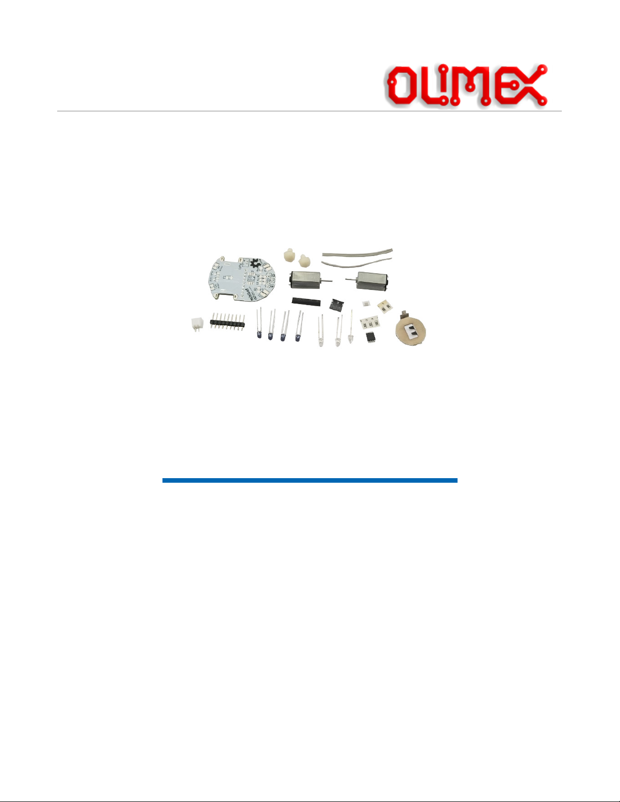
Minibot is an Open Source Hardware kit that produces a small robot with two motors and four
photo sensors. Assembling this kit requires soldering! The board can be programmed to
escape labyrinths or follow a line. The chip is pre-programmed with follow “the line” example.
You can see it in action here:
https://www.youtube.com/watch?v=u1omfYXurb0
All documents and sources can be found at the following GitHub address:
https://github.com/OLIMEX/Minibot
• IMPORTANT! This board arrives as a kit! Soldering required!
• IMPORTANT! Soldering tools are not included in the kit!
• IMPORTANT! This design has no USB connector! Additional hardware might be
required to establish USB connection!
• IMPORTANT! The kit comes without a battery, it should be purchased separately!
Page 3
Schematic
Page 4
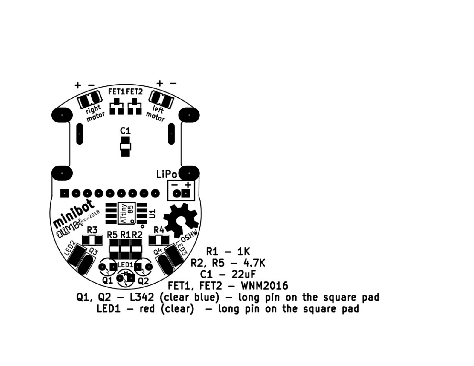
Component locations and assembly
Page 5
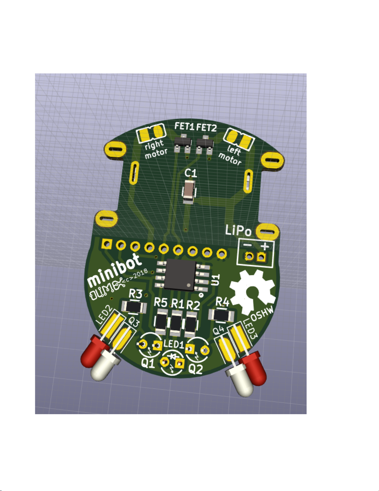
Assembly notes:
LED2, LED3 and Q3, Q4 are soldered aside.
Page 6
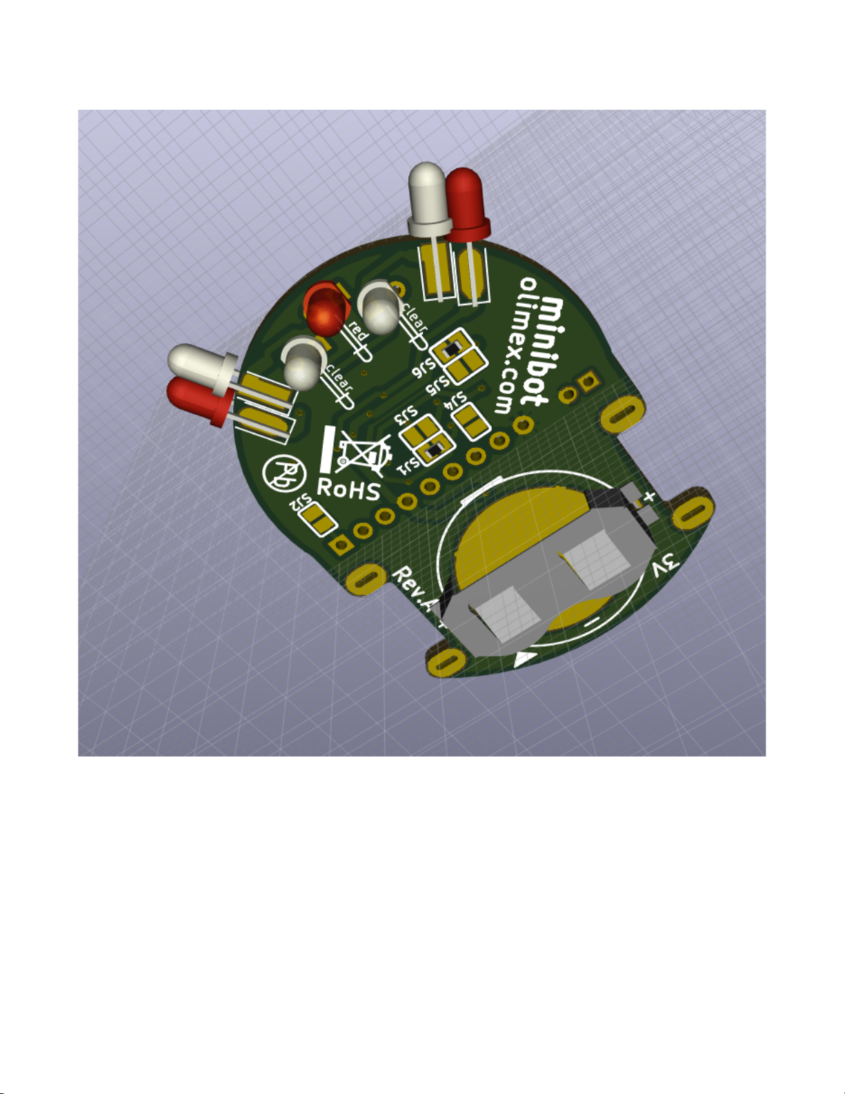
Q1, Q2, LED1 are soldered at the bottom
Page 7
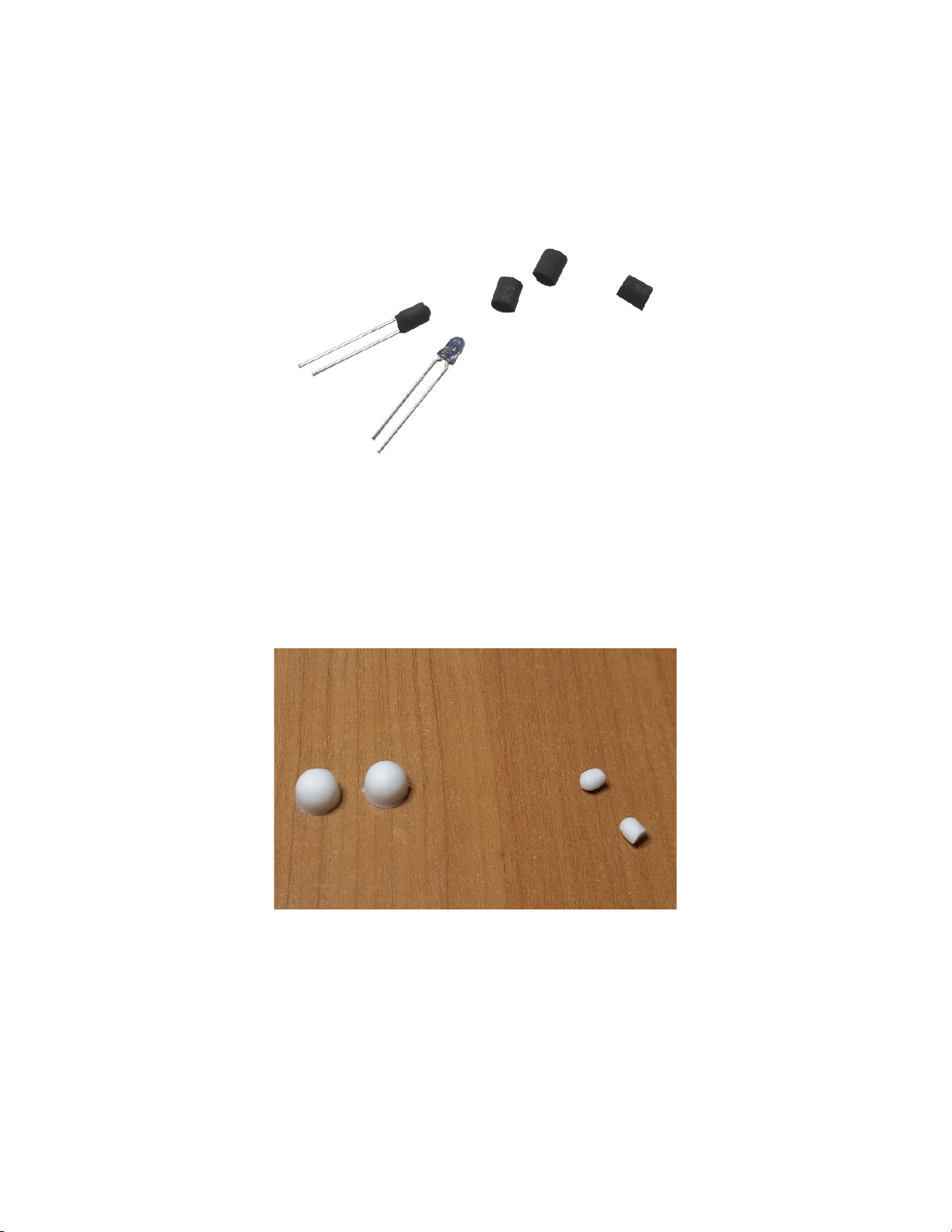
There is thermo shrinking tube in the kit – please cut in four and use each part to shield the
four photo sensors, so they receive light only from the top and not from aside. After placing
the thermo shrinking tube over a photo sensor heat it moderately so it shrinks:
In the kit there are two rubber pads which can be used as vehicle tyres on each motors. We
suggest to cut and use the smaller rubber pads as tyres, using the bigger pads will make
robot faster but also not very stable.
Page 8
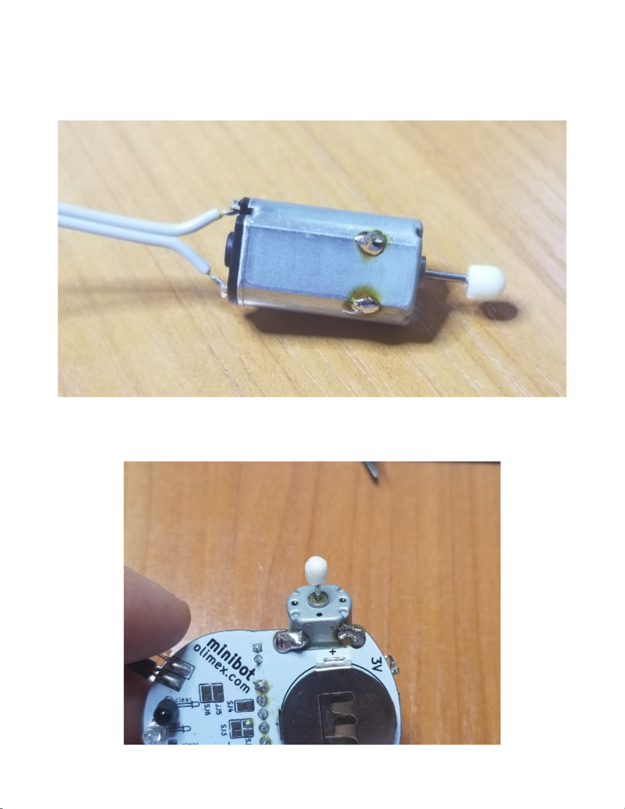
Prepare the motors for soldering to the board by tinning two dots on their body as shown on
this picture:
Then solder it at angle as seen in these pictures, note polarity – the motor has + and –
marked on the body:
Page 9
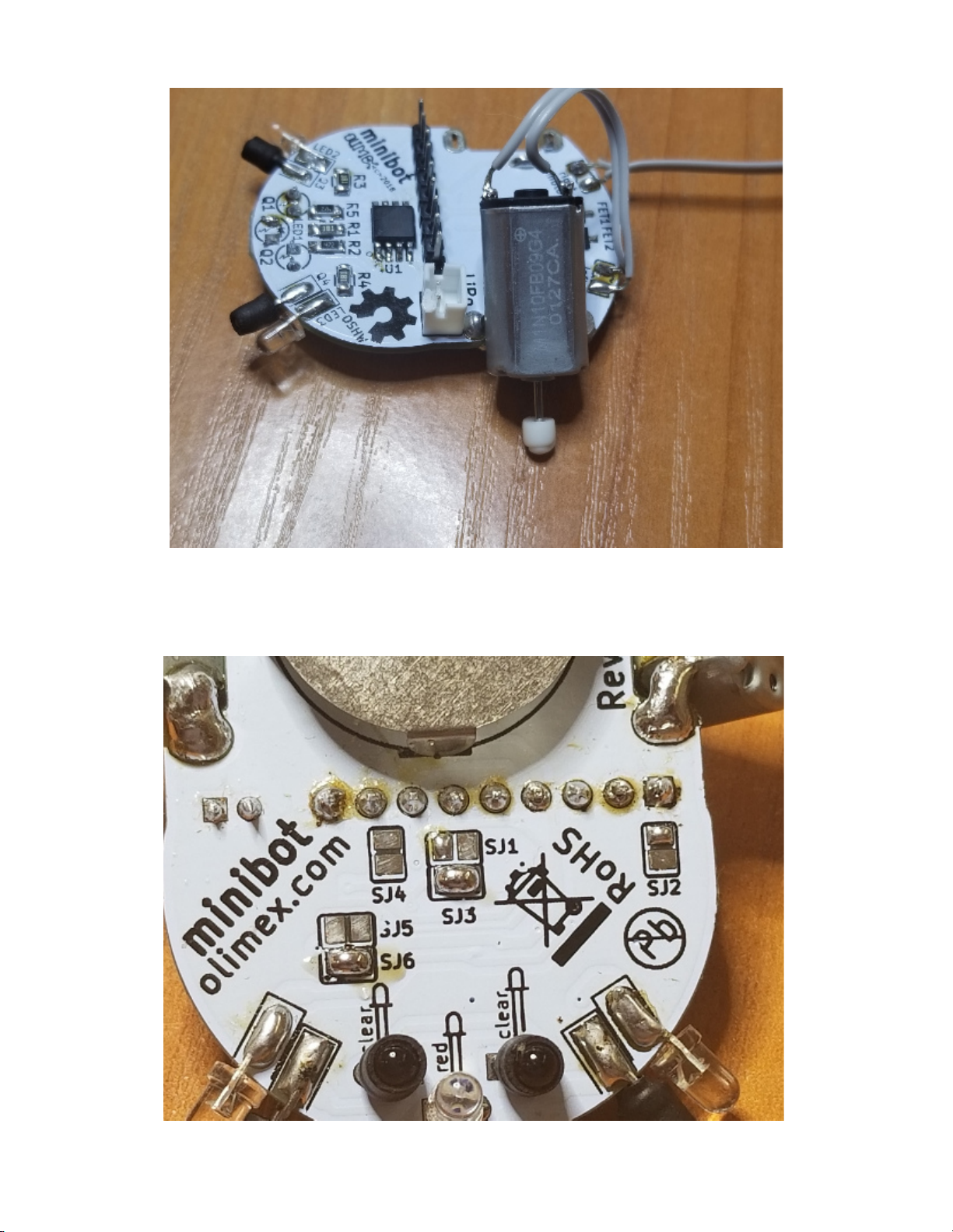
At the bottom side there are two solder jumpers SJ3 and SJ5 to be closed with solder joint:
Page 10
Power supply
3V Lithium battery may be used to power the robot, but we do recommend Li-Po 3.7V battery
like https://www.olimex.com/Products/Power/BATTERY-LIPO250mAh/ as it may be re-
charged and re-used. The battery is not included in the kit.
Programming the board
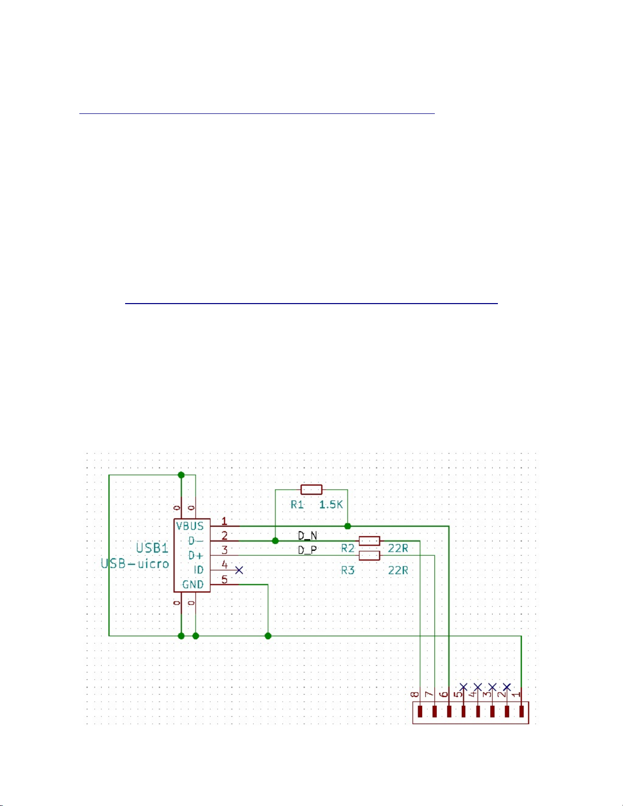
The board has no USB connector so you need to use the EXT1 header to access the required
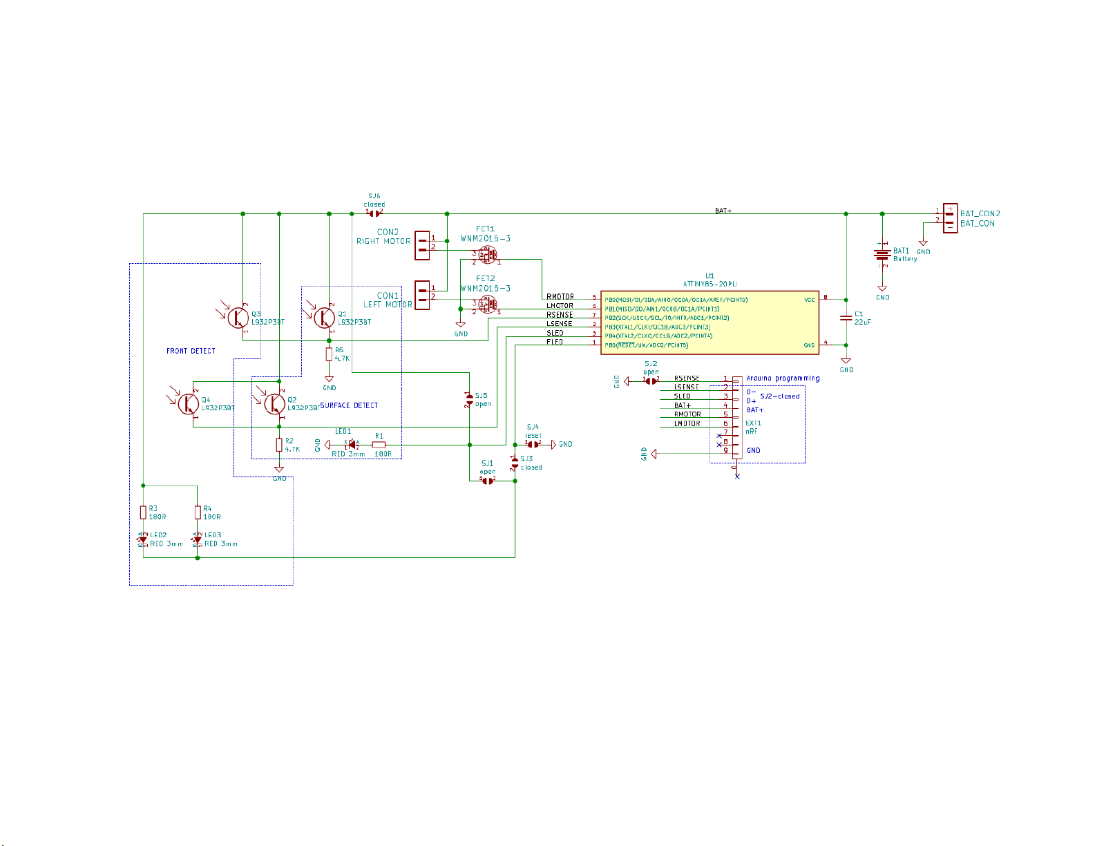
data signals D- and D+ and also the power signals VBUS and GND. Refer to the schematic
(either stand alone or the one in the beginning of this document) to see it very clear.
We use a small extension board with battery charger and micro USB connector for the task –
we attach it to the EXT1 connector, it is called MINIBOT-charger and the design can be seen
here:
https://github.com/OLIMEX/Minibot/tree/master/HARDWARE/charger
The design of the charger shows how a micro USB connector can be soldered. You might
want to search for a cable that has male USB connector at one end, and free wires at the
other end. It would be nice if the cable description also says which cable which signals is. If
you can't find such a cable you would need to cut one I guess. Then use D-, D+, BAT+, and
GND from the EXT1 connector. This is not sufficient though, you need to also connect D- to
VBUS via 1.5K Ohm resistor, as seen in the schematic of the *MINIBOT-charger* board, 22R
Ohm on the data lines are also a nice protection touch. For this you might want to use a
breadboard and jumper wires if you don't want to solder.
Page 11

Important! Trace carefully the pins! Whether it is 8 pins or 9 pins!
Important! Remember to disconnect the battery when you have established USB
connection programming! Else there will be short-circuit between the 5V coming from
the USB port and the battery.
Page 12
Software installation
All instructions below are for Ubuntu, but Windows installation is similar:
1. Download latest Arduino from www. arduino.cc
2. Extract the archive to your Home directory. Run terminal and go to arduino directory and
execute arduino script as superuser
$ sudo ./arduino
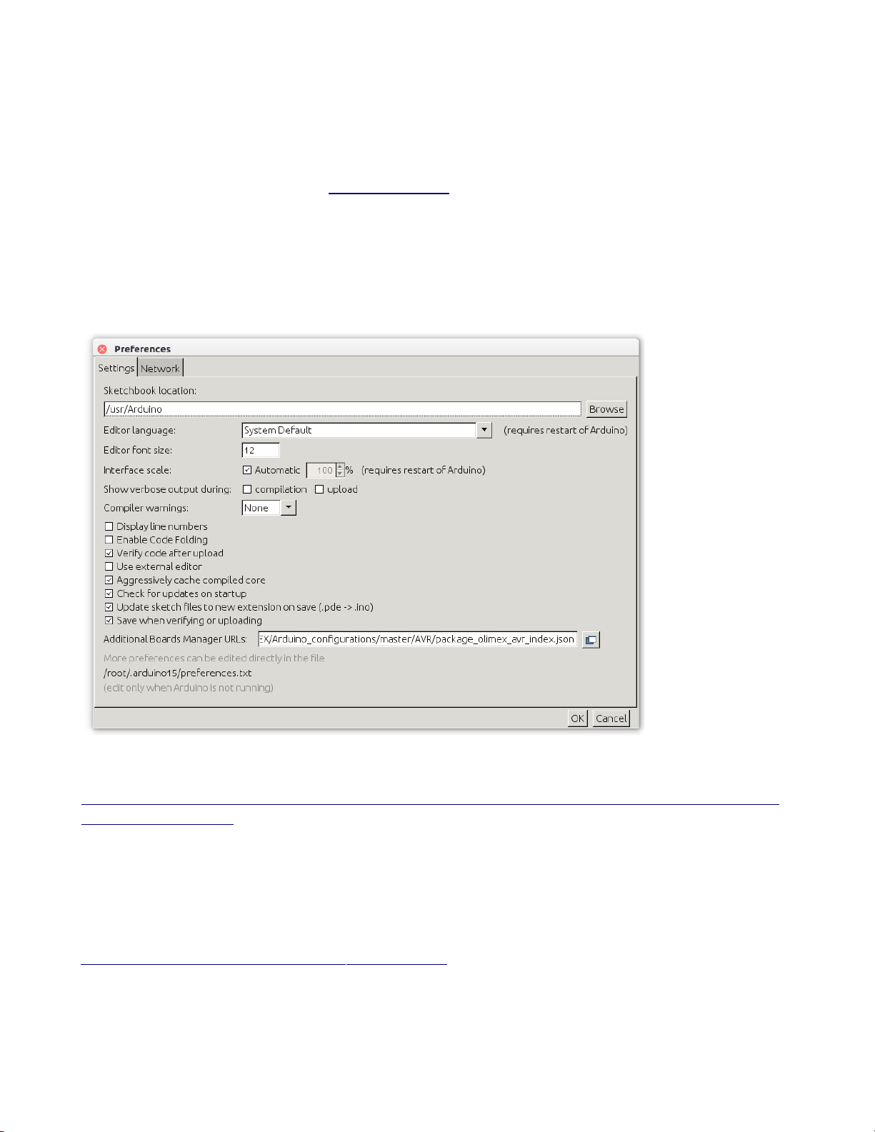
2. From File menu select Preferences:
In Additional Boards Manager URLs paste this:
https://raw.githubusercontent.com/OLIMEX/Arduino_configurations/master/AVR/package_oli
mex_avr_index.json
Then from menu Tools → Board → Boards Manager select OLIMEX AVR boards: then select
Olimexino-85 as Board.
From GitHub you can download the software examples:
https://github.com/OLIMEX/Minibot /SOFTWARE
Page 13

Revision History
1.0 initial
2.0 added a lot of information about the USB and the battery
 Loading...