

Page 1
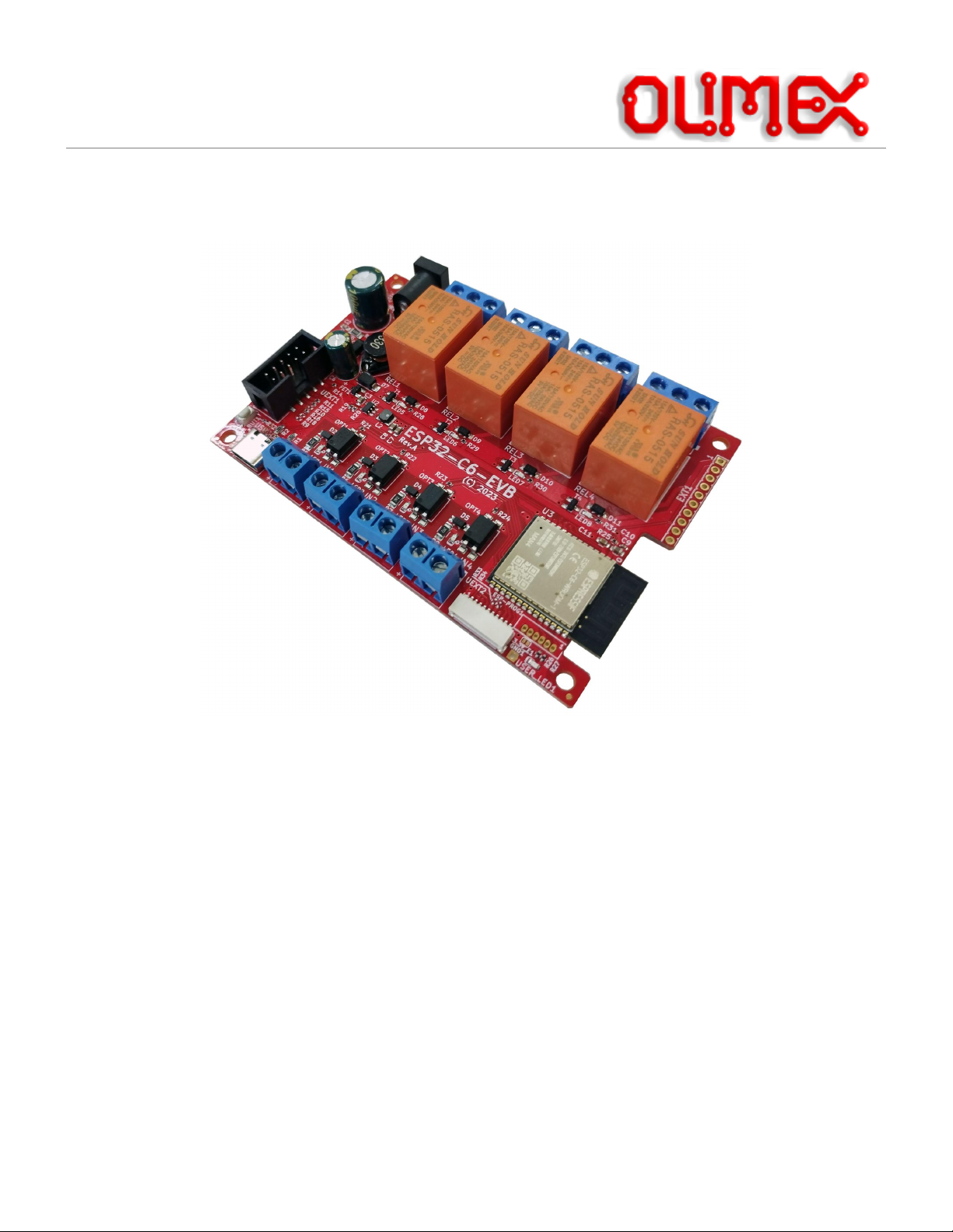
ESP32-C6-EVB
User Manual
Revision 2.0 June 2024 www.olimex.com
1
Page 2

Table of Contents
INTRODUCTION...............................................................................................................................................3
What is ESP32-C6-EVB?...............................................................................................................................3
ESP32-C6-EVB board features......................................................................................................................4
Order codes and links for ESP32-C6-EVB and accessories:..........................................................................5
ESP32-C6 reference documents:....................................................................................................................6
HARDWARE.......................................................................................................................................................7
ESP32-C6-EVB layout...................................................................................................................................7
ESP32-C6-EVB schematic.............................................................................................................................8
ESP32-C6-EVB power supply and consumption:........................................................................................10
EXT1 connector (GPIO)...............................................................................................................................11
UEXT connectors..........................................................................................................................................12
Relays............................................................................................................................................................13
Inputs............................................................................................................................................................13
User LED and button BUT1.........................................................................................................................13
ESP32-PROG header....................................................................................................................................14
Jumper 3.3V_E1...........................................................................................................................................14
SOFTWARE......................................................................................................................................................15
First time start up or how to program the board...........................................................................................15
Olimex tested firmware and examples..........................................................................................................15
DOCUMENT REVISION.................................................................................................................................16
2
Page 3

INTRODUCTION
What is ESP32-C6-EVB?
ESP32-C6-EVB is a WIFI-enabled and Bluetooth-enabled development board that also has free GPIOs,
analog, and digital inputs and outputs on boxed connector and more.
ESP32-C6-EVB uses ESP32-C6, Espressif’s first Wi-Fi 6 (IEEE 802.11ax) module. It integrates 2.4 GHz
Wi-Fi 6, Bluetooth 5 (LE), and the 802.15.4 low-rate wireless personal area network (LR-WPAN).
ESP32-C6-EVB is perfect for stand-alone usage but can also be attached to any existing hardware project to
augment it with with 2.4GHz Wi-Fi 6 and Bluetooth LE 5.3 capabilities.
ESP32-C6-EVB requires only a USB cable for programming and powering; the board is equipped with USB
type C connector, the type of cable used for charging most mobile phones.
ESP32-C6-EVB is an Open Source Hardware project, all CAD source files are available at our GitHub
repositories. Files are released under CERN Open Hardware License Version 2 – strongly reciprocal and
allows users to learn, study, edit, modify, manufacture, and sell same, or derivative products based on these
designs. The only requirements is to open source their work under the same license.
The software environment for code development is free. There are a number of different software
environments that can be used for the board.
Espressif chips and modules are very popular, with excellent chip documentation. The community around
ESP chips is huge. This greatly eases both hardware and software development.
ESP32-C6-EVB is RoHS, REACH, CE, and UKCA compliant.
3
Page 4

ESP32-C6-EVB board features
ESP32-C6-EVB is Open Source Hardware design with the following features:
• ESP32-C6-WROOM-1-N4 module with 32-bit RISC-V single-core microprocessor, up to 160 MHz,
Flash: 4MB, ROM: 320 KB, HP SRAM: 512 KB, LP SRAM: 16 KB
• USB-C connector for powering, programming, and JTAG debugging
• Power jack for optional external power (8-50)V DC
• Four Relays: 10A/240VAC
• Four opto-isolated inputs for DC voltage up to 30VDC
• Two UEXT connectors (0.1" step one and JST one)
• Extension GPIO connector
• Reset button
• User button
• Wide range of power supply: 8-50VDC
• Programming connector suitable for ESP-PROG
• Four mount holes
• Four rubber pads included
4
Page 5

Order codes and links for ESP32-C6-EVB and accessories:
ESP32-C6-EVB ESP32-C6 development and evaluation board with 4 relays, 4 opto-isolated
inputs, and more.
CABLE-USB-A-C-1M USB cable with USB type C and USB type A connectors, 1 meter
SY0612E 12V DC power adapter for external powering, compatible with the power jack
of ESP32-C6-EVB; notice that it comes with European-style socket plug, if
you are located in UK or USB consider PWR-EU-EK or PWR-EU-US adapter
ESP-PROG External USB-serial adapter that can be attached to ESP32-C6-EVB and used
to program the ESP32-C6, or restore its firmware
CABLE-IDC10-15cm 10-pin female-female UEXT cable
JW-200x10-FM 10 pieces female-male jumper wires for breadboarding
JW-200x10 10 pieces male-male jumper wires for breadboarding
JW-200x10-FF 10 pieces female-female jumper wires for breadboarding
UEXT modules Different sensors, relays, LCDs, RTC, GSM, GPS etc accessories which can be
connected to the UEXT connector
5
Page 6

ESP32-C6 reference documents:
- ESP32-C6-WROOM-1U-N4 (the module used in ESP32-C6-EVB) datasheet:
https://www.espressif.com/sites/default/files/documentation/esp32-c6-wroom-1_wroom-1u_datasheet_en.pdf
- ESP32-C6 series (the chip in ESP32-C6-WROOM-1U-N4 and, respectively, in ESP32-C6-EVB) datasheet:
https://www.espressif.com/sites/default/files/documentation/esp32-c6_datasheet_en.pdf
- Getting started with ESP32-C6 and ESP-IDF software environment:
https://docs.espressif.com/projects/esp-idf/en/latest/esp32c6/get-started/
- Getting started with ESP32-C6 and ESP32 package for Arduino IDE and PlatformIO software
environments:
https://docs.espressif.com/projects/arduino-esp32/en/latest/getting_started.html
6
Page 7
HARDWARE
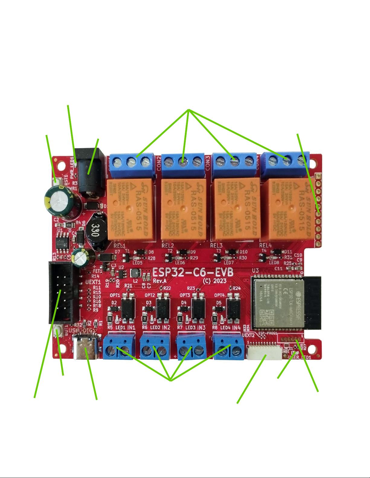
ESP32-C6-EVB layout
7
Reset button
RST1
Power jack input
(8-50)V DC
4 x Opto-coupler inputs with connectors
and status LEDs (30V DC max)
EXT1 header
4 x Relays with connectors and status
LEDs (10A/240VAC max)
User LED
Power-good LED
USB type C
for power and
programming
Boot/User
button BUT1
UEXT1
connector
0.1” step
ESP-PROG1
header
UEXT2 connector
(JST)
Page 8

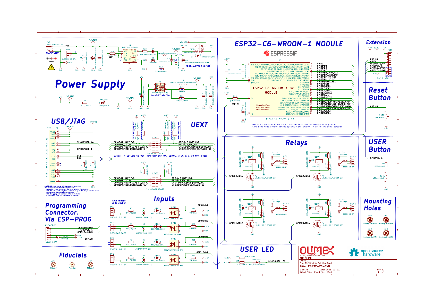
ESP32-C6-EVB schematic
The latest ESP32-C6-EVB schematic is available on the next page.
You can also download PDF export from GitHu b here
All design sources are available also at GitHub here
8
Page 9
Page 10

ESP32-C6-EVB power supply and consumption:
ESP32-C6-EVB can be powered by 3 sources:
• USB-C connector;
• Power jack connector;
• EXT1.pin1 (+5V) note that this wire is connected to the 5V of the USB so when you power ESP32-
C6-EVB from EXT1.pin1 – you should not have USB cable attached at the same time!!!
The typical power consumption is under 1W. Current consumption of ESP32-C6-EVB is approximately
0.06A when powered by 12V DC (applied to the power jack).
10
Page 11
EXT1 connector (GPIO)
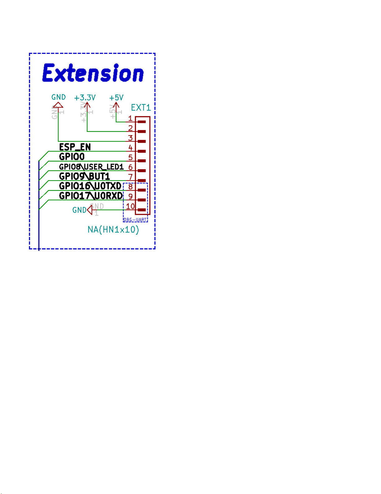
EXT1 pin #1 is +5V pin; it is usually used as output you can also power the board from this pins BUT
ONLY IF the USB-C is not connected! It must be regulated 5V power supply, applying more than 5V will
damage the board;
EXT1 pin #2 is +3.3V DC output, it is not recommended to be used as input since you can’t fully power the
board with 3.3V DC (relays require 5V DC);
EXT1 pin #3, EXT1 pin #10 are GND pins, the board has common ground;
EXT1 pin #4 is ESP_EN also known as reset;
EXT1 pin #5 is GPIO0, which a free pin;
EXT1 pin #6 is GPIO8\USER_LED1 – wired to GPIO8, notice that the user LED is on the same wire
EXT1 pin #7 is GPIO9\BUT1 – wired to GPIO9, notice that the button is on the same wire
EXT1 pin #8 and EXT1 pin #9 are GPIO16\U0TXD and GPIO16\U0RXD they can be used for attaching
external USB-serial converter (like ESP-PROG, USB-SERIAL-CABLE-M, or BB-CH340T) to debug the
board; same pins are also routed to the ESP-PROG1 header.
All GPIOs operate at +3.3V levels. This means you should not connect signals with voltage higher than
3.3V to these ports as this will damage the board.
11
Page 12
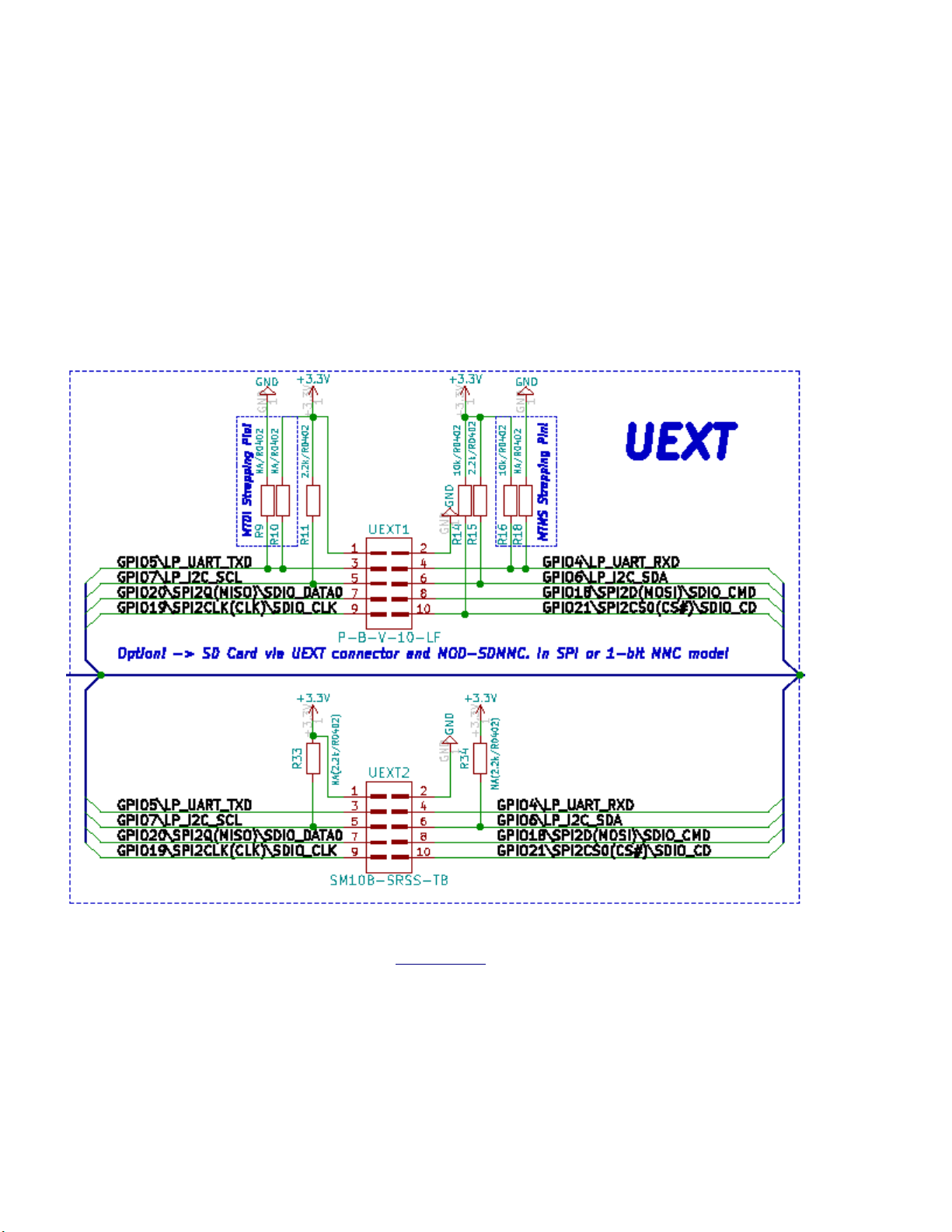
UEXT connectors
UEXT connector stands for Universal EXTension connector and contains +3.3V output and GND power
wires, and I2C, SPI, UART data signals. All signals are at 3.3V levels.
ESP32-C6-EVB has two UEXT connectors – UEXT1 and UEXT2, they have the same signals just different
connector.
UEXT1 uses 0.1” 2.54mm step 2-row boxed plastic connector.
UEXT2 uses the smallest pUEXT which is 1.0mm single row JST connector.
Excerpts for UEXT1 and UEXT2 connectors can be seen below:
Olimex has developed number of extension MODULES compatible with connector UEXT1. There are
temperature, humidity, pressure, magnetic field, light sensors. Modules with LCDs, extra GPIOs, LED
matrices, relays, Bluetooth, GSM, GPS, RFID, RTC, EKG, etc.
If you decide to use UEXT2 you might need adapter for the connector pUEXT. Expect adapter boards and
wires for the JST UEXT2 connector.
12
Page 13

Relays
The board has 4 electro-mechanical relays for analog output, each relay has own status LED. Relay
connectors have Normal open, Normal closed, and Common contacts.
Relay REL1 is connected to GPIO10
Relay REL2 to GPIO11
Relay REL3 goes to GPIO22
Relay REL4 to GPIO23
Inputs
The board has 4 optocouplers for analog input and each input has own status LED. The inputs have + and –
printed under the connector – make sure to first check the polarity or you might damage the board.
Opto OPT1 is connected to GPIO1
Opto OPT2 goes to GPIO2
Opto OPT3 is routed to GPIO3
Opto OPT4 is connected to GPIO15
User LED and button BUT1
The board has user LED and a button that can be used as boot button but also can be used as user button after
initial boot sequence.
LED is connected to GPIO8
Button BUT1 is connected to GPIO9
13
Page 14
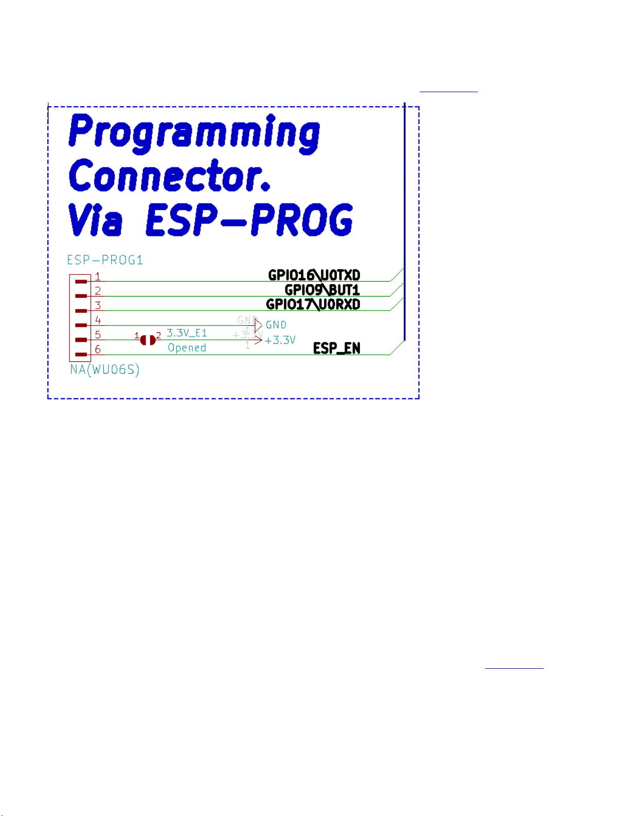
ESP32-PROG header
Used to program the board with external serial-USB programmer like (like ESP-PROG)
Jumper 3.3V_E1
ESP32-C6-EVB has a single SMT jumpers on-board. SMT jumpers are pads that can be separated (open) or
soldered together (closed) to alter the hardware connections of the board and alter the behavior. The SMT
jumpers require basic soldering tools and experience, to separate them you need to cut between the pads and
to close them you need to solder the pads together. SMT jumpers can also be used for measuring and testing
purposes.
Typically you don’t need to change the positions of the jumpers to use the board. It is not recommended to
alter the SMT jumpers unless you know exactly how they alter the board.
3.3V_E1 – enable 3.3V input on pin #5 of ESP-PROG1 connector – risky to leave 3.3V on the ESP-PROG1
connector, this might lead to short-circuit, if the board is already powered and you attach ESP-PROG.
Default state: Open (no 3.3V on pin #5 of ESP-PROG1 connector).
14
Page 15

SOFTWARE
First time start up or how to program the board
The first time setup is pretty straight-forward and the general approach is the following:
1) Install compatible software on your computer (your computer should meet the requirements of the
software); the official and recommended software is ESP-IDF; but you can also use ESP32 package for
Arduino IDE
2) Attach the ESP32-C6-EVB to the computer via USB cable, the cable needs to have USB type C connector
at one end and usually USB type A at the other to fit your computer; a lot of devices use similar cables so you
might already have such cable at home;
3) Force the board in upload/bootloader mode manually:
- Press and hold button BUT1
- Press and release button RST1
- Release button BUT1;
4) Download code. If you are unhappy with the default demos. Maybe check our ESP-IDF demo software for
the relays, user LED, button – Olimex ESP32-C6-EVB demo code and there is some extra info about it here
in this text file;
5) After download is complete you might need to reboot the board to have the user code execute. Future
downloads would require entering upload/bootloader mode again (refer to 3).
Olimex tested firmware and examples
These can be found in the repository here:
https://github.com/OLIMEX/ESP32-C6-EVB
15
Page 16

DOCUMENT REVISION
Revision 2.0 June 2024
- minor improvements
- added links to ESP32 package for Arduino
Revision 1.0 August 2023
- initial release
16
 Loading...