

Page 1
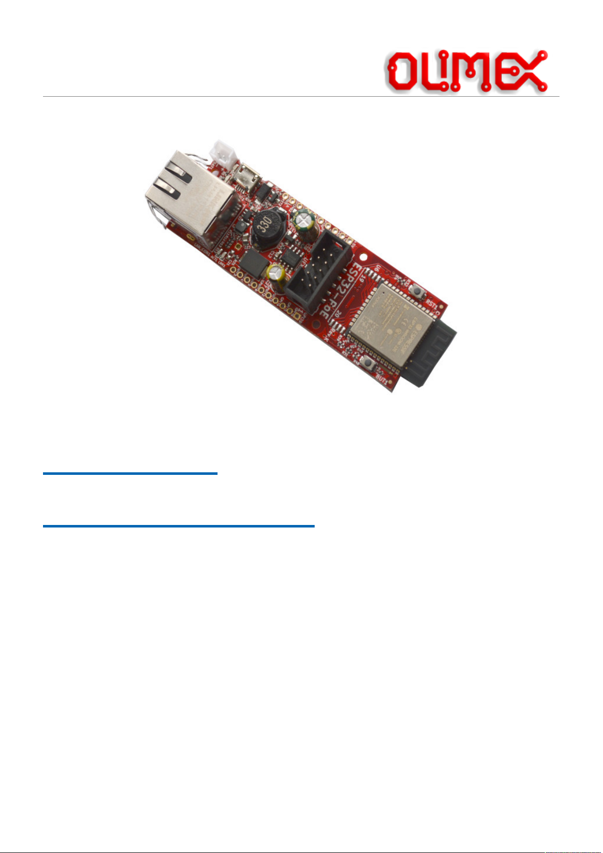
ES32-POE
ESP32-POE-ISO
User Manual
Document revision 2.2.
June 2024
www.olimex.com
1
Page 2

Table of Contents
1. Introduction to ESP32-POE and ESP32-POE-ISO....................................................................................3
1.1. ESP32-POE features..........................................................................................................................4
1.2. ESP32-POE-ISO features...................................................................................................................5
1.3. PoE standard.......................................................................................................................................6
1.4. The difference between ESP32-POE and ESP32-POE-ISO:.............................................................6
1.5. The differences between different variants of ESP32-POE and ESP32-POE-ISO:...........................6
1.6. Order codes for ESP32-POE and accessories:...................................................................................8
1.7. Order codes for ESP32-POE-ISO and accessories:...........................................................................8
2. HARDWARE.............................................................................................................................................9
2.1. ESP32-POE layout:............................................................................................................................9
2.2. ESP32-POE GPIOs:.........................................................................................................................10
2.3. ESP32-POE-ISO GPIOs:.................................................................................................................12
2.4. ESP32-POE(-ISO) schematics.........................................................................................................14
2.5. ESP32-POE(-ISO) power supply.....................................................................................................15
2.5.1. External power sense feature....................................................................................................16
2.5.2. Battery measurement feature....................................................................................................16
2.6. UEXT connector:.............................................................................................................................17
2.7. LED description...............................................................................................................................18
3. SOFTWARE:...........................................................................................................................................19
3.1. Olimex-made software.....................................................................................................................19
4. Frequently asked questions:.....................................................................................................................20
5. Useful links..............................................................................................................................................22
2
Page 3

1. Introduction to ESP32-POE and ESP32-POE-ISO
ESP32-PoE and ESP32-PoE-ISO are ESP32-powered Wi-Fi/Bluetooth/Ethernet development boards with
Power-Over-Ethernet feature. The boards are the perfect addition to any project that requires extra
connectivity.
The PoE is currently handled by TPS2375/6 chip (Si3402-B in older revisions) that is IEEE 802.3afcompliant, including pre-standard (legacy) PoE support.
The PoE powering requires at least 37V DC to operate successfully. The board can takes power from the
Ethernet cable and can be expanded with sensors and more. Perfect solution for Internet-of-Things
projects.
Both ESP32-POE and ESP32-POE-ISO are mature, popular, and well-known products, with wide
software support.
+ Important notice: ESP32-PoE has no galvano isolation of Ethernet's power supply, when you
program the board via the micro USB connector the Ethernet cable should be disconnected (if you have
power over the Ethernet enabled)! Consider using Olimex USB-ISO to protect your computer and board
from accidental short circuits. Also consider using Olimex ESP32-PoE-ISO board instead since it is
insulated.
3
Page 4

1.1. ESP32-POE features
• ESP32-WROOM-32E module WiFi + Bluetooth ® + Bluetooth LE module from Espressif Inc
(ESP32-WROOM-32UE or ESP32-WROVER-E/IE depending on variant)
• ESP32-WROOM-32E/UE have 4MB flash and 520 KB SRAM
• ESP32-WROVER-E/IE have 4MB Flash 520KB SRAM and 8MB PSRAM
• High reliable industrial grade (-40+85C) variant available (-IND)
• CE-RED and LVD certification
• Original design by OLIMEX Ltd
• Power Over Ethernet negotiation circuit, 802.3-compliant, with minimum operating voltage of
37VDC
• DC-DC converter with 3A at 5V output
• Li-Po battery charger and connector
• Battery level monitor pin on ADC
• External power supply detection pin on ADC
• UEXT connector
• User button
• Reset button
• Micro USB with programmer for ESP32 programming
• MicroSD card
• Two extension connectors 0.1" step spaced at 1"
• PCB dimensions: (80 x 28)mm ~ (3.15 x 1.1)"
4
Page 5

1.2. ESP32-POE-ISO features
• ESP32-WROOM-32E WiFi + Bluetooth ® + Bluetooth LE module by Espressif Inc (ESP32WROOM-32UE or ESP32-WROVER-E/IE depending on variant)
• ESP32-WROOM-32E and ESP32-WROOM-32UE have 4MB flash and 520 KB SRAM
• ESP32-WROVER-E/IE have 4MB Flash 520KB SRAM and 8MB PSRAM
• Power Over Ethernet negotiation circuit 802.3 compliant, with minimum operating voltage of
35VDC
• High reliable industrial grade -40+85C available (-IND)
• CE-RED and LVD certification
• Original design by OLIMEX Ltd
• Low power design – 200uA consumption in deep sleep
• Ethernet 100Mb interface with IEEE 802.3 PoE support
• 3000VDC galvanic insulation between the PoE Ethernet part and board's power supply circuit
Micro USB connector for ESP32 programming
• MicroSD card working in 1 bit mode
• LiPo battery charger with LiPo battery connector
• Battery level monitor pin on ADC
• External power supply detection pin on ADC
• DC-DC 2W 5V/400mA
• UEXT connector
• User button
• Reset button
• Two extension connectors, 0.1" step spaced at 1"
• PCB dimensions: (98x28)mm ~ (3.8x1)"
5
Page 6

1.3. PoE standard
ESP32-POE and ESP32-POE-ISO are compliant with the IEEE 802.3af PoE standard and provide up to
15.4 W of DC power (minimum 37V DC and 350 mA). Only 12.95 W are assured to be available at the
powered device as some power dissipates in the cable.
ESP32-POE-ISO has 2W DC-DC 5V-5V insulation converter which prevents electrical influence between
different sources of power but limits the power usage to 2W only!
1.4. The difference between ESP32-POE and ESP32-POE-ISO:
ESP32-POE is not galvanically isolated which means that it’s not safe to connect it to other devices
which use non isolated power supply while it is powered. It should have only one power supply and one
ground attached to it at a time.
+ This means YOU SHOULD NOT CONNECT ESP32-POE to computer’s USB port while it is
powered by Ethernet POE!!! If you connect USB while ESP32-POE is powered by Ethernet you will
damage the board or your computer or both. This will also void the warranty!
ESP32-POE-ISO, on the other hand comes with 3000VDC galvanic insulation between the Ethernet
POE part and ESP32 power supply, so there is no problem to connect to USB and program or debug
while the board is also powered from a PoE source.
1.5. The differences between different variants of ESP32-POE and ESP32-POE-ISO:
ESP32-POE and ESP32-POE-ISO are the base versions with ESP32-WROOM module with 4MB flash
memory and nothing extra.
ESP32-POE-EA and ESP32-POE-ISO-EA have ESP32-WROOM-32UE module with U.FL connector
and external antenna attached.
ESP32-POE-IND and ESP32-POE-EA-IND and ESP32-POE-ISO-IND and ESP32-POE-ISO-EA-IND
use industrial grade components suitable for -40+85C operating temperature.
ESP32-POE-WROVER and ESP32-POE-ISO-WROVER comes with ESP32-WROVER-E chip with
4MB flash and 8MB PSRAM, while ESP32-POE-WROVER-EA and ESP32-POE-ISO-WROVER-EA
have a WROVER module with extra U.FL connector and external antenna attached.
ESP32-POE-16MB, ESP32-POE-EA-16MB, ESP32-POE-ISO-16MB and ESP32-POE-ISO-EA-16MB
feature ESP32-WROOM with 16MB flash memory (as opposed to 4MB).
6
Page 7

Features table:
Name/Features ESP32 module
Flash
size,
MB
External
antenna
Industrial
range
PSRAM,MBIsolated
POE
ESP32-POE ESP32-WROOM-32E-N4 4 - - - -
ESP32-POE-16MB ESP32-WROOM-32E-N16 16 - - - -
ESP32-POE-EA ESP32-WROOM-32UE 4 Y - - -
ESP32-POE-EA-16MB ESP32-WROOM-32E-N16 16 Y - - -
ESP32-POE-EA-IND ESP32-WROOM-32UE 4 Y Y - -
ESP32-POE-IND ESP32-WROOM-32E-N4 4 - Y - -
ESP32-POE-WROVER ESP32-WROVER-E 4 - - 8 -
ESP32-POE-WROVER-EA ESP32-WROVER-IE 4 Y - 8 -
ESP32-POE-ISO ESP32-WROOM-32E-N4 4 - - - Y
ESP32-POE-ISO-16MB ESP32-WROOM-32E-N16 16 - - - Y
ESP32-POE-ISO-16MB-IND ESP32-WROOM-32E-N16 16 - Y - Y
ESP32-POE-ISO-EA ESP32-WROOM-32UE 4 Y - - Y
ESP32-POE-ISO-EA-16MB ESP32-WROOM-32UE-N16 16 Y - - Y
ESP32-POE-ISO-EA-IND ESP32-WROOM-32UE 4 Y Y - Y
ESP32-POE-ISO-IND ESP32-WROOM-32E-N4 4 - Y - Y
ESP32-POE-ISO-WROVER ESP32-WROVER-E 4 - - 8 Y
ESP32-POE-ISO-WROVER-EA ESP32-WROVER-IE 4 Y - 8 Y
+ WROVER module uses two extra ESP32 pins for the PSRAM and these pins can’t be used for other
purposes. This is important especially if you switch from regular version to WROVER version. This is
easily noticeable in the middle of the schematic. GPIO16 and GPIO17 are used by the PSRAM, so
GPIO17 that was used for Ethernet clock was replaced by GPIO0 and GPIO16 was replaced by GPIO33.
You should do the requires software changes in your code if you switch from ESP32-POE to WROVER
version.
7
Page 8

1.6. Order codes for ESP32-POE and accessories:
ESP32-POE commercial grade 0-70C board with internal antenna
ESP32-POE-16MB commercial grade 0-70C board with internal antenna and 16MB flash
ESP32-POE-EA commercial grade 0-70C board with external antenna
ESP32-POE-EA-16MB commercial grade 0-70C board with external antenna and 16MB flash
ESP32-POE-IND industrial grade -40+85C board with internal antenna
ESP32-POE-EA-IND industrial grade -40+85C board with external antenna
ESP32-POE-WROVER commercial grade 0-70C board with 8MB PSRAM and internal antenna
ESP32-POE-WROVER-EA commercial grade 0-70C board with 8MB PSRAM and external antenna
BATTERY-LIPO1400mAh Lipo battery 3.7V 1400mAh – note these batteries can be shipped only
by ground so we can deliver only to EU destinations.
UEXT modules Different sensors, relays, LCDs, RTC, GSM, GPS, accessories which
can be connected to UEXT connector
1.7. Order codes for ESP32-POE-ISO and accessories:
ESP32-POE- ISO commercial grade 0-70C board with internal antenna
ESP32-POE-ISO-16MB commercial grade 0-70C board with internal antenna and 16MB flash
ESP32-POE-ISO-16MB-IND industrial grade -40+85C board with internal antenna and 16MB flash
ESP32-POE-ISO-EA commercial grade 0-70C board with external antenna
ESP32-POE-ISO-EA-16MB commercial grade 0-70C board with external antenna and 16MB flash
ESP32-POE- ISO -IND industrial grade -40+85C board with internal antenna
ESP32-POE- ISO- EA-IND industrial grade -40+85C board with external antenna
ESP32-POE- ISO- WROVER commercial grade 0-70C board with 8MB PSRAM, internal antenna
ESP32-POE- ISO- WROVER-EA commercial grade 0-70C board with 8MB PSRAM, external antenna
BATTERY-LIPO1400mAh Lipo battery 3.7V 1400mAh – note these batteries can be shipped only
by ground so we can deliver only to EU destinations.
UEXT modules different sensors, relays, LCDs, RTC, GSM, GPS, accessories which
can be connected to UEXT connector
8
Page 9
2. HARDWARE
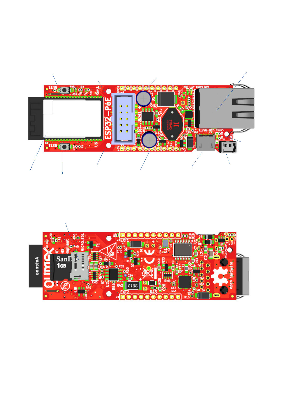
2.1. ESP32-POE layout:
9
User button
mout hole
ESP32
module
reset button
mout hole
GPIOs
GPIOs
USB connector
Ethernet connector
LiPo battery
connector
mout hole
Micro SD card connector
Page 10
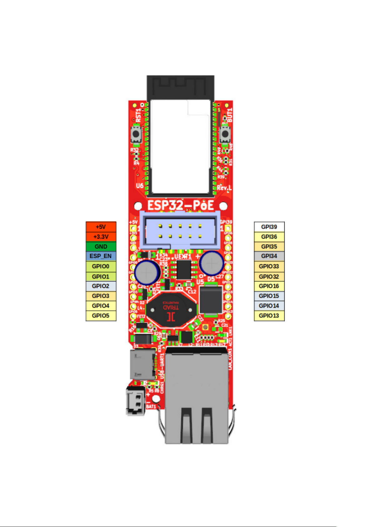
2.2. ESP32-POE GPIOs:
10
Page 11

POWER SUPPLY pads:
+5V 1. Can be input and output; if you use it as input make sure no other 5V sourcesa re applied to the
board (having Li-Po battery is OK);
2. When the board is attached to USB or to Ethernet PoE this line can be used ONLY as output
to power attached peripherals;
3. If you want to use as input i.e. to feed power from external 5V to this line make sure that
board is not connected to USB!
4. When you use the 5V line as output to power external devices it can provide up to 0.8A @ 5V
(i.e. 4W) maximum. This includes the 3.3V power output. The combined power draw of +5V
output and +3.3V output must not exceed 4W!
+3.3V output which can source up to 0.5A @ 3.3V i.e. (1.65W) Make sure the combined power
sourced from +3.3V and +5V does not exceed 4W!
GND Ground, the board has common ground.
GPIO pads:
ESP_EN resets the ESP32 module
GPIO0, GPIO2 are boot mode bootstrap pins make sure they are properly configured during power up
GPIO1, GPIO3 are used for USB programming, they can be freed up if you won’t further program the
boar via USB
GPIO2, GPIO14, GPIO15 are used for the SD-card, if no SD card is preset they are free to use
GPIO2, GPIO4, GPIO5, GPIO13, GPIO14, GPIO15, GPIO16, GPIO36 are shared on both UEXT
and EXT headers so if you use them on the one connector do not use them at the other
GPI39 is connected to measure external power supply voltage
GPI34 is connected to user button and has 10K pullup
GPI35 is free to use by default but may be connected to measure the LiPo battery voltage if you close
BAT_SENS_E1 jumper
+ESP32-POE-WROVER and ESP32-POE-WROVER-EA have no GPIO16 or GPIO17 led out, since
they are used for the PSRAM. These are replaced by GPIO33 and GPIO0. GPIO17 being replaced by
GPIO0 is crucial for the Ethernet connectivity, since GPIO17/GPIO0 is Ethernet clock out. Make sure to
use new assignments in your software if your board variant comes with the WROVER chip.
The ESP32 chip has very advanced multiplexing and you can define any free GPIO pin for I2C, UART,
SPI operation as long as you are within the maximum supported (some penalties to SPI's maximum
frequency apply, when not using the dedicated pins). Notice that some ESP32 pins can only be inputs.
Defining pins is for another job is purely software effort.
For further analysis of pins it is highly recommended to check on the schematic.
11
Page 12
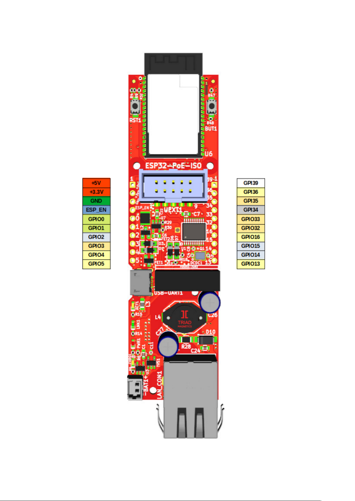
2.3. ESP32-POE-ISO GPIOs:
12
Page 13

POWER SUPPLY pads:
+5V 1. Can be used as either input and output. f you use it as input make sure no other 5V source is
applied to the board (Li-Po battery is OK);
2. When the board is connected to USB or to Ethernet PoE this line can be used as output and
power supplement electronic
3. if you want to use as input i.e. to feed power from external 5V to this line make sure board is
not connected to USB!
4. when you use as output i.e. you feed external electronics from it up to 0.2A @ 5V (i.e. 1W)
can be sourced maximum. This includes the 3.3V power output. The combined power
must not exceed 1W.
+3.3V output which can source up to 0.33A @ 3.3V i.e. (1W) - make sure the combined power
sourced from +3.3V and +5V does not exceed 1W
GPIO pads:
ESP_EN resets ESP32 module
GPIO0, GPIO1 are used only during programming, after that are free to use
GPIO2, GPIO14, GPIO15 are used for the SD-card, if no SD card they are free to use
GPIO2, GPIO4, GPIO5, GPIO13, GPIO14, GPIO15, GPIO16, GPIO36 are shared on both UEXT
and EXT headers so if you use them on the one connector do not use on the other
GPI39 is connected to measure external power supply voltage;
GPI35 is used for battery measurement of the LiPo battery;
GPI34 is connected to used button and has a 10K pullup resistor.
+ESP32-POE-ISO-WROVER and ESP32-POE-ISO-WROVER-EA have no GPIO16 and GPIO17
led out, since they are used for the PSRAM. GPIO16 is replaced by GPIO33. GPIO17 is replaced by
GPIO0, this is important for the Ethernet connectivity, since GPIO17/GPIO0 is Ethernet clock out. Make
sure to use new assignments if your board variant comes with the WROVER chip.
The ESP32 chip has very advanced multiplexing and you can define any free GPIO pin for I2C, UART,
SPI operation as long as you are within the maximum supported (some penalties to SPI's maximum
freqncy apply, when not using the dedicated pins). Notice that some ESP32 pins can only be inputs.
Defining pins is for another job is purely software effort.
For further analysis of pins it is highly recommended to check on the schematic.
13
Page 14

2.4. ESP32-POE(-ISO) schematics
This is an open hardware design made with KiCAD. All design files and exports can be found at our
GitHub.
ESP32-POE schematic hardware revision L is at GitHub
ESP32-POE board revision changes are at GitHub
ESP32-POE-ISO schematic revision L is at GitHub
ESP32-POE-ISO board revision changes are at GitHub
14
Page 15

2.5. ESP32-POE(-ISO) power supply
ESP32-POE(-ISO) can be powered by 4 sources:
• Ethernet PoE
• USB-micro connector
• Li-Po battery
• EXT1 pin 1 (+5V) but note that this signal is connected to USB 5V signal so when you power via
this EXT1 pin you should not connect the board to the USB!
- The standard power consumption of ESP32-POE(-ISO) is between 50mA and 200mA depending on the
operation mode. When using power-down modes and Li-Po battery power it can go down to micro
amperes.
- Li-Po battery gets automatically charged with about 100mA when external power supply is present.
When the LiPo battery is attached and external power supply is missing internal DCDC step-up converter
and switching circuit automatically powers ESP32-POE from the battery. 1400mAh battery will provide
about 8 hours of stand alone operation.
+The LiPo battery connector is JST 2.0 mm connector and with Olimex’s battery polarity. If you use
batteries from other manufacturers please make PLUS and MINUS are connected properly as you may
damage the board!
+ Is it safe to have USB and PoE connected and enabled at the same time? If you are using ESP32-POE
or any of its variants – no, it is not safe and should be avoided at all costs. If you are using ESP32-POEISO or any of its variants – yes, it is safe to have them both attached and enabled.
15
Page 16

2.5.1. External power sense feature
This allows to detect when the board has external powering. This is helpful if you want to switch between
different power modes depending on whether the board is powered from a battery or external power
source. By default the external power sense is enabled and it is available on GPI39!
Refer to this Arduino IDE example to see how you can check for the presence external power and check
the battery measurement:
https://github.com/OLIMEX/ESP32-POE/blob/master/SOFTWARE/ARDUINO/
ESP32_PoE_PowerReading/ESP32_PoE_PowerReading.ino
2.5.2. Battery measurement feature
This allows to measure the Li-Po battery’s voltage. This is helpful so you can evaluate when the battery is
going to drain out so you can power off the board safely or switch to more conservative power method.
In ESP32-POE and its variants the battery measurement features is disabled by default but you can
enabled it by soldering together the pads of STM jumper BAT_SENS_E1 jumper, after closing it – it will
be routed to GPI35!
In ESP32-POE-ISO and its variants – the battery measurement is enabled and it is available on GPI35!
Refer to this Arduino IDE example to see how you can check for external power and check the battery
measurement:
https://github.com/OLIMEX/ESP32-POE/blob/master/SOFTWARE/ARDUINO/
ESP32_PoE_PowerReading/ESP32_PoE_PowerReading.ino
16
Page 17
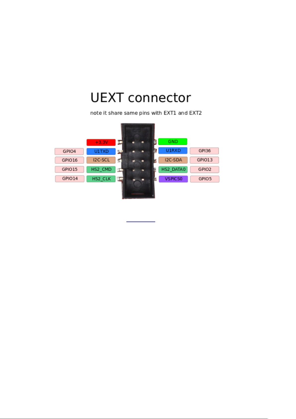
2.6. UEXT connector:
UEXT connector stands for Universal EXTension connector and typically contains +3.3V, GND, UART,
I2C, SPI signals.
UEXT is 0.1” 2.54mm step boxed plastic connector. All signals are with 3.3V levels.
Olimex has developed number of extension MODULES compatible with this connector. There are
temperature, humidity, pressure, magnetic field, light sensors. Modules with LCDs, LED matrix, relays,
Bluetooth, Zigbee, Wi-Fi, GSM, GPS, RFID, RTC, EKG, sensors, and more.
17
Page 18

2.7. LED description
Board comes with 4 on-board status LEDs. These are not connected to the ESP32 directly and can’t be
used as general purpose LEDs.
LED CHRG1 shows whether the Li-Po battery attached to the board is currently charging. When it is off
it means that either there is no battery attached or it is already fully charged. Refer to "BL4054/BL4054B"
datasheet and check for "CHRGb" port for more detailed information.
LED PWR1 is turned on when there is 5V DC applied to the board. It only actives from external power
supply, USB power supply, or PoE powering. It won't turn on when board is powered from a Li-Po
battery at BAT1 connector (to conserve energy required to power that LED).
LEDs LNK1 and ACT1 are Ethernet link and activity LEDs. LNK1 is turned on when 100 Mbps speed is
detected, and turns off at 10Mbps or less. ACT1 blinks when activity is detected. For more information
about their behavior, refer to the manual of "LAN8710A/LAN8710AI" and check the table describing
"REGOFF" port (ACT1 is connected to it) and "nINTSEL" port (LNK1 is connected to it).
During USB power up the CHRG1 and PWR1 LEDs should light up.
Important! In order to reduce current consumption the LEDs would remain off when the board is
powered from Li-Po battery! Do not count on the LEDs when the board is powered only from a LiPo battery!
18
Page 19

3. SOFTWARE:
ESP32-POE and ESP32-POE-ISO are very popular boards and supported by a lot of software tools,
among them (there are ready-to-use configs for ESP32-POE and ESP32-POE-ISO):
• Espressif ESP-IDF
• Arduino IDE
• MicroPython
• ESPhome
• PlatformIO
3.1. Olimex-made software
We provide some examples for basic functions at our GitHub:
- For Arduino you can find them here:
https://github.com/OLIMEX/ESP32-POE/tree/master/SOFTWARE/ARDUINO
- For ESP-IDF here:
https://github.com/OLIMEX/ESP32-POE/tree/master/SOFTWARE/ESP-IDF
19
Page 20

4. Frequently asked questions:
• Is it safe to have USB powering and PoE powering connected and enabled at the same time?
- If you are using ESP32-POE or any of its variants – no, it is not safe and should be avoided at
all costs.
- If you are using ESP32-POE-ISO or any of its variants – yes, it is safe to have them both
enabled.
• Where are I2C, UART, SPI pins exposed?
The ESP32 chip has very advanced multiplexing and you can define any free GPIO pin for I2C,
UART, SPI operation as long as you are within the maximum supported (some penalties to SPI's
maximum frequency apply, when not using the dedicated pins). Notice that some ESP32 pins can
only be inputs. Double check if the pins you want to use are free. Defining pins for another
function is a purely software effort.
• I provide 24V to the Ethernet of ESP32-PoE-ISO's but it doesn't seem powered. What is the
problem?
TPS2375PW (Si3402) would NOT work with 24V DC. The recommended voltage is 48V DC and
the minimum is around 37V DC. For more info refer to TPS2375PW's (Si3402-B's) datasheet.
• I power the board from the Ethernet connector. What current do I have available for
additional circuits?
Depends on the board used. If you are using ESP32-POE the PoE circuit can safely provide up to
4W, i.e. 800mA @ 5V. Part of this wattage is used to power the ESP32 module, the battery
charger, and other circuits part of the board design; the remaining wattage is available for
additional circuits (up to around 600mA). Make sure the total current consumption does not
exceed 800mA @ 5V.
If you are using ESP32-POE-ISO the isolated DCDC that we use provides up to 2W, this means
400mA @ 5V, 100mA are reserved for the battery charge (available if no battery is connected) and
100mA are provided for ESP32, which leaves up to 200mA @ 5V for your additional circuits.
• I power the board from the battery connector. The LEDs remain off. Is it broken?
Probably not. This is a low-power design. The LEDs would not turn on when operating on battery
to save power. You need other ways to determine if it works or not. For example, something over
the serial lines or over the Ethernet (with no PoE enabled else it would get powered from there).
20
Page 21

• A specific resistor gets very hot! What is this component? Is it safe? Can I remove it?
This is probably the resistor that is required by the IEEE standards. It is used for MPS (maintain
power signature). Search online "maintain power signature poe" to get the general idea.
We didn't ensure MPS in the first hardware revisions of the board (e.g. had no resistor in place),
but this caused availability problems when using some power saving modes – the board consumed
less wattage than PoE equipment can detect, which led to PoE equipment shutting the board off.
If you have soldering experience and the resistor bothers you, you might try desoldering it and see
if that effects your setup negatively. Notice that we don't recommend doing so.
• ESP32-PoE and ESP32-POE-ISO don't work well with bauds over 115200. What to do?
Some older drivers might have wrong timings, causing worse throughput. Download and install
the latest drivers for CH340.
• Help! Ethernet is not working. I use ESP32-POE-WROVER and ESP32-POE-ISOWROVER
The WROVER module require two addition pins compared to the WROOM module. This
required two pin changes – GPIO16 and GPIO17 are used by the PSRAM of the WROVER, so
we have replaced GPIO16 with GPIO33 and GPIO17 with GPIO0. The change of GPIO17 affects
the Ethernet since it serves as Ethernet clock source. Make sure to replace GPIO17 with GPIO0 in
your code or configuration!
21
Page 22

5. Useful links
The main pages of ESP32-POE and ESP32-POE-ISO are the main hubs for other locations, make sure to
first check the product page at our web-site.
ESP32-POE main product page:
https://www.olimex.com/Products/IoT/ESP32/ESP32-POE/open-source-hardware
ESP32-POE-ISO main product page:
https://www.olimex.com/Products/IoT/ESP32/ESP32-POE-ISO/open-source-hardware
22
 Loading...