


Chapter 0
General Manual Information
OL400/410ex (96-01-30)

Chapter 1
1.1 General Description
General Information
The OL400e, OL410e, and the OL410e/PS are compact Light Emitting Diode (LED) page
printers. The printers utilize an LED head for the exposure method. Dry electrophotography is
used as the development method. The print resolution is 300 x 300 dots per inch. The OL410e
and the OL410e/PS (in PCL Mode) can print at 300 x 1200 dots per inch. The printers have
a continuous print speed of up to 4 sheets per minute.
All three products include both a Centronics parallel interface and a 9-pin RS232 serial interface
as standard features. The OL410e/PS includes an LocalTalk interface, which can only be used
in PostScript mode. Theprinters have automatic interface switching capabilities, a power-saving
standby mode, free-paper sizing (which allows printing on custom size paper), and graphic
compression capabilities (for full-page business graphics).
The OL400e utilizes 512 Kbyte of standard Random Access Memory (RAM). An optional
expansion memory board can be installed. Up to 4 Mbyte of RAM (in 1 Mbyte increments)
can be installed on the expansion board, providing up to 4.5 Mbyte of total RAM in the OL400e.
The OL410e utilizes 2 Mbyte of standard Random Access Memory (RAM). The main controller
board contains 1 Mbyte of RAM. The standard expanded memory board contains 1 Mbyte.
An optional expansion memory board can be installed in place of the standard expanded memory
board. The optional board contains 2 Mbyte of RAM. However, up to 4 Mbyte of RAM (in 1 Mbyte
increments) can be installed, providing up to 5 Mbyte of total RAM in the OL410e.
The OL410e/PS utilizes 2 Mbyte of standard Random Access Memory (RAM). 1 Mbyte is on the
main control board. 1 Mbyte is on the PostScript Board. The PostScript board will accept and
additional 3 Mbytes of RAM, providing up to 5 Mbyte of total RAM in the OL410e/PS.
A universal / letter cassette is included with each printer. Legal, executive, and A4 trays are
available.
The printers will print on a variety of paper types, labels, and transparencies.
OL400/410ex (96-01-30)

1.2 Product Specifications
1.2 PRODUCT SPECIFICATIONS
1.2.01 Print Specifications
Exposure Method
Stationary LED Head
Development Method
Dry Electrophotography
1.2.02 Print Speed
Continuous Print
4 sheets per minute
Warm-up Time
Approximately 60 seconds with standard memory
Approximately 90 seconds with the memory expansion board installed
1.2.03 Print Resolution
Standard Printing Mode
300 x 300 dots/inch
Enhanced Printing Mode(OL410e and OL410e/PS in HP LaserJet III mode)
300 x 1200 dots/inch (600 dpi Class Printing)
1.2.04 Symbol Sets
40 Symbol Sets
1.2.05 Paper Feed Method
Automatic Feed
Manual Feed
1
.2.06 Paper Delivery Methods
Face down
Face up
1.2.07 Interface Capabilities
OL400e/OL410e Interfaces
Centronics Parallel Interface
RS232 Serial Interface
OL410e/PS Interfaces (with Auto-switching)
RS232 Serial Interface
Centronics Parallel Interface
LocalTalk (PostScript only)
1.2.08 Emulations
OL400e
HP LaserJet IIP
OL410e
HP LaserJet III (HP PCL 5)
OL410e/PS
HP LaserJet III (HP PCL 5)
Adobe PostScript Level 2
NOTE: When operating under the DOS environment, the OL410e/PS supports auto-emulation
switching by means of the Oki-Switch software, which is included with the printer.
1.2.09 Available Fonts
OL400/410ex (96-01-30)

The OL400e and OL410e printers contain four resident bit mapped typefaces which can be printed
in both landscape and portrait orientations.
Courier
Swiss
Line (LN) Printer
Dutch
The OL410e contains three scalable typefaces, in addition to the four bitmapped typefaces.
CG Times
Univers
Courier
The OL410e/PS contains the following fonts.
Resident Fonts
Adobe PostScript
35 (Type 1 Fonts)
2 (Multiple Master Fonts) - for use with Adobe ATM 3.0 and Adobe Acrobat
PCL5
12 Scalable Fonts
Bit mapped Fonts/Typefaces
2 Line Printer Fonts
USPS Barcode Fonts
The OL400e and OL410e use twenty bit mapped fonts from the four typefaces.
Courier 10 cpi
Courier Bold 10 cpi
Courier Italic 10 cpi
Courier 12 cpi
Courier Bold 12 cpi
Courier Italic 12 cpi
LN Printer 16.67 cpi
Swiss Bold Proportional (B)
Swiss Bold Proportional (F)
Dutch Proportional (B)
Dutch Bold Proportional (B)
Dutch Italic Proportional (B)
Dutch Compressed (B)
Dutch Bold Compressed (B)
Dutch Italic Compressed (B)
Dutch Proportional (F)
Dutch Bold Proportional (F)
Dutch Italic Proportional (F)
Dutch Proportional (B)
Dutch Compressed (B)
NOTE: cpi = Characters Per Inch
OL400/410ex (96-01-30)

1.3 Paper Specifications
1.3 PAPER SPECIFICATIONS
CAUTION: All paper (all types) should be designed for xerographic printing.
Envelopes, labels, and transparencies should only be fed from the top paper tray or manually.
Use the face-up paper ejection path. DO NOT use the optional second paper feed mechanism for
these items.
1.3.01 Paper Types
Letter
Size: 8.5" x 11" (216 mm x 279 mm)
Feed: Automatic or Manual
Weight
Minimum: 16 lbs. (60 g / m2)
Maximum: 24 lbs. (90 g / m2)
Recommended: 20 lbs. (75 g / m2)
Legal
Size:8.5" x 13" (216 mm x 330 mm) 8.5" x 14" (216 mm x 356 mm)
Feed: Automatic (with optional paper tray)
Executive
A4
A5
Weight
Minimum: 16 lbs. (60 g / m2)
Maximum: 24 lbs. (90 g / m2)
Recommended: 20 lbs. (75 g / m2)
Size: 7.25" x 10.5" (184 mm x 267 mm)
Feed: Automatic (with optional paper tray) or Manual
Weight
Minimum: 16 lbs. (60 g / m2)
Maximum: 24 lbs. (90 g / m2)
Recommended: 20 lbs. (75 g / m2)
Size: 8.27" x 11.69" (210 mm x 297 mm)
Feed: Automatic (with optional paper tray)
Weight
Minimum: 16 lbs. (60 g / m2)
Maximum: 24 lbs. (90 g / m2)
Recommended: 20 lbs. (75 g / m2)
Size: 5.83 " x 8.27" (148 mm x 210 mm)
Feed: Automatic (with optional paper tray)
Weight
Minimum: 16 lbs. (60 g / m2)
Maximum: 24 lbs. (90 g / m2)
OL400/410ex (96-01-30)

A6
B6
Envelope
Recommended: 20 lbs. (75 g / m2)
Size: 4.13" x 5.83" (105 mm x 148 mm)
Feed: Automatic (with optional paper tray)
Weight
Minimum: 16 lbs. (60 g / m2)
Maximum: 24 lbs. (90 g / m2)
Recommended: 20 lbs. (75 g / m2)
Size: 7.17" x 10.12" (182 mm x 257 mm)
Feed: Automatic (with optional paper tray)
Weight
Minimum: 16 lbs. (60 g / m2)
Maximum: 24 lbs. (90 g / m2)
Recommended: 20 lbs. (75 g / m2)
Size
Minimum: 3.5" x 7.5" (89 mm x 191 mm)
Maximum: 7.2" x 10.1" (183 mm x 257 mm)
Feed: Automatic (with optional paper tray) or Manual
Weight
Minimum: 16 lbs. (60 g / m2)
Maximum: 24 lbs. (90 g / m2)
Recommended: 20 lbs. (75 g / m2)
Labels
Manual feed / Face up delivery only
Use labels designed specifically for xerographic printing
Transparencies
Manual feed / Face up delivery only
Must be able to withstand the heat of the fusing process
1.3.02 Free Paper Size
The Free Paper Size menu feature allows the end user to print on custom size paper without
a paper size error.
Normally, if the paper is loaded in the paper tray is NOT the same size selected in the software,
a PAPER SIZE error will be displayed when a print job is sent. Enabling the Free Paper Size menu
feature will override this operation.
Free Paper Size Dimensions
Width
Size: 3.4" x 8.5" (86.4 mm x 216 mm)
Length
Size: 5.5" x 14" (140 mm x 355.6 mm)
Feed
Automatic (with optional paper tray)
OL400/410ex (96-01-30)

Manual
Weight
Minimum: 16 lbs. (60 g / m2)
Maximum: 24 lbs. (90 g / m2)
Recommended: 20 lbs. (75 g / m2)
To enable Free Paper Size, follow this procedure.
- Place the printer OFF-LINE.
- Press LAST / Paper Size for two seconds.
- Press NEXT + repeatedly until FREE is displayed on the operator panel.
- Press ENTER to select FREE as the default setting.
- Press ON-LINE to exit the menu.
- Place the custom size paper stock in Tray 1, the Manual Feed Tray, Tray 2,
or the Multi-Purpose Feeder.
- Run the print job.
OL400/410ex (96-01-30)

1.4 Physical Specifications
1.4 PHYSICAL SPECIFICATIONS
1.4.01 Outside Dimensions
Width: 12.6 inches (320 mm)
Height: 6.3 inches (160 mm)
Depth: 14.17 inches (360 mm)
1.4.02 Printer Weight
24 lbs. (11 kg)
1.4.03 LED Array
1.4.03 LED Array
Number of LED Elements: 2560
OL400/410ex (96-01-30)

1.5 Power Requirements
1.5 POWER REQUIREMENTS
1.5.01 Input Power
120 VAC + 5.5% - 15%
220/240 VAC +/- 10%
1.5.02 Power Consumption
Peak
Approximately 600 Watts
Operation (typical)
Approximately 80 Watts
Idle
Approximately 40 Watts
Power Save
Approximately 15 Watts
OL400/410ex (96-01-30)

1.6 Environmental Conditions
1.6 ENVIRONMENTAL CONDITIONS
1.6.01 Ambient Temperature
Operation
50 to 90 degrees Fahrenheit
10 to 32 degrees Celsius
Storage
14 to 110 degrees Fahrenheit
-10 to 43 degrees Celsius
1.6.02 Printer Noise Level
Operation
50 dBA (A) or less
Standby
45 dBA (A) or less
OL400/410ex (96-01-30)

1.8 Options
1.8 OPTIONS
1.8.01 Memory Expansion
OL400e
Expansion RAM Board: contains 1 Mbyte. Can be expanded up to 4.5 Mbyte
in 1 Mbyte increments
OL410e
Expansion RAM Board: Contains 2 Mbyte. Can be expanded up to 5 Mbyte
in 1 Mbyte increments
OL410e/PS
Resident RAM - 2 MByte
Optional RAM - 3 MByte (in 1 Mbyte increments)
Maximum RAM - 5 Mbyte
1.8.02 Font Cards
Bit mapped (OL400e and OL410e)
OKIPRO 65
Bar Codes Plus
MICRO DOCS
Tax
Scalable (OL410e and OL410e/PS in PCL5 emulation)
Distinctive Documents
Perfect Presentations
Wordperfect II Scalable
1.8.03 Paper Trays
100 Sheet Letter Tray
100 Sheet Legal Tray
OL400/410ex (96-01-30)

1.9 Consumables
1.9 Consumables
1.9.01 Image Drum Cartridge Kit
Contents
Image Drum Cartridge
1.9.02 Toner Cartridge Kit
Contents
Toner Cartridge
LED Lens Cleaner
Toxicity
No carcinogens are contained.
OL400/410ex (96-01-30)

1.10 Memory Specifications
1.10 Memory Specifications
1.10.01 ROM
Main Controller Program ROM
OL400e
512 Kbyte
OL410e
1 Mbyte
1.10.02 RAM
OL400e
Standard: 512 Kbyte
Expansion: Up to 4.5 Mbyte (in 1 Mbyte increments)
OL410e
Standard: 2 Mbyte (1 Mbyte on the main controller
and 1 Mbyte on the expanded memory board)
Expansion (on the expansion memory board, which replaces the
1 Mbyte expanded memory board)
Up to 5 Mbyte (in 1 Mbyte increments)
OL410e/PS
Standard - 2 MByte (1 Mbyte on the main controller and 1 Mbyte
on the PostScript board)
Expansion - 3 MByte (in 1 Mbyte increments) on the PostScript board
Maximum RAM - 5 Mbyte
1.10.03 EEPROM
NOTE: EEPROM = Electrically Erasable Programmable Read Only Memory
Main Controller EEPROM
1024 x 1 bit serial input/output
OL400/410ex (96-01-30)

1.11 Reliability Specifications
1.11 Reliability Specifications
1.11.01 Mean Pages Between Failure (MPBF)
Approximately 24,000 pages
1.11.02 Mean Time To Repair (MTTR)
Approximately 20 minutes
1.11.03 Estimated Toner Cartridge Life
Approximately 2,000 pages at 5% density
1.11.04 Image Drum Life
Approximately 20,000 pages: Continuous print at 5% density
Approximately 18,000 pages: at 7 pages per print job
1.11.05 Printer Duty Cycle
Approximately 6,000 pages per month
OL400/410ex (96-01-30)

2.1 Printer Overview
2.1 PRINTER OVERVIEW
2.1.01 General Information
This section describes the operation of the product in the order listed below.
Control Process
Mechanical Operation
Printing Process
Sensors and Switches
OL400/410ex (96-01-30)
2.2 Control Process
2.2 CONTROL PROCESS
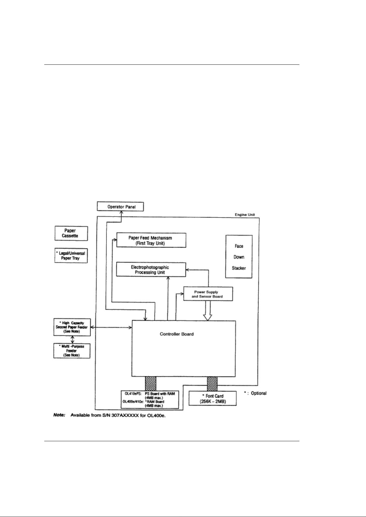
2.2.01 General Information
The control process involves regulating the reception of data from the host system interface,
receiving data and commands from the host system, and generating bit-image data. The control
process also includes sending data and commands to the print engine where the print process is
performed.
The control process is performed by the following hardware components.
Main Controller Board
Expanded RAM Board (OL410e ONLY)
Expansion RAM Board Option
Font Card Option
Configuration Diagram
OL400/410ex (96-01-30)
2.2.02 Block Diagrams 400E
2.2.02 Block Diagrams
OL400e
OL400/410ex (96-01-30)
OL400/410ex (96-01-30)
2.2.02 Block Diagrams 410E
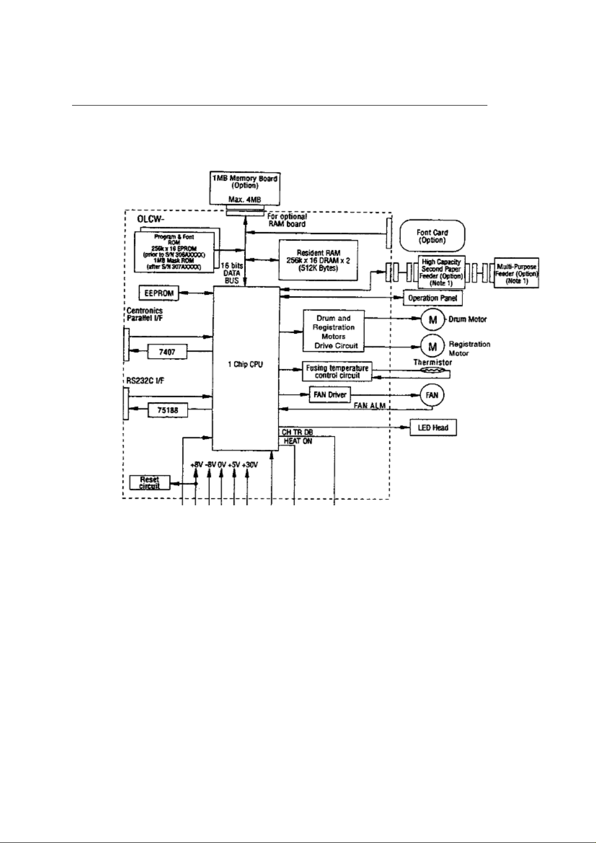
2.2.02 Block Diagrams
OL410e
OL400/410ex (96-01-30)
OL400/410ex (96-01-30)
2.2.02 Block Diagrams 410E/PS
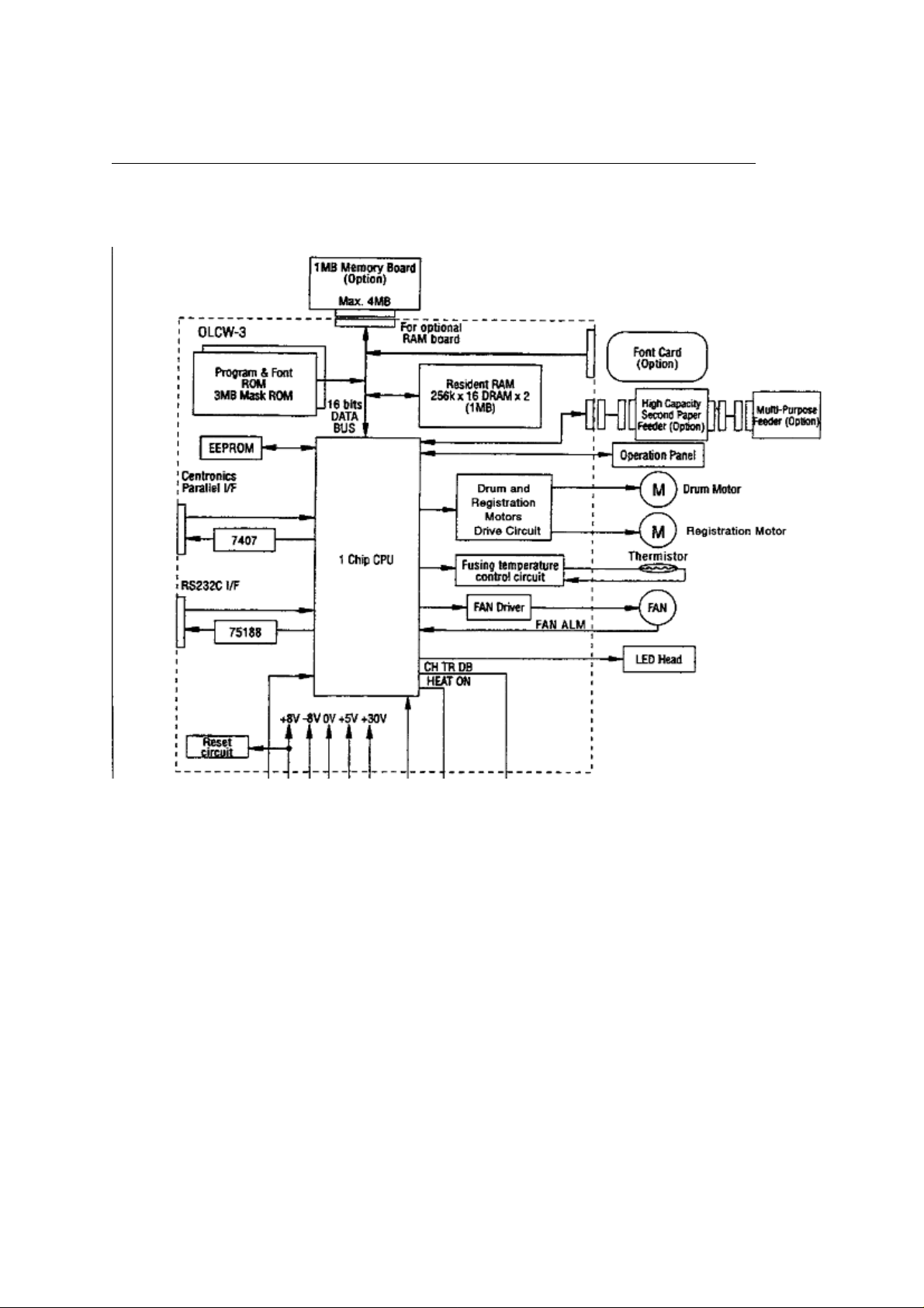
2.2.02 Block Diagrams
OL410eps
OL400/410ex (96-01-30)
OL400/410ex (96-01-30)

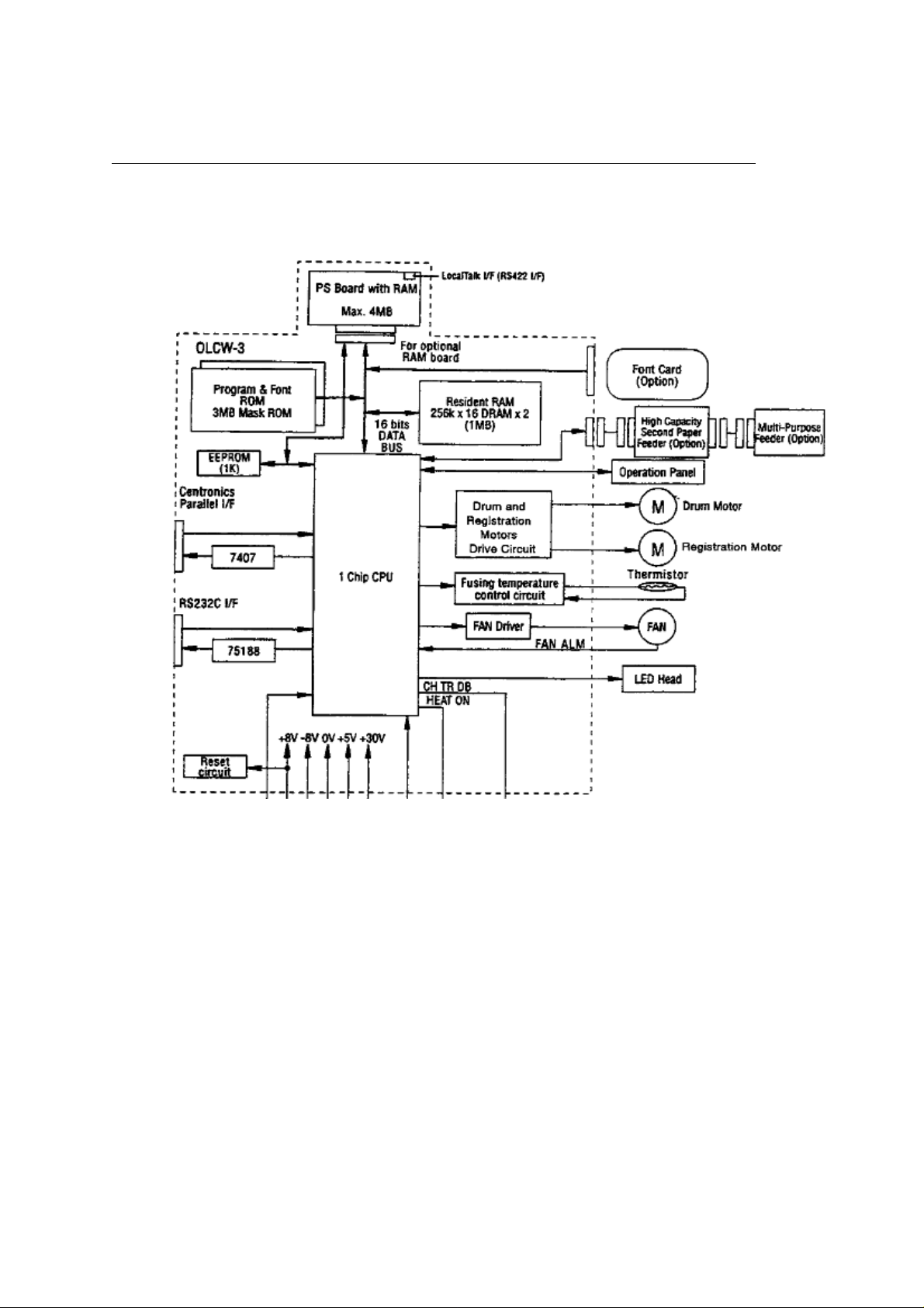
2.2.03 Main Controller Board (OLCW) Overview
2.2.03 Main Controller Board
Overview
The principal components of the main controller board are listed below.
- 16 Mhz Oscillator
- ASIC (with a built-in RISC microprocessor)
- PROM (contains printer control program)
- ROM (contains the bit-mapped fonts)
- EEPROM
- Dynamic RAM (DRAM)
OL400e
512 Kbyte
OL410e
1 Mbyte with an additional 1 Mbyte contained on the Expanded RAM Board
OL410e
1 Mbyte with an additional 1 Mbyte contained on the PostScript Board
Driver Circuitry
RS232 Serial Interface Port
Centronics Parallel Interface Port
Both the print engine functions and the control functions are integrated on the main controller
board. Most of the logic needed to perform print engine functions and control functions is
integrated internally in the microprocessor.
OL400/410ex (96-01-30)

Main Controller Board Functions
Main Controller Board Functions
General Information
The functions of the main controller board are listed below.
- Reception Control..................................... (
- Command Analysis Processing................... (
- Font Processing....................................... (
- Buffer Read Operation.............................. (
- Engine Control......................................... (
- Operation Panel Control...................... (
- Operation Panel Functions.................. (
- Sensor Control......................................... (
- Print Operation........................................ (
- Electrophotographic Processing Action........ (
- LED Array Operation................................. (
- Fuser Lamp Operation.............................. (
- Registration Motor Operation..................... (
- Drum Motor Operation.............................. (
- DC Fan Operation
)
)
)
)
)
)
)
)
)
)
)
)
)
)
OL400/410ex (96-01-30)

Reception Control
Main Controller Board Reception Control
As data is received from the host system, the CPU sets the BUSY-P signal to ON and reads
the parallel data lines (DATA 1 - DATA 8). The I-PRIME signal (Enable/Disable) of the parallel
interface port can be specified through the menu.
The serial data from the host system is received by the built-in serial controller of the
microprocessor.
Both the parallel and serial interface ports can receive data. The port that receives data first
will be activated.
OL400/410ex (96-01-30)

Command Analysis Processing
Main Controller Board Command Analysis Processing
- The OL400e emulates the HP LaserJet Series IIP.
- The OL410e emulates the HP LaserJet Series III.
- The OL410e/PS emulates the HP LaserJet Series III
and also contains a PostScript (Level 2) Interpreter
OL400/410ex (96-01-30)

Font Processing
Main Controller Board Font Processing
OL400e
- Bit mapped fonts are available for the HP LaserJet Series IIP emulation.
OL410e
- Bit mapped and scalable fonts are available for the HP LaserJet Series III emulation.
OL410e/PS
- Scalable fonts are available for the HP LaserJet Series III emulation.
- PostScript Fonts are contained on the PostScript Board.
OL400/410ex (96-01-30)

Main Controller Board Buffer Read Operation
Main Controller Board Buffer Read Operation
Bit images written in the raster buffer (registers) are converted to serial data. The contents
of the registers are transferred to the engine control section of the microprocessor (MPU)
on the main controller board.
OL400/410ex (96-01-30)

Engine Control Functions
Main Controller Board Engine Control Functions
Engine control functions are executed when the CPU receives a print request signal.
OL400/410ex (96-01-30)

Operation Panel Control
Main Controller Board Operation Panel Control
General Information
The operation panel consists of the following circuits.
- MPU Interface Integrated Circuit
- LCD Control Driver
- LCD Display
- LED
- Operation Panel Sheet
- Contact Switches (There are eight contact switches).
OL400/410ex (96-01-30)

Operation Panel Functions
Main Controller Board Operation Panel Functions
The operation panel LCD displays the printer's operational status and error messages. The
operation panel is also used to modify the printer menu.
The operation panel is connected to the main controller board through connector CN1 of
the contact switch board and CN5 of the main controller board.
The LCD control driver board is connected to the contact switch board. The connector on
the contact switch board is CN2, and the connector on the control drive board is CN3.
The operation panel is controlled by the CPU of the main controller board. The LSI chip on
the contact switch board is connected to a clock-synchronous serial port of the CPU. This
port controls the switch data input, LED data output, and LCD data. The CPU sends a 2-byte
(16-bit) command to the LSI. Upon receiving a command from the CPU, the LSI returns a
2-byte command response to the CPU.
OL400/410ex (96-01-30)

Sensor Control & Location Diagrams
Sensor Control & Location Diagrams
General Information
There are six sensors in the printer.
- Inlet Sensor 1.............. (
- Inlet Sensor 2.............. (
- Inlet Sensor 3.............. (
- Outlet Sensor.............. ( )
- Paper Supply Sensor.... (
- Toner Sensor..............(
The same part is used in three locations for the three inlet sensors.
)
)
)
)
(also known as the Paper Sensor)
)
OL400/410ex (96-01-30)

OL400/410ex (96-01-30)

Inlet Sensor 1
Inlet Sensor 1
Inlet sensor 1 detects the leading edge of the paper and regulates the timing of switching
from the hopping operation to the feeding operation.
This sensor also controls the timing of the paper feed process and the paper size according
to the paper detection time and running time.
Refer to Sensor Diagram (
) for exact location.
OL400/410ex (96-01-30)

Inlet Sensor 2
Inlet Sensor 2
Inlet sensor 2 detects the form width.
Refer to Sensor Diagram (
) for exact location.
OL400/410ex (96-01-30)

Inlet Sensor 3 / Paper Sensor
Inlet Sensor 3 / Paper Sensor
Inlet sensor 3 detects the leading edge of the paper and controls the timing of the paper
feed process. This sensor is also referred to as the paper sensor.
Refer to Sensor Diagram (
) for exact location.
OL400/410ex (96-01-30)

Outlet Sensor
Outlet Sensor
The outlet sensor controls the paper feed and size based on the time the sensor
detects the paper and the time of passage of the paper.
Refer to Sensor Diagram (
) for exact location.
OL400/410ex (96-01-30)

Paper Supply Sensor
Paper Supply Sensor
The paper end sensor detects an out-of-paper condition.
Refer to Sensor Diagram (
) for exact location.
OL400/410ex (96-01-30)

Toner Sensor
Toner Sensor
The toner sensor detects a low-toner condition.
Refer to Sensor Diagram (
) for exact location.
OL400/410ex (96-01-30)

Print Operation
Print Operation
Both the control function (data reception and bit-image data generation) and the print
engine function (LED head, registration motor, and drum motor) are integrated. Both
functions are controlled by the main controller board. The peripheral logic is integrated
into one chip, an ASIC microcomputer (RISC-based microprocessor) chip.
Data is received through either the Centronics parallel interface or the RS232 serial interface.
These two interfaces are located on the main control board.
The LocalTalk interface is located on the PostScript Board.
The data is then stored in the receive buffer. The data is transferred from the receive buffer
to a processing section of the main controller. In this processing section, control codes and
printing codes are assigned. Once the font is determined, the data is written to the page buffer.
The microprocessor then executes the print routine. The data is extracted from the page buffer,
synchronized to the printing operation, and written to the band buffer. While performing the
engine functions, the microprocessor sends the data from the band buffer to the LED array
head.
OL400/410ex (96-01-30)

2.2.04 Expanded Ram Board(410E Only)
2.2.04 Expanded RAM Board(OL410e Only)
The expanded RAM board contains 1 Mbyte of RAM and along with the 1 Mbyte of
RAM on the main controller board, increases the standard RAM capacity to 2 Mbyte.
The RAM capacity is identified during power-ON. It can be verified by requesting a
MENU PRINT operation.
OL400/410ex (96-01-30)

2.2.05 Expansion Ram Board(400E)
2.2.05 Expansion RAM Board(OL400e)
The expansion RAM board can contain up to 4 Mbyte of RAM in 1 Mbyte increments. This
board can increase the OL400e RAM capacity up to 4.5 Mbyte. The RAM capacity is identified
during power-ON. It can be verified by requesting a MENU PRINT operation.
OL400/410ex (96-01-30)

2.2.06 Expansion Ram Board(410E)
2.2.06 Expansion RAM Board(OL410e)
The expansion RAM board is an option installed in place of the expanded RAM board.
This board can contain up to 4 Mbyte of RAM in 1 Mbyte increments. This board can
increase the OL410e RAM capacity up to 5 Megabyte. The RAM capacity is identified
during power-ON. It can be verified by requesting a MENU PRINT operation.
OL400/410ex (96-01-30)

2.2.07 Font Cards
2.2.07 Font Cards
An optional font card can be used with the printer. The printer must be OFF-LINE (the
READY lamp is OFF) when the card is either inserted or removed. If the font card is inserted
or removed while the printer is ON-LINE (the READY lamp is ON), a CARD REMOVED
ON-LINE message will appear on the operator panel display.
OL400/410ex (96-01-30)

2.2.08 Postscript Board
2.2.08 PostScript Board
The PostScript Board contains the LocalTalk interface, a program ROM and Font Rom
(2 MB each), 1 MByte of Dynamic RAM, and a 4 KBit EEPROM. Sockets are provided for
an additional 3 Mbyte of DRAM.
OL400/410ex (96-01-30)

2.3.01 Basic Principals - Electrostatic Printing
2.3.01 Basic Principals - Electrostatic Printing
A -1.3 Kvdc charge is placed on the charge roller. The charge roller is in direct contact
with the surface of the image drum. The printer engine section enables the LED array in
conformance with the data received from the host via the interface on the main controller
board. Once the charged drum is exposed to this light, an electrostatic image is formed
on the drum surface. This latent image is developed with toner.
Charging
The surface of the image drum is uniformly negatively charged by the application of a negative
charge to the charge roller.
Exposure
Light emitted from the LED head irradiates the negatively charged surface of the image drum.
The electrostatic potential of the irradiated part of the image drum surface is lowered, so that
an electrostatic latent image associated with the print image is formed.
Developing
When the negatively charged toner is brought into contact with the image drum surface, it is
attracted to the electrostatic latent image by static electricity, making the latent image visible.
At the same time, the residual toner on the image drum is attracted to the developing roller by
static electricity.
Transfer
OL400/410ex (96-01-30)

Paper is placed over the image drum surface. A positive charge (opposite in polarity to the toner)
is applied to the reverse side of the paper by the transfer roller. The toner is attracted by the positive
charge. The image formed on the image drum is transferred to the paper.
Cleaning
The toner remaining on the image drum after transfer is temporarily attracted to the cleaning roller
by static electricity. This residual toner is accumulated in the image drum cartridge until the drum is
replaced.
Fusing
The toner image transferred to the paper is fused to the paper by heat and pressure.
OL400/410ex (96-01-30)

2.3.02 Engine Functions
2.3.02 Engine Functions
The engine control section of the microprocessor on the main controller board enables
the fuser lamp and activates the preliminary print circuits. Upon completion of the
preliminary print functions, the engine control section enables the LED array in conformance
with the signals received from the host, and commands output from the control section of the
CPU. The LED illuminates, leaving a latent image on the photosensitive drum. The engine
control section also controls paper feed, paper transfer and the electrophotographic printing
process.
OL400/410ex (96-01-30)

2.3.03 Eeprom Operation
2.3.03 EEPROM Operation
The 1024 x 1 bit Electrically Erasable Programmable Read-Only-Memory (EEPROM)
is loaded with the data listed below.
- Menu Data
- Various Counter Data
- LED Head Drive Time
- Print Start Position
- Paper Feed Duration
OL400/410ex (96-01-30)

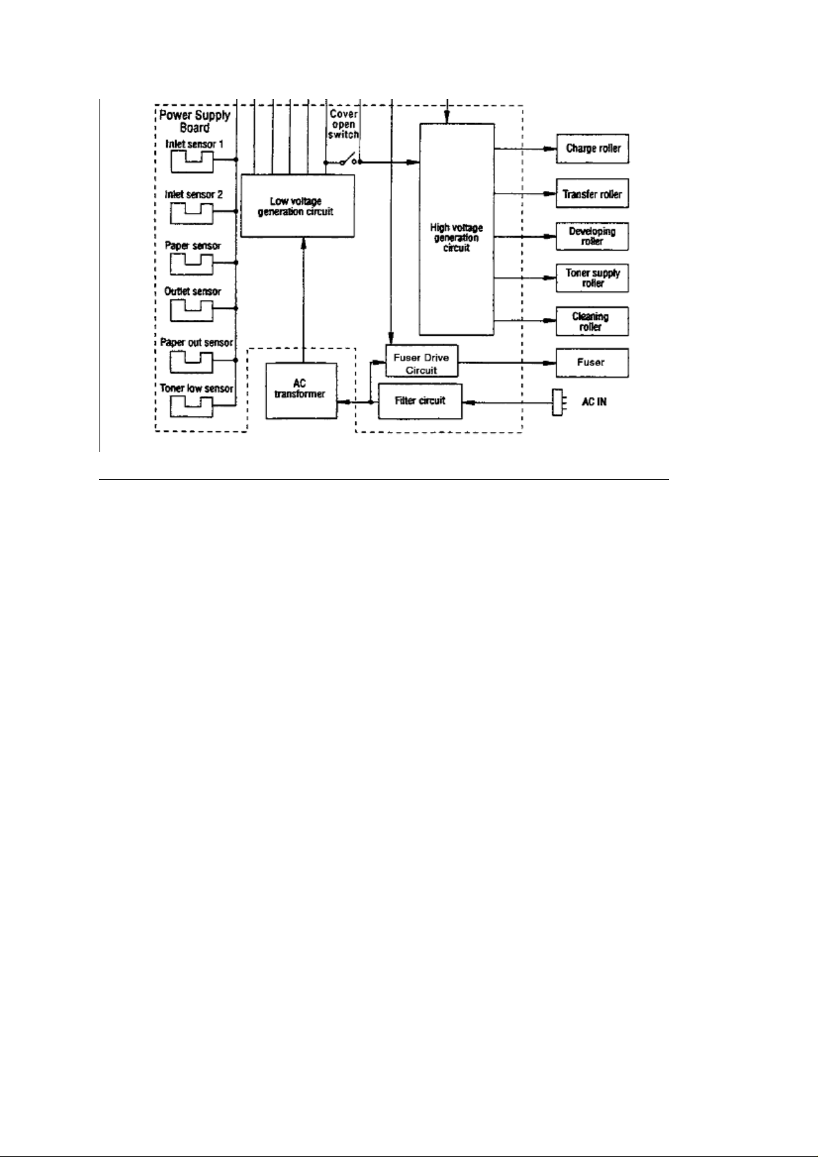
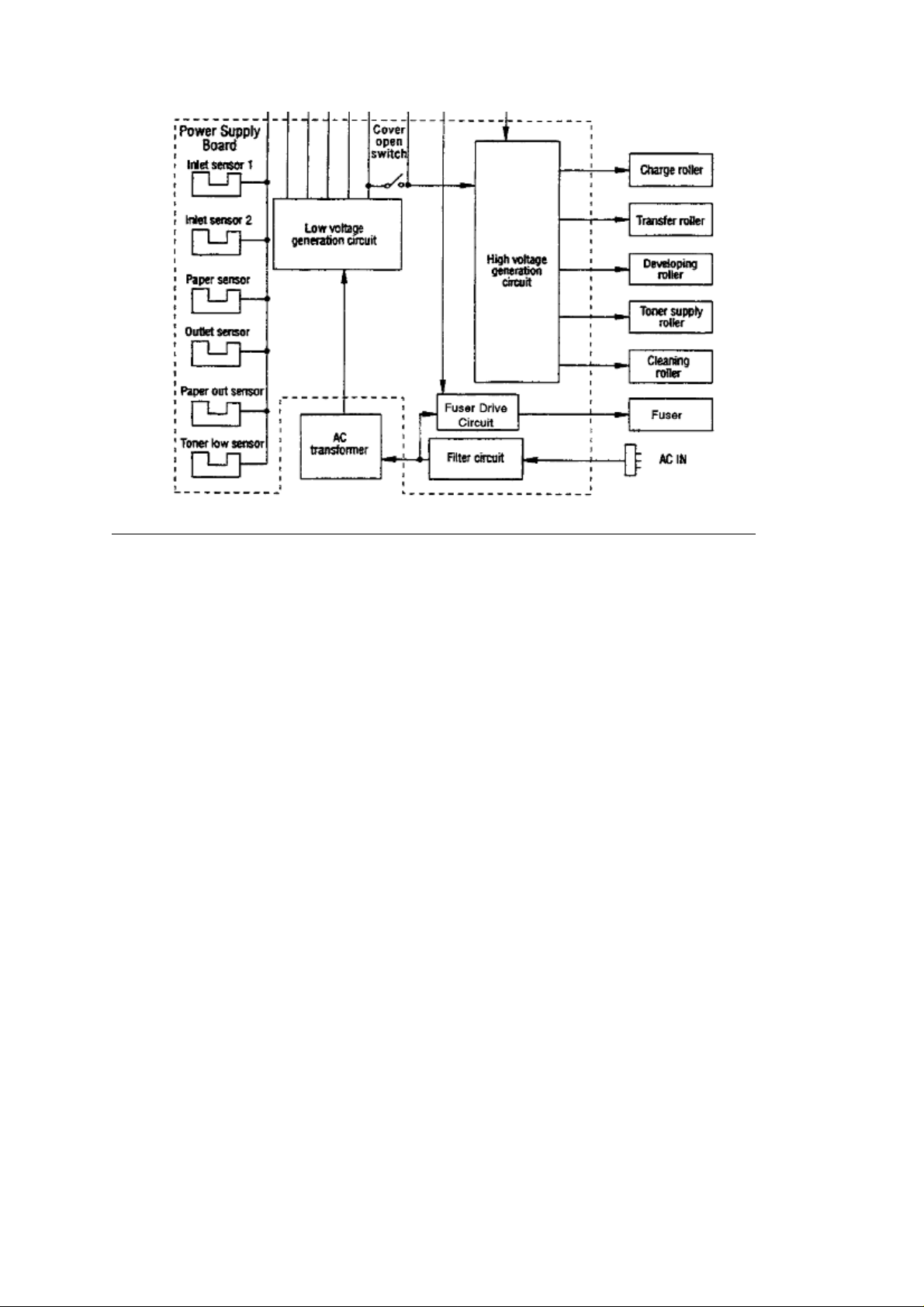
2.3.04 Power Supply Board
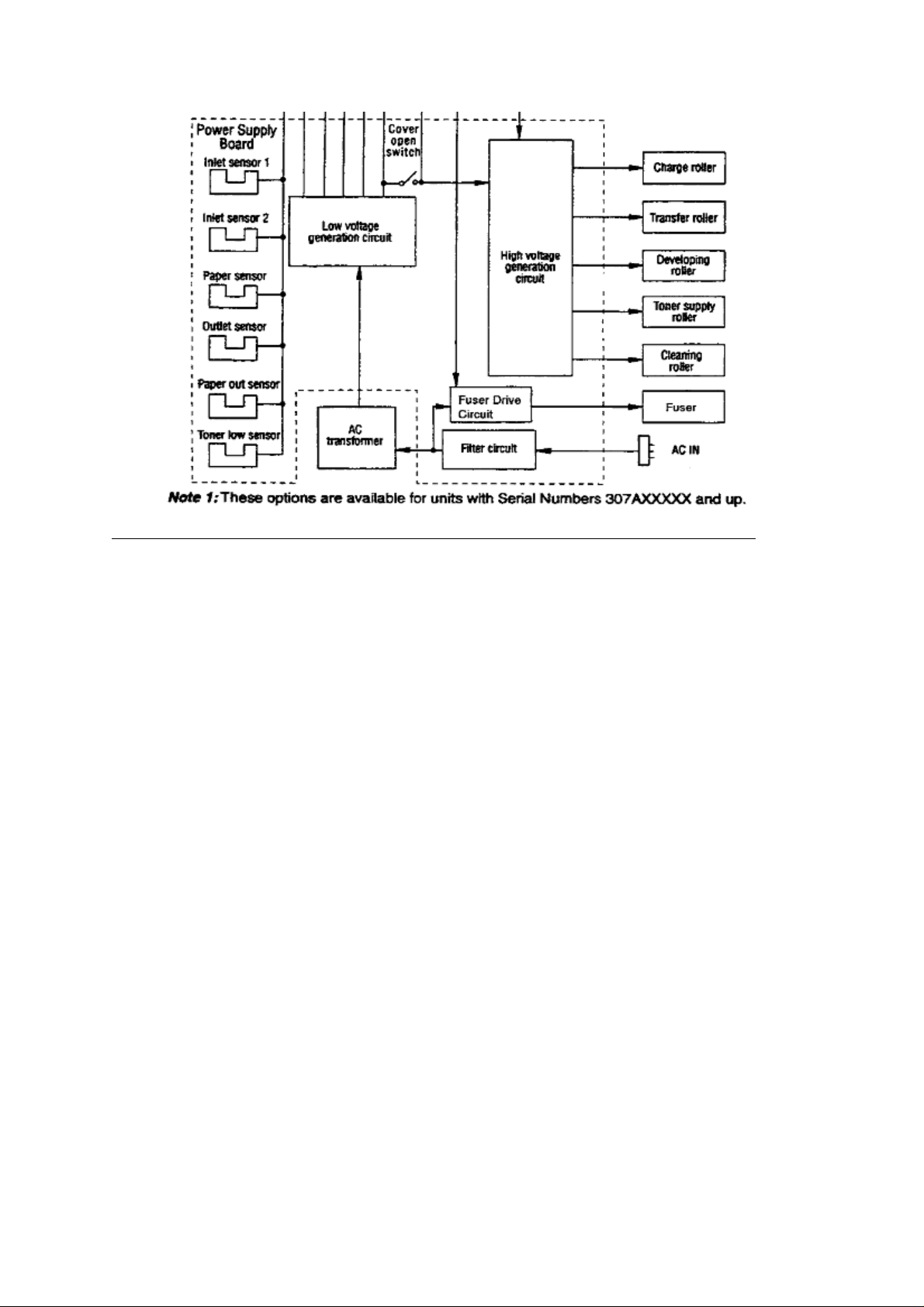
2.3.04 Power Supply Board
The power supply board consists of an AC filter circuit, a low-voltage power supply circuit,
a high-voltage power supply circuit, a fuser drive circuit and photosensors.
Low-Voltage Power Supply Circuit
The following voltages are generated by the low-voltage power supply circuit.
+ 5 vdc: Logic circuit supply voltage
+ 38 vdc: Motor / fan drive voltage and source voltage for the high-voltage supply
+ 8 vdc: RS232 line voltage
- 8 vdc: RS232 line voltage and analog circuit voltage
High-Voltage Power Supply Circuit
This circuit uses the + 38 vdc to generate voltages for the electrophotographic process.
The control sequence for enabling these voltages is issued by the main controller board.
When the cover-open state is detected, the + 38 vdc is turned off. Turning the +38 vdc
off disables all high-voltage outputs. The high-voltage power circuit generates the voltages
listed below.
- 1.3 Kvdc: applied to the charging roller
- 300 vdc: applied to the developing roller
- 450 vdc: applied to the toner supply roller
+ 1.6 Kvdc: applied to the transfer roller
+ 500 vdc: applied to the cleaning roller
OL400/410ex (96-01-30)

2.3.05 Fusing Unit
2.3.05 Fusing Unit
The fusing unit consists of a halogen lamp, a fusing roller, a thermistor and a thermostat.
An AC voltage from the power supply board is applied to the halogen lamp under the control
of the HEAT ON signal from the main controller board. This AC voltage is applied to the 400
watt halogen lamp. The main controller board controls the fusing roller temperature via the
thermistor, and regulates the fusing roller temperature at 150 degrees Celsius by switching
the lamp ON/OFF. If the roller temperature rises abnormally, the thermostat in the fusing unit
will cut the AC voltage supply OFF.
OL400/410ex (96-01-30)

2.3.06 Registration Motor
2.3.06 Registration Motor
The registration motor is a DC stepping motor (48 steps/rotation). This motor drives
the hopping roller and the registration roller via two one-way clutches. The direction
that the motor turns determines which clutch is activated.
OL400/410ex (96-01-30)

2.3.07 Drum Motor
2.3.07 Drum Motor
The drum motor is a DC stepping motor (48 steps/rotation).
This motor is the main drive motor of the printer.
OL400/410ex (96-01-30)

2.3.08 LED Head
2.3.08 LED Head
Image data for each dot line is received by shift registers and latch registers.
The 2,560 LEDs are activated to radiate the image data onto the image drum.
OL400/410ex (96-01-30)

**2.4 Printing Process General Information
2.4.01 PRINTING PROCESS General Information
Hopping and feeding are controlled by a single registration motor.
Turning the registration motor in the "A" direction drives the hopping roller.
Turning the registration motor in the "B" direction drives the registration roller.
The registration gear and hopping gear contain one-way bearings. Turning each
of these gears in the reverse direction will NOT turn the corresponding roller.
The following is too big!!!!
OL400/410ex (96-01-30)

OL400/410ex (96-01-30)

2.4.02 Hopping
2.4.02 Hopping
Hopping loads paper from the paper cassette.
During the hopping operation, the registration motor turns in a clockwise direction.
This motor drives the hopping roller, which in turn advances the paper until the inlet
sensor 1 switches ON. The registration gear turns, but the one-way bearing does not
allow the registration roller to turn.
After inlet sensor 1 switches ON, the paper is advanced a predetermined length (until
the paper reaches the registration roller).
OL400/410ex (96-01-30)

2.4.03 Feeding
2.4.03 Feeding
Feeding transports paper through the printer.
After the completion of hopping, the registration motor turns in a counter-clockwise
direction. This counter-clockwise motion drives the registration roller and advances
the paper. The hopping gear turns, but the one-way bearing does not allow the hopping
roller to turn.
OL400/410ex (96-01-30)

2.4.04 Charging
2.4.04 Charging
Charging applies -1.3 Kvdc to the charge roller. The charge roller contacts the image drum
surface.
The charge roller has two layers: a conductive layer and a surface protective layer. The
surface layer is flexible, which assures proper contact with the photosensitive drum.
The drum surface charges to approximately -750 vdc.
OL400/410ex (96-01-30)

2.4.05 Exposing
2.4.05 Exposing
The image drum has four layers.
- Carrier Transfer Layer (CTL)
- Carrier Generation Layer (CGL)
- Underlayer (UL)
- Aluminum Base
The CTL and CGL make up the organic photo conductor layer (OPC), which is about 20
micrometers (mm) thick.
When light from the LED head irradiates the image drum surface, the light energy generates
positive and negative carriers in the CGL. The positive carriers are moved to the CTL by an
electrical field acting on the image drum. The negative carriers flow into the aluminum layer
(ground).
OL400/410ex (96-01-30)

The positive carriers moved to the CTL combine with the negative charges on the image surface
(accumulated by the contact charge of the charge roller), lowering the potential on the image
drum surface. The resultant drop in the potential of the irradiated part of the image drum surface
forms an electrostatic latent image on it. The surface potential on this irradiated part of the image
drum is approximately -100 vdc.
OL400/410ex (96-01-30)

OL400/410ex (96-01-30)

2.4.06 Developing
2.4.06 Developing
The electrostatic latent image formed on the image drum surface is developed into a
visible image. Developing takes place when contact is made between the image drum
and the developing roller.
As the toner supply roller rotates, toner is absorbed into the sponge type roller material.
A charged particle will be attracted to a particle having a MORE POSITIVE charge than its own.
The developing roller surface is charged to -300 vdc and the toner supply roller is charged
to -450 vdc. Since the development roller is charged more positive than the toner supply roller,
the toner on the toner supply roller is attracted to the developing roller. The toner on the
developing roller contacts the doctor blade, forming a thin coat of toner on the developing
roller surface.
The exposed portion of the image drum contains a more positive charge than the development
roller (-100 vdc vs. -300 vdc). Therefore, toner is attracted to the exposed areas of the image
OL400/410ex (96-01-30)

drum, making the electrostatic latent image visible.
NOTE: The toner supply roller and the developing roller are supplied with the bias voltages
required during the developing process. The toner supply roller is charged to -450 vdc.
The developing roller is charged to -300vdc.
OL400/410ex (96-01-30)

2.4.07 Transfer
2.4.07 Transfer
The transfer roller is made of a conductive sponge material. The roller keeps the paper in
constant contact with the image drum. Paper is placed over the image drum surface. A
positive charge (opposite in polarity to the toner) is applied to the paper from the reverse
side.
A charged particle will be attracted to a particle having a MORE POSITIVE charge than
its own.
A high positive charge is applied to the transfer roller by the power supply board. This
induced charge (on the surface of the transfer roller) is transferred to the paper when
contact is made between the transfer roller and the paper. The lower side of the paper
is positively charged. The negatively charged toner (on the image drum) is transferred to
the upper side of the paper because of the positive charge on the lower side of the paper.
OL400/410ex (96-01-30)

2.4.08 Fusing
2.4.08 Fusing
After transfer, the toner image is fused to the paper by heat and pressure. The paper
passes between the fusing roller and the pressure roller. The fusing roller has a teflon
coating and contains a 400 watt halogen lamp. A thermistor (which contacts the fusing roller)
maintains the fusing roller temperature at approximately 150 degrees Celsius. A thermostat
cuts off the voltage supply to the lamp if there is an abnormal temperature rise.
The pressure roller provides 2.5 Kg of pressure. This is generated by the pressure springs at
each side of the roller.
OL400/410ex (96-01-30)

2.4.09 Cleaning
2.4.09 Cleaning
The image drum is cleaned at the end of transfer. The residual toner on the image
drum is attracted to the cleaning roller, which has a + 500 vdc static charge. This residual
toner is accumulated in the image drum cartridge until the drum is replaced.
OL400/410ex (96-01-30)

2.4.10 Printing
2.4.10 Printing
Refer to the Printing Process Diagram.
Printing is accomplished as follows.
Approximately - 1.3 Kvdc is supplied to the charge roller. This causes the drum to charge
to approximately - 750 vdc.
The LED head is turned ON by the printer control board in accordance with signals from the
main control board. This causes a latent electrostatic image to be formed on the surface of
the drum.
Through the development process, a toner image replaces the electrostatic image.
A + 1 Kvdc charge is applied to the transfer roller. This causes the toner image to be transferred
to the receive paper.
Heat and pressure cause the toner image to become fused to the receive paper. The 150
degree Centigrade fusing temperature is attained by turning a 400 watt halogen lamp ON.
The fusing temperature is controlled by a thermistor. In the event of a thermistor failure, a
temperature fuse will OPEN, turning off the quartz lamp, and preventing equipment damage.
The residual toner is removed from the drum.
OL400/410ex (96-01-30)

2.5 Sensors And Switches
2.5 SENSORS AND SWITCHES
OL400/410ex (96-01-30)

Sensor Location Diagram
Sensor Location Diagram
Top View
Side View
OL400/410ex (96-01-30)

OL400/410ex (96-01-30)

2.5.01 Paper Jam Detection
2.5.01 Paper Jam Detection
Paper jam detection monitors the location of paper when the printer is powered ON and during
printing. If any of the following jams are present, the printing process is interrupted and the
message PAPER JAM will be displayed on the LCD.
To return to the printing process, the paper jam condition MUST be cleared. This is accomplished
by opening the upper cover, clearing the jam, and closing the cover.
Paper Outlet Jam
This jam occurs if the paper does NOT pass over the outlet sensor within a pre-determined period
of time. However, the paper has already passed over the paper sensor.
Paper Size Error
The time interval between when the paper contacts the paper sensor and the outlet sensor
determines which size (length) paper is being used.
This error occurs if the paper size of the loaded paper differs by + 45 mm or more from the paper
size set by the menu.
Cover Open Switch
When the stacker cover is opened, the cover open microswitch on the power supply unit is
deactivated. This disables the + 38 vdc and the high voltage power supply circuit. As a result,
all high voltage outputs are interrupted. At the same time, the CVOPN signal is sent to the
main control board to notify it of the OFF state of the microswitch. The main control board
executes the cover open routine. The operation panel displays the message COVER OPEN.
OL400/410ex (96-01-30)

Paper Inlet Jam
Paper Inlet Jam
This jam occurs when either of the following situations occur.
When the printer is powered ON, paper is at inlet sensor 1.
After the hopping operation is attempted three times, the leading edge of the paper
does NOT reach inlet sensor 1.
Paper Inlet Jam Timing Diagram
OL400/410ex (96-01-30)

Paper Feed Jam
Paper Feed Jam
This jam occurs when either of the following conditions occur.
The paper does not pass over the paper sensor within a pre-determined period of time.
The leading part of the paper does not reach the outlet sensor within a pre-determined
period of time after the paper has passed over the paper sensor.
Paper Feed Jam Timing Diagram
OL400/410ex (96-01-30)

2.5.02 Toner Low Sensor
2.5.02 Toner Low Sensor
The toner well of the image drum cartridge contains a toner agitator. Whenever the image
drum rotates, the toner agitator attempts to turn. A spring clip in the bottom of the toner well
(along with the proper amount of toner) holds the agitator at the bottom of the well. However,
when toner is distributed unevenly or an insufficient amount of toner is in the well, the toner
agitator will rotate. Therefore, as long as the toner well contains an adequate supply of evenly
distributed toner, the toner agitator will not rotate.
The toner sensor plate has a magnet embedded in it. Whenever the toner agitator is positioned
at the bottom of the toner well, the toner sensor plate is magnetically attracted to the toner
agitator. This causes the toner sensor plate to be lifted from the path of the toner sensor.
During a low toner condition, the toner agitator will rotate continuously. This causes the toner
sensor to turn ON / OFF as the image drum rotates. The operator panel will then display the
TONER LOW message.
During an unevenly distributed toner condition, the toner agitator will rotate until the toner is
distributed sufficiently. This causes the toner sensor to turn ON / OFF for only a few image
drum rotations. The operator panel will not display an error message since this is normal printer
operation.
If the toner sensor remains activated (ON), the operator panel will display the TONER SNS
message.
Customers may experience a "TONER SNS" or "TONER LOW" message with a brand new printer.
This may occur even though a new toner cartridge and drum have been installed.
This can occur for the first 30 pages. Between 30 and 200 pages, the CPU will turn OFF the
toner sensor. This will eliminate the message on the LCD. After 200 pages, the printer will
begin checking for proper operation of the toner sensor flag.
Customers should use the printers for at least 30 pages. The "TONER SNS" or "TONER LOW"
messages do not cause any print quality problems. The unit is in NO danger of suffering any
damage. If the problem persists for more than thirty pages, customers are directed to contact
a service center for warranty repair. This information is documented in TSB 5604(
).
OL400/410ex (96-01-30)

2.5.03 Paper Path
2.5.03 Paper Path
General Information
The automatic and manual feed paths are different. In addition, the path will change if the
paper is ejected face up or face down. Paper fed from the paper tray (automatic feed) and
ejected face down will follow an "S" path. The path with the least amount of turns is a
manual feed, face up ejection.
Automatic Feed
Load paper into the tray. The side to be printed on should be facing DOWN.
The leading edge of the paper should face the FRONT of the printer. Refer to either the
face down or the face up section for further paper path details.
Manual Feed
Manually load the paper into the unit. The side to be printed on should be facing UP.
The leading edge of the paper should face the BACK of the printer. Refer to either the
face down or the face up section for further paper path details.
Face Down
The hopping roller picks up the paper. The hopping roller transports the paper to the registration
roller. The registration roller transports the paper to the image drum. Then, the paper passes
between the fusing roller (on top) and the pressure roller (on the bottom). The paper is then
routed upward and is ejected from inside the unit.
Face Up
The hopping roller picks up the paper. The hopping roller transports the paper to the registration
roller. The registration roller transports the paper to the image drum. Then, the paper passes
between the fusing roller (on top) and the pressure roller (on the bottom). The paper is then
ejected from the inside of the unit.
OL400/410ex (96-01-30)

OL400/410ex (96-01-30)

Chapter 3
3.1.01 Maintenance General Information
3.1.01 General Information
This section lists the parts replacement, adjustment, cleaning, lubrication, and shipping
procedures.
Disassembly should not be performed unless absolutely necessary. NEVER perform
disassembly on a malfunctioning unit until you have followed the failure analysis
procedures in Section Four of this Service Handbook.
Follow the procedures listed in Adjustments and Service Settings. Adjustments may be
required when either consumables or parts are replaced. Failure to perform these
procedures could result in unnecessary service calls.
Cleaning procedures must be performed correctly if high print quality is to be achieved.
OL400/410ex (96-01-30)

3.3 Adjustments And Service Settings
3.3 ADJUSTMENTS AND SERVICE SETTINGS
General Information
This section contains the procedures for checking and resetting counters and performing
adjustments and service settings. These procedures may be required when replacing either
consumables or parts. The disassembly / assembly procedures list the required adjustments
and refer you to this section. Failure to perform these procedures may result in unnecessary
service calls.
The adjustments and service settings are accomplished through the operator panel. Three
different maintenance modes are used: user, system, and engine. Service setting changes
are saved in the EEPROM located on the main controller board.
NOTE: End users should NOT access the system or engine maintenance modes.
OL400/410ex (96-01-30)

3.3.01 User's Maintenance Mode
3.3.01 User's Maintenance Mode
General Information
This maintenance mode allows the user to access the following functions.
- Menu Reset..................................... (
- Hex Dump....................................... (
- Drum Counter Reset......................... (
- Op Menu......................................... (
- X-Adjust (OL410e / OL410e-PS)......... (
- Y-Adjust (OL410e / OL410e-PS)......... (
User's Maintenance Mode Procedure
To enter user maintenance mode, perform the following procedure.
- Close the stacker cover.
- Install the paper cassette tray.
- Clear all error messages displayed on the operator panel.
- Power OFF the unit.
- Press and hold MENU 1 / Menu 2 while powering ON the unit.
Continue to hold through both panel message displays.
The operator panel displays the following for approximately two seconds.
88888888
88888888
- Release MENU 1 / Menu 2 once the operator panel displays
USER MNT
- Press MENU 1 / Menu 2.
The operator panel displays the following message.
MENU
RESET
)
)
)
)
)
)
7) Press MENU 1 / Menu 2.
The operator panel displays the following message.
8) Press MENU 1 / Menu 2.
The operator panel displays the following message.
9) Press MENU 1 / Menu 2.
The operator panel displays the following message.
For OL410 / OL410e-PS models only
10) Press MENU 1 / Menu 2.
The operator panel displays the following message.
11) Press MENU 1 / Menu 2.
OL400/410ex (96-01-30)
HEX DUMP
DRUM CNT
RESET
OP MENU
ENABLE
X ADJUST
0 mm *

The operator panel displays the following message.
Y ADJUST
0 mm *
NOTE:
- To work with any of the user maintenance mode items, press ENTER / Copies.
- Press LAST - / Paper Size or NEXT + / Demo to move through the settings for
the user maintenance mode items.
OL400/410ex (96-01-30)

Menu Reset / Menu Print
Menu Reset / Menu Print
CAUTION:
Menu Reset returns ALL menu level 1 settings to factory defaults.
ALL customized menu level 1 settings will be lost.
ALWAYS print the menu before doing a menu reset.
Double Click to see Menu Settings Level 1................ (
Menu Settings Level 2................ (
Sample Page OL400e................ (
Sample Page OL410e................ (
Sample Page OL410e-PS........... (
Procedure - Menu Print
To print the menu, follow this procedure.
1) Press ON-LINE to take the printer OFF-LINE.
2) Press PRINT MENU / Print Fonts to print the menu.
Procedure - Menu Reset
To reset the menu, perform the following procedure.
CAUTION:
Menu Reset returns ALL menu level 1 settings to factory defaults.
ALL customized menu level 1 settings will be lost. ALWAYS print
the menu before doing a menu reset.
1) Close the stacker cover.
2) Install the paper cassette tray.
3) Clear all error messages displayed on the operator panel.
4) Power OFF the unit.
5) Press and hold MENU 1 / Menu 2 while powering ON the unit.
The operator panel displays the following for approximately two seconds.
88888888
88888888
The operator panel displays the following message.
USER MNT
)
)
)
)
)
6) Press MENU 1 / Menu 2.
The operator panel displays the following message.
MENU
RESET
7) Press ENTER / Copies.
The operator panel displays the following message for approximately 15 seconds.
WARM UP
8) The unit will then go ON-LINE.
The operator panel displays the following message.
ON-LINE ON-LINE ON-LINE
HPIIP HPIII ADOBE PS
(OL400e) (OL410e) (OL410e/PS)
OL400/410ex (96-01-30)

Menu Settings - Level 1
Menu Settings - Level 1
Factory defaults are printed in
Category Items Options Explanation
PRINTER
LANGUAGE
(OL400e only)
PRINTER
LANGUAGE
(OL410e only)
PRINTER
LANGUAGE
(OL410e-PS only)
TRAY SELECT PAPER IN
EMULATE HPIIP
EMULATE HPIII (OL410e)
EMULATE Adobe PS
.
bold
(OL410e-PS)
TRAY 1
TRAY 2
Appears if
installed
MANUAL Select manual paper
Select paper tray.
Select second paper
tray
feed.
AUTOTRAY
if tray 2 installed
PAPER SIZE TRAY 1
Appears
FEEDER
installed
, OFF
ON
Appears if
LETTER
EXEC
LEGAL 14
LEGAL 13
A4 SIZE
A5 SIZE
A6 SIZE
B5 SIZE
FREE
Select feeder.
Set On, printer will
switch to second tray
when first tray is
empty.
Select paper size in
tray 1.
8.5" X 11"
7.25" X 10.5"
8.5" X 14"
(with optional legal
tray)
8.5" X 13"
(with optional legal
tray)
210 mm 297 mm
148 mm 210 mm
105 mm X 148 mm
176 mm X 250 mm
Allows printing on
custom size paper
OL400/410ex (96-01-30)

TRAY 2
installed
Appears if
LETTER
LEGAL 14, LEGAL
13, A4 SIZE, A5
SIZE, A6 SIZE, B5
SIZE, FREE
, EXEC,
Select paper size in
tray 2 if installed.
MANUAL
FEEDER
installed
MEDIA TYPE TRAY 1
MANUAL
Appears if
LETTER
LEGAL 14, LEGAL
13, A4 SIZE, A5
SIZE, A6 SIZE, B5
SIZE, FREE
COM-10
MONARCH, DL ENV,
C5 ENV, LETTER,
EXEC, LEGAL 14,
LEGAL 13, A4 SIZE,
A5 SIZE, A6 SIZE,
B5 SIZE, FREE
MEDIUM,
LIGHT
, EXEC,
COM-10
MONARCH
DL ENV
,
Select paper size for
manual feed.
4.12" X 9.50"
Envelope
3.87" X 7.50"
Envelope
110 mm X 220 mm
Envelope
Select
envelope/paper size
in feeder if installed
Normal setting for
20-28lb paper.
Select LIGHT if
16-20lb paper
wrinkles or curls
COPIES 1 to 99 Select number of
copies to print for
each document
FONTS & SYMBOLS FONT SRC
RESDENT
Appears if installed,
DLLSOFT
, CARD
Appears if
Select font source.
loaded
FONT NO
I000
to I013,
I020 (OL410e)
I000
to
Select font by ID
number (see font print
sample). Prefix
indicates font source:
I=internal (resident);
C=card; S=soft font.
OL400/410ex (96-01-30)

FONT CPI
Appears if selected
font is scalable/fixed
spaced
(OL410e)
10.00
, 0.44 to 99.99
Select number of
characters printed in
a horizontal inch
(pitch) when scalable
font with fixed
spacing is selected.
(0.01 mm
increments).
Character height
(point size) adjusts
accordingly.
FONT HGT
Appears if selected
font is
scalable/proportional
spaced
SYMBOL ROMAN-8 Roman-8 is the
HP CART
410e-PS)
PAGE LAYOUT ORIENT
LINES/PG
(OL410e)
(OL410E &
12.00
, 4.00 to 999.75
NONE
, F,B
PORTRT
60 LNS
LNS
, 5 to 128
Select point size
(height) of characters
when scalable font
with proportional
spacing is selected.
(0.25 mm
increments).
Horizontal spacing
adjusts accordingly.
standard HP set.
HP font cartridge
designations. Select
F or B to agree with
software or select
NONE.
, LANDSCP
Select number of
lines on page.
A4 WIDTH
BLNKSKIP
OL400/410ex (96-01-30)
78 COL
OFF
, ON
, 80 COL
Use this option for A4
size paper to select
78 columns or
condense 80 columns
so characters will fit
on a line.
Set ON printer will
ignore FF code when
buffer is empty.
(Sometimes Word for
Windows will print an
extra blank page.)

HOST I/F AUTO I/F,
PARALLEL, RS232C
Adobe-PS
Local Talk
or RS-422
Select active
interface.
OL400/410ex (96-01-30)

Menu Settings - Level 2
Menu Settings - Level 2
Factory defaults are printed in
Category Items Options Explanation
PRINT MODE
bold.
Select printing mode.
(OL410e and
OL410e-PS)
OKI600 requires
OL410e driver. HPIII
Emulation supports
OKI300
widens/blackens
characters and
graphic dots so edges
appear more crisp and
less jagged
Reserves area in
memory for page size
selected; eliminates
print overuns
MEMORY USAGE
(OL400e and
OL410e-PS Only)
SMOOTHNG Appears
if PRINT MODE is
OKI600
PAGEPROT Appears
if optional RAM is
installed
OKI600,
OKI300
MEDIUM, DARK Smoothing
Off
, Letter, Legal, A4
PAGE BUF (OL410e),
OKI600
300DPI
, 360KB to
AUTO
3.96MB, FUL LTR
Requires 5MB RAM,
FUL A4 Requires 5MB
RAM
, 180KB to
AUTO
900KB, FUL LTR, FUL
A4, FUL LGL
Reserve work area in
memory for building
image insuring that
entire page prints;
eliminates print
overuns. AUTO allows
printer to maximize
RAM areas for best
results. Other areas
may be customized if
file size of graphic
image is known
OL400/410ex (96-01-30)

REC BUFF AUTO (OL410e), 8KB,
20KB, 50KB, 100KB,
1MB
Select amount of
memory devoted to
holding received data;
larger setting improves
computer return to
application time.
OL400e requires
optional RAM for 1 MB
setting
AUTO
OPERATION
FONT PROT OKI600
AUTO
, OFF, 100 KB
to 3.1MB
300DPI AUTO, OFF, 100KB to
3.6MB
AUTOCONT
OFF
, ON
Reserves a section of
memory for
downloading fonts;
improves printing
speed by saving
previously created
fonts. Will take
memory away from
total print buffer and
REC BUFF
If ON, software or
data error will cause
printer to display error
message then
continue to print; Set
Off, printer will stop
printing; press
RECOVER to
continue.
DARKNESS
CONTROL
AUTOEJCT
DARKNESS
OFF
, 15 SEC, 30
SEC, 1 MIN
0
, +1, +2, -2, -1
When set to other
than Off: if printer
doesn't receive data
within the set time (15
Sec, 30 Sec, or 1
Min), current page will
print and eject. Meant
for use with software
that doesn't issue
Form Feed command
at end of last page.
When Off, printer
won't print last page
without a Form Feed
Control print density.
Negative values
lighten, positive values
darken.
OL400/410ex (96-01-30)

POWER SAVING PWR SAVE
ENABLE
, DISABLE
Enable: reduces
power consumption. 8
minutes after printer
stops receiving data
fuser heating element
shuts off; after 12
additional minutes fan
shuts off. When printer
receives more data,
fuser warms up before
printing begins.
Disable: fuser and fan
are always on, printer
is ready to print at all
times
TONER SAVING
(OL400e)
PARALLEL I/F I-PRIME
RS232C SERIAL FLOW CTL
BAUDRATE
TNR SAVE DISABLE
MEDIUM, LIGHT
OFF
, ON
DTR HI
, DTR LO,
XONXOFF,
RBSTXON
9600
, 19200, 300,
600, 1200, 2400, 4800
Use this feature to
,
conserve toner and
reduce printing costs
when you are printing
rough drafts or proof
copies.
Medium reduces toner
by 30%, light reduces
toner by 50%
Set On, I-Prime signal
resets printer. Set
OFF, or HOST I/F is
AUTO IF, printer
ignores signal
Select serial protocol.
Select transmission
rate in bits per second
(bps)
DATABITS
PARITY
MIN BUSY
OL400/410ex (96-01-30)
8 BITS
NONE,
, 7 BITS
EVEN, ODD
200 mSEC
, 1 SEC
Select serial interface
data bit format.
Select serial interface
parity type.
Set length of busy
signal when
Ready/Busy (DTR)
protocol is selected.

LANGUAGE ENGLISH,
DEUTSCH,
FRANCIS,
ITLIANO,
CASTLAN,
SVENSKA,
NORSK,
DANSK,
NEDERL,
PORTUGUÊS
Select language
displayed.
German
French
Italian
Spanish
Swedish
Norwegian
Danish
Dutch
Portuguese
OL400/410ex (96-01-30)

Sample Menu - OL400E
Sample Menu - OL400e
OL400/410ex (96-01-30)

Sample Menu - OL410E
Sample Menu - OL410e
OL400/410ex (96-01-30)

Sample Menu - OL410E/PS
Sample Menu - OL410e/PS
OL400/410ex (96-01-30)

OL400/410ex (96-01-30)

Hex Dump
Hex Dump
General Information
Data received by the printer is converted to hexadecimal codes and printed
when the printer is in HEX DUMP mode.
If the amount of data received is more than one page, printing will
automatically activate.
If the amount of data received is less than one page, you may have to manually
activate printing.
To print the page, you can do one of the following procedures.
- Press ON-LINE to place the printer OFF-LINE.
- Press FORM FEED / Tray Select.
or
- Set AUTO EJECT to ON in the menu.
Procedure
To enter hex dump mode, perform the following procedure.
- Close the stacker cover.
- Install the paper cassette tray.
- Clear all error messages displayed on the operator panel.
- Power OFF the unit.
- Press and hold MENU 1 / Menu 2 while powering ON the unit.
The operator panel displays the following for approximately two seconds.
88888888
88888888
- Release MENU 1 / Menu 2 once the operator panel displays the following message.
- Press MENU 1 / Menu 2.
The operator panel displays the following message.
- Press MENU 1 / Menu 2.
The operator panel displays the following message.
- Press ENTER / Copies
The operator panel displays the following message for approximately 15 seconds.
- The unit will go ON-LINE.
The operator panel displays the following message.
To exit Hex Dump, power OFF the unit.
Hexadecimal Codes (US ASCII)
USER MNT
MENU
RESET
HEX DUMP
WARM UP
ON-LINE
HEX DUMP
OL400/410ex (96-01-30)

OL400/410ex (96-01-30)

Drum Counter Reset
Drum Counter Reset
General Information
The drum counter should be reset when the image drum is replaced.
This message will be displayed on the operator panel when the image drum
should be replaced.
CHG DRUM
The counter MUST be reset to clear this message.
The drum count is NOT the same as the page count or the drum count total.
Procedure
To view the drum count, perform the following procedure.
- Close the stacker cover.
- Install the paper cassette tray.
- Clear all error messages displayed on the operator panel.
- Power OFF the unit.
- Press and hold MENU 1 / Menu 2 while powering ON the unit.
The operator panel displays the following for approximately two seconds.
88888888
88888888
- Release MENU 1 / Menu 2 once the operator panel displays the following message.
USER MNT
- Press MENU 1 / Menu 2.
- The operator panel displays the following message.
MENU
RESET
- Press MENU 1 / Menu 2.
The operator panel displays the following message.
HEX DUMP
- Press MENU 1 / Menu 2.
The operator panel displays the following message.
DRUM CNT
RESET
- Press ENTER / Copies.
The operator panel displays the following message.
DRUM CNT
RESETTING
- The unit will go ON-LINE.
- The operator panel displays the following message.
OL400/410ex (96-01-30)

ON-LINE ON-LINE ON-LINE
HPIIP HPIII ADOBE PS
(OL400e) (OL410e) (OL410e/PS)
OL400/410ex (96-01-30)

Operator Panel Menu Enable / Disable
Operator Panel Menu Enable / Disable
General Information
This function enables or disables the operator panel menu functions.
When this function is DISABLED, all control panel buttons except ON-LINE are disabled.
The default is for the operator panel to be enabled.
Procedure
To enable or disable the operator menu, perform the following procedure.
- Close the stacker cover.
- Install the paper cassette tray.
- Clear all error messages displayed on the operator panel.
- Power OFF the unit.
- Press and hold MENU 1 / Menu 2 while powering ON the unit.
The operator panel displays the following for approximately two seconds.
88888888
88888888
- Release MENU 1 / Menu 2 once the operator panel displays the following message.
USER MNT
- Press MENU 1 / Menu 2.
The operator panel displays the following message.
MENU
RESET
- Press MENU 1 / Menu 2.
The operator panel displays the following message.
HEX DUMP
- Press MENU 1 / Menu 2.
The operator panel displays the following message.
DRUM CNT
RESET
- Press MENU 1 / Menu 2.
The operator panel displays the following message.
OP MENU
ENABLE
- Press ENTER / Copies
The operator panel displays the following message.
OP MENU
ENABLE
An asterisk will follow the word ENABLE if the op menu is enabled.
- Press LAST - / Paper Size or NEXT + / Demo to toggle between ENABLE and DISABLE.
The operator panel displays the following message.
OL400/410ex (96-01-30)
OP MENU OP MENU
ENABLE or DISABLE

An asterisk will follow the word ENABLE or DISABLE to show the selection.
- Press ENTER / Copies to select the setting.
An asterisk will follow the word ENABLE or DISABLE to show the selection.
- Press ON-LINE to save the setting and exit the user maintenance mode.
The operator panel displays the following message for approximately 15 seconds.
WARM UP
The operator panel displays the following message.
ON-LINE ON-LINE ON-LINE
HPIIP HPIII ADOBE PS
(OL400e) (OL410e) (OL410e/PS)
OL400/410ex (96-01-30)
 Loading...