

Page 1
Page: 1
Service Guide OL600e/610e/610ePS
Chapter 0 About This Manual
OL600e / OL610e / OL610ePS Series
LED Page Printers
Adobe Acrobat printable reference
copy of the OKIDATA Service Training Manual.
09/17/97
Note: This Adobe Acrobat version of the Okidata Service Training Manual was built with the
pictures rendered at 300 dpi, which is ideal for printing, but does not view on most
displays well.
Copyright 1997, Okidata, Division of OKI America, Inc. All rights reserved. See the OKIDATA Business
Partner Exchange (BPX) for any updates to this material. (http://bpx.okidata.com)
Page 2

Table of Contents Page
Service Guide OL600e/610e/610ePS
0 About This Manual
Front Cover 1
Trademark Information 2
Preface 3
1 Configuration
1.1 System Configuration 4
1.2 Printer Configuration 5
1.3 Optional Configuration 6
1.4 Specification 7
1.5 Safety Standards - 1.5.1 Certification Label 8
....1.5.2 Warning Labels 9
....1.5.3 Warning/Caution Markings 10
2 Operation Description
Operation Description 11
....Figure 2-2 OL610e Block Diagram 12
....Figure 2-3 OL610e/PS Block Diagram 13
2.1 Control Board 14
2.2 PS Board (OL610e/PS) 15
2.3 Power Supply Board 16
2.4 Electrophotographic Process - 2.4.1 Electrophotographic
Process Mechanism
....2.4.2 Electrophotographic Process 18
....2.4.3 Process Operation Descriptions - Hopping and
Feeding
........Charging 20
........Exposure 21
........Developing 22
........Transfer 23
........Fusing 24
........Cleaning 25
........Cleaning of rollers 26
2.5 Paper Jam Detection 27
2.6 Cover Open 28
2.7 Toner Low Detection 29
3 Parts Replacement
3.1 Precautions for Parts Replacement 30
3.2 Parts Layout - [Lower base unit] 31
....Upper cover unit 32
....Base unit 33
3.3 How to Change Parts 34
....3.3.1 Upper Cover 35
....3.3.2 Stacker 36
17
19
Page 3

Table of Contents Page
....3.3.3 LED Head 37
....3.3.4 Eject Roller Assy 38
....3.3.5 Pulse Motor (Main) 39
....3.3.6 Pulse Motor (Registration) 40
....3.3.7 Lower Base Unit 41
....3.3.8 Motor Assy 42
....3.3.9 Hopping Roller Assy 43
....3.3.10 Stacker Cover Assy 44
....3.3.11 Registration Roller 45
....3.3.12 Transfer Roller 46
....3.3.13 Fusing Unit Assy 47
....3.3.14 Fusing Pressure Roller 48
....3.3.15 Sensor Plate (Inlet) 49
....3.3.16 Toner Sensor (Adhesion) 50
....3.3.17 Sensor Plate (Outlet) 51
....3.3.18 Manual Feed Guide Assy 52
....3.3.19 Sensor Plate (Paper Supply) 53
....3.3.20 Main Control PCB 54
....3.3.21 Power Supply Board and Contact Assy 55
....3.3.22 Transformer 56
....3.3.23 Cassette Guide L 57
....3.3.24 Cassette Guide R 58
4 Adjustments
4.1 Maintenance Menus and Functions 59
4.2 Adjustment When Replacing a Part 60
5 Periodical Maintenance
5.1 Periodical Replacement Parts 61
5.2 Cleaning 62
5.3 Lubrication 63
6 Troubleshooting
6. Troubleshooting - 6.1 Troubleshooting Tips 64
6.2 Points to Check before Correcting Image Problems 65
6.3 Tips for Correcting Image Problems 66
6.4 Preparation for Troubleshooting 67
6.5 Troubleshooting Flow 68
....6.5.1 Status Message/Trouble List 69
........Status Message/Trouble List - Continued 70
........Status Message/Trouble List - Continued 71
....6.5.2 Message Troubleshooting 72
........1 The printer does not work normally after the power is
turned on.
........[JAM error] 2-1 Paper input jam 74
........[JAM error] 2-2 Paper feed jam 75
........[JAM error] 2-3 Paper exit jam 76
73
Page 4

Table of Contents Page
........3 Paper size error 77
........4 Fusing unit error (ERROR 71) (ERROR 72) (ERROR
73)
........5 Fan error (ERROR 70) 79
....6.5.3 Image Troubleshooting 80
........1 Images are light or blurred entirely. 81
........2 Dark background density 82
........3 Blank paper is output. 83
........4 Black vertical belts or stripes 84
........5 Cyclic error 85
........6 Print voids 86
........7 Poor fusing 87
........8 White vertical belts or streaks 88
7 Wiring Diagrams
7.1 Interconnect Signal Diagram 89
7.2 PCB Layout and Connector Signal List - (1) Control Board 90
....(2) Power Supply Board 91
....(3) PS Board (LQ8A- ) (OL610e/PS) 92
........CN1 Pin Assignment To Fan motor 93
........CN2 Pin Assignment To Drum motor 94
........CN3 Pin Assignment To Registration motor 95
........CN4 Pin Assignment To LED head 96
........CN6 Pin Assignment To Option feeder 97
........Power Pin Assignment 98
........CN8 Pin Assignment 99
........CN11 Pin Assignment 100
........PS Board (OL610e/PS) 101
........PS Board (OL610e/PS) 102
7.3 Resistance Check 103
7.4 Short Plug Setting 104
8 Parts List
8.1 Lower Base Unit 105
8.2 Upper cover unit 106
8.3 Base unit 107
A Centronics Parallel Interface
Centronics Parallel Interface 108
B Local Talk (RS422) Serial Interface (OL610e/PS only)
Appendix B LOCALTALK (RS422) SERIAL INTERFACE
(OL610e/PS only)
....a) LocalTalk « RS422 switching 110
....b) RS422 I/F parameter setting 111
C Software Diagnostics and Adjustments
1. Maintenance Menus OL610e/PS 112
....1.2 System Maintenance Menu 113
78
109
Page 5

Table of Contents Page
....1.3 Engine Maintenance Menu 114
....1.4 Factory User Setting Operation 115
2. DOS Software Operating PanelOL600e & OL610e - 2.1
Settings Tab
....2.2 Service Tab ? 117
D Multi-Purpose Feeder Maintenance PREFACE
Multi-Purpose Feeder Maintenance Preface 118
Table of Contents 119
1. OUTLINE 120
2. MECHANISM DESCRIPTION 121
3. PARTS REPLACEMENT - 3.1 Precautions Concerning Parts
Replacement
....3.2 Parts Layout 123
....3.3 Parts Replacement Methods - 3.3.1 Link 124
........3.3.2 Separator 125
........3.3.3 OLEV-11 PCB 126
........3.3.4 Pulse Motor 127
........3.3.5 Planet Gear 128
........3.3.6 Roller-A and -B 129
4. TROUBLESHOOTING - 4.1 Precautions Prior to
Troubleshooting
....4.2 Preparations for Troubleshooting 131
....4.3 Troubleshooting Method 132
5. CONNECTION DIAGRAM 133
6. PARTS LIST 134
E High Capacity Second Paper Feeder Maintenance
High Capacity Second Paper Feeder Maintenance - Preface 135
Table of Contents 136
1. OUTLINE 137
2. MECHANISM DESCRIPTION 138
3. PARTS REPLACEMENT - 3.1 Precautions Concerning Parts
Replacement
....3.2 Parts Layout 140
....3.3 Parts Replacement Methods - 3.3.1 Pulse Motor
(Hopping)
........3.3.2 OLEV-12 PCB 142
........3.3.3 Hopping Roller Shaft Assembly and One-way Clutch
Gear
4. TROUBLESHOOTING - 4.1 Precautions Prior to
Troubleshooting
....4.2 Preparations for Troubleshooting 145
....4.3 Troubleshooting Method 146
5. CONNECTION DIAGRAM 147
6. PARTS LIST 148
116
122
130
139
141
143
144
Page 6

Table of Contents Page
............Wrong Part Number : Bill Healey/OKI_ELECTRIC/US;
02/22/96
149
Page 7

Page: 2
Service Guide OL600e/610e/610ePS
Chapter 0 About This Manual
HP and LaserJet are registered trademarks of Hewlett-Packard Company. Adobe and PostScript are
trademarks of Adobe Systems Incorporated, which may be registered in certain jurisdictions. LocalTalk is
a registered trademark of Apple Computer Inc. Centronics is a registered trademark of Centronics Data
Corporation. OKIDATA is a registered trademark of Oki America, Inc. OKIDATA est une marque déposée
de Oki America, Inc.
Copyright 1997, Okidata, Division of OKI America, Inc. All rights reserved. See the OKIDATA Business
Partner Exchange (BPX) for any updates to this material. (http://bpx.okidata.com)
Page 8

Page: 3
Service Guide OL600e/610e/610ePS
Chapter 0 About This Manual
Preface
This Service Manual describes the field maintenance procedures for OL600e, OL610e and OL610e/PS
LED Page Printers
This manual is written for use by service personnel. Refer to the Printer Handbook for handling and
operating procedures.
Copyright 1997, Okidata, Division of OKI America, Inc. All rights reserved. See the OKIDATA Business
Partner Exchange (BPX) for any updates to this material. (http://bpx.okidata.com)
Page 9

Page: 4
Service Guide OL600e/610e/610ePS
Chapter 1 Configuration
1.1 System Configuration
OL600e, OL610e and OL610e/PS consist of control and engine blocks in the standard configuration, as
shown in Figure 1-1.
In addition, the options marked with an asterisk (*) are available.
Page 10
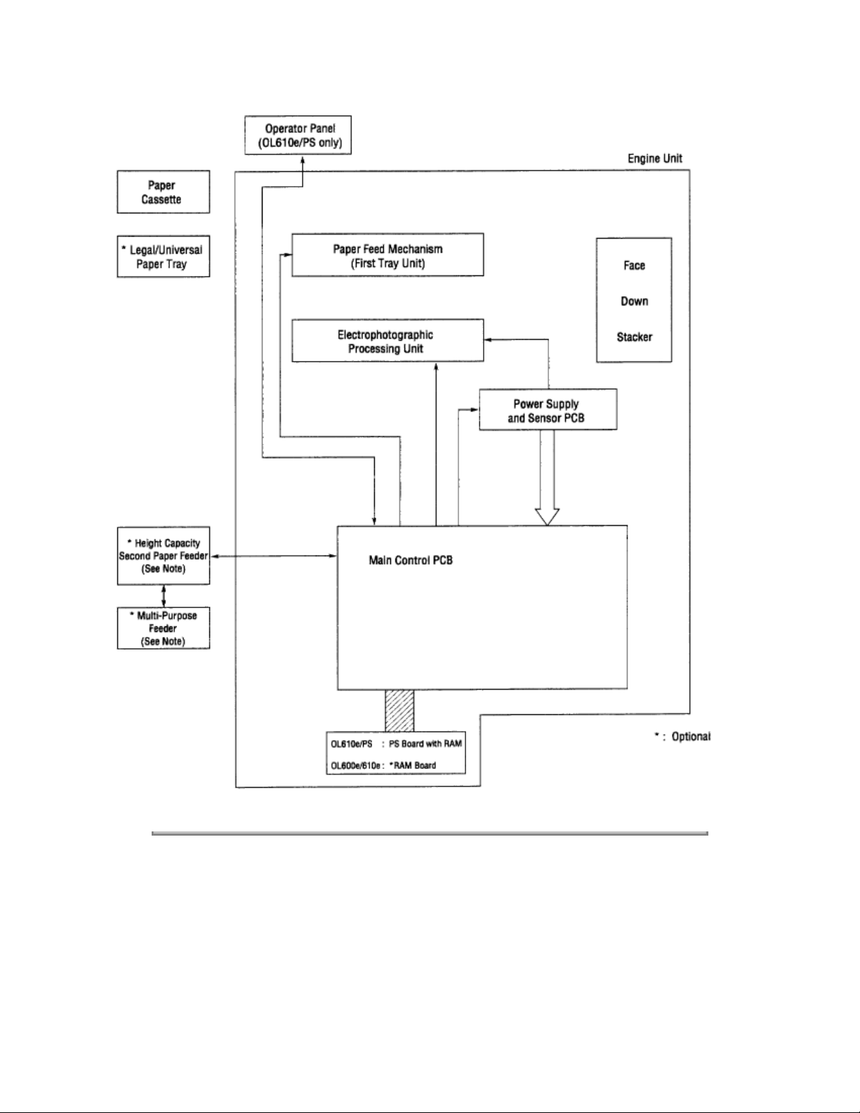
Figure 1-1
Copyright 1997, Okidata, Division of OKI America, Inc. All rights reserved. See the OKIDATA Business
Partner Exchange (BPX) for any updates to this material. (http://bpx.okidata.com)
Page 11

Service Guide OL600e/610e/610ePS
Chapter 1 Configuration
1.2 Printer Configuration
The printer unit consists of the following hardware components:
• Electrophotographic Processor
• Paper Feeder
• Main Control PCB
• Operator Panel (OL610e/PS)
• Power Supply Unit
• PS Board (OL610e/PS)
The printer unit configuration is shown in Figure 1-2.
Page: 5
Page 12
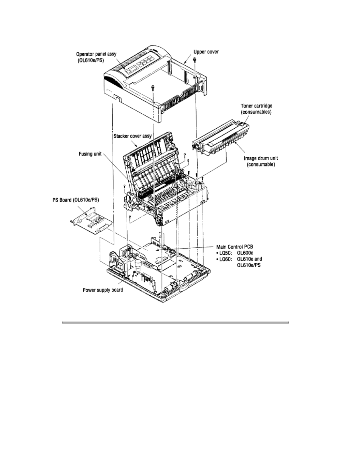
Figure 1-2
Copyright 1997, Okidata, Division of OKI America, Inc. All rights reserved. See the OKIDATA Business
Partner Exchange (BPX) for any updates to this material. (http://bpx.okidata.com)
Page 13
Service Guide OL600e/610e/610ePS
Chapter 1 Configuration
1.3 Optional Configuration
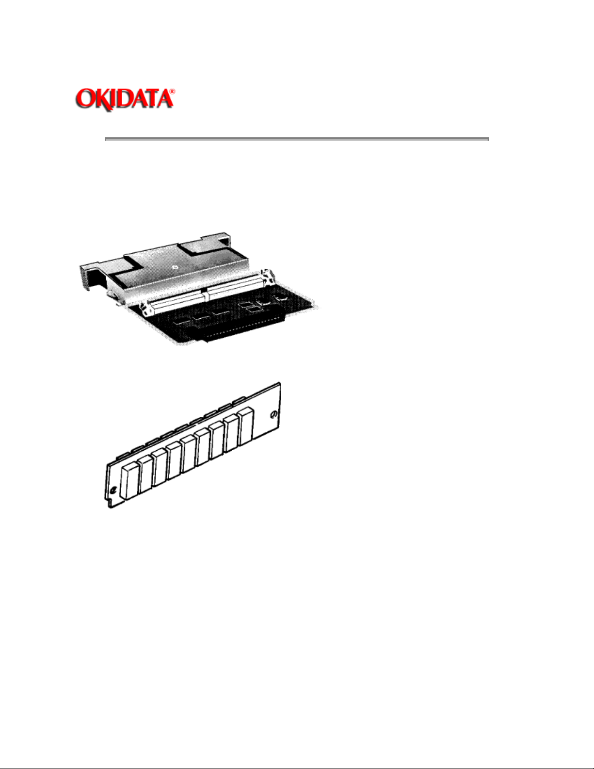
The options shown below are available for use with OL600e, OL610e and OL610e/PS. These are
available separately from the printer unit.
(1) 1MB Memory Expansion Board (OL600e/610e)
Page: 6
(2) SIMM (Single In-line Memory Module)
(3) Legal/Universal Paper Cassette
Page 14
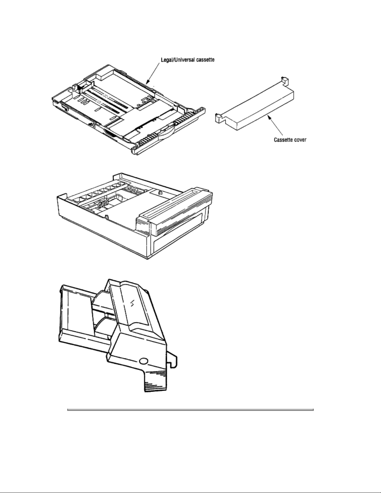
(4) High Capacity Second Paper Feeder
(5) Multi-Purpose Feeder
Copyright 1997, Okidata, Division of OKI America, Inc. All rights reserved. See the OKIDATA Business
Partner Exchange (BPX) for any updates to this material. (http://bpx.okidata.com)
Page 15

Service Guide OL600e/610e/610ePS
Chapter 1 Configuration
1.4 Specification
(1) Type Desktop
(2) External dimensions Height 6.3" (160 mm) Width 12.6" (320 mm) Depth 14.17" (360 mm)
(3) Weight 8 kg
(4) Developing method Dry electrophotography Exposing method LED stationary head
(5) Paper used
Type
- Standard paper e.g. Xerox 4200 (20 lbs)
- Application paper (manual face-up feed)
- Label Envelope OHP paper (Transparency)
Page: 7
Size
- Standard sizes Letter (ODA)
Legal (option)
Executive
Envelope A4 A5 B5 A6
Applicable sizes Width: 3.94" to 8.5" (100 to 216 mm) Length: 5.83" to 14" (148 to 355.6 mm)
Thickness
Automatic feed: 16 to 24 lbs (60 to 90 g/m 2 )
Manual feed: Label, OHP paper (transparency)
Envelope
(6) Printing speed
First print: 25 sec.
Continuous print: 6 pages/min. for letter size paper
Warm-up time: 60 sec. [at room temperature 77°F (25°C) and rated voltage (120 VAC)]
(7) Paper feeding method Automatic feed or manual feed
(8) Paper delivery method Face down/face up
(9) Resolution OL600e: 300 x 300 dots/inch OL600e (Hiper-W driver), OL610e, OL610e/PS: 600 x 600
dots/inch
(10) Power input 120 VAC +5.5%, 15% (ODA) 230 VAC +15%, 15% (ODA)
(11) Power consumption Peak: Approx. 420W Typical operation: Approx. 160W Idle: Approx. 55W Power
save mode: Approx. 15W
Page 16

(12) Temperature and humidity During operation: 50 to 90°F (10 to 32°C) In storage: 14 to 110°F (10 to
43°C)
(13) Noise During operation: 48 dB (A) or less Standby: 38 dB (A) or less
(14) Consumables Toner cartridge kit 2,000 (5% duty) Image drum cartridge 20,000 (at continuous
printing) 15,000 (3 pages/job) 10,000 (1 page/job)
Copyright 1997, Okidata, Division of OKI America, Inc. All rights reserved. See the OKIDATA Business
Partner Exchange (BPX) for any updates to this material. (http://bpx.okidata.com)
Page 17
Service Guide OL600e/610e/610ePS
Chapter 1 Configuration
1.5 Safety Standards
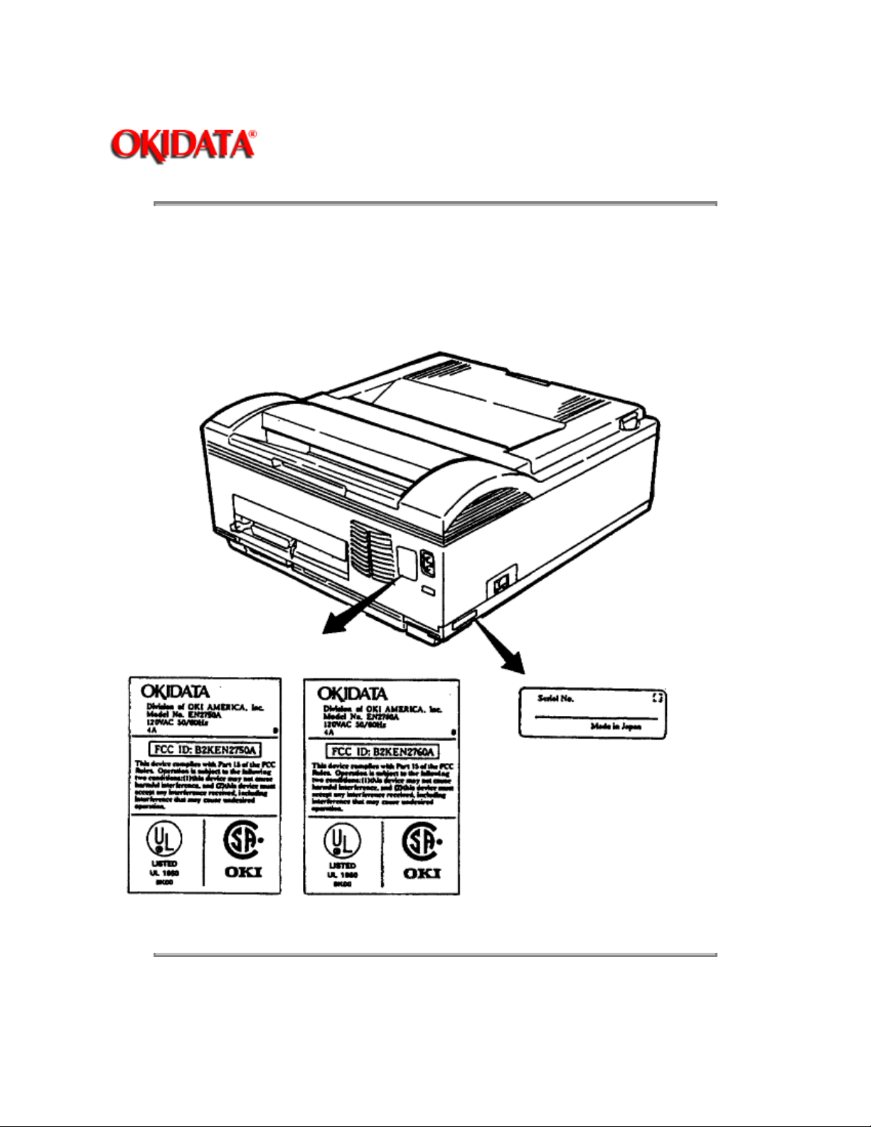
1.5.1 Certification Label
The safety certification label is affixed to the printer at the location shown below.
Page: 8
Copyright 1997, Okidata, Division of OKI America, Inc. All rights reserved. See the OKIDATA Business
Partner Exchange (BPX) for any updates to this material. (http://bpx.okidata.com)
Page 18
Service Guide OL600e/610e/610ePS
Chapter 1 Configuration
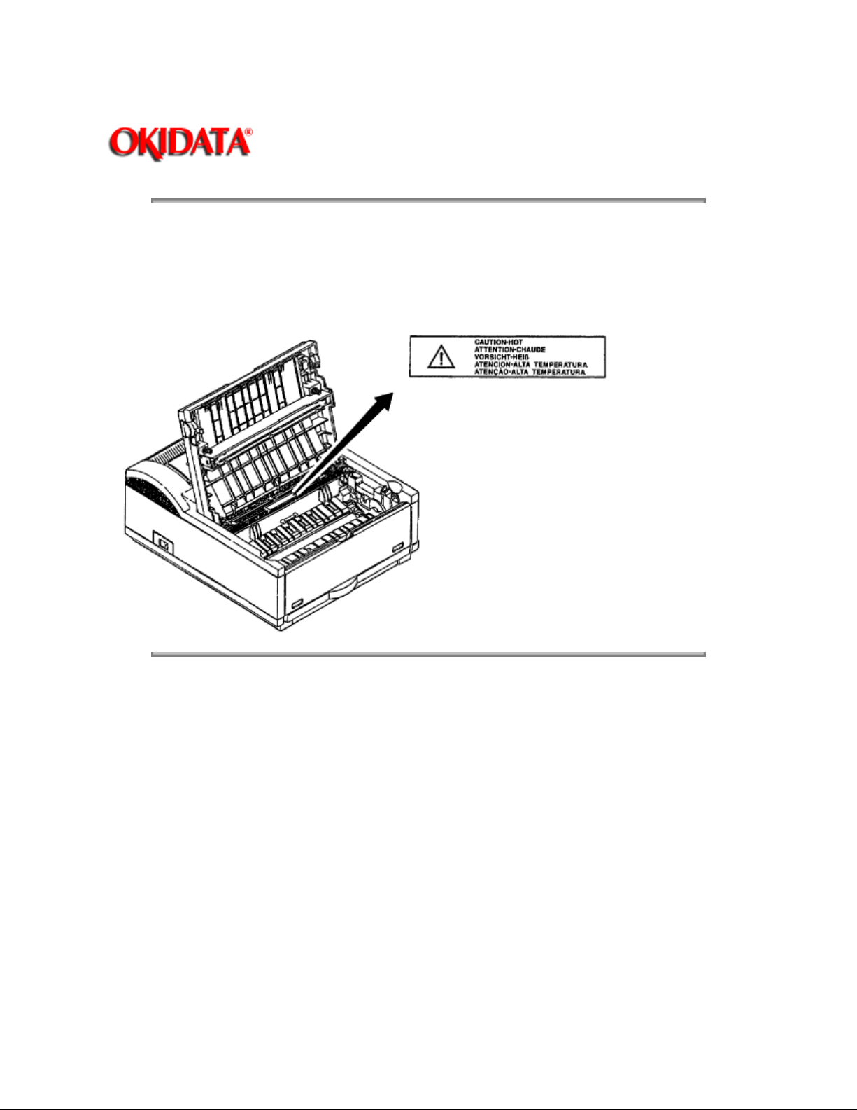
1.5.2 Warning Labels
The warning labels are affixed to the sections that may cause bodily injury.
Follow the instructions on warning labels during maintenance.
Page: 9
Copyright 1997, Okidata, Division of OKI America, Inc. All rights reserved. See the OKIDATA Business
Partner Exchange (BPX) for any updates to this material. (http://bpx.okidata.com)
Page 19
Service Guide OL600e/610e/610ePS
Chapter 1 Configuration
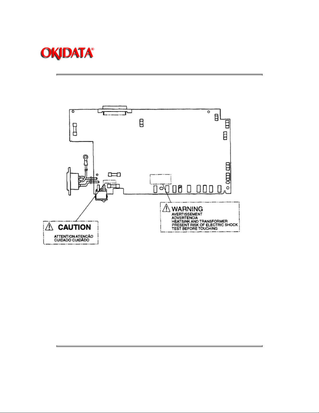
1.5.3 Warning/Caution Markings
The following warning and caution markings appear on the power supply board.
Page: 10
ENGLISH Heatsink and transformer core present risk of electric shock. Test before touching.
FRENCH Le dissipateur thermique et le noyau du transformateur présentent des risques de choc
électrique. Testez avant de, manipuler. SPANISH Las disipadores de color el núcel del transformador
pueden producir un choque eléctrico. Compruebe antes de tocar. PORTUGUESE O dissipador de calor e
o núcleo do fransiormador apresentam risco de choque elétrico. Teste antes de focar.
ENGLISH Circuits may be live after fuses open.
FRENCH Il se peut que les circuits soient sous tension une fois que les fusibles ont été rerirés.
SPANISH Las circuitos pueden estar activos una vez que se hayan abierio los fusibles.
PORTUGUESE Os circuitos podem estar energizados após os fusiveis se queimarem.
Copyright 1997, Okidata, Division of OKI America, Inc. All rights reserved. See the OKIDATA Business
Partner Exchange (BPX) for any updates to this material. (http://bpx.okidata.com)
Page 20

Page: 11
Service Guide OL600e/610e/610ePS
Chapter 2 Operation Description
2. OPERATION DESCRIPTION
The OL600e, OL610e and OL610e/PS consist of a Main Control PCB, a PostScript board (OL610e/PS), a
power supply/sensor board, an operator panel (OL610e/PS), and an electrophotographic process
mechanism.
The control board and the PostScript board receive data via the host I/F; these then decode, edit and
store the data in memory. After a single page of data is completely edited, they reference the font memory
and generate bit image data, which is transferred to the LED head in one-dot line units.
The data is printed on the paper by means of the electrophotographic process mechanism.
The OL600e and OL610e use proprietary software to control printer operations and status monitoring. The
OL610e/PS has an operator panel to perform these functions.
Figure 2-1 shows the OL600e block diagram.
Figure 2-2 shows the OL610e block diagram.
Figure 2-3 shows the OL610e/PS block diagram.
Page 21
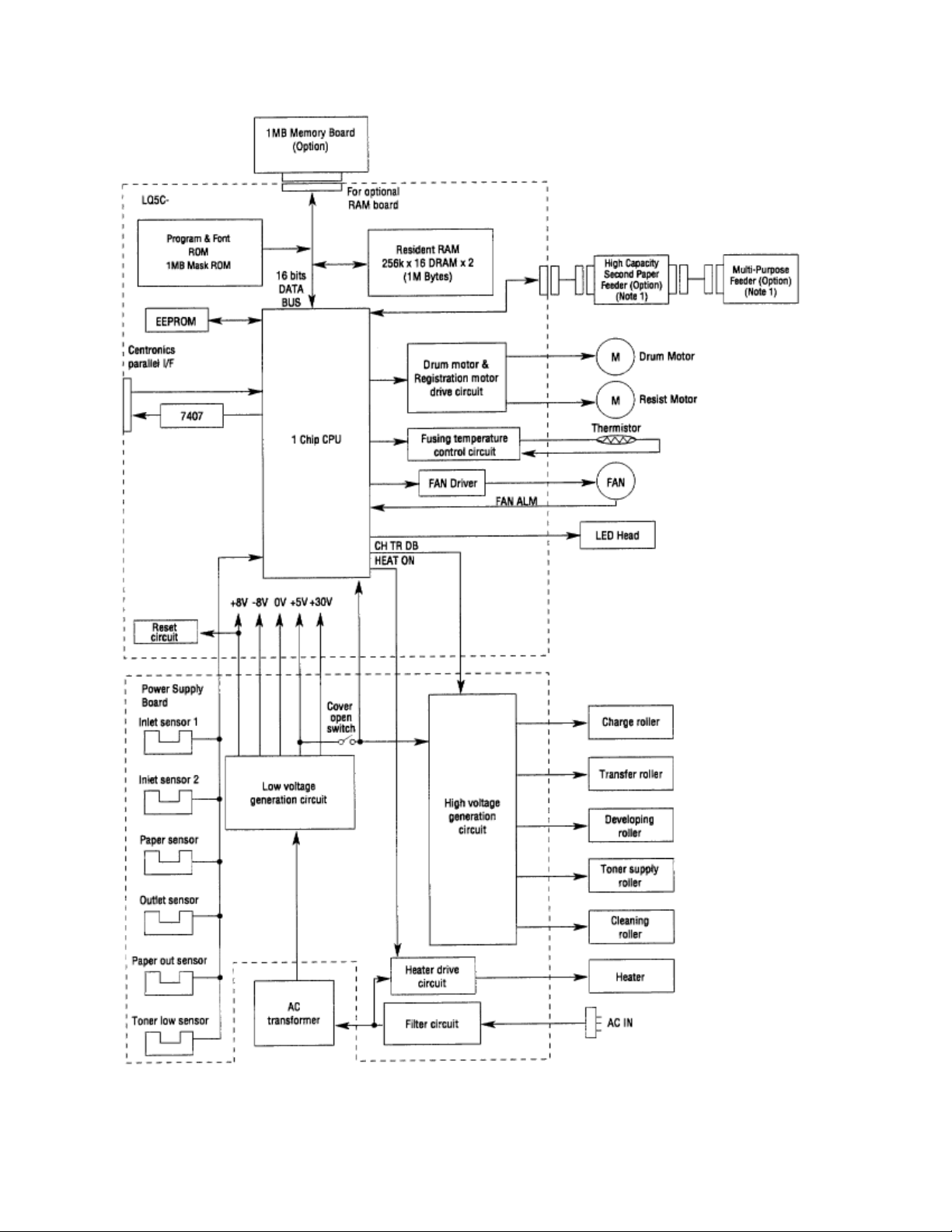
Figure 2-1 OL600e Block Diagram
Page 22

Copyright 1997, Okidata, Division of OKI America, Inc. All rights reserved. See the OKIDATA Business
Partner Exchange (BPX) for any updates to this material. (http://bpx.okidata.com)
Page 23

Page: 12
Service Guide OL600e/610e/610ePS
Chapter 2 Operation Description
Page 24
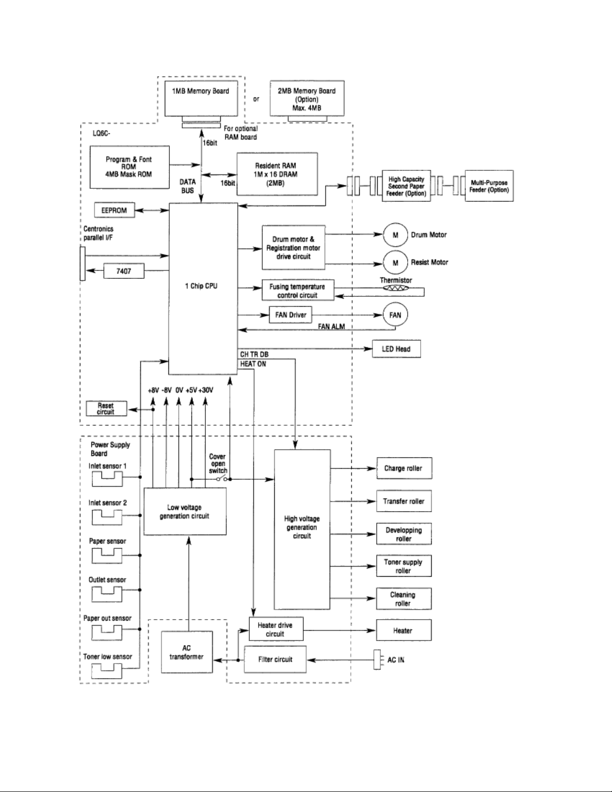
Figure 2-2 OL610e Block Diagram
Page 25

Copyright 1997, Okidata, Division of OKI America, Inc. All rights reserved. See the OKIDATA Business
Partner Exchange (BPX) for any updates to this material. (http://bpx.okidata.com)
Page 26

Page: 13
Service Guide OL600e/610e/610ePS
Chapter 2 Operation Description
Page 27
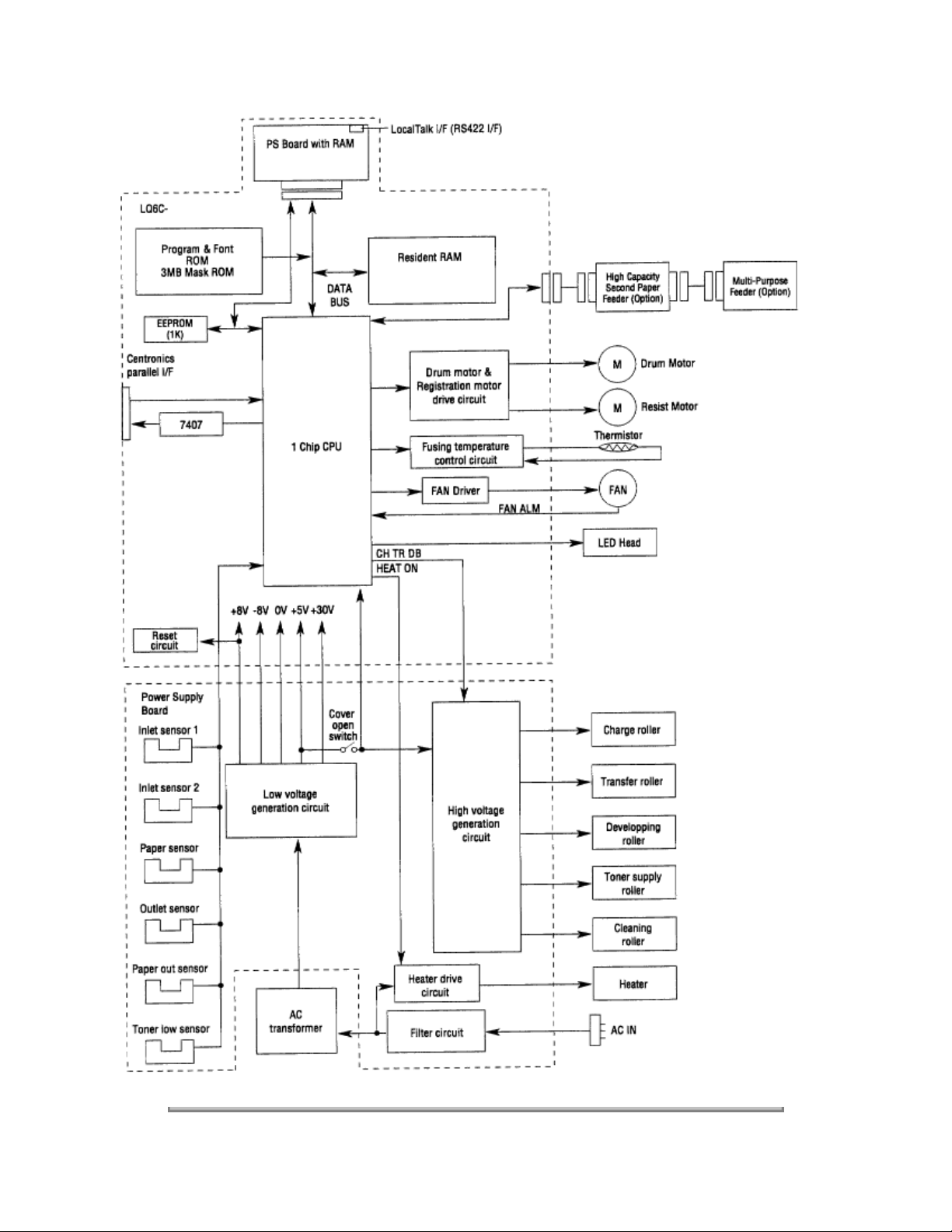
Figure 2-3 OL610e/PS Block Diagram
Page 28

Copyright 1997, Okidata, Division of OKI America, Inc. All rights reserved. See the OKIDATA Business
Partner Exchange (BPX) for any updates to this material. (http://bpx.okidata.com)
Page 29

Page: 14
Service Guide OL600e/610e/610ePS
Chapter 2 Operation Description
2.1 Control Board
The control board consists of a single chip CPU, Program & Font ROMsone DRAM for the OL600e, two
DRAMs for the OL610e an EEPROM, a host interface circuit, and a mechanism driving circuit.
(1) Single chip CPU
The single chip CPU is a custom CPU (32-bit internal bus, 16-bit external bus, 25.54 MHz clock with input
frequency from a 12.27 MHz clock) which incorporates the MIPS 3000 RISC CPU and its peripheral
devices, and has the following functions:
Built-in device
Chip select controller
Bus controller
DRAM controller
DMA controller Transfer of image data from DRAM to video
Parallel interface controller Control of Centronics parallel interface
Serial interface controller Control of RS-232C serial interface
Video output port
LED STB output port
Timer Generation of various control timing signals
Serial I/O port Control of operator panel EEPROM and options
I/O port Input and output of sensor and motor signals
(2) Program & Font ROM
OL600e/610e
Function
Control of ROM DRAM and I/O device
output port
Control of LED head
Monitoring of paper running and paper size
The Program & Font ROM stores the equipment program and various types of fonts. EPROM or Mask
ROM is used for a Program & Font ROM. The mounting location of this Program & Font ROM varies
depending on the type of ROM (for the mounting location see 7.2).
OL610e/PS
The Program ROM & Font ROM store the HP4 emulation program and various types of fonts. Mask ROM
is used for a Program & Font ROM.
Page 30

(3) DRAM
OL600e/610e
The DRAM is a resident memory 1MB in the OL600e, 2MB in the OL610e used as a buffer; it stores
edited data, image data, DLL data, and macro data.
OL610e/PS
The DRAM is resident memory (2MB on the board plus 0.5MB on the PS board) used as a buffer; it stores
edited data, image data, DLL data, and macro data. In PostScript mode, it is used as VM and font cache
also.
(4) EEPROM
1,024-bit Electrically Erasable PROM (EEPROM), is loaded with the following data:
- Menu data
- Various counter data (Page counter, Drum counter)
- Adjusting parameters (LED head drive time, print start position, paper feed length)
(5) Parallel Interface
Parallel data is received from the host system via parallel interface which conforms to the Centronics
specification. IEEE 1284 specification bi-directional parallel is supported.
Copyright 1997, Okidata, Division of OKI America, Inc. All rights reserved. See the OKIDATA Business
Partner Exchange (BPX) for any updates to this material. (http://bpx.okidata.com)
Page 31
Page: 15
Service Guide OL600e/610e/610ePS
Chapter 2 Operation Description
2.2 PS Board (OL610e/PS)
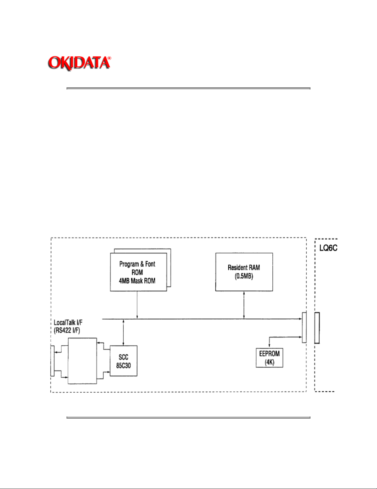
The PS board consists of two Program & Font ROM's, DRAM's, an EEPROM, and a host interface circuit.
(1) Program & Font ROM's
The Program & Font ROMs store the PostScript Level II program and its fonts. Mask ROM is used for the
Program & Font ROMs.
(2) DRAM
0.5MB of DRAM's reside on the PS board.
(3) EEPROM
4,096 bit-Electrically Erasable PROM (EEPROM) is mounted on the PS board for storing the PostScript's
menu settings.
(4) LocalTalk I/F
AppleTalk protocol data is received from the host system via LocalTalk interface. The block diagram is
shown in Figure 2-4.
Figure 2-4 PS Board Block Diagram
Copyright 1997, Okidata, Division of OKI America, Inc. All rights reserved. See the OKIDATA Business
Partner Exchange (BPX) for any updates to this material. (http://bpx.okidata.com)
Page 32
Page: 16
Service Guide OL600e/610e/610ePS
Chapter 2 Operation Description
2.3 Power Supply Board
The power supply board consists of an AC filter circuit, a low voltage power supply circuit, a high voltage
power supply circuit, heater drive circuit, and photosensors.
(1) Low Voltage Power Supply Circuit
This circuit generates the following voltages.
Output voltage
+5 V Logic circuit supply voltage
+30 V Motor and fan drive voltage and source
+8 V Analog supply voltage
-8 V PS board and analog circuit supply voltage
(2) High Voltage Power Supply Circuit
This circuit generates following voltages required for electrophotographic process from +5 V, according to
the control sequence from the control board. When cover open state is detected, +5 V supply is
interrupted automatically to stop the supply of all high-voltage outputs.
Output
CH -1.35 KV Voltage applied to charging
DB -300 V/+300 V Voltage applied to developing
Voltage Use Remarks
Use
voltage for high-voltage supply
roller
roller
SB -450 V/ 0 V Voltage applied to toner supply
roller
TR +500 V to +4 KV/-750 V Voltage applied to transfer
roller
CB +400 V Voltage applied to cleaning
roller
(3) Photosensor
The photosensor mounted on this power supply board monitors the paper running state during printing.
Variable
Page 33
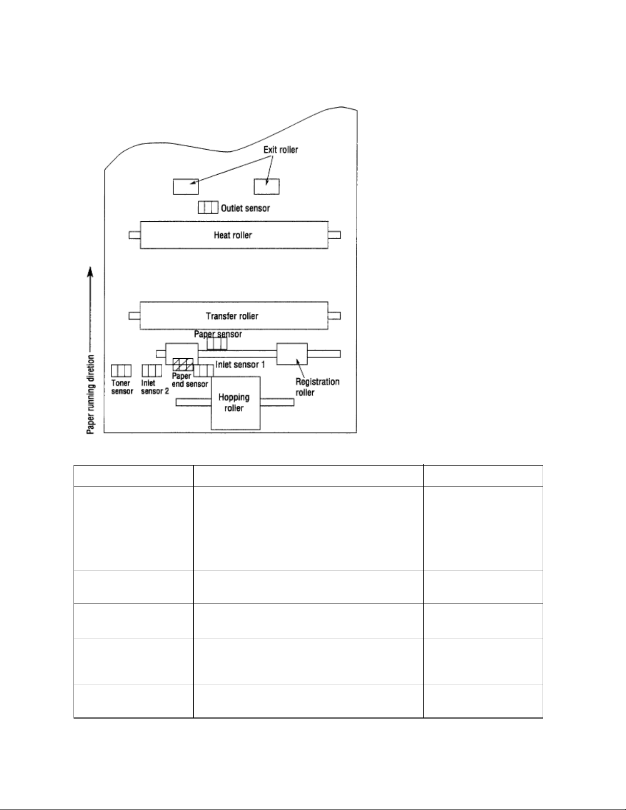
The sensor layout diagram is shown in Figure 2-3.
Figure 2.5
Sensor
Inlet sensor 1 Detects the leading edge of the paper and gives
Intel sensor 2 Detects the form width. ON: A4 or larger
Paper sensor Detects the leading portion of the paper.
Outlet sensor Monitors the paper feeding and size according
Paper end sensor Detects the end of the paper. ON: Paper exists.
Function Sensing state
ON: Paper exists.
the supervision timing for switching from
hopping operation to feeding operation.
Monitors paper feeding situation and paper size
based on the paper arrival time and running
time.
Monitors the paper feeding situation.
to the time of arrival to and leaving past the
sensor.
OFF: No paper exists.
OFF: Smaller than A4
ON: Paper exists.
OFF: No paper exists.
ON: Paper exists.
OFF: No paper exists.
OFF: No paper exists.
Page 34

Toner low sensor Detects the lack of toner. - - - - -
Copyright 1997, Okidata, Division of OKI America, Inc. All rights reserved. See the OKIDATA Business
Partner Exchange (BPX) for any updates to this material. (http://bpx.okidata.com)
Page 35
Page: 17
Service Guide OL600e/610e/610ePS
Chapter 2 Operation Description
2.4 Electrophotographic Process
2.4.1 Electrophotographic Process Mechanism
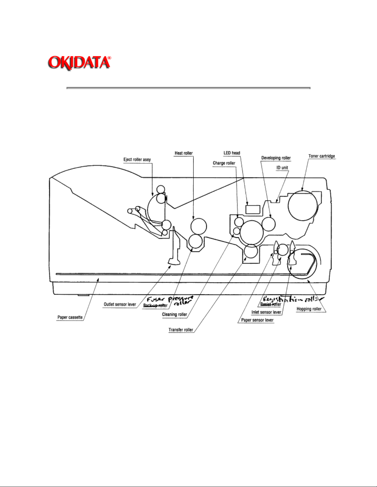
This mechanism uses the electrophotographic process to print image data supplied by the control board.
The layout of the electrophotographic process mechanism is shown in Figure 2-6.
Figure 2-6
(1) Image Drum Unit
The image drum unit consists of a light-sensitive drum, a charger, and a developer. The unit forms a toner
image on the sensitive drum, using an electrostatic latent image formed by the LED head.
(2) Registration Motor
The registration motor is a pulse motor of 48 steps/rotation, which is two-phase excited by the signal from
the Main Control PCB. It drives the hopping and registration rollers via two one-way clutches according to
the direction of rotation.
(3) Drum Motor
Page 36

The drum motor is a pulse motor of 48 steps/rotation, which is two-phase excited by the signal from the
Main Control PCB and is the main motor of this mechanism.
(4) LED Head
Image data for each dot line from the control board is received by the shift register and latch register. The
2560/2496 LEDs are driven to radiate the image data on the image drum.
(5) Fuser
The fuser consists of a heater, a heat roller, a thermistor and a thermostat.
The AC voltage from the power supply board is applied to the heater controlled by the HEATON signal
from the control board. This AC voltage heats the heater. The Main Control PCB monitors the heat roller
temperature via the thermistor, and regulates the heater roller to a predetermined temperature (165°C) by
connecting or disconnecting the AC voltage supply to the heater.
When the temperature of the heater roller rises abnormally, the thermostat of the heater voltage supply
circuit becomes active and cuts the AC voltage supply.
Copyright 1997, Okidata, Division of OKI America, Inc. All rights reserved. See the OKIDATA Business
Partner Exchange (BPX) for any updates to this material. (http://bpx.okidata.com)
Page 37

Page: 18
Service Guide OL600e/610e/610ePS
Chapter 2 Operation Description
2.4.2 Electrophotographic Process
The electrophotographic processing is outlined below. Figure 2-7 shows the electrophotographic printing
process.
1
Charging
The surface of the image drum is given a uniform negative charge by applying the negative voltage to the
charge roller.
2
Exposure
Light emitted from the LED head irradiates the negatively charged surface of the image drum. The surface
potential of the irradiated portion becomes lower, forming the electrostatic latent image associated with the
print image.
3
Developing and toner recovery
When the negatively charged toner is brought into contact with the image drum, it is attracted to the
electrostatic latent image by static electricity, making the image visible.
At the same time, the residual toner on the image drum is attracted to the developing roller by static
electricity.
4
Transfer
When paper is placed over the image drum surface, the positive charge which is opposite in polarity to
that of the toner, is applied to the reverse side by the transfer roller. The toner is attracted by the positive
charge and is transferred onto the paper. This transfers the toner image formed on the image drum onto
the paper.
5
Temporary cleaning
Residual toner, which remains on the image drum without being transferred, is evened out by the cleaning
roller and is attracted to the cleaning roller by static electricity.
6
Fusing
The transferred toner image is fused to the paper by heat and pressure.
Figure 2-8 shows an electrophotographic process timing chart.
Page 38
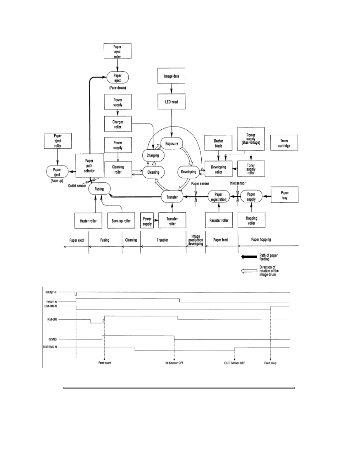
Figure 2-7
Figure 2-8
Copyright 1997, Okidata, Division of OKI America, Inc. All rights reserved. See the OKIDATA Business
Partner Exchange (BPX) for any updates to this material. (http://bpx.okidata.com)
Page 39
Page: 19
Service Guide OL600e/610e/610ePS
Chapter 2 Operation Description
2.4.3 Process Operation Descriptions
(1) Hopping and Feeding
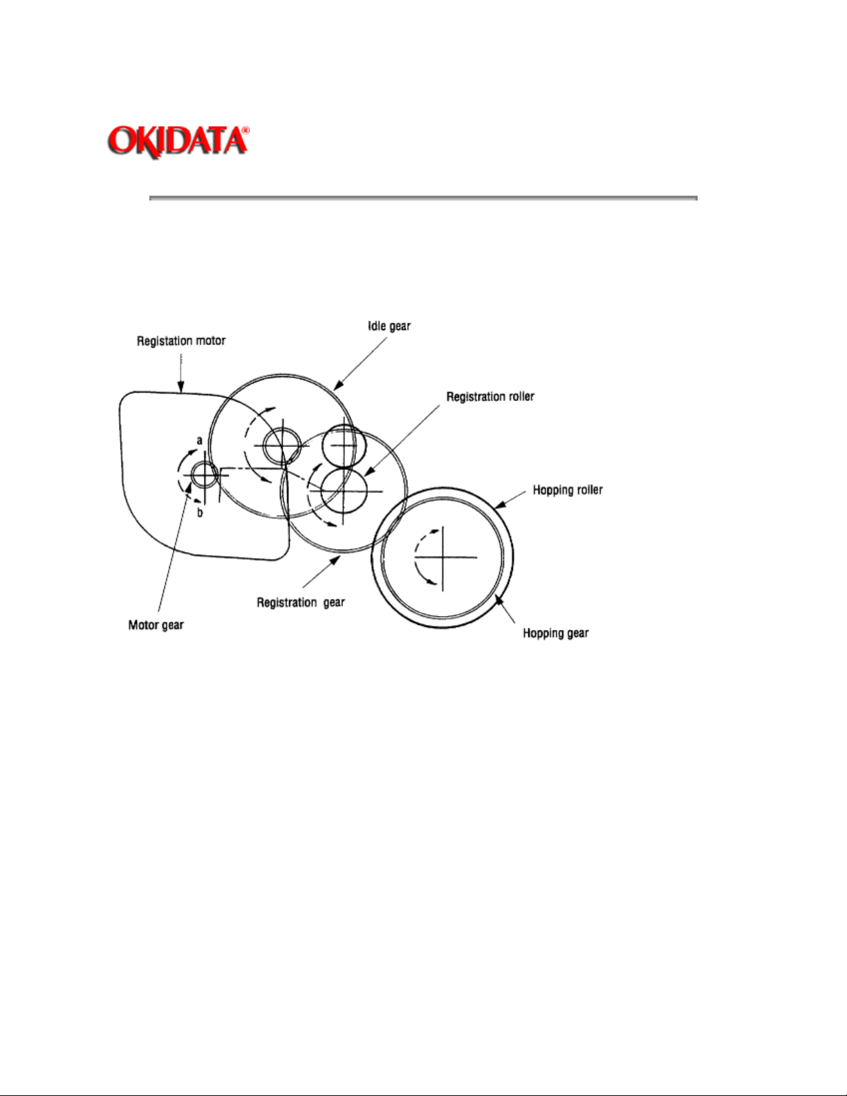
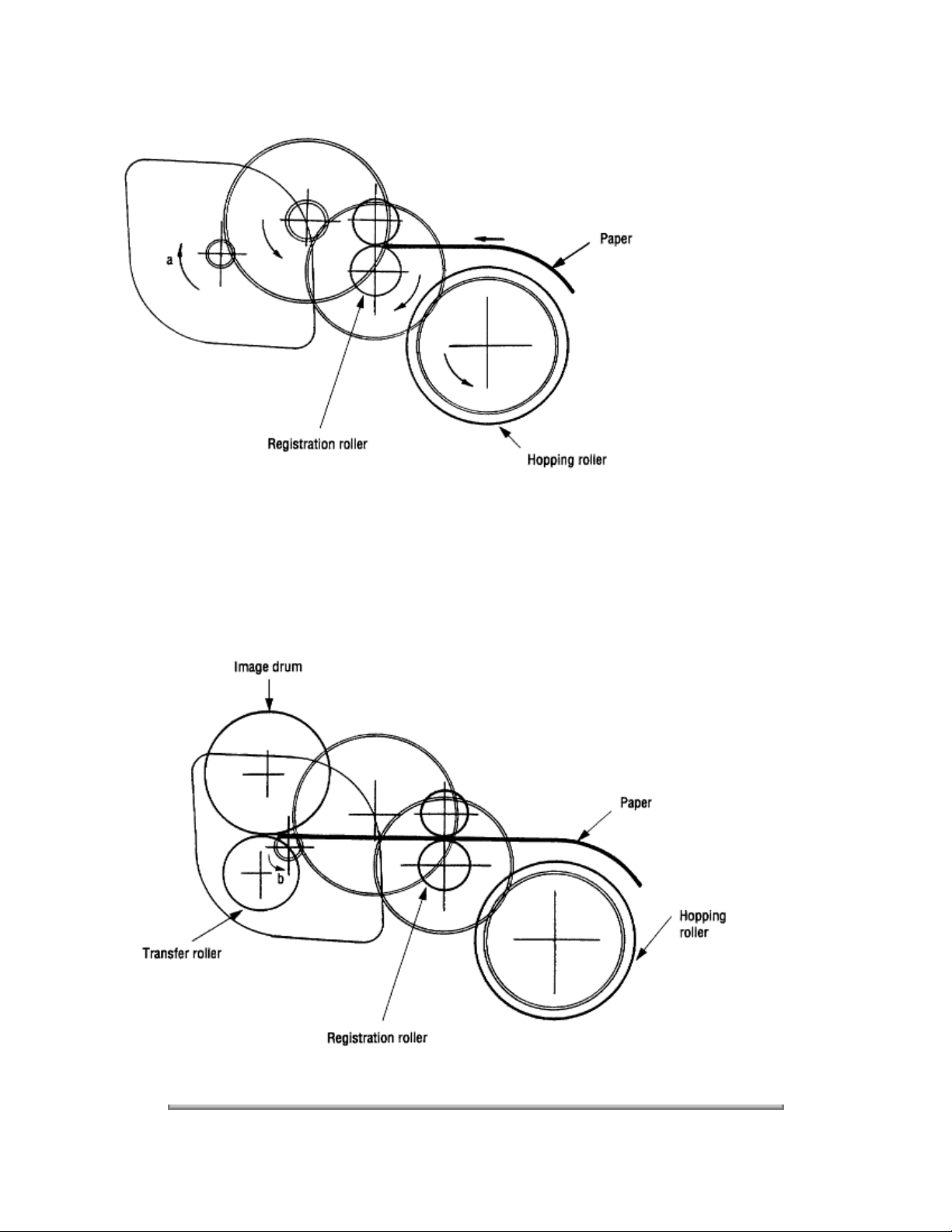
Hopping and feeding motions are actuated by a single registration motor in the mechanism as shown
below:
The registration motor turning in direction "a" drives the hopping roller. The registration motor turning in
direction "b" drives the registration roller. The registration and hopping gears have one-way bearings, so
turning any of these gears in the reverse direction will not transmit the motion to the corresponding roller.
(a) Hopping
1
For hopping, the registration motor turns in direction "a" (CW direction) and drives the hopping roller to
advance the paper until the inlet sensor turns on (in this case, the registration gear also turns, but the
registration roller is prevented from turning by the one-way bearings).
2
After inlet sensor is turned on by the paper advance, the paper is further advanced to a predetermined
distance until the paper hits the registration roller (the skew of the paper can thus be corrected).
Page 40
(b) Feeding
1 When hopping is completed, the registration motor turning in direction "b" (CCW direction) drives the
registration roller to advance the paper (in this case, the hopping gear also turns, but the hopping roller is
prevented from turning by the one-way bearings).
2 The paper is further advanced in synchronization with the print data.
Page 41

Copyright 1997, Okidata, Division of OKI America, Inc. All rights reserved. See the OKIDATA Business
Partner Exchange (BPX) for any updates to this material. (http://bpx.okidata.com)
Page 42
Page: 20
Service Guide OL600e/610e/610ePS
Chapter 2 Operation Description
(2) Charging
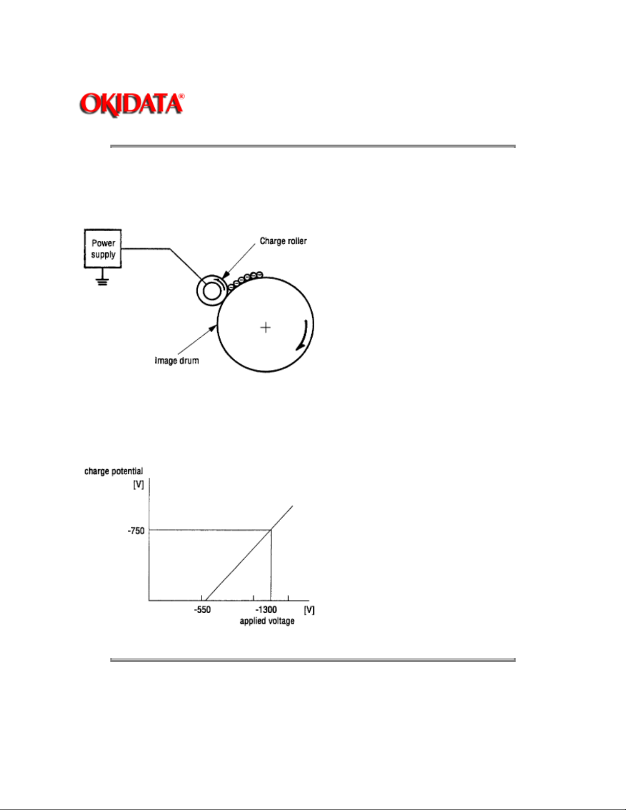
Charging is actuated by the application of the DC voltage to the charge roller that is in contact with the
image drum surface.
The charge roller consists of two layers: a conductive layer and a surface protective layer, both having
elasticity to secure good contact with the image drum. When the DC voltage applied by the power supply
exceeds the threshold value, charging begins. The applied voltage is proportional to the charge potential,
with an offset of approximately 550V.
Copyright 1997, Okidata, Division of OKI America, Inc. All rights reserved. See the OKIDATA Business
Partner Exchange (BPX) for any updates to this material. (http://bpx.okidata.com)
Page 43
Page: 21
Service Guide OL600e/610e/610ePS
Chapter 2 Operation Description
(3) Exposure
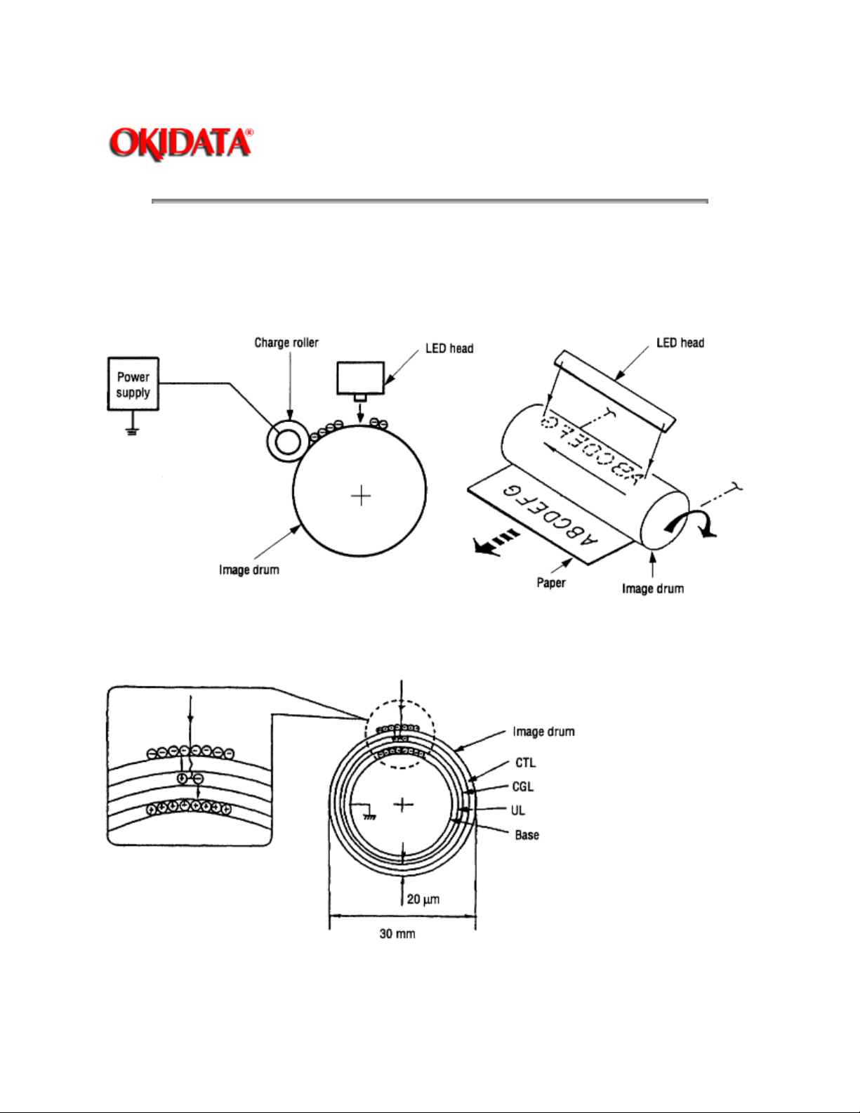
Light emitted by the LED head irradiates the image drum surface with a negative charge. The surface
potential of the irradiated portion drops, forming an electrostatic latent image associated with the image
signal.
The image drum is coated with an underlayer (UL), a carrier generation layer (CGL), and carrier transfer
layer (CTL) on aluminum base. The organic photo-conductor layer (OPC), comprising CTL and CGL, is
about 20 µm thick.
The image roller surface is charged to about 750 V by the contact charge of the charge roller.
Page 44
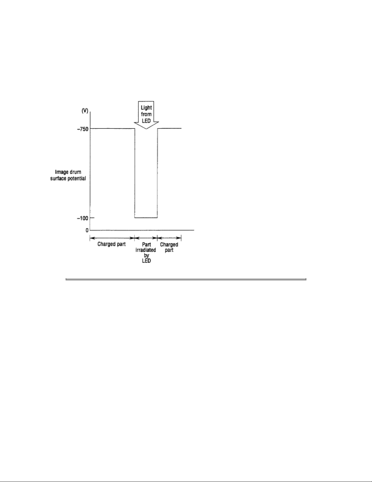
When the light from the LED head irradiates the image drum surface, the light energy generates positive
and negative carriers in the CGL. The positive carriers are moved to the CTL by an electrical field acting
on the image drum. Likewise, the negative carriers flow into the aluminum layer (ground).
The positive carriers moved to the CTL combine with the negative charges on the image drum surface
accumulated by the contact charge of the charge roller, lowering the potential on the image drum surface.
The resultant drop in the potential of the irradiated portion of the image drum surface forms an
electrostatic latent image on it. The irradiated portion of the image drum surface is kept to about 100 V.
Copyright 1997, Okidata, Division of OKI America, Inc. All rights reserved. See the OKIDATA Business
Partner Exchange (BPX) for any updates to this material. (http://bpx.okidata.com)
Page 45
Page: 22
Service Guide OL600e/610e/610ePS
Chapter 2 Operation Description
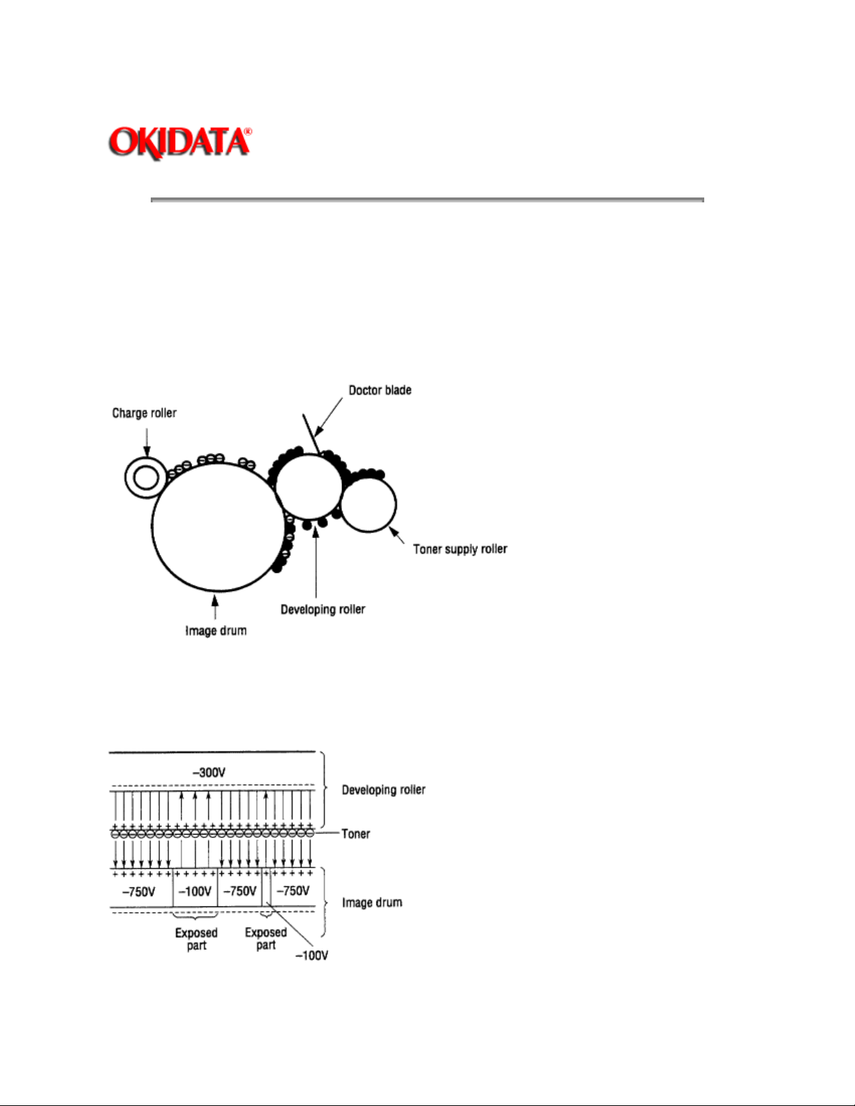
(4) Developing
Toner is attracted to the electrostatic latent image on the image drum surface, converting it into a visible
toner image. Developing takes place through the contact between the image drum and the developing
roller.
1
As the toner supply roller rotates while rubbing on the developing roller, a friction charge is generated
between the developing roller and the toner, allowing the toner to be attracted to the developing roller (the
developing roller surface is charged positive and the toner is charged negative).
2
The toner attracted to the developing roller is scraped off by the doctor blade, forming a thin coat of
toner on the developing roller surface.
3
Toner is attracted to the exposed portion (low-potential part) of the image drum at the contact of the
image drum and the developing roller, making the electrostatic latent image visible.
Page 46
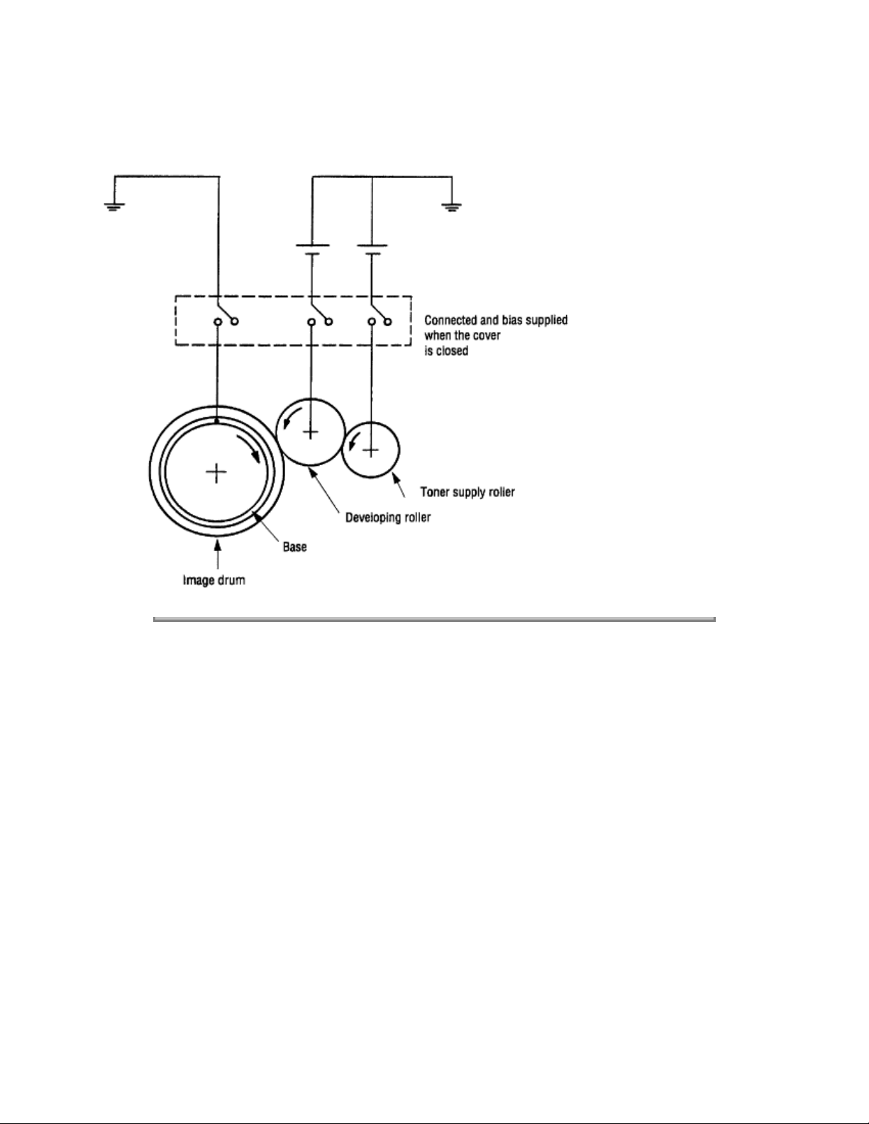
Note:
The bias voltage required during the developing process is supplied to the toner supply roller and
the developing roller, as shown in the diagram below. 450 VDC is supplied to the toner supply roller, 300
VDC to the developing roller.
Copyright 1997, Okidata, Division of OKI America, Inc. All rights reserved. See the OKIDATA Business
Partner Exchange (BPX) for any updates to this material. (http://bpx.okidata.com)
Page 47
Page: 23
Service Guide OL600e/610e/610ePS
Chapter 2 Operation Description
(5) Transfer
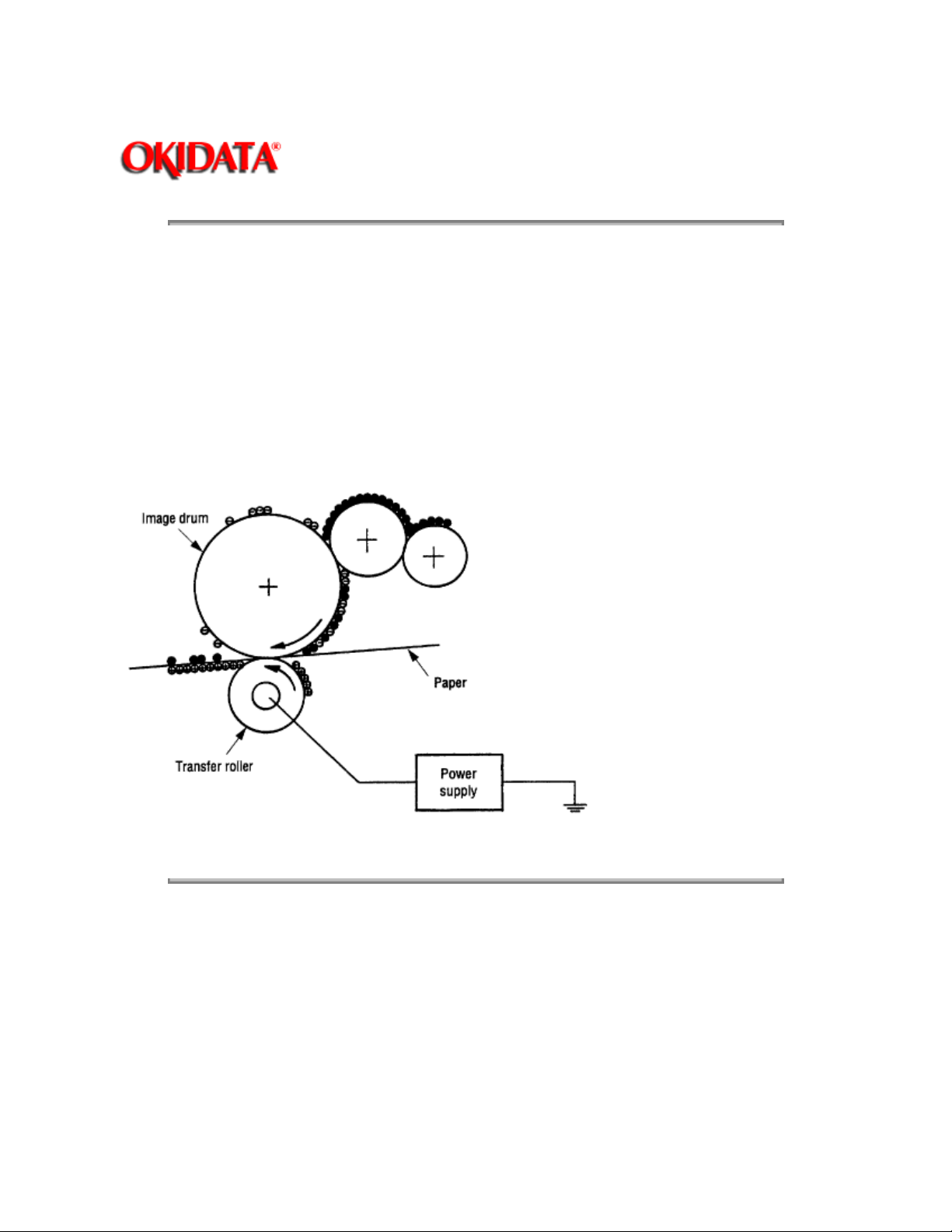
The transfer roller is composed of conductive sponge material, and is designed to get the image drum
surface and the paper in a close contact.
Paper is placed over the image drum surface, and the positive charge, opposite in polarity to that of the
toner, is applied to the paper from the reverse side.
The application of a high positive voltage from the power supply to the transfer roller causes the positive
charge inducement on the transfer roller surface, transferring the charge to the paper as it contacts the
transfer roller. The toner with negative charge is attracted to the image drum surface, and it is transferred
to the upper side of the paper due to the positive charge on the reverse side of the paper.
Copyright 1997, Okidata, Division of OKI America, Inc. All rights reserved. See the OKIDATA Business
Partner Exchange (BPX) for any updates to this material. (http://bpx.okidata.com)
Page 48
Page: 24
Service Guide OL600e/610e/610ePS
Chapter 2 Operation Description
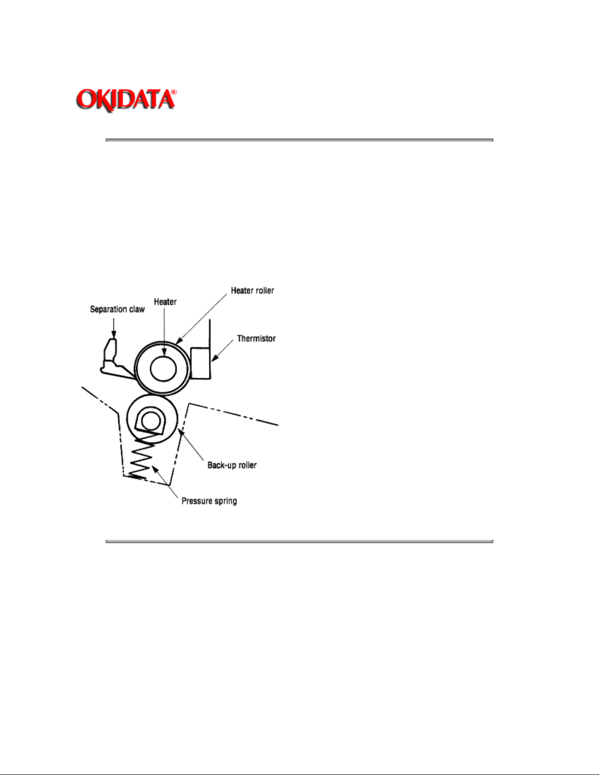
(6) Fusing
When the image transfer is completed, the toner image is fused to the paper by heat and pressure as the
paper with the toner image passes between the heater roller and the back-up roller. The heater roller with
Teflon coating incorporates a 400W heater (Halogen lamp), which heats the roller.
A thermistor, which is in contact with the heater roller, regulates the temperature of the heater roller at a
predetermined level (about 165°C). A safety thermostat cuts voltage supply to the heater off by opening
the thermostat in the event of abnormal temperature rises.
The back-up roller is held under a pressure of 3.8 kg applied by the pressure spring on each side.
Copyright 1997, Okidata, Division of OKI America, Inc. All rights reserved. See the OKIDATA Business
Partner Exchange (BPX) for any updates to this material. (http://bpx.okidata.com)
Page 49
Page: 25
Service Guide OL600e/610e/610ePS
Chapter 2 Operation Description
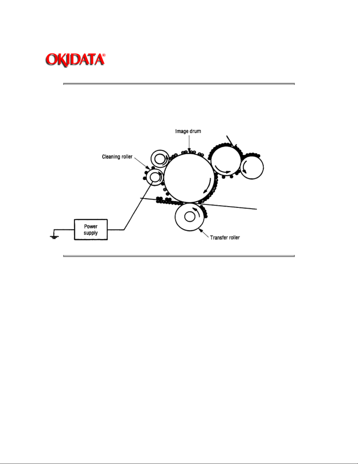
(7) Cleaning
When the transfer is completed, the residual toner left on the image drum is attracted to the cleaning roller
by static electricity, and the image drum surface is cleaned.
Copyright 1997, Okidata, Division of OKI America, Inc. All rights reserved. See the OKIDATA Business
Partner Exchange (BPX) for any updates to this material. (http://bpx.okidata.com)
Page 50

Page: 26
Service Guide OL600e/610e/610ePS
Chapter 2 Operation Description
(8) Cleaning of rollers
The charge, transfer and cleaning rollers are cleaned in the following cases:
• Warming up when the power is turned on.
• Warming up after the opening and closing of the cover.
• When the number of sheets accumulated reaches 10 or more, and the printout operation ends.
• Cleaning initiated by the user.
Changes in bias voltage applied to each roller moves the excess toner off the roller to the image drum and
returns it to the developer.
Copyright 1997, Okidata, Division of OKI America, Inc. All rights reserved. See the OKIDATA Business
Partner Exchange (BPX) for any updates to this material. (http://bpx.okidata.com)
Page 51

Page: 27
Service Guide OL600e/610e/610ePS
Chapter 2 Operation Description
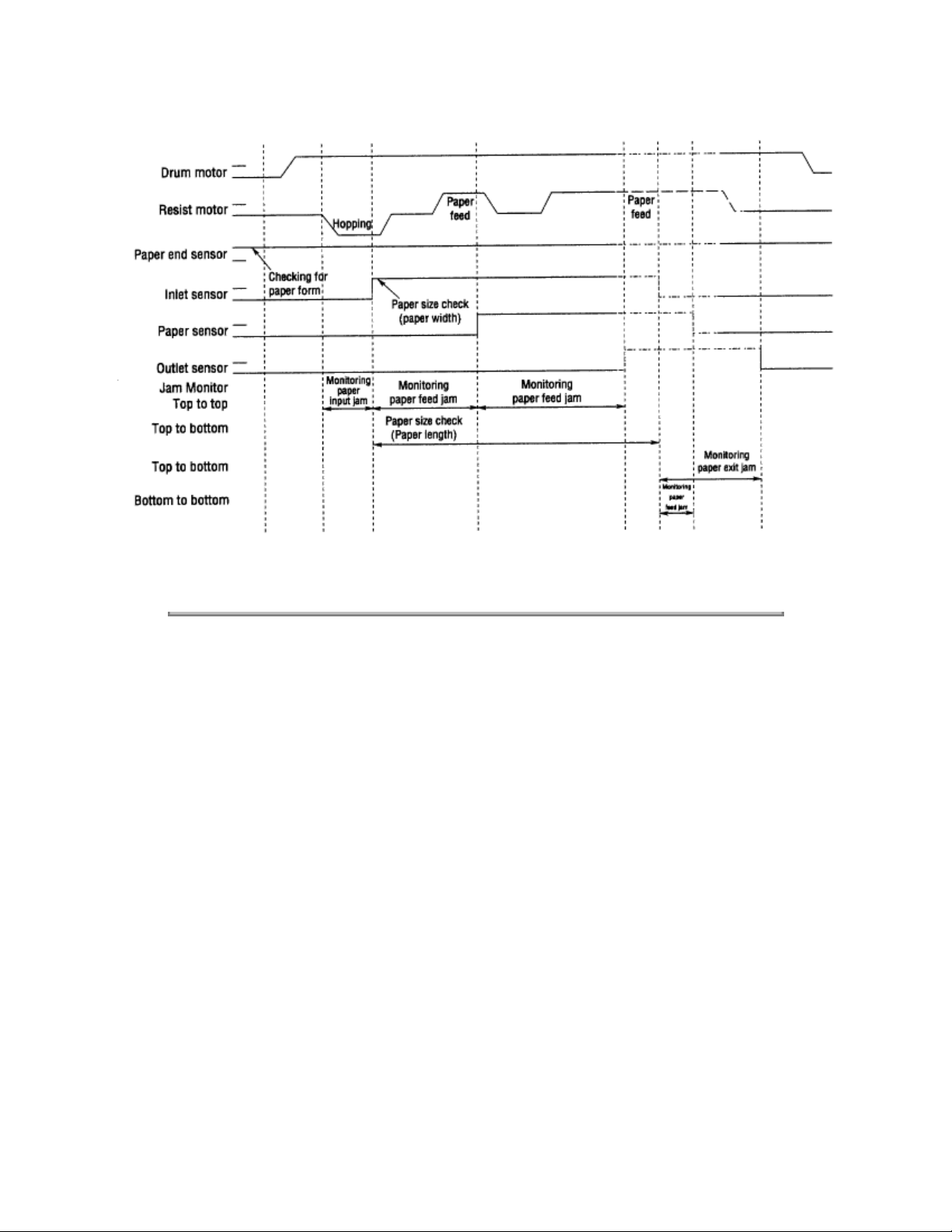
2.5 Paper Jam Detection
The paper jam detection function monitors the paper condition when the power is turned on and during
printing. When any of the following conditions arises, this function interrupts the printing process. If any of
the following errors is encountered, printing can be recovered by removing the jammed paper (by opening
the upper cover, removing the jammed paper and closing the upper cover).
Error
Paper input jam • The paper is in contact with the inlet sensor when the power is
Paper feed jam • The paper is in contact with at the paper sensor when the
Paper exit jam • The paper is in contact with the outlet sensor when the power
Cause of error
turned on.
• After hopping operation is attempted three times, the leading
edge of the paper does not reach the inlet sensor.
power is turned on.
• The leading edge of the paper does not reach the paper
sensor within a predetermined distance since the paper has
reached the inlet sensor.
• The trailing edge of the paper does not pass over the paper
sensor within a predetermined distance after the same has
passed over the inlet sensor.
• The leading edge of paper does not reach the outlet sensor
within a predetermined distance after the paper has reached the
paper sensor.
is turned on.
• The paper does not pass over the outlet sensor within a
predetermined distance after the leading edge of the paper has
reached the outlet sensor.
• The paper size check for manual feeding finds that the paper
size is free size.
Paper size error • The size of the paper is monitored by the inlet sensor 1. The
paper is not detected by the inlet sensor 1 within predetermined
distance.
• The inlet sensor 2 detects that the size of the loaded paper is
A4 or larger, or smaller than A4. The detected paper size differs
from the paper size set by command or menu.
• The paper size check for manual feeding finds that the paper
size is free size.
Page 52
Paper Feed Timing Chart
Copyright 1997, Okidata, Division of OKI America, Inc. All rights reserved. See the OKIDATA Business
Partner Exchange (BPX) for any updates to this material. (http://bpx.okidata.com)
Page 53

Page: 28
Service Guide OL600e/610e/610ePS
Chapter 2 Operation Description
2.6 Cover Open
When the stacker cover is opened, the cover open microswitch on the power/sensor board is turned off to
cut +5V supply to the high voltage power supply circuit. This results in the interruption of all high-voltage
outputs. At the same time, the CVOPN signal is sent to the control board to notify that the microswitch is
off, and the control board carries out the cover open process.
Paper Feed Check List
Type of error
Paper feed error Hopping start
Paper feed jam In sensor on
Paper feed jam Write sensor on
Paper size error In sensor on
Paper exit jam Out sensor on
Paper feed jam In sensor off
Monitor Standard value
to
In sensor on
to
Write sensor on
to
Out sensor on
to
Out sensor on
to
Out sensor off
to
Write sensor off
Error
Plus Minus
72.0 36.0 _
20.0 20.0 _
140.5 25.0 _
Depends on the
paper length
Depends on the
paper length
22.2 22.0 _
45.0 45.0
45.0 45.0
Hyphen ["-"] in the table indicates that no check is done.
Note:
Paper Length List
Type
Paper length Check
range
Min. Max.
Page 54

Min. Max.
A4 297.0 252.0 342.0
A5 210.0 165.0 255.0
B5 257.0 212.0 302.0
LETTER 279.4 234.4 324.4
LEGAL 13 330.2 285.2 375.2
LEGAL 14 355.6 310.6 400.6
EXEC 266.7 221.7 311.7
A6 148.0 103.0 193.0
Monarch 190.5 145.5 235.5
COM-9
COM-10 241.3 196.3 286.3
DL 220.0 175.0 265.0
C5 229.0 184.0 274.0
Free 110.0 ~ 355.6 65.0 400.6
Copyright 1997, Okidata, Division of OKI America, Inc. All rights reserved. See the OKIDATA Business
Partner Exchange (BPX) for any updates to this material. (http://bpx.okidata.com)
Page 55
Page: 29
Service Guide OL600e/610e/610ePS
Chapter 2 Operation Description
2.7 Toner Low Detection
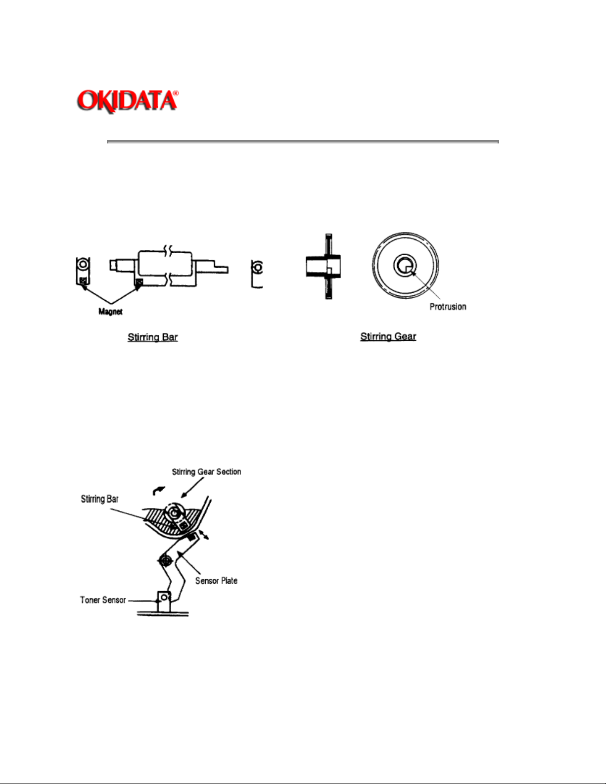
• Device
The Toner Low Detection device consists of a stirring gear which rotates at a constant rate, a stirring bar,
and a magnet on the stirring bar. The stirring bar rotation is driven by the link to the protrusion in the
stirring gear.
• Operation
Toner Low is detected by monitoring the time interval of the encounter of the magnet set on the sensor
lever and the magnet on the stirring bar.
Operation during Toner Full state
• The stirring gear rotates the stirring bar.
• When toner is present, the stirring bar moves through the toner at a constant rate.
Operation during Toner Low state
• When toner is low or empty, the stirring bar rises to the maximum height and then falls to the minimum
height by its own weight. This increases the time of its encounter with the magnet on the sensor lever. By
monitoring this time interval, Toner Low can be detected.
• When the Toner Low state is detected 2 times consecutively, Toner Low is established.
Page 56
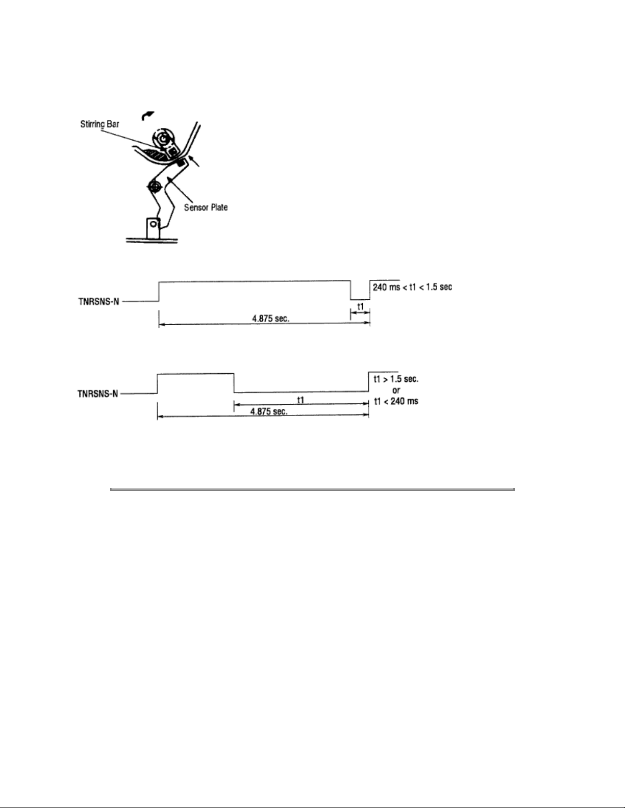
• When the Toner Full state is detected 2 times consecutively, Toner Low is cancelled.
TONER FULL state
TONER LOW state
• When there is no change with the toner sensor for 2 cycles (4.875 sec. x 2) or more, the Toner Sensor
Alarm is activated.
• The toner sensor is not monitored while the drum motor is in halt.
Copyright 1997, Okidata, Division of OKI America, Inc. All rights reserved. See the OKIDATA Business
Partner Exchange (BPX) for any updates to this material. (http://bpx.okidata.com)
Page 57
Page: 30
Service Guide OL600e/610e/610ePS
Chapter 3 Parts Replacement
3. PARTS REPLACEMENT
The section explains the procedures for replacement of parts, assemblies, and units in the field. Only the
disassembly procedures are explained here. For reassembly, reverse the steps of disassembly procedure.
3.1 Precautions for Parts Replacement
Note:
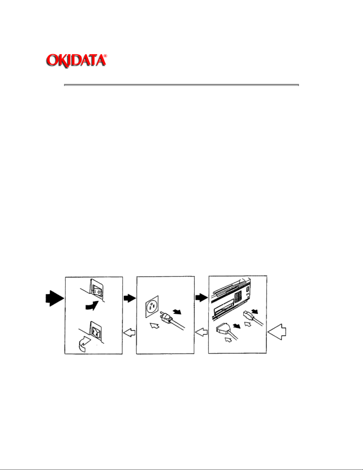
Always use proper anti-static precautions. (1) Before starting the parts replacement, remove the AC
power cord and interface cable.
(a) Remove the AC power cord in the following sequence:
i) Turn off ["O"] the power switch of the printer.
ii) Unplug the power cord from the AC outlet.
iii) Disconnect the power cord and interface cable from the printer.
(b) Reconnect the printer in the following sequence.
i) Connect the AC power cord and interface cable to the printer.
ii) Plug the power cord into the outlet.
iii) Turn on ("l") the power switch.
(2) Do not try to disassemble as long as the printer is operating normally.
(3) Do not remove parts which do not need to be touched; try to keep disassembly to a minimum.
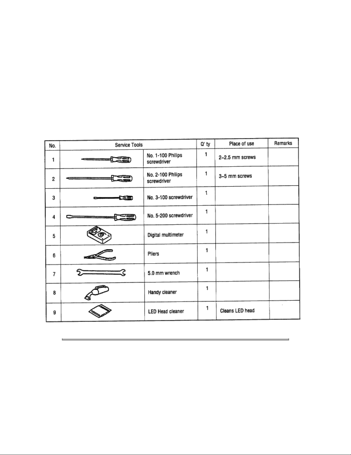
(4) Use specified service tools.
(5) When disassembling, follow the procedure in sequence laid out in this manual. Parts may be damaged
if these sequences are not followed.
Page 58
(6) Since screws, collars and other small parts are likely to be lost, they should temporarily be attached to
the original positions during disassembly.
(7) When handling IC's such as microprocessors, ROM's and RAM's, or circuit boards, use proper
anti-static precautions.
(8) Do not place printed circuit boards directly on the equipment or floor.
[Service Tools]
The tools required for field replacement of printed circuit boards and units are listed in Table 3-1.
Table 3-1 Service Tools
Copyright 1997, Okidata, Division of OKI America, Inc. All rights reserved. See the OKIDATA Business
Partner Exchange (BPX) for any updates to this material. (http://bpx.okidata.com)
Page 59
Service Guide OL600e/610e/610ePS
Chapter 3 Parts Replacement
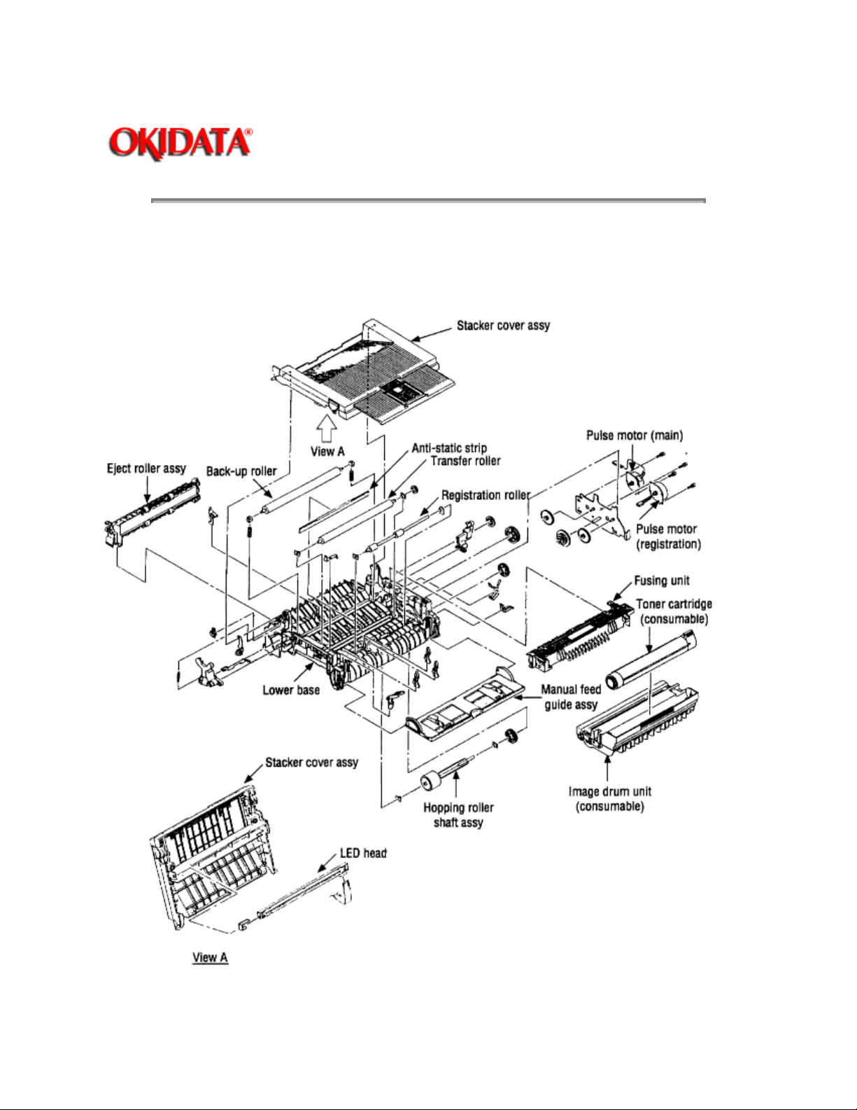
3.2 Parts Layout
This section describes the layout of main parts of the equipment.
[Lower base unit]
Page: 31
Figure 3-1
Page 60

Copyright 1997, Okidata, Division of OKI America, Inc. All rights reserved. See the OKIDATA Business
Partner Exchange (BPX) for any updates to this material. (http://bpx.okidata.com)
Page 61
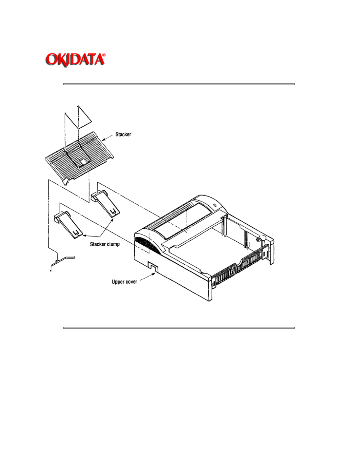
[Upper cover unit]
Page: 32
Service Guide OL600e/610e/610ePS
Chapter 3 Parts Replacement
Figure 3-2
Copyright 1997, Okidata, Division of OKI America, Inc. All rights reserved. See the OKIDATA Business
Partner Exchange (BPX) for any updates to this material. (http://bpx.okidata.com)
Page 62
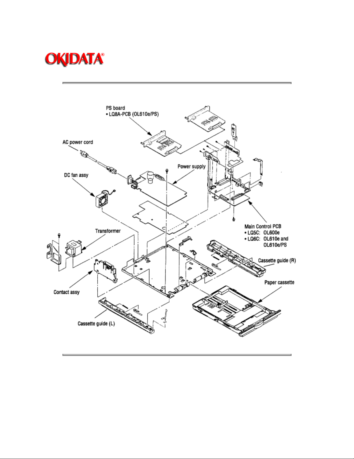
[Base unit]
Page: 33
Service Guide OL600e/610e/610ePS
Chapter 3 Parts Replacement
Figure 3-3
Copyright 1997, Okidata, Division of OKI America, Inc. All rights reserved. See the OKIDATA Business
Partner Exchange (BPX) for any updates to this material. (http://bpx.okidata.com)
Page 63
Page: 34
Service Guide OL600e/610e/610ePS
Chapter 3 Parts Replacement
3.3 How to Change Part
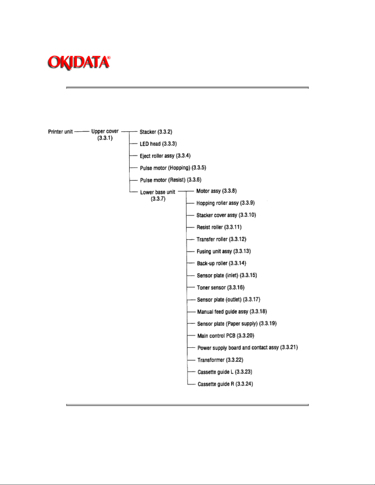
This section explains how to change parts and assemblies listed in the disassembly diagram below.
Copyright 1997, Okidata, Division of OKI America, Inc. All rights reserved. See the OKIDATA Business
Partner Exchange (BPX) for any updates to this material. (http://bpx.okidata.com)
Page 64

Service Guide OL600e/610e/610ePS
Chapter 3 Parts Replacement
3.3.1 Upper Cover
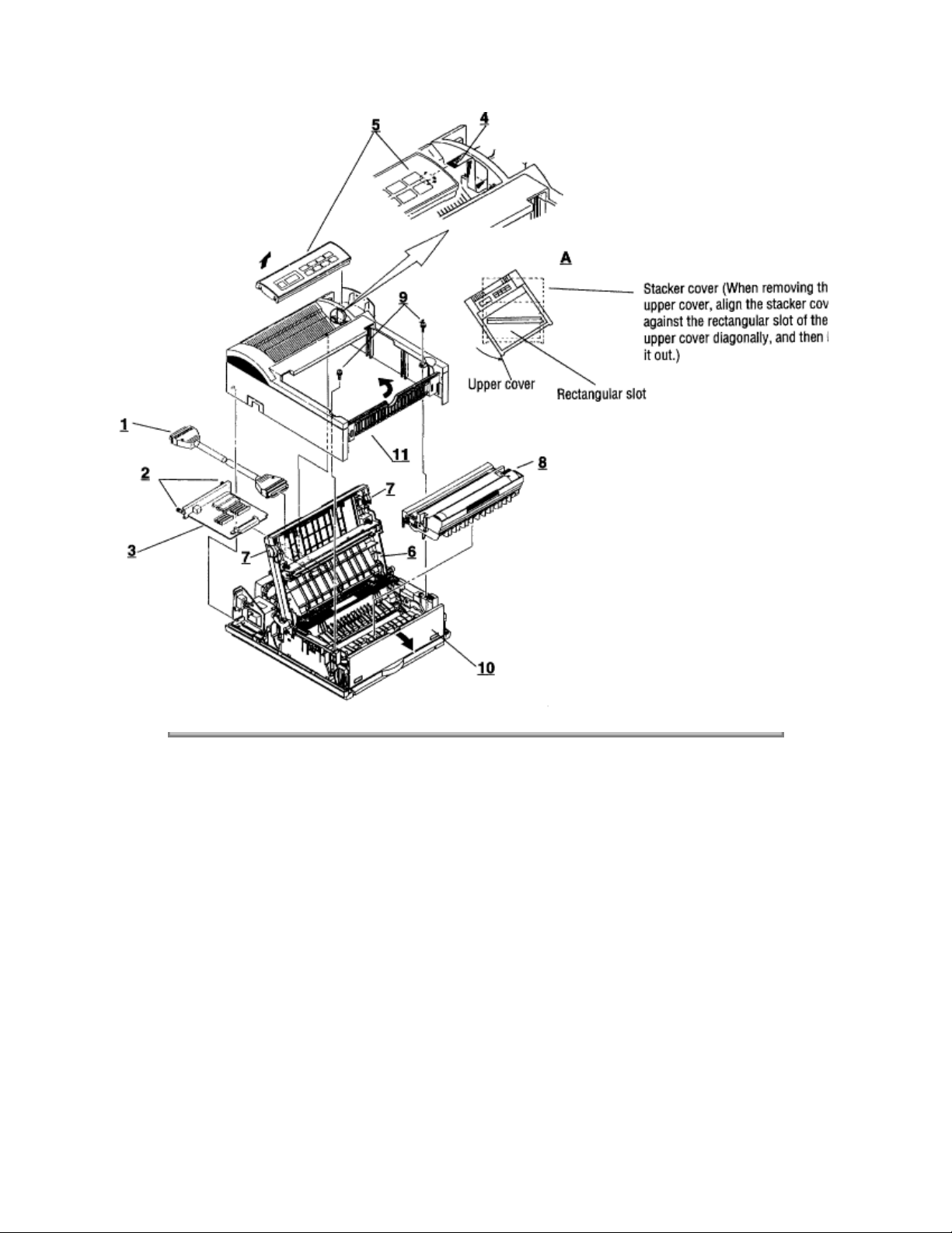
(1) With the power switch turned off, unplug the AC power cord from the outlet.
(2) Disconnect the interface cable 1.
(3) Remove two thumb screws 2 and remove the PS board (OL610e/PS) 3.
(4) If a memory board is installed, remove it.
(5) On the OL610e/PS, disconnect the flexible cable 4 from the connector (CN1) 5 of the operator
panel PCB, and put the cable inside the cover.
(6) Open the stacker cover assembly 6 by pressing the knobs 7 on the left and right sides.
(7) Remove the image drum unit 8.
Page: 35
(8) Remove two screws 9, and open the manual feed guide assy 10. Lift up the front of the upper cover
and release the claws at two locations on the back side. Lift the cover straight up one or two inches, rotate
the cover about 45 degrees to clear the face-up stacker, then lift the cover completely off of the printer
(Detail A).
When removing or installing the upper cover, be careful not to damage the cable 4.
Note:
11
Page 65
Copyright 1997, Okidata, Division of OKI America, Inc. All rights reserved. See the OKIDATA Business
Partner Exchange (BPX) for any updates to this material. (http://bpx.okidata.com)
Page 66
Service Guide OL600e/610e/610ePS
Chapter 3 Parts Replacement
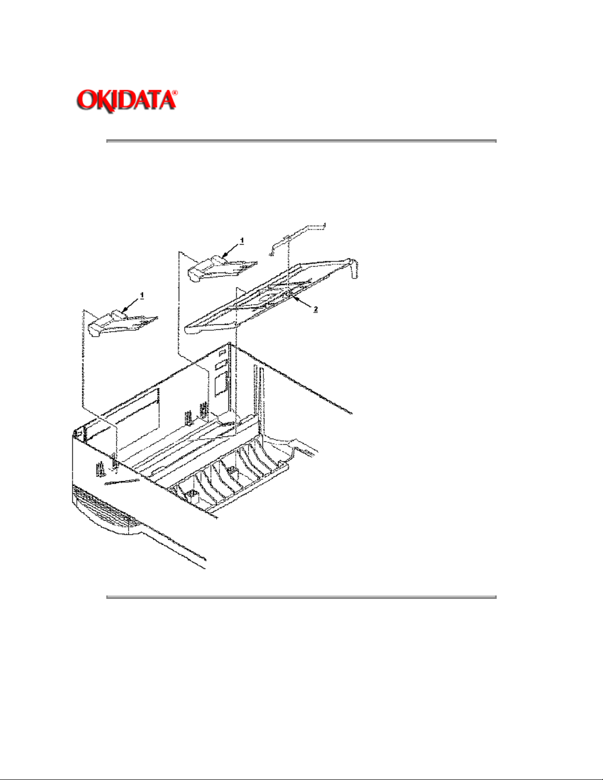
3.3.2 Stacker
(1) Remove the upper cover. (See 3.3.1)
(2) Remove two stacker clamps 1 and the stacker 2 by flexing the upper cover.
Page: 36
Copyright 1997, Okidata, Division of OKI America, Inc. All rights reserved. See the OKIDATA Business
Partner Exchange (BPX) for any updates to this material. (http://bpx.okidata.com)
Page 67

Page: 37
Service Guide OL600e/610e/610ePS
Chapter 3 Parts Replacement
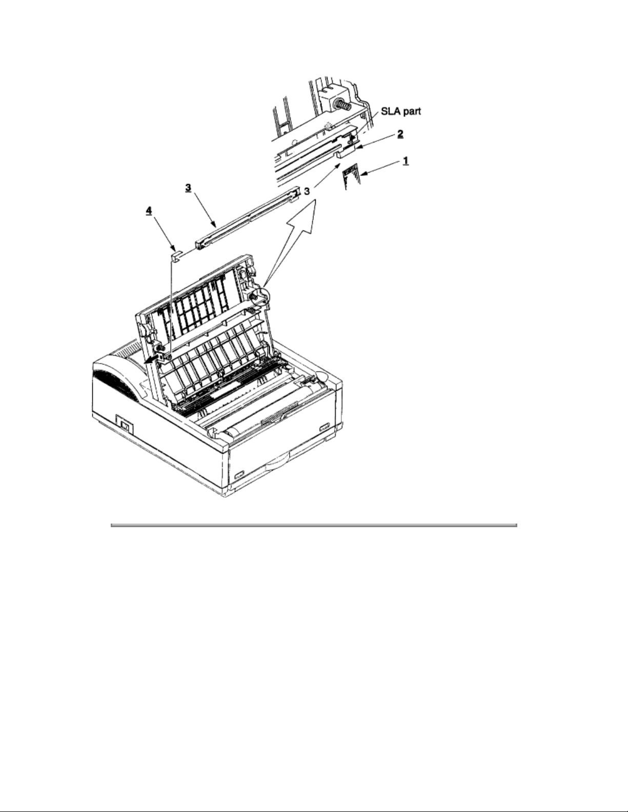
3.3.3 LED Head
(1) Open the stacker cover.
(2) Remove the flexible cable (LED) 1 from the PC connector 2 of the LED head 3.
(3) Remove the LED head by flexing the left side of the upper cover away from the retaining clip.
Be careful to not lose the frame ground clip 4.
Note:
• Be sure not to directly touch or push the SLA (lens) part of the LED head.
Note:
• After mounting the new LED head, set drive time of the LED head according to the marking on the
LED head (see 4.2.1).
• For the installation of the flexible cable (LED) 1, install the PC connector 2 to the flexible cable (LED)
first, then connect the LED head 3 to the PC connector.
• When installing a new LED head, be careful not to lose the frame ground clip 4.
1
Page 68
Copyright 1997, Okidata, Division of OKI America, Inc. All rights reserved. See the OKIDATA Business
Partner Exchange (BPX) for any updates to this material. (http://bpx.okidata.com)
Page 69

Page: 38
Service Guide OL600e/610e/610ePS
Chapter 3 Parts Replacement
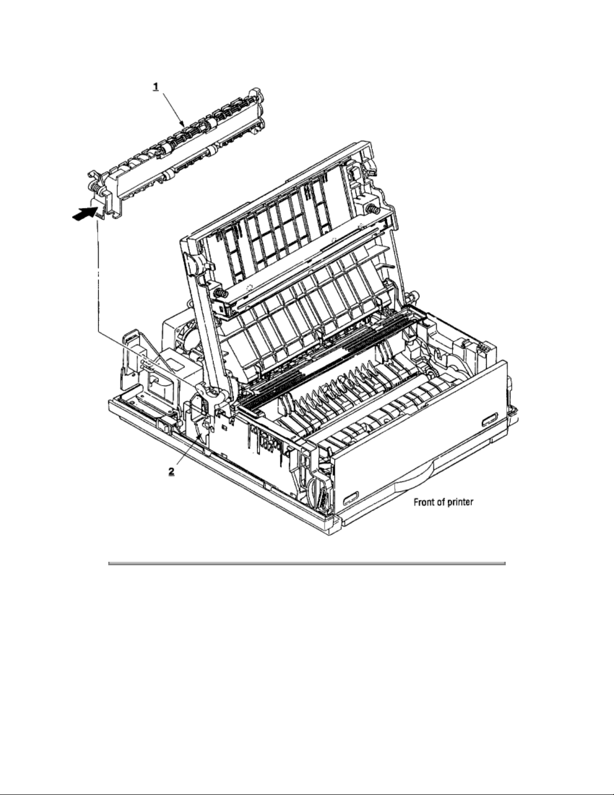
3.3.4 Eject Roller Assy
(1) Remove the upper cover (see 3.3.1). Leave the face-down stacker open.
(2) Using a small flatblade screwdriver, press the clamp on the left side of the eject roller assy 1 in the
direction of the arrow. Detach the eject roller assy from the lower base unit 2, and remove it.
When installing the eject roller, verify that the right side of the roller assembly is properly aligned
Note:
with the main unit.
Page 70
Copyright 1997, Okidata, Division of OKI America, Inc. All rights reserved. See the OKIDATA Business
Partner Exchange (BPX) for any updates to this material. (http://bpx.okidata.com)
Page 71

Service Guide OL600e/610e/610ePS
Chapter 3 Parts Replacement
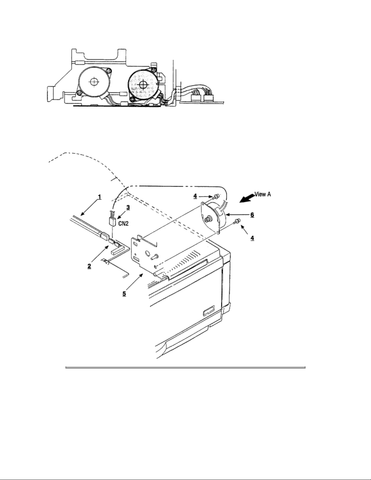
3.3.5 Pulse Motor (Main)
(1) Remove the upper cover (see 3.3.1).
(2) Remove the connector 3 from (CN2) 2 of the Main Control PCB 1.
(3) Remove two screws 4 and remove the pulse motor (main) 6 from the motor bracket 5.
Page: 39
Page 72
Copyright 1997, Okidata, Division of OKI America, Inc. All rights reserved. See the OKIDATA Business
Partner Exchange (BPX) for any updates to this material. (http://bpx.okidata.com)
Page 73

Service Guide OL600e/610e/610ePS
Chapter 3 Parts Replacement
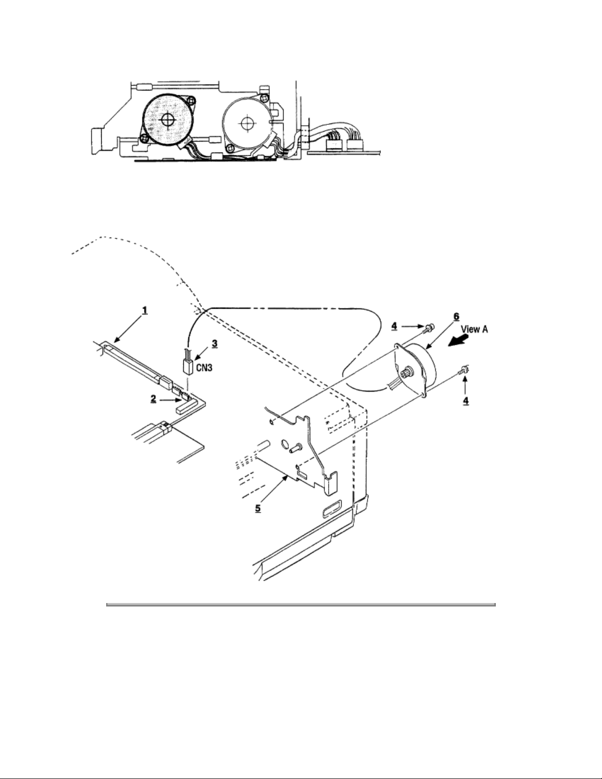
3.3.6 Pulse Motor (Registration)
(1) Remove the upper cover (see 3.3.1).
(2) Remove the connector 3 from (CN3) 2 of the Main Control PCB 1.
(3) Remove two screws 4 and remove the pulse motor (registration) 6 from the motor bracket 5.
Page: 40
Page 74
Copyright 1997, Okidata, Division of OKI America, Inc. All rights reserved. See the OKIDATA Business
Partner Exchange (BPX) for any updates to this material. (http://bpx.okidata.com)
Page 75

Page: 41
Service Guide OL600e/610e/610ePS
Chapter 3 Parts Replacement
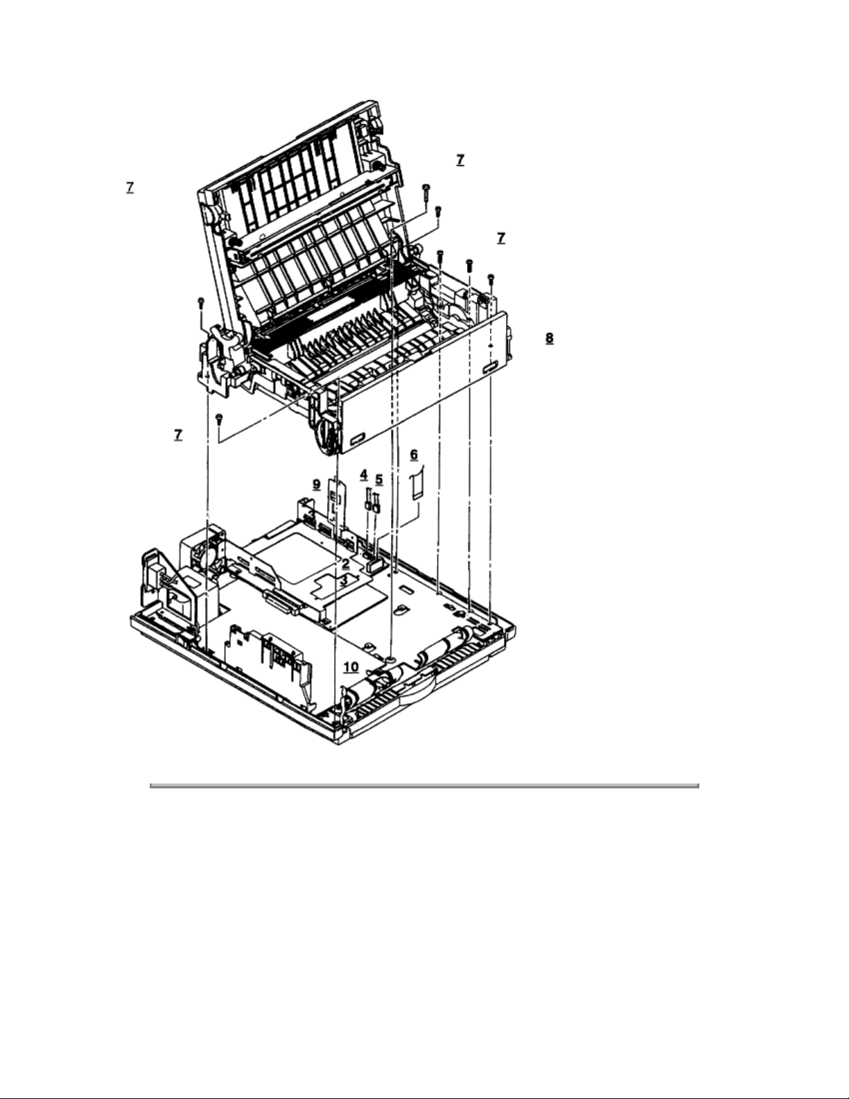
3.3.7 Lower Base Unit
(1) Remove the upper cover (see 3.3.1).
(2) Remove the connecting cables 4 and 5 of the pulse and main motor from the connectors 2 and 3 of the
Main Control PCB 1.
(3) Remove the screw 9 from the grounding cable and the metal shield. The screw is located directly
above CN1 and the 8-pin DIN connector for the second feeder/multi-purpose feeder.
(4) Remove the connector 6 of the LED head from the Main Control PCB 1.
(5) Remove seven screws 7, then remove the lower base unit 8.
Use care when lifting the lower base unit. Do not deform the ground clip
Note:
feeder.
10
for the second sheet
Page 76
Copyright 1997, Okidata, Division of OKI America, Inc. All rights reserved. See the OKIDATA Business
Partner Exchange (BPX) for any updates to this material. (http://bpx.okidata.com)
Page 77
Page: 42
Service Guide OL600e/610e/610ePS
Chapter 3 Parts Replacement
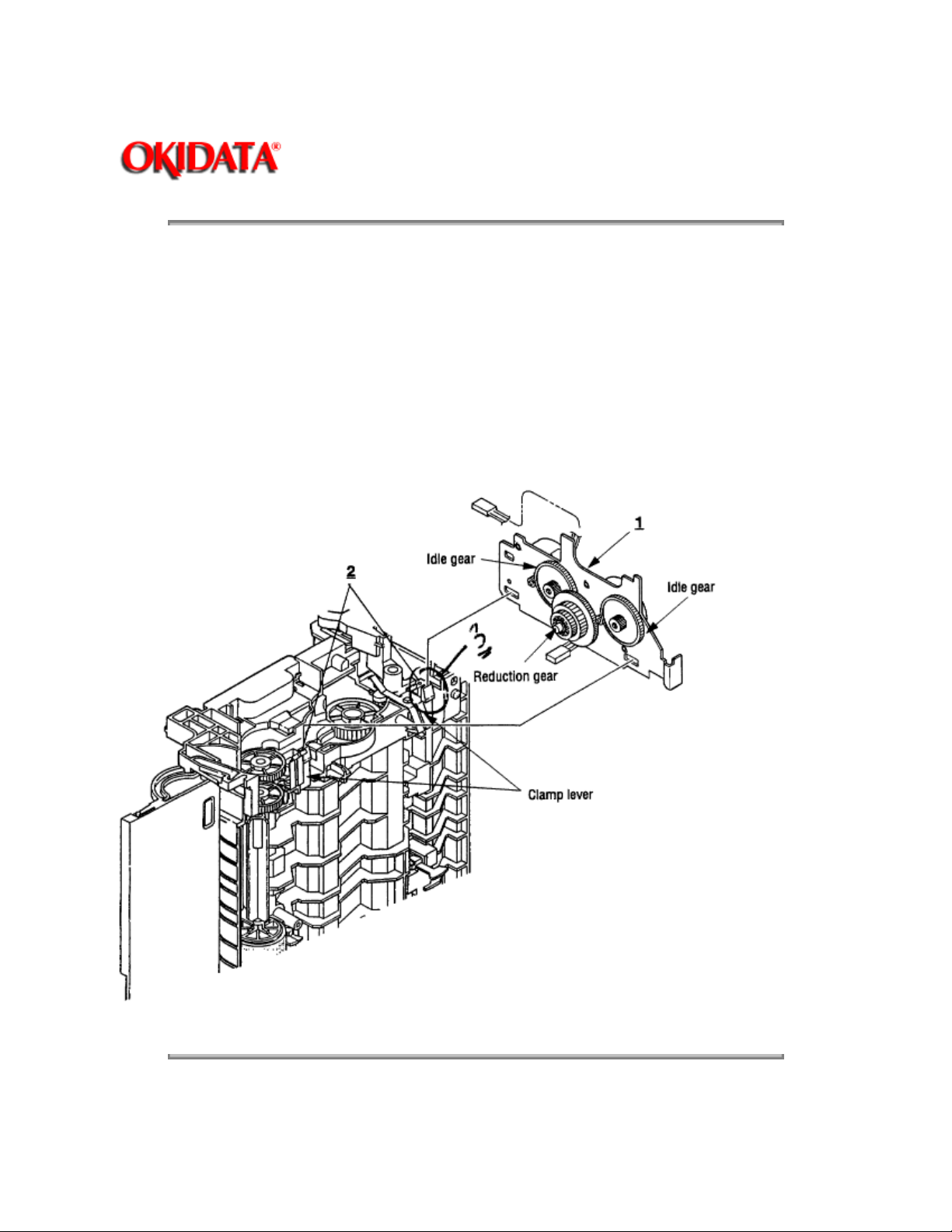
3.3.8 Motor Assy
(1) Remove the upper cover (see 3.3.1).
(2) Remove the lower base unit (see 3.3.7).
(3) Stand the lower base unit on its left side as shown. Free the pulse and main motor cables from the
lower base unit at location 3, , and unlock two clamp levers
2;
then remove the motor assy 1.
Use special care, because the idle gears and the reduction gear are
Note:
will become loose.
permanently attached and
not
Copyright 1997, Okidata, Division of OKI America, Inc. All rights reserved. See the OKIDATA Business
Partner Exchange (BPX) for any updates to this material. (http://bpx.okidata.com)
Page 78

Page: 43
Service Guide OL600e/610e/610ePS
Chapter 3 Parts Replacement
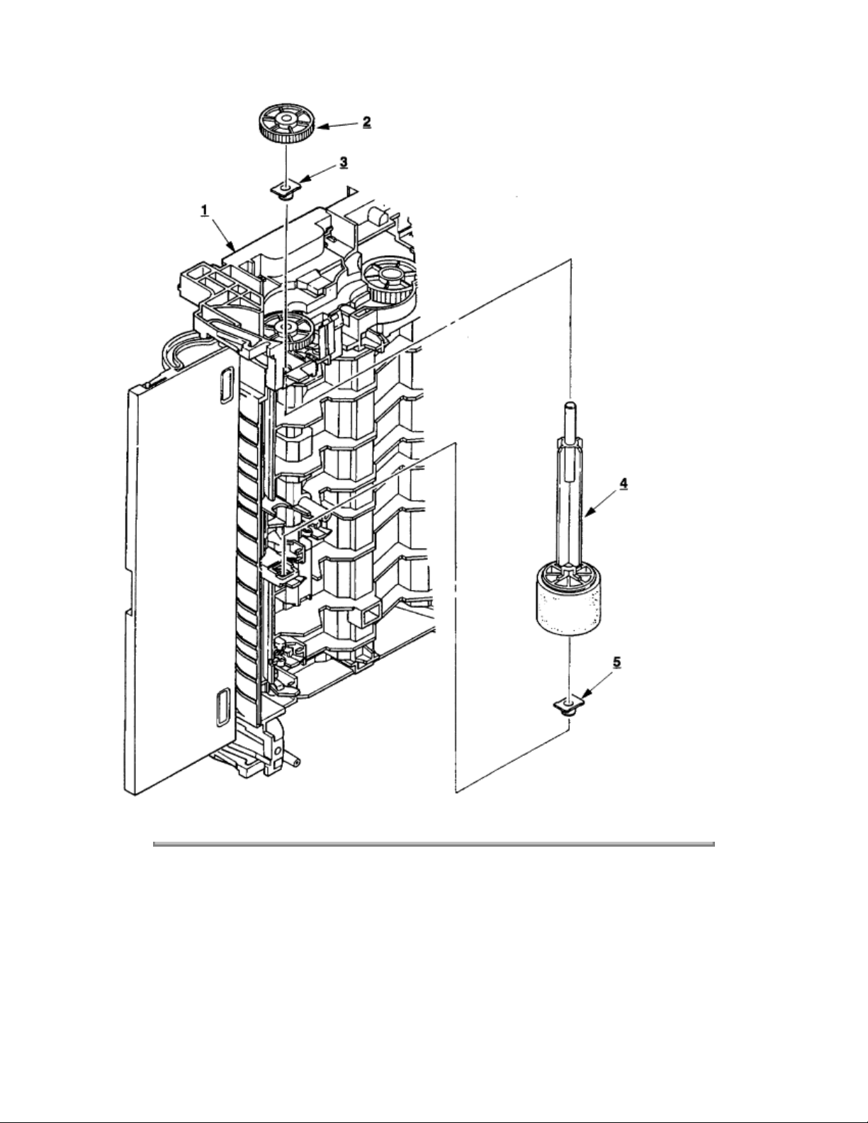
3.3.9 Hopping Roller Assy
(1) Remove the upper cover (see 3.3.1).
(2) Remove the lower base unit (see 3.3.7).
(3) Remove the motor assy (see 3.3.8).
(4) With the lower base unit 1 standing on its side, remove the one-way clutch gear 2 and the bearing (A)
3
, then remove the hopping roller assy 4 and the bearing (B) 5.
Take special note of the orientation and position of the bearings. Do not lose the bearings.
Note:
Page 79
Copyright 1997, Okidata, Division of OKI America, Inc. All rights reserved. See the OKIDATA Business
Partner Exchange (BPX) for any updates to this material. (http://bpx.okidata.com)
Page 80

Page: 44
Service Guide OL600e/610e/610ePS
Chapter 3 Parts Replacement
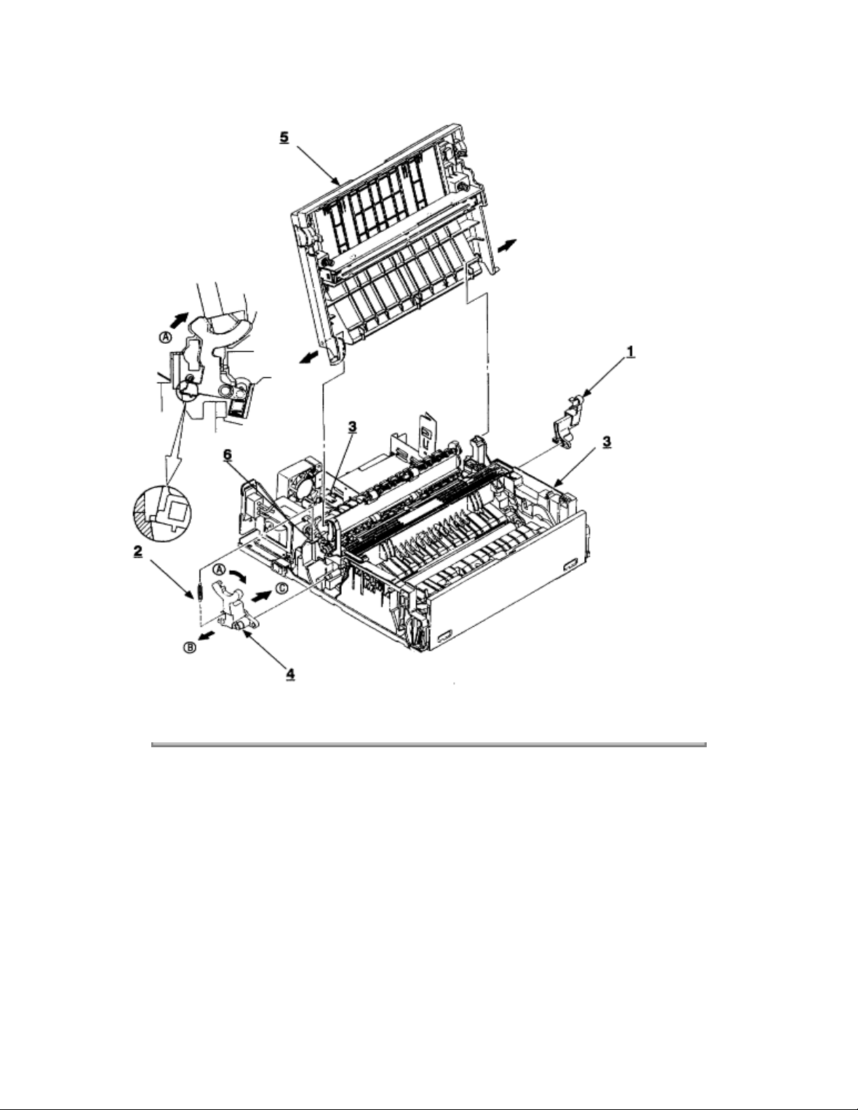
3.3.10 Stacker Cover Assy
(1) Remove the upper cover (see 3.3.1).
(2) Remove the LED head cable from the connector on the Main Control PCB and remove the LED head
grounding screw (see 3.3.7, steps 3 & 4).
(3) Remove the reset lever R 1 . Remove the reset spring 2, then turn L 4 in direction A to release the tabs
on the face-down stacker cover assy 5.
(4) Release two pins of the lower base unit 3, then remove the stacker cover assy 5.
Use care when removing the stacker assy, because the cover close damper 6 is not permanently
Note:
attached.
Page 81
Copyright 1997, Okidata, Division of OKI America, Inc. All rights reserved. See the OKIDATA Business
Partner Exchange (BPX) for any updates to this material. (http://bpx.okidata.com)
Page 82

Page: 45
Service Guide OL600e/610e/610ePS
Chapter 3 Parts Replacement
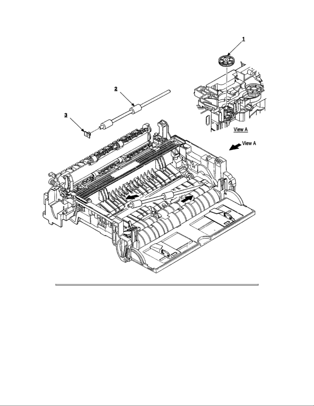
3.3.11 Registration Roller
(1) Remove the upper cover (see 3.3.1).
(2) Remove the lower base unit (see 3.3.7).
(3) Remove the motor assy (see 3.3.8).
(4) With the lower base unit standing on its side (view A), remove the one-way clutch gear 1.
(5) Note the placement of the bearing on the left side of the registration roller. Press the registration roller
2
to the right side (in the direction of the arrow as shown) and lift up the left side. Remove the registration
roller 2 and the bearing (registration) 3.
Page 83
Copyright 1997, Okidata, Division of OKI America, Inc. All rights reserved. See the OKIDATA Business
Partner Exchange (BPX) for any updates to this material. (http://bpx.okidata.com)
Page 84
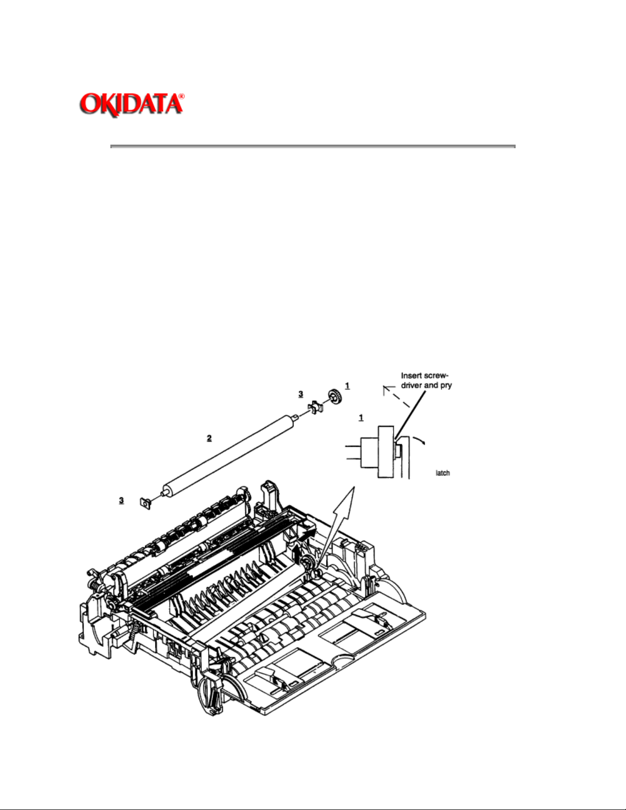
3.3.12 Transfer Roller
Page: 46
Service Guide OL600e/610e/610ePS
Chapter 3 Parts Replacement
Special Note:
surface of the roller.
(1) With the power switch turned off, unplug the AC power cord from the outlet.
(2) Open the stacker cover.
(3) From the top of the machine, release TR gear 1 by unlocking the latch 4 of the main unit with a small
flathead screwdriver (never apply an excessive force when unlocking the latch).
(4) Lift the right side of the transfer roller 2, and shift it to the right side, then pull it out from the main unit
(at this time, the bearings 3 of the left and right sides of the transfer roller 2 will release themselves).
Use great care: the bearings are not permanently
Note:
roller: do not lose or damage the bearing.
Handling the transfer roller unnecessarily will cause poor print quality.
attached. Note:
Use care when removing the
Do not
touch the
Page 85

Copyright 1997, Okidata, Division of OKI America, Inc. All rights reserved. See the OKIDATA Business
Partner Exchange (BPX) for any updates to this material. (http://bpx.okidata.com)
Page 86

Service Guide OL600e/610e/610ePS
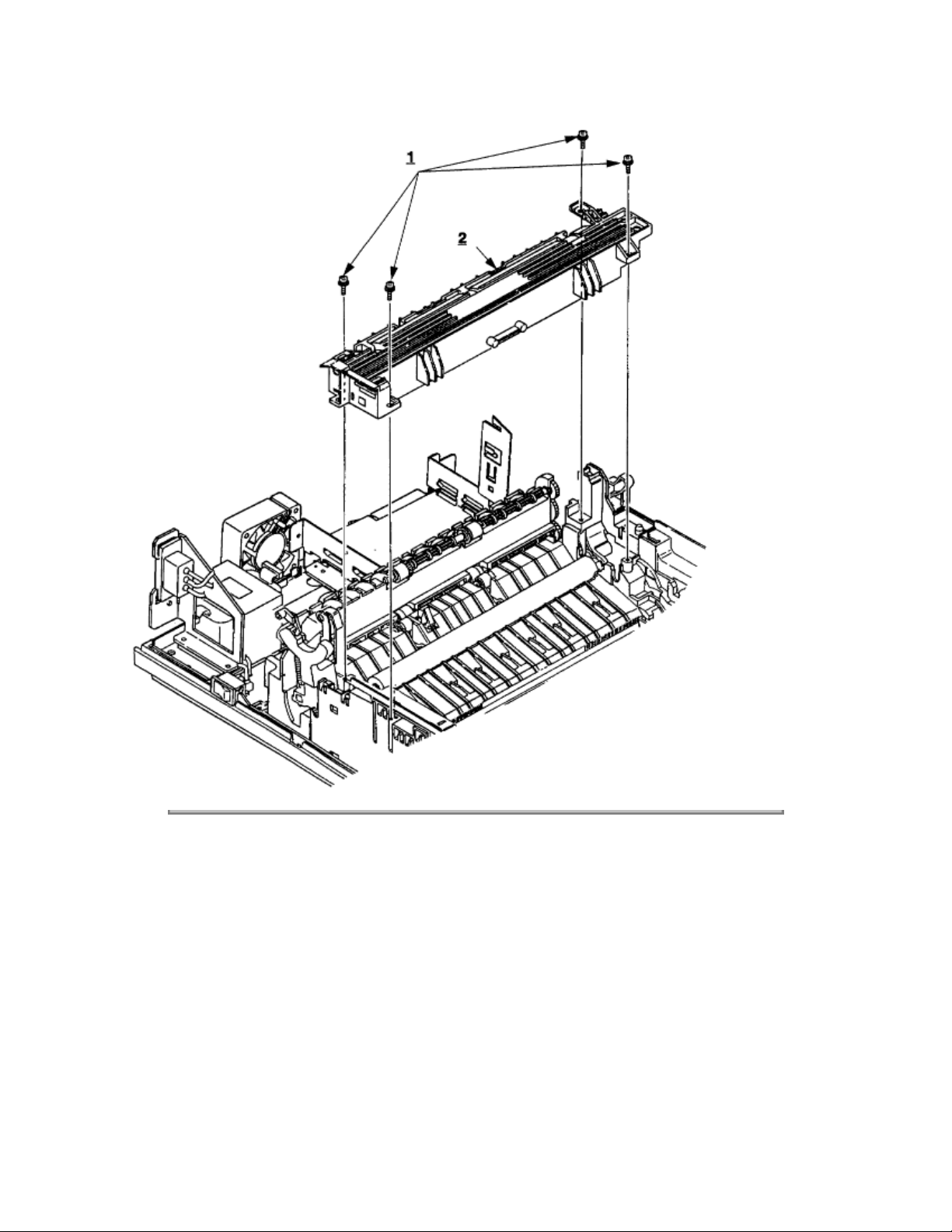
3.3.13 Fusing Unit Assy
(1) Remove the upper cover (see 3.3.1).
(2) Remove the stacker cover assy (see 3.3.10).
(3) Remove four screws 1 and remove the fusing unit 2.
Page: 47
Chapter 3 Parts Replacement
Caution:
Notes:
fusing unit down with your hand. When reinstalling screws 1 , be sure to direct the screws into the
pre-existing hole to avoid damaging the threads. Do not apply excessive torque when tightening the
screws 1; if these screws are stripped, the entire lower unit assembly must be replaced. • When
reinstalling the fuser, insert the left side first, then lower the right side into place.
Fusing unit assy may be hot. Use care when handling.
When installing or removing the fusing unit assy, tighten or loosen the screws while holding the
Page 87
Copyright 1997, Okidata, Division of OKI America, Inc. All rights reserved. See the OKIDATA Business
Partner Exchange (BPX) for any updates to this material. (http://bpx.okidata.com)
Page 88

Page: 48
Service Guide OL600e/610e/610ePS
Chapter 3 Parts Replacement
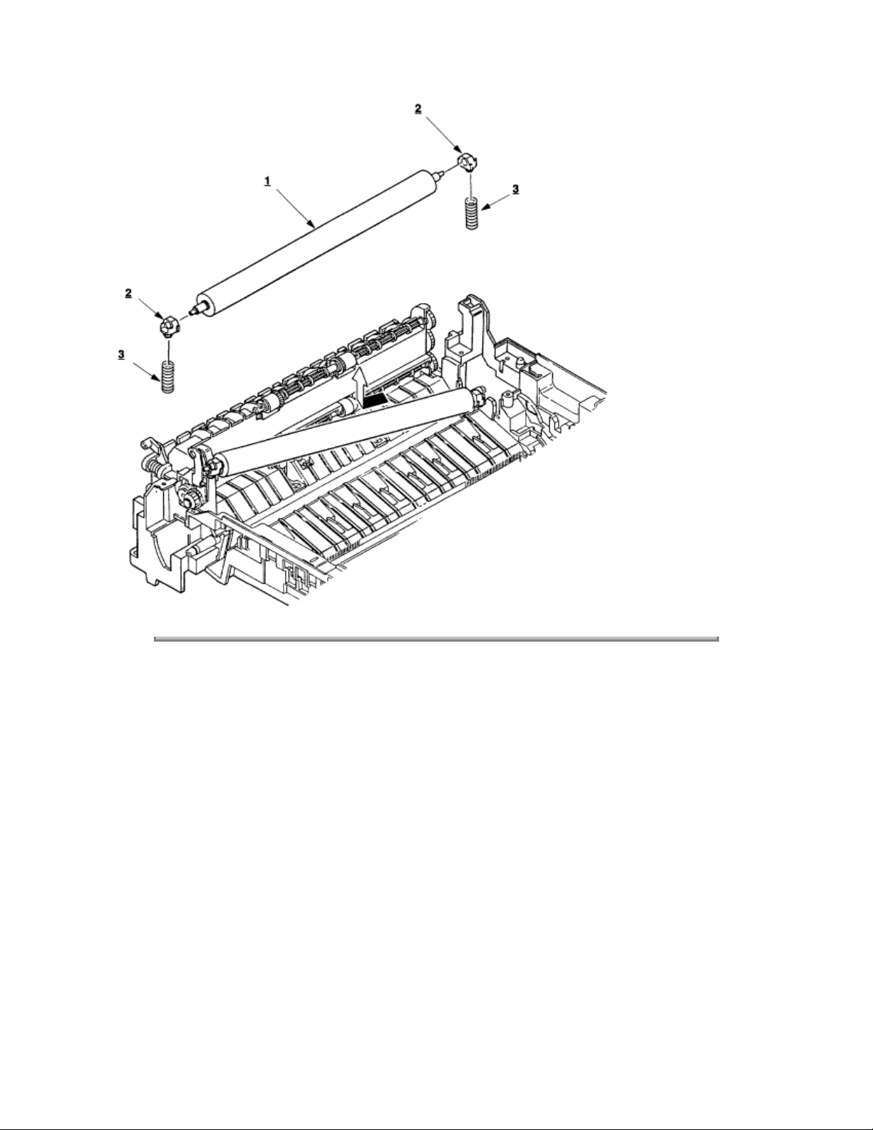
3.3.14 Fusing Pressure Roller
(1) Remove the upper cover (see 3.3.1).
(2) Remove the stacker cover assy (see 3.3.10).
(3) Remove the lower base unit (see 3.3.7).
(4) Remove the fusing unit assy (see 3.3.13).
(5) Remove the motor assy (see 3.3.8).
(6) Remove the reset lever R (see 3.3.10 for location). Press down on the fusing pressure roller to take
pressure off of the reset lever R.
(7) Lift the right side of the fusing pressure roller 1, and pull it out to the right side (at this time, two
bushings 2 and the bias springs 3 will release themselves).
Do not bend or lose springs. Note the orientation and position of the bearings, springs, and ground
Note:
clips.
Page 89
Copyright 1997, Okidata, Division of OKI America, Inc. All rights reserved. See the OKIDATA Business
Partner Exchange (BPX) for any updates to this material. (http://bpx.okidata.com)
Page 90

Page: 49
Service Guide OL600e/610e/610ePS
Chapter 3 Parts Replacement
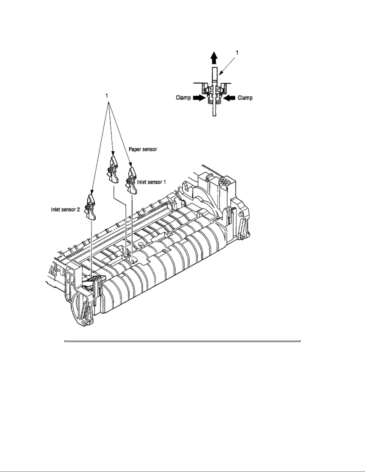
3.3.15 Sensor Plate (Inlet)
(1) Remove the upper cover (see 3.3.1).
(2) Remove the lower base unit (see 3.3.7).
(3) Press the clamps of three sensor plates (inlet) 1, and remove the sensor plates by pressing them
upward from the bottom side.
Page 91
Copyright 1997, Okidata, Division of OKI America, Inc. All rights reserved. See the OKIDATA Business
Partner Exchange (BPX) for any updates to this material. (http://bpx.okidata.com)
Page 92

Service Guide OL600e/610e/610ePS
Chapter 3 Parts Replacement
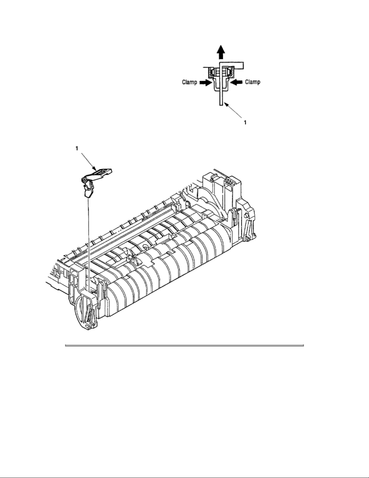
3.3.16 Toner Sensor (Adhesion)
(1) Remove the upper cover (see 3.3.1).
(2) Remove the lower base unit (see 3.3.7).
(3) Press the clamp of the toner sensor 1, and remove the sensor by pushing it up from the bottom.
Page: 50
Page 93
Copyright 1997, Okidata, Division of OKI America, Inc. All rights reserved. See the OKIDATA Business
Partner Exchange (BPX) for any updates to this material. (http://bpx.okidata.com)
Page 94

Page: 51
Service Guide OL600e/610e/610ePS
Chapter 3 Parts Replacement
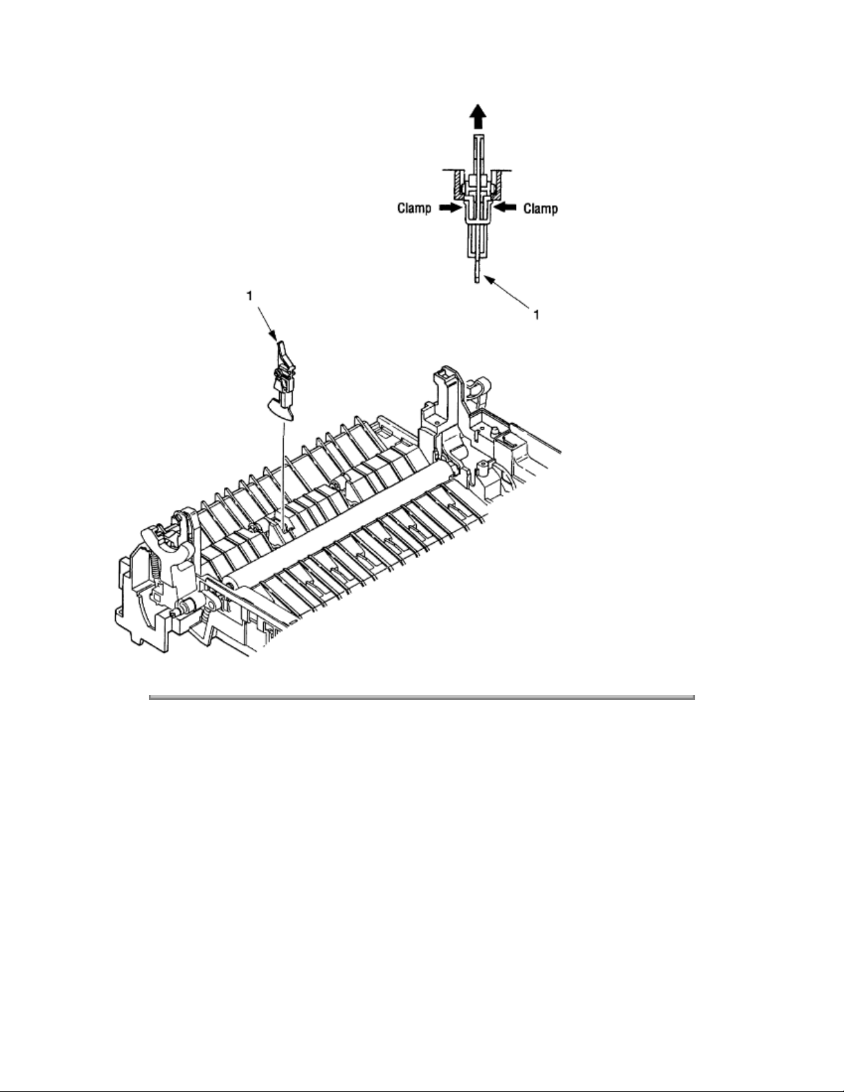
3.3.17 Sensor Plate (Outlet)
(1) Remove the upper cover (see 3.3.1).
(2) Remove the eject roller assy (see 3.3.4).
(3) Remove the lower base unit (see 3.3.7).
(4) Remove the fusing unit assy (see 3.3.13).
(5) Press the clamp of the sensor plates (outlet) 1, and remove the sensor plate by pushing it up from the
bottom.
This is a two-part sensor. Use great care when handling/replacing.
Note:
Page 95
Copyright 1997, Okidata, Division of OKI America, Inc. All rights reserved. See the OKIDATA Business
Partner Exchange (BPX) for any updates to this material. (http://bpx.okidata.com)
Page 96
Page: 52
Service Guide OL600e/610e/610ePS
Chapter 3 Parts Replacement
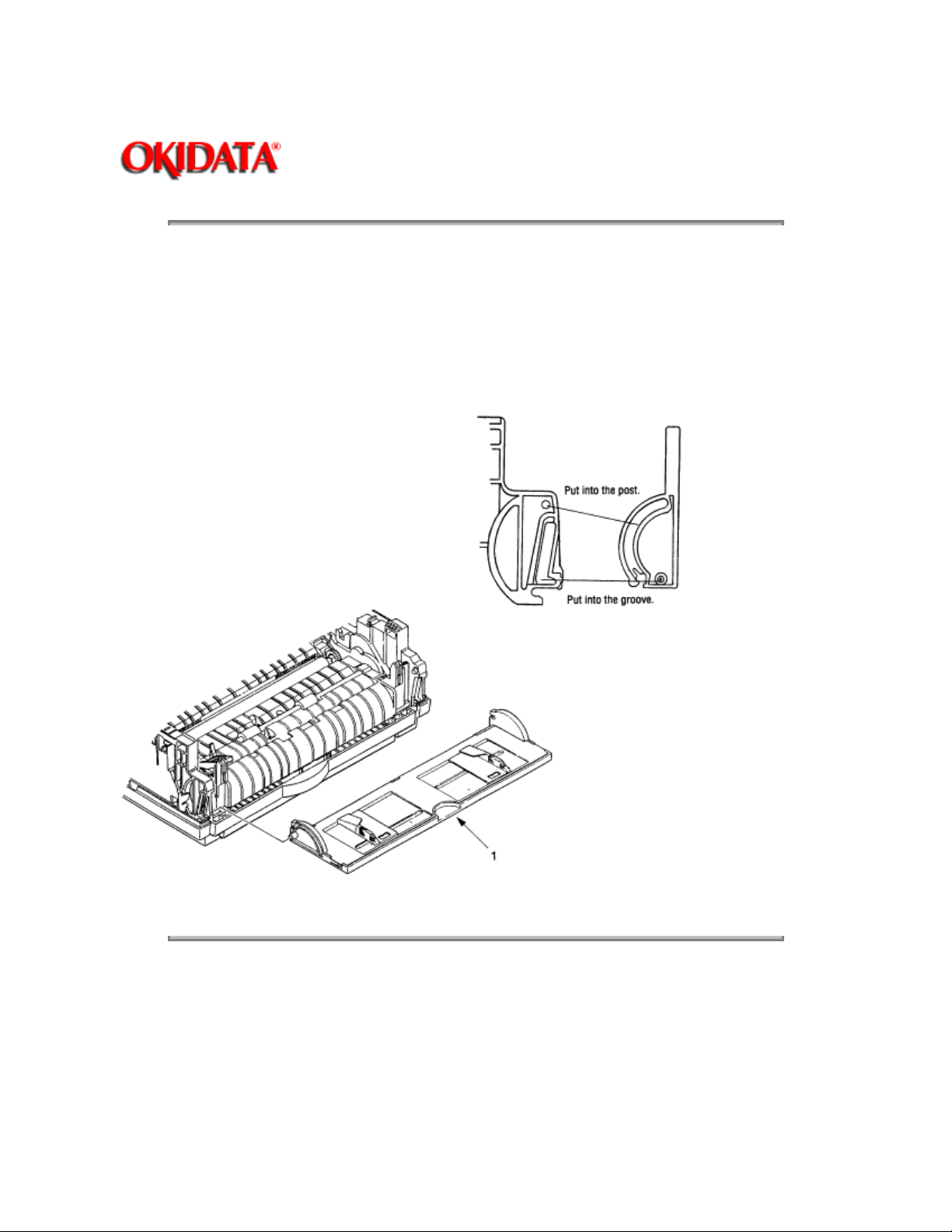
3.3.18 Manual Feed Guide Assy
(1) Remove the upper cover (see 3.3.1).
(2) Open the manual feed guide assembly 1, and release the engagement on both sides with the main unit
by carefully bending the manual feed guide assy 1.
When re-mounting, verify the proper the engagements as shown in the diagram.
Note:
Copyright 1997, Okidata, Division of OKI America, Inc. All rights reserved. See the OKIDATA Business
Partner Exchange (BPX) for any updates to this material. (http://bpx.okidata.com)
Page 97
Service Guide OL600e/610e/610ePS
Chapter 3 Parts Replacement
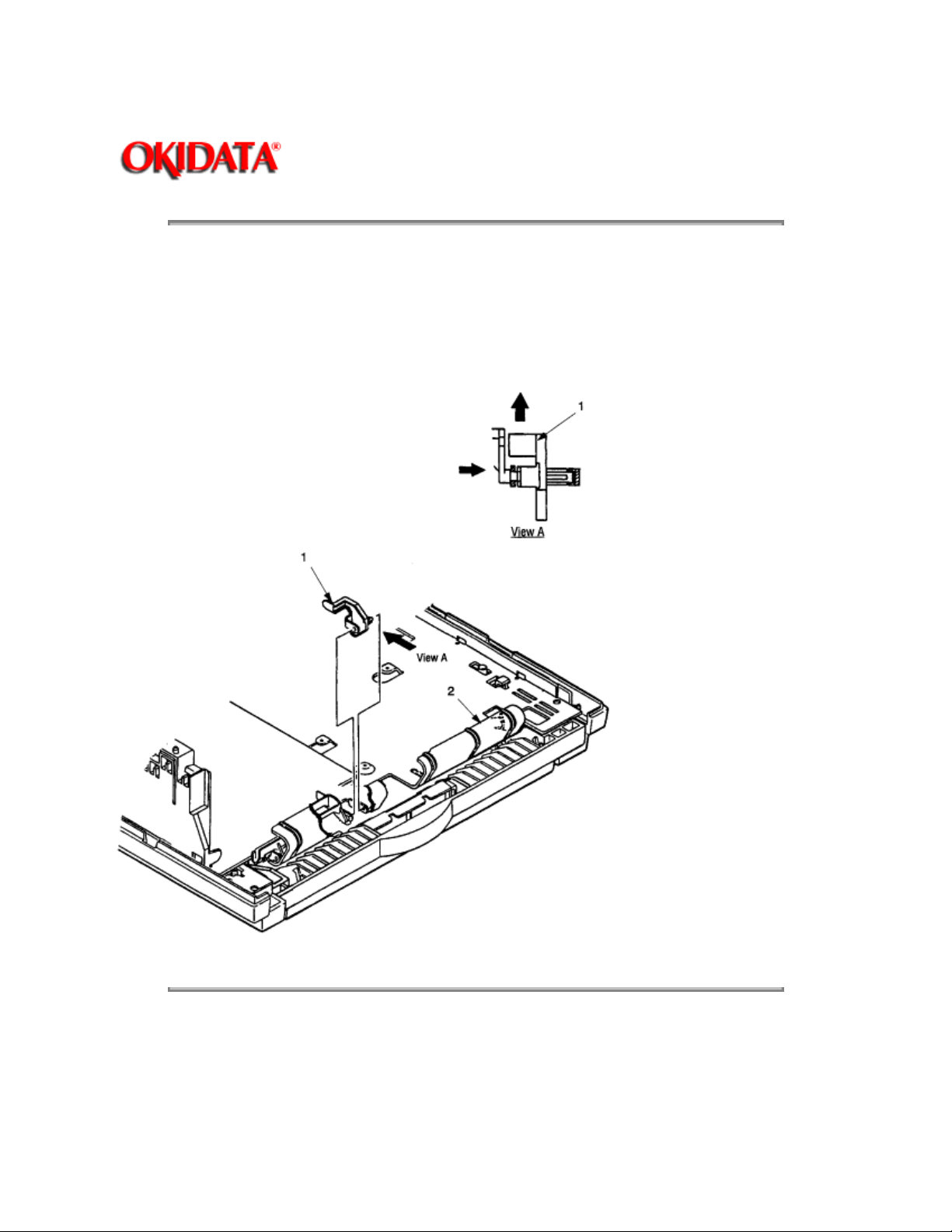
3.3.19 Sensor Plate (Paper Supply)
(1) Remove the upper cover (see 3.3.1).
(2) Remove the lower base unit (see 3.3.7).
(3) Press the clamp of the sensor plate (paper supply) 1, and remove it from the base plate 2.
Page: 53
Copyright 1997, Okidata, Division of OKI America, Inc. All rights reserved. See the OKIDATA Business
Partner Exchange (BPX) for any updates to this material. (http://bpx.okidata.com)
Page 98

Page: 54
Service Guide OL600e/610e/610ePS
Chapter 3 Parts Replacement
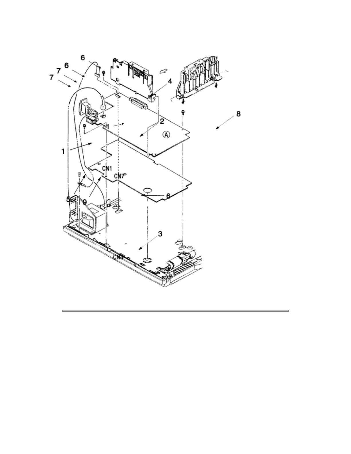
3.3.20 Main Control PCB
The Main Control PCB is different for each model. OL600e : LQ5C-PCB OL610e and OL610e/PS :
LQ6C-PCB
(1) Remove the upper cover (see 3.3.1).
(2) Remove the lower base unit (see 3.3.7).
(3) Remove two screws 1.
(4) Move the Main Control PCB 2 in the direction of arrow A to disconnect it from the power supply board
3
.
(5) Disconnect the LED head cable, the fan motor connector 5, the main motor connector CN2, and the
registration motor connector CN3 from the Main Control PCB CN1. On the OL610e/ PS, disconnect the
operator panel cable. Then remove the Main Control PCB 2 together with the PCB guide plate
4
(6) Remove three screws 6 and two posts 7, and remove the PCB guide plate 4 from the Main Control
PCB 2. Do not bend or lose ground plate 9.
All user settings are lost when the main logic board is changed.
Note:
Page 99
Copyright 1997, Okidata, Division of OKI America, Inc. All rights reserved. See the OKIDATA Business
Partner Exchange (BPX) for any updates to this material. (http://bpx.okidata.com)
Page 100

Page: 55
Service Guide OL600e/610e/610ePS
Chapter 3 Parts Replacement
3.3.21 Power Supply Board and Contact Assy
(1) Remove the upper cover (see 3.3.1).
(2) Remove the lower base unit (see 3.3.7).
(3) Remove the Main Control PCB (see 3.3.20).
(4) Remove the AC inlet 1 from the inlet holder 2, and remove the connector 3 of the transformer from
CN1.
(5) Remove the screw 4, and remove the ground cable 5.
(6) Remove three screws 6, and remove the power supply board 7 and contact assembly 8 at the same
time.
(7) Unlock two claws 9, and remove the contact assembly 8 from the power supply board 7.
Notes:
excessive force to the power switch during reassembly. When reinstalling the power supply/sensor board
onto the base plate, be careful not to bend the mounting tabs
When mounting the lower base unit, be careful around the paper end sensor. Do not apply
10
on the base plate.
 Loading...