

Okidata OL840, OL830, OL820, OL800, OL400 Service Manual
Page: 1
Service Guide OL400
Chapter 0 About This Manual
OL400 / 800 / 820 / 830 / 840
LED Page Printers
Adobe Acrobat printable reference
copy of the OKIDATA Service Training Manual.
09/17/97
Note: This Adobe Acrobat version of the Okidata Service Training Manual was built with the
pictures rendered at 300 dpi, which is ideal for printing, but does not view on most
displays well.
Copyright 1997, Okidata, Division of OKI America, Inc. All rights reserved. See the OKIDATA Business
Partner Exchange (BPX) for any updates to this material. (http://bpx.okidata.com)

Table of Contents Page
Service Guide OL400
0 About This Manual
Front Cover 1
Copyright & Manual Revision 2
Part Number 3
1 Product Specifications
1.1 Overview 4
1.2 Physical Specifications 5
1.3 Print Specifications 6
1.4 Paper Specifications 7
1.5 Power Requirements 8
1.8 Options 9
1.9 Consumables 10
1.10 Reliability Data 11
2 Principles of Operation
2.1 Printer Overview 12
2.2 Main Control Function 13
....2.2.02 Centronics Parallel Interface 14
....2.2.03 RS-232C Serial Interface 15
....2.2.04 Optional Font Card 16
....2.2.05 Optional RAM Board / IC Set 17
2.3 Printer Control Function 18
....2.3.02 Operation Panel 19
....2.3.03 Engine Board 20
....2.3.04 Power Supply Unit 21
....2.3.05 Fuser Unit 22
....2.3.06 Main Motor (Drum Motor) 23
....2.3.07 LED Head 24
....2.3.08 Resist Motor 25
....2.3.09 DC Fan 26
2.4 Mechanical Operation Description 27
....2.4.02 OL400 Printing Process 28
....2.4.03 Process Descriptions 29
2.5 Sensors And Switches 30
....2.5.01 Sensors and Switches 31
....2.5.02 Sensor Functions 32
3 Maintenance & Disassembly
3.1 Maintenance 33
....3.1.02 Maintenance Tools 34
....3.1.03 Maintenance Precautions 35
3.2 Disassembly/Assembly Procedures 36
....3.2.01 Upper Cover 37
....3.2.02 LED Head 38

Table of Contents Page
....3.2.03 Interface Board 39
....3.2.04 RAM Board (Option) 40
....3.2.05 Main Controller Board 41
....3.2.06 Engine Controller Circuit Board (LLAB) 42
....3.2.07 Main Motor 43
....3.2.08 DC Fan Assembly 44
....3.2.09 Idle Gears "A" and "B", and the Reduction Gear 45
....3.2.10 Power Supply Unit 46
....3.2.11 Upper Unit 47
....3.2.12 Fusing Unit 48
....3.2.13 Backup Roller 49
....3.2.14 Transfer Charger Assembly 50
....3.2.15 Resist Roller Assembly 51
....3.2.16 Idle Gear C 52
....3.2.17 Paper Supply Unit 53
....3.2.18 Resist Motor 54
....3.2.19 Engine Connection Board 55
....3.2.20 Hopping Roller 56
....3.2.21 Separator 57
....3.2.22 Ozone Filter 58
3.3 Adjustments And Service Checks 59
....3.3.02 Actual Page Count 60
....3.3.03 Modified Page Count 61
....3.3.04 Vertical Print Start Position Adjustment 62
....3.3.05 Setting the LED Head Drive Time 63
....3.3.06 Voltage Adjustment (+5 vdc) 64
....3.3.07 Darkness Control 65
3.4 Cleaning 66
4 Failure & Repair Analysis
4.1 Overview 67
4.2 Troubleshooting Updates 68
4.3 Reporting Problems 69
4.4 Troubleshooting Tips 70
4.5 Fault Alarms 71
....4.5.02 Error Messages Table 72
....4.5.03 Output SamplesTitle of Section 73
4.6 Repair Analysis Procedures 74
....4.6.02 RAP Index 75
........RAP 01 Printer Does Not Initialize 76
........RAP 02: Paper Feed Jam Alarm 77
........RAP 03: Paper Jam Alarm 78
........RAP 04: Size Tray Error Alarm 79
........RAP 05: Engine Error - Fusing Problem Alarm 80
........RAP 06: Engine Error Alarm 81

Table of Contents Page
........RAP 07: Light or Blurred Images 82
........RAP 09: Blank Output 83
........RAP 10: Vertical Black Stripes 84
........RAP 11: Repeating Marks 85
........RAP 12: Blank Spots 86
........RAP 13: Vertical White Stripes 87
........RAP 14: Black Page 88
........RAP 15: Poor Fusing 89
4.7 Self-Tests 90
A Reference Charts
A.1 Overview 91
A.2 Charts 92
....A.2.01 Main Controller Board (LBPE / LBPF) 93
....A.2.02 Engine Controller Board (LLAB) 94
....A.2.03 Operator Panel PCB (LLDC) 95
....A.2.04 Engine Connection PCB (LLCC) 96
....A.2.05 Centronics Parallel Interface PCB (LLCP / LLCQ) 97
....A.2.06 RS-232C Interface PCB (LLRS) 98
....A.2.07 Expansion RAM Board (optional) (RAMK / RAMH) 99
....A.2.08 Power Interconnect Board (LLIE) 100
....A.2.09 Power Supply Unit 101
B Illustrated Parts Listing
B.1 Illustrated Parts Listing 102
....B.1.02 Definitions of Terms 103
....B.1.03 Parts Ordering Information 104
B.2 Charts 105
....B.2.01 Items 1 - 7 106
....B.2.02 Items 8 - 16 107
....B.2.03 Items 17 - 27, and 41 108
....B.2.04 Items 28 - 35 109
....B.2.05 Items 36 - 40 110

Service Guide OL400
Chapter 0 About This Manual
This document may not be reproduced without written permission of the Okidata® Technical
Training Group. Every effort has been made to ensure the accuracy of the information contained
in this training course. Okidata is not responsible for errors beyond its control.
© 1994 by Okidata All rights reserved.
First Edition, March 1992
Second Edition May, 1994
Written and produced by the Okidata Technical Training Group
Please address any comments on this publication to:
Technical Training Group
Okidata
532 Fellowship Road
Mount Laurel, NJ 08054-3499
Page: 2
Fax Number: (609) 235-2600, ext. 7034
Okilink Login Name: Technical Training
Okidata is a registered trademark of Oki Electric Industry Company, Ltd.; marques deposee de
Oki Electric Industry Company, Ltd.; marca registrada, Oki Electric Industry Company, Ltd.
Microline is a registered trademark of Oki Electric Industry Company, Ltd.
Centronics is a registered trademark of Centronics Inc.
Diablo is a registered trademark of Xerox Corporation
Epson is a registered trademark of Seiko Epson Corporation
IBM is a registered trademark of International Business Machines, Inc.
LaserJet and LaserJet+ are registered trademarks of Hewlett Packard Corporation
Proprinter is a registered trademark of International Business Machines, Inc.
Note: The OL400 Service Training course is part of the OL-Series Training Course and can
not be purchased separately.
Copyright 1997, Okidata, Division of OKI America, Inc. All rights reserved. See the OKIDATA Business
Partner Exchange (BPX) for any updates to this material. (http://bpx.okidata.com)

Page: 3
Service Guide OL400
Chapter 0 About This Manual
Note: The OL400 Service Training course is part of the OL-Series Training Course and can not be
purchased separately.
THE OL400/800/820/830/840 VIDEO TRAINING KIT covers the following
products:
OL400
OL800
OL820
OL830
OL840
The following items are included in the kit:
OL400 Service Handbook
OL800/820 Service Handbook
OL830 Service Handbook
OL840 Service Handbook
Service Training Video
OL400/800/820 User's Documentation
OL830 User's Documentation
OL840 User's Documentation
Price: $95.00 ($124.00 Canadian)
P/N 58226902
Copyright 1997, Okidata, Division of OKI America, Inc. All rights reserved. See the OKIDATA Business
Partner Exchange (BPX) for any updates to this material. (http://bpx.okidata.com)

Service Guide OL400
Chapter 1 Product Specifications
1.1 OVERVIEW
1.1.01 General Information
The OL400 is a desktop, page printer, using a stationary LED head and dry electrophotography as
its exposure and development method. The printer has a resolution of 300 x 300 dots per inch and
a continuous print speed of 4 letter-sized sheets per minute.
A 512K page memory is standard on the OL400; this can be expanded to 1.5 or 2.5 megabyte
with an optional RAM printed circuit board and a memory expansion chip set. Twenty-five resident
fonts are included in the OL400 and five optional font cards are currently available. Downloadable
fonts can also be used with this printer.
The printer can be purchased with either a Centronics parallel interface or an RS-232C serial
interface.
The OL400's consumables consist of the toner kit, which include a toner cartridge, lens cleaner,
and a fuser cleaner pad and the image drum kit which includes the drum cartridge and ozone
filter.
Page: 4
A letter-size paper tray is included with the printer, and legal, and envelope trays are also
available. Paper feeding can be done automatically or manually.
The printer will print on a variety of paper types, labels, envelopes, and transparencies.
Copyright 1997, Okidata, Division of OKI America, Inc. All rights reserved. See the OKIDATA Business
Partner Exchange (BPX) for any updates to this material. (http://bpx.okidata.com)

Page: 5
Service Guide OL400
Chapter 1 Product Specifications
1.2 PHYSICAL SPECIFICATIONS
1.2.01 Outside Dimensions
Width: 17.72"
Height:5.24"
Length: 17.72"
1.2.02 Printer Weight
24 lbs.
1.2.03 LED Array
Number of LED Elements - 2560
Copyright 1997, Okidata, Division of OKI America, Inc. All rights reserved. See the OKIDATA Business
Partner Exchange (BPX) for any updates to this material. (http://bpx.okidata.com)

Service Guide OL400
Chapter 1 Product Specifications
1.3 PRINT SPECIFICATIONS
1.3.01 Print Specifications
Development method: Dry electrophotography
Exposure method: LED stationary head
1.3.02 Print Speed
First print: 28 seconds maximum (letter size)
Continuous print: 4 sheets/minute. (letter size)
Warm-up time: 40 seconds maximum [at room temperature 77oF (25oC) and rated voltage (120
VAC)]
1.3.03 Symbol Sets
Thirty-nine symbol sets are available with the OL400.
1.3.04 Available Fonts
There are twenty-five resident fonts in the OL400.
Page: 6
1.3.05 Paper Feed Method
Automatic feed
Manual Feed
1.3.06 Paper Delivery Method
Face down/face up
1.3.07 Resolution
300 x 300 dots/inch
Copyright 1997, Okidata, Division of OKI America, Inc. All rights reserved. See the OKIDATA Business
Partner Exchange (BPX) for any updates to this material. (http://bpx.okidata.com)

1.4 PAPER SPECIFICATIONS
1.4.01 Paper Types
Letter
Size: 8.5" x 11"
Feed: Automatic or Manual
Weight:Minimum 16 lbs
Maximum 24 lbs
Recommended 20 lbs
Legal
Size: 8.5" x 14"
Feed: Automatic (with optional paper tray) or Manual
Weight:Minimum 16 lbs
Maximum 24 lbs
Recommended 20 lbs
Page: 7
Service Guide OL400
Chapter 1 Product Specifications
Envelope
Size:Minimum 3.5" x 7.5"
Maximum 7.2" x 10.1"
Feed: Automatic (with optional paper tray) or Manual
Weight:Minimum 16 lbs
Maximum 24 lbs
Recommended 20 lbs
Labels
Manual feed / Face up delivery only
Use labels designed specifically for laser/page printers.
Transparencies
Manual feed / Face up delivery only
Must be able to withstand the heat of the fusing process.
Copyright 1997, Okidata, Division of OKI America, Inc. All rights reserved. See the OKIDATA Business
Partner Exchange (BPX) for any updates to this material. (http://bpx.okidata.com)

1.5 POWER REQUIREMENTS
1.5.01 Input Power
120 VAC +5.5%, -15%
220/240 VAC +/-10%
1.5.02 Power Consumption
Approximately 800 W maximum during operation
1.6 ENVIRONMENTAL CONDITIONS
1.6.01 Ambient Temperature and Relative Humidity
While operating:
50° to 89° F
10° to 32° C
20 to 80% Relative Humidity
Page: 8
Service Guide OL400
Chapter 1 Product Specifications
While in storage:
14° to 122° F
10° to 50° C
1.6.02 Printer Noise Level
During operation:
At standby:
1.7 AGENCY APPROVALS
FCC Class B
UL 478 Ver.5
CSA 22.2 220
Copyright 1997, Okidata, Division of OKI America, Inc. All rights reserved. See the OKIDATA Business
Partner Exchange (BPX) for any updates to this material. (http://bpx.okidata.com)
50 dB maximum
43 dB maximum
Service Guide OL400
Chapter 1 Product Specifications
1.8 OPTIONS
1.8.01 RAM Expansion Board
1 megabyte (expands printer memory to 1.5 megabyte)
Technician installed
1.8.02 RAM Expansion Chip Set
Technician installed
1 megabyte memory expansion chip set used in conjunction with the RAM Expansion Board
option. (expands printer memory to 2.5 megabyte)
Page: 9
1.8.03 Font ROM Cards
Tax
Courier
Roman
Prestige Elite
Letter Gothic
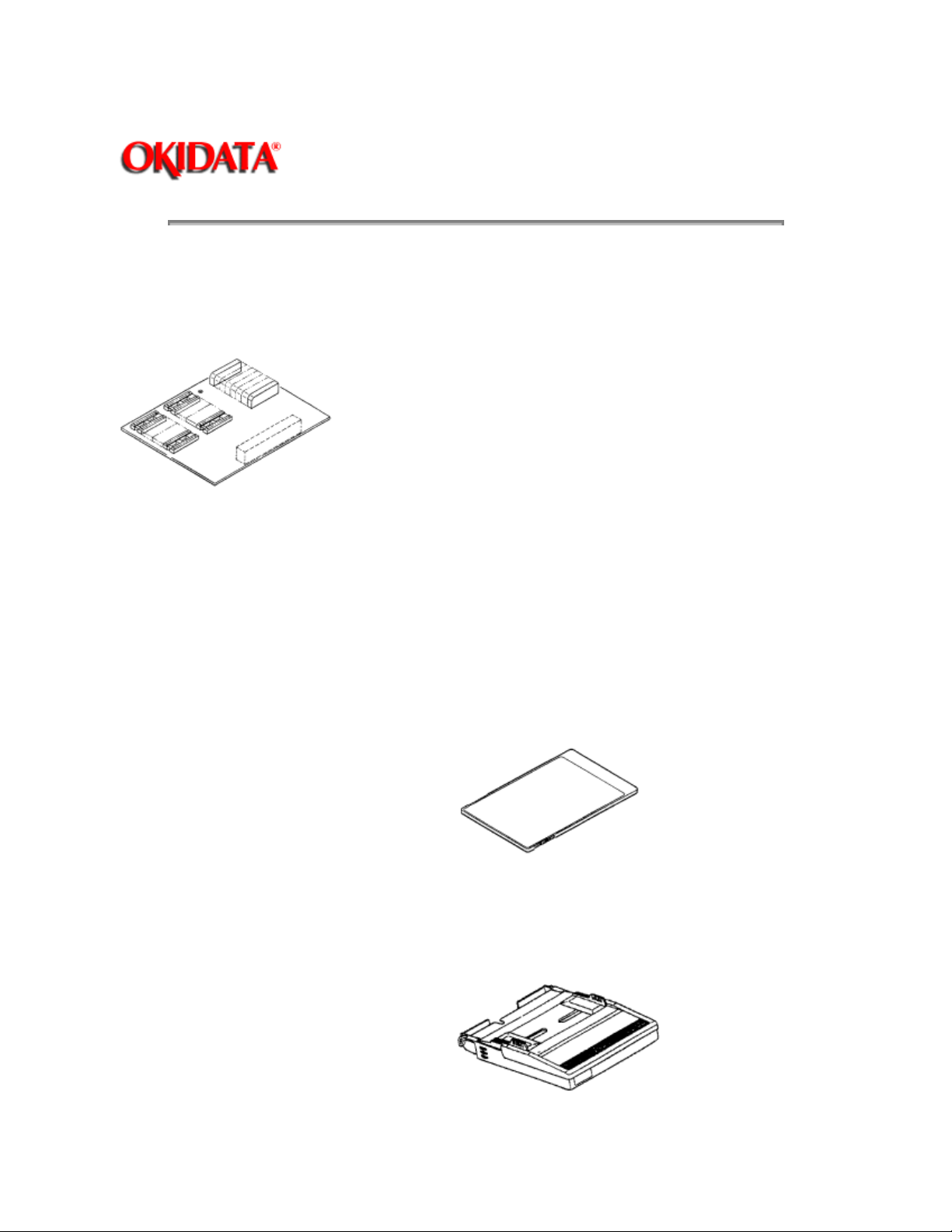
1.8.04 Paper Trays
Letter size
Legal size
Envelope

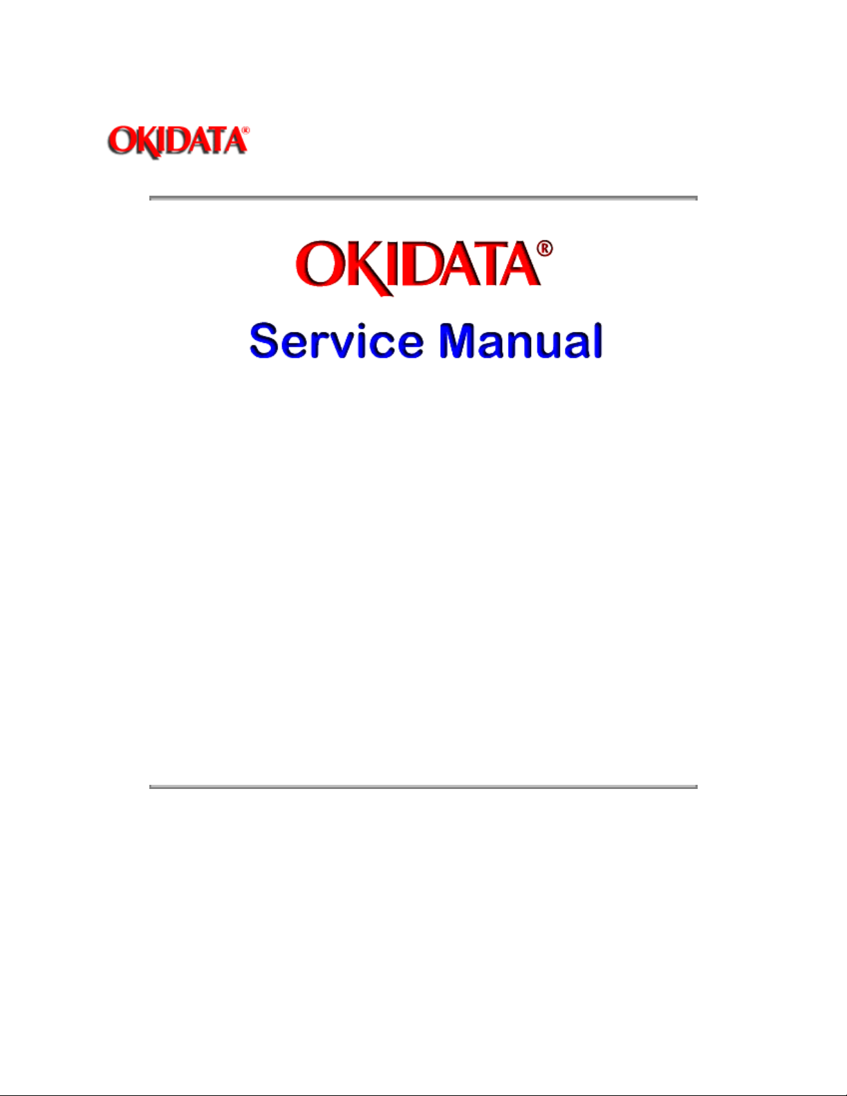
1.8.05 Interface Boards
RS-232C Serial Interface Board
Centronics Parallel Interface Board
Technician installed
Copyright 1997, Okidata, Division of OKI America, Inc. All rights reserved. See the OKIDATA Business
Partner Exchange (BPX) for any updates to this material. (http://bpx.okidata.com)

1.9 CONSUMABLES
Page: 10
Service Guide OL400
Chapter 1 Product Specifications
Toner Cartridge Kit
One Toner Cartridge
One Fuser Cleaner Pad
One LED Head Cleaning Kit
Image Drum Cartridge
One Image Drum Cartridge
One Ozone Filter
Copyright 1997, Okidata, Division of OKI America, Inc. All rights reserved. See the OKIDATA Business
Partner Exchange (BPX) for any updates to this material. (http://bpx.okidata.com)
(P/N 52104201)
(P/N 56106601)

Page: 11
Service Guide OL400
Chapter 1 Product Specifications
1.10 RELIABILITY DATA
1.10.01 Printer Mean Time Between Failure (MTBF)
Approximately 18,000 pages
1.10.02 Printer Mean Time To Repair (MTTR)
Approximately 20 minutes
1.10.03 Estimated Printer Life
Approximately 180,000 pages (5 years)
1.10.04 Printer Duty Cycle
Approximately 3,000 pages @ 5% print density
Copyright 1997, Okidata, Division of OKI America, Inc. All rights reserved. See the OKIDATA Business
Partner Exchange (BPX) for any updates to this material. (http://bpx.okidata.com)

Service Guide OL400
Chapter 2 Principles of Operation
2.1 PRINTER OVERVIEW
2.1.01 General Information
This section describes the operation of the printer in the order listed below.
Page: 12
Main Control Function {
Printer Control Function {
Mechanical Operation {
Sensors and Switches {
Copyright 1997, Okidata, Division of OKI America, Inc. All rights reserved. See the OKIDATA Business
Partner Exchange (BPX) for any updates to this material. (http://bpx.okidata.com)
}
}
}
}

Service Guide OL400
Chapter 2 Principles of Operation
2.2 MAIN CONTROL FUNCTION
2.2.01 General Information
The main control function controls the reception of data from the host interface, processes
command signals, processes the image signals, controls the printer unit, outputs data, and
controls the operation panel.
The main control function consists of the items listed below.
CPU 80186-8
Font ROM (512 kbytes)
Page buffer (512 kbytes)
DRAM controller chip (MSM73V007)
Print controller chip (MSM75HJ014)
Font controller chip (MSM60791)
Programmable I/O (82C55A-2GS)
Interface Control
Centronics Parallel Interface Board
RS-232C Serial Interface Board
Optional Font Card
Optional RAM
Page: 13
Copyright 1997, Okidata, Division of OKI America, Inc. All rights reserved. See the OKIDATA Business
Partner Exchange (BPX) for any updates to this material. (http://bpx.okidata.com)

Service Guide OL400
Chapter 2 Principles of Operation
2.2.02 Centronics Parallel Interface
The following operations are carried out during SELECT mode once the STB-N signal is received
from the host interface.
The BUSY-P signal is sent to the host interface.
Simultaneously with fetching data to the Q4 IC at the last transition of the STB signal, the
RXIPT-P signal is sent to the CPU to inform it of receipt of data.
The CPU reads data received from the Q4 IC by the RD-N signal, and turns off the BUSY signal
to the host interface.
Upon turning off the BUSY signal, the ACK-N signal is sent to the host interface to acknowledge
reception processing.
Page: 14
Copyright 1997, Okidata, Division of OKI America, Inc. All rights reserved. See the OKIDATA Business
Partner Exchange (BPX) for any updates to this material. (http://bpx.okidata.com)

Page: 15
Service Guide OL400
Chapter 2 Principles of Operation
2.2.03 RS-232C Serial Interface
The 8251 Universal Synchronous/Asynchronous Receiver Transmitter is used as a controller.
This serial I/F converts serial data received from the host I/F into parallel data for use by the CPU.
It also converts parallel data from the CPU into serial data to be sent to the Host I/F.
READY/BUSY or X-ON/X-OFF are used as the communication protocol between the Host I/F and
OL400. These can be selected through the Menu.
The baud rate, character length, parity check, stop bit, etc., are automatically written into the
82C51 from the menu, so hardware switches are not required.
Copyright 1997, Okidata, Division of OKI America, Inc. All rights reserved. See the OKIDATA Business
Partner Exchange (BPX) for any updates to this material. (http://bpx.okidata.com)

Page: 16
Service Guide OL400
Chapter 2 Principles of Operation
2.2.04 Optional Font Card
In addition to the twenty-five resident fonts, an optional font IC card is available.
The CD-N signal detects the option font card.
Copyright 1997, Okidata, Division of OKI America, Inc. All rights reserved. See the OKIDATA Business
Partner Exchange (BPX) for any updates to this material. (http://bpx.okidata.com)

Page: 17
Service Guide OL400
Chapter 2 Principles of Operation
2.2.05 Optional RAM Board / IC Set
The expansion RAM board contains 1 Mbyte of memory and sockets for an additional 1 Mbyte.
This RAM is in addition to the 512 Kbyte on the Main Control Board.
Copyright 1997, Okidata, Division of OKI America, Inc. All rights reserved. See the OKIDATA Business
Partner Exchange (BPX) for any updates to this material. (http://bpx.okidata.com)

Service Guide OL400
Chapter 2 Principles of Operation
2.3 PRINTER CONTROL FUNCTION
2.3.01 General Information
The principle hardware components of the printer unit consist of the items listed below.
Operation Panel
Engine Board
Power Supply Unit
Fuser Unit
Main Motor
LED Head
Resist Motor
DC Fan
Page: 18
Copyright 1997, Okidata, Division of OKI America, Inc. All rights reserved. See the OKIDATA Business
Partner Exchange (BPX) for any updates to this material. (http://bpx.okidata.com)

Service Guide OL400
Chapter 2 Principles of Operation
2.3.02 Operation Panel
The following components make up the operation panel.
4-bit MPU (LC6543C)
LCD control driver (MSM6222B or HD44780)
LCD display (16 characters per line)
Operation panel sheet
LEDs (for online mode indication)
Operation buttons
The LCD control driver (MSM622B or HD44780) converts 4-bit character codes received from the
MPU into 8-bit character codes and retrieves the character pattern data (font) associated with the
8-bit character codes from the internal character generator for display on the LCD.
Operation Panel Interface
The operation panel is controlled by the operation panel interface located on the Main Control
Board via the Engine Board.
Page: 19
Copyright 1997, Okidata, Division of OKI America, Inc. All rights reserved. See the OKIDATA Business
Partner Exchange (BPX) for any updates to this material. (http://bpx.okidata.com)

Service Guide OL400
Chapter 2 Principles of Operation
2.3.03 Engine Board
The Engine Board is composed of the items listed below.
MPU80C51, or MPU83C154 (8-bit CPU)
LLAB Revision 11
The MPU 83C154 contains the printer control program in its internal ROM.
Therefore, the external ROM (Q1) is not required on Revision 11.
MSM73H019GS (80 pin LSI)
EPROM (Printer Control Program)
EPROM
This 1-Kbit electrically erasable PROM (EEPROM) is loaded with the following data:
Total number of sheets printed after installation
Total number of sheets printed with the current drum
Total number of sheets printed with the current fuser
Setting of time required from the completion of printing to Stand-by
Feed length needed to feed the paper to a printable position.
Print starting line on paper (Top margin)
LED head drive time.
Page: 20
NOTE
:
The EEPROM preserves the above data while the supply voltage is off.
The count of the total number of sheets printed after installation cannot be reset.
The count of the total number of sheets printed with the drum currently in use should be
taken as a rough measure of the useful life of the drum.
It is reset to zero when the drum is replaced by holding down the RESET button and
applying power to the printer.
Copyright 1997, Okidata, Division of OKI America, Inc. All rights reserved. See the OKIDATA Business
Partner Exchange (BPX) for any updates to this material. (http://bpx.okidata.com)

Service Guide OL400
Chapter 2 Principles of Operation
2.3.04 Power Supply Unit
The power supply unit generates the following voltages from the AC input voltage.
Voltage Purpose
+5vdc Logic Levels, LED Head Drive Voltage
+12vdc Interface Line Voltage
-12vdc Interface Line Voltage
+38vdc Motor/Fan Drive Voltage: High Voltage Source
+5Kvdc Transfer Charge Voltage
-6Kvdc Drum Charge Voltage
-600vdc Charge Grid Voltage
-550, -400vdc Developer Bias Voltages
High Voltage Drive
The high voltage circuit provides a charge voltage (about -6Kvdc), a transfer voltage (about +5
Kvdc), a grid voltage (about -600 vdc), and a developer bias voltages (about -550vdc and
-400vdc). Of these voltages, the first two are generated from a high voltage power supply. The
grid connects to the ground via a varistor on the medium-voltage generation circuit (LLAB-PCB). It
is kept at about -680 vdc during charging.
Page: 21
Copyright 1997, Okidata, Division of OKI America, Inc. All rights reserved. See the OKIDATA Business
Partner Exchange (BPX) for any updates to this material. (http://bpx.okidata.com)

Page: 22
Service Guide OL400
Chapter 2 Principles of Operation
2.3.05 Fuser Unit
The fuser unit heater is controlled by a thermistor, a comparator, an LSI, and a CPU to keep the
heat roller surface temperature within a predetermined range (about 150 degrees). A thermostat
within the fuser unit prevents abnormal temperature rises in the fuser unit if the thermistor fails.
NOTE:
The CPU checks for a blown or shorted wire in the thermistor at power-on , setting a fuser alarm if
an error is detected.
The CPU also sets a fuser alarm if the proper temperature is not attained within a specified period
of time after power-on.
Upon detecting a fuser alarm, the CPU will halt (after printing the current page).
Copyright 1997, Okidata, Division of OKI America, Inc. All rights reserved. See the OKIDATA Business
Partner Exchange (BPX) for any updates to this material. (http://bpx.okidata.com)

Page: 23
Service Guide OL400
Chapter 2 Principles of Operation
2.3.06 Main Motor (Drum Motor)
The main motor is driven by the motor drive IC (M54646). It is a two-phase motor, driven by the
DM-PH1 and DM-PH2 signals.
Copyright 1997, Okidata, Division of OKI America, Inc. All rights reserved. See the OKIDATA Business
Partner Exchange (BPX) for any updates to this material. (http://bpx.okidata.com)

Page: 24
Service Guide OL400
Chapter 2 Principles of Operation
2.3.07 LED Head
Data on the 2,560 LEDs in the LED head is set in the shift register by the HD CLK signal. The
data is loaded in the latch circuit by the HD LD signal.
The on/off states of the LEDs are controlled by the signals STB1- STB4; 640 bits are turned on or
off at a time.
Copyright 1997, Okidata, Division of OKI America, Inc. All rights reserved. See the OKIDATA Business
Partner Exchange (BPX) for any updates to this material. (http://bpx.okidata.com)

Page: 25
Service Guide OL400
Chapter 2 Principles of Operation
2.3.08 Resist Motor
The resist motor is driven clockwise (Hopping), then counterclockwise (Paper Feed) by the motor
drive IC (LB1731). It is four-phase motor, driven according to the RM-H1, RM-H2, and RM ON-P
signals.
Copyright 1997, Okidata, Division of OKI America, Inc. All rights reserved. See the OKIDATA Business
Partner Exchange (BPX) for any updates to this material. (http://bpx.okidata.com)

Service Guide OL400
Chapter 2 Principles of Operation
2.3.09 DC Fan
The fan is controlled by the FAN ON-P signal from the LSI (MSM73H019). In order for the fan to
operate, the signal FAN SENSE-N must be active.
NOTE:
The fuser and the fan are not driven when the cover is open (reset).
If the fan fails to run, the fuser will turn off and an alarm is set. This prevents the next printout. If
the signal Fan Sense-N becomes inactive while printing, both the heater and the fan come to a
halt after the end of printout of the current page.
A fan alarm is generated when the fan is not sensed at power-on time.
The fan is driven for 1 minute after the fuser has been turned off. The fan speed is reduced if the
next PRINT signal is not received within 1 minute.
Page: 26
Copyright 1997, Okidata, Division of OKI America, Inc. All rights reserved. See the OKIDATA Business
Partner Exchange (BPX) for any updates to this material. (http://bpx.okidata.com)
 Loading...