

OKIDATA OL1200ex Service Manual
Chapter 1
%1. Configuration
1. CONFIGURATION
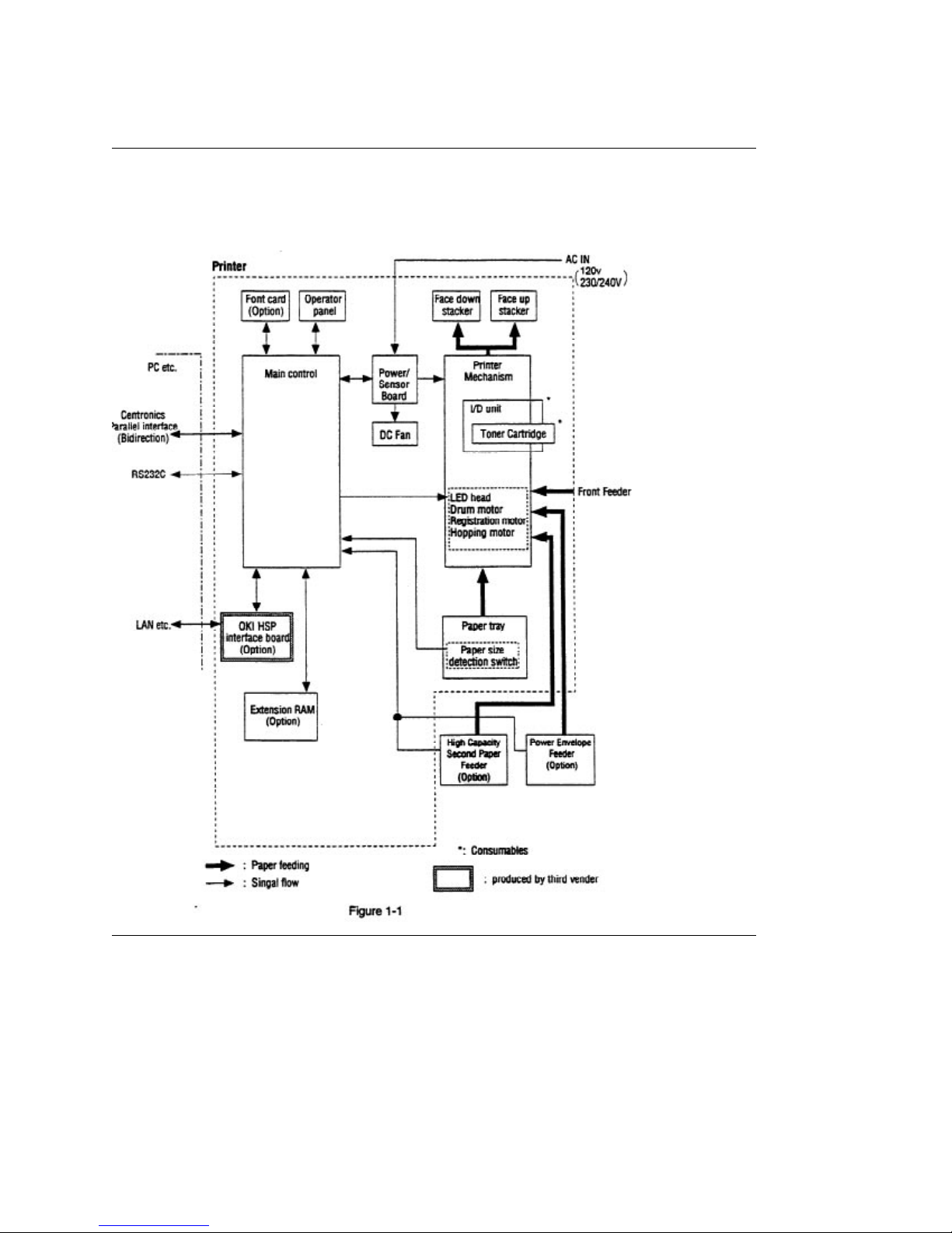
1.1 System Configuration
OL1200 consists of control and engine blocks as the standard configuration (See Figure 1-1.) In addition,
the following options are also available.

%1.2 Printer Configuration
1.2 Printer Configuration
The printer unit consists of the following hardware components:
• Electro-photographic processor
• Paper feeder
• Controller
• Operator panel
• Power/sensor board
Figure 1-2 shows the printer unit configuration.
%1.3 Optional Configuration
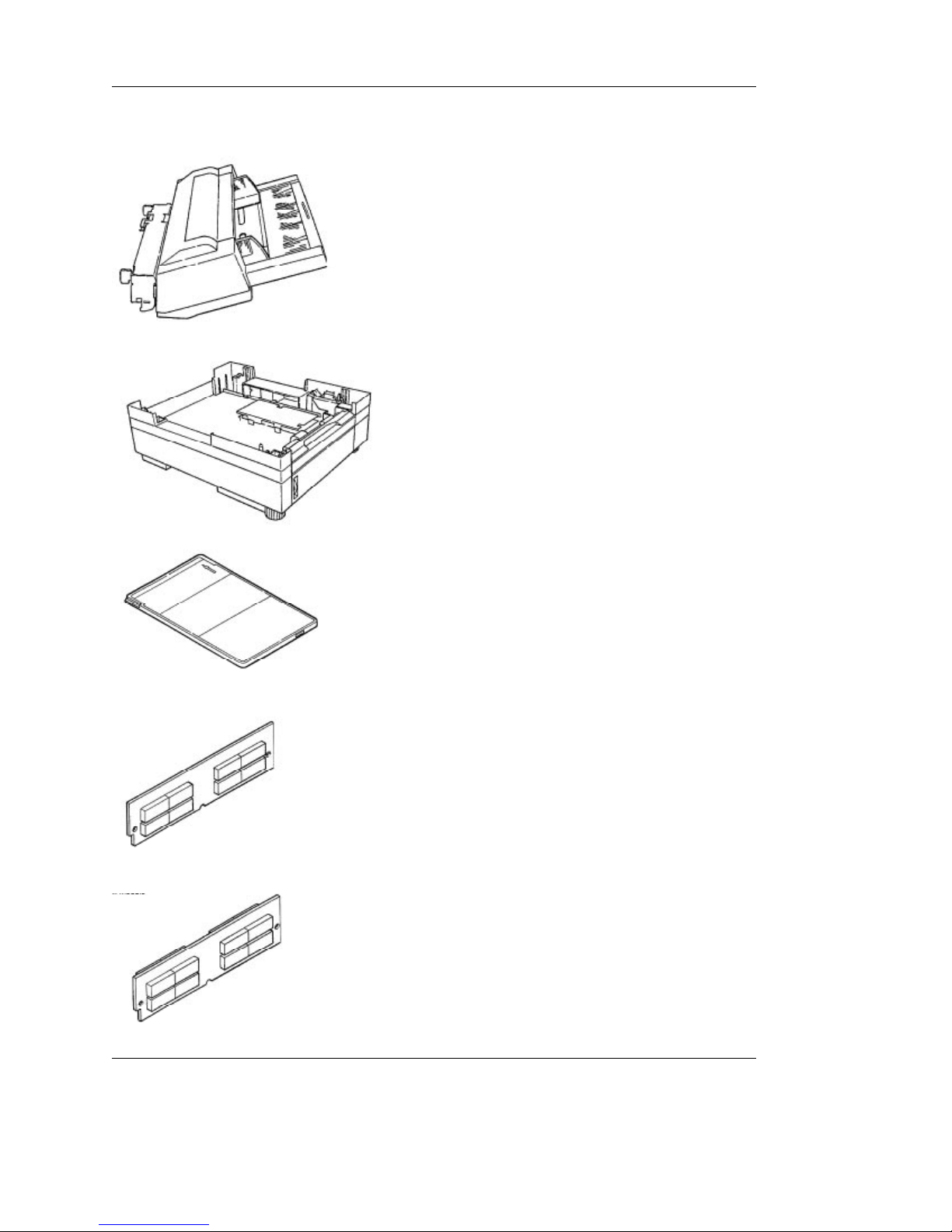
1.3 Optional Configuration
The options below are available for use with OL1200. They are sold separately from the printer unit.
(1) Power Envelope Feeder
(2) High Capacity Second Paper Feeder
(3) Font Card
(4) RAM module
• 8MB RAM module
• 16MB RAM module

%1.4 Specification
1.4 Specification
(1) Type Desk top
(2) External dimensions Height 10.6 (270 mm) (excludes protruding Width 14.4 (366 mm) Portion)
Depth 16.9 (430 mm)
(3) Weight 15.2 kg (33.5 lbs)
(4) Development method Dry electrophotography Exposure method LED stationary head
(5) Paper used <Type>
• Standard paper Xerox 4200 (20 lbs)
• Application paper (manual face-up feed) Label Envelope OHP paper (Transparency)
<Size>
• Standard sizes Letter Legal Executive Envelope A4 A5 B5 A6
• Applicable sizes Width: 3.4 to 8.5 (86 to 228 mm) Length: 5.5 to 14 (140 to 355.6
mm) <Thickness> Automatic feed: 16 to 28 lbs (60 to 105 g/m 2 ) Manual feed:
Label, OHP paper (transparency) Envelope
(6) Printing speed
First print: 12 sec.
Continuous print: 12 sheets/min.
Warm-up time: 90 sec. [at room temperature 77°F (25°C) and rated voltage (120 VAC)]
(7) Paper feed method Automatic feed or manual feed
(8) Paper delivery method Face down/face up
(9) Resolution 600 x 600 dots/inch
(10) Power input 120 VAC + 5.5%, 15% (ODA) 230/240 VAC + 10%, 14% (ODA/OEL)
(11) Power consumption
Peak: Approx. 600W
Typical Operation: Approx. 220W
Idle: Approx. 100W
Power save mode: Approx. 20W
(12) Temperature and humidity During operation: 50 to 90°F (10 to 32°C) In storage: 14 to 110°F
(10 to 43°C)
(13) Noise During operation: 50 dB (A) or less At standby: 45 dB (A) or less Power save mode: 43
dB (A) or less
(14) Consumables Toner cartridge kit 5,000 (5% duty) Image drum cartridge 30,000 (at continuous
printing) 20,000 (3 page/job) 15,000 (1 page/job)
%1.5 Safety Standards
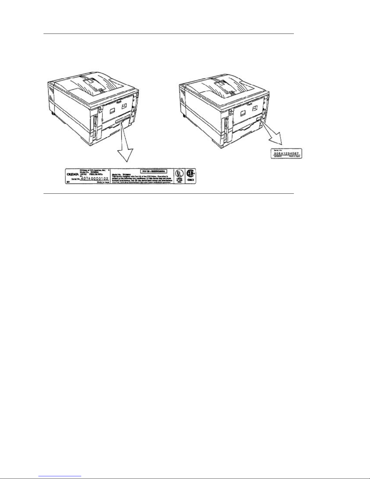
1.5 Safety Standards
1.5.1 Certification label
The safety certification label is affixed to the printer in the position below.
%1.5.2 Warning Label
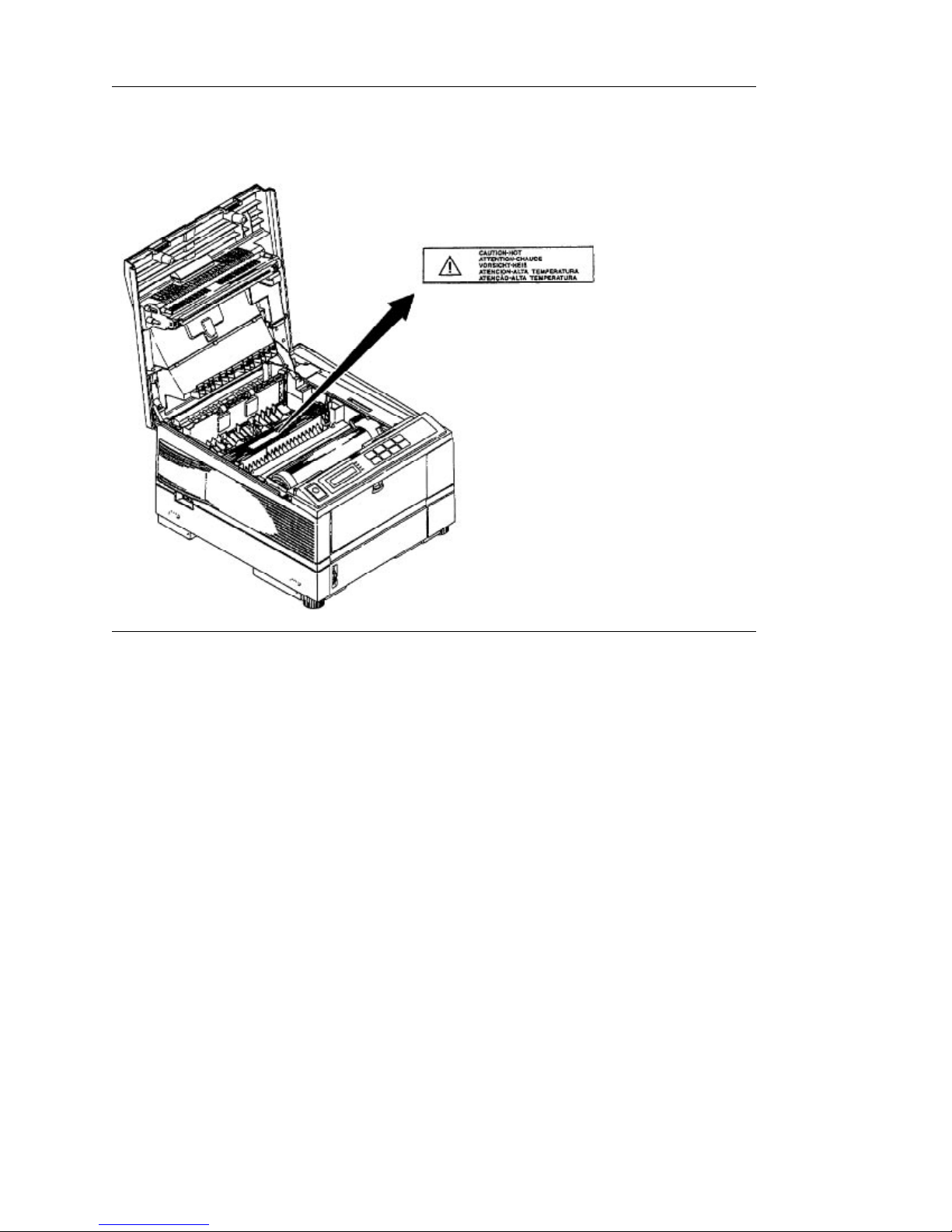
1.5.2 Warning label
The warning label is affixed to the portion which may cause an injury to human body. Follow the
instructions on warning labels during maintenance.

Chapter 2
%2. Operation Description
2. OPERATION DESCRIPTION
OL1200 consists of a control board, a power supply/sensor board, a driver board, an operator panel and
an electro-photographic process mechanism.
The control board receives data through a host I/F, decodes and edits the data, and stores the edited
data in a memory. After completing edition of one page of data, it references the font memory and
generates bit data on the same memory. At the same time, it transfers the bit image data to an LED head
in units of one dot line.
The electro-photographic process mechanism prints data on paper.
The operator panel is used for operations and status display.
Fig. 2-1 shows an OL1200 block diagram.
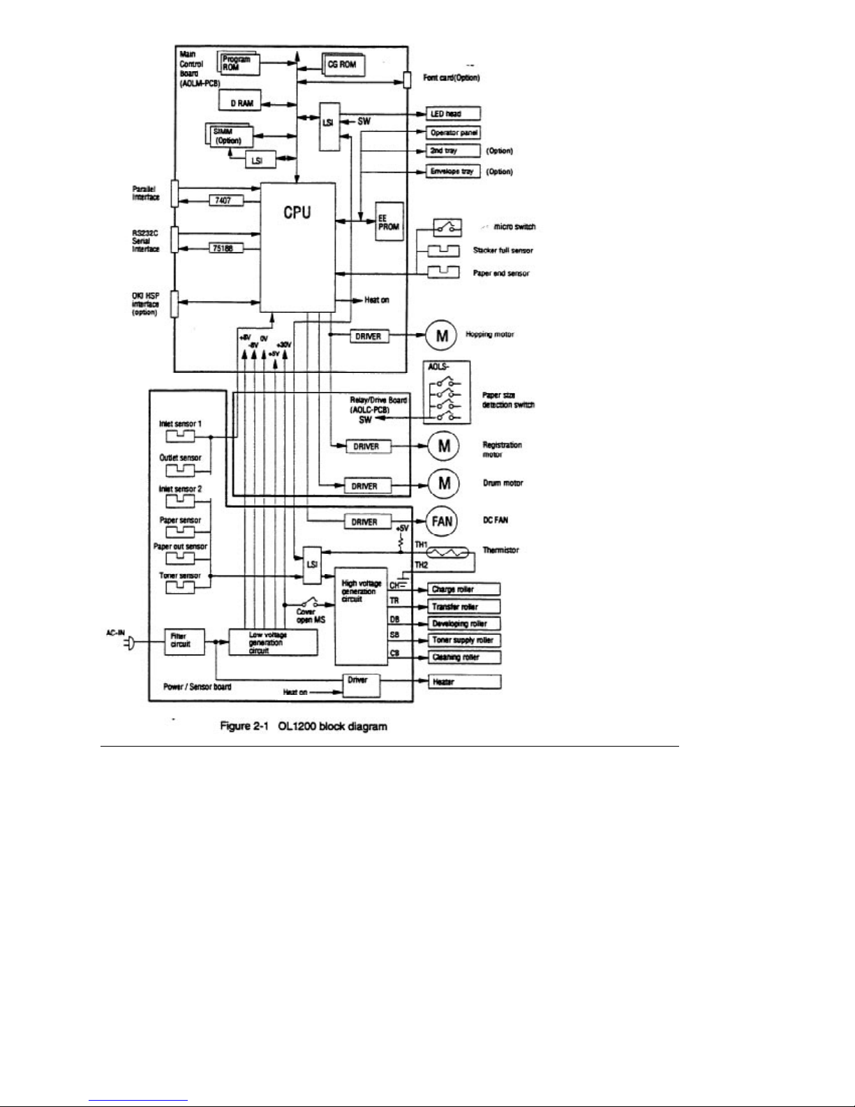

%2.1 Main Control Board (Aolm-Pcb)
2.1 Main Control Board (AOLM-PCB)
The control board consists of a one chip CPU, LSIs, a program/font ROM, a DRAM, an EEPROM, a host
interface circuit, and a mechanism driving circuit.
(1) One-chip CPU
The one-chip CPU is a custom CPU (32-bit internal bus, 32-bit external bus, 33-MHz clock) that
incorporates a RISC CPU and its peripheral devices, and has the following functions:
Built-in device Function
Chip select controller
Bus controller DRAM controller
DMA controller Transfer of image data from DRAM to OST
Parallel interface controller Control of Centronics parallel interface
Serial interface controller Control of RS-232C serial interface
Timer Generation of various control timing
Serial I/O port Control of operator panel, EEPROM, and
I/O port Inputting/outputting of sensor, signal and
Option I/O interface Control of OKI HSP interface
(2) Program/font ROM
The program/font ROM stores the equipment program and various types of fonts. EPROM/ OTP or
masked ROM is used as an program/font ROM.
(3) Memory
2-Megabyte DRAM (512K x 4) is mounted as resident memory to be used for storing the program and
providing various buffers. This DRAM is expandable up to 34 Mbytes by adding expansion memory
(SIMMs). This DRAM provides the areas shown in the following table.
Control of ROM, DRAM and I/O device
LSI
Monitoring of paper running and paper size
options
motor signal
Memory area Use MENU Expansion RAM
System area Working area used for the
program
Raster buffer Stores converted bit image data Enable Expandable
Receive buffer Stores temporarily the data
received from the host interface
Memory capacity setting
Fixed
Working area
used for the
program
Enable Expandable
Fixed

Page buffer Adds print information to the
Expandable
analyzed receive data and stores
the resulted data.
DLL/macro buffer Stores soft fonts and macro data. Expandable
Font cache buffer Stores bit map fonts generated by
Enable Expandable
the font rasterizer based on
scalable font information
(4) EEPROM
The EEPROM has a 4-kbit capacity and stores the following data.
• Menu data
• Various counter data (page counter, drum counter, fuser counter, etc.)
• Adjustment parameters (LED head drive time, print start position, etc.)
(5) LSI (MSM10S0050-015GS)
This LSI is connected to the CPU via the bus as a peripheral device of the CPU and controls the memory
based on the RAS signal and address signal received from the CPU.
(6) LSI (MBCE31701-040FP-BND)
This LSI is used as a peripheral device of the CPU and performs smoothing compensation (OST) of print
image data (300 dpi and 600 dpi). In addition, it transfers serially bit image data for each dot line to the
LED head.
(7) Host interface
This printer has the following interfaces to the host.
• Centronics bidirectional parallel interface
• RS232C serial interface
• OKI HSP interface (Option)
The single effective interface or the automatic interface select mode can be selected using the menu. If
the busy state of the printer continues for a long time period, the buffer near-full control releases the busy
status at constant intervals even if the host side is busy so not to cause the interface time-out at the host
side.
(a) Centronics bidirectional parallel interface
This is an interface conforming to IEEE-1284 and provides either unidirectional or bidirectional
communications according to each of the following communication modes.
• Compatibility mode
Unidirectional communications from the host to the printer.
• Nibble mode
This mode transmits 4-bit wide data from the printer to the host. In this mode, each 1-byte data is
transferred in the form of two nibbles using ERROR, BUSY, FAULT, and SELECT signal leads. This
mode can provide the bidirectional operation in combination with the compatibility mode.
• ECP mode
his mode provides the asynchronous bidirectional interface and transmits and receives 1-byte data
using eight data signal leads under the semi-duplex control by the host.
When the power is turned on, the compatibility mode is automatically selected. The change to another
mode from the compatibility mode is made through negotiation. (When the BI DIRECTION is set to
ENABLE in the menu, this change can be performed.) (For the electrical/physical characteristics of this
interface, see APPENDIX B)
(b) RS232C serial interface
The following protocol is supported for the serial interface conforming to EIA RS232C.
• READY/BUSY (DTR HI or DTR LO)
• X-ON/X-OFF
• RBST X-ON
(For the electrical/physical characteristics of the interface, see APPENDIX A)
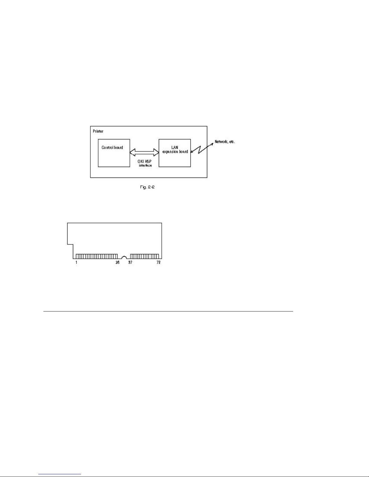
(c) OKI HSP interface (Option)
This interface (slot) is an OKI unique universal interface that provides the platform to connect various
boards (including those supplied by third venders) such as the LAN connection expansion board.
Any expansion boards compatible with this interface can be mounted on the Control board without
modifying the program at the printer side. The conceptual diagram of the OKI HSP interface is shown in
Fig. 2-2.
(For the electrical/physical characteristics of the OKI HSP interface, see the OKI HSP interface technical
manual. This manual will not be available to the general public.)
(8) RAM module
• Pin layout
• Basic specificaton
- Type: 72 pins SIIM (32 bits buss width)
- Access time: 60ns, 70ns, 80ns, 100ns
- Capacity: 1, 2, 4, 8, or 16MB (16 MB RAM will not be sold by Okidata)
- Parity: None

%2.2 Power/Sensor Board
2.2 Power/Sensor Board
The power/sensor board consists of an AC filter circuit, a low voltage power supply circuit, a high voltage
power supply circuit, heater drive circuit, and photosensors.
(1) Low voltage power supply circuit
This circuit generates the following voltages.
Output voltage Use
+5 V Logic circuit supply voltage +30 V
Motor and fan drive voltage and source voltage for
high-voltage supply
RS-232C line voltage 8 V
RS-232C line voltage and analog circuit supply
voltage
(2) High voltage power supply circuit
This circuit generates the following voltages necessary for electro-photographic processing from
+30 V according to the control sequence from the control board. When cover open state is
detected, +30 V supply is automatically interrupted to stop the supply of all the high-voltage
outputs.
Output Voltage Use Remarks
CH -1.30 KV Voltage applied to
charging roller
DB -240 V/+300 V Voltage applied to
developing roller
SB -360 V/450 V Voltage applied to
toner supply roller
+8 V
TR +4 KV/-1.3 kV Voltage applied to
transfer roller
CB +400 V Voltage applied to
cleaning roller
(3) Photosensor
The photosensor mounted on this power/sensor board supervises the paper running state during printing.
Figure 2-3 shows the sensor layout diagram.
Variable
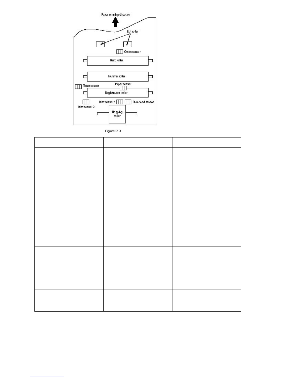
Sensor Function Sensing state
Inlet sensor 1 Detects the leading part of the
paper and gives the
ON: Paper exists.
OFF: No paper exists.
supervision timing for
switching from hopping
operation to feeding
opera-tion. Supervises the
paper running state and the
paper size accord-ing to the
paper reach time and running
time.
Inlet sensor 2 Detects the form width. ON: A4 or larger
OFF: Smaller than A4
Paper sensor Detects the leading part of the
paper. Supervises the paper
ON: Paper exists.
OFF: No paper exists.
running state.
Outlet sensor Supervises the paper feed
and size according to the time
ON: Paper exists.
OFF: No paper exists.
of arrival to the sensor and
the time of passage of paper.
Paper end sensor Detect the end of the paper. ON: Paper exists.
OFF: No paper exists.
Toner low sensor Detects the lack of toner. ON long: Toner low exists
OFF short: No Toner low
exists

%2.3 Relay/Driver Board (Aolc Board)
2.3 Relay/Driver Board (AOLC board)
This board relays signals between the Control board and the Power/Sensor board and includes the
registration motor and drum motor driver IC.
%2.4 Electro-Photographic Process
2.4 Electro-photographic Process
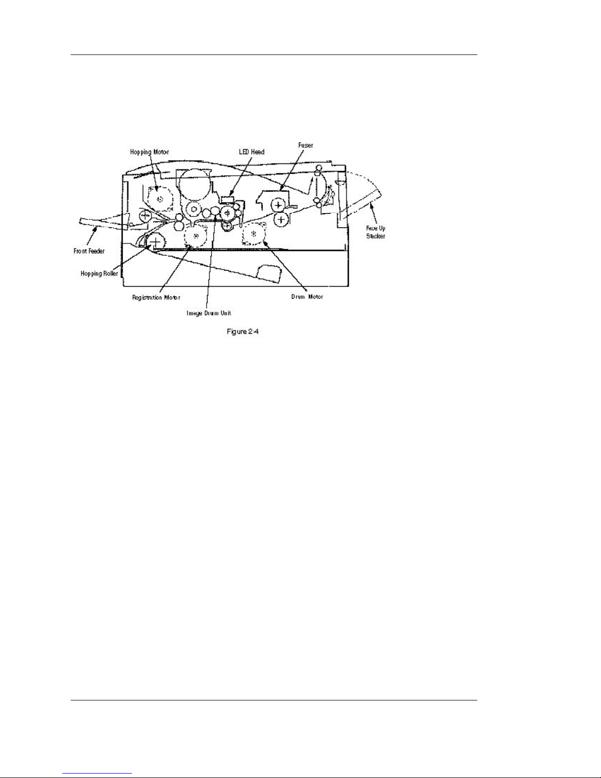
2.4.1 Electro-photographic process mechanism
This mechanism prints image data from the control board on the paper by electro-photographic process.
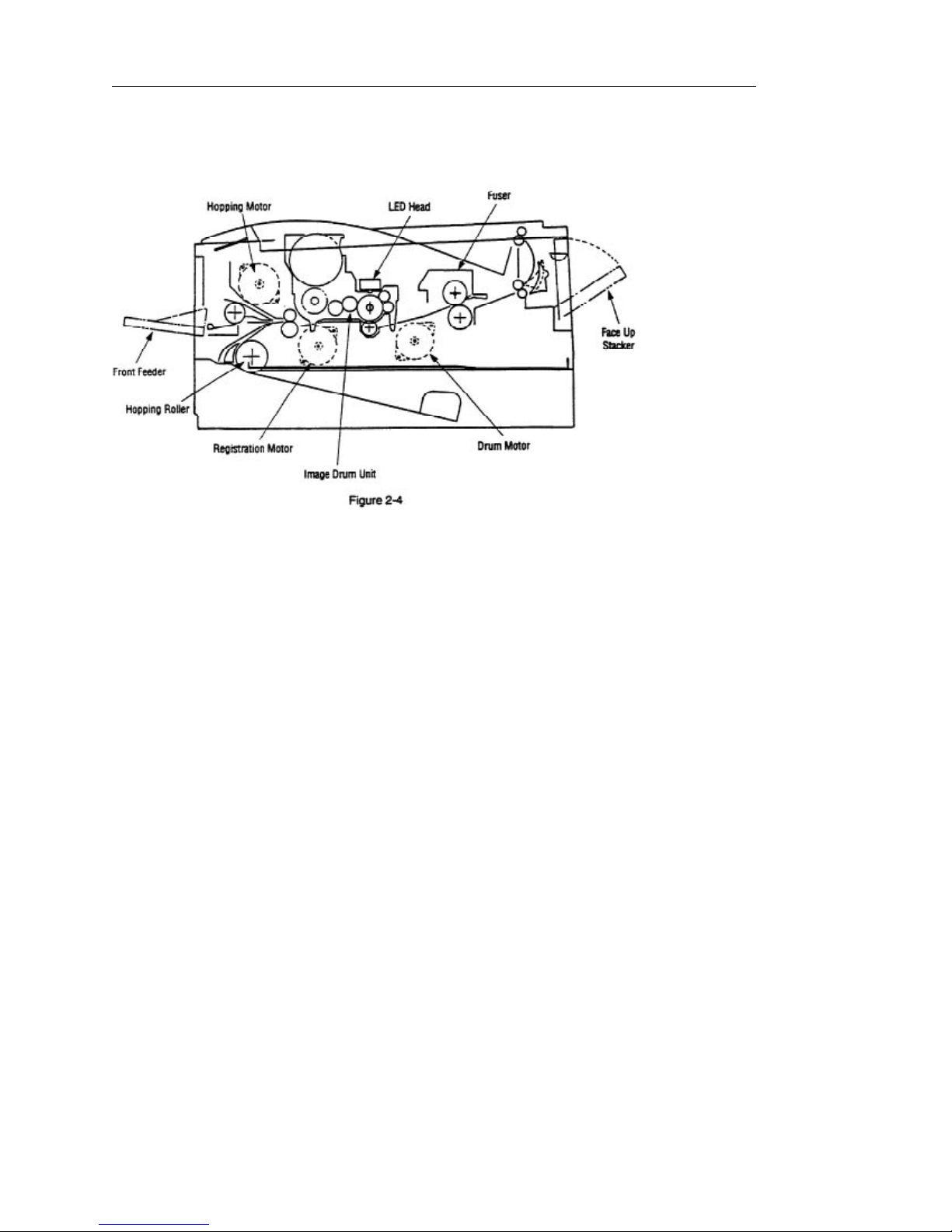
The Figure 2-4 shows the layout of the electro-photographic process mechanism.
(1) Image drum unit
The image drum unit consists of a sensitive drum, a charger, and a developer. The unit forms a
toner image on the sensitive drum, using a electrostatic latent image formed by the LED head.
(2) Hopping motor
This motor is a pulse motor of 48 steps/rotation that is two-phase excited by the signal from the
control board. It drives the hopping roller of the first tray and the front feed roller via two one-way
clutches according to the direction of rotation.
(3) Registration motor
This motor is a pulse motor of 48 steps/rotation that is two-phase excited by the signal from the
control board. It drives the registration roller.
(4) Drum motor
This drum motor is a pulse motor of 48 steps/rotation that is two-phase excited by the signal from
the control board and is the main motor of this mechanism.
(5) LED head
Image data for each dot line from the control board is received by the shift register and latch
register. The 5120 LEDs are driven to radiate the image data to the image drum.
(6) Fuser
The fuser consists of a heater, a heat roller, a thermistor and a thermostat. An AC voltage from the
power supply board is applied to the heater under the control of the HEATON signal from the
control board. This AC voltage heats the heater. The control board supervises the heat roller
temperature via the thermistor, and regulates the heater roller at a predetermined temperature
(185 ~ 188°C) by connecting or disconnecting the AC voltage supply to the heater. If the heater
roller temperature rises abnormally, the thermostat of the heater voltage supply circuit is activated
to cut the AC voltage supply forcibly.

%2.4.2 Electro-Photographic Process
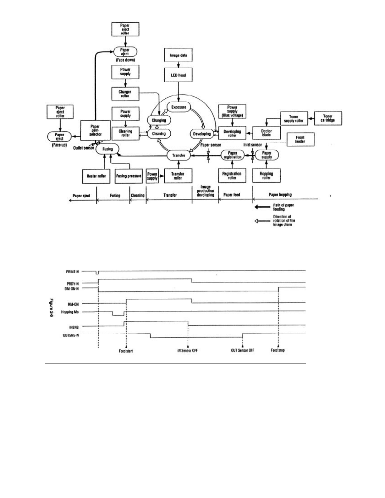
2.4.2 Electro-photographic process
The electro-photographic processing is outlined below. Figure 2-5 shows the electro-photo-graphic
printing process.
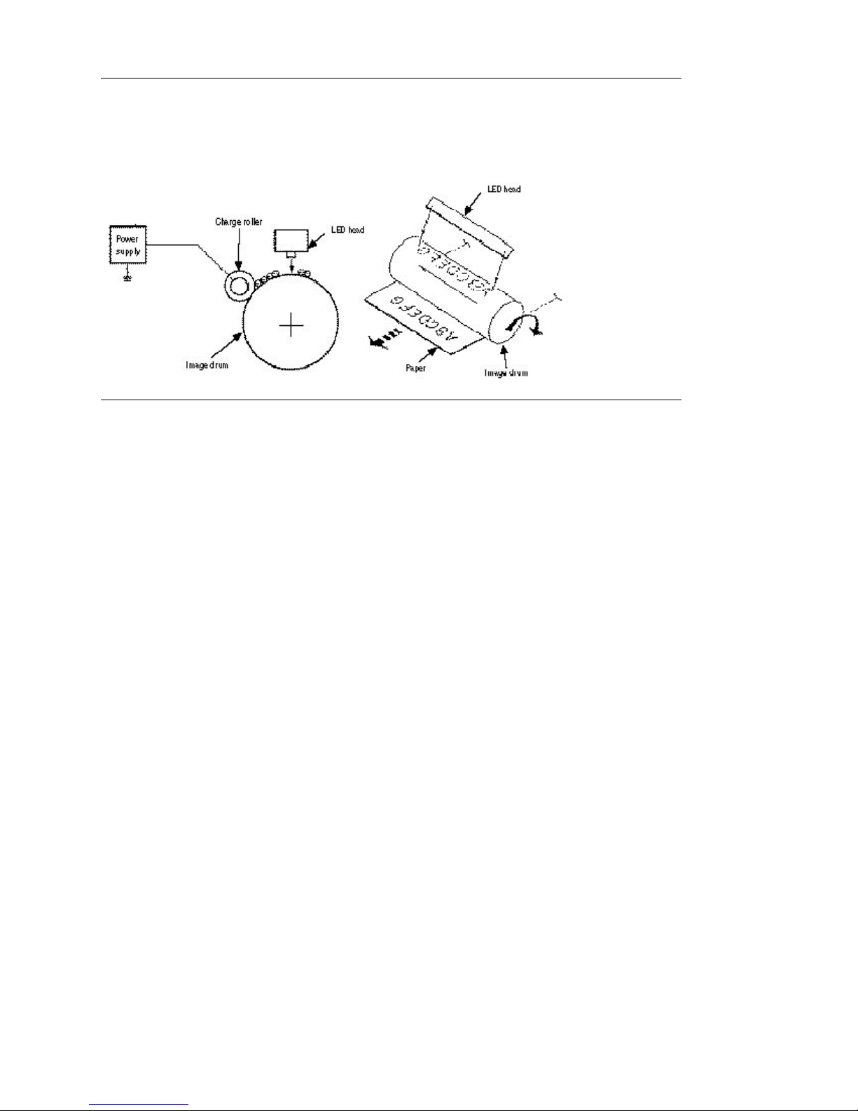
1 Charging
The surface of the image drum is uniformly charged with negative charges by applying a negative
voltage to the charge roller.
2 Exposure
Light emitted from the LED head irradiates the negatively charged surface of the image drum. The
surface potential of the irradiated part of the image drum surface is lowered, so that an
electrostatic latent image associated with the print image is formed.
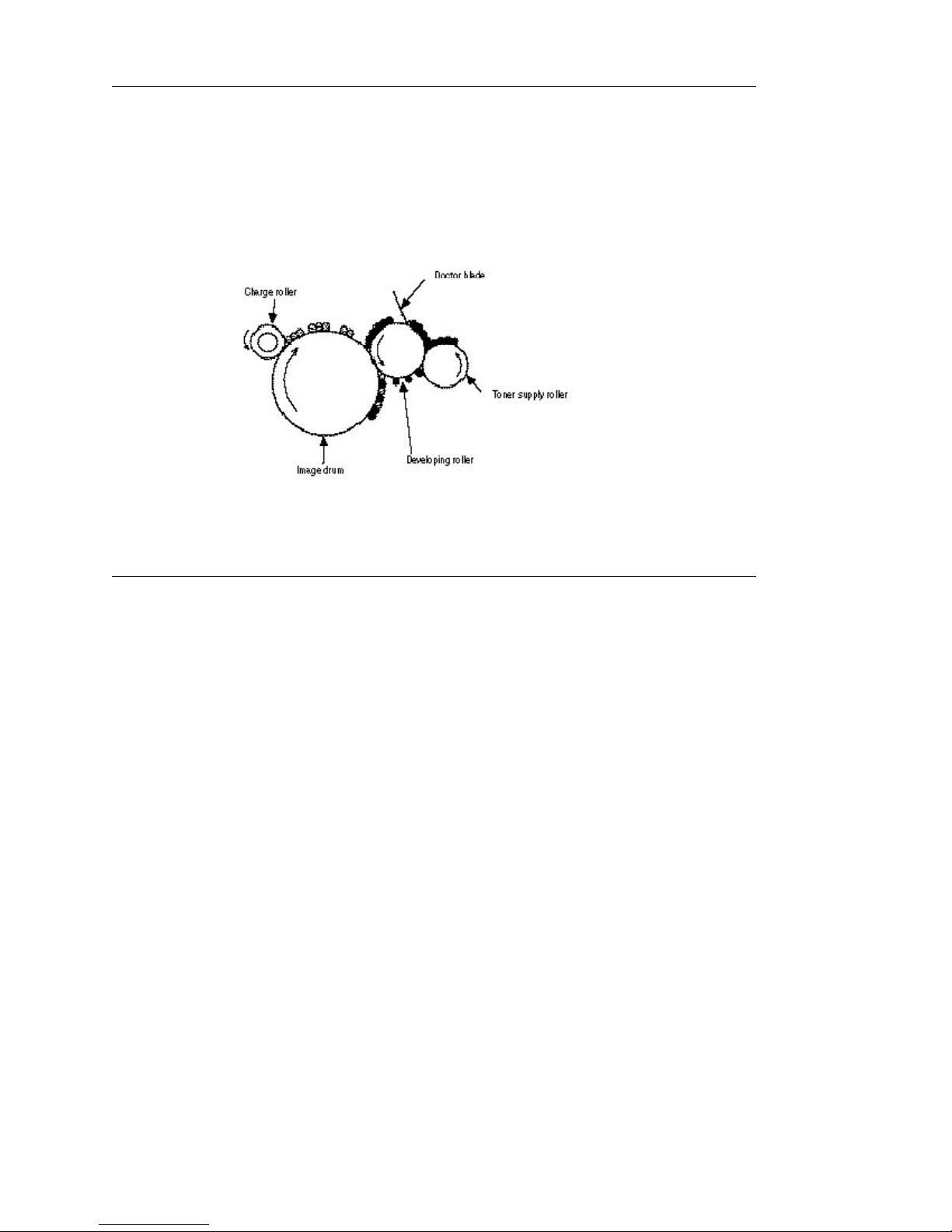
3 Developing and toner recovery
When the negatively charged toner is brought into contact with the image drum, it is attracted to the
electrostatic latent image by static electricity, making the image visible. At the same time, the
residual toner on the image drum is attracted to the developing roller by static electricity.
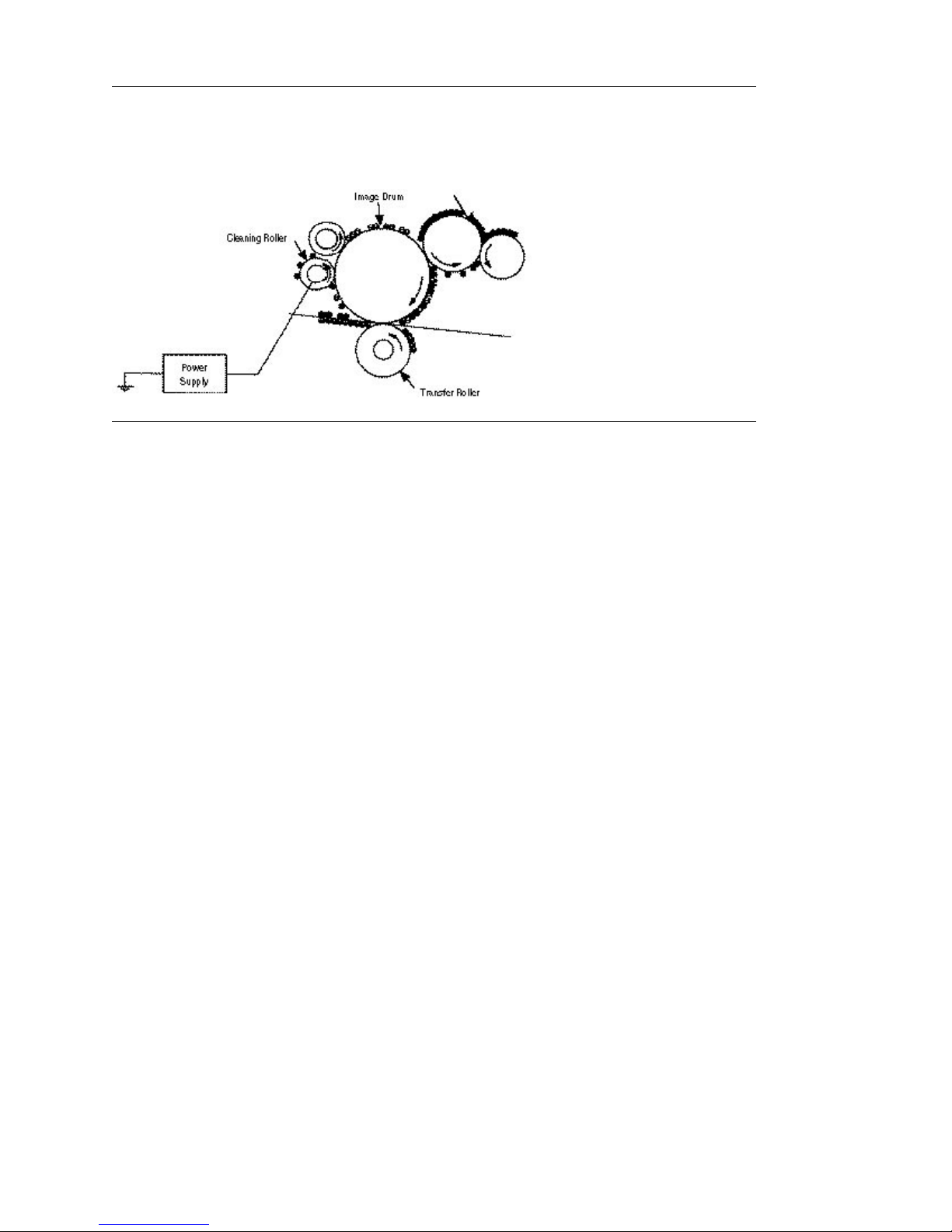
4 Transfer
When paper is placed over the image drum surface and a positive charge, opposite in polarity to the
toner, is applied to the reverse side of the paper from the transfer roller, the toner is attracted by
the positive charge and is transferred to the paper. As a result, the toner image formed on the
image drum is transferred to the paper.
5 Temporary cleaning
Residual toner that remains on the image drum without being transferred is made uniform by the
cleaning roller and is temporarily attracted to the cleaning roller by static electricity.
6 Fusing
The toner image transferred to the paper is fused under heat and pressure. Figure 2-6 shows an
electro-photographc process timing chart.
%2.4.3 Process Operation Descriptions
2.4.3 Process operation descriptions
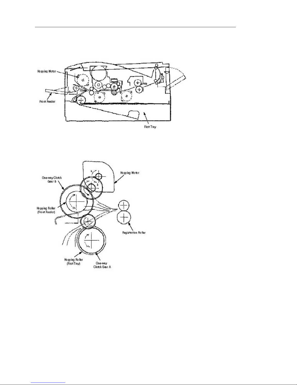
(1) Hopping
Hopping from the first tray and the front feeder are effected by a single hopping motor in the
mechanism shown below.
Turning the Hopping motor in the a direction drives the hopping roller of the first tray. Turning the Hopping
motor in the b direction drives the Hopping roller of the front feeder. The both and hopping gears contain
one-way bearing, so that turning each of these gears in reverse direction will not be transmitted to the
corresponding roller.
(a) Hopping (1st tray)
1 Rotating the pulse motor in the direction a (Clock-wise direction) drives the hopping roller of the
first tray to advance the paper until the inlet sensor turns on. At the same time, the one-way
clutch gear B also rotates. However, the hopping roller of the front feeder will not rotate due to the
one-way bearing.
2 After turning on the inlet sensor, the paper advances further by a predetermined length until it hits
the registration roller. (The skew of the paper can thus be corrected.)
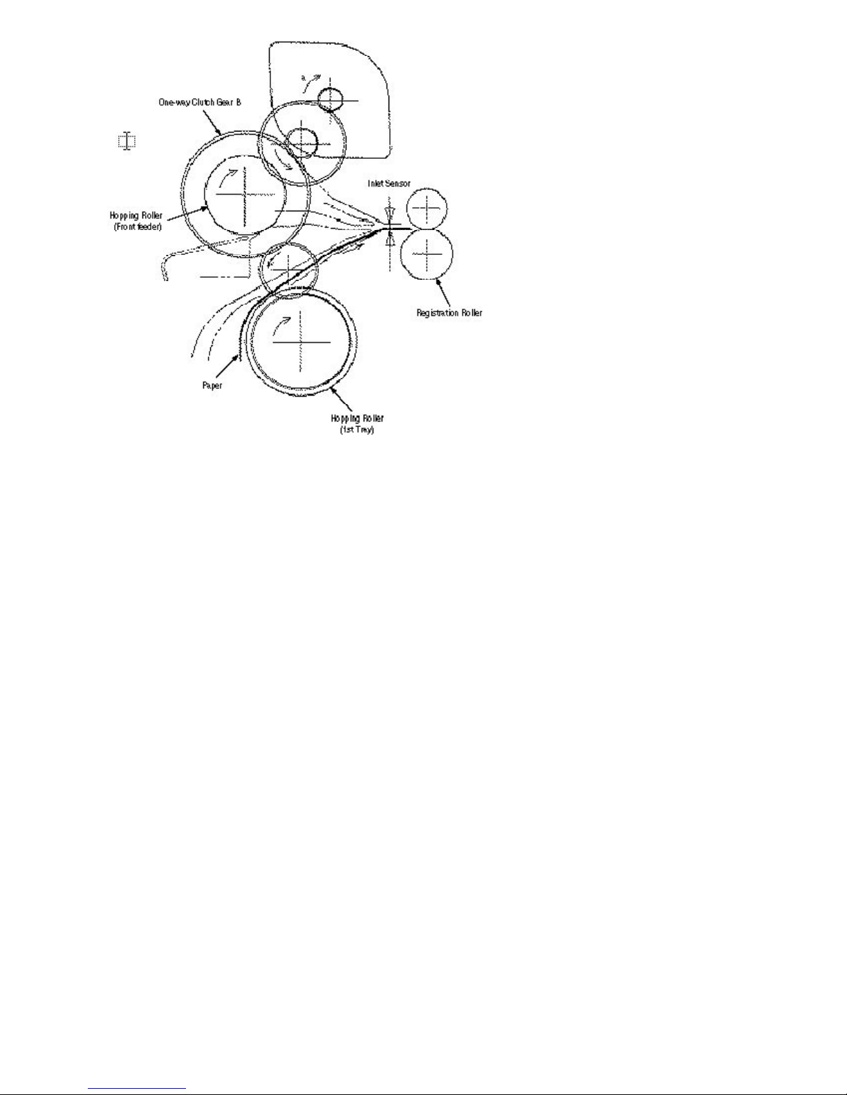
(b) Hopping (front feeder)
1 Rotating the pulse motor in the direction b (Counter Clock-wise direction) drives the hopping roller
of the front feeder to advance the paper until the inlet sensor turns on. At the same time, the
one-way clutch gear A also rotates. However, the hopping roller of the 1st tray will not rotate due
to the one-way bearing.
A cam to push down the front feeder plate is attached on each of the ends of the hopping roller
shaft. These cams push down the front feeder plate when the hopping operation is not performed
so as to facilitate the setting of paper into the tray. A microswitch is provided under the front
feeder plate to detect that the front feeder plate is at the lower position. When the front feeder
plate is at the lower position, this microswitch causes the motor to stop.

2 After turning on the inlet sensor, the paper advances further by a predetermined length until it hits
the registration roller. (The skew of the paper can thus be corrected.)

%(2) Feeding
(2) Feeding
After the end of hopping, the pulse motor drives the registration roller. The registration roller
advances the paper until it comes out of the registration roller.
When leading edge of the paper causes the paper sensor to turn on, the printing is started
synchronously.

%(3) Charging
(3) Charging
Charging is effected by applying a DC minus voltage to the charge roller that is in contact with the image
drum surface.
%(4) Exposure
(4) Exposure
Light emitted from the LED head irradiates the image drum surface with negative charges. The surface
potential of the irradiated part of the image drum drops, thereby forming an electrostatic latent image
associated with the image signal.
%(5) Developing
(5) Developing
Toner is attracted to the electrostatic latent image on the image drum surface to convert it into a
visible toner image. Developing takes place at the contact between the image drum and the
developing roller.
1 As the toner supply roller rotates while rubbing on the developing roller, a friction charge is
generated between the developing roller and the toner, allowing the toner to be attracted to the
developing roller. (The developing roller surface is charged positive and the toner, negative.)
2 The toner attracted to the developing roller is scraped off by the doctor blade, forming a thin coat
of toner on the developing roller surface.
3 Toner is attracted to the exposed part (low-potential part) of the image drum at the contact
between the image drum and the developing roller, making the electrostatic latent image visible.

%(6) Transfer
(6) Transfer
The transfer roller is composed of conductive sponge material and is designed to make the image
drum surface and the paper closely into contact.
Paper is placed over the image drum surface, and a positive charge, opposite in polarity to the
toner, is applied to the paper from its reverse side.
The application of a high positive voltage from the power supply to the transfer roller causes the
positive charge induced to the transfer roller surface to be transferred to the paper at the contact
between the transfer roller and the paper. As a results, toner charged negative that is attracted to
the image drum surface is transferred to the upper side of the paper by the positive charge on the
lower side of the paper.

%(7) Fusing
(7) Fusing
After the end of the transfer, the unfused toner image is fused on the paper under heat and
pressure as it passes between the heater roller and the back-up roller. The heater roller with a
Teflon coating incorporates a 400W heater (Halogen lamp), which heats the heat roller.
A thermistor which is in contact with the heater roller regulates the heater roller at a predetermined
temperature (about 185 ~ 188°C). A safety thermostat cuts off voltage supply to the heater by
opening the thermostat in the event of abnormal temperature rises.
The back-up roller is held under a pressure of 2.5 kg from the pressure spring at each side.
%(8) Cleaning
(8) Cleaning
After the end of the transfer, residual toner on the image drum is attracted to the cleaning roller
temporarily by static electricity to clean the image drum surface.

%(9) Cleaning Of Rollers
(9) Cleaning of rollers
The charge roller, transfer roller and cleaning roller are cleaned in the following cases:
• In warming up at power-on time
• In warming up after the cover is opened and closed
• When the number of accumulated sheets is 10 or more and the printout operation ends
Changes in bias voltage applied to each roller move adhesive toner from the roller to the image
drum and return it to the developer.

%2.5 Paper Jam Detection
2.5 Paper Jam Detection
The paper jam detection function supervises the paper state at power-on time and during printing. In the
event that a jam occurs, this function interrupts the printing process. If any of the following errors is
presented, recovery printing will be performed by removing the jammed paper ( by opening the upper
cover, removing the jammed paper and closing the upper cover).
Error Cause of error
Paper input jam • At power-on time, the paper is placed at the inlet sensor.
• After hopping operation is attempted three times, the leading part of
the paper does not reach the inlet sensor.
Paper feed jam • At power-on time, the paper is placed at the paper sensor.
• The leading part of the paper does not reach the paper sensor within
a predetermined distance after the paper has reached the inlet sensor.
• The trailing part of the paper does not pass over the paper sensor
within a predetermined distance after the leading edge of the paper
has passed over the paper sensor.
• The leading part of paper does not reach the outlet sensor within a
predetermined distance after the paper has reached the paper sensor.
Paper exit jam • At power-on time, the paper is placed on the outlet sensor.
• The paper does not pass over the outlet sensor within a
predetermined time after the leading part of the paper has reached the
outlet sensor.
• The paper size check with the manual feed specified considers the
reference size as free size.
Paper size error Paper size error
• The size of the paper is supervised by the inlet sensor
1. It is detected that the paper does not pass over the inlet sensor 1
within predetermined range of distance.
• The inlet sensor 2 detects that the size of the loaded paper is A4 or
larger, or smaller than A4. The detected paper size differs from the
paper size set by command or menu.
• The paper size check with the manual feed specified considers the
reference size as free size.
 Loading...