

Okidata OKIPAGE 6e, OKIPAGE 6ex Service Manual

Thank You for purchasing this
Click Here for more Factory Service
Manuals for other Computer and
Printer / Copier Manufacturers
from PCTECHINFO!

OKIPAGE 6e/6ex
LED PAGE PRINTER
Service Manual
All specifications are subject to change without notice.
P/N 59276401

HP and LaserJet are registered trademarks of Hewlett-Packard Company.
Adobe and PostScript are trademarks of Adobe Systems Incorporated, which may be registered in
certain jurisdictions.
LocalTalk is a registered trademark of Apple Computer Inc.
Centronics is a registered trademark of Centronics Data Corporation.
OKIDATA is a registered trademark of Oki America, Inc.
OKIDATA est une marque déposée de Oki America, Inc.

Contents
1. CONFIGURATION...........................................................................................................1 - 1
1.1 System Configuration .............................................................................................. 1 - 1
1.2 Printer Configuration...............................................................................................1 - 2
1.3 Optional Configuration............................................................................................ 1 - 3
1.4 Specification ............................................................................................................1 - 5
1.5 Safety Standards ...................................................................................................... 1 - 7
1.5.1 Certification Label.......................................................................................1 - 7
1.5.2 Warning Label .............................................................................................1 - 8
1.5.3 Warning/Caution Marking ........................................................................... 1 - 9
2. OPERATION DESCRIPTION ........................................................................................2 - 1
OVERVIEW ........................................................................................................................ 2 - 1
OKIPAGE 6e Block Diagram (Figure 2-1) ........................................................................ 2 - 2
OKIPAGE 6ex Block Diagram (Figure 2-2) ....................................................................... 2 - 3
2.1 Control Board .......................................................................................................... 2 - 4
Single Chip CPU .........................................................................................2 - 4
Program and Font ROM .............................................................................. 2 - 4
DRAM ..................................................................................................................... 2 - 5
EEPROM ................................................................................................................. 2 - 5
Parallel Interface...................................................................................................... 2 - 5
2.2 PS Board (Option) ................................................................................................... 2 - 6
2.3 RAM Board (OKIPAGE 6e/6ex option)..................................................................2 - 7
DRAM ......................................................................................................... 2 - 7
SIMM Socket...............................................................................................2 - 7
RAM Board Block Diagram (Figure 2-4) ............................................................... 2 - 7
2.4 Power Supply Board................................................................................................2 - 8
Low Voltage Power Supply Circuit ............................................................. 2 - 8
High Voltage Power Supply Circuit ............................................................ 2 - 8
Photosensor..................................................................................................2 - 8
Sensor Layout Diagram (Figure 2-3).......................................................................2 - 9
Sensor Functions and StatusTable (Figure 2-5)....................................................... 2 - 9
2.5 Electrophotographic Process ................................................................................. 2 - 10
2.5.1 Electrophotographic Process Mechanism..................................................2 - 10
Electrophotographic Process Mechanism (Figure 2-6) ............................. 2 - 11
Image Drum Unit....................................................................................... 2 - 12
Registration Motor....................................................................................2 - 12
Drum Motor...............................................................................................2 - 12
LED Head .................................................................................................. 2 - 12
Fuser ..........................................................................................................2 - 12
Table of Contents TOC - 1 OKIPAGE 6e/6ex
Service Manual, P/N 59276401

2.5.2 Electrophotographic Process ..................................................................... 2 - 13
Charging .................................................................................................... 2 - 13
Exposure ....................................................................................................2 - 13
Developing and Toner Recovery ............................................................... 2 - 13
Transfer......................................................................................................2 - 13
Temporary Cleaning .................................................................................. 2 - 13
Fusing ........................................................................................................ 2 - 13
Electrophotographic Printing Process Diagram (Figure 2-7) .................... 2 - 14
Electrophotographic Process Timing Chart (Figure 2-8) .......................... 2 - 15
2.5.3 Process Operation Descriptions................................................................. 2 - 16
Hopping and Feeding ................................................................................ 2 - 16
Hopping ..................................................................................................... 2 - 17
Feeding ......................................................................................................2 - 18
Charging .................................................................................................... 2 - 19
Exposure ....................................................................................................2 - 20
Developing ................................................................................................ 2 - 22
Transfer......................................................................................................2 - 24
Fusing 2 - 25
Cleaning..................................................................................................... 2 - 26
Cleaning of rollers ..................................................................................... 2 - 26
2.6 Paper Jam Detection ..............................................................................................2 - 27
Paper Feed Timing Chart.......................................................................................2 - 28
Paper Feed Check List...........................................................................................2 - 29
Paper Length List .................................................................................................. 2 - 29
2.7 Cover Open............................................................................................................ 2 - 30
Operation during Toner Low state.............................................................2 - 31
2.8 Toner Low Detection ............................................................................................. 2 - 31
Device........................................................................................................2 - 31
Operation ................................................................................................... 2 - 31
Operation during Toner Full state.............................................................. 2 - 31
TONER LOW State Diagram.................................................................... 2 - 32
TONER FULL StateDiagram....................................................................2 - 32
3. PARTS REPLACEMENT ................................................................................................ 3 - 1
3.1 Precautions for Parts Replacement .......................................................................... 3 - 1
3.2 Parts Layout.............................................................................................................3 - 3
3.3 How to Change Parts ...............................................................................................3 - 6
3.3.1 Upper Cover ................................................................................................3 - 7
3.3.2 Stacker ......................................................................................................... 3 - 8
3.3.3 LED Head .................................................................................................... 3 - 9
3.3.4 Eject Roller Assy ....................................................................................... 3 - 10
3.3.5 Pulse Motor (Main) ................................................................................... 3 - 11
3.3.6 Pulse Motor (Registration) ........................................................................ 3 - 12
3.3.7 Lower Base Unit........................................................................................3 - 13
3.3.8 Motor Assy ................................................................................................ 3 - 14
3.3.9 Hopping Roller Assy ................................................................................. 3 - 15
3.3.10 Stacker Cover Assy....................................................................................3 - 16
3.3.11 Registration Roller.....................................................................................3 - 17
Table of Contents TOC - 2 OKIPAGE 6e/6ex
Service Manual, P/N 59276401

3.3.12 Transfer Roller...........................................................................................3 - 18
3.3.13 Fusing Unit Assy ....................................................................................... 3 - 19
3.3.14 Back-up Roller...........................................................................................3 - 20
3.3.15 Sensor Plate (Inlet) ....................................................................................3 - 21
3.3.16 Toner Sensor (Adhesion) ........................................................................... 3 - 22
3.3.17 Sensor Plate (Outlet)..................................................................................3 - 23
3.3.18 Manual Feed Guide Assy........................................................................... 3 - 24
3.3.19 Sensor Plate (Paper Supply) ...................................................................... 3 - 25
3.3.20 Main Control PCB ..................................................................................... 3 - 26
3.3.21 Power Supply Board and Contact Assy.....................................................3 - 27
3.3.22 Transformer ............................................................................................... 3 - 28
3.3.23 Cassette Guide L........................................................................................3 - 29
3.3.24 Cassette Guide R .......................................................................................3 - 30
4. ADJUSTMENT..................................................................................................................4 - 1
4.1 Maintenance Utility Program (OKIPAGE 6e).........................................................4 - 1
How to Get the OKIPAGE 6e Maintenance Utility Program...................... 4 - 1
4.2 EEPROM Parameter Values Adjustments (OKIPAGE 6ex) ...................................4 - 2
4.2.1 Maintenance Modes and Functions .............................................................4 - 2
User Maintenance Mode..............................................................................4 - 2
System Maintenance Mode .........................................................................4 - 2
Engine Maintenance Mode..........................................................................4 - 3
4.3 Adjustment When Replacing a Part.........................................................................4 - 4
4.3.1 OKIPAGE6e: 300 dpi LED head.................................................................4 - 4
LED Head Drive Time Setting ....................................................................4 - 4
LED Head Luminous Energy ...................................................................... 4 - 4
LED Head Width Setting.............................................................................4 - 5
LED Head Type Setting............................................................................... 4 - 5
Uploading/Downloading EEPROM data .................................................... 4 - 6
4.3.2 OKIPAGE6ex: 600dpi LED head................................................................4 - 7
Setting of LED Head Drive Time................................................................ 4 - 7
Luminous Intensity Marking Label .............................................................4 - 7
Setting of LED Head Drive Time (OKIPAGE6e) .......................................4 - 8
Luminous Intensity Marking and Drive Time Parameter Table ..................4 - 8
Procedure ..................................................................................................... 4 - 9
Setting of LED Head Drive Time (OKIPAGE 6ex) ..................................4 - 10
Luminous Intensity Marking and Drive Time Parameter Table ................4 - 10
Procedure ................................................................................................... 4 - 11
5. PERIODICAL MAINTENANCE .................................................................................... 5 - 1
5.1 Periodical Replacement Parts ..................................................................................5 - 1
5.2 Cleaning................................................................................................................... 5 - 1
5.2.1 Cleaning of LED Lens Array.......................................................................5 - 1
6. TROUBLESHOOTING PROCEDURES ....................................................................... 6 - 1
6.1 Troubleshooting Tips ............................................................................................... 6 - 1
6.2 Check Points before Correcting Image Problems....................................................6 - 1
6.3 Tips for Correcting Image Problems ....................................................................... 6 - 1
Table of Contents TOC - 3 OKIPAGE 6e/6ex
Service Manual, P/N 59276401

6.4 Preparation for Troubleshooting..............................................................................6 - 2
PC Display (OKIPAGE 6e) .....................................................................................6 - 2
Operator Panel Display (OKIPAGE 6ex) ................................................................ 6 - 2
6.5 Troubleshooting Flowchart......................................................................................6 - 3
6.5.1 Status Message/Trouble List........................................................................ 6 - 3
PC Display Messages (Table 6-1) ............................................................... 6 - 4
LCD Status Messages (Table 6-2) ............................................................. 6 - 11
6.5.2 Status Message Troubleshooting ............................................................... 6 - 24
1-1 The printer does not work normally after the power is turned on. ........... 6 - 25
2-1 Paper Input Jam ........................................................................................6 - 27
2-2 Paper Feed Jam .........................................................................................6 - 28
2-3 Paper Exit Jam .........................................................................................6 - 30
3 Paper size error .........................................................................................6 - 31
4 Fusing Unit Error (ERROR 71) (ERROR 72) (ERROR 73) .................... 6 - 32
5 Fan Error (ERROR 70) ............................................................................ 6 - 33
6.5.3 Image Troubleshooting.............................................................................. 6 - 34
1 Images are Light or Blurred Entirely........................................................6 - 35
2 Dark Background Density ........................................................................6 - 36
3 Blank paper is output. ...............................................................................6 - 36
4 Black Vertical Belts or Stripes .................................................................. 6 - 37
5 Cyclic Error...............................................................................................6 - 38
6 Print Voids................................................................................................. 6 - 39
7 Poor Fusing ............................................................................................... 6 - 40
8 White Vertical Belts or Streaks .................................................................6 - 41
Diagram of Contact Assembly Contact Points (Figure 6-4)..................................6 - 42
Diagram of Power Supply / Transfer Roller Contact Point (Figure 6-5)...............6 - 43
7. WIRING DIAGRAM ....................................................................................................... 7 - 1
7.1 Interconnect Signal Diagram ................................................................................... 7 - 1
OKIPAGE 6e ...........................................................................................................7 - 1
OKIPAGE 6ex .........................................................................................................7 - 2
7.2 PCB Layout and Connector Signal List ..................................................................7 - 3
Control Board .............................................................................................. 7 - 3
Power Supply Board....................................................................................7 - 4
CN1 Pin Assignment (To Fan Motor)...................................................................... 7 - 5
CN2 Pin Assignment (To Drum Motor) ..................................................................7 - 5
CN3 Pin Assignment ............................................................................................... 7 - 6
To Regist motor ....................................................................................................... 7 - 6
Excitation sequence .................................................................................................7 - 6
CN4 Pin Assignment ............................................................................................... 7 - 7
To LED Head (OKIPAGE 6e) .................................................................................7 - 7
HEAD1 & HEAD2 Pin Assignment........................................................................ 7 - 8
To LED Head (OKIPAGE 6ex) ...............................................................................7 - 8
CN6 Pin Assignment ............................................................................................... 7 - 9
To Option feeder ...................................................................................................... 7 - 9
POWER Pin Assignment (To Power Supply/Sensor Board).................................7 - 10
CN8 Pin Assignment (Centronics Parallel) ........................................................... 7 - 11
CN11 Pin Assignment (To Option Board)............................................................. 7 - 12
Table of Contents TOC - 4 OKIPAGE 6e/6ex
Service Manual, P/N 59276401

7.3 Resistance Check...................................................................................................7 - 13
7.4 Short Plug Setting..................................................................................................7 - 15
Main Control Board............................................................................................... 7 - 15
Short Plug Settings ................................................................................................ 7 - 15
Option RAM Board (LQME-PCB) ....................................................................... 7 - 16
SIMM Specification ..............................................................................................7 - 17
Short Plug Setting..................................................................................................7 - 17
Added SIMM / Total Effective RAM Table ..........................................................7 - 17
8. PARTS LIST ...................................................................................................................... 8 - 1
8.1 General Information ................................................................................................8 - 1
Lower Base Unit (Table 8-1) 1 of 2.................................................................................... 8 - 3
Lower Base Unit (Table 8-1) 2 of 2................................................................................... 8 - 5
Upper Cover Unit (Table 8-2) ............................................................................................. 8 - 7
Base Unit (Table 8-3) .......................................................................................................... 8 - 9
Miscellaneous Items .......................................................................................................... 8 - 10
APPENDIX A: CENTRONICS PARALLEL INTERFACE ................................................... A - 1
Connector ........................................................................................................................... A - 1
Cable A - 1
Table of Parallel Interface Signals...................................................................................... A - 2
Signal Level........................................................................................................................ A - 3
Modes A - 3
Data bit length .................................................................................................................... A - 3
Receiving Buffer................................................................................................................. A - 3
Control ................................................................................................................................ A - 3
Interface Circuit.................................................................................................................. A - 3
Timing Charts ..................................................................................................................... A - 4
Interface Parameter Setting (OKIPAGE 6ex)..................................................................... A - 6
APPENDIX B: LOCALTALK (RS422) SERIAL INTERFACE............................................. B - 1
APPENDIX C: DIAGNOSTICS TEST .....................................................................................C - 1
1. Maintenance Modes................................................................................................ C - 1
1.1 User Maintenance Mode......................................................................................... C - 1
Hex Dump .................................................................................................. C - 1
Menu Reset ................................................................................................. C - 1
Drum Counter Reset ................................................................................... C - 1
X-Adjust / Y-Adjust .................................................................................... C - 2
Operator Panel Menu Disable..................................................................... C - 2
User Maintenance Mode Menu System Flowchart ................................................ C - 2
1.2 System Maintenance Mode .................................................................................... C - 3
Page Count Display ................................................................................................ C - 3
Page Count Printing Enable/Disable ...................................................................... C - 3
Rolling ASCII Continuous Printing........................................................................ C - 3
EEPROM Reset ...................................................................................................... C - 3
Switching of Valid orIinvalid HIPER-W Emulation .............................................. C - 3
Switching of Valid or Invalid SIDM Emulation ..................................................... C - 3
System Maintenance Mode Menu System Flowchart ............................................ C - 4
1.3 Engine Maintenance Mode..................................................................................... C - 5
Head Type Setting................................................................................................... C - 5
Table of Contents TOC - 5 OKIPAGE 6e/6ex
Service Manual, P/N 59276401

Head Drive Time Setting........................................................................................ C - 5
Head Width Setting................................................................................................. C - 5
Head Type............................................................................................................... C - 5
Strobe Time ............................................................................................................ C - 5
Transfer Current Setting ......................................................................................... C - 5
Printing Start Position Setting ................................................................................ C - 5
Drum Count Display............................................................................................... C - 5
Standard tray paper feed setting ............................................................................. C - 6
Second tray paper feed setting................................................................................ C - 6
Second tray download table selection .................................................................... C - 6
Multi-purpose feeder setting................................................................................... C - 6
Multi-purpose feeder download table selection...................................................... C - 6
Setting of standby temperature ............................................................................... C - 6
Engine test selection ............................................................................................... C - 6
Engine reset ............................................................................................................ C - 6
Engine Maintenance Mode Menu System.............................................................. C - 7
1.4 Factory User Setting Operation .............................................................................. C - 9
Factory Default Settings ......................................................................................... C - 9
Factory ODA Setting Operation ............................................................................. C - 9
Factory OEL Setting Operation .............................................................................. C - 9
Power On ................................................................................................................ C - 9
APPENDIX D: MAINTENANCE UTILITY OVERVIEW ....................................................D - 1
1.1 Overview ................................................................................................................ D - 1
Purpose of the Maintenance Utility ........................................................................ D - 1
How to Get the OKIPAGE 6e Maintenance Utility Program................................. D - 1
Maintenance Functions........................................................................................... D - 2
Printer Driver.............................................................................................. D - 2
Maintenance Utility .................................................................................... D - 3
Main Menu Dialog (Figure 4-2) ................................................................. D - 3
Engine Menu .............................................................................................. D - 4
Engine Counter ........................................................................................... D - 5
Status Monitor ............................................................................................D - 5
Test Print Button......................................................................................... D - 5
Print File ..................................................................................................... D - 6
Option Menu Button................................................................................... D - 6
Correspondence to non-corresponding product ID printer......................... D - 8
Reload Button ............................................................................................. D - 9
About Button ..............................................................................................D - 9
Exit Button.................................................................................................. D - 9
Setup Dialog ............................................................................................. D - 10
1.2 Maintenance Utility Functions ............................................................................. D - 11
Engine Menu ............................................................................................ D - 11
Engine Counter Reset ............................................................................... D - 11
Test Print................................................................................................... D - 11
Engine Reset ............................................................................................. D - 11
RAM Check.............................................................................................. D - 11
EEPROM Upload/Download ................................................................... D - 11
Table of Contents TOC - 6 OKIPAGE 6e/6ex
Service Manual, P/N 59276401

1.3 Software Configuration ........................................................................................ D - 12
Maintenance Utility ("MNTDRV.EXE") .............................................................. D - 12
Initialization File ("MNTDRV.INI")..................................................................... D - 12
Command analysis library ("OPEL.DLL", "PJL.DLL") ...................................... D - 12
HBP API Library ("OKIHBP.DLL") .................................................................... D - 12
Virtual Device Driver ("VOKIHBPD.386")......................................................... D - 12
3D display library (CTL3DV2.DLL) ................................................................... D - 12
Cleaning print file (CLEANING.DLL) ................................................................ D - 12
2.0 Main Menu Dialog ............................................................................................... D - 13
Main Menu Dialog Display .................................................................................. D - 13
2.1 Engine Menu Group ............................................................................................. D - 14
Print Position ........................................................................................................ D - 14
LED Head Drive Time..........................................................................................D - 14
LED Head Width (OKIPAGE 6e)......................................................................... D - 14
SettingD - 14
Optical Head ......................................................................................................... D - 15
Head type (OKIPAGE 6ex) .................................................................................. D - 15
Page count print .................................................................................................... D - 15
Wait table .............................................................................................................. D - 15
Enter D - 16
Cancel D - 16
2.2 Engine Counter Group.......................................................................................... D - 16
Drum Count .......................................................................................................... D - 16
Total Drum Count ................................................................................................. D - 16
Page Count............................................................................................................ D - 16
Reset D - 16
Reset All ............................................................................................................... D - 16
2.3 Status Monitor ...................................................................................................... D - 17
2.4 Test Print Button................................................................................................... D - 21
2.4.1 Local Print ................................................................................................D - 21
2.4.2 Test File Print............................................................................................ D - 21
2.5 Option Button ....................................................................................................... D - 22
2.6 About Button ........................................................................................................ D - 22
2.7 Reload Button ....................................................................................................... D - 22
2.8 Exit Button............................................................................................................ D - 23
3.0 Option Menu Dialog............................................................................................. D - 24
EEPROM Operation ............................................................................................. D - 24
H/W Check ........................................................................................................... D - 24
Product set ............................................................................................................ D - 24
Printer name set .................................................................................................... D - 24
3.1 Reset Engine Button ............................................................................................. D - 24
3.2 EEPROM Upload Button ..................................................................................... D - 25
3.3 EEPROM Download Button ................................................................................ D - 25
3.4 RAM Check Button (Not supported) ................................................................... D - 25
3.5 Set ID Button ........................................................................................................ D - 25
3.6 Exit Button............................................................................................................ D - 25
Table of Contents TOC - 7 OKIPAGE 6e/6ex
Service Manual, P/N 59276401

4.0 Setup Dialog ......................................................................................................... D - 26
Printer Language...................................................................................................D - 26
Add (Not supported)............................................................................................. D - 26
Printer Port............................................................................................................ D - 26
Cancel D - 26
OK D - 26
APPENDIX E: MULTI-PURPOSE FEEDER MAINTENANCE .......................................... E - 1
1. PREFACE ............................................................................................................... E - 1
1.1 Functions .................................................................................................... E - 2
1.2 External View and Component Names....................................................... E - 2
2. MECHANISM DESCRIPTION............................................................................. E - 3
2.1 General Mechanism.................................................................................... E - 3
2.2 Hopper Mechanism..................................................................................... E - 3
3. PARTS REPLACEMENT ...................................................................................... E - 4
3.1 Precautions Concerning Parts Replacement ............................................... E - 4
Service Tools .............................................................................................. E - 5
3.2 Parts Layout................................................................................................ E - 6
3.3 Parts Replacement Methods ....................................................................... E - 7
3.3.1 Link................................................................................................. E - 8
3.3.2 Separator......................................................................................... E - 9
3.3.3 OLEV-11 PCB .............................................................................. E - 10
3.3.4 Pulse Motor ...................................................................................E - 11
3.3.5 Planet Gear ................................................................................... E - 12
3.3.6 Roller-A and B.............................................................................. E - 13
4. TROUBLESHOOTING ....................................................................................... E - 14
4.1 Precautions Prior to the Troubleshooting ................................................. E - 14
4.2 Preparations for the Troubleshooting ....................................................... E - 14
4.3 Troubleshooting Method .......................................................................... E - 17
4.3.1 LCD Status Message List ............................................................. E - 17
Paper Inlet Jam ........................................................................................ E - 19
5. CONNECTION DIAGRAM ................................................................................ E - 20
5.1 Interconnection Diagram .......................................................................... E - 20
5.2 PCB Layout .............................................................................................. E - 21
OLEV-11 PCB .......................................................................................... E - 21
6. PARTS LIST......................................................................................................... E - 22
APPENDIX F: HIGH CAPACITY SECOND PAPER FEEDER MAINTENANCE ............F - 1
PREFACE ............................................................................................................................F - 1
1. OUTLINE................................................................................................................F - 2
1.1 Functions .....................................................................................................F - 2
1.2 External View and Component Names........................................................F - 2
2. MECHANISM DESCRIPTION..............................................................................F - 3
2.1 General Mechanicsm ...................................................................................F - 3
2.2 Hopper Mechanism......................................................................................F - 3
3. PARTS REPLACEMENT .......................................................................................F - 4
3.1 Precautions Concerning Parts Replacement ................................................F - 4
3.2 Parts Layout.................................................................................................F - 6
Table of Contents TOC - 8 OKIPAGE 6e/6ex
Service Manual, P/N 59276401

3.3 Parts Replacement Methods ........................................................................F - 7
3.3.1 Pulse Motor (Hopping)....................................................................F - 8
3.3.2 OLEV-12 PCB .................................................................................F - 9
3.3.3 Hopping Roller Shaft Assembly and One-way Clutch Gear.........F - 10
4. TROUBLESHOOTING ........................................................................................F - 11
4.1 Precautions Prior to the Troubleshooting ..................................................F - 11
4.2 Preparations for the Troubleshooting ........................................................F - 11
4.3 Troubleshooting Method ...........................................................................F - 14
4.3.1 LCD Status Message List ..............................................................F - 14
5. CONNECTION DIAGRAM .................................................................................F - 16
5.1 Interconnection Diagram ...........................................................................F - 17
5.2 PCB Layout ...............................................................................................F - 17
6. PARTS LIST..........................................................................................................F - 18
Table of Contents TOC - 9 OKIPAGE 6e/6ex
Service Manual, P/N 59276401

This page was intentionally left blank.
Table of Contents TOC - 10 OKIPAGE 6e/6ex
Service Manual, P/N 59276401
1. CONFIGURATION
1.1 System Configuration
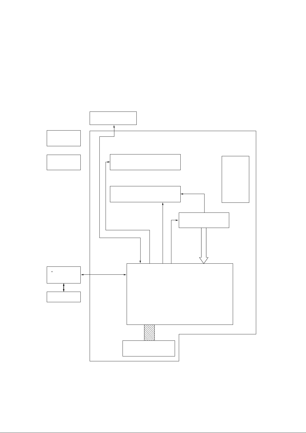
OKIPAGE 6e and OKIPAGE 6ex consist of control and engine blocks in the standard configuration, as shown in Figure 1-1.
In addition, the options marked with asterisk(*) are available.
Operator Panel
(OKIPAGE 6ex Only)
Paper
Cassette
Engine Unit
* Legal/Universal
Paper Tray
* Hight Capacity
Second Paper Feeder
* Multi-Purpose
Feeder
Paper Feed Mechanism
(First Tray Unit)
Electrophotographic
Processing Unit
Main Control PCB
Face
Down
Stacker
Power Supply
and Sensor PCB
*OKIPAGE 6e/6ex : RAM Board
* : Optional
Figure 1-1
Configuration 1 - 1 OKIPAGE 6e/6ex
Service Manual, P/N 59276401
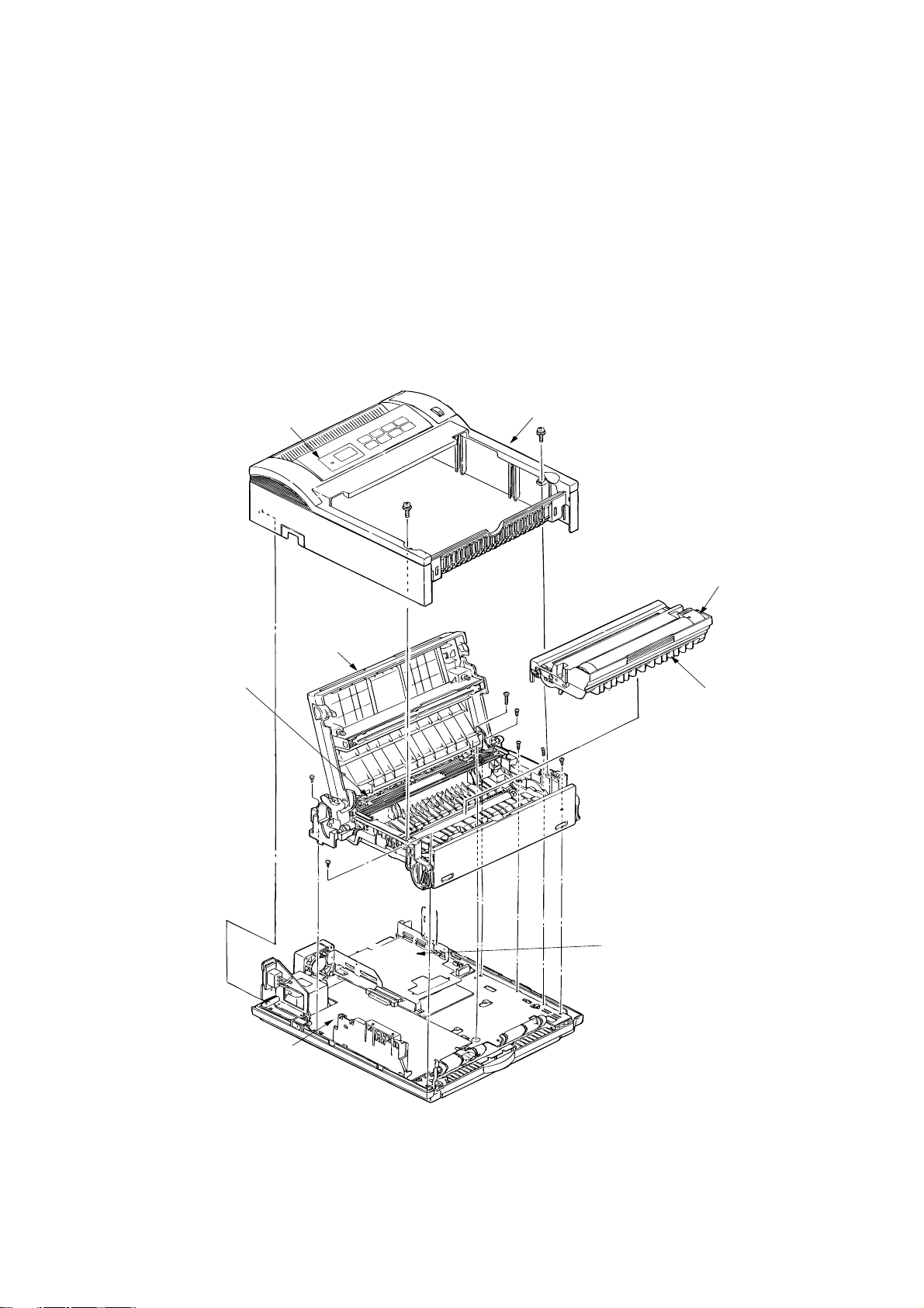
1.2 Printer Configuration
The printer unit consists of the following hardware components:
• Electrophotographic Processor
• Paper Feeder
• Main Control PCB
• Operator Panel (OKIPAGE 6ex Only)
• Power Supply Unit
The printer unit configuration is shown in Figure 1-2.
Operator panel assy
Fusing unit
Upper cover
Toner cartridge
(consumables)
Stacker cover assy
Image drum unit
(consumable)
Main Control PCB
• L5D: OKIPAGE 6e
• L6A: OKIPAGE 6ex
Power supply board
Figure 1-2
Configuration 1 - 2 OKIPAGE 6e/6ex
Service Manual, P/N 59276401
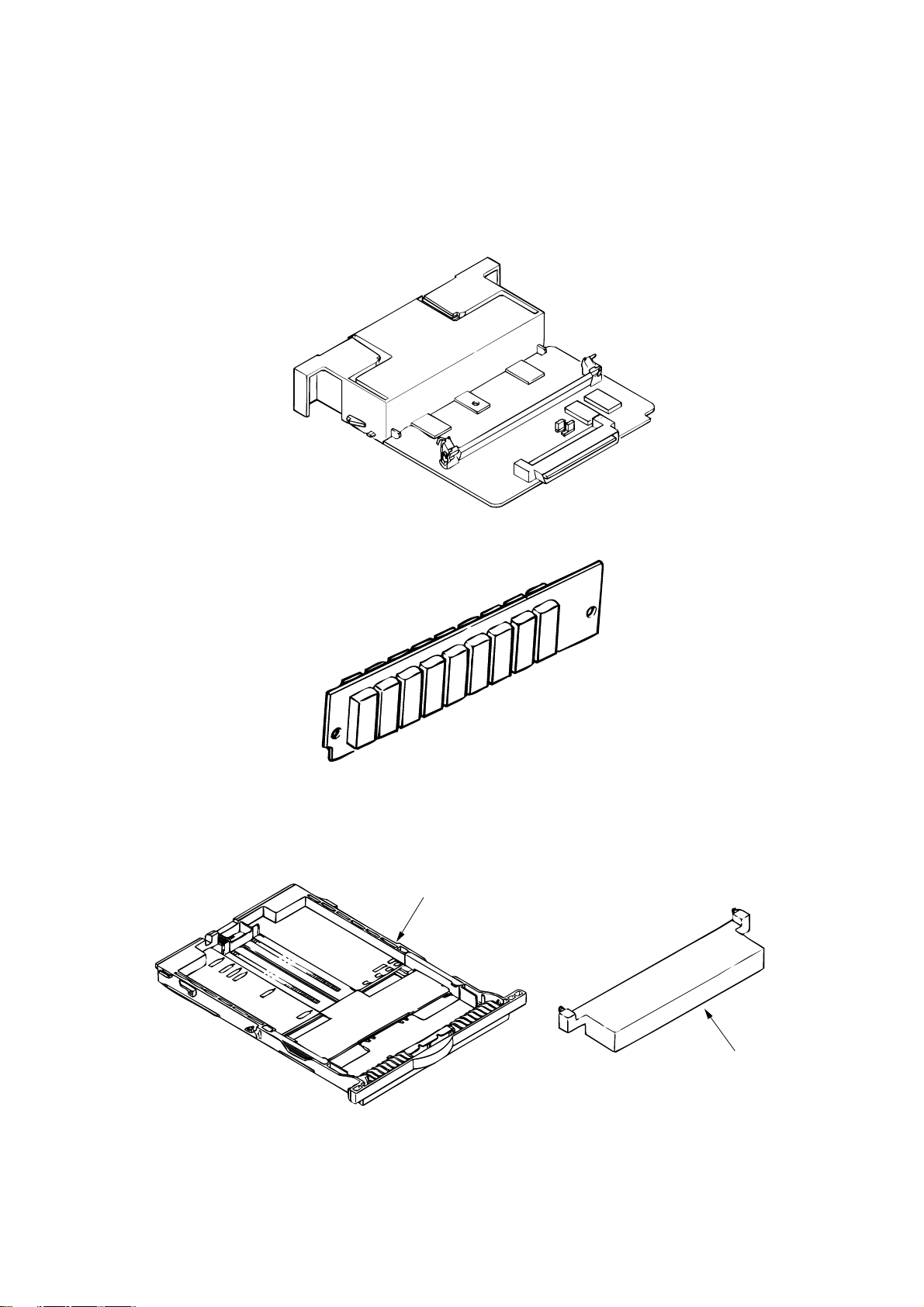
1.3 Optional Configuration
The options shown below are available for use with OKIPAGE 6e and OKIPAGE 6ex. These are
available separately from the printer unit.
(1) 1MB Memory Expansion Board (OKIPAGE 6e/6ex)
(2) SIMM Memory
OKIPAGE 6e :1/2/4/8/16 Mbyte
OKIPAGE 6ex :1/2/4/8/16/32 Mbyte
(3) Legal/Universal Paper Cassette/
Legal/Universal cassette
Cassette cover
Configuration 1 - 3 OKIPAGE 6e/6ex
Service Manual, P/N 59276401
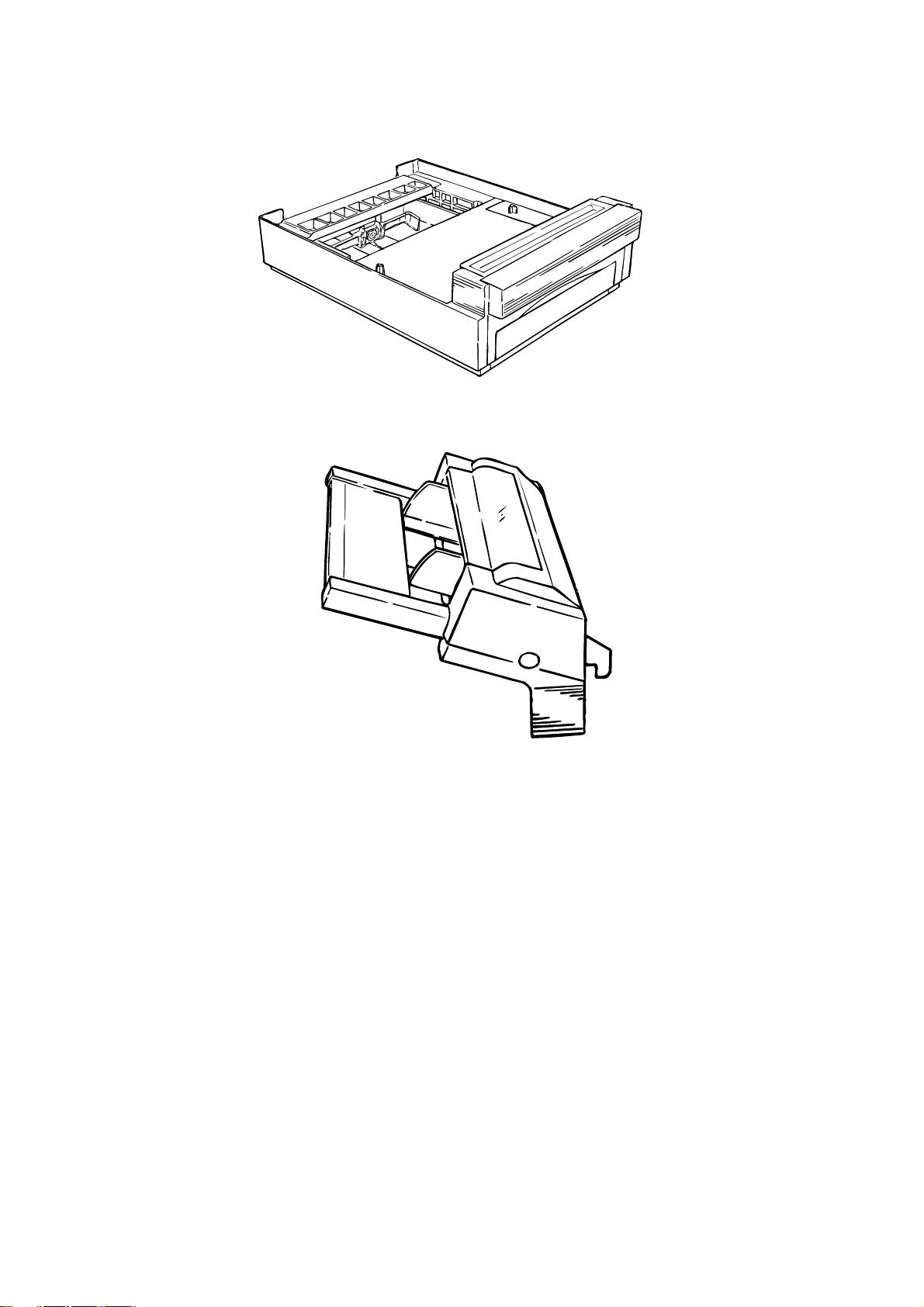
(4) High Capacity Second Paper Feeder
(5) Multi-Purpose Feeder
Configuration 1 - 4 OKIPAGE 6e/6ex
Service Manual, P/N 59276401

1.4 Specification
(1) Type Desktop
(2) External dimensions Height 6.3” (160 mm)
(excludes protruding Width 12.6” (320 mm)
portion) Depth 14.17” (360 mm)
(3) Weight 8 kg
(4) Developing method Dry electrophotography
Exposing method LED stationary head
(5) Paper used <Type>
• Standard paper
– Xerox 4200 (20 lbs)
• Application paper (manual face-up feed)
– Label
– Envelope
– OHP paper (Transparency)
<Size>
• Standard sizes
– Letter (ODA)
– Legal (option)
– Executive
– Envelope
– A4
– A5
– B5
– A6
• Applicable sizes
– Width: 3.94” to 8.5” (100 to 216 mm)
– Length: 5.83” to 14” (148 to 355.6 mm)
<Thickness>
2
– Automatic feed: 16 to 24 lbs (60 to 90 g/m
)
– Manual feed: Label, OHP paper (transparency)
Envelope
(6) Printing speed First print: 17 sec.
Continuous print: 6 sheets/min. for letter size paper
Warm-up time: 60 sec. [at room temperature 77˚F
(25˚C) and rated voltage (120 VAC)]
(7) Paper feeding method Automatic feed or manual feed
(8) Paper delivery method Face down/face up
(9) Resolution 300 x 300 dots/inch (OKIPAGE 6e)
600 x 600 dots/inch (OKIPAGE 6ex)
600 x 1200 dots/inch (OKIPAGE 6ex)
Configuration 1 - 5 OKIPAGE 6e/6ex
Service Manual, P/N 59276401

(10)Power input 120 VAC +5.5%, –15% (ODA)
230 VAC +15%, –15% (ODA)
(11)Power consumption Peak: Approx. 420W
Typical operation: Approx. 160W
Idle: Approx. 55W
Power save mode: Approx. 15W
(12)Temperature and humidity During operation: 50 to 90°F (10 to 32°C)
In storage: 14 to 110°F (–10 to 43°C)
(13) Noise During operation: 48 dB (A) or less
Standby: 38 dB (A) or less
(14)Consumables Toner cartridge kit 2,000 (5% duty)
Image drum cartridge 20,000 (at continuous printing)
15,000 (3 pages/job)
10,000 (1 page/job)
Configuration 1 - 6 OKIPAGE 6e/6ex
Service Manual, P/N 59276401
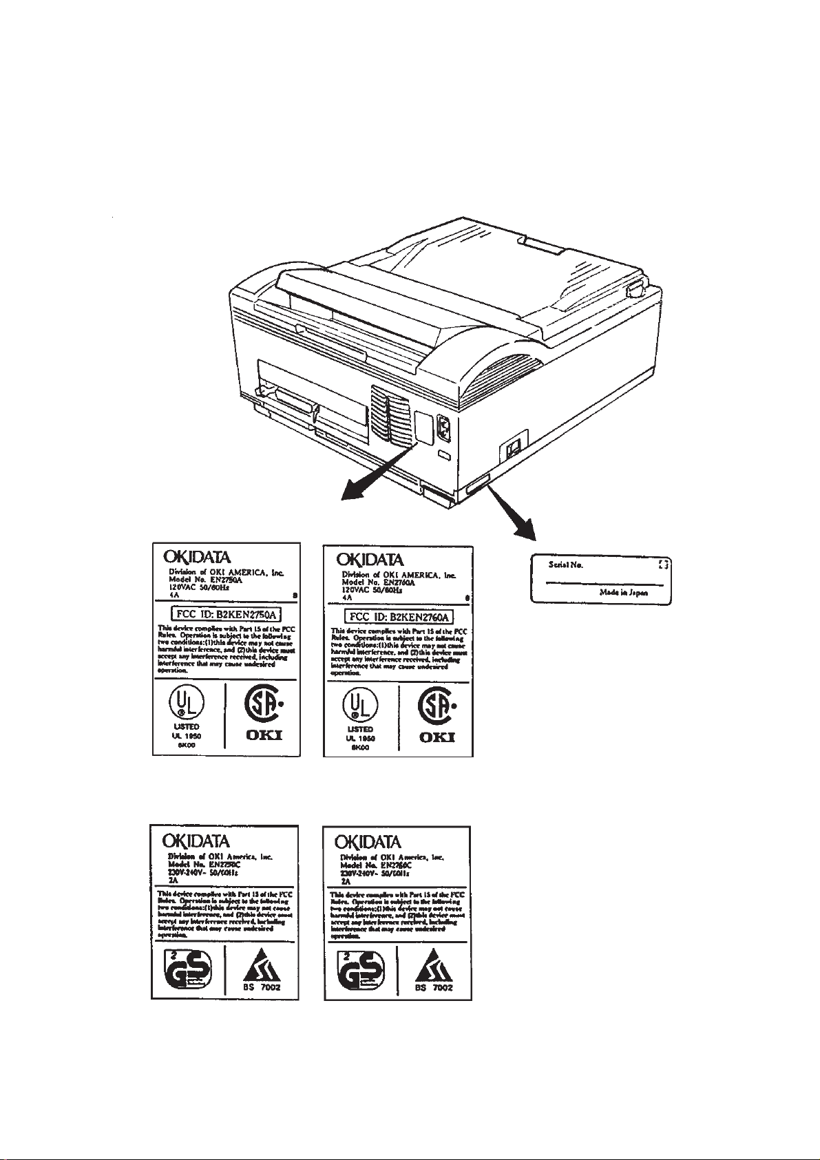
1.5 Safety Standards
1.5.1 Certification Label
The safety certification label is affixed to the printer at the location described below.
OKIPAGE 6e
OKIPAGE 6e
OKIPAGE 6ex
120V
OKIPAGE 6ex
230V
Configuration 1 - 7 OKIPAGE 6e/6ex
Service Manual, P/N 59276401
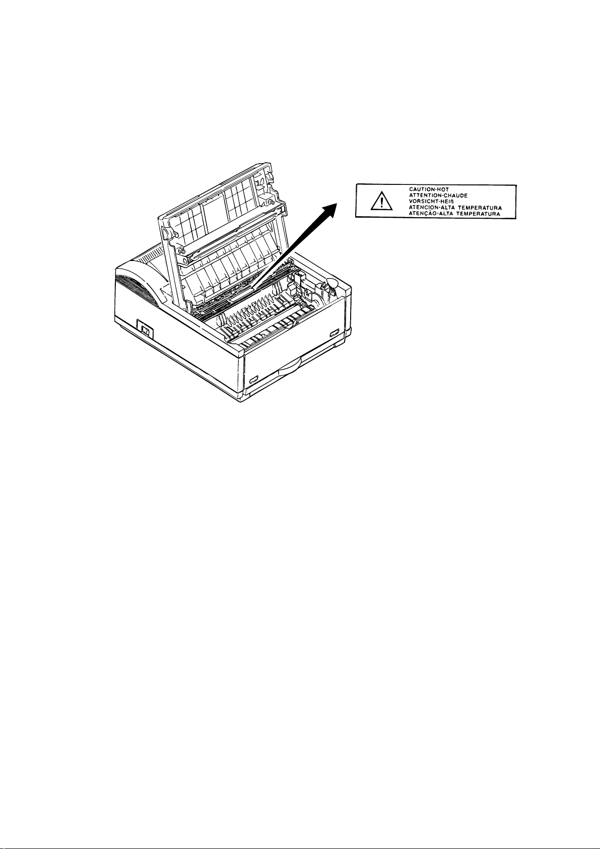
1.5.2 Warning Label
The warning labels are affixed to the sections which may cause bodily injury.
Follow the instructions on warning labels during maintenance.
Configuration 1 - 8 OKIPAGE 6e/6ex
Service Manual, P/N 59276401
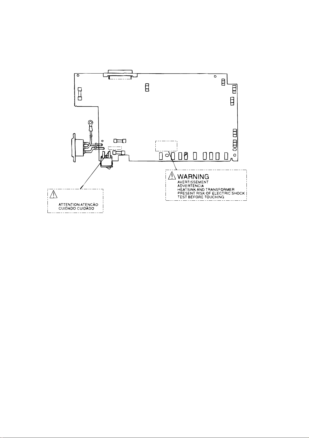
1.5.3 Warning/Caution Marking
The following warning and caution markings are made on the power supply board.
CAUTION
ENGLISH
Heatsink and transformer core present risk of electric shock. Test before touching.
FRENCH
Le dissipateur thermique et le noyau du transformateur présentent des risques de choc
électrique. Testez avant de, manipuler.
SPANISH
Las disipadores de color el núcel del transformador pueden producir un choque eléctrico.
Compruebe antes de tocar.
PORTUGUESE
O dissipador de calor e o núcleo do fransiormador apresentam risco de choque elétrico. Teste
antes de focar.
ENGLISH
Circuits maybe live after fuses open.
FRENCH
Il se peut que les circuits soient sous tension une fois que les fusibles ont éfé rerirés.
SPANISH
Las circuitos pueden estar activos una vez que se hayan abierio los fusibles.
PORTUGUESE
Os circuitos podem estar energizados após os fusiveis se queimarem.
Configuration 1 - 9 OKIPAGE 6e/6ex
Service Manual, P/N 59276401

This page was intentionally left blank.
Configuration 1 - 10 OKIPAGE 6e/6ex
Service Manual, P/N 59276401

2. OPERATION DESCRIPTION
OVERVIEW
OKIPAGE 6e, OKIPAGE 6ex consists of a Main Control PCB, a power supply/sensor board, a
PostScript board (OKIPAGE 6ex), an operator panel and an electrophotographic process mechanism.
The soft operator panel is used for operation and status display of OKIPAGE 6e and OKIPAGE 6ex.
The operator panel is used for operation and status display of OKIPAGE 6ex.
The OKIPAGE 6e and OKIPAGE 6ex receive data via the host I/F, these then decode, edit and store
the data in memory. Bit map image data is successively transferred to the LED head in one dot line
units.
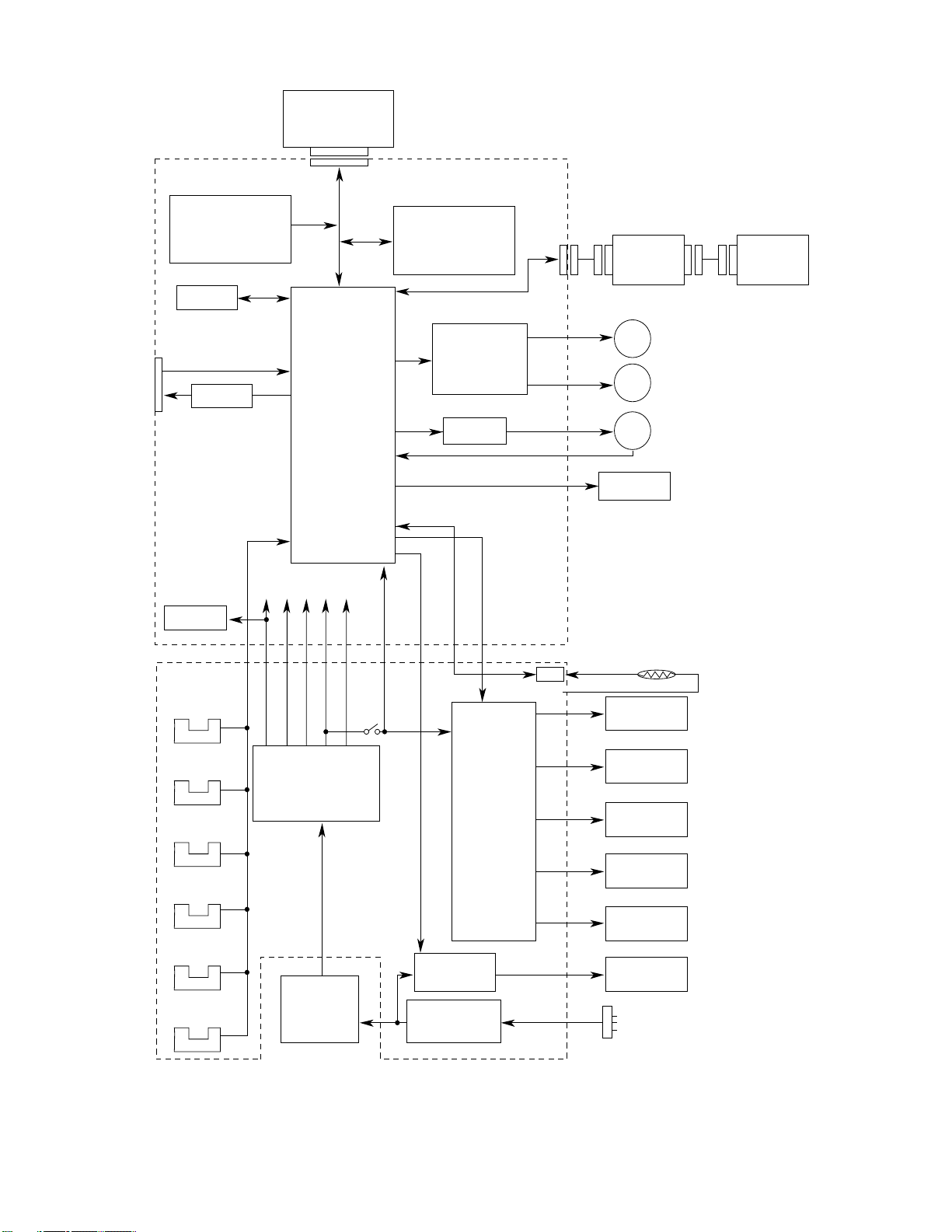
OKIPAGE 6e block diagram is shown in Figure 2-1.
OKIPAGE 6ex block diagram is shown in Figure 2-2.
Operation Description 2 - 1 OKIPAGE 6e/6ex
Service Manual, P/N 59276401
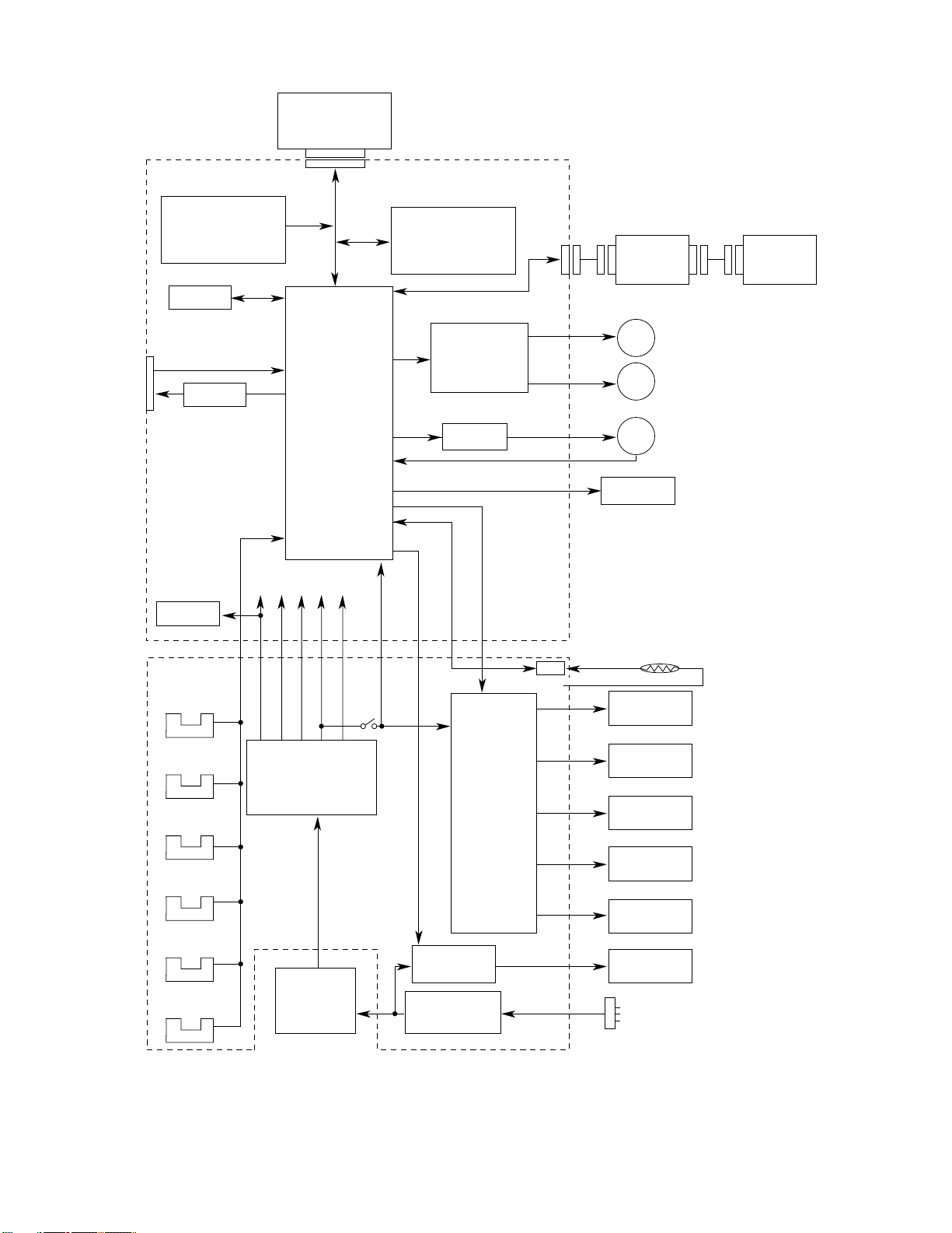
OKIPAGE 6e Block Diagram (Figure 2-1)
1MB Memory Board
(Option)
L5C-
EEPROM
Centronics
parallel I/F
Reset
circuit
Program & Font
ROM
4MB Mask ROM
7407
16 bits
DATA
BUS
1 Chip CPU
+8V -8V 0V +5V
+30V
For optional
RAM board
256k x 16 DRAM x 2
CH TR DB
HEAT ON
Resident RAM
(1M Bytes)
Drum motor &
Registration motor
drive circuit
FAN Driver
FAN ALM
High Capacity
Second Paper
Feeder (Option)
M
M
FAN
LED Head
Drum Motor
Registration Motor
Multi-Purpose
Feeder (Option)
Power Supply
Board
Inlet sensor 1
Inlet sensor 2
Paper sensor
Outlet sensor
Paper out sensor
Toner low sensor
Low voltage
generation circuit
AC
transformer
Cover
open
switch
High voltage
Heater drive
circuit
Filter circuit
generation
circuit
LSI
+5V
Thermistor
Charge roller
Transfer roller
Developing
roller
Toner supply
roller
Cleaning
roller
Heater
AC IN
Operation Description 2 - 2 OKIPAGE 6e/6ex
Service Manual, P/N 59276401
OKIPAGE 6ex Block Diagram (Figure 2-2)
1MB Memory Board
L6A-
Program & Font
4MB Mask ROM
EEPROM
Centronics
parallel I/F
Reset
circuit
ROM
7407
16 bit
32 bit
DATA
BUS
1 Chip CPU
+8V -8V 0V +5V +30V
For optional
RAM board
16 bit
Resident RAM
1M x 16 DRAM
CH TR DB
HEAT ON
(2MB)
Drum motor &
Registration motor
drive circuit
FAN Driver
FAN ALM
High Capacity
Second Paper
Feeder (Option)
Drum Motor
M
Registration Motor
M
FAN
LED Head
Multi-Purpose
Feeder (Option)
Power Supply
Board
Inlet sensor 1
Inlet sensor 2
Paper sensor
Outlet sensor
Paper out sensor
Toner low sensor
Low voltage
generation circuit
AC
transformer
Cover
open
switch
High voltage
Heater drive
circuit
Filter circuit
generation
circuit
LSI
+5V
Thermistor
Charge roller
Transfer roller
Developping
roller
Toner supply
roller
Cleaning
roller
Heater
AC IN
Operation Description 2 - 3 OKIPAGE 6e/6ex
Service Manual, P/N 59276401

2.1 Control Board
The control board consists of a single chip CPU, Program & Font ROM's, one or two DRAMs, an
EEPROM, a host interface circuit, and a mechanism driving circuit.
Single Chip CPU
The single chip CPU is a custom CPU (32-bit internal bus, 16-bit or 32-bit external bus, 25.54 MHz
clock with input frequency from a 12.27 MHz clock) which incorporates the RISC CPU and its
peripheral devices, and has the following functions:
Built-in device Function
Chip select controller Control of ROM, DRAM and I/O device
Bus controller
DRAM controller
DMA controller Transfer of image data from DRAM to video output port
Parallel interface controller Control of Centronics parallel interface
Video output port Control of LED head
LED STB output port
Timer Generation of various control timing
Monitoring of paper running and paper size
Serial I/O port Control of operator panel, EEPROM, and options
I/O port Input and output of sensor and motor signals
Program and Font ROM
The Program & Font ROM store the PCL5e emulation program and various types of fonts.
Mask ROM is used for a Program & Font ROM. The mounting location of this Program & Font ROM
varies depending on the type of ROM (for the mounting location see 7.2).
Operation Description 2 - 4 OKIPAGE 6e/6ex
Service Manual, P/N 59276401

DRAM
The DRAM is a resident memory (OKIPAGE 6e: 1MB/OKIPAGE 6ex: 2MB) used as a buffer, and
it stores edited data, image data, DLL data and macro data.
EEPROM
1,024 bit-Electrically Erasable PROM (EEPROM), is loaded with the following kinds of data:
Parallel Interface
Parallel data is received from the host system via parallel interface which conforms to the
Centronics specification. IEEE 1284 Bi-directional parallel is supported.
• Menu data
• Various counter data (Page counter, Drum counter)
• Adjusting parameters (LED head drive time, print start position, paper feed length)
Operation Description 2 - 5 OKIPAGE 6e/6ex
Service Manual, P/N 59276401

2.2 PS Board (Option)
This board is not included in the current configuration of the product.
Operation Description 2 - 6 OKIPAGE 6e/6ex
Service Manual, P/N 59276401
2.3 RAM Board (OKIPAGE 6e/6ex option)
The RAM board consists of DRAM's and a SIMM socket.
DRAM
1MB of DRAM's reside on the RAM board.
SIMM Socket
One SIMM socket is mounted on the RAM board.
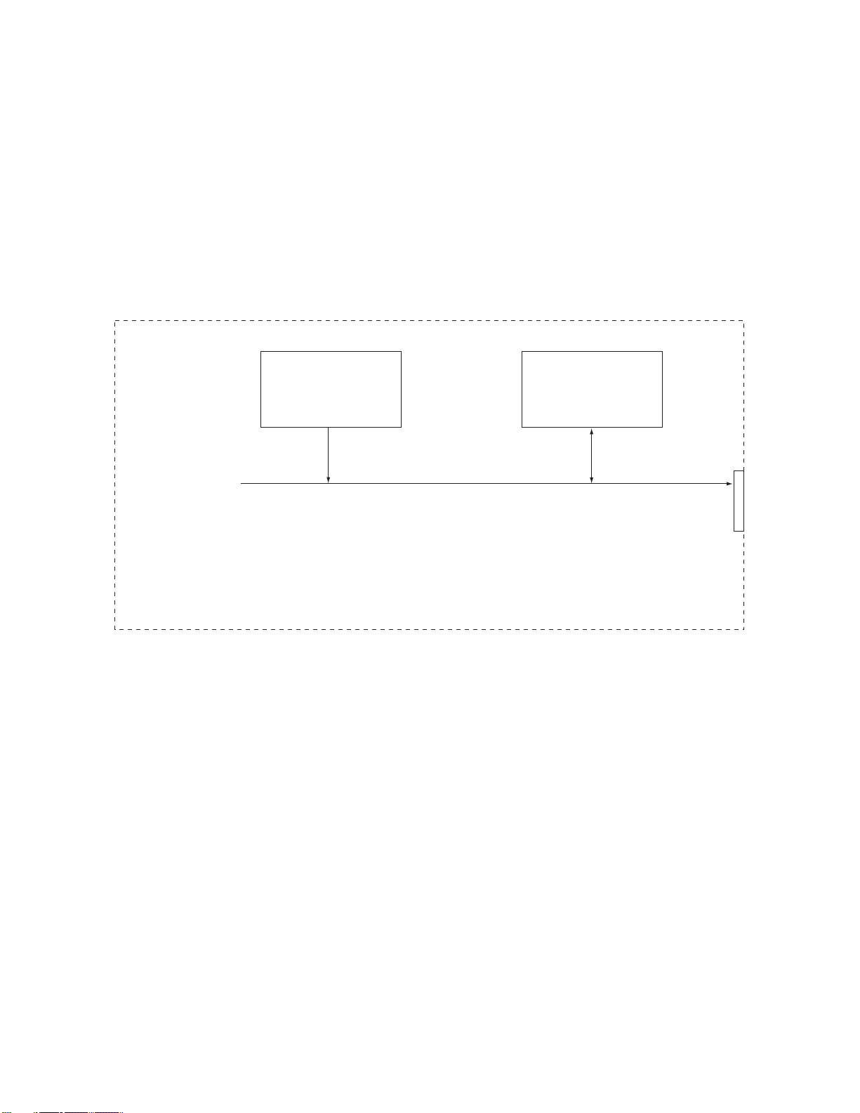
RAM Board Block Diagram (Figure 2-4)
SIMM Socket
Resident RAM
(1MB)
Operation Description 2 - 7 OKIPAGE 6e/6ex
Service Manual, P/N 59276401
 Loading...