

Okidata OKIPAGE 14ex Service Manual

Thank You for purchasing this
Click Here for more Factory Service
Manuals for other Computer and
Printer / Copier Manufacturers
from PCTECHINFO!
OKIPAGE 14ex
LED Page Printer
SERVICE
MANUAL

Table of Contents Page
Service Manual for OKIPAGE 14ex
0 Introduction
Introduction 1
1 Specifications
1.1 System Configuration 2
1.2 Printer Configuration 3
1.3 Optional Configuration 4
1.4 Specification 5
1.5 Safety Standards 6
....1.5.1 Certification Label 7
....1.5.2 Warning Label 8
....1.5.3 Warning/Caution Marking 9
2 Operation
Operation Description 10
2.1 Main Control Board 11
2.2 Power Supply/Sensor Board 12
2.3 Electrophotographic Process 13
....2.3.1 Electrophotographic Process Mechanism 14
....2.3.2 Electrophotographic Process 15
....2.3.3 Process Operation Descriptions 16
....2.3.4 Revision of LED Head Illumination 17
2.4 Paper Jam Detection 18
2.5 Cover Open 19
2.6 Toner Low Detection 20
3 Disassembly
3.1 Precautions for Parts Replacement 21
3.2 Parts Layout - [Lower base unit] 22
........[Upper cover unit] 23
........[Base unit] 24
3.3 How to Change Parts 25
....3.3.1 Upper Cover Assy 26
....3.3.2 LED Head 28
....3.3.3 Operator Panel Assy 29
....3.3.4 Lower Base Unit 30
....3.3.5 Pulse Motor Main/Drum 31
....3.3.6 Pulse Motor (Registration) 32

Table of Contents Page
....3.3.7 Face Up Stacker Assy 33
....3.3.8 Eject Roller Assy 34
....3.3.9 Motor Assy 35
....3.3.10 Hopping Roller Shaft Assy 36
....3.3.11 Stacker Cover Assy 37
....3.3.12 Registration Roller 38
....3.3.13 Roller Transfer Assy 39
....3.3.14 Fusing Unit 40
....3.3.15 Back-up Roller 41
....3.3.16 Sensor Plate (Inlet) 42
....3.3.17 Sensor Plate (Outlet), Sensor Wire Assy 43
....3.3.18 Manual Feed Guide Assy 44
....3.3.19 Sensor Plate (Paper Supply) 45
....3.3.20 Main Control M7E-PCB 46
....3.3.21 Power Supply/Sensor Board, High Voltage Unit and
Contact Assy
....3.3.22 Cassette Guide L Assy 49
....3.3.23 Cassette Guide R Assy 50
....3.3.24 Spacer Bearing (L/R) 51
4 Adjustments
4. Adjustment 52
....4.1 Maintenance Modes and Functions 53
........4.1.1 User Maintenance Mode 54
........4.1.2 System Maintenance Mode 55
........4.1.3 Engine Maintenance Mode 56
........4.1.4 EEPROM Initialization 57
....4.2 Adjustment When Replacing a Part 58
........4.2.1 Uploading/Downloading EEPROM data 60
5 Maintenance
5.1 Periodical Replacement Parts 61
5.2 Cleaning 62
....5.2.1 Cleaning of LED Lens Array 63
....5.2.2 Cleaning Page Function 64
6 Troubleshooting
6.1 Troubleshooting Tips 65
6.2 Points to Check before Correcting Image Problems 66
47

Table of Contents Page
6.3 Tips for Correcting Image Problems 67
6.4 Preparation for Troubleshooting 68
6.5 Troubleshooting Flow 69
....6.5.1 LCD Status Message/Problem List 70
....6.5.2 LCD Message Troubleshooting 71
........(1) The printer does not work normally after the power is
turned on.
........(2) [JAM error] 73
............Paper input jam 74
............Paper feed jam 75
............Paper exit jam 76
........(3) Paper size error 77
........(4) Fusing unit error (ERROR 71) (ERROR 72) (ERROR
73)
........(5) SSIO error (ERROR 74) 79
........(6) Fan error (ERROR 70) 80
....6.5.3 Image Troubleshooting 81
........(1) Images are light or blurred entirely 82
........(2) Dark background density 83
........(3) Blank paper is output 84
........(4) Black vertical belts or stripes 85
........(5) Cyclical defect 86
........(6) Prints voids 87
........(7) Poor fusing 88
........(8) Vertical belts or streaks 89
........Figure 6-4 90
........Figure 6-5 91
7 Wiring Diagram
7.1 Interconnect Signal Diagram 92
7.2 PCB Layout and Connector Signal List 93
7.3 Resistance Check 94
8 Parts List
Lower Base Unit 96
Upper Cover Unit 97
Base Unit 98
A Centronics Parallel Interface
72
78

Table of Contents Page
Centronics Parallel Interface 99
B Universal Serial Bus (USB)
Universal Serial Bus (USB)
C Loop Test (RS-232C Interface)
Loop Test (RS-232C Interface) 100
D Diagnostics Test
1. Maintenance Modes 101
....1.1 User Maintenance Mode 102
....1.2 System Maintenance Mode 103
....1.3 Engine Maintenance Mode 104
....1.4 User Factory Set Operation 105
Product Accessory 1: RS-232C Serial Interface (Option)
RS-232C Serial Interface (Option) 106
Product Accessory 2: Multi-Purpose Feeder Maintenance
1. PREFACE 107
....1.1 Functions 108
....1.2 External View and Component Names 109
2. MECHANISM DESCRIPTION - General Mechanism 110
....2.2 Hopper Mechanism 111
3. PARTS REPLACEMENT 112
....3.1 Precautions Concerning Parts Replacement 113
....3.2 Parts Layout 114
....3.3 Parts Replacement Methods 115
........3.3.1 Link 116
........3.3.2 Separator 117
........3.3.3 OLEV-11 PCB 118
........3.3.4 Pulse Motor 119
........3.3.5 Planet Gear 120
........3.3.6 Roller-A and B 121
4. TROUBLESHOOTING - Precautions Prior to the
Troubleshooting
....4.1 Precautions Prior to the Troubleshooting 122
....4.2 Preparations for the Troubleshooting 123
....4.3 Troubleshooting Method 124
........4.3.1 LCD Status Message List 125
5. CONNECTION DIAGRAM 126
122

Table of Contents Page
....5.1 Interconnection Diagram 126
....5.2 PCB Layout 127
6. PARTS LIST 128
Product Accessory 3: High Capacity 2nd Paper Feeder
High Capacity Second Paper Feeder Maintenance 129
1. OUTLINE 130
....1.1 Functions 130
....1.2 External View and Component Names 131
2. MECHANISM DESCRIPTION - General Mechanism 132
....2.1 General Mechanism 132
....2.2 Hopper Mechanism 133
3. PARTS REPLACEMENT 134
....3.1 Precautions Concerning Parts Replacement 135
....3.2 Parts Layout 136
....3.3 Parts Replacement Methods 137
........3.3.1 Stepping Motor (Hopping) 138
........3.3.2 TQSB-2 PCB 139
........3.3.3 Hopping Roller Shaft Assembly and One-way Clutch
Gear
4. TROUBLESHOOTING - Precautions Prior to the
Troubleshooting
....4.1 Precautions Prior to the Troubleshooting 141
....4.2 Preparations for the Troubleshooting 142
....4.3 Troubleshooting Method 143
........4.3.1 LCD Status Message List 144
5. CONNECTION DIAGRAM 145
....5.1 Interconnection Diagram 146
....5.2 PCB Layout 147
6. PARTS LIST 148
....High Capacity Second Paper Feeder 148
....SECTION 1 CABINET & CASSETTE ASSEMBLY 150
....SECTION 2 MECHANICAL ASSEMBLY 151
....2nd Tray Parts List 152
140
141

Page: 2
Service Manual for OKIPAGE 14ex
Chapter 0 Introduction
Introduction
This Service Handbook describes the field maintenance methods for OKIPAGE 14ex Digital LED Printer. This manual is written for use by the maintenance
personnel. Please note that you should refer to the Printer Handbook and Printer Setup for the handling and operating methods of the equipment.
Copyright 2000, Oki Data, Division of OKI America, Inc. All rights reserved. See the Oki Data Business Partner Exchange
(BPX) for any updates to this material. (http://bpx.okidata.com)

Service Manual for OKIPAGE 14ex
1.1 System Configuration
OKIPAGE 14ex consists of control and engine blocks in the standard configuration, as shown in Figure 1-1.
In addition, the options marked with asterisk (*) are available.
Chapter 1 Specifications
Page: 3
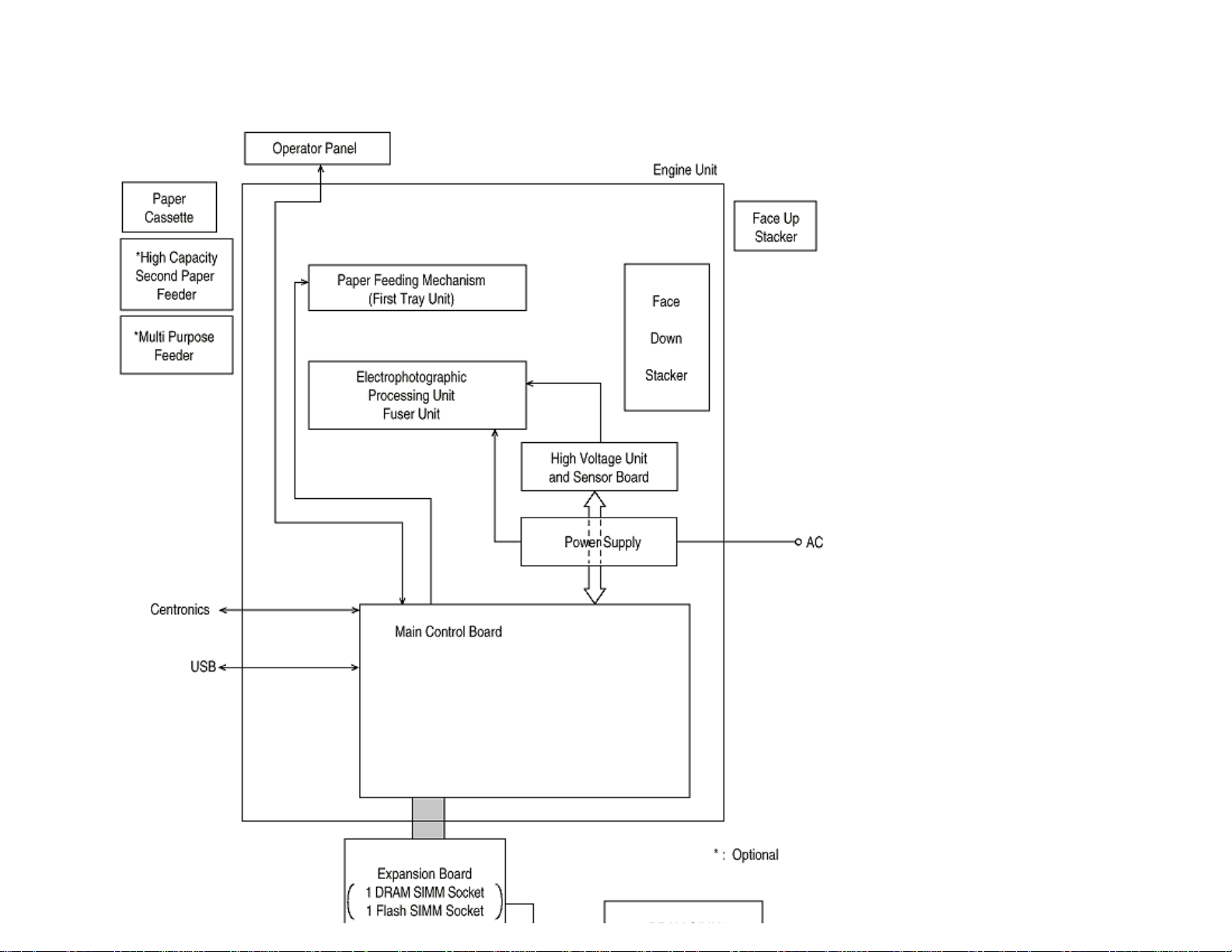

Figure 1-1
Copyright 2000, Oki Data, Division of OKI America, Inc. All rights reserved. See the Oki Data Business Partner Exchange
(BPX) for any updates to this material. (http://bpx.okidata.com)

Service Manual for OKIPAGE 14ex
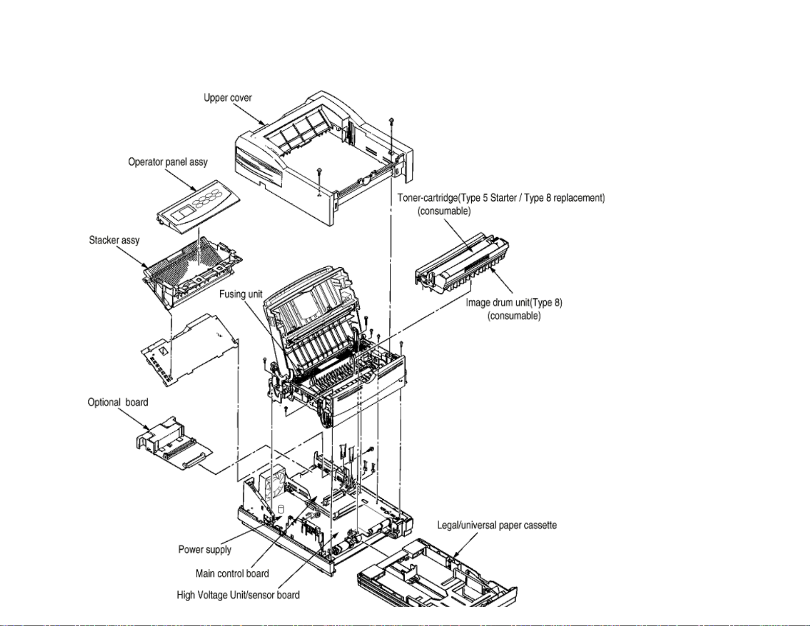
1.2 Printer Configuration
The printer unit consists of the following hardware components:
Electrophotographic Processorl
Paper Feederl
Controllerl
Operator Panell
Power Supply Unitl
The printer unit configuration is shown in Figure 1-2.
Chapter 1 Specifications
Page: 4

Copyright 2000, Oki Data, Division of OKI America, Inc. All rights reserved. See the Oki Data Business Partner Exchange
(BPX) for any updates to this material. (http://bpx.okidata.com)
Page: 5
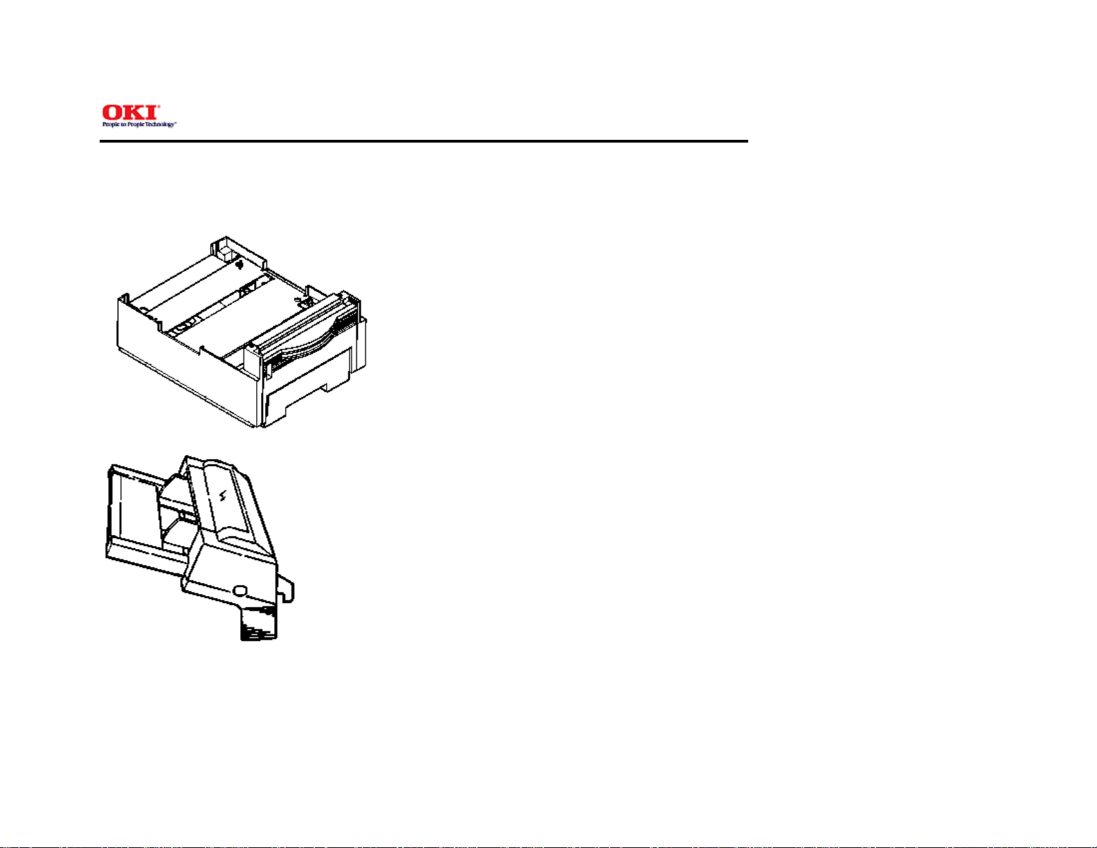
1.3 Optional Configuration
Service Manual for OKIPAGE 14ex
Chapter 1 Specifications
The options shown below are available for use with OKIPAGE 14ex. These are available separately from the printer unit.
(1) High Capacity Second Paper Feeder
(2) Multi-Purpose Feeder
(3) 1 MB Memory Expansion Board
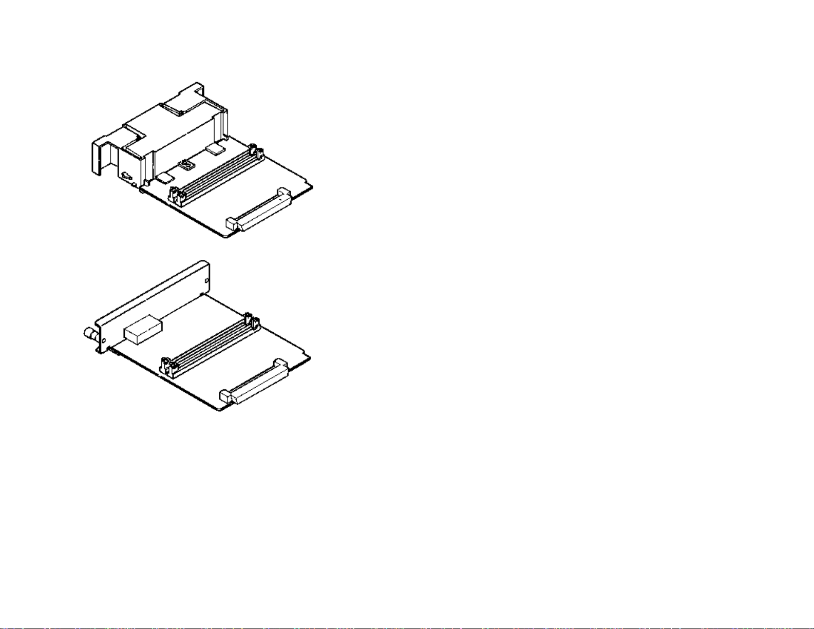
(4) RS-232C Serial Interface Board
(5) DRAM SIMM Memory
DRAM SIMM memory is available with memory of 1 MB (min.) to 32 MB (max.). The access time of SIMM memories are 60ns, 70ns, 80ns, and 100ns.
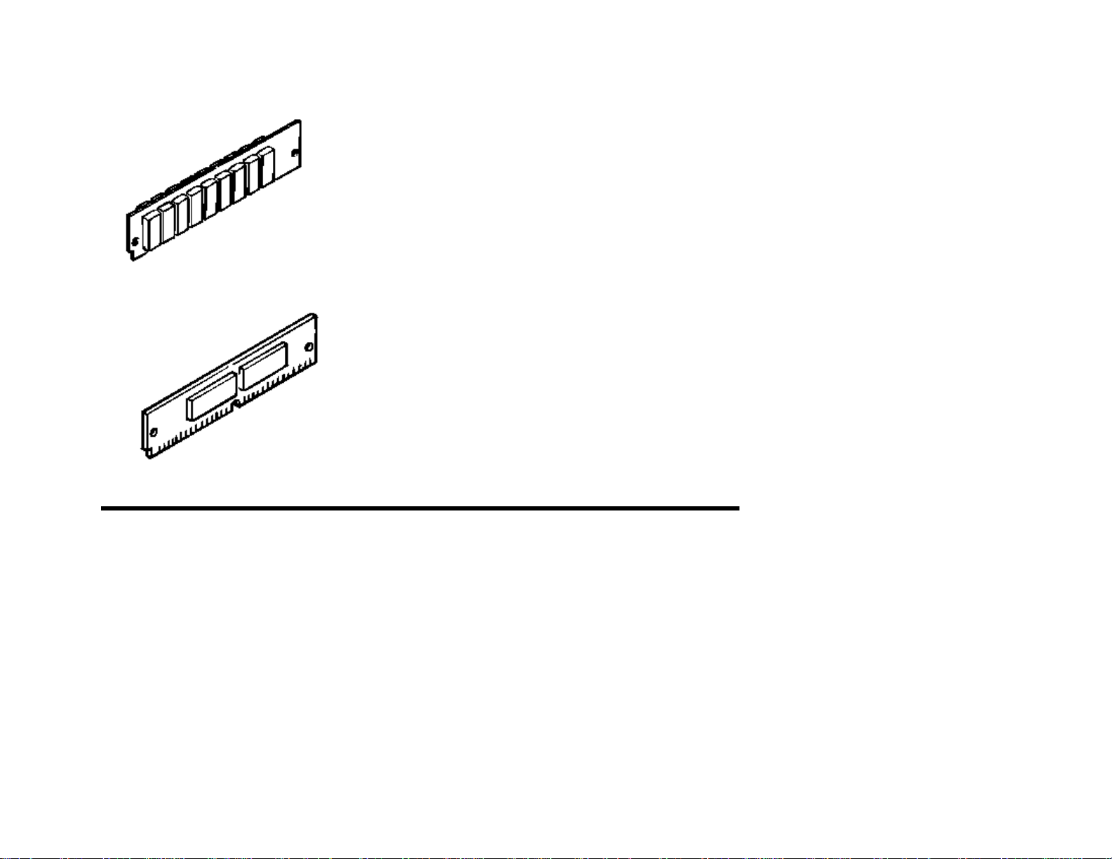
(6) Flash SIMM
Flash SIMM is available with memory of 4 MB and 8 MB.
Copyright 2000, Oki Data, Division of OKI America, Inc. All rights reserved. See the Oki Data Business Partner Exchange
(BPX) for any updates to this material. (http://bpx.okidata.com)

Service Manual for OKIPAGE 14ex
1.4 Specification
(1) Type: Desktop
(2) Outside dimensions Height: 8.5" (215 mm)
(3) Weight 19.8 lbs.
Chapter 1 Specifications
Width 13.6" (345 mm)
Depth 15.6" (395mm)
Page: 6
(4) Development
Dry electrophotography LED stationary head
method
Exposure method
(5) Paper used <Type>
Standard paperl
- Xerox 4200 (20 lbs)
Application paper (manual face-up feed)l
- Label
- Envelope
- OHP paper (Transparency)
<Size>
Standardl
Letter
Legal * [*Without Mutli-Purpose Feeder (Option)]
Legal-13*
Executive
-COM-10** [**manual feed and Multi-Purpose Feeder
(Option) only]
Monarch**
DL**
C5**
B5 (JIS)
A6
Applicable sizesl

- Width: 3.4" x 8.5" (86 to 216 mm)
- Length: 5.5" to 14" (140 to 355.6 mm)
<Thickness>
- Automatic feed: 16 to 28 lbs (60 to 135 g/m2)
- Manual feed: Label, OHP paper (transparency), Envelope
(24 to 28 lbs.)
(6) Printing speed: First print: 14 seconds typical for the Letter size paper.
[Except Multi-Purpose Feeder (11ppm)]
Warm-up time: 45 seconds typical at room temperature [68o
F (20o C), AC 120/230 V].(120 VAC for ODA, 230 VAC for
OEL/INT)
First page print time: 7.5 seconds typical for the Letter size
paper after warm-up.
(7) Paper feeding
Automatic paper feed or manual paper feed
method
(8) Paper delivery
Face down/face up
method
(9) Resolution 600 dpi x 600 dpi (true)
600 x 1200 dots/inch graphics
(10) Power input 120 VAC + 5.5%, -15%
230 VAC +/- 10%
(11) Power consumption Peak: Approx. 600W
Typical operation: Approx. 340W
Idle: Approx. 75W
Power save mode: Approx. 10W
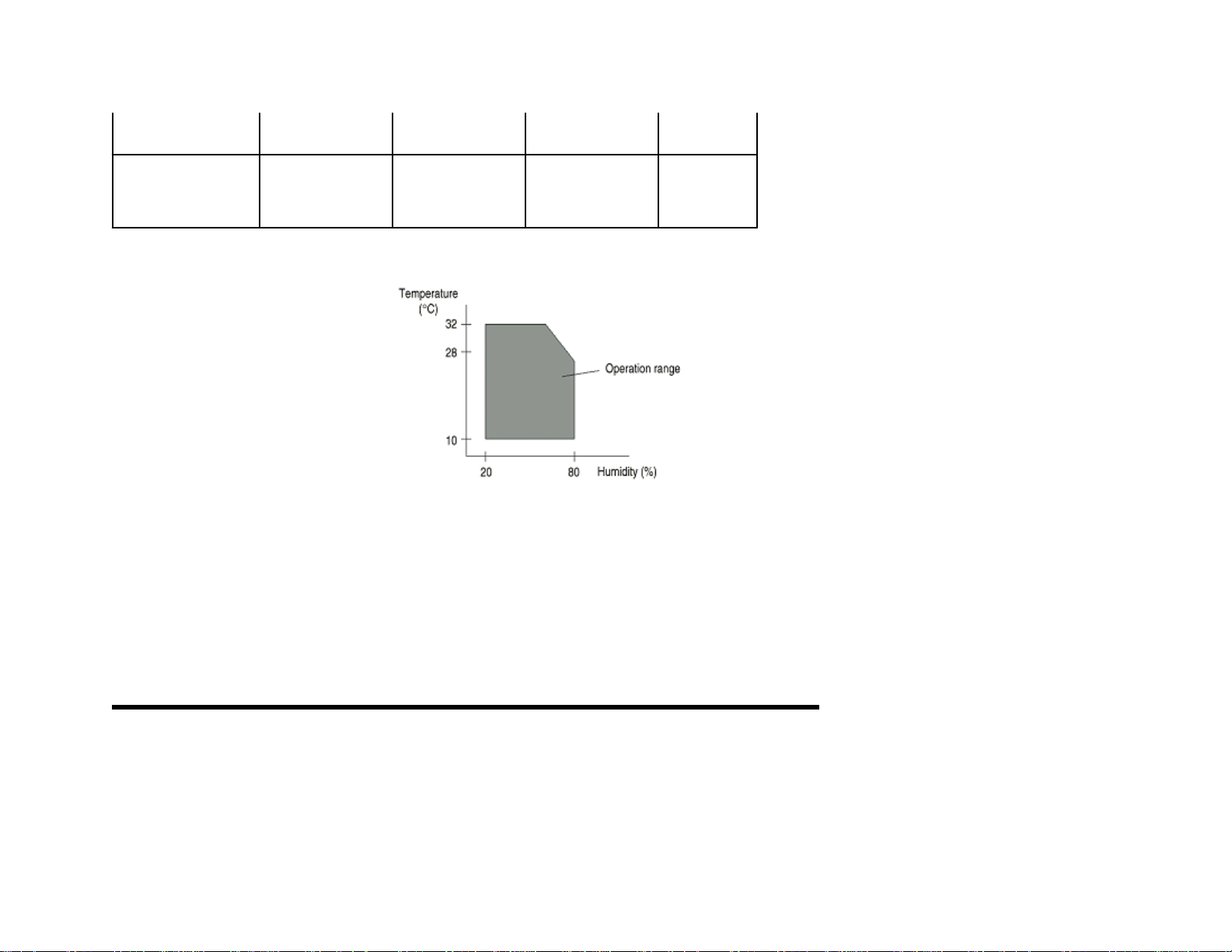
(12) Temperature and
humidity
In operation Power off mode During Storage Unit
Temperature 50-90
(10-32)
32-110
(0-43)
14-110
(-10-43)
Humidity 20-80 10-90 10-90 %RH
Maximum wet bulb 77 80.4 -----
o
F
o
C
temperature (25) (26.8)
Minimum
difference between
35.6
(2)
35.6
(2)
-----
wet and dry bulb
temperatures
1. Storage conditions specified above apply to printers in packed condition.
2. Temperature and humidity must be in the range where no condensation occurs.
(13) Noise During operation: 53 dB (A) or less
Standby: 38 dB (A) or less
Quite mode: Back ground level
o
F
o
C
o
F
o
C
(14) Consumables Toner cartridge kit - 2,000 (Type 5) (5% duty)
Toner cartridge option - 4,000 (Type 8) (5% duty)
Image drum cartridge - 20,000 (at continuous printing);
14,000
(3 page/job) without Power Save
Copyright 2000, Oki Data, Division of OKI America, Inc. All rights reserved. See the Oki Data Business Partner Exchange
(BPX) for any updates to this material. (http://bpx.okidata.com)

Page: 7
Service Manual for OKIPAGE 14ex
Chapter 1 Specifications
1.5 Safety Standards
1.5.1 Certification Label
1.5.2 Warning Label
1.5.3 Warning/Caution Marking
Copyright 2000, Oki Data, Division of OKI America, Inc. All rights reserved. See the Oki Data Business Partner Exchange
(BPX) for any updates to this material. (http://bpx.okidata.com)
Service Manual for OKIPAGE 14ex
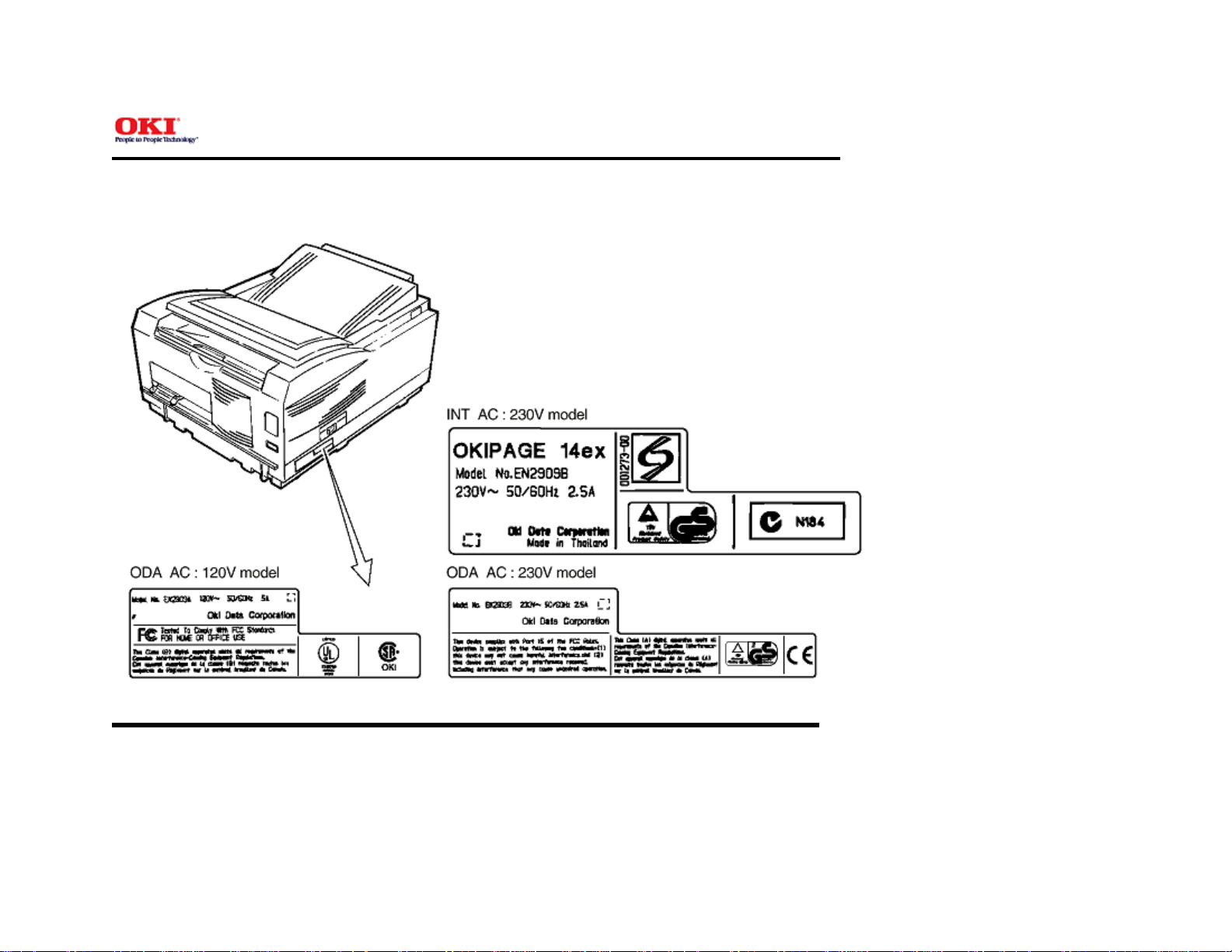
1.5.1 Certification Label
The safety certification label is affixed to the printer in the position described below.
Chapter 1 Specifications
Page: 8
Copyright 2000, Oki Data, Division of OKI America, Inc. All rights reserved. See the Oki Data Business Partner Exchange
(BPX) for any updates to this material. (http://bpx.okidata.com)
Service Manual for OKIPAGE 14ex
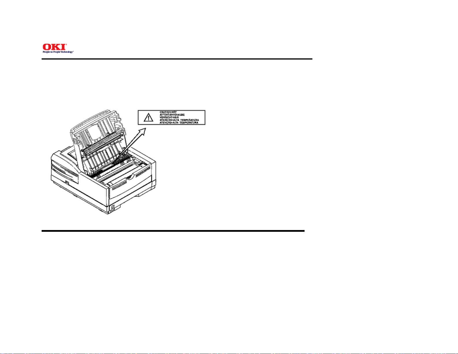
1.5.2 Warning Label
The warning labels are affixed to the sections which may cause bodily injury.
Follow the instructions on warning labels during maintenance.
Chapter 1 Specifications
Page: 9
Copyright 2000, Oki Data, Division of OKI America, Inc. All rights reserved. See the Oki Data Business Partner Exchange
(BPX) for any updates to this material. (http://bpx.okidata.com)

Service Manual for OKIPAGE 14ex
1.5.3 Warning/Caution Marking
The following warning and caution markings are made on the power supply/sensor board.
Chapter 1 Specifications
Page: 10
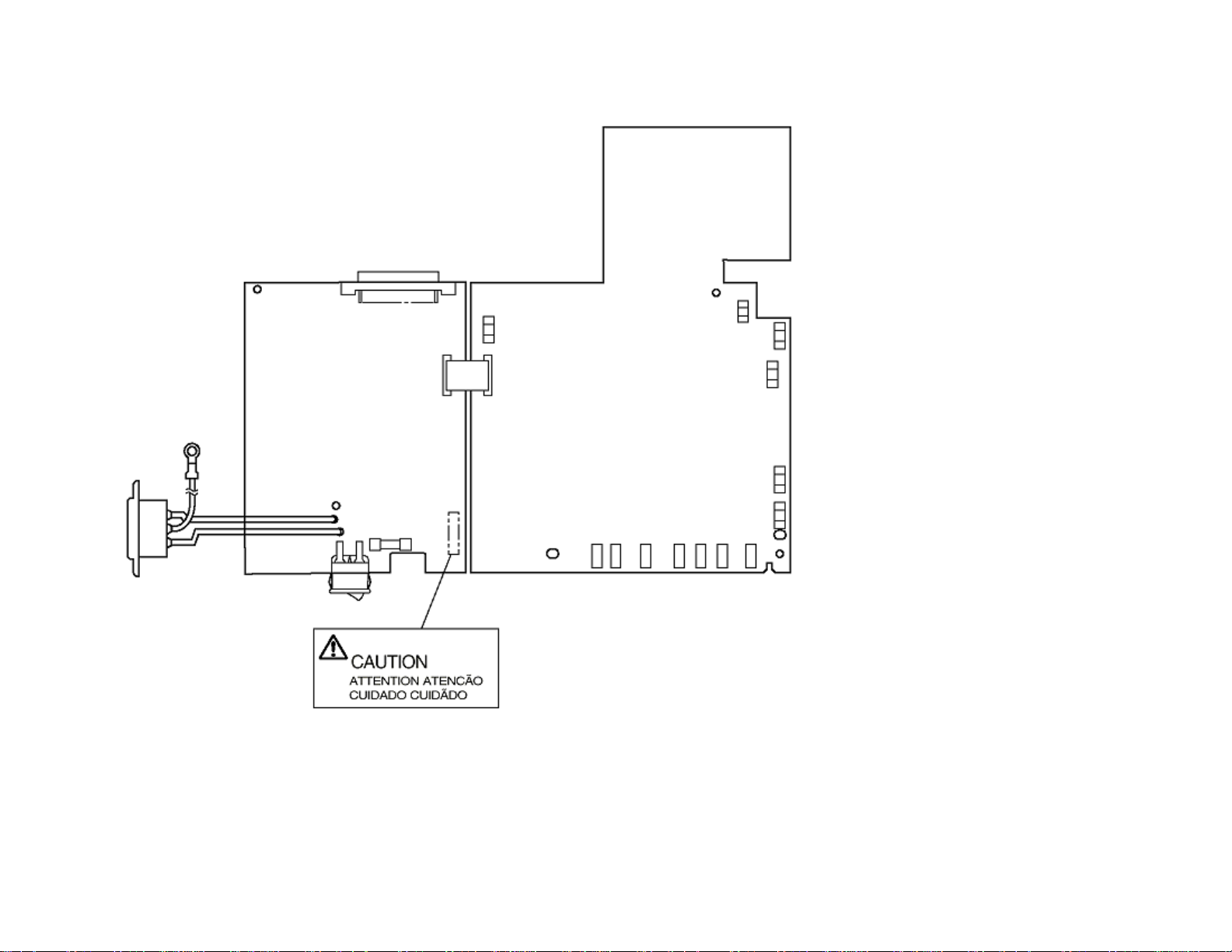
* No fuse is mounted here for 200V series.
ENGLISH - Heatsink and transformer core present risk of electric shock. Test before touching.
FRENCH - Le dissipateur thermique et le noyau du transformateur présentent des risques de choc électrique. Testez avant de manipuler.
SPANISH - Las disipadores de color el núcel del transformador pueden producir un choque eléctrico. Compruebe antes de tocar.

PORTUGUESE - O dissipador de calor e o núcleo do fransiormador apresentam risco de choque elétrico. Teste antes de focar.
ENGLISH - Circuits maybe live after fuses open.
FRENCH - Il se peut que les circuits soient sous tension une fois que les fusibles ont éfé rerirés.
SPANISH - Las circuitos pueden estar activos una vez que se hayan abierio los fusibles.
PORTUGUESE - Os circuitos podem estar energizados após os fusiveis se queimarem.
Copyright 2000, Oki Data, Division of OKI America, Inc. All rights reserved. See the Oki Data Business Partner Exchange
(BPX) for any updates to this material. (http://bpx.okidata.com)

Page: 11
Operation Description
Service Manual for OKIPAGE 14ex
Chapter 2 Operation
OKIPAGE 14ex consists of a main control board, a power supply/sensor board, an operator panel, an electrophotographic process mechanism, and revision for
illumination of LED head.
The main control board receives data via the host I/F, it then decodes, edits and stores the data in memory. After completing the editing of a single page of data,
it references the font memory and generates bit image data, which is transferred to the LED head in one dot line units.
Through the electrophotographic process mechanism, the data is printed on the paper.
The operator panel is used for operations and status display.
OKIPAGE 14ex block diagram is shown in Figure 2-1.


Copyright 2000, Oki Data, Division of OKI America, Inc. All rights reserved. See the Oki Data Business Partner Exchange
(BPX) for any updates to this material. (http://bpx.okidata.com)
Service Manual for OKIPAGE 14ex
2.1 Main Control Board
The main control board consists of a single chip CPU, two program/font ROMs, four DRAMs, an EEPROM, a host interface circuit, and a mechanism driving
circuit.
(1) Single chip CPU
The single chip CPU is a custom CPU (32-bit internal bus, 32-bit external bus, 32-bit external bus, 49.766-MHz clock, which incorporates the RISC CPU and its
peripheral devices, and has the following functions:
Chapter 2 Operation
Page: 12
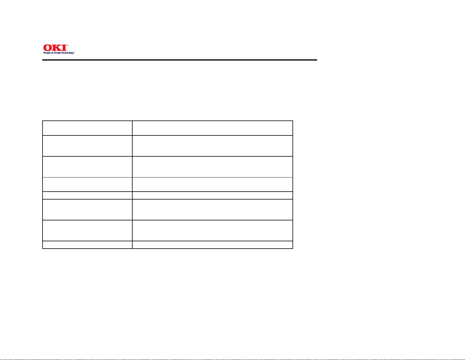
Built-in Device Function
Chip select controller
Control of ROM, DRAM and I/O device.
Bus controller
DRAM controller
DMA controller Transfer of image data from DRAM to video output
port.
Parallel interface controller Control of Centronics parallel interface.
Serial interface controller Control of RS-232C serial interface.
Video output port
Controls LED head.
LED STB output port
Timer Generation of various control timing
Monitoring of paper running and paper size.
I/O Port Input and output of sensor and motor signals.
(2) Program and Font ROMs
The Program and Font ROMs store the equipment program and various types of fonts. Mask ROM is used as Program and Font ROMs. The mounting locations
of these Program and Font ROMs vary depending on the type of the ROMs.
(3) DRAM
The DRAM is a 2MB resident memory on the main control board that stores edited data, image data, DLL data and macro data.
(4) EEPROM
4,096-bit Electrically Erasable PROM (EEPROM), is loaded with the following kinds of data:
 Loading...