


Thank You for purchasing this
Click Here for more Factory Service
Manuals for other Computer and
Printer / Copier Manufacturers
from PCTECHINFO!

OKIOFFICE 44
Service Manual
All specifications are subject to change without notice.
59276801

Disclaimer
This document may not be reproduced without the written permission of OKIDATA Training and
Publications. Evert effort has been made to ensure the accuracy of the information contained in this
training course. OKIDATA is not responsible for errors beyond its control.
Copyright / About Information
Copyright 1997 by OKIDATA. All rights reserved.
First Release P/N 59276801 September, 1997
Written by OKIDATA Training and Publications
Contact Information
Please address any comments on this publication to:
Mailing Address OKIDATA
532 Fellowship Road
Mount Laurel, NJ 08054-3499
Web Site www.OKIDATA.com
Telephone (609) 235-2600
Facsimile (609) 222-5320
OKILINK Login Name Technical Training
Copyright Listing
OKIDATA is a registered trademark of Oki Electric Industry Company, Ltd.; marques deposee de Oki
Electric Industry Company, Ltd.; marca registrada, Oki Electric Industry Company, Ltd.
Faxable Facts is a trademark, All Rights Reserved, 1993
IBM, PC, PC-DOS, and Proprinter XL are registered trademarks of International Business Machines
Corporation.
Microsoft and MS-DOS are registered trademarks and Microsoft Basic, Windows, TrueImage, and
TrueType are trademarks of Microsoft Corporation.
OKILINK II is a trademark of Oki Electric Industry Company, Ltd.
ZIP Code is a registered trademark of the United States Postal Service

Contents
Section 1: General Information ............................................................... 1 - 1
1.1 General Performance ...........................................................................................................1 - 1
1.2 General User's Function ...................................................................................................... 1 - 4
1.3 General Maintenance Functions ..........................................................................................1 - 7
1.4 General Appearance.............................................................................................................1 - 8
1.5 Basic Performance Specifications .......................................................................................1 - 9
1.6 Reports and Lists ...............................................................................................................1 - 20
Section 2: Installation .............................................................................. 2 - 1
2.1 General Setup Information ..................................................................................................2 - 1
2.2 Site Selection .......................................................................................................................2 - 3
2.3 Unpacking............................................................................................................................2 - 4
2.3.1 Unpacking for OKIOFFICE 44 ...............................................................................2 - 4
2.4 Check of Contents ............................................................................................................... 2 - 6
2.5 Installation of Attachments..................................................................................................2 - 7
2.6 AC Cord Connection ......................................................................................................... 2 - 12
2.7 Telephone and Line Connections ......................................................................................2 - 13
2.8 Packing for Shipment ........................................................................................................2 - 13
2.9 Initial Settings....................................................................................................................2 - 14
2.9.1 General Procedure of Key Operation ....................................................................2 - 14
Key Operation Flowchart ......................................................................................2 - 15
2.9.2 Technical Functions...............................................................................................2 - 18
Service Personnel Initial Settings Table 2.9.1 (1/7) .............................................. 2 - 19
Service Personnel Initial Settings Table 2.9.1 (2/7) .............................................. 2 - 20
Service Personnel Initial Settings Table 2.9.1 (3/7) .............................................. 2 - 21
Service Personnel Initial Settings Table 2.9.1 (4/7) .............................................. 2 - 22
Service Personnel Initial Settings Table 2.9.1 (5/7) .............................................. 2 - 23
Service Personnel Initial Settings Table 2.9.1 (6/7) .............................................. 2 - 24
Service Personnel Initial Settings Table 2.9.1 (7/7) .............................................. 2 - 25
TEL/FAX Automatic Switching ............................................................................2 - 26
TEL/FAX Mode Flow Chart..................................................................................2 - 27
TAD Mode Flow Chart (Type 1) ...........................................................................2 - 28
TAD Mode Flow Chart (Type 2) ...........................................................................2 - 29
2.9.3 Technical Functions Example................................................................................2 - 30
Technical Functions 01 to 11 (Table 2.9.2, 1/5) ....................................................2 - 32
Technical Functions 12 to 16 (Table 2.9.2, 2/5) ....................................................2 - 33
Technical Functions 17 to 23 (Table 2.9.2, 3/5) ....................................................2 - 34
Technical Functions 24 to 27 (Table 2.9.2, 4/5) ....................................................2 - 35
Technical Functions 28 to 31 (Table 2.9.2, 5/5) ....................................................2 - 36
Table of Contents TOC - 1 OKIOFFICE 44
Service Manual, P/N 59276801

2.9.4 User’s Functions ....................................................................................................2 - 37
User's Functions.....................................................................................................2 - 38
Feature Specifications Table 2.9.3 (1/3) ................................................................2 - 38
Feature Specifications Table 2.9.3 (2/3) ................................................................2 - 39
Feature Specifications Table 2.9.3 (3/3) ................................................................2 - 40
One-Touch Key Program Settings (Flowchart) .....................................................2 - 41
One-Touch Key Program Settings [Table 2.9.4} (1/4) .......................................... 2 - 42
One-Touch Key Program Settings Table [2.9.4] (2/4)...........................................2 - 43
One-Touch Key Program Settings [Table 2.9.4] (3/4)...........................................2 - 44
One-Touch Key Program Settings [Table 2.9.4] (4/4)...........................................2 - 45
User Function Program Settings Table 2.9.4 (1/4) ................................................ 2 - 46
Function Program .................................................................................................. 2 - 46
User Function Program Settings Table 2.9.4 (2/4) ................................................ 2 - 47
User Function Program Settings Table 2.9.4 (3/4) ................................................ 2 - 48
User Function Program Settings Table 2.9.4 (4/4) ................................................ 2 - 49
2.9.5 User's Functions Example .....................................................................................2 - 50
Function Program .................................................................................................. 2 - 50
User's Functions Table 2.9.5 (1/2) ........................................................................2 - 51
User's Functions Table 2.9.5 (2/2) ........................................................................2 - 52
Ring Response Time..............................................................................................2 - 54
Dial Parameters (Service Bit "OFF") ................................................................... 2 - 55
2.9.6 Clock Adjustment .................................................................................................. 2 - 56
2.9.7 Dual Access Operation .......................................................................................... 2 - 57
2.9.8 System Data Programming.................................................................................... 2 - 58
2.9.9 Dial Parameters Settings........................................................................................2 - 60
Procedure ...............................................................................................................2 - 60
Dial Parameters Settings (Table 2.9.6) .................................................................. 2 - 62
2.9.10 Off-line T ests .........................................................................................................2 - 63
Purpose ................................................................................................................2 - 63
Procedure ...............................................................................................................2 - 63
Self-Diagnosis Print Test (Example) Figure 2.9.4.................................................2 - 64
2.9.11 On-line Tests.......................................................................................................... 2 - 65
Transmission..........................................................................................................2 - 65
Reception ...............................................................................................................2 - 65
Typical Transmission Flow (Fig. 2.9.5)................................................................2 - 66
Typical Reception Flow (Fig. 2.9.6)...................................................................... 2 - 67
2.9.12 Installation of Optional Units ................................................................................ 2 - 68
Items ................................................................................................................ 2 - 68
Procedure ...............................................................................................................2 - 68
Memory Board Installation....................................................................................2 - 69
CTR (PC interface) Board Installation .................................................................. 2 - 70
Optional Telephone Set Installation.......................................................................2 - 71
Table of Contents TOC - 2 OKIOFFICE 44
Service Manual, P/N 59276801

Section 3: Brief Technical Description ................................................... 3 - 1
Electrophotographic Process Flow .................................................................................................. 3 - 1
3.1 Fundamentals of the Electro-Photographic Process ............................................................ 3 - 2
3.2 Actual Electrophotographic Process....................................................................................3 - 5
3.3 Boards and Units ................................................................................................................. 3 - 6
Block Diagram (Figure 3.3.1)..............................................................................................3 - 7
3.4 Overall Dimension and Mechanical Structure.....................................................................3 - 8
Section 4: Disassembly ........................................................................... 4 - 1
4.1 General.................................................................................................................................4 - 1
4.1.1 Precautions for Parts Replacement ..........................................................................4 - 1
Service Caution .......................................................................................................4 - 2
4.1.2 Tools ........................................................................................................................ 4 - 3
4.1.3 How to Disassemble and Reassemble ..................................................................... 4 - 3
Disassembly Procedure Flow Figure 4.1 (1/2) ........................................................ 4 - 4
Disassembly Procedure Flow Figure 4.1 (2/2) ........................................................ 4 - 5
Whole Unit Picture .................................................................................................. 4 - 6
4.1.3.1 LED Print Head ........................................................................................ 4 - 7
4.1.3.2 Image Drum and Covers (Rear, NCU, Main) and NCU Board................4 - 8
4.1.3.3 Unit-048 OPE-Panel ...............................................................................4 - 10
4.1.3.4 Separation Rubber, Sensor Frame Roller Assembly (U)........................ 4 - 11
4.1.3.5 Roller Assembly-ADF, CIS, Lever-PC1 and PC2 ..................................4 - 12
4.1.3.6 Board-R44, OKIOFFICE 44 Power Supply Unit................................... 4 - 14
4.1.3.7 Option (Board-Memory: MEM, Board-CTR; PC Interface)..................4 - 16
4.1.3.8 Printer Unit Section ................................................................................ 4 - 17
4.1.3.9 Transfer Roller........................................................................................4 - 18
4.1.3.10 High-Voltage Power Supply Unit (TLHV/OLHV) ................................ 4 - 19
4.1.3.11 Holder Assembly .................................................................................... 4 - 20
4.1.3.12 Plate-Side M and Gear-Idle .................................................................... 4 - 21
4.1.3.13 Registration Roller..................................................................................4 - 22
4.1.3.14 Drive Shaft E (Eject) and Eject Roller ...................................................4 - 23
4.1.3.15 Heat Assembly ........................................................................................4 - 24
4.1.3.16 Pressure Roller B (Back Up Roller) ....................................................... 4 - 25
4.1.3.17 Hopping Shaft Assembly ........................................................................4 - 26
4.1.3.18 Paper Sensor E, Paper Sensor Exit and Toner Sensor Assembly ........... 4 - 27
4.1.3.19 Printer Unit ............................................................................................. 4 - 28
Section 5: Adjustments ........................................................................... 5 - 1
5.1 Setting of LED Print Head Drive Time ...............................................................................5 - 1
Settings of Technical Function No. 27 (Table 5.1.1) ...........................................................5 - 1
5.2 Confirmation Items.............................................................................................................. 5 - 2
Service Caution ...................................................................................................................5 - 3
5.3 Measurement ....................................................................................................................... 5 - 4
Service Caution ...................................................................................................................5 - 5
Table of Contents TOC - 3 OKIOFFICE 44
Service Manual, P/N 59276801

Section 6: Cleaning and Maintenance.................................................... 6 - 1
6.1 Consumables Replacement.................................................................................................. 6 - 1
User Replaceable Items Life...............................................................................................6 - 1
Service Parts Life.................................................................................................................6 - 1
Consumables Diagram (Figure 6.1.1)..................................................................................6 - 1
Others .................................................................................................................................6 - 3
Reliability Table (6.1.1.).......................................................................................... 6 - 3
6.2 Preventative Maintenance....................................................................................................6 - 4
Preventative Maintenance (Table 6.2.1) ..............................................................................6 - 4
Preventative Maintenance Diagram (Figure 6.2.1) ................................................. 6 - 5
6.3 Printer Counter Display/Clear (User) ..................................................................................6 - 6
6.4 Printer Counter Display/Clear (Service)..............................................................................6 - 7
6.5 Self-Diagnosis Test.............................................................................................................. 6 - 9
Self-Diagnosis Test Sample (Figure 6.5.1.)...........................................................6 - 10
Explanation of Self-Diagnosis Test Items ............................................................. 6 - 11
6.6 Sensor Calibration Test......................................................................................................6 - 12
6.7 LED Test............................................................................................................................ 6 - 14
6.8 Tone Send Test...................................................................................................................6 - 15
6.9 High-speed Modem Send Test...........................................................................................6 - 16
High-speed Modem Send and Receive Test Diagram (Figure 6.9.1) ....................6 - 17
6.10 High-speed Modem Receive Test...................................................................................... 6 - 18
6.11 MF Send Test..................................................................................................................... 6 - 19
6.12 Tone (TEL/FAX) ............................................................................................................... 6 - 20
6.13 Protocol Data Dump Printing ............................................................................................ 6 - 21
Sample Protocol Data Dump (Figure 6.13.1) ....................................................................6 - 22
Data Analysis (Figure 6.13.2)............................................................................................ 6 - 23
Facsimile Control Field Conversion Table ........................................................................6 - 24
6.14 System Reset .....................................................................................................................6 - 25
6.15 Service Code...................................................................................................................... 6 - 27
Service Code List [Table 6.15.1] (1/2) .............................................................................6 - 28
Service Code List [Table 6.15.1] (2/2) .............................................................................6 - 29
Section 7: Troubleshooting...................................................................... 7 - 1
7.1 Overview ............................................................................................................................. 7 - 1
Service Caution .......................................................................................................7 - 2
7.1.1 Overall Troubleshooting Flow Chart.......................................................................7 - 3
7.1.2 No LCD Operation ..................................................................................................7 - 4
7.1.3 ALARM LED On ....................................................................................................7 - 5
7.1.4 Printing Test Failure ................................................................................................ 7 - 6
7.1.5 No Local Copy ........................................................................................................ 7 - 7
7.1.6 Auto Dial Failure .....................................................................................................7 - 9
7.1.7 Transmission Problem ...........................................................................................7 - 10
7.1.8 Auto Reception Failure..........................................................................................7 - 13
7.1.9 Reception Problem ................................................................................................ 7 - 14
7.1.10 Sensor Calibration Test..........................................................................................7 - 16
7.1.11 LED Test................................................................................................................ 7 - 17
Table of Contents TOC - 4 OKIOFFICE 44
Service Manual, P/N 59276801

7.1.12 Tone Send Test.......................................................................................................7 - 19
7.1.13 High-speed Modem Test........................................................................................7 - 20
7.1.14 MF Send Test......................................................................................................... 7 - 22
7.1.15 Tone (TEL/FAX) Send Test................................................................................... 7 - 23
7.1.16 No Acoustic Line Monitor.....................................................................................7 - 24
7.1.18 No Document Feeding........................................................................................... 7 - 25
7.1.19 Multiple Document Feeding.................................................................................. 7 - 27
7.1.20 Document Skew.....................................................................................................7 - 28
7.1.21 Document Jam ....................................................................................................... 7 - 30
7.1.22 Printer Unit ............................................................................................................ 7 - 31
7.1.22.1 Precautions .............................................................................................7 - 31
7.1.22.2 Troubleshooting Flow Charts of Printer Unit.........................................7 - 32
Overall Troubleshooting Flowchart........................................................7 - 32
1: Top Cover is Open............................................................................. 7 - 33
2: Replace Image Drum Message.......................................................... 7 - 34
3: Engine Controller Error..................................................................... 7 - 35
4: Fuser Unit Thermal Error .................................................................. 7 - 36
5: Paper Jams .........................................................................................7 - 37
6: No Paper Tray or No Paper ............................................................... 7 - 38
Action Items (Printer Unit-LCD Message) Table 7.1.22.2.....................7 - 39
Sample Image Problems (Figure 7.1.22.1) .............................................7 - 40
7.1.22.3 Image Problems Table ...........................................................................7 - 40
7: Light or Blurred Output..................................................................... 7 - 41
8: Smeared Background on Output ....................................................... 7 - 42
9: Blank Output ..................................................................................... 7 - 43
10: Vertical Black Stripes on Output .....................................................7 - 44
11: Evenly Spaced Marks on Output..................................................... 7 - 45
12: Missing Print on Output ..................................................................7 - 46
13: Vertical White Stripes on Output..................................................... 7 - 47
14: Poor Fusing......................................................................................7 - 48
Section 8: Dipswitch Settings ................................................................. 8 - 1
8.1 General Information ............................................................................................................ 8 - 1
Table of Contents TOC - 5 OKIOFFICE 44
Service Manual, P/N 59276801

Appendix A: Board Descriptions ........................................................... A - 1
PREFACE ....................................................................................................................................... A - 1
Service Caution .................................................................................................................. A - 1
A1.1 Unit Configuration and Block Diagram ............................................................................. A - 3
OKI OFFICE44 Block Diagram Figure (A1.2.1)............................................................... A - 4
Block Diagram Abbreviations ............................................................................................ A - 5
A1.2 Function of Each Unit ........................................................................................................ A - 6
Main Control (R44) Board ................................................................................................ A - 6
Operation Panel Unit: O4W Board.................................................................................... A - 6
NCU Board (UNC5)........................................................................................................... A - 7
Power Supply Unit ............................................................................................................. A - 7
Memory Board (Option)..................................................................................................... A - 7
CTR Board (PC Interface).................................................................................................. A - 7
HOOK Board (Option) ....................................................................................................... A - 7
TELU Board (Option) ........................................................................................................ A - 7
A2.1 Signal Flow Explanation .................................................................................................... A - 8
Copy Mode ......................................................................................................................... A - 8
Copy Picture Signal (Figure A2.1.1) .................................................................................. A - 9
G3 Send Mode .................................................................................................................. A - 10
G3 Send Picture Signal (Figure A2.1.2) ........................................................................... A - 11
G3 Receive Mode ............................................................................................................. A - 12
G3 Receive Picture Signal (Figure A2.1.3) ...................................................................... A - 13
300 bps Send Mode .......................................................................................................... A - 14
300 bps Send Signal (Figure A2.1.4 )............................................................................... A - 15
300 bps Receive Mode ..................................................................................................... A - 16
300 bps Receive Signal (Figure A2.1.5)........................................................................... A - 17
Report Printing ................................................................................................................. A - 18
Report Print Signal (Figure A2.1.6) ................................................................................. A - 19
Memory Transmission ...................................................................................................... A - 20
Memory Reception .......................................................................................................... A - 20
A3.3 OPE (04W) Circuit Diagram ............................................................................................ A - 42
A3.5 Power Supply Unit for OKIOFFICE 44 ........................................................................... A - 44
A3.5.1 048 POW (120V/230V) Circuit Diagram............................................................. A - 44
Block Diagram of 048 POW (Figure A3.5.1)................................................................... A - 46
Service Caution .................................................................................................... A - 47
A3.5.2 OLHV/TLHV Circuit Diagram (2/2) ................................................................... A - 47
A3.7 UNC5 (NCU) Circuit Diagram......................................................................................... A - 51
Block Diagram of UNC (Figure A3.7.1) .......................................................................... A - 53
A3.8 TELU Circuit Diagram (Option) ...................................................................................... A - 54
Block Diagram of TEL-U (Option) Fig. A3.8.1 ............................................................... A - 55
A3.10 MEMO (Memory) Circuit Diagram (Option) .................................................................. A - 56
Related Signals of Memory Board (Option) (Figure A3.10.1)......................................... A - 57
Table of Contents TOC - 6 OKIOFFICE 44
Service Manual, P/N 59276801

Appendix B: Print Operation Description ............................................. B - 1
B1.1 Electrophotographic Processor ........................................................................................... B - 1
Layout Drawing of Electrophotographic Processor (Figure B1.1)..................................... B - 1
Paper Feeding Diagram (Figure B1.2) ............................................................................... B - 3
B1.2 Electrophotographic Process .............................................................................................. B - 4
Electrophotographic Process Diagram (Figure B1.3)......................................................... B - 5
B1.2.1 Operations Process Explanations............................................................................ B - 6
Hopping ................................................................................................................. B - 6
Printing and Warm-up............................................................................................. B - 7
Exposure ................................................................................................................. B - 8
Charging ................................................................................................................. B - 8
Development........................................................................................................... B - 9
Transfer ............................................................................................................... B - 10
Fusing ............................................................................................................... B - 11
Cleaning ............................................................................................................... B - 11
Paper Feed Check List...................................................................................................... B - 12
B1.3 Paper Jam Detection ......................................................................................................... B - 12
Timing Chart for Paper Feed (Tray Feed) ........................................................................ B - 13
B1.4 Toner Low Detection ........................................................................................................ B - 14
B1.5 Cover Open....................................................................................................................... B - 16
Appendix C: Circuit Diagrams................................................................ C - 1
C.1 General Information ........................................................................................................... C - 1
Appendix D: Illustrated Parts List.......................................................... D - 1
Section 1: Cabinet Assembly 1/2.................................................................................................. D - 2
Section 1: Cabinet Assembly 2/2.................................................................................................. D - 4
Section 2: Printer Unit ................................................................................................................... D - 6
Section 3: Operator Panel .............................................................................................................. D - 8
Section 4: Operator Panel Assembly ........................................................................................... D - 10
Section 5: Frame Assembly Scanner (L)..................................................................................... D - 12
Section 6: Plate Assembly-Scanner (B)....................................................................................... D - 14
Section 7: Plate Assembly-Scanner (R)....................................................................................... D - 16
Section 8: Frame Assembly-Scanner (U) .................................................................................... D - 18
Section 9: Cover Assembly-Top .................................................................................................. D - 20
Section 10: Plate Assembly-Base ................................................................................................ D - 22
Section 11: Printer Base Frame Unit (1 of 2) .............................................................................. D - 24
Section 11: Printer Base Frame Unit (2 of 2) .............................................................................. D - 26
Section 12: Cables ....................................................................................................................... D - 28
Section 13: Miscellaneous Items ................................................................................................. D - 30
Whole Unit ....................................................................................................................... D - 30
Consumables..................................................................................................................... D - 30
Options ............................................................................................................................. D - 30
Packaging ......................................................................................................................... D - 30
User’s Manuals ................................................................................................................. D - 31
Service (Technical) Manuals ............................................................................................ D - 31
Table of Contents TOC - 7 OKIOFFICE 44
Service Manual, P/N 59276801

Appendix E: Board Layout ......................................................................E - 1
E.1 TLHV PCB ......................................................................................................................... E - 1
Service Caution .................................................................................................................. E - 1
E.2 MEM PCB .......................................................................................................................... E - 2
E.3 TEL-U PCB ........................................................................................................................ E - 3
E.4 Hook PCB ........................................................................................................................... E - 4
Appendix F: Second Paper Feeder.........................................................F - 1
F.1 General Information ............................................................................................................F - 1
Appendix G: RMCS System.................................................................... G - 1
Introduction .................................................................................................................................... G - 1
1. Notes to Users..................................................................................................................... G - 2
1.1 Identifying the Packaged Contents ......................................................................... G - 2
1.2 Required Devices.................................................................................................... G - 2
1.3 Connectable Peripheral Equipment ........................................................................ G - 2
2. Setup ................................................................................................................................... G - 3
2.1 Mounting ................................................................................................................ G - 3
2.1.1 Mounting Procedures............................................................................... G - 3
2.2 Installation .............................................................................................................. G - 4
2.2.1 Registering the RMCS Basic System ...................................................... G - 5
2.2.2 Registering the Facsimile Model No. ...................................................... G - 8
2.2.3 Deleting the Facsimile Model No............................................................ G - 9
2.2.4 Updating the Password .......................................................................... G - 10
2.2.5 Updating the Dip Switches .................................................................... G - 11
2.2.6 Deleting the RMCS Basic System......................................................... G - 12
3. RMCS Basic Operation .................................................................................................... G - 13
3.1 Activating and Terminating the system ................................................................ G - 13
3.1.1 To Activate.............................................................................................G - 13
3.1.2 Entering the ID and Password ............................................................... G - 13
3.2 TEL Directory.......................................................................................................G - 14
3.2.1 To Terminate ..........................................................................................G - 14
3.2.2 Selecting Destination Drive................................................................... G - 14
3.3 Main Menu ........................................................................................................... G - 15
3.4 Environment Setting ............................................................................................. G - 15
4. Message Modifying Tool.................................................................................................. G - 16
4.1 Activating the Program......................................................................................... G - 16
4.2 Modifying Message .............................................................................................. G - 16
4.2.1 File Selection ......................................................................................... G - 17
4.3 Saving Message .................................................................................................... G - 17
4.3.1 Confirmation.......................................................................................... G - 18
4.4 Loading Message.................................................................................................. G - 18
4.4.1 Confirmation.......................................................................................... G - 19
4.5 Other Message File............................................................................................... G - 19
Table of Contents TOC - 8 OKIOFFICE 44
Service Manual, P/N 59276801

Appendix H: Product Service Bulletins................................................. H - 1
H.1 General Information ........................................................................................................... H - 1
OKIDATA's Web Site ......................................................................................................... H - 1
Faxable Facts ...................................................................................................................... H - 1
OKILINK II........................................................................................................................ H - 1
Service Caution .............................................................................................................................. H - 3
Appendix I: Recommended Spare Parts List (RSPL)............................. I - 1
I.1 General Information .............................................................................................................I - 1
OKIDATA's Web Site ...........................................................................................................I - 1
Faxable Facts ........................................................................................................................I - 1
OKILINK II..........................................................................................................................I - 1
Table of Contents TOC - 9 OKIOFFICE 44
Service Manual, P/N 59276801

This page was intentionally left blank.
Table of Contents TOC - 10 OKIOFFICE 44
Service Manual, P/N 59276801

Section 1: General Information
1.1 General Performance
(1) Type of appearance
• Desktop type
(2) Applicable lines
• Public switched telephone network (PSTN)
• Private branch exchange (PBX)
(3) Compatibility
• ITU-T Group 3 facsimile transceiver
(4) Document width
• Max. 216 mm (8.5 inches [North American Letter])
• Min. 148 mm (5.83 inches [ISO A5 size])
(5) Effective reading width
• Max. 215 mm (8.46 inches)
(6) Scanning length
• 128 mm to 356 mm (5.06 inches to 14 inches)
(Length setting: Infinite is also available.)
(7) Automatic document feeder (ADF)
• 20 sheets for OKIOFFICE44 North American Letter/A4-size: 20-1b bond
• 15 sheets (North American Letter/A4-size: 13 to 28-1b bond)
(8) Recording paper or sheet
• First tray: North American Letter/Legal/A4-size plain paper cut
OKIOFFICE 44 100 sheets capacity (20-1b bond*)
• Manual loading feeder: Transparency for overhead projector, applicable.
OKIOFFICE 44 Sheet size: Letter/Legal/A4-size
* Recommended paper
(9) Printable width
For OKIOFFICE44
• North American: 203.2 mm (8 inches) / 203.2 mm (8 inches) for assured quality
• North American Legal: 203.2 mm (8 inches) / 203.2 mm (8 inches) for assured quality
• ISO A4: 203.2 mm (8 inches) / 197.3 mm (7.77 inches) for assured quality
(10) Printable length
• NA Letter: 273.4 mm (10.76 inches) / 266.7 mm (10.49 inches) for assured quality
• NA Legal: 349.6 mm (13.76 inches) / 342.9 mm (13.49 inches) for assured quality
• ISO A4: 291 mm (11.46 inches) / 284.3 mm (11.19 inches) for assured quality
General Information 1 - 1 OKIOFFICE 44
Service Manual, P/N 59276801

(11) Copy stacker
• Maximum 30 sheets (20 lb. bond *)
*: Recommended paper
(12) Scanning resolution
a) Horizontal
• 8 pels/mm
b) Vertical
Transmission mode: STD 3.85 line/mm
COPY mode: FINE 7.7 line/mm
(13) Scanning method
• 1728 bits contact image sensor
(14) Recording resolution
a) Horizontal:
300 dots/inch
b) Vertical:
Variable: Automatically adjusted to the paper length.
FINE 7.7 line/mm
EX. FINE 15.4 line/mm
EX. FINE) 15.4 line/mm
STD mode (3.85 to 5.06 line/mm)
FINE mode (7.7 to 10.13 line/mm)
Fixed: STD mode: 3.85 line/mm
FINE mode: 7.7 line/mm
EX-FINE mode : 15.4 line/mm
: 300 dot/inch
(15) Recording method
• 211.3 mm (2496 bit) or 216.7 mm (2560 bit)
(16) Minimum scan line time for reception
• When receiving from OKIFAX or ECM: 0 ms
• When receiving from non- OKIFAX and non ECM: 10 ms at 3.85 line/mm
5 ms at 7.7 line/mm
(17) Print speed
• Max. 4 sheets per minute
(18) Pre-heating time
• Approx. 30 sec. (Standby to print)
General Information 1 - 2 OKIOFFICE 44
Service Manual, P/N 59276801

(19) Coding scheme
• Modified Huffman (MH)
• Modified READ (MR)
• Modified Modified READ (MMR)
(20) Modem (Rev. 2)
• ITU-T Rec. V.29: 9600/7200 bps
• ITU-T Rec. V.27 ter: 4800/2400 bps
• ITU-T Rec. V.21 channel 2: 300 bps
• ITU-T Rec. V.17: 14400/12000 bps
• ITU-T Rec. V.33: 14400/12000 bps
(21) Transmission speed
• 6 sec. per sheet of ITU-T No. 1 sample document
Note: This is Phase C time at 3.85 line/mm and 28800 bps for 3 sec. and 14400 bps for 6 sec. in
MMR code transmission.
(22) Protocol
• ITU-T Rec. T.30
• OKI special protocols: High-speed protocol
(23) Error correction mode (ECM)
(24) Communication mode
• Half duplex
(25) Memory capacity
• Basic model: 256k byte
• Optional memory: 1M byte memory board can be added.
(26) Liquid crystal display (LCD)
• Two rows of 20 characters for operation guidance, check and various kinds of information
(27) Power source
• Nominal input voltage 120 VAC
(28) MFP (Multi- Function Peripheral) function
• The optional board (CTR board) provides the MFP functions
PC Printer Function
PC Scanner Function
PC FaxModem Function
Location Programing Function
General Information 1 - 3 OKIOFFICE 44
Service Manual, P/N 59276801

1.2 General User's Function
(1) Transmit mode
• Automatic transmit mode
• Manual transmit mode
(2) Receive mode
• Automatic receive mode
• Manual receive mode
• TEL/FAX automatic switchover mode
• TAD mode
• PC Mode
(3) Dual Access
Not available for the OKIOFFICE 44
(4) Voice request
(5) Automatic redial
(6) Last number redial (Manual redial)
(7) Local copy including multiple copies
• Maximum 50 copies of document
(8) Sender identification (Sender ID)
(9) Personal identification (Personal ID)
(10) Polling transmission
(11) Polling reception
(12) Acoustic line monitor
(13) Telephone handset (option)
(14) Automatic alternate selecting call (FAX No. + FAX No. can be registered in one-touch keys).
(15) Delayed transmission (Maximum length of delay 3 days)
• Delayed broadcast
• Delayed transmission
1 specified time
(16) Relay broadcast initiate
(17) Confidential message transmission (Hopper 1 station)
(18) Confidential message reception
Not Available for the OKIOFFICE 44
(19) PHOTO mode
• 16 scale gradations (Dither Method)
General Information 1 - 4 OKIOFFICE 44
Service Manual, P/N 59276801

(20) G3 sequential broadcast (Memory)
• Broadcast mode
56 stations at maximum
• Delayed broadcast mode
(21) No paper/no toner reception
(22) Memory-only reception
Not available for the OKIOFFICE 44
(23) Distinguishing Text from picture
(24) Page re-transmission (Only in case of memory TX mode)
Retransmits in page units
(25) Reduction printing (Reduction rate is from 100% to 75%.) (Legal to Letter)
(26) Smoothing printing (In case of 3.85R/mm → 7.7R/mm)
(27) Programmed key operation (“F” key + “OT” key)
(28) Auto dialing
• One-touch dialing 10 locations, maximum of 32 digits each location
• Two-digit automatic dialing 45 locations, maximum of 32 digits each location
• Keypad dialing
• Chain dialing
• Mixed dialing
• Group dialing 5 dialing groups, maximum of 55 locations each group
(29) Realtime dialing
(In case of optional handset is installed or Hook key)
(30) Automatic pause signal insertion
(31) Manual feeder local copy
(32) Telephone directory (Alpha search) dialing
(33) TEL/FAX automatic switching
(34) Time and date printing
(35) Closed users group (Direct mail rejection)
(36) Transmission contrast and resolution control
(37) Key touch tone
(38) Printer counter display (For drum, toner, total print)
(39) Total page counter (Scan)
(40) Quick scanning
Not available for the OKIOFFICE 44
General Information 1 - 5 OKIOFFICE 44
Service Manual, P/N 59276801

(41) Date and clock adjustment
(42) PC interface
• Standard
(43) Language selection
• 2 languages (LCD and Reports)
English / Spanish
English / French
(42) Fax forwarding
Not available for the OKIOFFICE 44
(44) Reports
• Activity report
• Protocol report (Service man setting)
• Message confirmation report (Single address or multiple addresses)
• Broad cast entry report (Broadcast)
• Transmission error report
• Confidential reception report
• Configuration report
• Telephone directory
• Power outage report
General Information 1 - 6 OKIOFFICE 44
Service Manual, P/N 59276801

1.3 General Maintenance Functions
(1) Self-diagnosis
• CPU ROM/RAM check
• FLASH (/MASK) memory check (Program, Language, Default)
• RAM check
• RAM check (MEMORY board: option)
• PC-IF board (parallel) check
• Print test
(2) Sensor calibration (Adjustment of scanning level)
(3) LED test
(4) Tone send test
(5) Multi-frequency (MF) send test
(6) High-speed modem send test
(7) High-speed modem receive test
(8) Tone (TEL/FAX) test
(9) Remote diagnosis
(10) System reset
(11) Service default report (Machine setting for service engineer)
General Information 1 - 7 OKIOFFICE 44
Service Manual, P/N 59276801
p
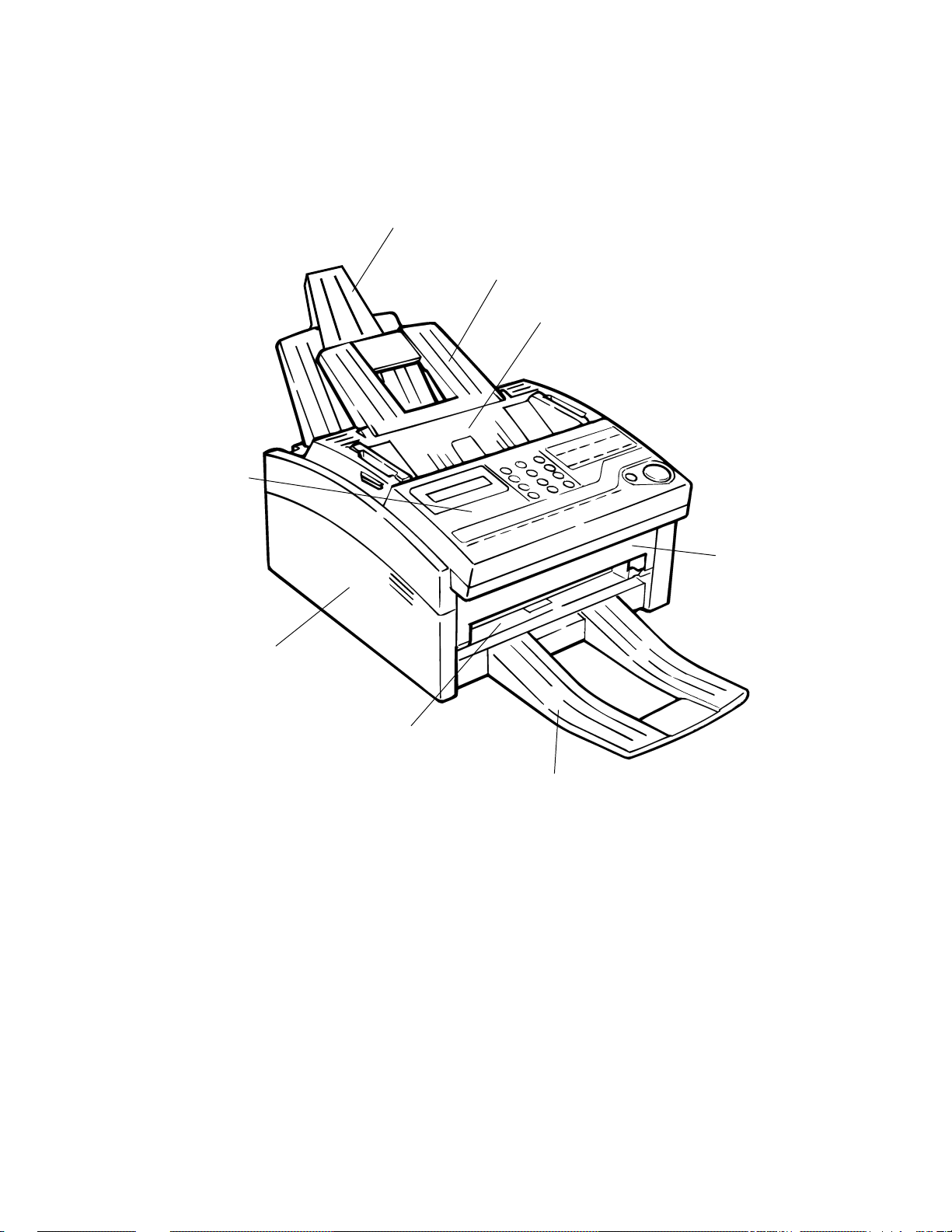
1.4 General Appearance
Figure 1.4.1 shows the general appearance of the OKIOFFICE 44
Case-OPE (T)
Tray-Paper
Tray-Document
Cover-Top
Cover-Main
Cover Manual Document
Stacker-Document (O
Figure 1.4.1 General Appearance of OKIOFFICE44
Cover-Front
tional)
(FX048 CP4.1 Fig. 01)
General Information 1 - 8 OKIOFFICE 44
Service Manual, P/N 59276801

1.5 Basic Performance Specifications
Table 1.5.1 shows basic performance specifications.
Note: TF: Technical function setting
FP: Function program setting
OT: One-touch key pressed
F: SELECT FUNCTION key pressed
Table 1.5.1 (1/11) Basic Performance Specifications
No. Item Specifications
1 Applicable line
2 Line interface
1) Impedance
2) Sending power level
3) Receiving power level
3 Type of document to be transmitted
1) Width
2) Length
1) Public switched telephone network (PSTN)
2) Private branch exchange (PBX) (OT9+2)
600 ohms balanced
0 dBm to –15 dBm range
(Adjustable in 1 dB steps. TF + 22)
0 dBm to –40 dBm range
Max. 216 mm [8.5 inches] (Letter)
Min. 148 mm [5.83 inches] (ISO A5 size)
Note: Effective reading width is Letter (215 mm/8.46 inches).
Min. 128 mm (5.04 inches)
Max. 356 mm (14 inches)
Long document detection: 356 mm (14 inches) or 60 minutes
* TF + 11 (To enable or disable the long document scanning)
An operator can turn the long document scanning feature on or off
for each call in the operating sequence.
3) Thickness
4) Shape
5) Opacity
General Information 1 - 9 OKIOFFICE 44
Based on common bond paper,
a) Multiple Page Feeding
0.08 to 0.13 mm (0.003 to 0.005 inches)
b) Single Page Feeding
0.06 to 0.15 mm (.002 to .006 inches)
Rectangular
Documents allowing less than 40% of the scanner source light to
pass through them.
Service Manual, P/N 59276801

Table 1.5.1 (2/11) Basic Performance Specifications
No. Item Specifications
4 Effective reading width
Document Width
ISO A4
210 mm
8.27 inches
Letter
216 mm
8.5 inches
Legal
216 mm
8.5 inches
Note Local copy: Printable reading width in local copy mode
5 Automatic document feeder (ADF)
Communication
Mode/Paper width
G3/A4
G3/A4
G3/A4
7.87 inches
Effective reading
width
TX: 208 mm
8.19 inches
Local Copy: 200 mm
7.87 inches
TX: 215 mm
8.46 inches
Local Copy: 200 mm
7.87 inches
TX: 215 mm
8.46 inches
Local Copy: 200 mm
Up to 297 mm (11.69 inches) in length.
Maximum of. 20 documents, Letter or A4 (20-1b)
Maximum of 15 documents: Letter or A4 (13-28lb bond paper)
Documents shall be placed facedown on ADF stacker.
The first sheet will be fed first in the feeder and will exit
facedown in the document stacker.
Copy size
A4
Letter
Legal
6 Document skew
7 Document jam detection
8 Document jam removal
General Information 1 - 10 OKIOFFICE 44
Max. 2.6 mm (.102 inches) skew over a document of A4 length.
For a document longer than A4 length, occurrence of skew
exceeding 2.6 mm over any A4 length is 0.5% or less.
1) Transmission will stop and line disconnection will occur
when the end of a document is not detected within 356 mm
(14 inches) after scanning begins (except for the long document scanning. Technical Function 11)
2) A jam will also be declared if the document does not reach
the scanning position within 10 seconds after the start of a
document feed.
Note: When a jam is detected during message transmission
from the feeder, the machine will stop scanning and
disconnect the line, but its receiving capability will
remain valid.
Manual release
Service Manual, P/N 59276801

Table 1.5.1 (3/11) Basic Performance Specifications
No. Item Specifications
9 Recording paper or sheet
NOTE:
For best results, use Okidata recommended papers
Xerox 4200 (20 lb/base weight paper)
Paper approved for xerographic (copier/laser)
printing process
Automatic Feed
1) Type: Plain paper cut (Bond paper)
2) Size: A4: 210 x 297 millimeters
8.27 x 11.69 inches
Letter: 215.9 x 279.4 millimeters
8.5 x 11 inches
Legal: 215.9 x 355.6 millimeters
8.5 x 14 inches
3) Weight: 16 lbs to 24 lbs/base weight
Base weight is defined as the weight of 500 sheets
of 431.8 mm (17 inch) by 558.8 mm (22 inch).
4) Thickness:0.08 mm to 0.12 mm
.0031 inches to .0047 inches
5) Condition: New paper
Manual Feed
Note: One single sheet only should be loaded on the manual
loading feeder for any one occasion.
10 Recording paper cassette
1) Type: Plain paper, transparency for overhead projector,
colored paper, printed paper
Must meet specifications for xerographic printing
process
2) Size: A4: 210 x 297 millimeters
8.27 x 11.69 inches
Letter: 215.9 x 279.4 millimeters
8.5 x 11 inches
Legal: 215.9 x 355.6 millimeters
8.5 x 14 inches
3) Weight: 16 lbs to 24 lbs/base weight
Base weight is defined as the weight of 500 sheets
of 431.8 mm (17 inch) by 558.8 mm (22 inch).
4) Thickness:0.08 mm to 0.12 mm
.0031 inches to .0047 inches
100 sheets/tray (20 lb.)
General Information 1 - 11 OKIOFFICE 44
Service Manual, P/N 59276801
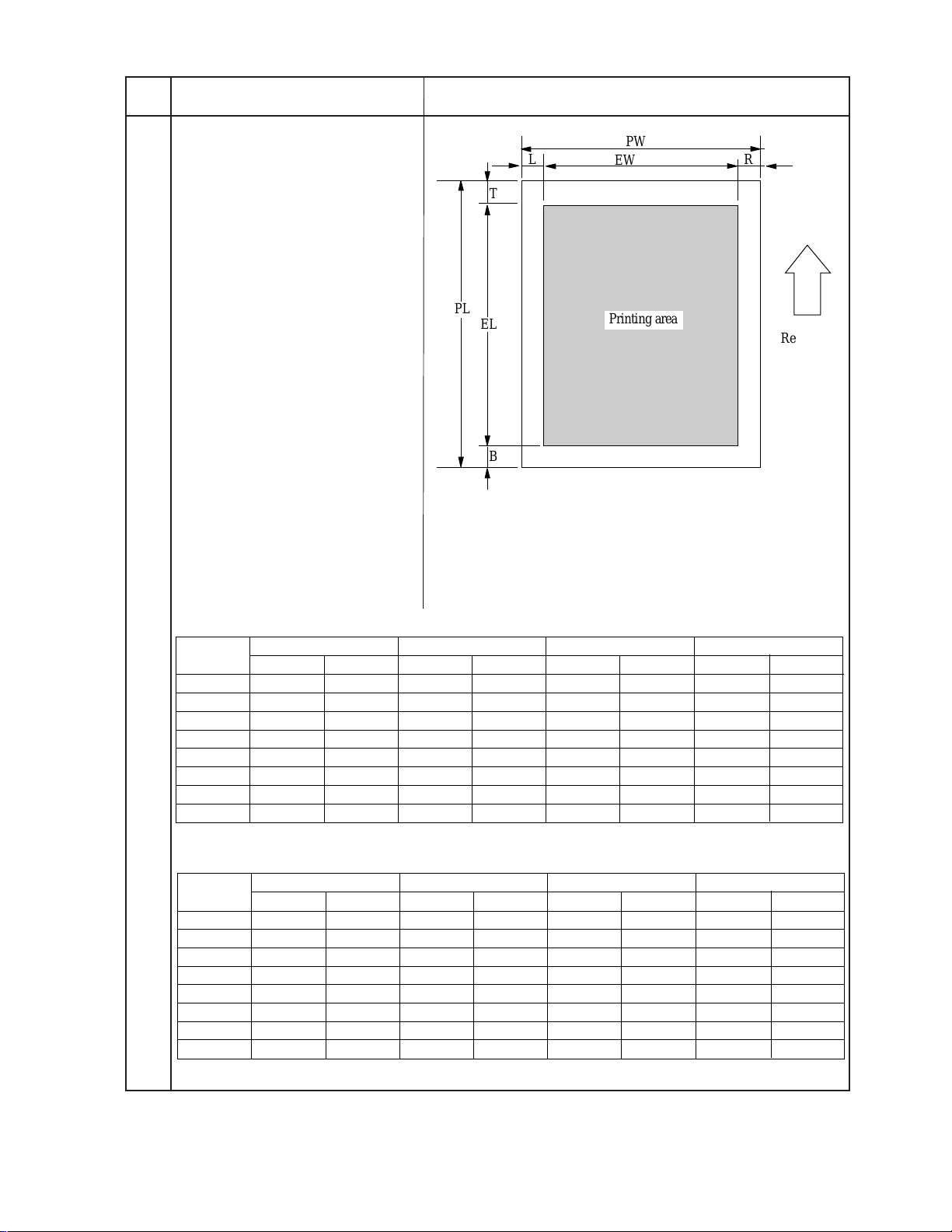
Table 1.5.1 (4/11) Basic Performance Specifications
Printing area
EL
PL
B
T
L
R
PW
EW
Recording
paper
feed
direction
(F050-C1-001)
No. Item Specifications
11 Effective recording area
PL = Page Length
PW = Page Width
EL = Effective Length
EW = Effective Width
T = Top Margin
B = Bottom Margin
L = Left Margin
R = Right Margin
U
¦
Note: These tables do not
include vertical and horizontal addressing deviations
(+ or –2 mm) of recording
paper.
1) Printable area
NA LETTER SIZE ISO A4 SIZE 14 inch LEGAL SIZE
inch mm inch mm inch mm
PL 11 279.4 11.7 297 14 355.6
PW 8.5 216 8.27 210 8.5 216
EL 10.76 273.4 11.46 291 13.76 349.6
EW 8.0 203.2 8.0 203.2 8.0 203.2
T 0.12 3 0.12 3 0.12 3
B 0.12 3 0.12 3 0.12 3
L 0.25 6.35 0.13 3.4 0.25 6.35
R 0.25 6.35 0.13 3.4 0.25 6.35
13 inch LEGAL SIZE
inch
13
8.5
12.76
8.0
0.12
0.12
0.25
0.25
mm
330.2
216
324.2
203.2
3
3
6.35
6.35
2) Guaranteed printing area
PL 11 279.4 11.7 297 14 355.6
PW 8.5 216 8.27 210 8.5 216
EL 10.5 266.7 11.2 284.3 13.5 342.9
EW 8.0 203.2 7.77 197.3 8.0 203.2
T 0.25 6.35 0.25 6.35 0.25 6.35
B 0.25 6.35 0.25 6.35 0.25 6.35
L 0.25 6.35 0.25 6.35 0.25 6.35
R 0.25 6.35 0.25 6.35 0.25 6.35
NA LETTER SIZE ISO A4 SIZE 14 inch LEGAL SIZE
inch mm inch mm inch mm
13 inch LEGAL SIZE
inch
13
8.5
12.5
8.0
0.25
0.25
0.25
0.25
mm
330.2
216
317.5
203.2
6.35
6.35
6.35
6.35
General Information 1 - 12 OKIOFFICE 44
Service Manual, P/N 59276801

Table 1.5.1 (5/11) Basic Performance Specifications
No. Item Specifications
12 Copy stacking
13 Scanning resolution
14 Image scanning method
15 Contrast control
The fax can discharge printed copies and stack them faceup.
Maximum sheets on the copy stacker: 30*
Note*: Oki Data recommended paper
Horizontal:
• 8 pel/mm
Vertical:
Transmission mode:
• STD 3.85 line/mm
FINE 7.7 line/mm
EX.FINE 15.4 line/mm
COPY mode:
FINE: 7.7 line/mm
EXFINE 15.4 line/mm
Letter size (1728-bit) contact image sensor
1) Automatic background sensing
A continuous document background of 0.3 OD (optical density)
or less will be transmitted as white.
2) The LIGHT and DARK contrasts will automatically be adjusted to improve image quality.
16 Recording resolution
17 Recording system
18 Skew of recording paper
19 Copy darkness
20 Copy uniformity
Horizontal:
• 300 dot/inch
Vertical:
• STD: 3.85 line/mm
FINE: 7.7 line/mm
Electro-photographic printing
1) 211.3mm (2496 bit) or 216.7mm (2560 bit) LED print head
Maximum allowable skew is + or - 1 mm over an advance of 100
mm. (.03937 inches over 3.937 inches)
1) Black image: Greater than 1.0 OD (Optical density)
2) White background: Not greater than 0.2 OD
(Optical density)
Printed copies will exhibit a uniform density of the printed and
background area:
1) From edge to edge: 25% unit
2) From copy to the next copy: 30% unit
General Information 1 - 13 OKIOFFICE 44
Service Manual, P/N 59276801

Table 1.5.1 (6/11) Basic Performance Specifications
No. Item Specifications
21 Recording paper running out
22 Minimum scan line time for receiving
23 Coding scheme
24 MODEM
1) High-speed MODEM
2) Low-speed MODEM
Detected during print operation only.
Error Message:
PAPER OUT / JAM
CONFIRM AND“STOP”
0 ms, when receiving from an Oki Data facsimile.
5 ms at 7.7 line/mm and 10 ms at 3.85 line/mm when receiving from
a non-Oki Data facsimile.
1) One-dimensional coding scheme:
Modified Huffman (MH)
2) Two-dimensional coding scheme:
Modified READ (MR)
Modified modified READ (MMR)
a) ITU-T Rec. V.29 (9600/7200 bps)
b) ITU-T Rec. V.27 ter (4800/2400 bps)
c) ITU-T Rec. V.17 (14400/12000/9600/7200 bps)
d) ITU-T Rec. V.33 (14400/12000 bps)
ITU-T Rec. V.21 channel 2 (300 bps)
General Information 1 - 14 OKIOFFICE 44
Service Manual, P/N 59276801
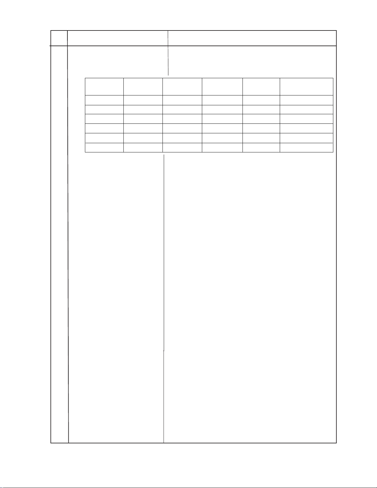
Table 1.5.1 (7/11) Basic Performance Specifications
No. Item Specifications
25 Fallback
26 Protocol
Fallback
rank
1st
2nd
3rd
4th
5th
6th
Transmission
speed
14400 bps
12000 bps
9600 bps
7200 bps
4800 bps
2400 bps
Automatic fallback will occur according to the following sequence
by FTT, RTN or PPR.
Activated by
FTT (Times)
1
1
1
1
2
2
Activated by
RTN (Times)
1
1
1
1
1
1
Activated by
PPR (Times)
4 (Note 1)
4 (Note 1)
4 (Note 1)
4 (Note 1)
4 (Note 1)
4 (Note 1)
Protocol
ITU-T V.17 (V.33)
ITU-T V.17 (V.33)
ITU-T V.17 (V.29)
ITU-T V.17 (V.29)
ITU-T V.27 ter.
ITU-T V.27 ter.
When the last trial fails, the transmitting station sends out a DCN
signal to the remote station for disconnection.
Note: Continuous PPRs for the same partial page within each
fallback rank.
1) ITU-T Rec. T.30
2) Oki Data special protocol
High-speed protocol
The T.30 protocol signal from the transmitting station is sent at
message transmission speed instead of 300 bps.
Note: In high-speed protocol, 28.8 K-bps are not supported.
27 Transmission time
28 Error correction
29 Communication mode
30 Ringing signal detection sensitivity
1) Voltage range
2) Frequency range
3) Ring response time
6 sec. /ITU-T No. 1 sample document
Note: This is Phase C time at 3.85 line/mm and 14400 bps for 6
sec. in MMR code transmission.
ITU-T Error correction mode (ECM)
Oki Data ITU-T ECM
Half-duplex
25 to 150 V r.m.s.
Inoperative below 10 V
20 to 68 Hz
One-ringing signal or 5 to 30 seconds.
(Selectable in 5 sec. steps. F + OT9 + ← + 11)
General Information 1 - 15 OKIOFFICE 44
Service Manual, P/N 59276801
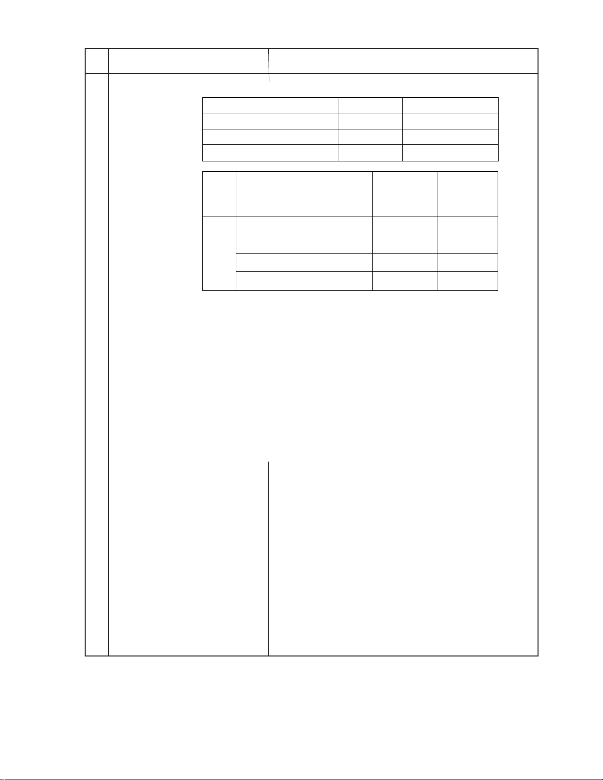
Table 1.5.1 (8/11) Basic Performance Specifications
No. Item Specifications
31 Image memory
OKIOFFICE44
Memory
condition
Standard
With
option
board
(without option)
1M-byte
2M-byte
Basic model
256K-byte
20
100
N/A
Optional memory
1M-byte
Note: ITU-T No.1 sample document is used to count the number
of sheets.
Back-up time on electrical interruption:
Note: OKIOFFICE44 does not back up the message received in
memory for the power failure.
32 Telephone handset
(option)
34 Overheat protection
35 PC interface applications (Option)
Note: This function is standard
for OKIOFFICE44.
General telephone function is available while the power is on.
Note: In the fax special versions, general telephone is available
even when the power is off.
The heater of the fuser unit is controlled within the predetermined
temperature range by the thermistor. If the temperature of the
heater exceeds the range, the LCD displays “PRINTER ALARM
4”.
Furthermore, the built-in thermostat in the fuser unit prevents the
heater from being overheated even in the event of the failures in the
above temperature control circuit.
The following four modes are supported:
1) PC local printer function
2) PC scanner function
3) PC FaxModem function
4) Location Programing function
General Information 1 - 16 OKIOFFICE 44
Service Manual, P/N 59276801

Table 1.5.1 (9/11) Basic Performance Specifications
t cannot be enabled or disabled by the user.
No. Item Specifications
36 Power supply unit and power consump-
tion of the machine
Power consumption of the machine
(Typical power)
Transmit
Receive
Local copy
Standby
** Power save mode is automatic for the OKIOFFICE 44.
OKIOFFICE44
19W
115W
150W
10W
I
General Information 1 - 17 OKIOFFICE 44
Service Manual, P/N 59276801

Table 1.5.1 (10/11) Basic Performance Specifications
No. Item Specifications
37 Ambient condition
See Figure 1.5.1
1) Operating condition
See Figure 1.5.1
2) Storage condition
Figure 1.5.1
Temperature and Humidity Conditions (Figure 1.5.1 Ambient Conditions)
90
85%
28°C85%
80
73%
70
0°C64%
60
50
40
30
20
Relative humidity [%RH]
0°C10%
10
0
Area enclosed by lines with : Range where printing is guaranteed.
Area enclosed by lines with : Range for storage without power supply.
18°C80%
10°C73%
10°C30%
15°C20%
18°C
10 20 30 40
15°C
TEMPERATURE [°C]
27°C80%
32°C54%
32°C20%
28°C
27°C
43°C29%
43°C10%
43°C
(Note) The curve connecting 28°C, 85% and 0°C, 64%
is the condensation curve.
General Information 1 - 18 OKIOFFICE 44
Service Manual, P/N 59276801

Table 1.5.1 (11/11) Basic Performance Specifications
No. Item Specifications
38 Dimension
(Main body)
39 Weight
(Main body)
40 Attachments
(to the main body)
1) Width: Approx. 312 mm (12.28 inches)
2) Depth: Approx. 383 mm (15.08 inches)
3) Height: Approx. 190 mm (7.48 inches)
Approx. 8 kg (17.6 lbs)
Excluding optional units, recording paper and packing
materials.
1) AC power cord x 1
2) I/D unit x 1 (Already installed)
3) Toner cartridge x 1
4) Telephone handset x 1 (option)
5) Curled cord and Telephone cord for (4) x 1 (option)
6) Document stacker x 1
7) Line cord x 1
8) One touch sheet x 1 (Already installed)
9) User’s guide x 1
10) JetSuite Software User Guide x 1
11) Quick Start Guide x 1
12) WordScan OCR Manual x 1
General Information 1 - 19 OKIOFFICE 44
Service Manual, P/N 59276801

1.6 Reports and Lists
Table 1.6.1 shows Reports and Lists Specifications.
Note: F +OT: Press FUNCTION and One-touch key
FP: Function program setting
TF: Technical function setting
Table 1.6.1 (1/2) Reports and Lists Specifications
No. Item Specifications
1 Call-back message
2 Sender ID
3 Transmitting subscriber identifica-
tion (TSI) printing
4 Cancel report
(Power outage report)
5 Activity report
6 Message confirmation report
The transmitter sends a call-back message to the receiver only
when the receiver does not respond to voice request of the transmitter.
The fax can transmit a programmed alphanumeric message, such as
company’s name, consisting of up to 32 characters.
This is an FCC Requirement in the United States
* (Outside only)
Received TSI can be printed at the top of the received page.
* TF + 05 (To enable or disable this function)
The fax can automatically print out a power-outage report when the
power off condition occurs.
The fax can print out an activity report manually, or automatically,
when 30 communications are recorded.
* REPORT PRINTOUT+1 (Manual printout)
The fax can print out a message confirmation report manually or
automatically in the following cases.
(1) When COPY key is pressed after a single location
call, this report can be printed.
(Manual printout)
* FP + 01 (To enable or disable automatic printing)
7 Broadcast entry report
8 Broadcast confirmation report
General Information 1 - 20 OKIOFFICE 44
The fax can print out a broadcast entry report if specified during
operating sequence of a broadcast.
The fax can print out a broadcast confirmation report manually or
automatically.
* COPY key (Manual printout): Pressed after a broadcast.
* REPORT PRINTOUT + 2 (Manual printout)
* FP +02 (To enable or disable automatic printing)
Service Manual, P/N 59276801

Table 1.6.1 (2/2) Reports and Lists Specifications
No. Item Specifications
9 Confidential reception report
10 Telephone directory
11 Configuration report
The fax can print out this report automatically on completion of a
confidential reception.
This directory is printed manually.
(REPORT PRINTING +3)
This report is printed manually.
(REPORT PRINTING +4)
General Information 1 - 21 OKIOFFICE 44
Service Manual, P/N 59276801

Call-back Message Format: (Example)
(1) (2)
07/01/96
(4)
(5)
(6)
(1) Date and time
(2) Sender ID
(3) CSI/Personal ID
(4) Letters "PLEASE CALL BACK"
(5) Sender ID
(6) Sender's call back telephone number
09:24 OKI SHIBAURA → OKI HONJO
PLEASE CALL BACK
OKI SHIBAURA
=103 5476 1234
Sender ID Format: (Example)
(3)
NO.002
(F050-C1-002)
(1)
07/01/96 15:06 OKI ABC 1234 → 3454 2000 NO.021 01
(1)
Date and Time
(2)
Sender ID
(2) (3)
(4) (5)
~~
(3)
Receiver's CSI/Personal ID
Session number
(4)
(5)
Page number
(F050-C1-003)
General Information 1 - 22 OKIOFFICE 44
Service Manual, P/N 59276801

TSI Printing and Local Date and Time Printing Format: (Example)
07/01/96 15:48 3454 1999
TSI printing
~~
Note: TSI printing (TF+05)
Local date and time printing
(F050-C1-004)
Local date and time printing (TF+04)
General Information 1 - 23 OKIOFFICE 44
Service Manual, P/N 59276801

This page was intentionally left blank.
General Information 1 - 24 OKIOFFICE 44
Service Manual, P/N 59276801

Cancel Report Format: (Example)
POWER OUTAGE REPORT
05/19/96 17:05
ID=OKI
DATE TIME S,R-TIME DISTANT STATION ID MODE PAGES RESULT
05/17 10:10 0485-88-3385 9080
05/17 10:30 ODS TAKASAKI 03 0000
05/17 12:05 01'20" OKI FAX BOX=01 03 OK 0000
05/17 13:00 00'20" 03-5476-4300 CALLED 01 OK 0000
05/17 15:40 034567092222 FWD-T 05
05/18 10:50 01'20" 0495-22-5400 CALLED 03 OK 0000
05/18 15:00 B.C. 01
Note: Memory reception only is printed on the mode in the report as called.
General Information 1 - 25 OKIOFFICE 44
Service Manual, P/N 59276801

(1)
Message Confirmation Report Format: (Example)
ACTIVITY REPORT
(2)
05/19/96 17:05
(3)
ID=OKI
(4)
TOTAL TIME CALLING=08:22' CALLED=17:30'
DATE TIME S,R-TIME DISTANT STATION ID MODE PAGES RESULT
(5) (6) (7) (8) (9) (10) (11) (12)
05/17 10:00 01'20" OKI FAX CALLING 02 OK 0000
05/17 10:10 01'00" 0485 88 3385 CALLING 00 STOP 9080
05/17 10:30 00'20" ODS TAKASAKI CALLING 00 NO 90C1
05/17 12:05 01'20" OKI FAX CALLING 03 OK 0000
05/17 13:00 00'20" 03 5476 4300 CALLING 01 OK 0000
05/17 15:40 03'25" ODS TAKASAKI BOX=01 03 OK 0000
05/17 19:00 00'00" OKI FAX 01 OK 0000
05/18 10:10 02'00" OKI SHIBAURA CALLED 05 NO 908E
05/18 10:22 00'12" 0495 22 5400 CALLING 00 STOP 9080
05/18 10:50 01'20" 0495 22 5400 CALLED 03 NO 9090
05/18 12:05 00'20" OKI FAX CALLING 01 STOP 9080
05/18 15:00 01'30" CALLED 03 OK 0000
05/18 15:30 00'20" CALLING 01 OK 0000
05/18 17:05 05'20" B.C. COMP. 60A0
05/18 19:04 00'20" 03 5476 4300 CALLING 00 STOP 9080
05/19 09:00 01'11" CALLING 02 OK 0000
05/19 10:20 00'20" 03 5476 4300 CALLING 02 STOP 9080
05/19 10:35 02'23" BOX=01 02 OK 0000
05/19 10:50 00'20" ODS TAKASAKI CALLED 01 OK 0000
05/19 11:03 00'00" OKI FAX CALLING 00 STOP 9080
05/19 13:00 00'24" 03 5476 4300 01 NO 0000
05/19 16:00 03'25" ODS TAKASAKI FWD-R 03 OK 0000
05/19 16:04 03'30" OKIFAX FWD-T 03 OK 0000
*1
*2
*3
*4
*1
*5
*6
*7
*1 : Confidential reception
*2 : Manual TX
*3 : Memory reception
*4 : Broadcast TX
*5 : Manual reception
*6 : Reception for forwarding
*7 : Forwarding
General Information 1 - 26 OKIOFFICE 44
Service Manual, P/N 59276801

(1) Title of the report
(2) Date and time when the report was printed
(3) Sender ID
(4) Total CALLING and CALLED time
(5) Date of transmission or reception
(6) Time when the communication started
(7) Time span of the fax communication.
(8) Identification of the remote station
Personal ID/Location ID/TSI/CSI/Dial number or space
(9) Communication mode:
CALLING (Transmission)
CALLED (Reception NG or MEMORY RX)
B. C. (Broadcast)
BOX=XX (Confidential reception)
FWD-R (Fax Forwarding RX)
FWD-T (Fax Forwarding TX)
(10) Number of transmitted pages or received pages
(11) Result code
OK (Note1)/NO/STOP (Note 2)/BUSY/PAPER (Out of recording paper)/S_JAM (Document
jam)/R_JAM (Recording paper jam)/COVER/COMP (Completion of a broadcast)/PUNIT
(Printer Alarm)/CANCL (Confidential reception T.O.)
Note 1: The following cases are included:
• Unmatched handshaking to the received NSF.
• Unmatched password to the received NSC in the polling transmission mode.
Note 2: The following cases are included:
• The STOP key is pressed.
• The memory cancellation operation removes the message from the active memory files.
(12) Service code
(Rev.2)
General Information 1 - 27 OKIOFFICE 44
Service Manual, P/N 59276801

Message Confirmation Report Format (1/2): (Example)
(1)
MESSAGE CONFIRMATION
(2) 07/01/96 08:05
(3) ID=OKI
DATE S.R-TIME DISTANT STATION ID MODE PAGES RESULT
(5) (6) (7) (8) (9) (10)(4)
OKI FAX00'20"07/01 CALLING 02 OK 0000
(F050-C1-008 1/2)
General Information 1 - 28 OKIOFFICE 44
Service Manual, P/N 59276801

Message Confirmation Report Format (2/2): (Example)
(1)
MESSAGE CONFIRMATION
(2) 07/01/96 17:05
(3) ID=OKI
DATE S.R-TIME DISTANT STATION ID MODE PAGES RESULT
(5) (6) (7) (8) (9) (10)(4)
OKI FAX00'20"07/01 B.C. 01 COMP 60A0
OKI OKIFAX17:0007/01/96 No.022 001
150 km
(11)
(F050-C1-008 2/2)
(1) Title of the report
(2) Date and time when the report was printed
(3) Sender ID
(4) Date of transmission or reception
(5) Length of time for which the fax was connected to the line
(6) Identification of the remote station
Personal ID/Location ID/TSI/CSI/Dial number
(7) Communication mode
Reference to ACTIVITY REPORT
(8) Number of transmitted pages or received pages
(9) Result of the communication
Reference to ACTIVITY REPORT
(10) Service code
(11) Message
General Information 1 - 29 OKIOFFICE 44
Service Manual, P/N 59276801

Broadcast Entry Report Format: (Example)
BROADCAST ENTRY REPORT
07/01/96 17:05
ID=OKI
LOCATION ID LOCATION ID LOCATION ID
ONE TOUCH
1 = OT1 2 = OT2 3 = OT3
4 = OT4 5 = OT5 6 = OT6
7 = OT7 8 = OT8 9 = OT9
10 = OT10 *1 11 = OT11 12 = OT12
13 = OT13 14 = OT14 15 = OT15 *2
16 = OT16 17 = OT17 18 = OT18
19 = OT19 20 = OT20 21 = OT21
22 = OT22 23 = OT23 24 = OT24
25 = OT25 26 = OT26 27 = OT27
28 = OT28 29 = OT29 30 = OT30 *3
AUTO DIAL
01 = AD1 02 = AD2 03 = AD3
04 = AD4 05 = AD5 06 = AD6
07 = AD7 08 = AD8 09 = AD9
10 = AD10 11 = AD11 12 = AD12
13 = AD13 14 = AD14 15 = AD15
16 = AD16 17 = AD17 18 = AD18
19 = AD19 20 = AD20 21 = AD21
22 = AD22 23 = AD23 24 = AD24
25 = AD25 26 = AD26 27 = AD27
28 = AD28 29 = AD29 30 = AD30
31 = 31 32 = 32 33 = 33
34 = 34 35 = 35 36 = 36
37 = 37 38 = 38 39 = 39
40 = 40 41 = 41 42 = 42
43 = 43 44 = 44 45 = 45 *1
46 = 46 47 = 47 48 = 48
49 = 49 50 = 50 51 = 51
52 = 52 53 = 53 54 = 54
55 = 55 56 = 56 57 = 57
58 = 58 59 = 59 60 = 60
61 = 61 62 = 62 63 = 63
64 = 64 *2 65 = 65 66 = 66
67 = 67 68 = 68 69 = 69
70 = 70 71 = 71 72 = 72
73 = 73 74 = 74 75 = 75
76 = 76 77 = 77 78 = 78
79 = 79 80 = 80 81 = 81
82 = 82 83 = 83 84 = 84
85 = 85 86 = 86 87 = 87
88 = 88 89 = 89 90 = 90
91 = 91 92 = 92 93 = 93
94 = 94 95 = 95 96 = 96
97 = 97 98 = 98 99 = 99
KEYPAD
1234
2345
3456
4567
*1 FX-480 : 10 45 1
*2 FX-050VP: 15 64 5
*3 FX-175VP: 30 99 5
MAX.
OT AD KEYPAD
General Information 1 - 30 OKIOFFICE 44
Service Manual, P/N 59276801

Broadcast Confirmation Report Format: (Example)
BROADCAST CONFIRMATION REPORT
PAGES = 01
TOTAL TIME = 00:02'30"
07/01/96 17:05
ID=OKI
ONE TOUCH
1 = OT1
3 = OT3
5 = OT5
AUTO DIL
01 = AD1
03 = AD3
05 = AD5
KEYPAD
LOCATION ID PAGES RESULT
1234
3456
5678
01
01
01
01
01
01
01
01
01
OK
OK
OK
OK
OK
OK
OK
OK
OK
Confidential Reception Report Format: (Example)
LOCATION ID PAGES RESULT
2 = OT2
4 = OT4
02 = AD2
04 = GERMAN
0101OK
OK
0101OK
OK
(F030-C1-010)
CONFIDENTIAL RX REPORT
07/01/96 17:05
ID=OKI
DATE TIME S,R-TIME DISTANT STATION ID MODE PAGES RESULT
07/01 00:20 00'00" OKI FAX BOX=01 02 OK 0000
General Information 1 - 31 OKIOFFICE 44
Service Manual, P/N 59276801

Telephone Directory for OKIOFFICE 44 (1/2): (Example)
TELEPHONE DIRECTORY P1
07/01/96 19:19
ID=OKI DATA CORP.
ONE TOUCH
AUTO DIAL
LOCATION ID TEL NO. PRM. ECHO
1 OKI SERVICE 123 123 123 (OFF)
OR 111 222 333
2 OKI OFFICE 456 456 456 (OFF)
OR 444 555 666
3 OKI LABORATORY 789 789 789 (OFF)
OR 777 888 999
4 ODC TAKASAKI 000 111 222 (OFF)
OR 444 555 666
5 ODC QA/QC LAB. 1234 5678 90123 (OFF)
OR 123 123 123
6 (OFF)
OR
7 (OFF)
OR
8 (OFF)
OR
9 (OFF)
OR
10 (OFF)
OR
01
02
03
04
05
06
07 ODC TAKASAKI 0273 28 1234
08
09
10
11
12
13
14
15
16
17
18
19
20
21
22
23
24
25
26
27
28
29
30
31
32
33
34
35
36
37
38
39
40
41
42
43
44
45
General Information 1 - 32 OKIOFFICE 44
Service Manual, P/N 59276801

Telephone Directory for OKIOFFICE 44 (2/2): (Example)
TELEPHONE DIRECTORY P2
GROUP NUMBER = #1 #2 #3 #4 #5
#1 ONE TOUCH
1 2 3 4 5 6 7 8 9 10
AUTO DIAL
01 02 03 04 05 06 07 08 09 10 11 12 13 14 15 16 17 18 19 20 21 22 23 24 25
26 27 28 29 30 31 32 33
#2 ONE TOUCH
AUTO DIAL
#3 ONE TOUCH
07/01/96 19:20
ID=OKI DATA CORP.
AUTO DIAL
#4 ONE TOUCH
AUTO DIAL
#5 ONE TOUCH
5
AUTO DIAL
07
General Information 1 - 33 OKIOFFICE 44
Service Manual, P/N 59276801

Configuration Report (User)
NOTE:
The function settings shown ARE NOT
the factory defaults.
Refer to Section 2 for the technical function setting defaults.
FUNCTION LIST
01:MCF (SINGLE-LOC.) 02:MCF (MULTI-LOC.) 03:ERR.REPORT (MCF)
ON ON ON
04:MESSAGE IN MCF 05:SENDER ID. 06:MONITOR VOLUME
ON ON LOW
07:BUZZER VOLUME 08:CLOSED NETWORK 09:TX MODE DEFAULT
MIDDLE OFF FINE/NORMAL
10:T/F TIMER PRG. 11:RING RESPONSE 12:DISTINCTIVE RING
35SEC 1RING OFF
13:1'ST PAPER SIZE 14:2'ND PAPER SIZE *1 15:USER LANGUAGE
A4 A4 ENGLISH
16:INCOMING RING 17:REMOTE RECEIVE 18:MEM./FEEDER SWITCH
ON OFF MEMORY
CONFIGURATION
07/01/96 17:05
ID=OKI
19:POWER SAVE MODE 20:ECM FUNCTION 21:REMOTE DIAGNOSIS
ON ON OFF
22:PC/FAX SWITCH *2
ON
TEL NO. = 12345678901234567890
CALL BACK NO. = 12345678901234567890
FORWARD TEL NO. = 12345678901234567890
REDIAL TRIES 3TRY REDIAL INTERVAL 3MIN
DIAL TONE DETECT OFF BUSY TONE DETECT ON
MF(TONE)/DP(PULSE) MF PULSE DIAL RATE 10PPS
PULSE MAKE RATIO 39% PULSE DIAL TYPE NORMAL
MF (TONE) DURATION 100MSEC PBX LINE OFF
PBX TYPE NORMAL AUTO START ON
DIAL PREFIX OFF IT2 DETECT ON *3
*1 Function 14 is printed when 2'nd Tray is installed.
*2 Function No.22 is printed when CTR board is installed.
*3 In case of country code=FRE
General Information 1 - 34 OKIOFFICE 44
Service Manual, P/N 59276801

Service Default Report (Configuration Report: Service bit=ON)
CONFIGURATION
07/01/96 17:05
ID=OKI
FUNCTION LIST
01:SERVICE BIT 02:MONITOR CONT. 03:COUNTRY CODE
ON OFF USA
04:TIME/DATE PRINT 05:TSI PRINT 06 :NO TONER MEM. RX
OFF OFF ON
07:TAD MODE 08:REAL TIME DIAL 09:TEL/FAX SWITCH
TYPE2 TYPE2 ON
10:MDY/DMY. 11:LONG DOC. SCAN 12:TONE FOR ECHO
MDY OFF OFF
13:MH ONLY 14:H/MODEM RATE 15:T1 (TX) TIMER VALUE
OFF 14.4K 59SEC
16:T1 (RX) TIMER VALUE 17:T2 TIMER VALUE 18: DIS BIT32
35 SEC 10 SEC ON
19:ERR. CRITERION VALUE 20:OFF HOOK BYPASS 21:NL EQUALIZER
10 OFF 0DB
22:ATTENUATOR 23:T/F TONE ATT. 24:MF ATT.
10DB 10DB 6DB
25:RING DURA. * 10MS 26:CML TIMING * 100MS 27:LED HEAD STROBE
12 3 10100
28:LED HEAD WIDTH 29:MEDIA TYPE 30:TR LATCH CURRENT
TYPE1 MEDIUM +1
31:SYMBOL RATE
3200
Note: No. 30 is only for FX-048.
No. 31 is only for FX-175VP.
General Information 1 - 35 OKIOFFICE 44
Service Manual, P/N 59276801

This page was intentionally left blank.
General Information 1 - 36 OKIOFFICE 44
Service Manual, P/N 59276801

Section 2: Installation
2.1 General Setup Information
The following flowchart outlines the installation procedure.
Site selection
Unpacking
Check of contents
Installation of attachments
AC cord connection
Telephone and line connections
Packing for shipment
(See 2.2)
(See 2.3)
(See 2.4)
(See 2.5)
(See 2.6)
(See 2.7)
(See 2.8)
General procedure key operations
Technical functions
Technical functions example
User's functions
User's functions example
Clock adjustment
1
(See 2.9.1)
(See 2.9.2)
(See 2.9.3)
(See 2.9.4)
(See 2.9.5)
(See 2.9.6)
• Function Program
• Ring response time
• Dial parameter
(service bit off)
Installation Procedure 2 - 1 OKIOFFICE 44
Service Manual, P/N 59276801

1
System data programming
*
One-touch key programming
*
Two-digit auto dial programming
*
Group setting
Dial parameter settings
*
Programming mail box password
(See 2.9.8)
TSI/sender ID included.
(See 2.9.9)
*
Memory operations
Installation of optional units
* : See user's guide
Off-line tests
On-line tests
(See 2.9.10)
(See 2.9.11)
(See C)
• Memory PC Board
Installation Procedure 2 - 2 OKIOFFICE 44
Service Manual, P/N 59276801

2.2 Site Selection
INSTALLATION
Precautions for Installation
(1) Fluctuation in line voltage
• 120V AC (102V to 127V)
• 230V AC (198V to 264V)
(2) Room temperature
50 to 90 degrees Fahrenheit (10 to 32 degrees Celsius)
(3) Humidity
20 to 80% RH
(4) Operating environment
Pressure: Equivalent to altitude of 2500 m and below.
(5) Exposure
Within five minutes at luminous intensity 2,000 lux (with the stacker cover opened).
(6) Required space for installation
The facsimile requires adequate space for safety and good operability.
(7) Levelness of installation surface
1 degree maximum.
(8) Other requirements
Avoid installing in any of the following places:
• A place exposed to direct sunlight
• A place near a heat source or exposed to vibration
• A dusty place
• A place in the atmosphere of acid gas, or steam etc.,
• A place exposed to quick temperature changes
Installation Procedure 2 - 3 OKIOFFICE 44
Service Manual, P/N 59276801

2.3 Unpacking
2.3.1 Unpacking for OKIOFFICE 44
Procedure
(1) Remove tape on the top of the carton box and open its cover.
External carton box
Packing tape
Carton label
Packing tape
Figure 2.3.1.1 Unpacking Procedure (1)
(2) Take out the accessory box from the carton box.
(See Figure 2.3.1.1)
(3) Take out the machine with plastic wrapper from the box.
FX048-C2-003
Installation Procedure 2 - 4 OKIOFFICE 44
Service Manual, P/N 59276801

External carton box
FX048-C2-004
Figure 2.3.1.1 Unpacking Procedure (2)
Installation Procedure 2 - 5 OKIOFFICE 44
Service Manual, P/N 59276801

2.4 Check of Contents
After having taken out the machine and accompanied accessories from the carton box, check the contents
according to the following list:
Table 2.4.1 Contents List for OKIOFFICE 44
Item No. Name Q'ty Remarks
1 OKIOFFICE 44 1
2 AC power cord 1
3 I/D unit 1 Already installed.
4 Toner cartridge 1
5 Line cord 1
6 One touch sheet 1 Already installed.
7 User's guide 1
8 Tray paper 1
9 Tray document 1
10 JetSuite Software 1
User's Guide
11 Quick Start Guide 1
12 WordScan OCR 1
Manual
Installation Procedure 2 - 6 OKIOFFICE 44
Service Manual, P/N 59276801

2.5 Installation of Attachments
(1) Items
• Image Drum (ID) Unit (already installed)
• Toner cartridge
• Recording paper
• Tray-paper, Tray-document and Document-stacker
(2) Procedure
1) Toner cartridge
• Peel off the fixed tape attached to the cover-top.
• Open the cover-top.
• Take the plastic cover out of the ID unit.
Cover-Top
Figure 2.5.1.1 Toner Cartridge Installation (1)
FX048-C2-006
• Take out the toner cartridge from the damp proof bag, shake it five or six times as shown in the
illustration to eliminate the toner deflection, and peel off the seal gently.
Mold cover
Figure 2.5.1.2 Toner Cartridge Installation (2)
FX048-C2-007
Installation Procedure 2 - 7 OKIOFFICE 44
Service Manual, P/N 59276801
Rev. 2

• Ensure that the plastic tab on the right-hand side of the toner cartridge recess lines up with the
groove on the toner cartridge.
Seal
Toner cartridge
FX048-C2-008
Figure 2.5.1.3 Toner Cartridge Installation (3)
• Press down on both ends to make sure the cartridge is fully seated.
• Push the gray tab forward until it stops.
Toner cartrige
FX048-C2-009
Figure 2.5.1.4 Toner Cartridge Installation (4)
Installation Procedure 2 - 8 OKIOFFICE 44
Service Manual, P/N 59276801

Toner cartrige
Gray tab
FX048-C2-010
Figure 2.5.1.5 Toner Cartridge Installation (5)
• Clean the toner scattered in the vicinity of the toner cartridge using a cloth moistened with cold
water. Do not use hot water. Heat makes the toner adhere to surfaces and will make the toner more
difficult to remove.
• Close the cover assembly-top until the buttons have been locked completely.
Installation Procedure 2 - 9 OKIOFFICE 44
Service Manual, P/N 59276801
Rev. 2

(3) Recording paper
Note: About 100 sheets of the new paper can be set on the tray-paper.
Loading the new paper.
Sheets must not exceed 100 sheets of the new paper on the tray-paper. If excessive sheets are set, it will
cause paper jams.
Tray-paper
New paper (face down): 100 sheets
FX048-C2-012
Figure 2.5.7 Recording Paper Cassette Installation (2)
Installation Procedure 2 - 10 OKIOFFICE 44
Service Manual, P/N 59276801
Rev. 2

(4) Tray-paper, Tray-document and Document-stacker (option)
• Hang the tray-paper, the tray-document and the stacker-document (option) onto hanging position.
Tray-paper
Tray-document
Cover-top
Stacker-document
FX048-C2-013
Figure 2.5.1.7 Document Stacker Installation
Installation Procedure 2 - 11 OKIOFFICE 44
Service Manual, P/N 59276801
Rev. 2

2.6 AC Cord Connection
The power supply is provided as follows.
Nominal input voltage 120V AC (Voltage range 102 to 127V AC)
Nominal input voltage 230V AC (Voltage range 198 to 250 V AC)
Check whether the AC voltage of your input is within the above-mentioned voltage range
Connect the female plug of the AC cord to the machine.
Insert the male plug of the AC cord to the inlet receptacle.
Check that the display shows “(Time)” message indicating the standby mode.
1) For OKIOFFICE 44
AC Inlet
FX048-C2-014
Note:
The OKIOFFICE 44 is NOT equipped
with a AC power switch.
Installation Procedure 2 - 12 OKIOFFICE 44
Service Manual, P/N 59276801

2.7 Telephone and Line Connections
(1) Procedure
• Connect the lines.
1) For OKIOFFICE 44
PSTN or Exchange line
Optional Handset
2.8 Packing for Shipment
CAUTION: When packing the OKIOFFICE 44 for shipment, REMOVE THE IMAGE DRUM AND
TONER FROM THE UNIT AND SHIP SEPARATELY!
Failure to do this will result in damage to the machine.
Optional TAD or Handset
FX048-C2-015
Installation Procedure 2 - 13 OKIOFFICE 44
Service Manual, P/N 59276801

2.9 Initial Settings
2.9.1 General Procedure of Key Operation
Figure 2.9.1 shows the general procedure of key operation.
Installation Procedure 2 - 14 OKIOFFICE 44
Service Manual, P/N 59276801

Key Operation Flowchart
(STNDBY MODE)
F (Press the SELECT FUNCTION key.)
SELECT FUNCTION (OT)
Selection by One-touch key
OT1: DELAYED TX
OT2: BROADCAST/FEEDER TX
OT3: CONFIDENTIAL TX
OT4: RELAY INITIATE TX
OT5: POLLING TX/RX
OT6: REPORT PRINT
OT7: COUNTER DISP (CLEAR)
Clear only with Tech Function Off
*2: User can read no. of counter in LCD but can not clear.
*4: When the service bit is set to "OFF", Funtion NO.11
is bypassed to the next function NO. (some countries)
:Effective if the service bit is "ON".
S
OT8: LOCATION PROGRAM
[Prg. Start date (0-9) and start time (0-9)]
[Enter 2-digit (0-64)]
[Prg. Password 4-digit (0000-9999) & Group No. 2-digit (01-99)]
Selection by YES/NO keys or digit (1 to 5)
Selection by ← key or → key
(Display & Clear)
Selection by OT, A/D, # or SEARCH
OT: ONE TOUCH KEY PRG.
COPY COPY
1: ACTIVITY REPORT
2: BROADCAST MCF.
3: PHONE DIRECTORY
4: CONFIGURATION
S
5: PROTOCOL DUMP
S
LOG. REPORT
DRUM COUNTER
S
S
*2
*2
TONER COUNTER
DRUM (Total) COUNTER
PRINT COUNTER
SCAN COUNTER
1
To technical program
→ key
→ key
→ key
→ key
→ key
→ key
→ key
→ key
→ key
→ key
→ key
2
To OT9 or OT10
A/D: AUTO DIAL KEY PRG.
#: GROUP SETTING
Installation Procedure 2 - 15 OKIOFFICE 44
Service Manual, P/N 59276801

Powered on while holding the
2
SELECT FUNCTION key down.
OT9: USER PROGRAM
Selection by YES/NO keys or digit (1 to 5)
1: FUNCTION PROGRAM
1
2: DIAL PARAMETER
REDIAL TRIES
REDIAL INTERVAL
[0-10 TIMES]
[1-6 MINUTES]
01: MCF. (SIGNLE-LOC.)
02: MCF. (MULTI-LOC.)
03: ERR. REPORT (MCF.)
04: IMAGE IN MCF.
05: SENDER ID
06: MONITOR VOLUME
07: BUZZER VOLUME
08: CLOSED NETWORK
09: TX MODE DEFAULT
10: T/F TIMER PRG.
11: RING RESPONSE *4
12: DISTINCTIVE RING
13: 1'ST PAPER SIZE
14:
15: USER LANGUAGE
16: INCOMING RING
17: REMOTE RECEIVE
18: MEM./FEEDER SW
19:
20: ECM FUNCTION
21: REMOTE DIAGNOSIS
22: PC/FAX SWITCH
23: ONE TOUCH PARAM.
DIAL TONE DETECT
BUSY TONE DETECT
MF (TONE)/DP (PULSE)
PULSE DIAL RATES
S
PULSE MAKE RATIO
PULSE DIAL TYPES
MF (TONE) DURATIONS
PBX LINE
FLASH/EARTH /NORMAL
AUTO START
DIAL PREFIX
[OFF/ON]
[OFF/ON]
[MF/DP]
[10/16/20 PPS]
[33/39%]
[N/10-N/N+1]
[75/85/100 MS]
[OFF/ON]
[Flash/Earth/Normal}
[OFF/ON]
[OFF/Digit(s)]
1
3: CLOCK ADJUSTMENT
4: SYSTEM DATA PRG.
TSI/CSI
SENDER ID
OT10: PRINT OPERATION
SUBST. MSG-PRINT
CALL BACK NO.
PRINTER CLEANING
Installation Procedure 2 - 16 OKIOFFICE 44
Service Manual, P/N 59276801

1
Powered on while holding the
COPY key down.
TECHINICAL PROGRAMMING
Selection by YES/NO keys or digit (1 to 4)
Selection by YES/NO keys or digit (1 to 8)
1: LOCAL TEST
2: TECHCICAL FUNCTION
Selection by YES/NO keys or digit (1 to 3)
3: SYSTEM RESET
1: SELF DIAGNOSIS
2: SENSOR CALIBRATION
3: LED TEST
4: TONE SEND TEST
5: MODEM SEND TEST
6: MODEM REC. TEST
7: MF (TONE) SEND TEST
8: TONE (TEL/FAX) TEST
01: SERVICE BIT
02: MONITOR CONT.
03: COUNTRY CODE
04: TIME/DATE PRINT
05: TSI PRINT
06: NO TONER MEM. RX
07: TAD MODE
08: REAL TIME DIAL
09: TEL/FAX SWITCH
10: MDY/DMY
11: LONG DOC. SCAN
12: TONE FOR ECHO
13: MH ONLY
14: H/MODEM RATE
15: T1 (TX) T.O. VALUE
16: T1 (RX) T.O. VALUE
17: T2 T.O. VALUE *100 MS
18: DIS BIT 32
19: ERR. CRITERION
20: OFF HOOK BYPASS
21: NL EQUALIZER
22: ATTENUATOR
23: T/F TONE ATT.
24: MF ATT.
25: RING DURA. ∗ 10 MS
26: CML TIMING ∗ 100 MS
27: HEAD STROBE
28: HEAD WIDTH
29: MEDIA TYPE
30: TR LATCH CURRENT
31:
1: ALL DATA CLEAR
2: LOCATION DATA CLEAR
3: CONFIG. DATA CLEAR
4: DEFAULT TYPE SET *
* Should be set to "1" for proper operation
Installation Procedure 2 - 17 OKIOFFICE 44
Service Manual, P/N 59276801

2.9.2 Technical Functions
This section explains setting items generally conducted by service personnel, not by users.
Table 2.9.1 shows the initial setting items and their purposes. (The default setting is different by the individual
countries.)
Each item can be accessed by entering the corresponding service number on Technical Function.
The detailed procedures of the initial setting items will be explained on the following pages.
Note 1: S-ON: Effective if the service bit has been set to ON.
FP: Function program setting
TF: Technical function setting
Note 2: The fonts displayed on the LCD operation panel may differ from fonts written this manual.
Installation Procedure 2 - 18 OKIOFFICE 44
Service Manual, P/N 59276801

Service Personnel Initial Settings Table 2.9.1 (1/7)
T.F.
No.
01 Service bit
02 Line monitor control
Item Specifications Default
Switching serviceman/user operation.
ON : Service personnel’s features are available.
OFF : Service personnel’s features are not avail-
able.
To enable or disable the following functions:
• Drum (Total) and toner counter clear
• Protocol dump
• Dial parameters
• etc.
To enable continuous monitoring of phone line for
technical troubleshooting.
FP +06 (To select the loudness of monitoring)
ON : Enable
OFF : Disable
Example:
In case of transmission mode, the monitor
will be available during dialling, but the
monitor will be switched off automatically
after the elapse of specified time (about 5
sec.). However, when TF02 is set to ON,
the monitor is available during communication also.
OFF
OFF
03 Country code
04 Time and date print
05 TSI print
Selecting the following country code:
USA, INT'L, GBR, IRL, NOR, SWE, FIN, DEN,
GER, HUN, TCH, POL, SUI, AUT, BEL, HOL, FRE,
ESP, ITA, GRE, AUS, NZL, SIN, HNG
Enables or disables the function of printing local date
and time at the top of the received page.
OFF/ ONCE/ALL selectable.
Note: • Set at receiver.
Switches the function of printing TSI data from remote fax onto the received pages. TSI is printed at the
leading edge of first reproduced copy. (Set at receiver.)
When TF04 is set to “ALL”, TSI is printed for the all
received pages.
ON : Enable
OFF : Disable
(Reference)
TSI; Transmitting Subscriber Identification
USA
OFF
ON
Installation Procedure 2 - 19 OKIOFFICE 44
Service Manual, P/N 59276801

Service Personnel Initial Settings Table 2.9.1 (2/7)
T.F.
No.
06 No-toner memory reception
07 TAD mode
(For external telephone answering device.)
NOTE:
If the REMOTE RX Function is set to
a value other than OFF, that code can
be used to force FAX RX during TAD
Mode.
Item Specifications Default
Enables or disables the memory reception when the
fax is in no toner condition.
ON : The messages are printed when toner has
been newly supplied or an operator performs the memory operation (OT10).
OFF : The messages are printed in the print mode.
But print quality is not guaranteed.
Allows the OKIOFFICE to share a telephone line
with an answering device.
TAD mode is of two types (TYPE1/TYPE2).
OFF/TYPE1/TYPE2 selectable.
TYPE1 means:
1. RING comes.
2. The TAD answers, returns the recorded voice
message in TAD to calling party.
3. The FAX machine will continue to detect CNG
signal while TAD works.
4. If the FAX machine detects CNG signal, the fax
will go into normal receiving mode.
5. Even though the fax does not detect CNG signal,
the fax will go to receiving mode in hook-on
condition.
OFF
TYPE 2
08 Real time dialing
09 TEL/FAX switching
TYPE2 means:
The function from No. 1 to No. 4 of upper TYPE2 are
the same as TYPE1.
5. If the fax does not detect CNG signal during
working of TAD, the machine will go to standby
mode.
Enables or disables the real time dialling.
3 types selectable. (OFF/TYPE1/TYPE2)
TYPE1: Real-time dialling is available when the
optional telephone handset is OFF-HOOK.
TYPE2: Real-time dialling is available when the
optional telephone handset is OFF-HOOK
or HOOK key is pressed.
Enables or disables the TEl/FAX automatic switching.
ON : Enable
OFF : Disable
(Related item: FP10, TF23)
TYPE 2
ON
Installation Procedure 2 - 20 OKIOFFICE 44
Service Manual, P/N 59276801

Service Personnel Initial Settings Table 2.9.1 (3/7)
T.F.
No.
10 MDY/DMY
11 Long document SCAN
12 Echo Protection
Item Specifications Default
Switches LCD display and report print from month/
day/year to day/month/year or vice versa.
MDY/DMY selectable.
Switches the function of transmitting long-size document (more than 380 mm).
ON : Unlimited (1 hour)
OFF : 380 mm. (14.96 inches)
Enables echo suppression for poor lines with echo,
usually during overseas transmissions. This bit setting controls the following features.
ON: Enables
Echo Protection
Ignore 1st DIS
CED-DIS timer
Tone for echo
OFF
OFF
75 ms
OFF
ON
ON
1.5 sec
ON
MDY
OFF
OFF
13 MH only
14 High-speed modem rate
15 T1 (TX), timeout value
(TF-12 table)
OFF: Disables
Switches the function of limiting image compression
only to the MH codes.
ON : Coding scheme is MH only. When the
receiving image data is affected by noise on
the telephone line.
This affects all communications and should
only be used as a last resort.
OFF : Any of MH, MR and MMR.
Specifies the modem’s starting speed, 14.4k, 9.6k, or
4.8kbps.
Registers the time duration (in seconds) for which the
fax waits for the remote station’s answer.
This timer starts when the last dialled digit has been
sent in the automatic transmission mode.
* Selects the 3 digit timer
010 to 255 sec selectable (in one second steps).
OFF
14.4 k
059 sec
Installation Procedure 2 - 21 OKIOFFICE 44
Service Manual, P/N 59276801

Service Personnel Initial Settings Table 2.9.1 (4/7)
T.F.
No.
16 T1 (RX), timeout value
17 T2, timeout value
18 DIS bit 32
Item Specifications Default
T1 (RX), timeout value (later)
Registers the time duration (in seconds) for which the
fax waits for the remote station’s answer. This timer
starts after the DIS is transmitted, and checked this
timer by the transmission timing signal. If T1 times
out, the fax disconnects the line.
* Selects the 3 digit timer
010 to 255 sec selectable. (in one second steps)
T2, timeout value (layer)
Registers the time duration (in seconds) for which the
fax detects the EOL interval during reception of
phase C. The fax disconnects the line when EOL can
not detect within T2 timer.
* Selects the 3 digit timer
001 to 255 selectable. (in 100 ms steps)
For example: 060 x 100 ms =6 s
Specifies whether to transmit a bit 32 in DIS.
035 sec.
130 sec.
ON
19 Error criterion
20 Off-hook bypass
21 NL equalizer
ON : Transmits a bit 32
OFF: Disable
Note: Disable only if communication/compat-
ibility problems occur with older remote
machine.
Registers the threshold value whether to transmit
RTN or MCF signal when the error occurs in received
data.
00% to 99% selectable. (in one percent steps)
Allows two OKIFAX machines to be connected
back-to-back for testing purposes.
ON : Enable
OFF: Disable
Selects equalization for the following cable lengths:
0 km/1.8 km/3.6 km/ 7.2 km selectable.
Note: Relative to 1700 Hz for length of 0.4 mm
diameter cable.
10%
OFF
0 Km
Installation Procedure 2 - 22 OKIOFFICE 44
Service Manual, P/N 59276801

Service Personnel Initial Settings Table 2.9.1 (5/7)
T.F.
No.
22 Modem attenuator
23 T/F tone attenuator
(for TEL/FAX SW)
Item Specifications Default
Adjusts the attenuation (dB) for the transmit signal
power level.
Adjusting value is 0 to 15 dB in one dB steps.
Since the maximum send signal power level (dB) of
the fax is at 0 dB, you can select 0 dB to -15 dB in one
dB steps for the send signal power level.
0 to 15 dB. selectable
Note: The send signal power level should meet
your country’s regulation. Some countries
may specify the power level at a telephone
exchange.
In that case, you should subtract the specified level from the line cable attenuation to
determine the send level of your fax.
Adjusts the attenuation (dB) for the quasi-ring back
tone send signal of TEL/FAX switching.
Adjusting value is 0 to 15 dB in one dB steps.
10 dB
10 dB
24 MF attenuator
25 Ring duration detection time
26 CML timing
Adjusts the attenuation (dB) for the send MF tone
power level.
Adjusting value is 0 to 15 dB in one dB steps.
Selects the minimum ring detection time
Adjusting time is 100 MS to 990 MS in 10 MS steps.
10 to 99 selectable.
For example: (120 ms)
12 x 10 ms = 120 ms
Selects the time from end of ring to CML-ON. Adjusting time is 100 MS to 1900 MS in 100 MS steps.
0 to 19 selectable.
For example: (300 ms)
03 x 100 ms = 300 ms
12
03
Installation Procedure 2 - 23 OKIOFFICE 44
Service Manual, P/N 59276801

Service Personnel Initial Settings Table 2.9.1 (6/7)
T.F.
No.
27 Strobe for LED head
Item Specifications Default
Setting of LED print head strobe signals (00000-
10100
11111).
Selection of strove width in LED head.
"00000" is darkest and "11111" is lightest.
Note 1: When the rank marking of the new replaced
LED print head (new part) is same as that of
the old used LED print head (old part), you
do not always have to set the LED print
head strobe signal.
Note 2: Intensity ranking is determined by the first,
second and third digits from the right on the
LED print head serial number.
(i.e. in .... 212, 212 is the intensity ranking.)
Also:
This setting should be verified upon initial install of
machine, or replacement of main control PCB or LED
Head.
Setting
Rank
Marking
291–313
269–290
248–268
229–247
212–228
196–211
181–195
168–180
155–167
143–154
132–142
122–131
113–121
105–112
100–104
MSB
LSB
Setting of Technical Function No. 27
0
0
0
0
0
0
0
0
0
0
0
0
0
0
0
0
1
0
0
0
0
0
0
0
0
1
1
1
1
1
1
1
1
0
0
0
0
0
1
1
1
1
0
0
0
0
0
1
1
1
0
0
0
1
1
0
0
1
1
0
0
1
1
0
0
1
1
0
0
1
0
1
0
1
0
1
0
1
0
1
0
1
0
1
0
1
1
1
0
0
0
0
0
0
1
1
0
1
0
1
1
1
1
0
0
0
1
1
1
1
0
0
0
1
0
1
1
1
1
1
0
0
0
1
0
0
1
1
0
1
1
1
1
1
1
1
1
0
0
0
1
1
0
1
0
*
*
*
*
*
*
*
*
*
*
*
*
*
*
*
1
1
1
1
1
1
1
1
1
1
1
0
1
0
1
Installation Procedure 2 - 24 OKIOFFICE 44
Service Manual, P/N 59276801

Service Personnel Initial Settings Table 2.9.1 (7/7)
T.F.
No.
Item Specifications Default
28 Head width
29 Media type
This setting can cause minor changes
in the transfer roller current to compensate for different paper weights.
30 Transfer Roller Latch Current
This setting can cause minor changes
in the transfer roller current to compensate for different paper weights.
Head width (later)
You should confirm the head width by the following
table, and then select it by this setting.
(Refer to 4.2.1)
Head width is two types (TYPE1/TYPE2).
Setting
TYPE 1
TYPE 2
Head width
208 mm
216 mm
Head label
1115G2
A4 200
Selects the recording paper according to its quality.
Medium, Medium-heavy and Heavy selectable.
Selects the latch current for the transfer roller
( -1, 0, +1, +2)
TYPE 2
Medium
+ 1
31 Not Used
Installation Procedure 2 - 25 OKIOFFICE 44
Service Manual, P/N 59276801

TEL/FAX Automatic Switching
NOTE:
This function assumes that an optional handset is connected to the machine.
This function is used for the purpose of TEL/FAX automatic switching as follows.
(1) If the machine detects a call with a CNG signal indicating an auto send facsimile call, it starts an
automatic document receiving operation.
(2) If machine detects a call without a CNG signal, machine generates the buzzer sounds as a
telephone call. The calling person can hear a “ring back” tone for up to 35 seconds (by default).
If the operator at the called side does not lift the handset within 35 seconds (by default), the machine
automatically starts a document receiving operation.
Voice conversation will automatically be available through the internal handset by lifting up the
handset while the call buzzer is sounding.
::
Note
:
In this mode, following four settings are required.
::
1: The predetermined time is selectable between 20 or 35 sec.
(Function program No. 10)
2: No ringing signal is sent to the external telephone handset.
2) TAD mode
TAD: Telephone Answering Device
TAD can be connected to external telephone terminal to record your messages.
TAD records your speech and switches an automatic voice message response to the calling station.
Note 1: A choice of TAD mode is available by Technical Function No. 12.
Note 2: The predetermined time is selectable between 20 or 35 sec.
Note 3:Choice of message sending level. The level is selectable from 0 to 15 dB in one dB step.
(Technical function No. 23)
Installation Procedure 2 - 26 OKIOFFICE 44
Service Manual, P/N 59276801

TEL/FAX Mode Flow Chart
Telephone call
or manual
transmission
Calling
party
Ring Back Tone
Ringing
Called
party
*1
(TEL/FAX mode)
CML ON
2.1 sec
TEL/FAX
Automatic
Switch Over
Time
(20/35 sec)
*2
Indication of LCD
14:14 [T/F]
*3
CNG
Detection
Period
LIFT HANDSET
Load document
Press START
CED
NSF, CSI, DIS
Button
Manual
Transmission
DCN
[Notes]
*1: Ring Back Tone — 1 sec. ON, 3.2 sec. OFF
AUTO REC. START
OKI TOKYO
RECEIVING /144
CNL"OFF"
1 sec 1 sec
3.2 sec
To detect CNG signal
FX050VP-C2-018
*2: When you want to talk by phone, pick up handset.
*3: The called party can send CED to the calling party immediately to start
FAX communication if the CNG is detected during the period.
*4: If the fax does not detect CNG signal during working of TEL/FAX mode, LCD display indicates
“LIFT HANDSET”.
Installation Procedure 2 - 27 OKIOFFICE 44
Service Manual, P/N 59276801

TAD Mode Flow Chart (Type 1)
Even though the fax does not detect CNG signal, the fax will go to receiving mode.
*1 To enable the manual TX mode.
Load document → Press START button → Manual transmission
NOTE:
If the Remote RX function is set to a value other than OFF, that code can be used to force FAX RX
during TAD Mode Operation.
Indication of LCD
Telephone call
or manual
transmission
Calling
party
Ringing
Message from answer machine
To record your message in
answering machine
*1
CED
NSF, CSI, DIS
DCN
Called
party
(TAD)
CML ON
2.1S
Answering
Machine
Switches to
FAX
CML "OFF"
14:14 [TAD]
TELEPHONE BUSY
AUTO REC. START
CNG
Detection
Period
FX050VP-C2-019
Installation Procedure 2 - 28 OKIOFFICE 44
Service Manual, P/N 59276801

TAD Mode Flow Chart (Type 2)
If the fax does not detect CNG signal during working of TAD, the machine will go to standby mode.
NOTE:
If the Remote RX function is set to a value other than OFF, that code can be used to force FAX RX
during TAD Mode Operation.
Indication of LCD
Telephone call
or manual
transmission
Calling
party
Ringing
Message from answer machine
To record your message in
answering machine
Called
party
(TAD)
CML ON
2.1S
Answering
Machine
Switches to
FAX
CML "OFF"
14:14 [TAD]
TELEPHONE BUSY
14:14 [TAD]
CNG
Detection
Period
FX050VP-C2-020
Installation Procedure 2 - 29 OKIOFFICE 44
Service Manual, P/N 59276801

2.9.3 Technical Functions Example
(1) Service Bit Setting
1) Purpose
To enable or disable the following functions:
• Drum and toner counter display (clear)
• Service default report printing
• Protocol dump report printing
• Ring response time setting
• Dial parameters setting
• Printer counters clearing
2) Procedure
Operations:
To bring the LCD up to the desired message
press SELECT FUNCTION key once, COPY
key twice and "2"key. (In case of no message
in memory)
←
Press key.
Service bit setting is T.F. No. 01.
Enter "01"
The display shows:
2:TECHNICAL FUNCTION
YES(←) NO(→/1-4)
FUNCTION NO. [ ]
ENTER 01-30
01:SERVICE BIT ?
[ X ] YES(←) NO(→)
→
Setting (Toggle)
X: OFF ON
←
→
To 02: MONITOR CONT.
←
*1
"01"
*1: 01-30 for OKIOFFICE44
Reference: See Figure 2.9.1 on the next page for the general operation flow.
Installation Procedure 2 - 30 OKIOFFICE 44
Service Manual, P/N 59276801

(2) Technical functions
Operations:
Press SELECT FUNCTION key.
Press COPY key twice.
Press key.
Press key.
←
→
The display shows:
14:14 [FAX]
FUNCTION
SELECT FUCTION (OT)
MEMORY AVAIL.=100%
COPY
COPY
TECH. PROGRAMMING
YES(←/1-4) NO(→)
←
1:LOCAL TEST
YES(←) NO(→/1-4)
(Standby)
→
Press key.
←
Enter two-digit function number, then the
display will show the set item
corresponding to the number entered.
If you want to set up all or several items
starting with 01, then enter 01.
2:TECHNICAL FUCTION
YES(←) NO(→/1-4)
←
FUNCTION NO. [ ]
ENTER 01-30
See Table 2.9.2
*1
Installation Procedure 2 - 31 OKIOFFICE 44
Service Manual, P/N 59276801

Technical Functions 01 to 11 (Table 2.9.2, 1/5)
T.F.
No.
01
Service bit
02
Line monitor control
03
Country code
04
Time and date print
05
TSI print
Name of Function The Display Shows
01:SERVICE BIT
[ X ] YES(←) NO(→)
02:MONITOR CONT.
[ X ] YES(←) NO(→)
03:COUNTRY CODE
[ X ] YES(←) NO(→)
04:TIME/DATE PRINT
[ X ] YES(←) NO(→)
05:TSI PRINT
[ X ] YES(←) NO(→)
→
Setting (Toggle)
X: OFF ON
Setting (Toggle)
X: OFF ON
Setting
X: INT'L GBR
→
Setting
X: OFF ONCE
Setting (Toggle)
X: OFF ON
→
→
→
• ••••
→
ALL
→
←
→
←
→
→→
USA
←
→
→
06
No toner memory reception
07
TAD mode
(For external telephone answering
device.)
08
Real-time dialling
09
TEL/FAX switching
10
MDY/DMY format
06:NO TONER MEM. RX
[ X ] YES(←) NO(→)
07:TAD MODE
[ X ] YES(←) NO(→)
08:REAL TIME DIAL
[ X ] YES(←) NO(→)
09:TEL/FAX SWITCH
[ X ] YES(←) NO(→)
10:MDY/DMY
[ X ] YES(←) NO(→)
→
Setting (Toggle)
X: OFF ON
→
Setting
X: OFF TYPE1
Setting
X: OFF TYPE1
Setting (Toggle)
X: OFF ON
→
Setting (Toggle)
X: MDY DMY
→
→
→
TYPE2
→
TYPE2
←
→
→
→
←
→
←
→
→
→
11
Long document transmission
11:LONG DOC. SCAN
[ X ] YES(←) NO(→)
→
Setting (Toggle)
X: OFF ON
←
→
Installation Procedure 2 - 32 OKIOFFICE 44
Service Manual, P/N 59276801

Technical Functions 12 to 16 (Table 2.9.2, 2/5)
T.F.
No.
12
Tone for echo
Name of Function The Display Shows
(echo protection)
13
MH only
14
High-speed modem rate
15
T1 (TX), timeout value
(XTTO value)
12:TONE FOR ECHO
[ X ] YES(←) NO(→)
13:MH ONLY
[ X ] YES(←) NO(→)
14:H/MODEM RATE
[ X ] YES(←) NO(→)
→
15:T1(TX)T.O. VALUE
[ X ] YES(←) NO(→)
→
T1(TX)T.O. VALUE
[060] ENTER 010-255
→
Setting (Toggle)
X: OFF ON
Setting (Toggle)
X: OFF ON
Setting
X: 4.8k 9.6k
14.4k → 28.8k → 33.6k
To 16: T1(RX) T.O.
VALUE
X: 010 - 255 sec
←
→
→
←
→
→
→
→
→
16
T1 (RX), timeout value
3-digit timer entered.
15:T1(TX)T.O. VALUE
[059] YES(←) NO(→)
(Example)
16:T1(RX)T.O. VALUE
[ X ] YES(←) NO(→)
→
T1(RX)T.O. VALUE
[035] ENTER 010-255
3-digit timer entered.
16:T1(RX)T.O. VALUE
[059] YES(←) NO(→)
(Example)
→
→
To 17: T2 T.O.
VALUE
X: 010 - 255 sec
→
Installation Procedure 2 - 33 OKIOFFICE 44
Service Manual, P/N 59276801

Technical Functions 17 to 23 (Table 2.9.2, 3/5)
T.F.
No.
Name of Function The Display Shows
17 T2, timeout value
18 DIS bit 32
19 Error criterion
17:T2 T.O. VALUE
[ X ] YES(←) NO(→)
→
T2 T.O. VALUE
[000] ENTER 000-255
3-digit timer entered.
17:T2 T.O. VALUE
[059] YES(←) NO(→)
(Example)
18:DIS BIT32
[ X ] YES(←) NO(→)
19:ERROR CRITERION
[ X ] YES(←) NO(→)
→
→
To 18: DIS BIT32
X: 000 - 255
→
→
Setting (Toggle)
X: OFF ON
To 20: OFF HOOK
BYPASS
X: 00 - 99%
←
→
→
20 Off-hook bypass
21 NL equalizer
22 Modem attenuator
23 T/F tone attenuator
(for TEL/FAX switch)
ERROR CRITERION
[00] ENTER 00-99
2-digit timer entered.
19:ERROR CRITERION
[10] YES(←) NO(→)
(Example)
20:OFF HOOK BYPASS
[ X ] YES(←) NO(→)
21:NL EQUALIZER
[ X ] YES(←) NO(→)
22:ATTENUATOR
[ X ] YES(←) NO(→)
2 DB
→ • • • • • →
23:T/F TONE ATT.
[ X ] YES(←) NO(→)
2 DB
→ • • • • • →
→
→
Setting (Toggle)
X: OFF ON
Setting
X:0 KM 1.8 KM
→
3.6 KM → 7.2 ΚΜ →0 ΚΜ
Setting
X:0 DB
15 DB → 0 DB → ••••
Setting
X:0 DB
15 DB → 0 DB → ••••
←
→
→
→
→
→
1 DB
→
→
1 DB
→
→
→
Installation Procedure 2 - 34 OKIOFFICE 44
Service Manual, P/N 59276801

Technical Functions 24 to 27 (Table 2.9.2, 4/5)
T.F.
No.
Name of Function The Display Shows
24 MF attenuator
Ring duration detection time
25
26 CML timing
24:MF A TT
[ X ] YES(←) NO(→)
2 DB
→ • • • • • →
25:RING DURA. *10 MS
[ X ] YES(←) NO(→)
→
RING DURA. *10 MS
[10] ENTER 2DIGITS
2-digit timer entered.
24:RING DURA. *10 MS
[1 1] YES(←) NO(→)
(Example)
26:CML TIMING *100MS
[ X ] YES(←) NO(→)
→
→
Setting
X:0 DB
→
1 DB
15 DB → 0 DB → ••••
→
To 26: CML TIMING
X: 10 - 99
→
→
To 27: HEAD
STROBE
X: 01 - 19
→
27 Head strobe
CML TIMING *100MS
[01] ENTER 2DIGITS
2-digit timer entered.
26:CML TIMING *100MS
[03] YES(←) NO(→)
(Example)
27:HEAD STROBE
[ X ] YES(←) NO(→)
→
27: HEAD STROBE
[01100] ENTER 0/1
0/1 entered.
26:CML TIMING *100MS
[01 101]YES(←) NO(→)
(Example)
→
→
To 28: HEAD
WIDTH
X:5digits (0/1)
→
Installation Procedure 2 - 35 OKIOFFICE 44
Service Manual, P/N 59276801

Technical Functions 28 to 31 (Table 2.9.2, 5/5)
T.F.
No.
28
Head Width
Media type
29
Transfer roller latch current
30
Not used
31
Name of Function The Display Shows
28:HEAD WIDTH ?
[ X ] YES(←) NO(→)
29:MEDIA TYPE
[ X ] YES(←) NO(→)
30:TR LATCH CURRENT
[ X ] YES(←) NO(→)
→
Setting (Toggle)
X: TYPE1 TYPE2
→
Setting
X: M MH
→
Setting
X:–1 0
→
+2
←
→
→
→
H
→
→
+1
Installation Procedure 2 - 36 OKIOFFICE 44
Service Manual, P/N 59276801

2.9.4 User’s Functions
This section explains the items usually set up by general users.
Table 2.9.3 shows the initial setting items and their purposes.
Each F.P. can be accessed by entering the corresponding function number on Function Programming.
The detailed procedure of the initial setting items will be explained on the following pages.
Note: S-ON: Effective if the service bit has been set on.
FP: Function program setting
TF: Technical function setting
Installation Procedure 2 - 37 OKIOFFICE 44
Service Manual, P/N 59276801

User's Functions
Feature Specifications Table 2.9.3 (1/3)
No. Item Specifications
1 Auto dial
1) One-touch dial
10 one-touch keys are provided.
Maximum. 32 digits for each location number.
In addition to an ordinary location number, another alternate
location number can be registered in to each one-touch key.
Purposes of this alternate location number:
1) Fax dial
A fax number is registered as an alternate location number.
When a call to the first location number is not answered, the
alternate location number will be automatically dialled.
2) Two-digit dial
3) Keypad dial
4) Chain dial
5) Mixed dial
2 Manual dial
3 Receive mode
1) Auto receive mode
2) Manual receive mode
3) Telephone/fax automatic
switchover
45 different codes are provided.
Two- digit location code: 01 to 45
Maximum. 32 digits for each location number.
With ten-key pad.
Maximum. 40 digits for one operation
The number of dialling digits can be expanded by chaining any
number of the types listed above (Auto Dial Items 1, 2 and 3).
Type of dialling can be changed from pulse dial to tone dial halfway
in dialling process.
The changing point is specified by using the * key.
With the (optional) telephone handset.
Selectable by key operation.
Selectable by key operation.
Selectable by key operation.
The fax recognizes a fax call from a verbal call as follows:
If the fax detects a call with a CNG signal, it starts an automatic
document receive operation.
If it detects a call without a CNG signal, it sounds the buzzer to
indicate a voice call. Operator can answer the call by lifting the
telephone handset.
If he or she does not lift the handset within predetermined time (20
sec. or 35 sec.), the fax automatically starts a document receive
operation.
* FP + 10 (To determine the timer.)
Note: Refer to TEL/FAX Mode Flow Chart
Installation Procedure 2 - 38 OKIOFFICE 44
Service Manual, P/N 59276801

Feature Specifications Table 2.9.3 (2/3)
No. Item Specifications
4 Automatic redial
5 Last No. redial
6 Group dial
7 Telephone directory and location ID
(Alpha search)
PTT parameter setting disables or enables this feature, and specifies redial times and redial intervals.
* See 2.9.12 for the service bit condition depending on PTT
parameters.
“REDIAL” key is provided. There is no limit on number of repeat
attempts.
• 5 dialling groups
Maximum. 55 locations.
Grouping some one-touch keys and some two-digit auto dial codes
to which telephone numbers have been assigned.
This group setting makes broadcast operation simple.
In addition to fax numbers, an alpha/ numeric name can be
assigned to each of one-touch keys and two-digit dial codes, 01 to
45 for OKIOFFICE 44.
This name is called a location ID.
Any location ID can be searched and displayed on LCD.
Then direct dialling to the ID’s station can be performed.
There are two methods of searching:
(1) Search based on the first character specified.
(2) Searching by displaying all registered location IDs
one after another in the lexicographical order.
8 Voice request
9 Local copy
10 Multiple local copy
11 Manual loading feeder
Location ID: Maximum. 15 characters
A voice request from the transmitter is available only upon
completion of the total message transmission.
A voice request from the receiver is available at the end of each
page being received.
Printing resolution:
Horizontal: 300 dpi
Vertical: 7.7 or 15.4 line/mm or variable
Up to 50 copies
One single sheet from the feeder above the first recording paper
cassette can be copied.
Example of sheets: Transparency for an overhead projector
Installation Procedure 2 - 39 OKIOFFICE 44
Service Manual, P/N 59276801

Feature Specifications Table 2.9.3 (3/3)
No. Item Specifications
12 Broadcast
(Memory transmission)
13 Delayed transmission from the
memory
14 Polling transmission
(To be polled)
A maximum of 56 remote locations can be specified by the
following means:
• One-touch keys (with of without a group list).
• Two-digit auto dial codes.
• 1 keypad dial number
One delayed time of calling for this feature can be specified unless
any other delayed calling feature has been specified.
One delayed broadcast and one immediate calling of broadcast is
possible with the OKIOFFICE 44.
When multiple locations are specified for one broadcast
(1) The OKIOFFICE 44 prints a broadcast entry report, if speci-
fied in operating sequence.
(2) The OKIOFFICE 44 can print a broadcast confirmation report.
(FP + 02 To enable or disable this printout)
The fax can automatically transmit documents at one specified time
for OKIOFFICE 44
Document(s) placed on the feeder can be collected by a remote
station.
15 Polling reception
16 Transmission preparation (Hopper)
17 No toner reception
18 Smooth printing
19 Not Used
The fax can collect documents from one remote station.
An operator can prepare documents for transmission even while the
fax is engaged in message reception. They will be automatically
transmitted upon completion of the reception.
An operator can also prepare documents for transmission during
transmission from memory.
The fax can temporarily store received messages in memory when
toner has run out. The messages are printed when toner has been
newly supplied or an operator presses the SELECT FUNCTION
key followed by the one-touch key No. 10 under the LCD message
“MSG. IN MEMORY/REPLACE TONER CART.” in the standby
mode.
* TF + 06 (To enable or disable this function)
The documents received in the STD mode can be printed at the
FINE resolution by means of generating one line based on the two
consecutive original lines and printing it between them.
Installation Procedure 2 - 40 OKIOFFICE 44
Service Manual, P/N 59276801

One-Touch Key Program Settings (Flowchart)
POWER ON
Note: The fonts displayed on the LCD operation panel may differ from fonts written this manual.
SELECT FUNCTION (OT)
Press COPY key twice
MEMORY AVAIL.=100%
Power on while holding
COPY key down *2
DELAYED TX [04/25]
OT1
YES(←) NO(→)
OT2
BROADCAST/ MEMORY TX
YES(LOC./#) NO(→)
MAIL BOX NO. [ ]
OT3
ENTER 01-64
RELAY PASSWORD[0000]
OT4
YES(←) NO(→)
07/25/96 14:14 [FAX]
OT5
WAITING TO BE POLLED
No
document
POLLING RX
SELECT LOCATION
1:ACTIVITY REPORT
OT6
YES(←) NO(→)
TECH. PROGRAMMING
YES(←/1-4) NO(→)
DRUM COUNT
OT7
CLEAR(←) NEXT(→)
LOCATION PROGRAMMING
OT8
PRINT COUNT XXXXXX
NEXT(→)
or
ENTER(SRCH,OT,A/D,#)
Power on while holding
FUNCTION key down
*2
1:FUNC. PROGRAMMING
OT9
YES(←) NO(→1-6)
1:PRINT MEMORY MSG.
OT10
YES(←) NO(→1-3)
Installation Procedure 2 - 41 OKIOFFICE 44
*1:
1-4 for OKIOFFICE44
*1
*2
These operations can be used to bypass
error conditions, and directly enter either
the user or service functions.
Service Manual, P/N 59276801

F+OT
No.
One-Touch Key Program Settings [Table 2.9.4} (1/4)
Item Specifications
1 Delayed transmission (TX)
2 Broadcast/memory transmission
3 Confidential transmission
This function enters a message transmission time(s) and location(s)
for execution at a specified time.
To make a one-time selection of the memory transmission mode.
Max. 56 remote locations can be specified by the following means:
• One-touch key (with of without a group list)
• Two-digit auto dial code
• Keypad dial number
When multiple locations are specified for one broadcast,
1) The fax can print a broadcast confirmation report, if specified
in operating sequence.
To program the mail box number 01 to 64.
Available remote station’s mail box numbers:
OKIFAX 2400/2600: 01 to 40
OKIFAX 1000: 01 to 16
OKIFAX 1050: 01 to 08
OKIFAX 2300: 01 to 16
OKIFAX 2350: 01 to 08
OKIFAX 2450: 01 to 16
OKIFAX 5300: 01 to 08
OKIFAX 5600: 01 to 16
4 Relay broadcast initiate transmission
5 Polling transmission/reception
6 Report printing
This function automatically originates a message call via relay key
station (which must be equipped with OKIFAX 2600)
Up to 99 locations.
To program relay password.
To enable or disable the relay report.
Polling TX:
The documents placed on the feeder can be collected by a remote
station.
Polling RX:
The fax can collect documents from one remote station.
1. Activity report
2. Broadcast message confirmation report
(Multi location)
3. Phone directory report
4. Configuration report
(Serviceman report if service bit sets to ON.)
5. Protocol dump report
* TF + 01 (Sets to on Service bit)
Log. report
* TF + 01 (Sets to on Service bit)
Installation Procedure 2 - 42 OKIOFFICE 44
Service Manual, P/N 59276801

One-Touch Key Program Settings Table [2.9.4] (2/4)
F+OT
No.
7 Counter display (clear)
8 Location program
1. One-touch key
Item Specifications
The operation for displaying and clearing the print counters in
five ways are as follows:
1. Drum counter
* User can clear, but cannot read counter number
2. Toner counter
* TF + 01 (Sets to on Service bit)
3. Drum (total) continue
* TF + 01 (Sets to on Service bit)
4. Print counter
* User can read no. of counter in LCD but can not clear.
5. Scan counter
* User can read no. of counter in LCD but can not clear.
One-touch keys allow registering:
(1) Telephone number (numeral, -, P and space) in 32 digits.
(2) Alternate fax telephone number in 32 digits.
(additional registration)
(3) ID for the telephone directory function in 15 characters
(alphabetic, numeric and symbolic).
(One ID can be registered for one key).
(4) 10 one-touch keys are provided
2. Two-digit auto dial program
3. Group setting
Auto-dial No. 01 to 45 allows registering telephone number in 32
digits (numeral, -, P and space) and ID for the telephone directory
function 15 characters (alphabetic, numeric and symbolic).
Grouping some one-touch keys and some two-digit auto dial
codes to which telephone numbers have been assigned.
This group setting makes broadcast operation simple.
Five dialling groups are available for the OKIOFFICE 44
Installation Procedure 2 - 43 OKIOFFICE 44
Service Manual, P/N 59276801

One-Touch Key Program Settings [Table 2.9.4] (3/4)
F+OT
No.
9 User’s programs
1. Function program
Item Specifications
Function program
01: MCF (SINGLE-LOC.)
02: MCF (MULTI-LOC.)
03: ERR. REPORT (MCF.)
04: IMAGE IN MCF.
05: SENDER ID
06: MONITOR VOLUME
07: BUZZER VOLUME
08: CLOSED NETWORK
09: TX MODE DEFAULT
10: T/F TIMER PRG.
11: RING RESPONSE
12: DISTINCTIVE RING
13: 1’ST PAPER SIZE
14: 2’ND PAPER SIZE
15: USER LANGUAGE
16: INCOMING RING
17: REMOTE RECEIVE
18: MEM./FEEDER SW
19: Not Used
20: ECM FUNCTION
21: REMOTE DIAGNOSIS
22: PC/FAX SWITCH
23: ONE TOUCH PARAM.
2. Dial parameters
3. Clock adjustment
(continued on next page)
For Function Programs 01 through 23, refer to Table 2.9.4.
Dial parameters
1. REDIAL TRIES
2. REDIAL INTERVAL
3. DIAL TONE DETECT
4. BUSY TONE DETECT
5. MF (TONE)/DP (PULSE)
6. PULSE DIAL RATE
7. PULSE MAKE RATIO
8. PULSE DIAL TYPE
9. MF(TONE) DURATION
10. PBX LINE
11. FLASH/EARTH/NORMAL
12. AUTO START
13. DIAL PREFIX
14. Not Used
Refer to Table 2.9.6 for specification of dial parameter settings.
Date and time adjustment.
Installation Procedure 2 - 44 OKIOFFICE 44
Service Manual, P/N 59276801

One-Touch Key Program Settings [Table 2.9.4] (4/4)
F+OT
No.
9 (continued from previous page)
4. System data program
5. Not Used
6. Not Used
10 Print operation
Item Specifications
(1) TSI/CSI
Registration of TSI/CSI/CIG (numbers, + and space) in 20
digits.
TSI:Transmitting Subscriber Identification
CSI: Called Subscriber Identification
CIG: Calling Subscriber Identification
(2) SENDER ID
Registration of sender ID (alphabetic, numeric and symbolic)
in 32 digits.
(3) CALL BACK NO.
Registration of telephone number for cover letter (alphabetic,
numeric and symbolic) in 20 digits.
1. Substitutive message print
2. Not Used
3. Printer cleaning
Used to print messages stored in memory during toner low condition..
Also used to print messages received in memory when RX Mode
is set to MEM RX.
The messages are printed when toner has been newly supplied or
an operator performs the substitutive operation.
When memory reception data exists in the memory and the
MEMORY RX MODE is indicated by AUTO REC key operation
for OKIOFFICE 44 machine will print out the memory reception
data.
When print quality becomes questionable, this drum cleaning
function removes the residual toner on the image drum. The
residual toner is removed by printing.
This operation should be performed before any hardware replacements are considered.
Installation Procedure 2 - 45 OKIOFFICE 44
Service Manual, P/N 59276801

Function Program
User Function Program Settings Table 2.9.4 (1/4)
P.F.
No.
01 Message confirmation report
(Single location)
02 Message confirmation report
(Multiple locations)
03 Error report (MCF)
04 Image in MCF
Item Specifications Default
Enables or disables the automatic message confirmation report printing after a single location call.
ON: Printing the MCF report.
OFF: Disables this function.
Enables or disables the automatic message confirmation report printing after a multiple polling or broadcast.
ON: Prints the MCF report.
OFF: Disables this function.
Enables or disables the automatic error report printing when transmission error occurs.
(Excepts for service bit “0”.)
ON: Printing the error report.
OFF: Disables this function.
Enables or disables the automatic printing of the
image on the first sheet below the message confirmation report.
OFF
ON
ON
ON
05 Sender ID
06 Line monitor volume
07 Buzzer volume
ON: Printing the image in MCF report.
(Memory transmission only)
OFF: Disables this function.
The fax can transmit programmed alphanumeric
message, such as company’s name consisting of up to
32 characters.
Enables or disables the sender ID function.
* (Outside only)
ON: Enables
OFF: Disables
Controls the volume.
Settings:
OFF Low High
Selects the sound volume of each buzzer (end of
communication buzzer, voice request buzzer and offhook alarm) and software ringer from high, low and
middle levels.
Settings:
Low Mid High.
ON
LOW
MID
Note: Fixed a low level for key touch tone.
Installation Procedure 2 - 46 OKIOFFICE 44
Service Manual, P/N 59276801

User Function Program Settings Table 2.9.4 (2/4)
P.F.
No.
08 Closed network
09 TX mode default
Item Specifications Default
The fax compares lower four digits of TSI/CSI received from remote station with fax numbers registered locally for one-touch dial and two-digits autodial.
If unmatched, the communication will be automatically disconnected.
OFF/RX only/TX and RX selectable.
* Prevention of direct mail or wrong number calls.
(Reference)
TSI: Transmitting subscriber identification
CSI: Called subscriber identification
Selects automatically the mode set up when a document is loaded on the feeder.
The following combinations are selectable.
STD/NORMAL→STD/DARK→STD/LIGHT→
FINE/NORMAL→FINE/DARK→FINE/LIGHT→
EX.FINE/NORMAL→EX.FINE/DARK→
EX.FINE/LIGHT→PHOTO/NORMAL→
PHOTO/DARK→PHOTO/LIGHT→
STD/NORMAL→ • • •
OFF
STD/
Normal
10 Telephone/fax automatic switchover
time
11 Ring response time
12 Distinct ring
13 1’st cassette paper size
Specifies the time for which the fax alerts an operator
on reception of a call in the telephone/fax automatic
swichover mode.
20 sec./35 sec. selectable
Refer to page 2-36
User can register ring response time if National code is:
INT’L, GBR, NOR, SWE, USA, HOL, ESP. ITA,
GRE or GER
Selects the ring response time.
1 ring/5/10/15/20 sec. selectable.
Specifies the detected distinct ring.
OFF/ON/SET selectable.
Selects A4, LETTER or LEGAL 13˜, LEGAL 14˜/
OTHER (when installing Bi-Centro board) by this
function.
The operator must select the preferable paper size as
the machine cannot detect the paper size automatically.
35 sec.
1 ring
OFF
LETTER
Installation Procedure 2 - 47 OKIOFFICE 44
Service Manual, P/N 59276801

User Function Program Settings Table 2.9.4 (3/4)
P.F.
No.
14 Not Used
15 User language
16 Incoming ring
17 Remote receive
This function also used for
TAD Mode.
Item Specifications Default
A choice of 2 languages for LCD and print message are
available.
ENG (English) and Spanish/French/Portuguese
Instead of ringer circuit, software can control built-in
speaker to ring sound.
To enable (ON) or disable (OFF) or distinctive ring
(DRC) a software generated ring sound to indicate
arrival of an incoming bell.
This function is used to transfer the call received by
external telephone (connected to fax) by entering preset
two-digits.
The following combinations are selectable.
00/11/22/33/44/55/66/77/88/99/**/##/OFF selectable.
ENG
ON
OFF
18 Memory and feeder switch
19 Not Used
20 ECM function
21 Remote diagnosis
Switches the transmission mode between the memory
and feeder.
MEM. TX/FEEDER TX selectable.
Note: Memory or feeder setting can register as the
default by operating the “F + OT 2”.
Enables or disables ECM (error correction mode) communication.
ON: Enables
OFF: Disables
Enables or disables the remote diagnosis function when
the machine can allow remote diagnosis from remote
center.
ON: Enables
OFF: Disables
FEEDER
TX
ON
Installation Procedure 2 - 48 OKIOFFICE 44
Service Manual, P/N 59276801

User Function Program Settings Table 2.9.4 (4/4)
P.F.
No.
22 PC/FAX switch
23 One-touch key parameters
Item Specifications Default
When the host side does not respond at the time of
incoming call to PC, specifies whether to starts forcibly as fax reception or not.
ON: Enables
OFF: Disables
Note: When the Bi-Centro board is installed on the
fax, PC/FAX switching mode appears in the LCD
display.
To assign the following features to each one-touch key.
1) Echo protection (ON/OFF)
ON
OFF
Installation Procedure 2 - 49 OKIOFFICE 44
Service Manual, P/N 59276801

2.9.5 User's Functions Example
Function Program
Operations:
To begin, press SELECT FUNCTION key
once and one-touch key No. 9 in the
standby mode.
(when no message is in memory)
Press key.
Enter two-digit function number, then the
display will show the set item
corresponding to the number entered.
If you want to set up all or several items
starting with 01, then enter 01.
←
The display shows:
1:FUNC. PROGRAMMING
YES(
←
) NO(→/1-4)
←
FUNCTION NO. [ ]
ENTER 01-23
1
or
To an individual setting item.
(See Table 2.9.5)
Installation Procedure 2 - 50 OKIOFFICE 44 Service Manual, P/N 59276801

User's Functions Table 2.9.5 (1/2)
Tap No. Name of Function The Display Shows
0 1
0 2
0 3
0 4
0 5
0 6
0 7
Message confirmation
report
(Single location)
Message confirmation
report (Multiple
locations)
Error report
Image in MCF.
Sender ID
Line monitor volume
Buzzer volume
01:MCF(SINGLE-LOC.)
[ X ] YES(
←
) NO(→)
02:MCF (MULTI-LOC.)
[ X ] YES(
←
) NO(→)
03:ERR. REPORT(MCF.)
[ X ] YES(
←
) NO(→)
04:IMAGE IN MCF.
[ X ] YES(
←
) NO(→)
05:SENDER ID
[ X ] YES(
←
) NO(→)
06:MONITOR VOLUME
[ X ] YES(
←
) NO(→)
07:BUZZER VOLUME
[ X ] YES(
←
) NO(→)
→
Setting (Toggle)
X: OFF ON
Setting (Toggle)
X: OFF ON
Setting (Toggle)
X: OFF ON
Setting (Toggle)
X: OFF ON
Setting (Toggle)
X: OFF ON
Setting
X: OFF LOW HIGH
Setting (Toggle)
X: MID HIGH LOW
←
→
→
←
→
→
←
→
→
←
→
→
←
→
→
→
0 8
0 9
1 0
1 1
1 2
Closed network
TX mode default
Telephone/fax
automatic switchover
timer
Ring response time
Distinct ring
08:CLOSED NETWORK
[ X ] YES(
←
) NO(→)
09:TX MODE DEFAULT
YES(
←
) NO(→)
10:T/F TIMER PRG.
[ X ] YES(
←
) NO(→)
11:RING RESPONSE
[ X ] YES(
X: 1RING 05SEC 10SEC 15SEC
←
) NO(→)
20SEC
12:DISTINCTIVE RING
[ X ] YES(
←
) NO(→)
→
Setting
X: T/R RX OFF
→
Setting
RESOLUTION &
ORIGINAL
→
Setting (Toggle)
X: 20SEC 35SEC
→
Setting
→
Setting (Toggle)
X:OFF ON SET
←
→
NOTE 1:
NOTE 2:
NOTE 2:
Installation Procedure 2 - 51 OKIOFFICE 44 Service Manual, P/N 59276801
 Loading...