

Front Cover
Service Manual - OKIJET 2020
Chapter 0 Introduction
OKIJET 2020
INK JET PRINTER PRODUCTS
P/ N 59276601
Adobe Acrobat printable reference copy
of the OKIDATA Service Training Manual.
03/20/98
Note: This Adobe Acrobat version of the Okidata Service Training Manual was built with
the pictures rendered at 300 dpi, which is ideal for printing, but does not display well
on most displays.
OKIDATA has taken care to insure that the information is complete, accurate and up-to-date. However, OKIDATA assumes no
responsibility for errors or omissions which may occur. All the information provided is subject to change from time to time at the
sole discretion of OKIDATA.

Table of Contents Page
Service Manual - OKIJET 2020
0 Introduction
Disclaimer/Copyright 1
About This Manual 2
Organization 3
....Section 1 - SERVICE CALL PROCEDURES 4
....Section 2 - REPAIR ANALYSIS PROCEDURES (RAPs) 5
....Section 3 - IMAGE QUALITY REPAIR ANALYSIS
PROCEDURES (RAPs)
....Section 4 - REPAIR / ADJUSTMENT PROCEDURES 7
....Section 5 - PARTS LIST 8
....Section 6 - GENERAL PROCEDURES 9
....Section 7 - WIRING DATA 10
How To Use This Manual 11
Reference Symbology 12
Special Symbols 13
Signal Nomenclature 14
DC Voltage Levels 15
Switches and Relay Contacts 16
1 Service Call Procedures
Introduction 17
....Printer Maintenance 18
....Initial Actions 19
....System Checkout / Final Action 20
2 Repair Analysis Procedures (RAPs)
Error LED On RAP 21
Power LED Blinking RAP 22
Low Ink LED(s) On RAP 23
Error LED Flashing RAP 24
1.1 Power on RAP 25
2.1 Selection/Indication RAP 26
6.1 Carriage TAP 27
6.2 Encoder RAP 28
8.1 Paper Feed RAP 29
9.1 Blank Print RAP 30
3 Image Quality RAPs
IQ 1 Image Defect Entry RAP 31
IQ 1 Image Defect Entry RAP Table 32
4 Repair / Adjustment Procedures
REP 1.0 Printhead 33
REP 1.1 Paper Tray Assembly 34
REP 1.2 Cartridge Cover 35
REP 1.3 Top Cover 36
6

Table of Contents Page
REP 1.4 Exit Guide 37
REP 1.5 Paper Feed / Carriage Assy. 38
REP 1.6 Power Supply 39
REP 1.7 Main Control Board 40
REP 1.8 Waste Ink Pad 41
REP 1.9 Pump 42
REP 1.10 Maintenance Station 43
REP 1.11 Encoder 44
REP 1.12 Control Panel Assembly 45
REP 1.13 Paper Path Sensor (SW 1) 46
REP 1.14 Back Pad 47
REP 1.15 Printhead Ribbon Cable 48
REP 1.16 Ink Level Sensor 49
ADJ 2.0 Printhead Alignment 50
5 Parts List
PL 1.1 Printer Components 51
PL 2.1 Paper Feed / Carriage Assembly Components (Part 1 of3)52
PL 2.1 Paper Feed / Carriage Assembly Components (Part 2 of3)53
PL 2.1 Paper Feed / Carriage Assembly Components (Part 3 of3)54
Part Number Index 55
6 General Procedures
Diagnostics 56
....GP 1 Printhead Test 57
....GP 2 Printing with DOS 58
Product Specifications 59
....Physical Characteristics 60
....Electrical Requirements 61
....Printer Capabilities 62
....Supplemental Items 63
Printer Overview and Technical Overview Introduction 64
....Printer Overview 65
........Printer Specifications 66
........Features and Operation 67
........Safety Notes 68
........Printer Installation 69
....Printer Operation 70
........Loading the paper 71
........Test print mode 72
........Connecting the printer to a computer 73
........Control panel 74
........Printing 75

Table of Contents Page
....Printer Maintenance 76
........Cleaning 77
........Replacing the Printhead 78
........Troubleshooting 79
........Removal / Replacement of the printer components 80
Technical Overview 81
....Power and Control 82
........Standby power 83
........Run control functions 84
........Main Control Board 85
........Control Panel Assembly 86
........Bi-Directional Cable 87
....Printing and Priming 88
........Printing 89
........Print control 90
........Cleaning and Priming 91
....Ink Level Sensing 92
........Ink Cartridge Present 93
........Low Ink Detection 94
........Out of Ink Detection 95
....Carriage Drive 96
........Carriage drive 97
........Carriage movement at power on 98
....Encoder 99
........Status code 100
....Paper Supply / Paper Feed 101
........Paper supply 102
........Paper feed 103
........Load and eject mechanism 104
....Sensors and status indicators 105
........Sensors 106
........Status indicators 107
7 Wiring Data
Plug / Jack Location Index 108
Plug / Jack Location Drawings 109
....Figure 7-1. Main Control Board and Power Supply 110
....Figure 7-2. Carriage Assembly (Bottom View) 111
....Figure 7-3. Carriage 112
....Figure 7-4. Front View 113
Block Schematic Diagrams (BSDs) 114
....Chain 1 AC/DC Power Generation 115
....Chain 2 Selection and Indication 116
....Chain 3 Machine Run Control 117
....Chain 8 Paper Feed 118

Table of Contents Page
....Chain 9 Print Control 119

Page: 1
Service Manual - OKIJET 2020
Chapter 0 Introduction
Disclaimer/Copyright
Disclaimer
This document may not be reproduced without the written permission of Okidata Training and
Publications. Every effort has been made to ensure the accuracy of the information contained in this
training course. Okidata is not responsible for errors beyond its control.
Copyright 1997 by Okidata
All rights reserved.
Edited by:
Okidata Training and Publications
Prepared by:
Multinational Customer and Service Education
Xerox Corporation, Rochester, New York 14644
Please address any comments on this publication to:
Mailing Address:
OKIDATA Training and Publications
532 Fellowship Road
Mt. Laurel, NJ 08054-3499
Web Site
Telephone 609- 235- 2600
Facsimile 609- 222- 5320
Okilink Technical Training
Copyright Listing
OKIDATA is a registered trademark of Oki Electric Industry Company, Ltd.; marques deposee de Oki
Electric Industry Company, Ltd.; marca registrada, Oki Electric Industry Company, Ltd.
XEROX is a trademark of Xerox Corporation
Notice
All service documentation is supplied for informational purposes only. Okidata service documentation is
intended for use by certified, product trained service personnel only. Okidata does not warrant or
represent that such documentation is complete, nor does Okidata represent or warrant that it will notify or
provide to such customer any future changes to this documentation. Customer performed service of
equipment, or modules, components or parts of such equipment may affect the warranty offered by
Okidata with respect to such equipment. You should consult the applicable warranty for its terms
regarding customer or third party provided service. If the customer services such equipment, modules,
www.okidata.com

components or parts thereof, the customer releases Okidata from any and all liability for the customer
actions, and the customer agrees to indemnify, defend and hold Okidata harmless from any third party
claims which arise directly or indirectly from such service.
Copyright 1997, Okidata, Division of OKI America, Inc. All rights reserved. See the OKIDATA Business Partner Exchange (BPX) for
any updates to this material. (http://bpx.okidata.com)

Page: 2
Service Manual - OKIJET 2020
Chapter 0 Introduction
About This Manual
This manual contains Repair Analysis Procedures, Repair Procedures, Adjustment Procedures, Parts
List, Diagnostic Procedures, and Wiring Data information that will enable a Service Representative to
repair the Printer.
Copyright 1997, Okidata, Division of OKI America, Inc. All rights reserved. See the OKIDATA Business Partner Exchange (BPX) for
any updates to this material. (http://bpx.okidata.com)

Page: 3
Service Manual - OKIJET 2020
Chapter 0 Introduction
Organization
This manual is divided into seven sections. The title and description of each section are listed below.
Copyright 1997, Okidata, Division of OKI America, Inc. All rights reserved. See the OKIDATA Business Partner Exchange (BPX) for
any updates to this material. (http://bpx.okidata.com)

Page: 4
Service Manual - OKIJET 2020
Chapter 0 Introduction
Section 1 - SERVICE CALL PROCEDURES
This section contains the following:
Initial Actions / System Checks
System Checkout
Final Action
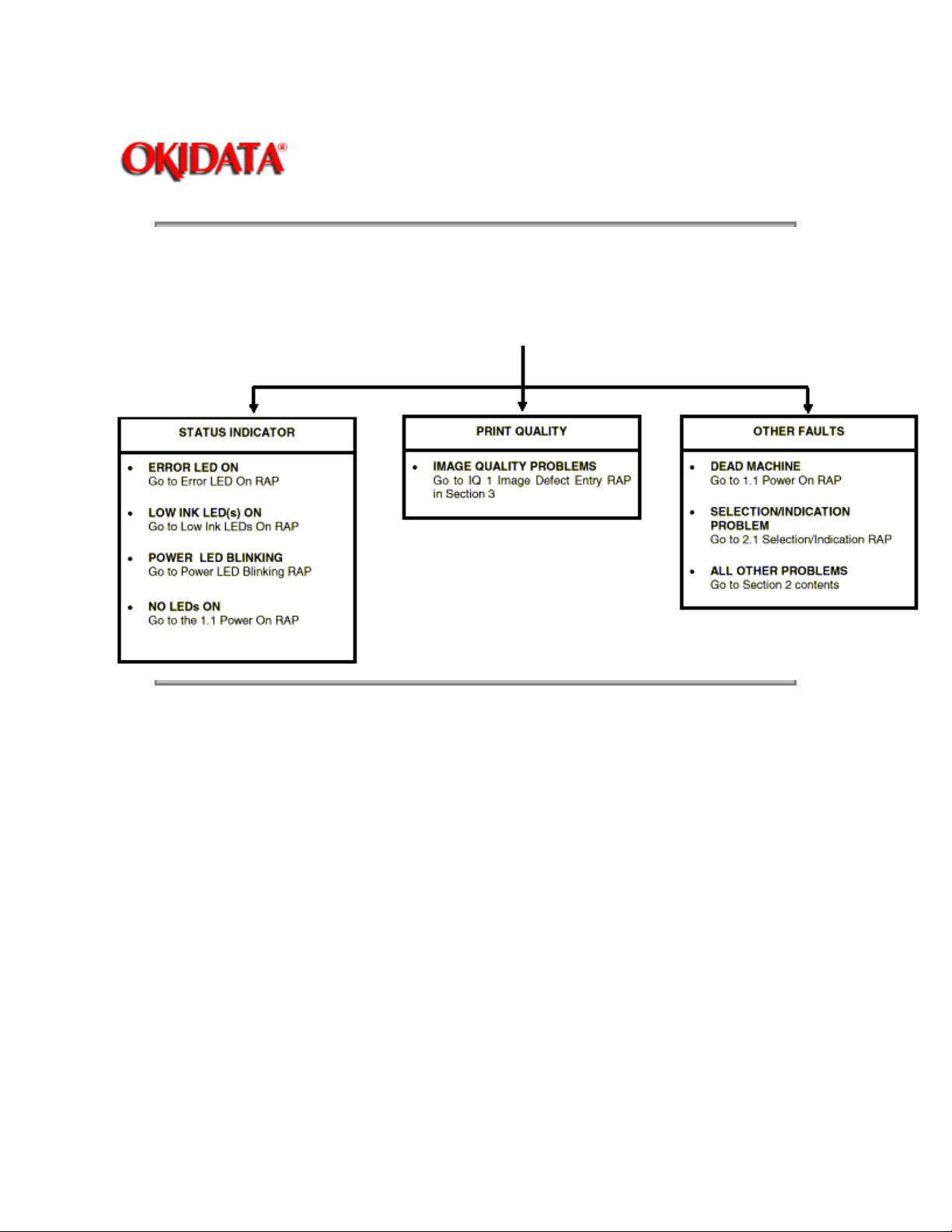
Initial Actions / System Checks
This diagram identifies how to collect the data necessary to decide how to proceed with the service call. It
classifies the problem and refers you to the appropriate Repair Analysis Procedure.
System Checkout
The System Checkout procedure is used to verify that the printer is operating properly after a repair has
been made.
Final Action
The Final Action procedure identifies the steps that must be performed before finishing the repair.
Copyright 1997, Okidata, Division of OKI America, Inc. All rights reserved. See the OKIDATA Business Partner Exchange (BPX) for
any updates to this material. (http://bpx.okidata.com)

Page: 5
Service Manual - OKIJET 2020
Chapter 0 Introduction
Section 2 - REPAIR ANALYSIS PROCEDURES (RAPs)
This section contains the Repair Analysis Procedures (RAPs) necessary to repair faults. When using a
RAP, always exit the procedure when the fault is fixed. Do not perform the remaining steps.
Copyright 1997, Okidata, Division of OKI America, Inc. All rights reserved. See the OKIDATA Business Partner Exchange (BPX) for
any updates to this material. (http://bpx.okidata.com)

Page: 6
Service Manual - OKIJET 2020
Chapter 0 Introduction
Section 3 - IMAGE QUALITY REPAIR ANALYSIS PROCEDURES (RAPs)
This section contains the Repair Analysis Procedures (RAPs) necessary to repair print quality faults. The
first RAP, IQ 1 Image Defect Entry RAP, is used to classify a print quality problem and will reference the
RAP to be used to repair the problem. When using a RAP, exit the procedure when the fault is fixed. Do
not perform the remaining steps.
Copyright 1997, Okidata, Division of OKI America, Inc. All rights reserved. See the OKIDATA Business Partner Exchange (BPX) for
any updates to this material. (http://bpx.okidata.com)

Page: 7
Service Manual - OKIJET 2020
Chapter 0 Introduction
Section 4 - REPAIR / ADJUSTMENT PROCEDURES
This section contains the repair and adjustment procedures for the printer.
Copyright 1997, Okidata, Division of OKI America, Inc. All rights reserved. See the OKIDATA Business Partner Exchange (BPX) for
any updates to this material. (http://bpx.okidata.com)

Page: 8
Service Manual - OKIJET 2020
Chapter 0 Introduction
Section 5 - PARTS LIST
This section contains the detailed Parts List for the printer.
Copyright 1997, Okidata, Division of OKI America, Inc. All rights reserved. See the OKIDATA Business Partner Exchange (BPX) for
any updates to this material. (http://bpx.okidata.com)

Page: 9
Service Manual - OKIJET 2020
Chapter 0 Introduction
Section 6 - GENERAL PROCEDURES
This section contains Diagnostic Procedures and Product Specifications for the Printer. An Overview and
Technical Overview section are also included.
Copyright 1997, Okidata, Division of OKI America, Inc. All rights reserved. See the OKIDATA Business Partner Exchange (BPX) for
any updates to this material. (http://bpx.okidata.com)

Page: 10
Service Manual - OKIJET 2020
Chapter 0 Introduction
Section 7 - WIRING DATA
This section contains Plug/ Jack Location Drawings and Block Schematic Diagrams (BSDs).
Copyright 1997, Okidata, Division of OKI America, Inc. All rights reserved. See the OKIDATA Business Partner Exchange (BPX) for
any updates to this material. (http://bpx.okidata.com)

Page: 11
Service Manual - OKIJET 2020
Chapter 0 Introduction
How To Use This Manual
The Service Call Procedures will direct you to the proper section of the Service Manual.
You should begin the service call with the Initial Actions / System Checks Procedure. From there, you will
be referenced to either Section 2, Status Indicator RAPs or Section 3, Image Quality RAPs.
If you are sent to Section 3, you will perform the IQ 1 Image Defect Entry RAP to classify the print quality
problem. You will then be directed to the proper RAP to begin your troubleshooting. From these RAPs
you may be referenced to other sections of the manual to make checks, adjustments or to replace parts.
When you have made a repair, return to the System Checkout / Final Action to complete the call.
Copyright 1997, Okidata, Division of OKI America, Inc. All rights reserved. See the OKIDATA Business Partner Exchange (BPX) for
any updates to this material. (http://bpx.okidata.com)

Page: 12
Service Manual - OKIJET 2020
Chapter 0 Introduction
Reference Symbology
Notes, adjustments, and parts lists support the checklists and the RAP information. The symbols that
refer to this supportive data are shown below.
Note
This symbol is used to refer to notes found on the same page.
Adjustments
ADJ 4.1 This symbol refers to an adjustment procedure located in Section 4 of
this Service Manual. The number adjacent to the symbol indicates the number
that is assigned to that adjustment.
Parts List
PL 10.6
Copyright 1997, Okidata, Division of OKI America, Inc. All rights reserved. See the OKIDATA Business Partner Exchange (BPX) for
any updates to this material. (http://bpx.okidata.com)
Refers to the parts list located in Section 5 of this Service Manual. The number
after the PL designation indicates the number that is assigned to that part.
Page: 13
Service Manual - OKIJET 2020
Chapter 0 Introduction
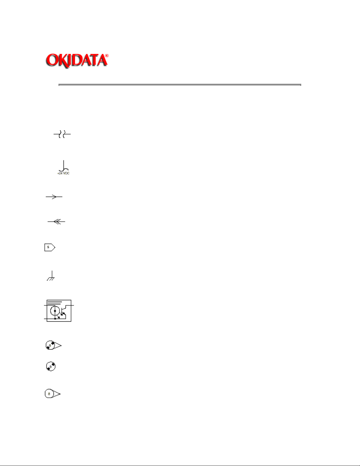
Special Symbols
Descriptions of all commonly used graphic symbols are included in order to aid in troubleshooting when
using the RAPs.
Interrupt Horizontal Signal
This indicates the continuation of a signal line which is interrupted in a horizontal
direction.
Standby Power Input
This indicates the continuation of a standby power line which is interrupted in the vertical
direction.
Left to Right Flow
This indicates the direction of signal flow.
Feedback
This indicates a feedback signal.
Flag
This is used to identify an area of a Circuit Diagram that you should check.
Ground
This indicates a machine ground.
LED / Phototransistor Sensor
This type of sensor is used in the paper path. It uses reflected light to switch the sensor
off and on.
Without Tag Change
This signal indicates that the area the triangle points to has not been modified by the tag
number in the circle.
This symbol indicates that the entire page has not been modified by the tag number in
the circle.
With Tag Change
This symbol indicates that the area the triangle points to has been modified by the tag
number in the circle.
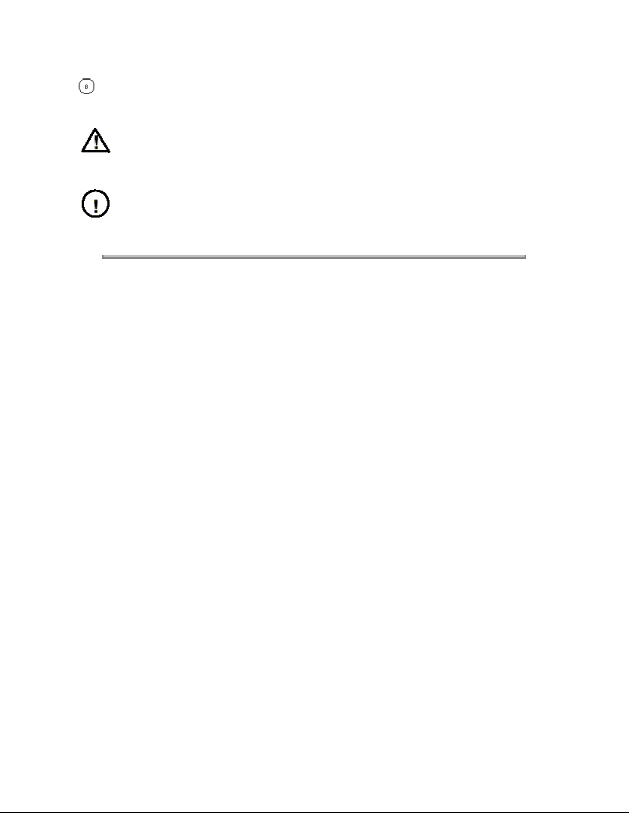
This symbol indicates that the entire page has been modified by the tag number in the
circle.
WARNING
A warning is used to alert the personnel to an operating or maintenance
procedure, practice, or condition that, if not strictly observed, could result in injury
or loss of life.
CAUTION
A caution is used to alert the personnel to an operating or maintenance procedure,
practice or condition that, if not strictly observed, could result in damage to, or destruction
of, equipment.
Copyright 1997, Okidata, Division of OKI America, Inc. All rights reserved. See the OKIDATA Business Partner Exchange (BPX) for
any updates to this material. (http://bpx.okidata.com)
Page: 14
Service Manual - OKIJET 2020
Chapter 0 Introduction
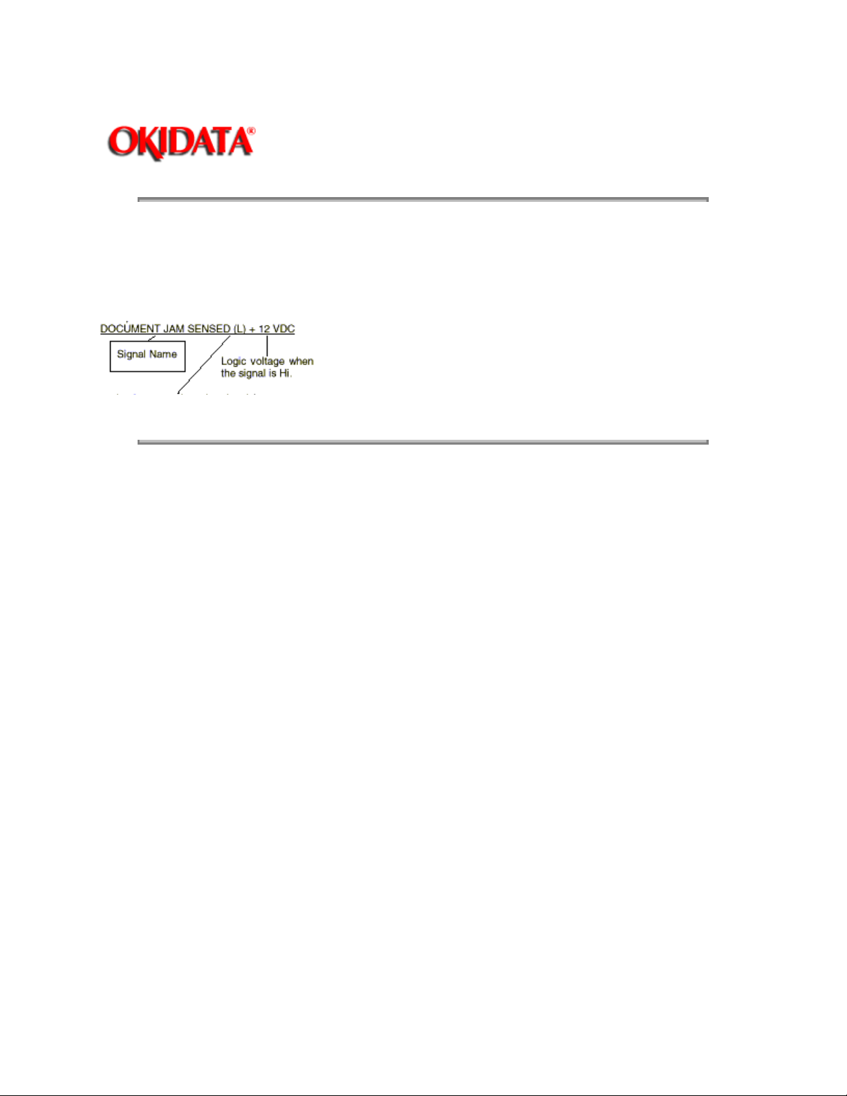
Signal Nomenclature
The signal is named to imply the condition of the machine when the signal is available.
For example:
Logic state when the signal is available in its named state. In this case, the signal is LOW when a
document jam is sensed.
Copyright 1997, Okidata, Division of OKI America, Inc. All rights reserved. See the OKIDATA Business Partner Exchange (BPX) for
any updates to this material. (http://bpx.okidata.com)
Page: 15
Service Manual - OKIJET 2020
Chapter 0 Introduction
DC Voltage Levels
DC voltages should be measured between the test point and machine GND, unless instructed otherwise.
The table below shows the values of the voltages.
Nominal Voltage
+5 VDC H
+42 VDC H
Copyright 1997, Okidata, Division of OKI America, Inc. All rights reserved. See the OKIDATA Business Partner Exchange (BPX) for
any updates to this material. (http://bpx.okidata.com)
Logic State Actual Voltage Ranges
+4.8 to +5.2 VDC
L
L
0.0 to +1.0 VDC
+39.0 to +44.0 VDC
0.0 to +3.0 VDC
Page: 16
Service Manual - OKIJET 2020
Chapter 0 Introduction
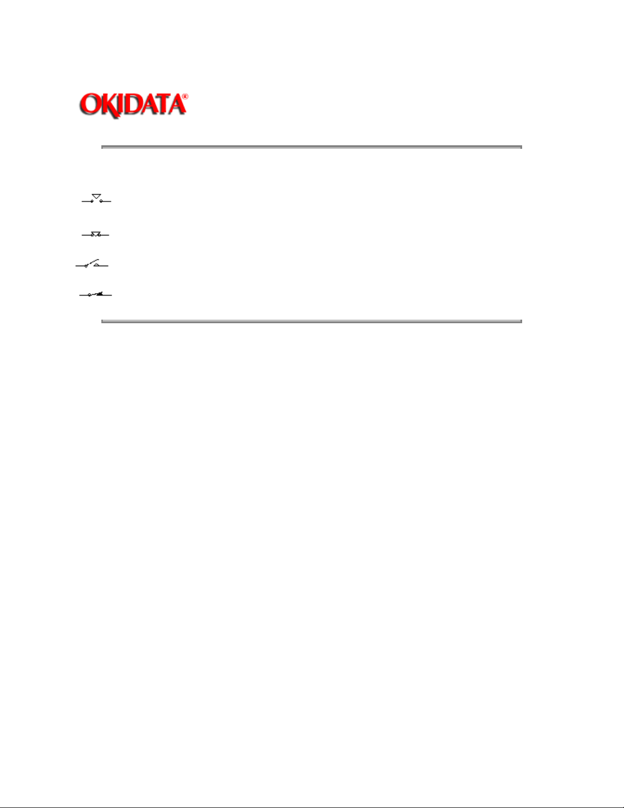
Switches and Relay Contacts
Safety interlock switch that is open.
Safety interlock switch that is closed.
Switch or relay contacts with momentary contacts shown normally open.
Switch or relay contacts with momentary contacts shown normally closed.
Copyright 1997, Okidata, Division of OKI America, Inc. All rights reserved. See the OKIDATA Business Partner Exchange (BPX) for
any updates to this material. (http://bpx.okidata.com)

Page: 17
Service Manual - OKIJET 2020
Chapter 1 Service Call Procedures
Introduction
Use the Service Call Procedures as a maintenance guide when performing any service on the printer.
Printer Maintenance - This section contains a list of the printer subsystem components to be cleaned
and /or lubricated and the cleaning and lubricating materials to be used, when that subsystem is
accessed during a repair.
Initial Actions / System Checks - This diagram identifies and classifies the printer problem and refers
you to the appropriate RAP in order to repair the problem. When the problem has been repaired,
perform the System Checkout / Final Action.
System Checkout / Final Action - This procedure should be completed at the end of every repair call
to ensure that the printer is operating properly.
Copyright 1997, Okidata, Division of OKI America, Inc. All rights reserved. See the OKIDATA Business Partner Exchange (BPX) for
any updates to this material. (http://bpx.okidata.com)

Service Manual - OKIJET 2020
Chapter 1 Service Call Procedures
Printer Maintenance
Introduction
When the printer is being serviced, the following maintenance procedure should be performed.
Procedure
Clean the following parts every time the printer is serviced:
Page: 18
Description
Cover Clean using a Lint Free Tissue and water.
Paper Feed Roller Clean using a Lint Free Tissue and water.
Paper Feed Pinch rollers and Paper Feed Guide Clean using a Lint Free Tissue and water.
Maintenance Station Clean using a Lint Free Tissue and water.
Copyright 1997, Okidata, Division of OKI America, Inc. All rights reserved. See the OKIDATA Business Partner Exchange (BPX) for
any updates to this material. (http://bpx.okidata.com)
Procedure
Service Manual - OKIJET 2020
Chapter 1 Service Call Procedures
Initial Actions
1. QUESTION THE OPERATOR.
2. VERIFY, CLASSIFY AND REPAIR THE PROBLEM.
Page: 19
Copyright 1997, Okidata, Division of OKI America, Inc. All rights reserved. See the OKIDATA Business Partner Exchange (BPX) for
any updates to this material. (http://bpx.okidata.com)

Service Manual - OKIJET 2020
Chapter 1 Service Call Procedures
System Checkout / Final Action
Reset the Ink Level Sensing count to zero. Perform the following:
Install a Color Printhead with empty ink cartridges.
Run a Test Print.
Remove the Printhead and install a Color Printhead with full ink cartridges.
Run a Test Print.
The NVM counts are now set to zero.
Print a file.
The Printer prints the selected file.
YN
Refer to Initial Action / System Checks to begin your repair.
Evaluate the print.
Is the image quality acceptable?
YN
Go to the image quality RAP identified by the IQ 1 Image Defect Entry RAP (Section 3).
Page: 20
Print and check the "Printing Alignment Test pattern".
The alignment is good.
YN
Go to the Printhead Alignment Procedure (Section Four).
Clean exterior of machine. Use a lint free tissue and water. Provide a sample of the Test Print.
Copyright 1997, Okidata, Division of OKI America, Inc. All rights reserved. See the OKIDATA Business Partner Exchange (BPX) for
any updates to this material. (http://bpx.okidata.com)

Service Manual - OKIJET 2020
Chapter 2 Repair Analysis Procedures (RAPs)
Error LED On RAP
Initial Action:
Ensure a color printhead is installed.
Remove the power cord from the printer for 10 seconds, then reinstall it.
Press the Power switch.
The Error LED is on steady.
YN
The Error LED is flashing.
YN
Press and hold the
The Error LED is steady.
YN
The Error LED is flashing.
YN
Resume/FF
Check the interface cable and connectors for an open wire or bad
connection. If OK, replace the Main Control Board.
button for 2 seconds to print the demo print.
Page: 21
Go to Error LED Flashing RAP.
Remove the power cord from the printer for 10 seconds, then reinstall it.
Press and hold the Power switch for about 2 seconds.
The carriage was noisy.
YN
The printhead stopped at each ink cartridge during the power-on cycle.
YN
Go to 6.2 Encoder RAP.
ABCD
Go to 8.1 Paper Feed RAP.
Go to 6.1 Carriage RAP.
Go to Error LED Flashing RAP.
One or more low ink LED(s) are blinking.
YN
Go to 6.1 Carriage RAP.
Go to Low Ink LED(s) on RAP.
Copyright 1997, Okidata, Division of OKI America, Inc. All rights reserved. See the OKIDATA Business Partner Exchange (BPX) for
any updates to this material. (http://bpx.okidata.com)

Page: 22
Service Manual - OKIJET 2020
Chapter 2 Repair Analysis Procedures (RAPs)
Power LED Blinking RAP
Remove the power cord from the printer for 10 seconds, the reinstall it.
The Power LED blinks.
YN
Printer is OK.
Go to 2.1 Selection/Indication RAP.
Copyright 1997, Okidata, Division of OKI America, Inc. All rights reserved. See the OKIDATA Business Partner Exchange (BPX) for
any updates to this material. (http://bpx.okidata.com)
Service Manual - OKIJET 2020
Chapter 2 Repair Analysis Procedures (RAPs)
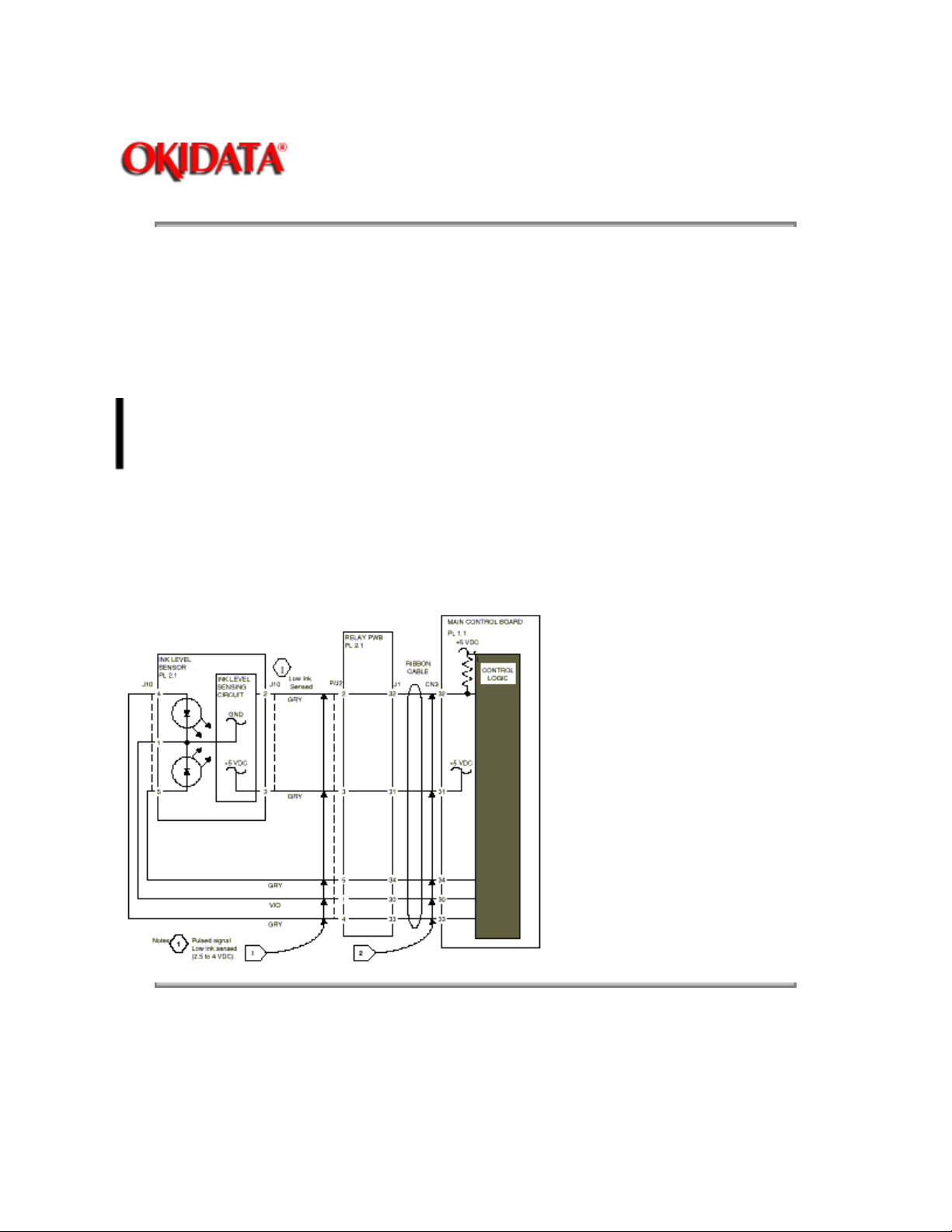
Low Ink LED(s) On RAP
Initial Action:
Ensure all the ink cartridges are full and properly seated.
Page: 23
Go to Flags 1 and 2. Check the wires and connections for an open circuit.
YN
Repair the wires or connections if possible.
Replace the main control board.
If the problem still exists, replace the Printer.
Replace the Ink Level Sensor (PL 2.1).
Replace the main control board.
If the problem still exists, replace the printer.
The wires are good.
Copyright 1997, Okidata, Division of OKI America, Inc. All rights reserved. See the OKIDATA Business Partner Exchange (BPX) for
any updates to this material. (http://bpx.okidata.com)

Page: 24
Service Manual - OKIJET 2020
Chapter 2 Repair Analysis Procedures (RAPs)
Error LED Flashing RAP
Note:
This procedure will work only when the Error LED is flashing.
Note:
In the following procedure, the Error LED and Power LED will be used to display an 8 bit binary
error code. The LEDs will flash in 1/2 second intervals. The code will be displayed 4 bits at a time. The
LED code is as follows (See Figure 1):
1 = Both Error and Power LEDs lit
0 = Error LED only is lit
Press and release the Resume/ FF button, while observing the Error and Power LEDs.1.
4 bits will be flashed in 1/ 2 second intervals followed by a pause, then 4 more bits in 1/ 2 second 2.
intervals. After the cycle, the Error LED will continue to flash.
Determine the code and go to the Error Code Chart (Table 1) for the corrective action.3.
Repeat step 1 as many times as necessary to determine the code.4.
Error Code Error Description Corrective Action
1000 1000 ROM error Replace the Main Control Board
1000 1100 RAM error Replace the Main Control Board
1100 1000 EPROM error Replace the Main Control Board
1110 1000 CPU error Replace the Main Control Board
1100 1111 Carriage home position error Go to 6.1 Carriage RAP
Copyright 1997, Okidata, Division of OKI America, Inc. All rights reserved. See the OKIDATA Business Partner Exchange (BPX) for
any updates to this material. (http://bpx.okidata.com)

Service Manual - OKIJET 2020
Chapter 2 Repair Analysis Procedures (RAPs)
1.1 Power on RAP
Refer to Figure 1.
YN
Disconnect the power cord.
Check fuse F1 on the Power
Supply.
F1 is blown.
YN
Replace the blown fuse.
If the problem is not corrected, replace the Power Supply (PL 1.1).
Refer to Figure 1. There is +5 VDC measured on the Main Control Board.
YN
Go to Flag 2 and check for a short to ground. If OK, replace the Power Supply. If problem still
exists, replace Main Control Board.
There is +42 VDC measured on the Main Control Board.
Go to Flag 1 (Figure 2) and check the wires for an open circuit. If good, replace the Power
Supply. If problem still exists, replace the Main Control Board.
Page: 25
Replace the Main Control Board before replacing the Control Panel Assembly.

Copyright 1997, Okidata, Division of OKI America, Inc. All rights reserved. See the OKIDATA Business Partner Exchange (BPX) for
any updates to this material. (http://bpx.okidata.com)

Service Manual - OKIJET 2020
Chapter 2 Repair Analysis Procedures (RAPs)
2.1 Selection/Indication RAP
Load paper.
Disconnect and then reconnect the power cord while observing the LEDs.
All LEDs light momentarily when the power cord is reconnected.
YN
One or more LEDs light.
YN
Go to 1.1 Power on RAP.
Go to Flag 1 and Flag 2 and check for an open wire. If OK, replace the Control Panel
Assembly.
All LEDs go out in approximately 10 seconds.
YN
If the Power LED remains on (flashing), go to Flag 3 and check for an open wire. If OK,
replace the Control Panel Assembly.
Page: 26
Press and hold the Power button for approximately 2 seconds to turn on the printer.
Press and hold the
Paper feeds.
YN
Go to Flag 5 and check for an open wire.
If good, go to 8.1 Paper Feed RAP.
A
A
Press the Cartridge Change button.
The carriage moves to the center position.
YN
Go to Flag 4 and check for an open wire.
If OK, replace the Control Panel Assembly.
For printer set up problems when printing from a DOS application, consult GP 2 Printing with
DOS Procedure in Section 6.
Examples of printer set up problems.
Resume/FF
button for 2 seconds.
When trying to print from the host, the paper continues to linefeed without outputting any print.

Just a few lines of data are printed and then the paper continues to line feed without printing.
Copyright 1997, Okidata, Division of OKI America, Inc. All rights reserved. See the OKIDATA Business Partner Exchange (BPX) for
any updates to this material. (http://bpx.okidata.com)

6.1 Carriage TAP
Disconnect and then reconnect the power cord.
Press and hold the Power switch.
The carriage moves.
YN
Go to Flag 1 and check the ribbon cable for being open or damaged.
Go to Flag 2 and check for an open circuit. If the wire is good, replace the Main
Control Board.
Check / replace the ribbon carriage cable.
Check the teeth on the belt.
Check the teeth on the carriage motor.
Check for 42 volts.
If 42 volts aren't being supplied by the power supply, replace the power supply.
Check / replace the carriage motor.
Perform the following:
Check that the Printhead ribbon cable going to CN4 on the Main Control Board is
connected properly.
Go to Flag 2 and Flag 3 and check for an open circuit.
If the wires are good, replace the Printhead Ribbon Cable (PL 2.1).
If the problem continues replace the Main Control Board (PL 1.1).
Check / replace the ribbon carriage cable.
Check the teeth on the belt.
Check the teeth on the carriage motor.
Check for 42 volts.
If 42 volts aren't being supplied by the power supply, replace the power
supply.
Check / replace the carriage motor.
Page: 27
Service Manual - OKIJET 2020
Chapter 2 Repair Analysis Procedures (RAPs)
Copyright 1997, Okidata, Division of OKI America, Inc. All rights reserved. See the OKIDATA Business Partner Exchange (BPX) for
any updates to this material. (http://bpx.okidata.com)

6.2 Encoder RAP
Go to Flag 1 and check the ribbon
Go to Flag 4 and check for an open circuit.
Replace the Encoder.
Go to 6.1 Carriage RAP.
Page: 28
Service Manual - OKIJET 2020
Chapter 2 Repair Analysis Procedures (RAPs)
Copyright 1997, Okidata, Division of OKI America, Inc. All rights reserved. See the OKIDATA Business Partner Exchange (BPX) for
any updates to this material. (http://bpx.okidata.com)

Service Manual - OKIJET 2020
Chapter 2 Repair Analysis Procedures (RAPs)
8.1 Paper Feed RAP
Clear any paper in the printer.
Disconnect and then reconnect the power cord.
Press and hold the Power switch for about 2 seconds.
Press and hold the
The paper feeds or partially feeds.
YN
Go to Flag 2 and check the paper feed switch circuit for an open.
If OK, go to Flag 3 and check for an open circuit.
Replace the Back pad.
If the problem still exists, replace the Main Control Board.
Resume/FF
Check that the Paper Tray is installed correctly (REP 1.1)
Go to Flag 1 and check the cam sensor circuit for an open.
If OK, go to Flag 3 and check for an open circuit. If paper feed motor circuit is
button for 2 seconds to print the demo print.
defective, replace the paper feed motor.
If the wires are good, replace the Main Control Board.
Page: 29
Copyright 1997, Okidata, Division of OKI America, Inc. All rights reserved. See the OKIDATA Business Partner Exchange (BPX) for

any updates to this material. (http://bpx.okidata.com)

Service Manual - OKIJET 2020
Chapter 2 Repair Analysis Procedures (RAPs)
9.1 Blank Print RAP
Initial Action:
Ensure that the Printhead latch is positioned towards the rear.
Unlatch the Printhead, reset the Printhead and latch it back into position. If problem still exists:
Replace the Printhead.
Go to Flag 1 and check the ribbon cable for being damaged.
Check the terminals of J11 on the Carriage Assembly and J12 on the Ink Cartridge for being
contaminated or damaged. Clean or repair as necessary.
If the problem still exists, replace the Printhead Ribbon Cable (PL 2.1).
Page: 30
Copyright 1997, Okidata, Division of OKI America, Inc. All rights reserved. See the OKIDATA Business Partner Exchange (BPX) for
any updates to this material. (http://bpx.okidata.com)

IQ 1 Image Defect Entry RAP
1. Print the Test Print:
a. Load paper into the Paper Tray.
Page: 31
Service Manual - OKIJET 2020
Chapter 3 Image Quality RAPs
b. Press and hold the
the Printer power off.
c. While pressing and holding the
The printer prints the test print shown in Figure 1. When the test print is complete, the printer initializes
and returns to the Ready status.
d. If the test print fails to print, repeat steps a through c.
2. Refer to the DEFECT Column in Table 1 that best describes the image quality problem.
3. If the problem is with external input only, replace the Main Control Board.
Power on / Reset
Resume/ FF
button for approximately 2 seconds and then release, to switch
button press and release the
Power on / Reset
button.
Copyright 1997, Okidata, Division of OKI America, Inc. All rights reserved. See the OKIDATA Business Partner Exchange (BPX) for
any updates to this material. (http://bpx.okidata.com)

IQ 1 Image Defect Entry RAP Table
Page: 32
Service Manual - OKIJET 2020
Chapter 3 Image Quality RAPs
DEFECT
Blank print Printhead
White horizontal lines and
Streaks
CAUSE SOLUTION
The Printhead
nozzles may be
blocked.
Print is faint or missing A non
recommended
paper is being used
or the paper is
damp.
Defective Cartridge.
The ink supply may
be nearly empty.
The Printhead
nozzles may be
blocked.
Blurry or jagged vertical
lines
Print image is clipped or
off edge of media
Printhead
Alignment
Paper
Print off edge of
media.
Document margins
may exceed printer
margins.
Remove and reinstall the Printhead.1.
Press the
2.
Cartridge Change / Clean
button for 2 seconds to clean and restore
the Printhead. Repeat if necessary.
If the problem still exists go to the 9.1 Blank
Print RAP.
Perform the following:
Press the
1.
Cartridge Change / Clean
button for 2 seconds to clean and restore
the Printhead.
Make another Test Print. If the print still 2.
has lines and streaks repeat the above
process up to 5 times.
If the problem still exists, replace the 3.
Printhead.
Replace the paper.
Perform the following:
Press and hold the
1.
Clean
button for 2 seconds to clean and
Cartridge Change /
restore the Printhead.
Run a Test Print. If the print is still faint, 2.
repeat the process up to 2 more times.
If the problem is still not corrected 3.
replace the Printhead.
Perform ADJ 2.0 Printhead Alignment
Procedure
If the problem still exists switch the printer to
the High Quality print mode (in the printer
driver..)
Turn the paper over to print on the opposite
side.
Ensure that the Print Driver setup has the
correct selection of media size and type.
Adjust margins in the application as
necessary.
Copyright 1997, Okidata, Division of OKI America, Inc. All rights reserved. See the OKIDATA Business Partner Exchange (BPX) for

any updates to this material. (http://bpx.okidata.com)

Service Manual - OKIJET 2020
Chapter 4 Repair / Adjustment Procedures
REP 1.0 Printhead
Parts List on PL 2. 2
Removal
1. Open the Cartridge Cover (PL 1.1).
2. Center the carriage using either of the following procedures:
Press the Cartridge Change / Clean button.
WARNING: Switch off the power. Disconnect the power cord from the wall outlet.
Grasp and manually move the belt (PL 2.1) in order to center the Printhead (Figure 1).
Page: 33
CAUTION:
time will cause the ink nozzles to dry out. Image quality defects or a blank page could result. If
necessary, prime the printhead after reinstallation. (See below to Refer to the Replacement / Priming
section of this procedure.)
3. Move the Printhead lock lever toward the front of the printer.
4. Lift and remove the Printhead. Store it in the Storage Box.
Replacement / Priming
1. Install the Printhead onto the Printhead vertical guide.
2. Move the Printhead lock lever toward the rear of the printer.
3. Close the Cartridge Cover.
4. Press the Resume / FF button to prime the Printhead.
NOTE:
of the standard printhead.
Store the Printhead in the Storage Box. Leaving the Printhead removed for long periods of
The optional high capacity printhead is shown. Refer to the User's Documentation for illustrations

Copyright 1997, Okidata, Division of OKI America, Inc. All rights reserved. See the OKIDATA Business Partner Exchange (BPX) for
any updates to this material. (http://bpx.okidata.com)

Page: 34
Service Manual - OKIJET 2020
Chapter 4 Repair / Adjustment Procedures
REP 1.1 Paper Tray Assembly
Parts List on PL 1. 1
Removal
1. Remove the Output Tray (PL 1.1).
2. Press the two handles toward the rear of the printer to release the latches (Figure 1).
3. Pivot the Paper Tray Assembly toward the back of the printer to disengage the three tabs at the bottom
of the Paper Tray Assembly from the tabs on the Paper Feed / Carriage Assembly.
4. Lift the Paper Tray Assembly from the printer.
Replacement
1. Retract the moveable face of the Paper Tray Assembly by pressing it toward the back of the Paper
Tray Assembly.
2. Insert the Paper Tray Assembly into the printer (with bottom of tray touching the bottom of the tray
opening on the printer) ensuring the moveable face is behind the white cam (near the bottom, on the left).
See Figure 2.
3. Engage the three tabs at the bottom of the Paper Tray Assembly with the tabs on the Paper Feed /
Carriage Assembly.
4. Rotate the Paper Tray Assembly toward the front of the printer.
5. Engage the two latches by gently pulling the handles downward and toward the front of the printer until
the latches snap into position.

6. Reinstall the Output Tray.
Copyright 1997, Okidata, Division of OKI America, Inc. All rights reserved. See the OKIDATA Business Partner Exchange (BPX) for
any updates to this material. (http://bpx.okidata.com)

Page: 35
Service Manual - OKIJET 2020
Chapter 4 Repair / Adjustment Procedures
REP 1.2 Cartridge Cover
Parts List on PL 1. 1
Removal
1. Open the Cartridge Cover (PL 1.1).
2. Utilizing a screwdriver or similar tool, slightly separate the Cartridge Cover and Top Cover at either
pivot to release the Cartridge Cover pivot from the Top Cover (Figure 1).
3. Lift the Cartridge Cover from the printer.
Replacement
1. Insert either Cartridge Cover pivot into the corresponding Top Cover pivot hole.
2. Utilizing a screwdriver or similar tool, slightly separate the Cartridge Cover and Top Cover at the
opposite pivot.
3. Position the Cartridge Cover pivot to engage with the pivot hole of the Top Cover.
4. Close the Cartridge Cover.
Copyright 1997, Okidata, Division of OKI America, Inc. All rights reserved. See the OKIDATA Business Partner Exchange (BPX) for
any updates to this material. (http://bpx.okidata.com)

REP 1.3 Top Cover
Parts List on PL 1. 1
Removal
Page: 36
Service Manual - OKIJET 2020
Chapter 4 Repair / Adjustment Procedures
CAUTION:
will cause the ink nozzles to dry out. Image quality defects or a blank page could result. If necessary,
prime the printhead after
reinstallation. (REP 1.0)
1. Remove the Printhead (REP 1.0). Store the Printhead in the Storage Box.
WARNING: Switch off the power. Disconnect the power cord from the wall outlet.
2. Remove the Output Tray (PL 1.1).
3. Remove the Paper Tray Assembly (REP 1.1).
4. Remove the Cartridge Cover (REP 1.2).
5. Lay the printer on it's back; release the three front latch tabs (Figure 1).
CAUTION:
is connected to the Control Panel Assembly, which is located inside the Top Cover.
NOTE:
6. Return the printer to its normal operating position. Lift and hold the front of the cover slightly while
releasing the two rear latch tabs. Then lift the rear of the cover and pivot towards the FRONT of the
printer to remove.
Store the Printhead in the Storage Box. Leaving the cartridge removed for long periods of time
While removing the Top Cover from the printer, take care not to damage the ribbon cable that
The rear of the Top Cover has three locator tabs and two latch tabs.
Replacement
1. Ensure the ribbon cable is properly routed and not twisted during Top Cover installation.
2. If previously disconnected, reconnect ribbon cable to the Control Panel Assembly.
3. Position the Top Cover on the printer. Align and latch the rear latches; then the front latches.
4. Reinstall the following:
a. Cartridge Cover (REP 1.2)
b. Paper Tray Assembly (REP 1.1)
c. Output Tray (PL 1.1)

d. Printhead (REP 1.0)
Copyright 1997, Okidata, Division of OKI America, Inc. All rights reserved. See the OKIDATA Business Partner Exchange (BPX) for
any updates to this material. (http://bpx.okidata.com)

REP 1.4 Exit Guide
Parts List on PL 2. 2
Removal
Page: 37
Service Manual - OKIJET 2020
Chapter 4 Repair / Adjustment Procedures
CAUTION:
time will cause the ink nozzles to dry out. Image quality defects or a blank page could result. If necessary,
prime the printhead after reinstallation. (REP 1.0)
1. Remove the Printhead (REP 1.0). Store the Printhead in the Storage Box.
WARNING:
2. Remove the Output Tray (PL 1.1).
3. Remove the Cartridge Cover (REP 1.2).
4. Position both thumbs at the lower, front corners of the Exit Guide (Figure 1). Apply modest pressure
simultaneously toward the rear and up to unlatch the Exit Guide.
5. Rotate the guide approximately 90° up and toward the rear of the printer.
6. Lift the Exit Guide from the printer.
Replacement
1. Hold the Exit Guide so the star wheels (10) are facing the front of the printer.
2. Lower the Exit Guide into the printer to engage the pivots with the slots in the Paper Feed / Carriage
Assembly.
Store the Printhead in the Storage Box. Leaving the Printhead removed for long periods of
Switch off the power. Disconnect the power cord from the wall outlet.
3. Rotate the Exit Guide completely toward the front of the printer.
4. Position both thumbs at the lower, front corners of the Exit Guide (Figure 1). Apply moderate pressure
simultaneously toward the rear and down to latch the Exit Guide.
5. Reinstall the Cartridge Cover (REP 1.2).
6. Reinstall the Output Tray (PL 1.1).
7. Reinstall the Printhead (REP 1.0).

Copyright 1997, Okidata, Division of OKI America, Inc. All rights reserved. See the OKIDATA Business Partner Exchange (BPX) for
any updates to this material. (http://bpx.okidata.com)

REP 1.5 Paper Feed / Carriage Assy.
Parts List on PL 2. 1
Removal
Page: 38
Service Manual - OKIJET 2020
Chapter 4 Repair / Adjustment Procedures
CAUTION:
time will cause the ink nozzles to dry out. Image quality defects or a blank page could result. If necessary,
prime the printhead after reinstallation. (REP 1.0)
1. Remove the Printhead (REP 1.0). Store the Printhead in the Storage Box.
WARNING:
2. Remove the Output Tray (PL 1.1).
3. Remove the Paper Tray Assembly (REP 1.1).
4. Remove the Cartridge Cover (REP 1.2).
5. Remove the Top Cover (REP 1.3).
6. Loosen screw; disconnect ground wire from ground plate near front, left corner of Paper Feed /
Carriage Assembly (Figure 1).
Store the Printhead in the Storage Box. Leaving the Printhead removed for long periods of
Switch off the power. Disconnect the power cord at the wall outlet.
7. Disconnect ground wire from grounding plate at right side of printer (Figure 2).

8. Remove the screws (2) from the two front corners of the Paper Feed / Carriage Assembly (Figure 3).
9. Lift the front of the assembly slightly, then slide the assembly toward the front of the printer until it
contacts the front wall of the base.
10. Lift the front of the assembly to access the Main Control Board ribbon cable connectors, CN3 & CN4;
disconnect from the Main Control Board (Figure 4).
11. Remove the assembly from the base.
Replacement

1. Lift the front of the assembly to access the Main Control Board ribbon cable connectors, CN3 & CN4;
reconnect to the Main Control Board (Figure 4 - see above).
2. Allow the Paper Feed / Carriage Assembly to rest on the printer base. Slide the assembly rearward to
engage the rear mounts.
3. Reinstall the two front screws.
4. Reconnect the ground wire to the ground plate on the right side of the printer.
5. Reconnect the ground wire to the ground plate on the left, front corner of the printer; tighten screw.
6. Reinstall the following:
a. Top Cover (REP 1.3)
b. Cartridge Cover (REP 1.2)
c. Paper Tray Assembly (REP 1.1)
d. Output Tray (PL 1.1)
e. Printhead (REP 1.0)
Copyright 1997, Okidata, Division of OKI America, Inc. All rights reserved. See the OKIDATA Business Partner Exchange (BPX) for
any updates to this material. (http://bpx.okidata.com)

REP 1.6 Power Supply
Parts List on PL 1. 1
Removal
Page: 39
Service Manual - OKIJET 2020
Chapter 4 Repair / Adjustment Procedures
CAUTION:
time will cause the ink to dry out. Image quality defects a blank page could result. If necessary, prime the
printhead after reinstallation. (REP 1.0)
1. Remove the Printhead (REP 1.0). Store the Printhead in the Storage Box.
WARNING
2. Remove the Output Tray (PL 1.1).
3. Remove the Paper Tray Assembly (REP 1.1).
4. Remove the Cartridge Cover (REP 1.2).
5. Remove the Top Cover (REP 1.3).
6. Remove the Paper Feed / Carriage Assembly (REP 1. 5).
7. Disconnect Power Supply power cord connector CN1 from the Power Supply (Figure 1).
8. Remove the four mounting screws.
9. Slide the Power Supply toward the right side of the printer to disengage Power Supply connector CN2
from the Main Control Board connector CN1; lift the Power Supply from the printer.
Store the Printhead in the Storage Box. Leaving the Printhead removed for long periods of
: Switch off the Power. Disconnect the power cord at the wall outlet.
Replacement
1. Position the Power Supply into the printer base.
2. Slide the Power Supply toward the left side of the printer to engage Power Supply connector CN2 with
the Main Control Board (Figure 1).
3. Install the four mounting screws.
4. Reconnect the Power Supply power cord connector CN1.
5. Replace the following:
a. Paper Feed / Carriage Assembly (REP 1. 5)
b. Top Cover (REP 1.3)

c. Cartridge Cover (REP 1.2)
d. Paper Tray Assembly (REP 1.1)
e. Output Tray (PL 1.1)
f. Printhead (REP 1.0)
Copyright 1997, Okidata, Division of OKI America, Inc. All rights reserved. See the OKIDATA Business Partner Exchange (BPX) for
any updates to this material. (http://bpx.okidata.com)

REP 1.7 Main Control Board
Parts List on PL 1. 1
Removal
Page: 40
Service Manual - OKIJET 2020
Chapter 4 Repair / Adjustment Procedures
CAUTION:
time will cause the ink nozzles to dry out. Image quality defects or a blank page could result. If necessary,
prime the printhead after reinstallation. (REP 1.0)
1. Remove the Printhead (REP 1.0). Store the cartridge in the Storage Box.
WARNING:
2. Remove the Output Tray (PL 1.1).
3. Remove the Paper Tray Assembly (REP 1.1).
4. Remove the Cartridge Cover (REP 1.2).
5. Remove the Top Cover (REP 1.3).
6. Remove the Paper Feed / Carriage Assembly (REP 1. 5).
7. Remove the Power Supply (REP 1.6).
8. Disconnect Main Control Board connector CN2 from the Main Control Board (Figure 1).
NOTE:
than the others. Ensure to replace them in their correct positions.
Store the Printhead in the Storage Box. Leaving the Printhead removed for long periods of
Switch off the power. Disconnect the power cord at the wall outlet.
The two screws securing the PC interface cable connector to the Main Control Board are longer
9. Remove the eight mounting screws and ground wire (Figure 1).
NOTE:
the Main Control Board.
NOTE:
Control Board removal.
10. Remove the Main Control Board.
It may be necessary to detach the ribbon cable and ferrite from the printer base before removing
Exercise care not to deform the two PC interface cable connector wire-form locks during Main

Replacement
NOTE:
There are 2 different length screws securing the Main Control Board. Be sure to reinstall the two
longer screws through the PC interface cable connector.
1. Position the Main Control Board into the printer base.
2. Reinstall the ground wire as per Figure 1.
3. Reinstall mounting screws.
4. Reconnect connector CN2 to the Main Control Board.
5. If previously detached, reattach the ribbon cable and ferrite to the printer base.
6. Replace the following:
a. Power Supply (REP 1.6)
b. Paper Feed / Carriage Assembly (REP 1. 5)
c. Top Cover (REP 1.3)
d. Cartridge Cover (REP 1.2)
e. Paper Tray Assembly (REP 1.1)
f. Output Tray (PL 1.1)
g. Printhead (REP 1.0)
Copyright 1997, Okidata, Division of OKI America, Inc. All rights reserved. See the OKIDATA Business Partner Exchange (BPX) for
any updates to this material. (http://bpx.okidata.com)

REP 1.8 Waste Ink Pad
Parts List on PL 1. 1
Replacement
Page: 41
Service Manual - OKIJET 2020
Chapter 4 Repair / Adjustment Procedures
NOTE:
longer screws through the PC interface cable connector.
1. Position the Main Control Board into the printer base.
2. Reinstall the ground wire as per Figure 1.
3. Reinstall mounting screws.
4. Reconnect connector CN2 to the Main Control Board.
5. If previously detached, reattach the ribbon cable and ferrite to the printer base.
6. Replace the following:
a. Power Supply (REP 1.6)
b. Paper Feed / Carriage Assembly (REP 1. 5)
c. Top Cover (REP 1.3)
d. Cartridge Cover (REP 1.2)
e. Paper Tray Assembly (REP 1.1)
There are 2 different length screws securing the Main Control Board. Be sure to reinstall the two
f. Output Tray (PL 1.1)
g. Printhead (REP 1.0)
Removal
CAUTION:
time will cause the ink nozzles to dry out. Image quality defects or a blank page could result. If necessary,
prime the printhead after reinstallation. (REP 1.0)
1. Remove the Printhead (REP 1.0). Store the Printhead in the Storage Box.
WARNING:
2. Remove the following:
Store the Printhead in the Storage Box. Leaving the Printhead removed for long periods of
Switch off the power. Disconnect the power cord at the wall outlet.

a. Output Tray (PL 1.1)
b. Paper Tray Assembly (REP 1.1)
c. Cartridge Cover (REP 1.2)
d. Top Cover (REP 1.3)
e. Paper Feed / Carriage Assembly (REP 1. 5)
3. Remove Waste Ink Pad retainer by releasing the four locking tabs with screwdriver or other similar tool
(Figure. 1).
Replacement
1. Ensure flange on one end of the pad retainer is toward the right side of the printer.
2. Snap the retainer into position.
3. Replace the following:
a. Paper Feed / Carriage Assembly (REP 1. 5)
b. Top Cover (REP 1.3)
c. Cartridge Cover (REP 1.2)
d. Paper Tray Assembly (REP 1.1)
e. Output Tray (PL 1.1)
f. Printhead (REP 1.0)
Copyright 1997, Okidata, Division of OKI America, Inc. All rights reserved. See the OKIDATA Business Partner Exchange (BPX) for

any updates to this material. (http://bpx.okidata.com)

REP 1.9 Pump
Parts List on PL 2. 1
Removal
Page: 42
Service Manual - OKIJET 2020
Chapter 4 Repair / Adjustment Procedures
CAUTION:
time will cause the ink nozzles to dry out. Image quality defects or a blank page could result. If necessary,
prime the printhead after reinstallation. (REP 1.0)
1. Remove the Printhead (REP 1.0). Store the Printhead in the Storage Box.
WARNING:
2. Remove the following:
a. Output Tray (PL 1.1)
b. Paper Tray Assembly (REP 1.1)
c. Cartridge Cover (REP 1.2)
d. Top Cover (REP 1.3)
e. Paper Feed / Carriage Assembly (REP 1. 5)
3. Remove the Pump from the Paper Feed / Carriage Assembly.
a. Note routing of inlet tube; disconnect tube at connector beneath Maintenance Station (Figure 1).
b. Note routing of outlet tube; remove cable tie; slide tube through frame.
Store the Printhead in the Storage Box. Leaving the Printhead removed for long periods of
Switch off the power. Disconnect the power cord at the wall outlet.
c. Remove two Pump mounting screws. (Figure 2).
d. Slide pump from motor shaft.
Replacement
1. Install the pump onto the motor shaft.
2. Reinstall the two mounting screws.
CAUTION:
3. Route inlet tube as shown in Figure 1; reconnect; clamp into position.
4. Route outlet tube as shown in Figure 1; install two cable ties on tube at either side of frame to ensure
Ensure the pump tubing is not kinked or otherwise restricted during reinstallation.

tube exits onto Waste Ink Pad.
5. Reinstall the following:
a. Paper Feed / Carriage Assembly (REP 1. 5)
b. Top Cover (REP 1.3)
c. Cartridge Cover (REP 1.2)
d. Paper Tray Assembly (REP 1.1)
e. Output Tray (PL 1.1)
f. Printhead (REP 1.0)
Copyright 1997, Okidata, Division of OKI America, Inc. All rights reserved. See the OKIDATA Business Partner Exchange (BPX) for
any updates to this material. (http://bpx.okidata.com)

REP 1.10 Maintenance Station
Parts List on PL 2. 1
Removal
Page: 43
Service Manual - OKIJET 2020
Chapter 4 Repair / Adjustment Procedures
CAUTION:
time will cause the ink nozzles to dry out. Image quality problems or a blank page could result. If
necessary, prime the printhead after reinstallation. (REP 1.0)
1. Remove the Printhead (REP 1.0). Store the Printhead in the Storage Box.
WARNING:
2. Remove the following:
a. Output Tray (PL 1.1)
b. Paper Tray Assembly (REP 1.1)
c. Cartridge Cover (REP 1.2)
d. Top Cover (REP 1.3)
3. Observe the routing of the tube from the Maintenance Station to the connector located below the
Maintenance Station. Disconnect this tube at the tube connector.
4. Move the Printhead carriage to the extreme right side of the printer.
5. Remove the mounting screw (Figure 1).
Store the Printhead in the Storage Box. Leaving the Printhead removed for long periods of
Switch off the power. Disconnect the power cord at the wall outlet.
6. Lift and hold the left side of the paper pressure baffle approximately six millimeters away from the
Maintenance Station.
NOTE:
7. Slide the Maintenance Station toward the front of the printer to disengage the mounting tabs, then lift
upward to remove Maintenance Station from the printer.
Observe the tube routing during Maintenance Station removal.

Replacement
CAUTION:
1. Route the Maintenance Station tube as observed during removal.
2. Lift and hold the left side of the paper pressure baffle approximately six millimeters away from the
Maintenance Station.
3. Lower the Maintenance Station into position to insert the mounting tabs.
4. Slide the Maintenance Station toward the rear of the printer to engage the mounting tabs.
5. Secure with mounting screw (machine threads).
6. Connect tube to its mating connector.
7. Ensure tube is routed between the pinch arm and the Maintenance Station body (Figure 2).
8. Reinstall the following:
a. Top Cover (REP 1.3)
b. Cartridge Cover (REP 1.2)
c. Paper Tray Assembly (REP 1.1)
Ensure the Printhead carriage is positioned to the extreme right side of the printer.
d. Output Tray (PL 1.1)
e. Printhead (REP 1.0)

Copyright 1997, Okidata, Division of OKI America, Inc. All rights reserved. See the OKIDATA Business Partner Exchange (BPX) for
any updates to this material. (http://bpx.okidata.com)

REP 1.11 Encoder
Parts List on PL 2. 1
Removal
Page: 44
Service Manual - OKIJET 2020
Chapter 4 Repair / Adjustment Procedures
CAUTION:
time will cause the ink nozzles to dry out. Image quality problems or a blank page could result. If
necessary, prime the printhead after reinstallation. (REP 1.0)
1. Remove the Printhead (REP 1.0). Store the Printhead in the Storage Box.
WARNING:
2. Remove the following:
a. Paper Output shelf (PL 1.1)
b. Paper Tray Assembly (REP 1.1)
c. Cartridge Cover (REP 1.2)
d. Top Cover (REP 1.3)
e. Paper Feed / Carriage Assembly (REP 1. 5)
f. Maintenance Station (REP 1.10).
3. Remove the belt (PL 2.1) from the carriage motor pulley (right end).
4. Remove the belt from the Encoder pulley (left end).
Store the Printhead in the Storage Box. Leaving the Printhead removed for long periods of
Switch off the power. Disconnect the power cord at the wall outlet.
CAUTION:
removing the carriage assembly.
5. Rotate the carriage shaft cams so that their flats are aligned with the sides of the slot on each side
frame (Figure 1).
A ribbon cable is attached to the bottom of the carriage assembly. Do not damage it while

NOTE:
Expect moderate to heavy resistance when removing carriage end cams from printer side frames.
CAUTION:
Simultaneously slide both cams from their respective slots (Figure 2).
CAUTION:
6. Remove the carriage from printer side frames (Figure 2).
7. Position the Paper Feed / Carriage Assembly as shown in Figure 3..
8. Disconnect the Encoder connector (J4) from the Relay BOARD (Figure 3).
Ensure no portion of carriage is beneath ink level sensor during carriage removal.
Take care not to damage ribbon cable while removing the carriage.
NOTE:
9. Release the Encoder harness from the carriage tabs.
Observe Encoder harness routing before removing Encoder.

10. Return the Paper Feed / Carriage Assembly to its upright position.
11. Remove the screw and ground strap (Figure 4).
12. Remove the two Encoder plate mounting screws; remove the Encoder plate and Encoder (Figure 4).
13. Disconnect harness from Encoder.
14. Remove the screw securing Encoder to Encoder plate; remove Encoder; retain spring.
Replacement
1. Position and hold the spring on the plate; install Encoder on the plate; reinstall the screw securing
Encoder to the plate, but DO NOT tighten.
2. Route the Encoder harness through Paper Feed / Carriage Assembly.
3. Reinstall Encoder on Paper Feed / Carriage Assembly; install two mounting screws and the ground
strap.
4. Reconnect Encoder harness (J4) to Relay Board; secure harness to carriage tabs.
Caution:
on the Relay Board since they use the same type of connector. By doing so, the Main Logic Board may
be damaged.
5. Reinstall Maintenance Station; reinstall the machine screw.
6. Reconnect Maintenance Station tube.
7. Ensure tube is properly located behind the pinch arm. Consult Maintenance Station Replacement, REP
1.10.
8. Reinstall carriage into Paper Feed / Carriage Assembly. Ensure carriage ribbon cable is properly
secured and not twisted.
9. Rotate both carriage shaft cams to align pointer with index mark (Figure 5).
It is physically possible to cross-connect the Encoder Harness (J4) and the Low-ink Sensor (J2)

10. Reinstall carriage belt onto Encoder pulley (left side).
11. Reinstall carriage belt onto drive motor pulley.
12. Tighten screw that secures Encoder to the plate.
13. Ensure both ground straps (left and right side) are firmly contacting the carriage shaft. Reform straps
as required.
14. Reinstall the following:
a. Paper Feed / Carriage Assembly (REP 1. 5)
b. Top Cover (REP 1.3)
c. Cartridge Cover (REP 1.2)
d. Paper Tray Assembly (REP 1.1)
e. Output Tray (PL 1.1)
f. Printhead (REP 1.0)
Copyright 1997, Okidata, Division of OKI America, Inc. All rights reserved. See the OKIDATA Business Partner Exchange (BPX) for
any updates to this material. (http://bpx.okidata.com)

REP 1.12 Control Panel Assembly
Parts List on PL 1. 1
Removal
Page: 45
Service Manual - OKIJET 2020
Chapter 4 Repair / Adjustment Procedures
CAUTION:
time will cause the ink nozzles to dry out. Image quality problems or a blank page could result. If
necessary, prime the printhead after reinstallation. (REP 1.0)
1. Remove the Printhead (REP 1.0). Store the Printhead in the Storage Box.
WARNING:
2. Remove the following:
a. Output Tray (PL 1.1)
b. Paper Tray Assembly (REP 1.1)
c. Cartridge Cover (REP 1.2)
d. Top Cover (REP 1.3)
3. Position the Top Cover on its top.
NOTE:
Cover with the control panel assembly board removed.
4. Remove the mounting screws (3) from the Control Panel Assembly; remove the board (Figure 1).
Store the Printhead in the Storage Box. Leaving the Printhead removed for long periods of
Switch off the power. Disconnect the power cord at the wall outlet.
There is non-captured hardware under the Control Panel Assembly.
DO NOT
reposition the Top
5. Disconnect the ribbon cable from the board.
Replacement
1. Connect the ribbon cable to the Control Panel Assembly.
2. Ensure the buttons and lenses are properly positioned in the Top Cover. Carefully install the board into
the Top Cover. Secure with the three mounting screws.
3. Reinstall the following:
a. Reinstall the Top Cover (REP 1.3).
b. Reinstall the Cartridge Cover (REP 1.2).
c. Reinstall the Paper Tray Assembly (REP 1. 1).

d. Reinstall the Output Tray (PL 1.1).
e. Reinstall the Printhead (REP 1.0).
Copyright 1997, Okidata, Division of OKI America, Inc. All rights reserved. See the OKIDATA Business Partner Exchange (BPX) for
any updates to this material. (http://bpx.okidata.com)

REP 1.13 Paper Path Sensor (SW 1)
Parts List on PL 2. 1
Removal
Page: 46
Service Manual - OKIJET 2020
Chapter 4 Repair / Adjustment Procedures
CAUTION:
time will cause the ink nozzles to dry out. Image quality problems or a blank print could result. If
necessary, prime the printhead after reinstallation. (REP 1.0)
1. Remove the Printhead (REP 1.0). Store the Printhead in the Storage Box.
WARNING:
2. Remove the following:
a. Output Tray (PL 1.1)
b. Paper Tray Assembly (REP 1.1)
c. Cartridge Cover (REP 1.2)
d. Top Cover (REP 1.3)
e. Exit Guide (REP 1.4)
f. Paper Feed / Carriage Assembly (REP 1. 5)
3. Position the Paper Feed / Carriage Assembly as shown in Figure 1.
4. Disconnect J3 from the Relay Board. See Figure 1.
Store the Printhead in the Storage Box. Leaving the Printhead removed for long periods of
Switch off the power. Disconnect the power cord at the wall outlet.
5. Remove mounting screw.
6. Remove Paper Path Sensor.
Replacement
1. Position the Paper Path Sensor (SW 1) in the Paper Feed / Carriage Assembly. Reinstall the mounting
screw.
2. Connect J3 to the Relay BOARD.
3. Reinstall the following:
a. Paper Feed / Carriage Assembly (REP 1. 5)

b. Exit Guide (REP 1.4)
c. Top Cover (REP 1.3)
d. Cartridge Cover (REP 1.2)
e. Paper Tray Assembly (REP 1.1)
f. Output Tray (PL 1.1)
g. Printhead (REP 1.0)
Copyright 1997, Okidata, Division of OKI America, Inc. All rights reserved. See the OKIDATA Business Partner Exchange (BPX) for
any updates to this material. (http://bpx.okidata.com)

REP 1.14 Back Pad
Parts List on PL 2. 1
Removal
Page: 47
Service Manual - OKIJET 2020
Chapter 4 Repair / Adjustment Procedures
CAUTION:
Image quality problems or a blank print could result. If necessary, prime the printhead after reinstallation.
(REP 1.0)
1. Remove the Printhead (REP 1.0). Store the Printhead in the Storage Box.
WARNING:
2. Remove the following:
a. Output Tray (PL 1.1)
b. Paper Tray Assembly (REP 1.1)
c. Cartridge Cover (REP 1.2)
d. Top Cover (REP 1.3)
e. Exit Guide (REP 1.4)
f. Paper Feed / Carriage Assembly (REP 1. 5)
3. Position the Paper Feed / Carriage Assembly as shown in Figure 1
4. Remove the Back Pad mounting screw (Figure 1).
Leaving the Printhead removed for long periods of time will cause the ink nozzles to dry out.
Switch off the power. Disconnect the power cord at the wall outlet.
5. Remove the retainer bracket and spring.
6. Remove the Back Pad.
Replacement
1. Position the Back Pad in the Paper Feed / Carriage Assembly.
2. Reinstall the spring; then the mounting bracket.
3. Reinstall the mounting screw.
4. Reinstall the following:
a. Paper Feed / Carriage Assembly (REP 1. 5)

b. Exit Guide (REP 1.4)
c. Top Cover (REP 1.3)
d. Cartridge Cover (REP 1.2)
e. Paper Tray Assembly (REP 1.1)
f. Output Tray (PL 1.1)
g. Printhead (REP 1.0)
Copyright 1997, Okidata, Division of OKI America, Inc. All rights reserved. See the OKIDATA Business Partner Exchange (BPX) for
any updates to this material. (http://bpx.okidata.com)

REP 1.15 Printhead Ribbon Cable
Parts List on PL 2. 1
Removal
Page: 48
Service Manual - OKIJET 2020
Chapter 4 Repair / Adjustment Procedures
CAUTION:
time will cause the ink nozzles to dry out. Image quality problems or a blank page could result. If
necessary, prime the printhead after reinstallation. (REP 1.0)
1. Remove the Printhead (REP 1.0. Store the Printhead in the Storage Box.
WARNING:
2. Remove the following:
a. Output Tray (PL 1.1)
b. Paper Tray Assembly (REP 1.1)
c. Cartridge Cover (REP 1.2)
d. Top Cover (REP 1.3)
e. Paper Feed / Carriage Assembly (REP 1. 5)
3. Remove the belt (PL 2.1) from the carriage motor pulley (right end).
4. Remove the belt from the Encoder pulley (left end).
5. Rotate the carriage shaft cams so that their flats are aligned with the sides of the slot on each side
frame (Figure 1).
Store the Printhead in the Storage Box. Leaving the Printhead removed for long periods of
Switch off the power. Disconnect the power cord at the wall outlet.
NOTE:
CAUTION:
removal / replacement, it is necessary to simultaneously slide both cams from / to their respective slots. A
Expect moderate to heavy resistance when removing carriage from printer side frames.
Ensure no portion of carriage is beneath Ink Level Sensor during carriage removal. During

ribbon cable is attached to the carriage board. Do not damage the jack or connector lock while removing
carriage (Figure 2).
6. Remove the carriage from the Paper Feed / Carriage Assembly.
7. Remove the carriage shaft from carriage.
8. Position the carriage upside down (Figure 3).
9. Slide the lock to the unlocked position.
10. Disconnect the ribbon cable from the carriage BOARD.
11. Slide the ribbon cable from the carriage cable restraint.
12. Note the installed position of the ribbon cable on the Paper Feed / Carriage Assembly in the area
shown in Figure 4c.
13. Release the cable from the two cable edge restraints.
14. Slide the cable to the left through the 45° slot; then pull the cable upward and out through the slotted
opening.

Replacement
1. Insert the appropriate end of the ribbon cable through the slotted opening in the Paper Feed / Carriage
Assembly approximately three inches (Figure 4a).
2. Gently maneuver the cable to the right through the 45° slot until positioned as shown in Figure 4b.
3. Pull the cable downward through the slotted opening until the 45° fold is positioned as shown in Figure
4c.
4. Lock the cable beneath the cable edge restraints. The printed side of the ribbon cable should be facing
upward.
5. Insert the free end of the cable into the carriage BOARD connector; slide the connector lock to the
locked position. Ensure the cable is below the molded cable restraint (Figure 3).
6. Reinstall the carriage shaft into the carriage.

CAUTION:
Ensure the ribbon cable is not twisted after the carriage has been reinstalled in it's normal
operating position.
7. Reinstall the cams on the carriage shaft; reattach carriage to the Paper Feed / Carriage Assembly;
position the cams as shown in Figure 5.
8. Reinstall the Paper Feed / Carriage Assembly (REP 1. 5).
9. Reinstall the Top Cover (REP 1.3).
10. Reinstall the Cartridge Cover (REP 1.2).
11. Reinstall the Paper Tray Assembly (REP 1.1).
12. Reinstall the Output Tray (PL 1.1).
Copyright 1997, Okidata, Division of OKI America, Inc. All rights reserved. See the OKIDATA Business Partner Exchange (BPX) for
any updates to this material. (http://bpx.okidata.com)

REP 1.16 Ink Level Sensor
Parts List on PL 2. 1
Removal
Page: 49
Service Manual - OKIJET 2020
Chapter 4 Repair / Adjustment Procedures
CAUTION:
time will cause the ink nozzles to dry out. Image quality problems or a blank page could result. If
necessary, prime the printhead after reinstallation. (REP 1.0)
1. Remove the Printhead (REP 1.0). Store the Printhead in the Storage Box.
WARNING:
2. Remove the following:
a. Paper Output Tray (PL 1.1)
b. Paper Tray Assembly (REP 1.1)
c. Cartridge Cover (REP 1.2)
d. Top Cover (REP 1.3)
3. Disconnect the ribbon cable from the Ink Level Sensor Board (Figure 1).
4. Remove the screw; remove the Ink Level Sensor.
Caution:
on the Relay Board since they use the same type of connector. By doing so, the Main Logic Board may
be damaged.
Store the Printhead in the Storage Box. Leaving the Printhead removed for long periods of
Switch off the power. Disconnect the power cord at the wall outlet.
It is physically possible to cross-connect the Encoder Harness (J4) and the Low-ink Sensor (J2)

Copyright 1997, Okidata, Division of OKI America, Inc. All rights reserved. See the OKIDATA Business Partner Exchange (BPX) for
any updates to this material. (http://bpx.okidata.com)

Service Manual - OKIJET 2020
Chapter 4 Repair / Adjustment Procedures
ADJ 2.0 Printhead Alignment
Purpose
The purpose is to ensure the vertical print alignment is within specification.
Adjustment
1. Print the Bi-Directional Printing Alignment Test Pattern:
Page: 50
NOTE:
for at least 10 seconds.
a. Disconnect the power cord from the wall outlet for at least 10 seconds, then reconnect.
b. Load paper into the Paper Tray Assembly.
c. While pressing and holding the
Reset
The printer will print the test pattern shown in Figure 1.
d. If the test pattern fails to print, repeat steps a through c.
2. Check for correct vertical alignment of the center grid line set (00). If OK, press the
button to exit the test. Otherwise, adjust as necessary.
NOTE:
are properly aligned, perfectly straight lines will be printed. The adjustment moves only the middle line of
the three lines. The adjustment range is-16 to +16.
NOTE:
actual setting is 10, then grid line set at 00 equals 10 and grid line set at -1 equals 9, etc. Observe the
Bi-directional Grid Adjust Test Pattern to determine whether the value needs to be increased or
decreased.
Before this adjustment can be performed, electrical power must be disconnected from the printer
Cartridge Change / Clean
button.
Figure 1 shows the test pattern. Each vertical line is formed by three short lines. If the three lines
The grid line set numbering on the test pattern is relative to the actual setting (0 to +16). If the
button, press and release the
Power On /
Power On / Reset
3. Change the current value to a setting that will align the three short lines of the center grid line set.
a) Press the
b) Press the
c) Store the new value by pressing the
4. Press the
Resume / FF
Cartridge Change / Clean
Power On / Reset
button to decrease the current value.
button to save the new setting and exit the test.
button to increase the current value.
Power On / Reset
button.

Copyright 1997, Okidata, Division of OKI America, Inc. All rights reserved. See the OKIDATA Business Partner Exchange (BPX) for
any updates to this material. (http://bpx.okidata.com)

PL 1.1 Printer Components
Page: 51
Service Manual - OKIJET 2020
Chapter 5 Parts List
Item
#
1 50223101 50k35130 Tray: Output
2 50222801 50k35140 Assembly: Paper Tray
3 53077601 48k56590 Cover: Top
4 53077501 48E42860 Cover: Cartridge
5 50115101 101k29360 Panel: Control
6 -- -- Paper Feed / Carriage Assembly
7 53591201 60K1010 Box: Storage
8 55069101 160k31980 Controller: Main (Adj 2.1)
9 -- -- Printer Base (Not Spared)
10 56416001 105k16290 Supply: Power
11 50517501 19E35780 Pad: Waste Ink
OKIDATA PART # Tracking # DESCRIPTION
Copyright 1997, Okidata, Division of OKI America, Inc. All rights reserved. See the OKIDATA Business Partner Exchange (BPX) for
any updates to this material. (http://bpx.okidata.com)

Service Manual - OKIJET 2020
Chapter 5 Parts List
PL 2.1 Paper Feed / Carriage Assembly Components (Part 1 of 3)
Page: 52
Item #
1 -- -- Part of Paper Feed / Carriage Assembly (REF: PL1.1
2 50223001 97K25461 Maintenance Station
3 -- -- Belt (P/O Item 1)
4 -- -- Ground Strap (P/O Item 1)
5 50222601 146K00490 Encoder (ADJ 2.1 2.2)
6 -- -- Encoder Plate (P/O Item 1) (ADJ 2.1 2.2)
7 -- -- Carriage (P/O Item 1) (ADJ 2.1 2.2)
8 50222701 127K22240 Assembly: Pump
Note: P/O = Part of
OKIDATA PART # Tracking # DESCRIPTION
ITEM 6)
Copyright 1997, Okidata, Division of OKI America, Inc. All rights reserved. See the OKIDATA Business Partner Exchange (BPX) for
any updates to this material. (http://bpx.okidata.com)

Service Manual - OKIJET 2020
Chapter 5 Parts List
PL 2.1 Paper Feed / Carriage Assembly Components (Part 2 of 3)
Page: 53
Item #
9 -- -- Board: Relay (P/O Item 1)
10 50411301 130k56490 Sensor: Paper Path (SW1)
11 -- -- Back Pad Retainer (P/O Item 1)
12 -- -- Spring (P/O Item 1)
13 50517401 19E35770 Pad: Back
14 -- -- Paper Feed / Carriage Housing (P/O Item 1)
15 56635701 12E8630 Cable: Ribbon Printhead
16 55626201 130K58470 Sensor: Low Ink
Note: P/O = Part of
OKIDATA PART # Tracking # DESCRIPTION
Copyright 1997, Okidata, Division of OKI America, Inc. All rights reserved. See the OKIDATA Business Partner Exchange (BPX) for
any updates to this material. (http://bpx.okidata.com)

Service Manual - OKIJET 2020
Chapter 5 Parts List
PL 2.1 Paper Feed / Carriage Assembly Components (Part 3 of 3)
Page: 54
Item #
1 -- -- Part Of Paper Feed / Carriage Assembly (Ref: PL1.1
2 50222901 38K11210 Assembly: Exit Guide
3 52110101 8R7638 Printhead: High Capacity (Black)
4 -- -- Paper Feed / Carriage Housing (Part Of Item 1)
5 52110102 8R7659 Printhead: Color (Consumable)
6 52110001 8R7660 Ink Cartridge: Black (Consumable)
7 52110002 8R7661 Ink Cartridge: Cyan (Consumable)
8 52110003 8R7662 Ink Cartridge: Magenta (Consumable)
9 52110004 8R7663 Ink Cartridge: Yellow (Consumable)
OKIDATA PART # Tracking # DESCRIPTION
Item 6)
Copyright 1997, Okidata, Division of OKI America, Inc. All rights reserved. See the OKIDATA Business Partner Exchange (BPX) for
any updates to this material. (http://bpx.okidata.com)

Part Number Index
Page: 55
Service Manual - OKIJET 2020
Chapter 5 Parts List
OKIDATA
Part
Number
52110101 8R7638 Printhead: High Capacity
52110102 8R7659 Printhead: Color 2.2 Consumable, Avg.
52110001 8R7660 Ink Cartridge: Black 2.2 Consumable
52110002 8R7661 Ink Cartridge: Cyan 2.2 Consumable
52110003 8R7662 Ink Cartridge: Magenta 2.2 Consumable
52110004 8R7663 Ink Cartridge: Yellow 2.2 Consumable
56635701 12E8630 Ribbon Cable Printhead 2.1 RSPL
50517401 5023BZ9
50517501 5022BZ3
50222901 3551BZ9
53077501 3550BM1
53077601 3550BM0
50223101 3390BM3
50222801 6733BZ9
53591201 60K1010 Box: Printhead Storage 1.1 RSPL
50223001 97K25461 Maintenance Station 2.1 RSPL
50115101 6871B034
56416001 670BX00
50222701 5859BZ9
50411301 6871B024
55626201 130K58470 Sensor: Low Ink 2.1 RSPL
50222601 6615B000
55069101 6871B024
53581810 Box: Shipping OKIJET 2020 N/A RSPL
53591201 Box: Printhead Storage N/A RSPL
53592501 Corrugated Packing (Top) N/A RSPL
Tracking
Part
Number
002A
001A
012A
048A
008A
007A
001A
5AA
03A
001A
6P0
01A
0P0
Tracking
Part
Number
19E35770 Pad: Black 2.1 RSPL
19E35780 Pad: Waste Ink 1.1 RSPL
38K11210 Assembly: Exit Guide 2.2 RSPL
48E42860 Cover: Cartridge 1.1 RSPL
48K56590 Cover: Top 1.1 RSPL
50K35130 Tray: Output 1.1 RSPL
50K35140 Assembly: Paper Tray 1.1 RSPL
101K29360 Panel: Control 1.1 RSPL
105K16290 Supply: Power 1.1 RSPL
127K22240 Assembly: Pump 2.1 RSPL
130K56490 Sensor: Paper Path 2.1 RSPL
146K00490 Assembly: Encoder 2.1 RSPL
160K31980 Controller: Main 1.1 RSPL
Description PL
LOC.
2.2 Consumable, Avg.
Black
Comment
Life 1,640 pages
Life 3,000 pages

53592502 Corrugated Packing
N/A RSPL
(Bottom)
56631801 Cord: AC 120 V (Bulk) N/A RSPL
Whole Unit
62600201 OKIJET 2020 N/A N/A
62600202 OKIJET 2020 (Multi-lingual) N/A N/A
User's Documentation
59274901 Quick Start (English Only) N/A Documentation
59277901 Quick Start (Spanish) N/A Documentation
59275901 Quick Start (French) N/A Documentation
59275701 User's Guide (English) N/A Documentation
Registration / QA Card N/A Documentation
MSDS Material Sheet N/A Documentation
End User License
N/A Documentation
Agreement
Service Documentation
58220301 Service Training Kit N/A Documentation
Includes:
58323401 Sheet: ID (English Only) N/A Documentation
58323501 Sheet: Read Me First
N/A Documentation
(English Only)
59276501 Manual: Certification
N/A Documentation
(English Only)
59276601 Manual: Service (English
N/A Documentation
Only)
59274901 Quick Start (English Only) N/A Documentation
59275701 User's Guide (English Only) N/A Documentation
Copyright 1997, Okidata, Division of OKI America, Inc. All rights reserved. See the OKIDATA Business Partner Exchange (BPX) for
any updates to this material. (http://bpx.okidata.com)

Page: 56
Service Manual - OKIJET 2020
Chapter 6 General Procedures
Diagnostics
GP 1 Printhead Test
GP 2 Printing with DOS
Copyright 1997, Okidata, Division of OKI America, Inc. All rights reserved. See the OKIDATA Business Partner Exchange (BPX) for
any updates to this material. (http://bpx.okidata.com)

GP 1 Printhead Test
Procedure
1. Print the Test Print:
a. Load paper into the Paper Tray.
Page: 57
Service Manual - OKIJET 2020
Chapter 6 General Procedures
b. Press and release the
c. While pressing and holding the
The printer prints the test print shown in Figure 1. When the test print is complete, the printer initializes
and returns to the Ready status.
d. If the test print fails to print, repeat steps a through c.
Power On / Reset
Resume / FF
button to switch the Printer power off.
button, press and release the
Power On / Reset
button.
Copyright 1997, Okidata, Division of OKI America, Inc. All rights reserved. See the OKIDATA Business Partner Exchange (BPX) for
any updates to this material. (http://bpx.okidata.com)

Page: 58
Service Manual - OKIJET 2020
Chapter 6 General Procedures
GP 2 Printing with DOS
Procedure
DOS mode operation requires the DOS application to send CMYK data to the printer as if it were a HP
550c.
Note:
The following procedure is required only if printing in DOS, not in Windows.
Note:
You will need to have suitable HP 550c capable printer drivers for their DOS applications.
Note:
Please refer to readme.txt in the DOS Panel setup for issues concerning this product.
Your printer comes with an additional utility that has been designed for the DOS user. This utility is called
the DOS Printer Panel. The DOS Printer Panel utility allows you to communicate with the printer directly
from your computer. With this utility, you can do the following:
Review and modify the current printer settings.
Determine printer status and any error conditions.
Note:
The following procedure is required only if printing in DOS, not in Windows 1. Please use the
following steps to install your DOS printer panel onto your computer:
1. Start at MS- DOS and insert the DOS diskette supplied with the printer into the A drive.
2. Type 'A: install' and press the Enter key. The installer message is displayed.
Note:
If you insert the floppy disk to the B drive, type 'B:install.' Hit any key to display the DOS PRINTER
PANEL Installer menu. The Install Directory menu is displayed. The factory default settings are shown.
Control Panel Installer
Install Directory
C:\ OKIDATA\ InkJet\
Exit
Start Install
Make any necessary changes to the DOS PANEL Installer menu. To change any of this information,
press the up and down arrow keys until the option you want to change is highlighted, then press the
key. Enter your new choice, then press the
3. If no change is made to the Install menu Press the
If the Installer menu has been changed, use the TAB key until Start Installation is highlighted. Press
Enter
the
key to begin installation. The directory of the name specified in the message will be created
Enter
key to exit the option.
Enter
key to begin installation.
and the program on the disk will be copied in the specified directory.
Enter
The files will be copied and a message will appear that the installation has been successfully
completed.

4. Press any key to return to the DOS prompt.
Note:
The Installation ERROR message will be displayed if an error occurs during the installation. Press
the ESC key to exit installation and return to the DOS prompt. If any other key is pressed, the screen
returns to the Installer menu and the Install Directory will be highlighted. This error message generally
occurs when the program on the floppy disk could not be copied to the specified drive and directory.
Verify the directory name.
Refer to "Setting up the Printer for DOS" section for information on how to set up the printer.
Check if:
directory name is too long --> rename
illegal characters are used --> rename
directory already exists --> rename
Copyright 1997, Okidata, Division of OKI America, Inc. All rights reserved. See the OKIDATA Business Partner Exchange (BPX) for
any updates to this material. (http://bpx.okidata.com)

Page: 59
Service Manual - OKIJET 2020
Chapter 6 General Procedures
Product Specifications
Physical Characteristics
Electrical Requirements
Printer Capabilities
Supplemental Items
Copyright 1997, Okidata, Division of OKI America, Inc. All rights reserved. See the OKIDATA Business Partner Exchange (BPX) for
any updates to this material. (http://bpx.okidata.com)

Page: 60
Service Manual - OKIJET 2020
Chapter 6 General Procedures
Physical Characteristics
WIDTH 16-3/8" (416 mm)
DEPTH 11-3/4" (299 mm)
HEIGHT 7-5/8" (193 mm)
WEIGHT 10.1 Pounds (4.6 kg)
Copyright 1997, Okidata, Division of OKI America, Inc. All rights reserved. See the OKIDATA Business Partner Exchange (BPX) for
any updates to this material. (http://bpx.okidata.com)

Page: 61
Service Manual - OKIJET 2020
Chapter 6 General Procedures
Electrical Requirements
107 - 125 VAC (USCO)
220/240 VAC +/- 10% (RXL)
POWER CONSUMPTION
RUNNING 0.6 amps
POWER SAVER 0.15 amps
Copyright 1997, Okidata, Division of OKI America, Inc. All rights reserved. See the OKIDATA Business Partner Exchange (BPX) for
any updates to this material. (http://bpx.okidata.com)

Printer Capabilities
Table 1.
Page: 62
Service Manual - OKIJET 2020
Chapter 6 General Procedures
Type
Print Paper Size
Desktop Ink Jet Printer (Portable)
Minimum 3.9" x 3.9" (100 mm x 100 mm)
Maximum 9' x 14" (229 mm x 356 mm)
Copy Paper Weights
Paper Tray Capacity
Output Tray Capacity
Throughput
Paper: 16 to 36 lb. (60 - 135 g/m2)
Optimum paper: 20 lb. (75 g/m
Envelopes: 20 to 24 lb. (75-90 g/m2)
Cards: 90 lb. (163 g/m
2
)
2)
150 Sheets 20 lb. (75 g/m2)
50 Sheets 20 lb. (75 g/m2)
Black with High Capacity Printhead - 5 ppm
Back with Color Printhead - 4 ppm
Color with Color Printhead - 1 ppm
Copyright 1997, Okidata, Division of OKI America, Inc. All rights reserved. See the OKIDATA Business Partner Exchange (BPX) for
any updates to this material. (http://bpx.okidata.com)

Supplemental Items
Supplies
Printhead High Capacity Black 52110101
Printhead: Color 52110102
Ink Cartridges
Black 52110001
Cyan 52110002
Magenta 52110003
Yellow 52110004
Printhead Storage Box 53591201
Documentation
User's Documentation
Quick Start (English Only) 59274901
Quick Start (Spanish) 59277901
Quick Start (French) 59275901
User's Guide (English Only) 59275701
Registration / QA Card
MSDS Material
End User License Agreement
Page: 63
Service Manual - OKIJET 2020
Chapter 6 General Procedures
Service Documentation
Service Training Kit 58220301
Includes:
Sheet: ID (English Only) 58323401
Sheet: Read Me First (English Only) 58323501
Manual: Certification (English Only) 59276501
Manual: Service (English Only) 59276601
Quick Start (English Only) 59274901
User's Guide (English Only) 59275701
Copyright 1997, Okidata, Division of OKI America, Inc. All rights reserved. See the OKIDATA Business Partner Exchange (BPX) for
any updates to this material. (http://bpx.okidata.com)
 Loading...