

Okidata OKIFAX 5800 Service Manual

Page: 1
Service Manual for OF5800
Chapter 0 Introduction
OKIFAX 5800 Service Manual
Adobe Acrobat printable reference copy
of the OKIDATA Service Training Manual.
08/20/98
Note: This Adobe Acrobat version of the Okidata Service Training Manual was built with
the pictures rendered at 300 dpi, which is ideal for printing, but does not display well
on most displays.
Copyright 1997, Okidata, Division of OKI America, Inc. All rights reserved. See the OKIDATA Business
Partner Exchange (BPX) for any updates to this material. (http://bpx.okidata.com)

Table of Contents Page
Service Manual for OF5800
1 General Description
1.1 Product Description 1
1.2 Specification and Ratings 2
1.3 Features and Functions 3
1.4 Reports 4
1.5 Scanner Specifications 5
1.6 Printer Specifications 6
1.7 Memory Specifications 7
1.8 Supply Yields 8
2 Machine Operations
2.1 Interconnect Block Diagram 9
2.2 Main Control PCB 10
2.3 Network Control Unit (NCU) PCB 11
2.4 Power Supply Unit (PSU) 12
2.5 CCD Mount PCB 13
2.6 Sensors 14
....2.6.1 Sensor Locations 15
....2.6.2 Sensor Descriptions 16
2.7 Unit Assembly 17
2.8 Document Scanning Sequence 18
....2.8.1 Document Detection 19
....2.8.2 Document Separation 20
....2.8.3. Document Transport 21
....2.8.4 Document Scanning 22
....2.8.5 Document Discharge 23
2.9 Recording Section 24
2.10 Image Processing 25
....2.10.1 Drum Charge 26
....2.10.2 Laser Exposure 27
....2.10.3 Development 28
2.10.4 Image Transfer 29
2.10.5 Fusing 30
....2.10.5.1 An Overview 31
....2.10.5.2 Fusing Temperature Control Circuit 32
2.10.6 Timing Chart 33
....2.10.6.1 Print Starting 34
2.10.6.2 Print Ending 35
2.11 Transmission Control Procedure (G3 mode) 36
2.12 Transmission Control Procedure (G3 mode, polling) 37
2.13 Transmission Control Procedure (G3, ECM Mode) 38
3 Adjustment Procedures
3.1 Field Service Program Modes 39

Table of Contents Page
3.2 Machine Parameter Adjustment 40
....3.2.1 Setting the Machine Parameters 41
....3.2.2 Clearing the Machine Parameters 42
........Machine Parameter A:0: 43
........Machine Parameter A:1 44
........Machine Parameter A:2 45
........Machine Parameter A:3 46
........Machine Parameter A:4 47
........Machine Parameter A:5~A:8 48
........Machine Parameter A:9 49
........Machine Parameter B:4 50
........Machine Parameter B:4~G:9 51
........Machine Parameter H:0 52
........Machine Parameter H:1 53
........Machine Parameter H:2 54
........Machine Parameter H:3~J:9 55
3.3 Memory Switches Adjustment 56
....3.3.1 Setting the Memory Switches 57
....3.3.2 Clearing the Memory Switches 58
3.4 Memory Switch Reference Guide 59
....Memory Switch A:2~A:4 60
....Memory Switch A:5 - Dialer 61
....Memory Switch B:0 - Transmission 62
....Memory Switch B:1 - Transmission 63
....Output attenuation 64
....Memory Switch B:2 - Transmission 65
....Memory Switch B:3~B:4 66
....Memory Switch B:5 - Transmission 67
....Memory Switch B:6~B:9 68
....Memory Switch C:0 - Reception 69
....Memory Switch C:1 - Reception 70
....Memory Switch C:2~C:9 71
....Memory Switch D:0 - Reception 72
....Memory Switch D:1- Reception 73
....Memory Switch D:2 - Reception 74
....Memory Switches D:3 75
....Memory Switch D:5~D:9 76
....Memory Switch: E:0 - Scanner 77
....Memory Switch E:1~F:9 78
....Memory Switch G:0 - Remote reception and TAD interface 79
....Memory Switch G:1 - Remote reception and TAD interface 80
....Memory Switch G:2 - Remote reception and TAD interface 81
....Memory Switch G:3 82
....Memory Switch G:4 - Remote reception and TAD interface 83

Table of Contents Page
....Memory Switch G:5~G:9 84
....Memory Switch H:0 - Operation 85
....Memory Switch H:1 - Operation 86
....Memory Switch H:2 - Operation 87
....Memory Switch H:3~H:9 88
3.5 Clear Programmed Data / User Settings 89
3.6 All RAM Clear 90
3.7 Setting Individual Autodialer Attributes 91
3.8 Unique Switchs Adjustment 92
....3.8.1 Setting the Unique Switches 93
....3.8.2 Clearing the Unique Switches 94
........Unique Switch A:0 - Dialer 95
........Unique Switch A:1~A:9 96
........Unique Swtich B:0 97
........Unique Switch B:1~B:9 98
........Unique Switch C:0 99
........Unique Switch C:1 100
........Unique Switch C:2 101
........Unique Switch C:3~C:9 102
........Unique Switch E:0 103
........Unique Switch E:1~E:9 104
........Unique Switch F:0 105
........Unique Switch F:1 106
........Unique Switch F:2 107
........Unique Switch F:3 108
........Unique Switch F:4 109
........Unique Switch F:5 and F:6 110
........Unique Switch F:7~F:9 111
........Unique Switch G:0 112
........Unique Switch G:1 113
........Unique Switch G:2~G:9 114
........Unique Switch H:0 115
........Unique Switch H:1~H:9 116
3.9 Print T.30 Monitor 117
3.10 Print Program Mode List 118
3.11 Test Modes 119
....3.11.1 Life Monitor 120
....3.11.2 Clear Life Monitor 121
....3.11.3 Printer Test 122
....3.11.4 Stamp Test 123
....3.11.5 Set Background Level 124
3.12 Print Machine Parameters, Memory Switch and Unique
Switch Settings
3.13 Factory Functions 126
125

Table of Contents Page
....3.13.1 Function List 127
....3.12.2 LED Test 128
....3.13.3 LCD Test 129
....3.13.4 LCD Test 130
....3.13.5 SRAM Check 131
....3.13.6 DRAM Check 132
....3.3.17 RTC Test 133
3.14 Line Test 134
....3.14.1 Relay Test 135
....3.14.2 Tonal Signal Test 136
....3.14.3 DTMF Output Test 137
3.15 JP1, JP2 Battery Backup 138
3.16 DRAM Memory Backup 139
4 Troubleshooting Procedures
4.1 Troubleshooting Outline 140
4.2 Recording Paper Jam 141
4.3 Recording Paper Jam 142
4.4 Document Feeder Jam 143
4.5 Document Feeder Multi-feeding 144
4.6 Transmit Errors 145
4.7 Transmit Black Lines 146
4.8 Cannot Transmit 147
4.9 Receive Errors 148
4.10 Will Not Auto-Answer 149
4.11 Clearing Jammed Paper 150
....4.11.1 Original Document Jam 151
....4.11.2 Printed document jams 152
4.12 Image Quality Problems 153
4.13 Cleaning the Unit 154
....4.13.1 Cleaning the Air Vents 155
....4.13.2 Cleaning the Document Feeder Area 156
....4.13.3 Cleaning the Transfer Roller: 157
4.14 LCD Error Messages 158
4.15 Error Codes 159
....Dialing errors 160
....Reception errors 161
....Transmission errors 162
....Communication Error Messages 163
4.16 "Please Call Service" Error 164
....4.16.1 Printer Initialization Error 165
....4.16.2 Laser Error 166
....4.16.3 Polygon Mirror Error 167
....4.16.4 Fan Motor Error 168
....4.16.5 Fuser Malfunction 169

Table of Contents Page
5 Disassembly
5.0 Disassembly 170
5.1 Document Hopper / Document Tray / Paper Hopper 171
5.2 Main Control PCB , NCU PCB, Modular PCB 172
5.3 Front Cover and Control Panel PCB / LCD 173
5.4 Scanner Assy and Scanner Frame 174
5.5 Inverter PC Board / Scanner Lamp 175
5.6 Scanner Assy A, B, C and Inter Lock Switch 176
5.7 TX Cover and Lock Lever 177
5.8 DS1 / DS2 178
5.9 Press Roller 179
5.10 Separator Roller 180
5.11 Exit Roller / Feed Roller 181
5.12 Stamp 182
5.13 TX Motor 183
5.14 Contact Glass 184
5.15 Speaker 185
5.16 Connector PCB 1 / Connector PCB 2 186
5.17 Printer I/F PCB/Printer Mechanical Controller PCB 187
5.18 Printer Unit 188
5.19 Image Transfer Unit 189
5.20 Printer Cover Unit 190
5.21 High Voltage Unit (PWB-F) 191
5.22 Paper Sensor (PS) 192
5.23 Power Supply Unit (PWB-E) 193
5.24 Heater Lamp 194
5.25 Fusing Unit 195
5.26 Thermistor 196
5.27 Paper Exit Sensor 197
5.28 Print Head Unit 198
5.29 Cassette PCB and PS/Cassette sensor 199
5.30 Pickup Roller W assy and Solenoid 200
5.31 Feed Roller W and Press Roller W 201
5.32 Bottom Stay and Cassette Frame 202
6 Illustrated Parts List
Illustrated Parts List 203
....Illustrated Part List 1: Panel/Cover/Hopper 204
....Illustrated Part List 2A (1/3): Transmission 205
....Illustrated Part List 2B (2/3): Transmission 206
....Illustrated Part List 2C (3/3): Transmission 207
....Illustrated Part List 3: Scanner Frame 208
....Illustrated Part List 4: Bottom Chassis 209
....Illustrated Part List 5: Cassette 210
....Illustrated Part List 6: Power Supply 211

Table of Contents Page
....Illustrated Part List 7: Housing 212
....Illustrated Part List 8A: Drive/Paper Take-Up Section 1 213
....Illustrated Part List 8B: Drive/Paper Take-Up Section 1 214
....Illustrated Parts List 9: Paper Take-Up Section 2 215
....Illustrated Parts List 10: Transfer Unit 216
....Illustrated Parts List 11: Fusing Unit 217
....Illustrated Parts List 12: Options 218
....Illustrated Parts List 13: Consumables 219
....Illustrated Parts List 14: Accessories 220
....Illustrated Parts List 15: Packaging 221
....Illustrated Parts List 16: Documentation (User's) 222
....Illustrated Parts List 17: Documentation (Service) 223
....Illustrated Parts List 18: Whole Product 224
7 Recommended Spare Parts List
RSPL 225

Service Manual for OF5800
Chapter 1 General Description
The OKIFAX 5800 is a Group 3 facsimile machine. Documents are printed on plain paper using dry
electrophotographic printing.
Page: 1
Copyright 1997, Okidata, Division of OKI America, Inc. All rights reserved. See the OKIDATA Business
Partner Exchange (BPX) for any updates to this material. (http://bpx.okidata.com)

Page: 2
Service Manual for OF5800
Chapter 1 General Description
Item
Type Group 3 desktop transceiver
Telephone network PSTN (Public Switched Telephone Network) or equivalent
Transmission control
protocol
Modem 14400, 12000, 9600, 7200, 4800, and 2400 bps with
Coding ITU-T-standard MH, MR and MMR, Murata-proprietary MSE
Communication method Half-duplex
Dual Access Allows up to three simultaneous operations
Error Correction Mode
(ECM)
Scanning method Flatbed CCD
Recording method Dry electrophotographic printer
Resolution Horizontal: 8 pels/mm (203 lpi)
Scanning width 208 mm (8.2 in)
Printing width 208 mm (8.2 in)
Document size Single sheet
Document thickness 0.06 mm to 0.13 mm
Recording paper
specifications
Recording Paper Capacity
Paper Cassette:
Multipurpose tray: 150 sheets
Power requirements 120 VAC ± 10 %; 50/60 Hz
Power consumption Standby: 14 W
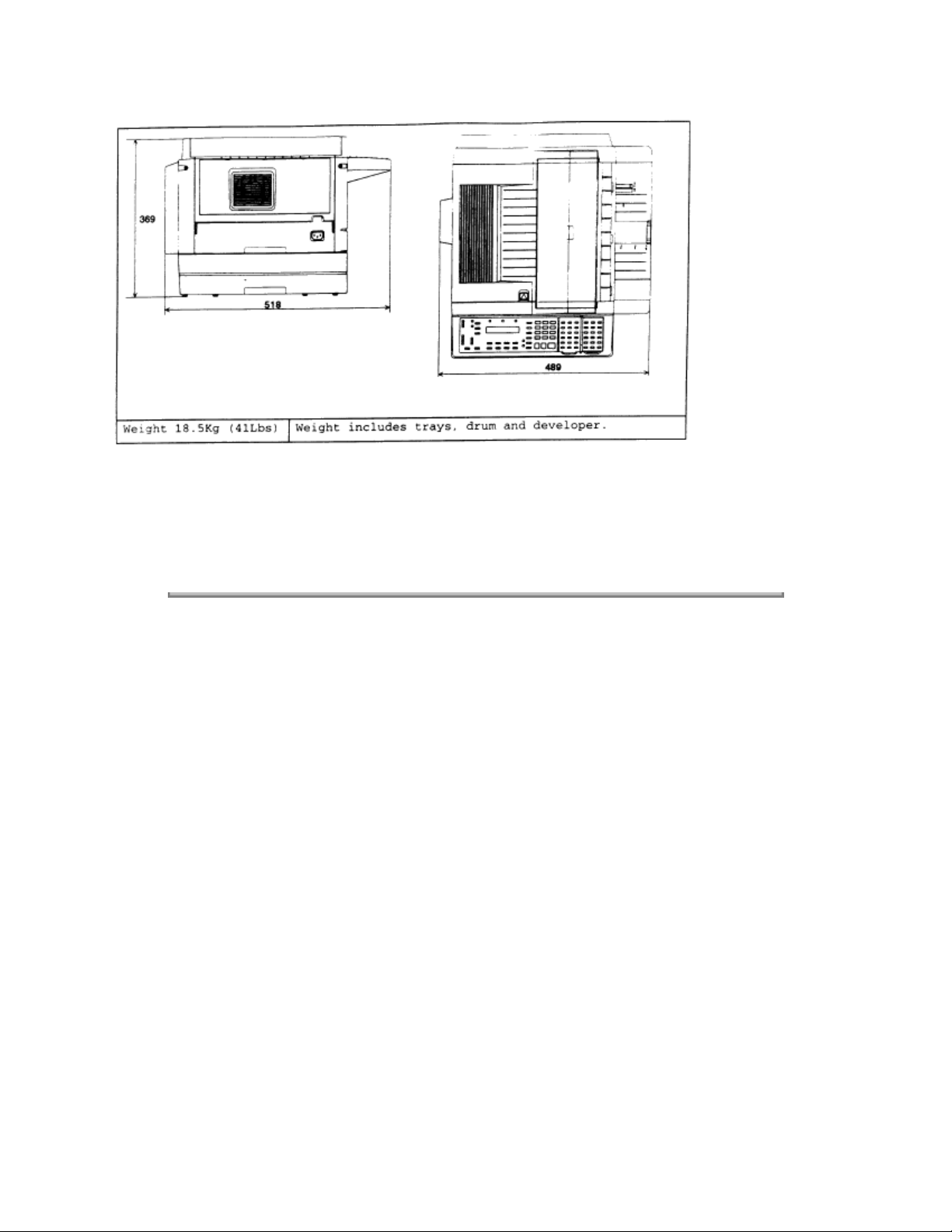
Environmental conditions Ambient temperature: 10 °C to 35 °C (50 to 95 degrees F)
Relative humidity: 35 % to 80 % with no condensation
Weight 18.5Kg (41Lbs) Weight includes trays, drum and developer.
Specifications / Comments
ITU-T T.4 and T.30
automatic fallback per ITU-T, V.17, V33, V.29, V.27ter, and
V21. Control signal speed is 300 bps.
Transmit and receive
Buffer capacity: 64 KB
Vertical: S.Fine 15.4 l/mm (392 lpi), Hyperfine 11.55 l/mm
(293 lpi), Fine 7.7 l/mm (196 lpi), Normal 3.85 l/mm (98 lpi)
Max: 280 mm (W) x 900 mm (L) (11 x 35 in)
Min: 148 mm (W) x 105 mm (L) (5.8 x 4.1 in)
Two or more sheets
Max: 257 mm (W) x 365 mm (L) (10.1 x 14.4 in)
Min: 148 mm (W) x 105 mm (L) (5.8 x 4.1 in)
Legal : 216 mm (W) x 356 mm (L) (8.5 x 14 in)
Letter : 216 mm (W) x 279 mm (L) (8.5 x 11 in)
500 sheets
Transmit: 363 W (Memory transmit)
Receive: 373 W
Copy: 372 W
Maximum: 396 W (Copying a solid black image)
Lithium Battery Precautions:
There is a danger of an explosion if the battery is installed incorrectly. Replace the battery with the
equivalent type. Discard used batteries according to the battery manufacturer's instructions. OKIDATA
does not recommend the independent replacement of this battery. The battery is sold only as a
component part of the main control PCB and cannot be purchased separately from OKIDATA.
Copyright 1997, Okidata, Division of OKI America, Inc. All rights reserved. See the OKIDATA Business
Partner Exchange (BPX) for any updates to this material. (http://bpx.okidata.com)

Page: 3
Service Manual for OF5800
Chapter 1 General Description
Feature
Display LCD: 2 line, 20 characters per line.
Transmit Terminal Identifier
(TTI)
Subscriber ID Numeric, up to 20 characters
AutoDial 200 total; 140 speed dial, 60 one-touch.
Telephone index Select AutoDial entries in LCD by Location ID name.
Redial Auto redial in fax mode, programmable for 2 to 5 attempts at 3 , 4
Cover page Cover page shows date and time, sender's name and fax number,
Delayed transmission Up to 20 delayed transmissions; programmable up to 31 days in
Relay broadcast Initiation up to 10 locations and hub abilities up to 10 groups
Broadcast Up to 209 locations
Group Communication Allows multiple broadcast or polling locations to be placed in up to
Polling Transmit from memory or receive; Standard polling, delayed polling
SecureMail Transmit and receive (10 mailboxes for receiving, 4 digit passcode)
Batch Transmission 5 boxes with a location ID of 16 characters. 40 files per box.
Security Transmission Compares the last 4 numbers of the dialed fax number to the last 4
Receive mode Tel ready, Fax ready. Select by pressing the receive key
Auto answer In Fax ready mode, select 1 to 9 rings. (Requires optional handset
Block junk fax Ability to reject "junk fax" receptions
Remote diagnostics Available
Second telephone jack For connecting Telephone Answering Device (TAD) or second
On-hook dialing Provides hands-free dialing for voice calls.
Hold Melody: Not Available
Call request During sending or receiving, a voice conversation can be initiated
Copy mode Single or multiple copies; up to 99, with sorting
Distinctive ring detection Ability to answer on specific ring patterns. User selectable
Comment
language: English, French, Spanish and Portuguese.
Alphanumeric or symbol, up to 22 characters
12 programmable one-touch
(Up to 40 digits per location; 16 characters per location ID)
or
5 minute intervals; manual last-number redial.
and a 40-character user-programmable message.
advance.
(This is a proprietary function)
32 call groups. Up to 200 locations can be placed in a group. Group
0 includes all AutoDial locations.
programmable up to 31 days in advance, database polling (10 files,
4 digit file number) (This is a proprietary function)
Programmable up to 24 hours per box.
digits of the subscriber ID.
for ring)
phone.
Holding time: 5 minutes (works only if the handset is attached)
on the same call after each page is printed.

Automatic reduction Automatically reduces incoming documents to fit on receive paper
Manual settings: 100%, 97%, 91%, 81%, 75%.
Half page reception Combines half page fax messages onto a single page.
Out of paper reception Receives up to 25 communications to memory if a Paper-Out,
Toner-Out, or Cover Open condition exists.
Closed network Proprietary network option
Silent operation Disables the Operation Complete tone
Confirmation stamp Stamps transmit document while feeding.
Copyright 1997, Okidata, Division of OKI America, Inc. All rights reserved. See the OKIDATA Business
Partner Exchange (BPX) for any updates to this material. (http://bpx.okidata.com)

Page: 4
Service Manual for OF5800
Chapter 1 General Description
Report
User settings list Prints current machine settings as programmed by the user.
One-touch dial list Prints numbers stored in the one-touch keys.
Speed dial list Prints phone numbers stored in speed dial locations.
Program one-touch list Prints numbers stored in programmable one-touch keys.
Group number list Prints groups stored in the autodialer.
Function list Prints a program mode list showing user programming tree.
T.30 monitor Prints a diagnostic procedural summary of the last fax
Confirmation Report Transmit Confirmation Report (TCR) or Receive Confirmation
Activity journal Prints a cumulative total of the last 50 transmissions or receptions;
Cover page Transmit cover page showing date, receiver’ s and sender’ s
SecureMail box list SecureMail boxes with owners’ names.
SecureMail reception
message
Batch transmission box list Batch transmission boxes stored with remote fax number and
Batch transmission
document
Command list Shows the delayed and pending commands.
Power failure report Prints if any documents in memory were erased due to power
Check message Prints if communication error occurs; accompanied by audible
Description
communication; used for technical diagnostics.
Report (RCR); User selectable on/off.
user selectable as manual or automatic.
names, and a 40-character user-programmable message.
Notifies mailbox owners of SecureMail receptions.
transmit starting time
Print the documents stored in the batch transmission box
failure
alarm.
Copyright 1997, Okidata, Division of OKI America, Inc. All rights reserved. See the OKIDATA Business
Partner Exchange (BPX) for any updates to this material. (http://bpx.okidata.com)

Page: 5
Service Manual for OF5800
Chapter 1 General Description
Item
Scanning resolution Horizontal: 12 dots/mm (304.8 dpi)
Scanning area Top of Page: -2mm +/- 4mm
Scanning reference point Center of page
Document Contrast Compensation for normal, dark, or light documents
Grayscale 64 level grayscale (Diffusion and Dither)
Document feeder capacity 50 sheets of 20lb bond paper
Original document feeding
direction
Document scan time Normal: 1.7 sec/page
Primary Resolution Normal, Fine, Sfine, or Grayscale; user selectable
Document Skew +/- 1%
Copyright 1997, Okidata, Division of OKI America, Inc. All rights reserved. See the OKIDATA Business
Partner Exchange (BPX) for any updates to this material. (http://bpx.okidata.com)
Specifications / Comments
Vertical: 15.4, 11.55, 7.7, 3.85 lines/mm
Bottom of Page: +/- 3mm
Face up
Fine: 3.4 sec/page
Sfine: 6.8 sec/page

Page: 6
Service Manual for OF5800
Chapter 1 General Description
Item
Printing resolution Laser diode beam scanning
Printing method One-component non-magnetic toner xerographic printer
Developer One-component developer
Fusing method Heat roller
Toner yield Starter kit: 3,600 pages
Print area Top margin: 4 mm
Printer reference Left margin
Paper cassette capacity Paper cassette: 500 sheets, letter only
Receive paper tray capacity 100 sheets
Auto reduction rate 97.5% to 70% at 2.5% intervals when auto reduction is selected.
Printer warm up time Under 40 seconds (when in Power Save Mode)
Copyright 1997, Okidata, Division of OKI America, Inc. All rights reserved. See the OKIDATA Business
Partner Exchange (BPX) for any updates to this material. (http://bpx.okidata.com)
Specifications / Comments
Horizontal: Fax 609.6 dpi
Vertical: Fax 586.7 dpi
Supply kit: 5,500 pages
* All yields are based on 4% document coverage.
Bottom margin: 4 mm
Multi-purpose tray: 150 sheets, letter or legal

Page: 7
Service Manual for OF5800
Chapter 1 General Description
Item
Specifications / Comments
Document Memory 1 Megabyte - 78 pages
Optional memory upgrade: Up to three, 2 MB upgrades can be
installed for a total of 6 MB. (each 2 MB upgrade provides an
additional 160 pages)
Document memory backup Standard Memory: 108 hours
with one upgrade card
with two upgrade cards installed: 36 hours
with three upgrade cards installed: 27 hours
Programmable data memory
backup (SRAM)
Lithium Battery: 5 year life
Contents: All programmable machine parameters
Memory usage indication LCD during document storage
Copyright 1997, Okidata, Division of OKI America, Inc. All rights reserved. See the OKIDATA Business
Partner Exchange (BPX) for any updates to this material. (http://bpx.okidata.com)

Page: 8
Service Manual for OF5800
Chapter 1 General Description
Item
Drum Cartridge 20,000 pages based on 4% document coverage
Toner Cartridge Starter: 3,600 pages
Transfer unit 50,000 pages
Fuser unit 50,000 pages
Copyright 1997, Okidata, Division of OKI America, Inc. All rights reserved. See the OKIDATA Business
Partner Exchange (BPX) for any updates to this material. (http://bpx.okidata.com)
Specifications / Comments
Supply: 5,500 pages
* All yield based on 4% document coverage

Page: 9
Service Manual for OF5800
Chapter 2 Machine Operations
To be provided at a later time.
Copyright 1997, Okidata, Division of OKI America, Inc. All rights reserved. See the OKIDATA Business
Partner Exchange (BPX) for any updates to this material. (http://bpx.okidata.com)
Page: 10
Service Manual for OF5800
Chapter 2 Machine Operations
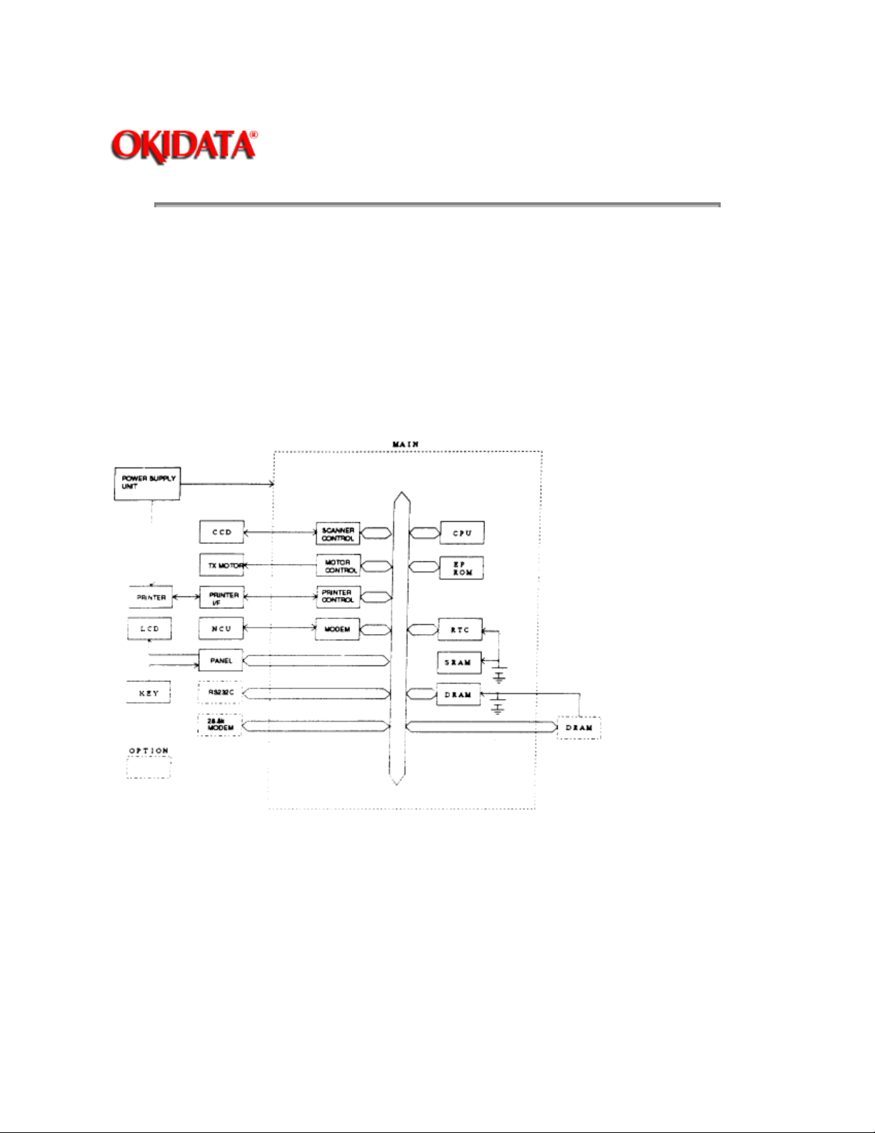
The main control PCB controls the operations of all machine functions. Jumper JP1 on the main control
PCB controls the data memory back-up. Memory data that is backed-up in the event of a power failure
includes any stored documents.
Jumper JP2 on the main control PCB controls the programmable data memory back-up. Memory data that
is backed-up in the event of a power failure includes user programmed information such as the date, time,
TTI, autodialer, memory switches, etc. If the Passcode is forgotten, removing JP2 will clear all User
Settings.
NOTE:
boards.
JP1, JP2, should remain in the "ON" position at all times. Be sure to check this on all replacement
Main control PCB block diagram
The main control unit controls all function of the machine. Following are its components:
Fax Engine
CPU --
Scanner Control
Modem -
The CPU is the core of the control section. It controls all other sections.
--- Processes the signal from the Charge Coupled Device (CCD).
-- The modem facilitates modulation and demodulation of data for fax communication.

Memory (EPROM, SRAM, DRAM)
EPROM
SRAM
information.
DRAM
being a buffer.
Copyright 1997, Okidata, Division of OKI America, Inc. All rights reserved. See the OKIDATA Business
Partner Exchange (BPX) for any updates to this material. (http://bpx.okidata.com)
-- - The EPROM contains all program instructions for unit operation.
--- The SRAM, which is backed-up by a lithium battery, is used to store user programmed
--- The DRAM, which is backed-up by a battery, is used to store memorized documents along with
Page: 11
Service Manual for OF5800
Chapter 2 Machine Operations
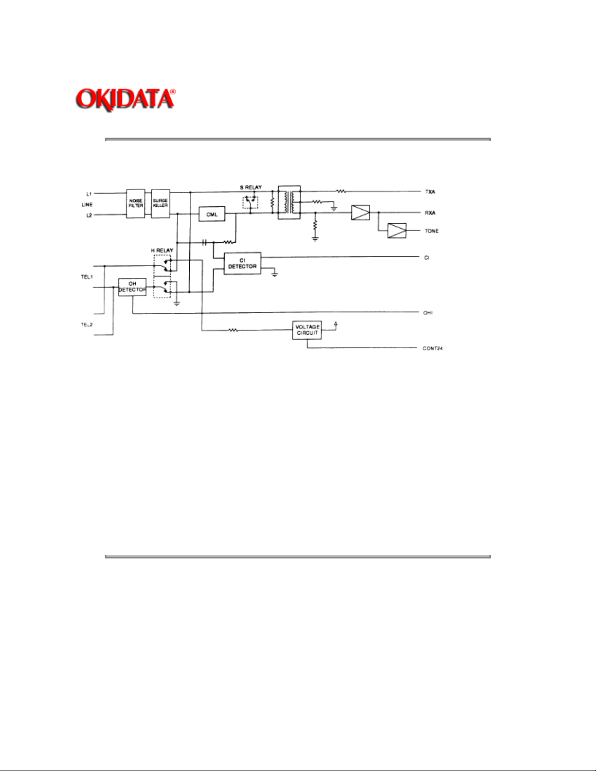
The NCU PCB provides the connection to the telephone line. It consists of the interface circuit, dial pulse
generator, ring signal detection and telephone control circuit.
NCU PCB block diagram
Major components of the NCU
CML relay
S relay
OH detector
H relay
CI Detector
Voltage Circuit
Copyright 1997, Okidata, Division of OKI America, Inc. All rights reserved. See the OKIDATA Business
Partner Exchange (BPX) for any updates to this material. (http://bpx.okidata.com)
- Connects the telephone line to the phone or fax. (CML means Connect Machine to Line)
- Used to send dial pulse signals in pulse dialing.
- Detects the On-hook condition of the second telephone unit.
- Connects the Tel1 and Tel2 lines to the fax machine.
- A photo coupler that detects an incoming ring. (CI means Call Indicator)
- Supplies 24 volts to the relays
Page: 12
Service Manual for OF5800
Chapter 2 Machine Operations
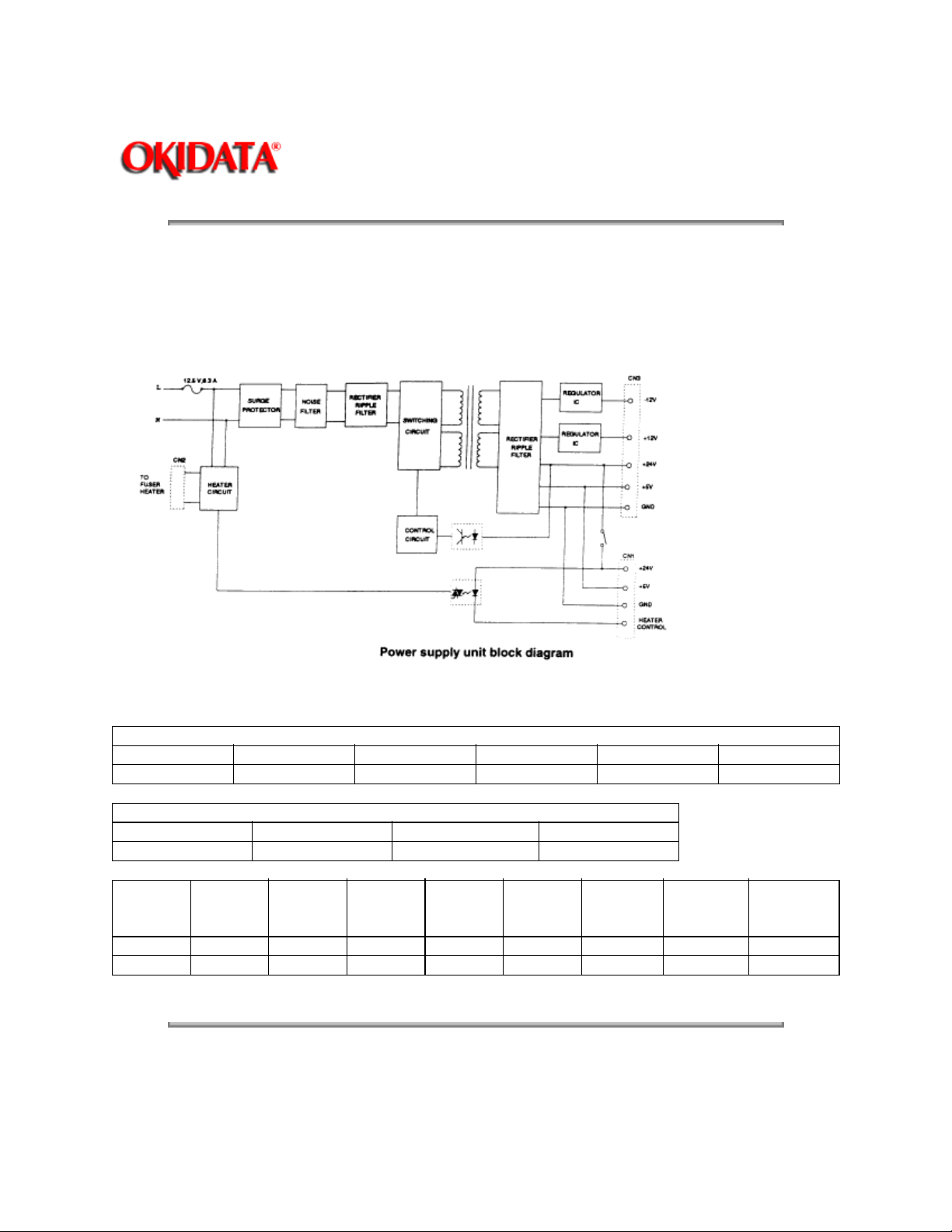
The power supply unit receives the input line voltage and converts it to output voltages of +5 VDC, +24
VDC,+12 VDC, and -12 VDC.
If an over current condition is sensed in the secondary circuit, power is interrupted.
The power supply unit has three output connectors. The following table shows the connector outputs: CN1
to the Printer Mechanical Control PCB, CN2 to the Fuser Heater, and CN3 to the Main Control PCB.
CN1 Printer Mechanical Control PCB
Pin No. 1 2 3 4 5
Output +24V GND GND +5V H.L
CN2 Fuser
Pin No. 1 2 3
Output N N.C L
CN3 Main
Control
PCB
Pin No. 1 2 3 4 5 6 7 8
Output +24V +24V GND GND +12V -12V +5V +5V
Image and programmed data is backed-up in the event of a power failure.
Copyright 1997, Okidata, Division of OKI America, Inc. All rights reserved. See the OKIDATA Business
Partner Exchange (BPX) for any updates to this material. (http://bpx.okidata.com)

Page: 13
Service Manual for OF5800
Chapter 2 Machine Operations
The CCD (Charge Coupled Device) includes the photo sensitive device, charge transfer registers and
output stage. The photo sensitive device is a MOS capacitor. It receives light which is reflected from the
surface of the document through the lens and converts the received light energy into a series of electrical
signals. These signals are then stored as a charge. The charge transfer registers send the signals
sequentially to the output stage which converts them into appropriate voltages representing black and
white images.
The output stage sends voltages to the Main Control PCB for further processing.
Copyright 1997, Okidata, Division of OKI America, Inc. All rights reserved. See the OKIDATA Business
Partner Exchange (BPX) for any updates to this material. (http://bpx.okidata.com)

Page: 14
Service Manual for OF5800
Chapter 2 Machine Operations
2.6.1 Sensor Locations
2.6.2 Sensor Descriptions
Copyright 1997, Okidata, Division of OKI America, Inc. All rights reserved. See the OKIDATA Business
Partner Exchange (BPX) for any updates to this material. (http://bpx.okidata.com)
Service Manual for OF5800
Chapter 2 Machine Operations
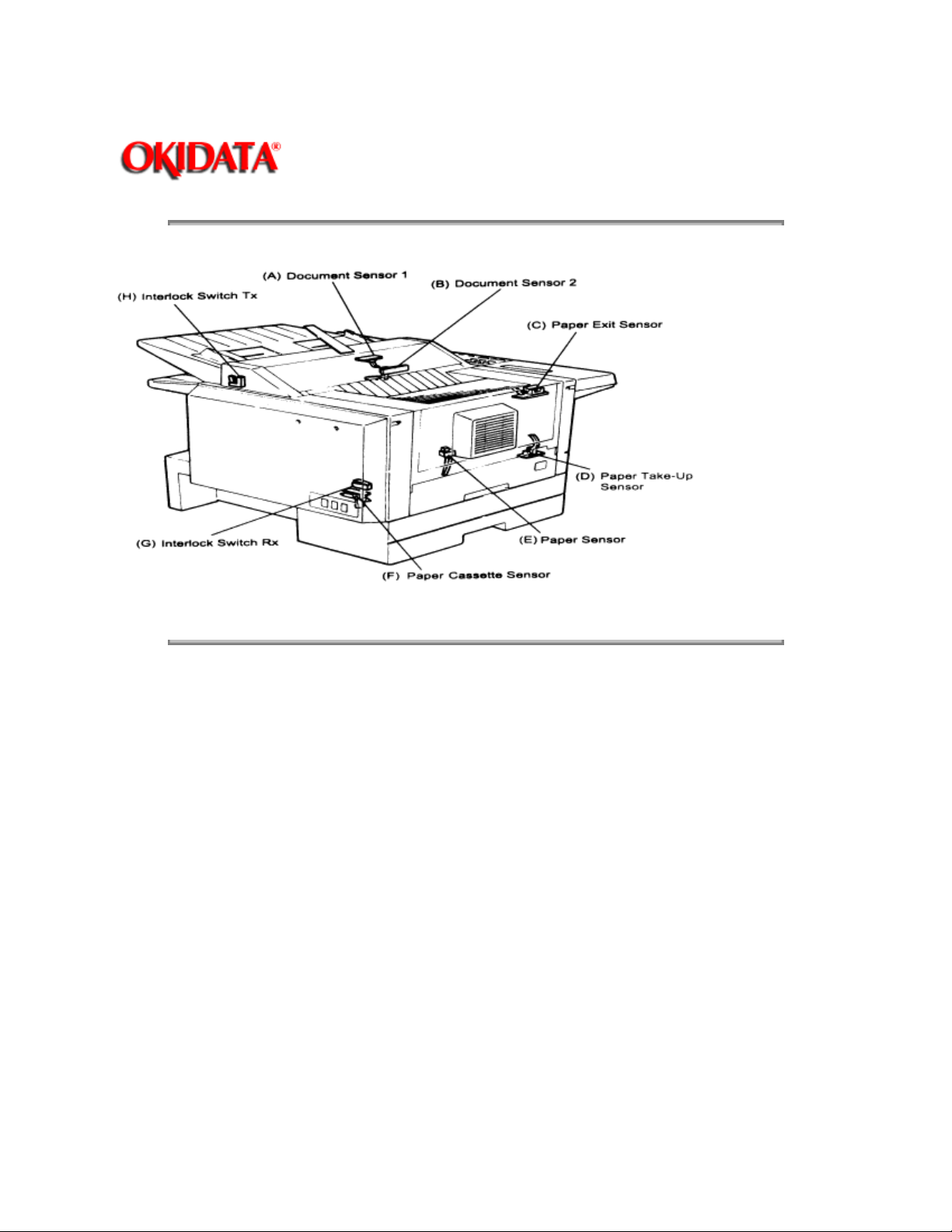
The following illustration shows the relative positions of the machine's sensors
Page: 15
Copyright 1997, Okidata, Division of OKI America, Inc. All rights reserved. See the OKIDATA Business
Partner Exchange (BPX) for any updates to this material. (http://bpx.okidata.com)

Page: 16
Service Manual for OF5800
Chapter 2 Machine Operations
The following table gives a brief description of each sensor and its function.
Sensor Code Sensor Type Detects
A
Document Sensor 1 DS1 Photo interrupter Presence of document in feeder
B
Document Sensor 2 DS2 Photo interrupter Leading and trailing edge of doc.
C
Paper Exit Sensor PC3 Photo interrupter Detects jam at paper exit.
D
Paper Sensor 2 PC1 Photo interrupter Detects paper feeding out of
tray/cassette
E
Paper Sensor PS Photo interrupter Presence of paper in tray
F
Paper Sensor/Cassette
Sensor/
G
Rx Interlock RXIL Micro switch Printer cover open
H
Tx Interlock TXIL Micro switch Scanner cover open
Copyright 1997, Okidata, Division of OKI America, Inc. All rights reserved. See the OKIDATA Business
Partner Exchange (BPX) for any updates to this material. (http://bpx.okidata.com)
PS/C Photo interrupter Presence of recording paper
Page: 17
Service Manual for OF5800
Chapter 2 Machine Operations
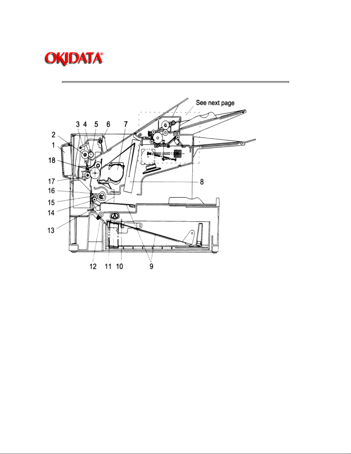
1. Fan Motor
2. Lower Fusing Roller
3. Paper Exit Sensor
4. Heater Lamp
5. Upper Fusing Roller
6. Paper Exit Roller
7. Toner Cartridge
8. Print Head Unit
9. Paper Lift-Up Plate
10. Paper Cassette Sensor
11. Paper Pick-up Roller
12. Paper Feed Roller
13. Paper Sensor
14. Paper Transfer Roller
15. Paper Take-up Sensor
16. Paper Take-up Roller (Tray)
17. Image Transfer Roller
18. Drum Cartridge

Copyright 1997, Okidata, Division of OKI America, Inc. All rights reserved. See the OKIDATA Business
Partner Exchange (BPX) for any updates to this material. (http://bpx.okidata.com)

Page: 18
Service Manual for OF5800
Chapter 2 Machine Operations
2.8.1 Document Detection
2.8.2 Document Separation
2.8.3 Document Transport
2.8.4 Document Scanning
2.8.5 Document Discharge
Copyright 1997, Okidata, Division of OKI America, Inc. All rights reserved. See the OKIDATA Business
Partner Exchange (BPX) for any updates to this material. (http://bpx.okidata.com)

Page: 19
Service Manual for OF5800
Chapter 2 Machine Operations
When a document is placed into the document feeder, Document Sensor 1 (DS1) is activated.
Copyright 1997, Okidata, Division of OKI America, Inc. All rights reserved. See the OKIDATA Business
Partner Exchange (BPX) for any updates to this material. (http://bpx.okidata.com)
 Loading...