

Okidata OKIFAX 5900, OKIFAX 5700 Service Manual

OKIFAX 5700/5900
Maintenance Manual
Second Edition
Note: Throughout this manual there are many references to the
G4/ISDN option. This option is not available in the U.S. or
CANADA.
October, 1999
Oki Data Corporation

Contents
CHAPTER 1 GENERAL INFORMATION
1. GENERAL INFORMATION ...................................................................... 1-1
1.1 General Performance .............................................................................. 1-1
1.2 General User’s Functions ........................................................................ 1-4
1.3 General Maintenance Functions .............................................................. 1-7
1.4 General Appearance................................................................................ 1-9
1.5 Basic Performance Specifications ........................................................... 1-11
1.6 Reports and Lists..................................................................................... 1-21
CHAPTER 2 INSTALLATION PROCEDURE
A. Setup Information .................................................................................... 2-1
2.1 General .................................................................................................... 2-1
2.2 Site Selection........................................................................................... 2-3
2.3 Unpacking................................................................................................ 2-5
2.4 Contents Identification ............................................................................. 2-7
2.5 Installation of Attachments....................................................................... 2-8
2.6 AC Cord Connection................................................................................ 2-13
2.7 Telephone and Line Connection .............................................................. 2-14
2.8 Pcking for Shipment................................................................................. 2-14
B. Programming and Initial Settings ............................................................. 2-15
2.9 Initial Settings .......................................................................................... 2-15
2.9.1 General Procedure of Key Operation ................................................................... 2-15
2.9.2 Technical Functions: Setup .................................................................................. 2-21
2.9.2.1 Technical Functions Operation 1.......................................................................... 2-22
2.9.2.2 Technical Functions Operation 2.......................................................................... 2-23
2.9.2.2.1 T1 (TX) Timer Value ............................................................................................. 2-30
2.9.2.2.2 T1 (RX) Timer Value............................................................................................. 2-31
2.9.2.2.3 T2 Timer *100ms.................................................................................................. 2-32
2.9.2.2.4 Error Criterion ...................................................................................................... 2-33
2.9.2.2.5 Attenuator ............................................................................................................ 2-33
2.9.2.2.6 T/F Tone Att.......................................................................................................... 2-34
2.9.2.2.7 MF Att................................................................................................................... 2-34
2.9.2.2.8 Ring Dura. *10ms................................................................................................. 2-35
2.9.2.2.9 CML Timing *100ms ............................................................................................. 2-35
2.9.2.2.10LED Headstrobe .................................................................................................. 2-36
2.9.2.3 Technical Functions (Setup)................................................................................. 2-37
2.9.2.4 TEL/FAX automatic switching .............................................................................. 2-48
2.9.2.5 TAD mode ............................................................................................................ 2-50
2.9.2.6 Outline of Parallel Pick Up ................................................................................... 2-52
2.9.3 User’s Functions .................................................................................................. 2-54
2.9.4 Location Program................................................................................................. 2-56
2.9.4.1 Select Menu is shown as below: ......................................................................... 2-56
2.9.5 Setup.................................................................................................................... 2-60
2.9.5.1 Clock Adjustment ................................................................................................. 2-62
2.9.5.2 ID/Passward Programming: ................................................................................. 2-63
2.9.5.2.1 TSI/CSI ................................................................................................................ 2-64
2.9.5.2.2 Sender ID............................................................................................................. 2-65
2.9.5.3 Machine Settings: ................................................................................................ 2-69
2.9.5.3.1 Auto Answer Mode ............................................................................................... 2-73
1

2.9.5.3.2 TX Mode Default .................................................................................................. 2-74
2.9.5.4 Dial Options: ........................................................................................................ 2-80
2.9.5.4.1 Redial Tries .......................................................................................................... 2-83
2.9.5.4.2 Redial Interval ...................................................................................................... 2-84
2.9.5.4.3 Dial Prefix............................................................................................................. 2-85
2.9.5.5 Incoming Options: ................................................................................................ 2-89
2.9.5.5.1 CNG COUNT ....................................................................................................... 2-91
2.9.5.5.2 Distinctive Ring .................................................................................................... 2- 92
2.9.5.6 Report Options:.................................................................................................... 2-96
2.9.5.7 LAN Options:........................................................................................................ 2-98
2.9.5.7.1 IP Address............................................................................................................ 2-99
2.9.5.7.2 Subnet Mask ........................................................................................................ 2-101
2.9.5.7.3 Default Gateway .................................................................................................. 2-102
2.9.6 User Default Setting ............................................................................................. 2-105
2.9.7 Technical Default Setting...................................................................................... 2-106
2.9.8 Default Setting of Dial Parameters ....................................................................... 2-107
2.9.9 Off-line Tests ........................................................................................................ 2-108
2.9.9.1 Self Diagnosis Flow.............................................................................................. 2-109
2.9.10 On-line Tests ........................................................................................................ 2-113
2.10 Installation of optional units...................................................................... 2-116
2.10.1 Optional units ....................................................................................................... 2-116
2.10.2 Memory Board Installation Instruction .................................................................. 2-117
2.10.3 Network Card Installation Instruction.................................................................... 2-118
2.10.4 G4 Board Installation Instruction .......................................................................... 2-119
CHAPTER 3 BRIEF TECHNICAL DESCRIPTION
3.1 Fundamentals of the Electro-Photographic Process................................ 3-2
3.2 Actual Electo-photographic Process ........................................................ 3-4
3.3 Boards and Units ..................................................................................... 3-5
3.4 Overall Dimension and Mechanical Structure of OKIFAX 5700/5900...... 3-6
CHAPTER 4 MECHANICAL DISASSEMBLY AND REASSEMBLY
4. General .................................................................................................... 4-1
4.1 Precautions for Parts Replacement ......................................................... 4-1
4.2 Tools ........................................................................................................ 4-3
4.3 How to Disassemble and Reassemble .................................................... 4-3
4.3.1 Document Table Cover......................................................................................... 4-6
4.3.2 Rear Cover and NCU Cover ................................................................................ 4-6
4.3.3 Main Cover........................................................................................................... 4-7
4.3.4 Operation Unit...................................................................................................... 4-9
4.3.5 NCU Board........................................................................................................... 4-10
4.3.6 MODEM Board..................................................................................................... 4-10
4.3.7 Plate Package...................................................................................................... 4-11
4.3.8 Scanner Unit (CIS) ............................................................................................... 4-12
4.3.9 Stacker Frame ..................................................................................................... 4-13
4.3.10 Printer Unit ........................................................................................................... 4-13
4.3.11 Fan ....................................................................................................................... 4-14
4.3.12 Main Board........................................................................................................... 4-15
4.3.13 Contact Assembly and High-/Low-voltage Power Supply Boards ........................ 4-15
4.3.14 Disassembling the Operation Unit........................................................................ 4-16
4.3.14.1 Disassembling the Operation Unit........................................................................ 4-18
4.3.15 Disassembling the Scanner Unit (L)..................................................................... 4-19
4.3.16 Scanner (CIS) ...................................................................................................... 4-20
4.3.17 PC1/PC2 Sensors ................................................................................................ 4-20
4.3.18 Speaker................................................................................................................ 4-21
4.3.19 Scanner Motor ..................................................................................................... 4-22
2

4.3.20 Disassembling the Printer Unit............................................................................. 4-23
4.3.21 LED Head ............................................................................................................ 4-24
4.3.22 Toner Lookout Board............................................................................................ 4-25
4.3.23 Stacker Cover ...................................................................................................... 4-26
4.3.24 Fusing Unit........................................................................................................... 4-26
4.3.25 Manual Feed Assembly........................................................................................ 4-26
4.3.26 Back-up Roller, Transfer Roller ............................................................................ 4-27
4.3.27 Resist Roller, Hopping Roller, Sensor Plates ....................................................... 4-28
4.3.28 Ink Jet Guide Assembly........................................................................................ 4-29
CHAPTER 5 ADJUSTMENTS
5.1 Setting of LED Print Head Drive Time...................................................... 5-1
5.2.1 Confirmation Items ............................................................................................... 5-2
5.2.2 Measurement ....................................................................................................... 5-3
CHAPTER 6 CLEANING AND MAINTENANCE
6.1 Replacement of Consumable................................................................... 6-1
6.2 Routine Inspection ................................................................................... 6-3
6.3 Printer Counter Display/Clear .................................................................. 6-5
6.4 Printer Counter Display/Clear .................................................................. 6-7
6.5 Self-diagnosis Test................................................................................... 6-8
6.6 Sensor Calibration Test............................................................................ 6-11
6.7 LEDs Test ................................................................................................ 6-12
6.8 Tone Send Test ........................................................................................ 6-13
6.9 High-speed Modem Send Test................................................................. 6-14
6.10 High-speed Modem Receive Test ............................................................ 6-15
6.11 MF Send T est........................................................................................... 6-16
6.12 Tone (TEL/FAX) ....................................................................................... 6-17
6.13 Protocol Dump Data Printing ................................................................... 6-18
6.14 System Reset .......................................................................................... 6-19
6.15 Service Codes ......................................................................................... 6-20
6.16 G4 Service Code Lists ............................................................................. 6-23
CHAPTR 7 TROUBLESHOOTING AND REPAIR FOR OKIFAX 5700/5900
7.1 Overall Troubleshooting Flow Chart......................................................... 7-2
7.2 No LCD Operation ................................................................................... 7-3
7.3 Alarm LED On.......................................................................................... 7-4
7.4 Printing Test Failure ................................................................................. 7-5
7.5 No Local Copy ......................................................................................... 7-6
7.6 Auto Dial Failure ...................................................................................... 7-7
7.7 Transmission Problem ............................................................................. 7-8
7.8 Auto Reception Failure ............................................................................ 7-10
7.9 Reception Problem .................................................................................. 7-11
7.10 Sensor Calibration Test............................................................................ 7-13
7.11 LED Test .................................................................................................. 7-14
7.12 Tone Send Test ........................................................................................ 7-15
7.13 High-speed Modem Test .......................................................................... 7-16
7.14 MF Send Test........................................................................................... 7-18
7.15 Tone (TEL/FAX) Send Test ...................................................................... 7-19
7.16 No Acoustic Line Monitor ......................................................................... 7-20
7.17 Power Supply Unit ................................................................................... 7-21
3

7.18 No Document Feeding ............................................................................. 7-22
7.19 Multiple Document Feeding ..................................................................... 7-23
7.20 Document Skew....................................................................................... 7-24
7.21 Document Jam......................................................................................... 7-26
7.22 Printer Unit ............................................................................................... 7-27
7.22.1 Precautions .......................................................................................................... 7-27
7.22.2 Troubleshooting Flow Charts of Printer Unit......................................................... 7-28
Appendix A PC Board Decriptions and Operation
A1.1 Unit Configuration and Block Diagram ................................................................. A1-1
A2.1 OKIFAX 5700/5900 Signal Flow........................................................................... A2-1
A2.2 Explanation of Signal Flowchart........................................................................... A2-18
A3.1 MCNT................................................................................................................... A3-1
A3.2 OPE Control......................................................................................................... A3-36
A3.3 MODEM C34 PC Board ....................................................................................... A3-37
A3.4 UNC, WN5, FN5 and DN5 Circuit Diagram.......................................................... A3-42
A3.5 Power Supply Board ............................................................................................ A3-55
A3.6 High-voltage Power Supply Circuit....................................................................... A3-57
A3.7 G4A-PCB ............................................................................................................. A3-59
Appendix B Description of Print Operations for OKIFAX 5700/5900
B.1 Mechanical Components...................................................................................... B-1
B.2 Description of Print Operation .............................................................................. B-3
B.3 Errors ................................................................................................................... B-14
B.4 Other Special Cases ............................................................................................ B-20
Appendix C Not used at this time
Appendix D Mechanical Expanded View Drawing and Parts List
(OKIFAX 5700/5900)
Appendix E Not used at this time
Apeendix F Not used at this time
Appendix G PC-Loading
Appendix H RMCS System Manual (For Model 30)
4

CHAPTER 1
GENERAL INFORMATION

1. GENERAL INFORMATION
1.1 General Performance
(1) Type of appearance
• Desktop type
(2) Applicable lines
• PSTN (Public switched telephone network
• PBX (Private branch exchange) telephone line
• ISDN (Integrated service digital network)
• LAN (Local area network)
Note: ISDN and LAN are option.
(3) Compatibility
• ITU-T Group 3 facsimile transceiver
• ITU-T Group 4 facsimile transceiver (option)
(4) Document width
• Max. 216 mm (NA Letter)
• Min. 148 mm (ISO A5 size)
(5) Effective reading width
TX • 215.4 mm (NA Letter) COPY • 211.3 mm (NA Letter)
• 208.6 mm (ISO A4 size) • 211.3 mm (ISO A4 size)*1
(6) Scanning length
• 128 mm to 356 mm
Length setting: Long documents (1500 mm) are also available.
* Printing width will be 206 mm.
(7) Automatic document feeder (ADF)
• 50 sheets (NA Letter/A4-size: 20-lb/75gm Oki Data recommended paper)
• 30 sheets (NA Letter/A4-size: 16 to 28-lb/60 to 105gm)
(8) Recording paper
• 1st cassette: NA Letter/NA Legal/A4-size plain paper cut 250 sheets capacity
(20-lb/75gm)
• 2nd cassette (option): NA Letter/NA Legal/A4-size plain paper cut 500 sheets capacity
(20-lb/75gm)
• Manual paper feeder: Transparency for overhead projector, applicable.
Sheet size: NA Letter/NA Legal/A4-size
*: Oki Data recommended paper
(9) Printable width
• NA Letter: 211.3 mm (203.2 mm for assured quality)
• NA Legal: 211.3 mm (203.2 mm for assured quality)
• ISO A4: 206.0 mm (197.3 mm for assured quality)
(10) Printable length
• NA Letter: 273.4 mm (266.7 mm for assured quality)
• NA Legal: 349.6 mm (342.9 mm for assured quality)
• ISO A4: 291.0 mm (284.3 mm for assured quality)
(11) Copy stacker
• Face down stacking: Max. 200* sheets
• Face up stacking: Max. 10* sheets
*Note 1: Oki Data recommended paper
Note 2: Face down or face up stacking is changeable by the lever.
OKIFAX 5700/5900
1 - 1

(12) Scanning resolution
a) Horizontal:
• 300 dot per inch
Note: 600 dpi x 15.4 mm; copy is available.
b) Vertical:
• 300 dot per inch, 15.4, 7.7, and 3.85 lines per mm
Note: 300 dpi x 300 dpi; Transmission is available.
(13) Scanning method
• 2592 bits contact image sensor
(14) Recording resolution
a) Horizontal:
• 600 dot per inch
b) Vertical:
• Variable:
STD
Fine
Ex-Fine (15.4 line/mm)
Ex-Fine (300 dot/inch)
• Fixed EX-FINE mode : 300 dot/inch, 15.4 line/mm
FINE mode : 7.7 line/mm
STD mode : 3.85 line/mm
PC-Print : 600 dot/inch, 300 dot/inch
A4
3.85 ~ 4.96
7.7 ~ 9.93
15.4 ~ 19.87
300 ~ 387
Letter
3.85 ~ 5.28
7.7 ~ 10.57
15.4 ~ 21.15
300 ~ 412
(15) Printing method
Electro photographic printing
• 211.3 mm (4992 bits) LED print head
(16) Minumum scan line time for reception
• When receiving from OKIFAX or ECM: 0 ms
• When receiving from non OKIFAX and non ECM: 10 ms at 3.85 line/mm
5 ms at 7.7 line/mm, 15.4 line/mm
(17) Print speed
• Max. 10 sheets per minute (at NA letter size)
(18) Coding scheme
• Modified Huffman (MH)
• Modified Read (MR)
• Modified Modified Read (MMR)
• JBIG (only for OKIFAX 5900)
(19) Modem
• ITU-T Rec. V.29: 9600bps for use on point-to-point 4-wire leased telephone type
circuit.
• ITU-T Rec. V.27 ter: 4800bps modem for use in GSTN (General Switched Telephone
Network)
• ITU-T Rec. V.21 channel 2: 300 bps duplex modem for GSTN
• ITU-T Rec. V.17: 2-wire modem for fax applications up to 14.4kbps
• ITU-T Rec. V.34
(20) Transmission speed
• 2.5 sec. per sheet of ITU-T No.1 evalution test chart (for OKIFAX 5900)
• 3.0 sec. per sheet of ITU-T No.1 evalution test chart (for OKIFAX 5700)
Note: This is Phase C at 3.85 line/mm.
OKIFAX 5700/5900
1 - 2

(21) Protocol
• ITU-T Rec. T.30
• ITU-T Rec. G4 Class 1 (option)
• OKI special protocols: High speed protocol (G3)
(22) Error correction scheme
• ITU-T ECM
(23) Image memory
• Basic model: 2.5 M-byte (OKIFAX 5700)
4.5 M-byte (OKIFAX 5900)
• Optional memory: 2.0/4.0 M-byte
(24) Liquid crystal display (LCD)
• Four lines of 20 characters for operation guidance, check and various kinds of information
(25) Power source
• Normal input voltage 120 VAC for ODA version
• Normal input voltage 230 VAC for INT’L version
(26) MFP (Multi-Function Peripheral) function
PC Printer function
PC Scanner function
PC Fax Modem function
Note: For details, see “Product Specification for MFP”
Hardware is standard and software is option for Bi-Centro interface.
(27) ISDN function (option)
• G4 function
• ISDN G4: Communication
• ISDN G3: Communication
• ISDN: Report and List
Note: For details, see “Product Specification for ISDN G4 option”
(28) Network print service
• Netware
• TCP/IP
• Windows NT/95/3.1
• T600dpi, 10ppm
Note: For details, see “Product Specification for Network Print Service”
OKIFAX 5700/5900
1 - 3

1.2 General User’s Functions
1) Transmission
(1) Transmit mode
• Automatic transmit mode
• Manual transmit mode
(2) Instant Dialling
(3) Delayed feeder transmission
(4) Memory transmission
• 40 sessions
(5) Delayed memory transmission (within 3 days)
• 20 specified times for OKIFAX 5700
• 30 specified times for OKIFAX 5900
(6) Sequential broadcast (Memory)
• 150 stations for OKIFAX 5700
• 240 stations for OKIFAX 5900
(7) Delayed broadcast
• 20 specified times for OKIFAX 5700
• 30 specified times for OKIFAX 5900
(8) Confidential message transmission
• Feeder Confidential TX
• Memory Confidential TX
(9) Relay broadcast initiate
• Feeder Relay broadcast initiate
• Memory Relay broadcast initiate
(10) Polling transmission
• Feeder Polling TX
• Memory Polling TX
(11) Bulletin Poll transmission (When Box number is opened.)
• 16 boxes
(12) Batch transmission
(13) Priority transmission
(14) Transmission preparation (Feeder)
OKIFAX 5700/5900
1 - 4

2) Reception
(1) Receive mode
• Automatic receive mode
• Manual receive mode
• TEL/FAX receive mode
• TAD mode
• Memory receive mode
• PC receive mode
• Forwarding mode
(2) Memory only reception
(3) No toner/No paper reception (memory)
(4) Confidential message reception
• 16 mail boxes
(5) Fax forwarding for incoming call
(6) Fax forwarding for no toner/no paper reception
(7) Polling reception
3) Convenience
(1) Dual access
(2) Automatic redial
(3) Last number redial (Manual redial)
(4) Local copy of a document, including multiple copies
• 99 copies max.
(5) Sender identification (Sender ID)
(6) Personal identification (Personal ID)
(7) TSI/CSI: Local telephone number
(8) Acoustic monitor (only TX mode)
• 5 level selectable
(9) Automatic alternate selecting call
(FAX No. + FAX No. can be registerd in one-touch keys).
• OKIFAX 5700: Speed Dial (1 to 40) are assigned to one-touch keys.
• OKIFAX 5900: Speed Dial (1 to 80) are assigned to one-touch keys.
(10) Half-tone transmission (at FINE resolution)
• 64 scale gradations
(11) Page re-transmission (Only when memory TX mode)
(12) Distinguishing text from pictures
(13) Vertical reduction printing (Reduction rate is from 100% to xx%)
OKIFAX 5700/5900
Note: xx is Letter 72.8%, A4 77.5%
1 - 5

(14) Smoothing printing
In case of 8 dot/mm x 3.85 lines/mm ∅ 300 dot/inch x 784 lines/inch
(15) Auto dialing
• Speed dialing:
OKIFAX 5700; 1 to 140 (1 to 40 are assigned to one-touch keys.)
OKIFAX 5900; 1 to 230 (1 to 80 are assigned to one-touch keys.)
• Group dialing; 20 groups
• Keypad dialing
• Chain dialing
• Mixed dialing
(16) Real-time dialing
Dialing with off hook condition or when the HOOK key is pressed.
(17) Automatic pause signal insertion
(18) Local copy
(19) Telephone directory (Alpha/Location) dialing
(20) TEL/FAX automatic switching
(21) TAD mode (for external telephone answering device)
(22) Session number
(23) Time and date printing
(23) Closed user group (Direct mail rejection)
(24) Contrast and resolution control
(25) Key touch tone
(26) Printer counter display (For drum, toner, print, and scan)
(27) Quick scanning
(28) Time and date setting
(29) Language selection
• 2 languages (LCD and Report)
(30) Distinctive ring detect
(31) Restricted access
(32) Beep sound
4) Reports
(1) Function list
(2) Configuration
(3) Phone directory
OKIFAX 5700/5900
1 - 6

(4) Group directory
(5) Activity report
(6) Active memory files
(7) Broadcast MCF (Message Confirmation)
(8) Protocol dump (G3 and G4)
(9) NIC configuration
(10) Log. report
(11) G4 Log. report
(12) Self diagnosis report
5) Report options
(1) MCF. (Single-Loc.)
(2) MCF. (Multi-Loc.)
(3) Image in MCF.
(4) Error report (MCF.)
1.3 General Maintenance Functions
1) Local tests
(1) Self-diagnosis
Main board
• CPU ROM/RAM check
• Flash memory check (Program, Language, and Default)
• Modem
• RAM check
• Toner cartridge
• Option memory check
DEVICE ID
• LAN Board check (option)
ISDN board (option)
• CPU ROM/RAM check
(2) Sensor calibration (Adjustment of scanning level)
(3) LED test
(4) Tone send test (When NCU board is installed.)
(5) High-speed modem send test (When NCU board is installed.)
(6) High-speed modem receive test (When NCU board is installed.)
(7) MF tone test (When NCU board is installed.)
OKIFAX 5700/5900
1 - 7

(8) Tone (TEL/FAX) test (When NCU board is installed.)
(9) Loop back 1 (When ISDN option board is installed.)
(10) Loop back 2 (When ISDN option board is installed.)
(11) INFO0 sending (When ISDN option board is installed.)
(12) INFO1 sending (When ISDN option board is installed.)
(13) INFO2 sending (When ISDN option board is installed.)
(14) INFO3 sending (When ISDN option board is installed.)
(15) Pulse (1kHz) send (When ISDN option board is installed.)
(16) Pulse (2kHz) send (When ISDN option board is installed.)
(17) Pulse (N2kHz) send (When ISDN option board is installed.)
2) Technical setup
3) System reset
• All data clear
• Location data clear
• Configuration data clear
4) Default type set
5) PC loading
6) G4 PC loading
OKIFAX 5700/5900
1 - 8

1.4 General Appearance
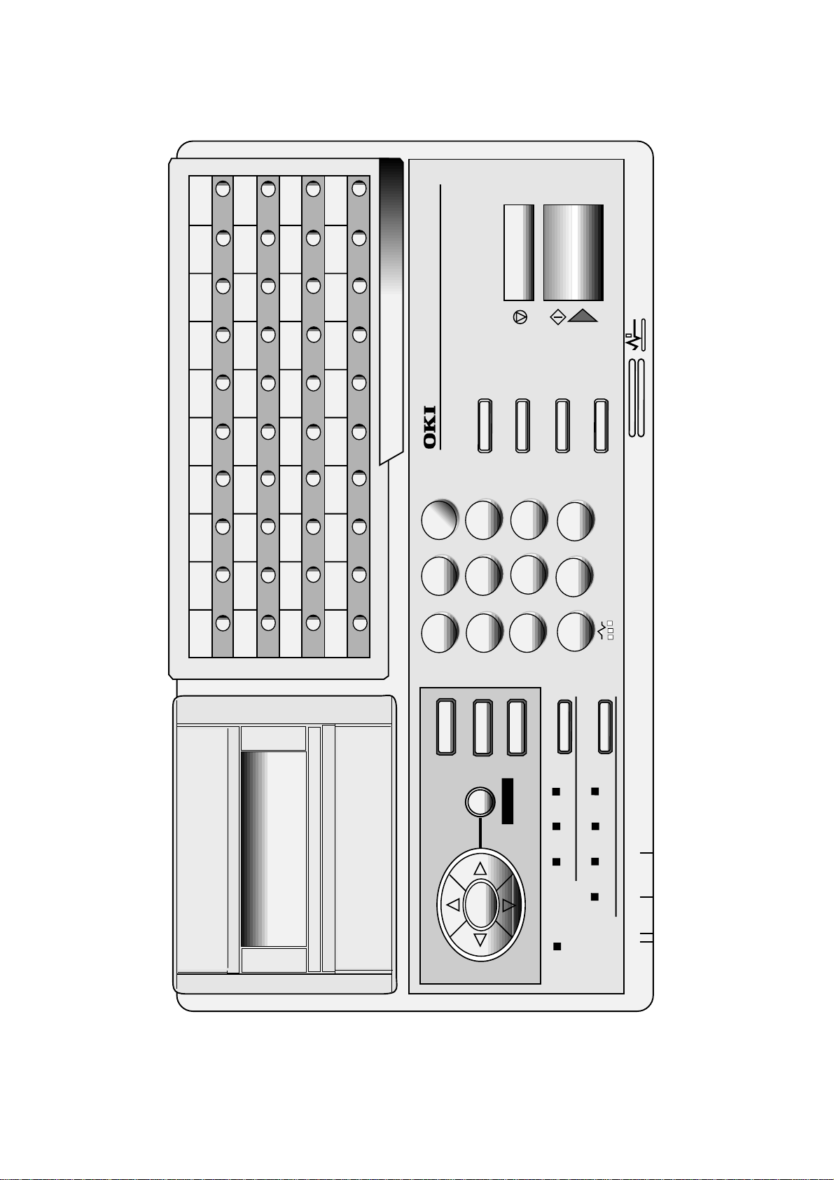
Figure 1.4.1 shows the general appearance of the OKIFAX 5700/5900.
352 mm
Tray-Document
360 mm
472 mm
Stacker-Document
Operation Panel
OKIFAX 5700/5900
Tray-Paper
Figure 1.4.1 General Appearance of OKIFAX 5700/5900
1 - 9
UNIQUE
DEL
PAUSE
5900
OKIFAX
QWERT YUI OP
12345678910
11 12 13 14 15 16 17 18 19 20
ASDFGHJKL
21 22 23 24 25 26 27 28 29 30
ZXCVBNM, ;
31 32 33 34 35 36 37 38 39 40
.\+
SPACE
REDIAL
ABC DEF
@-:/
CAPS
123
HELP
456
MENU/EXIT
HOOK
JKL MNOGHI
CLEAR
STOP
HYPHEN
TUV WXYZPQRS
789
TYPE OF ORIGINAL
COPY
START
SERCH
SPEED DIAL
0#
UNIQUE
*
RESOLUTION
OKIFAX 5700/5900
ENTER
SHIFT
RIGHT
SHIFT UP
SHIFT
LEFT
SHIFT DOWN
Figure 1.4.2 Control Panel of OKIFAX 5700/5900
1 - 10
LIGHTNORMALDARK
ALARM
PHOTO EX FINE FINE STD
8.5" A4 B5 A5

1.5 Basic Performance Specifications
Table 1.5.1 shows basic performance specifications:
Table 1.5.1 Basic Performance Specifications
No. Item Specifications
1 Applicable line
2 Line interface
1) Impedance
2) Sending power level
3) Receiving power level
3 Type of document to be transmit-
ted
1) Width
2) Length
1) PSTN (Public switched telephone network)
2) PBX (Private branch exchange )
3) ISDN (Integrated services digital network): Option
4) LAN (Local area network): Option
600 ohm balanced
Note:
Impedance may differ by the requirement of PTT
0 dBm to -15 dBm range
(Adjustable in 1 dB steps: Technical Setup No.21)
0 dBm to -43 dBm
(In case of V.34 TX/RX, -3 ~ -36 dBm)
Max. 216 mm (NA Letter)
Min. 148 mm (ISO A5)
Note:
Effective reading width is NA Letter (215.4 mm)
Min. 128 mm (5 inch)
Max. 356 mm (14 inch)
Long document detection: 380 mm or 1500 mm
(Technical Setup No. 10: To enables or disables the long
document scanning.)
3) Thickness
4) Shape
5) Opacity
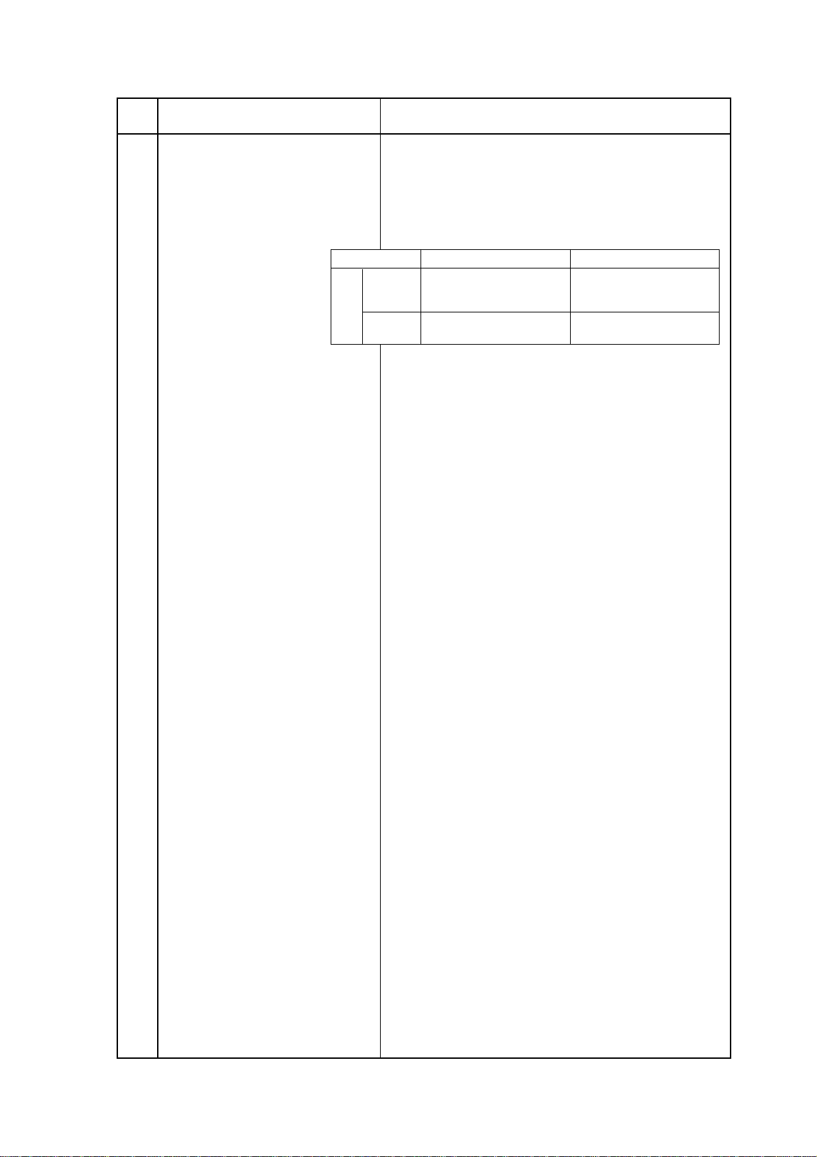
4 Effective reading width
Document Width
NA Letter (216 mm)
US/CANADA
ISO A4 (210 mm)
INT’L
Note (*1):
Printing width will be 206 mm.
Based on common bond paper,
1) 0.08 to 0.13 mm for multiple page feeding
2) 0.06 to 0.15 mm for single page feeding
Rectangular
Document allowing less than 40% of the scanner source
light to pass through them.
Communication
mode/paper width
G3/A4
Copy size
Letter
Effective reading width
215.4 mm for TX
211.3 mm for local copy
G3/A4
A4
208.6 mm for TX
211.3 mm for local copy
(*1)
OKIFAX 5700/5900
1 - 11

No. Item Specifications
5 Automatic document feeder
(ADF) capacity
6 Document skew
7 Document jam detection
8 Document jam removal
9 Document stacking
Max. 50 documents: 20 lb/75gm NA Letter or A4 size
paper
Max. 30 documents: 16 to 28/60 to 105gm NA Letter or A4
size paper
Document shall be placed facedown on ADF stacker.
Max. 1.0 mm skew over any advance of 100 mm.
The occurrence of skew exceeding 1 mm per 100 mm
shall be 0.5% or less.
1) Transmission will stop and a line disconection will
occur when the end of the document is detected
within 380 mm after scanning begins.(except if unlimited: Technical Setup No.10)
2) A jam will also be declared if the document does not
reach the scanning position within about 5 seconds
after the start of a document feed.
Note:
Manual release
Documents up to 297 mm in length, which meet the basic
weight and thickness specification, will exit on the stacker,
and documents of Letter or A4-size will stack in sequence.
The first sheet will be fed first in the feeder and will exit on
the stacker with printing side down.
When a jam is detected during message transmission, the machine will stop, but its receiving capability will remain valid.
10 Recording paper.
For the first or second recording paper cassette:
1) Type: Plain paper (Bond paper: Xerox 4200 type or
equivalent)
2) Size: ISO A4: 210 mm x 297 mm
NA Letter: 215.9 mm x 279.4 mm/8.5 inch x 11 inch
NA Legal 14: 215.9 mm x 355.6 mm/8.5 inch x 14 inch
NA Legal 13: 215.9 mm x 330.2 mm/8.5 inch x 13 inch
3) Weight: 16 lbs to 24 lb/60 to 105gm base weight
Base weight is defind as the weight of 500 sheets of
431.8 mm (17 inch) by 558.8 mm (22 inch) or 1 sheet
of size 1000mm by 1000mm.
4) Thickness: 0.08 mm to 0.13 mm
5) Condition: New paper
For the manual paper feeder:
1) Type: Plain paper, colored paper, printed paper,
envilope
2) Size: LA Letter/A4/NA Legal/Exective/A5/A6/etc.
3) Weight, thickness and condition: Same as above
Note:
For best results use Oki Data recommended papers
1) Xerox 4200 (20-lb/75gm base weight paper)
One single sheet should be loaded on the manual
paper feeder for one occation.
OKIFAX 5700/5900
1 - 12
No. Item Specifications
11 Recording paper cassette
First cassette
Second cassette (option)
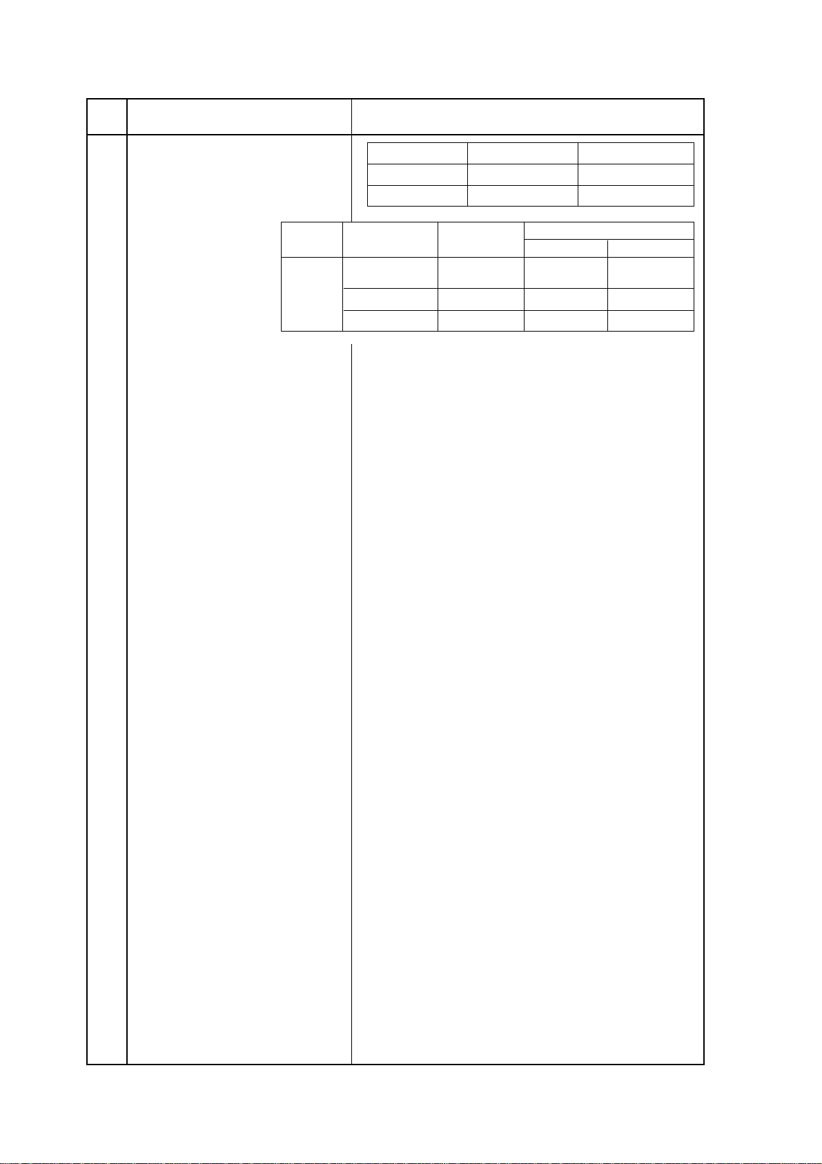
12 Effective recording paper
Up to 250 sheets/cassette
(Oki Data recommended paper)
Up to 500 sheets/cassette
(Oki Data recommended paper)
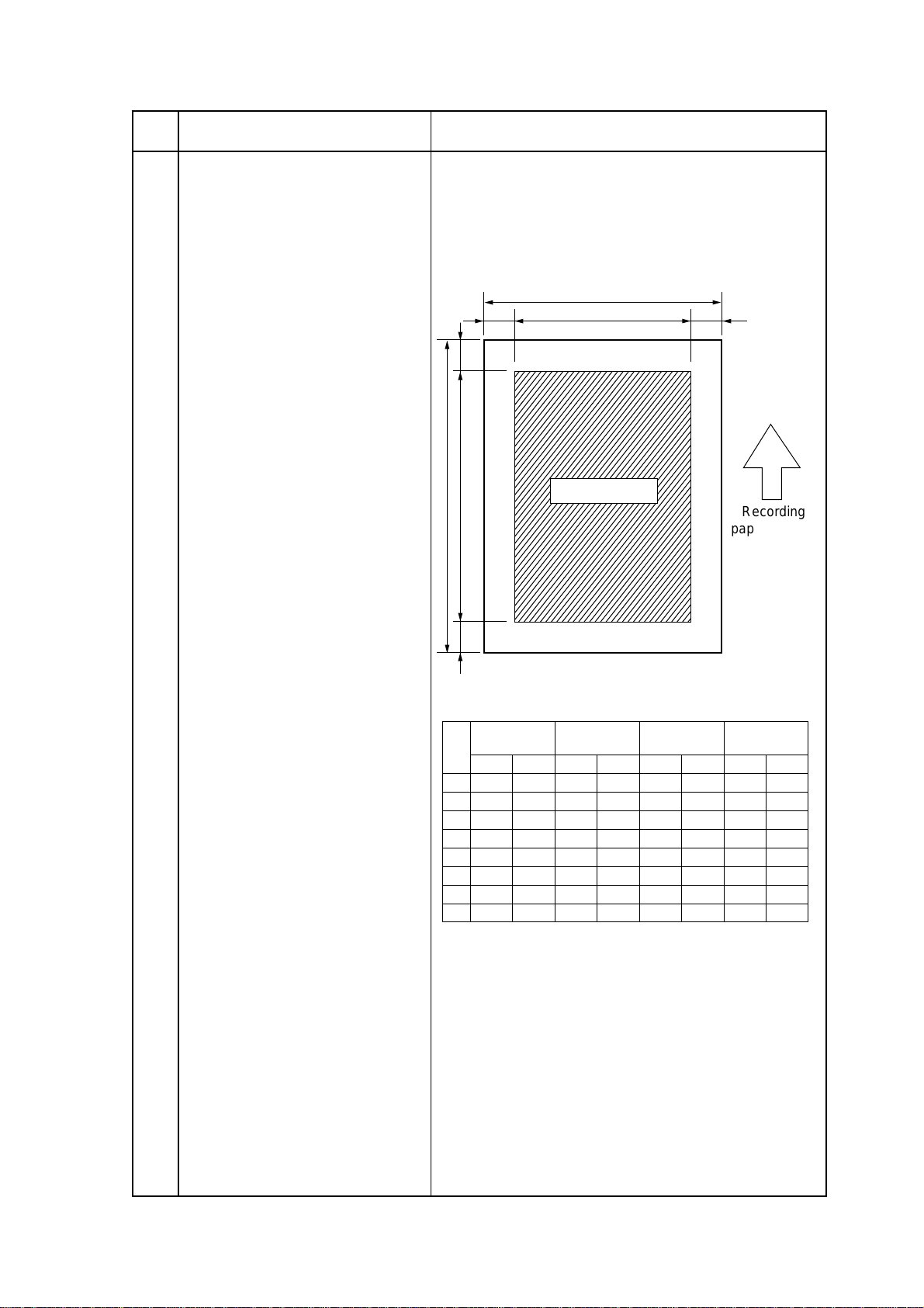
PW
LREW
T
PL
EL
Printing area
Recording
paper feeding
direction
1) Printable area
B
Printable area
Letter Size
A4 Size
inch mm inch mm inch mm inch mm
11PL 279.4 11.7 297 14 355.6 13 330.2
8.5PW 216 8.27 210 8.5 216 8.5 216
10.76EL 273.4 11.46 291 13.76 349.6 12.76 324.2
8.32EW 211.3 8.11 206 8.32 211.3 8.32 211.3
0.12T 3 0.12 3 0.12 3 0.12 3
0.12B 3 0.12 3 0.12 3 0.12 3
0.09L 2.3 0.08 2 0.09 2.3 0.09 2.3
0.09R 2.3 0.08 2 0.09 2.3 0.09 2.3
14 inch
Legal Size
Legal Size
13 inch
`
m
OKIFAX 5700/5900
1 - 13

No. Item Specifications
Letter Size
inch mm inch mm inch mm inch mm
A4 Size
14 inch
Legal Size
13 inch
Legal Size
11PL 279.4 11.7 297 14 355.6 13 330.2
8.5PW 216 8.27 210 8.5 216 8.5 216
10.5EL 266.7 11.2 284.3 13.5 342.9 12.5 317.5
8.0EW 203.2 7.77 197.3 8.0 203.2 8.0 203.2
0.25T 6.35 0.25 6.35 0.25 6.35 0.25 6.35
0.25B 6.35 0.25 6.35 0.25 6.35 0.25 6.35
0.25L 6.35 0.25 6.35 0.25 6.35 0.25 6.35
0.25R 6.35 0.25 6.35 0.25 6.35 0.25 6.35
2) Guaranteed printing area
13 Copy stacking
Guaranteed printing area
Note:
The printable area means the area allowing actual
printing at the time of receiving. The guaranteed
printing area means the area where the printing
quality is guaranteed.
These tables do not include vertical and horizontal
addressing error (+/- 3 mm) of recording paper.
The printed copies will be discharged on the stacker with
printed face up or face down.
1) Face down stacking: Up to 200 copies *
2) Face up stacking: Up to 10 copies *
Note:
1) Using the recommended paper, New standard 20-lb.(Xerox 4200)
2) Except 16 lb papers.
3) Face down or face up stacking is changeable
by the lever.
14 Scanning resolution
15 Scanning method
16 Contrast control
OKIFAX 5700/5900
Horizontal:
• 300 dot/inch
Note:
600 dpi x 15.4 mm; Copy is available.
Vertical:
Transmission mode:
• 300 dot/inch, 15.4 lines/mm (EX-FINE), 7.7 lines/mm
(FINE) or 3.85 lines/mm (STD)
NA Letter size (2592-bits) direct contact image sensor
The Light and Dark contrasts (low contrast) will be auto-
matically enhanced to improve image quality.
Slice level shifting has 3 levels of switch selection on
operation panel.
1 - 14
No. Item Specifications
17 Recording resolution
18 Copy resolution
19 Recording method
20 Recording paper skewing
Horizontal
• 600 dot/inch
Vertical
• 300 dot/inch (EX-FINE), 15.4 line/mm (EX-FINE), 7.7
line/mm (FINE), or 3.85 line/mm (STD)
Variable:
Letter
3.85 ~ 5.28
7.7 ~ 10.57
15.4 ~ 21.15
300 ~ 412
STD
Fine
Ex-Fine (15.4 line/mm)
Ex-Fine (300 dot/inch)
A4
3.85 ~ 4.96
7.7 ~ 9.93
15.4 ~ 19.87
300 ~ 387
• STD: 200 dot/inch x 3.85 line/mm
• FINE/PHOTO: 300 dot/inch x 300 dot/inch
• EX-FINE: 600 dot/inch x 15.4 line/mm
Electro-photographic printing
• 211.3 mm (4992 bits) LED print head
Maximun allowable skew is + or - 1 mm over any advance
of 100 mm.
21 Copy darkness
22 Copy uniformity
23 Recording paper running out
24 Minimum scan line time for
receiving
1) Black image: Greater than 1.2 OD *
2) White background (unprinted area): Not greater than
0.2 OD
Note:
OD: (Optical dencity)
Printed copies will exhibit a uniform density of printed and
background areas:
1) From edge to edge: 25%
2) From copy to the next copy: 30%
The fax can detect the no-paper condition by a
photosensor.
When the paper has run out in the local copy operation,
the scanning will stop with “PAPER JAM” on the LCD and
an ALARM LED turn on without an alarm tone.
When the paper has run out while a message is being
received and the no-paper reception is activated, the LCD
display will show “MSG. IN MEMORY”, and the Alarm
LED turn on.
0 ms, when receiving in ECM mode of from an Oki Data
facsimile.
5 ms at 15.4 line/mm or 7.7 line/mm and 10 ms at 3.85 line/
mm when receiving from a non-Oki Data facsimile or nonECM mode.
OKIFAX 5700/5900
1 - 15
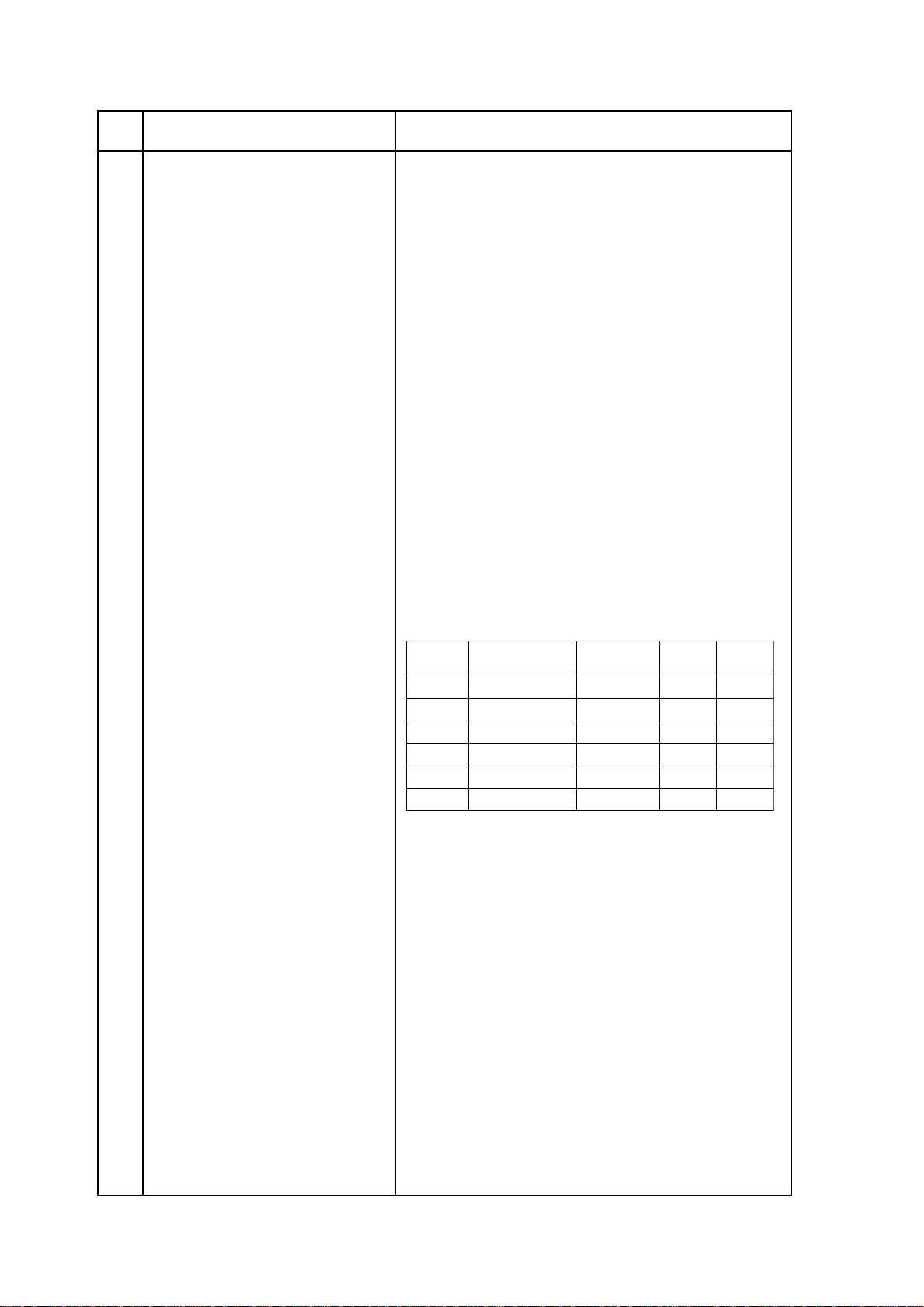
No. Item Specifications
Fall-Back
Rank
Protocol
Transmission
Speed (bps)
No. of
Training
RTN
receivied
1st
ITU-T V.17 (V.33)
14400 1 1
2nd
ITU-T V.17 (V.33)
12000 1 1
3rd
ITU-T V.17 (V.29)
9600 1 1
4th
ITU-T V.17 (V.29)
7200 1 1
5th
ITU-T V.27 ter.
4800 2 1
6th
ITU-T V.27 ter.
2400 2 1
25 Coding scheme
26 Modem operations
27 Fallback
1) One-dimensional coding scheme:
Modified Huffman (MH)
2) Two-dimensional coding scheme:
Modified READ (MR)
Modified Modified READ (MMR)
3) JBIG (only for OKIFAX 5900)
1) High-speed Modem
• ITU-T Rec. V.29 (9600/7200 bps)
• ITU-T Rec. V.27 ter (4800/2400 bps)
• ITU-T Rec. V.17 (14400/12000/9600/7200 bps)
• ITU-T Rec. V.33 (14400/12000 bps)
• ITU-T Rec. V.34 (33600/28800 bps)
2) Low-speed Modem
• ITU-T Rec. V.21 channel 2 (300 bps) or equivalent
3) JBIG:
Performs JBIG communication conforming to T.82/
T.85 of ITU-T Rec.
Note:
Only for OKIFAX 5900, and JBIG is not performed
in G4 communication.
4) ISDN G4:
ITU-T Rec. T.563, T.521, T.503, T.62, T.6, T.70
Automatic fallback will occur according to the following
sequences by FTT, RTN or PPR.
28 Protocol
OKIFAX 5700/5900
When the last trial fails, the transmitting station sends out
a DCN signal to the remote station for disconnection.
Note:
• Modem automatically performs the fall-back depending upon the line condition.
• V.34 fallback sequence:
The modem automatically selects transmission
speed according to the line condition.
1) ITU-T Rec. T.30
2) Oki special protocol (speed protocol)
The T.30 handshaking procedure will be conducted
at message transmission speed instead of 300 baud,
during transmission multi-page.
Note:
In High-speed protocol, V.34 is not applied.
3) ITU-T G4 Class 1 (option)
1 - 16
No. Item Specifications
29 Image transmission time
G3
Basic
30 Error correction scheme (ECM)
31 Communication mode
32 Ringing signal detection sensitiv-
ity
2.5 seconds at 33.6 kbps with JBIG for OKIFAX 5900 and
3.0 seconds at 33.6 kbps for OKIFAX 5700 per sheet of
ITU-T No.1 evaluation test chart.
Note:
This speed denotes the time interval corresponding to Phase C (message transmission phase) as
referred to in ITU-T T.30.
OKIFAX 5700 OKIFAX 5900
Procedure
Time
Image
Time
Note:
Initial
Intermediate
Final
33600 Standard
The above table shows the values under the
8.5 sec. (V34)
1.0 sec. (V34)
1.0 sec. (V34)
Fine
3.0 sec.
4.2 sec.
Initial
Intermediate
Final
33600 Standard
8.5 sec. (V34)
1.0 sec. (V34)
1.0 sec. (V34)
Fine
following conditions:
• Sender ID: OFF
• High-speed protocol: OFF
• Transmission mode: Memory
•Resolution: STD
ITU-T ECM defined in T4, T.30 are provided.
Half-duplex
1) Voltage range
• 25 to 150 V r.m.s.
Inoperative below 10V
Note:
This range may differ by the requirement of PTT.
2.5 sec.
3.5 sec.
2) Frequency range
• 16 to 68 Hz
Note:
This range may differ by the requirement of PTT.
3) Ring response time
• One-ringing signal or 5 sec, 10 sec, 15 sec, and 20
sec selectable
OKIFAX 5700/5900
1 - 17
No. Item Specifications
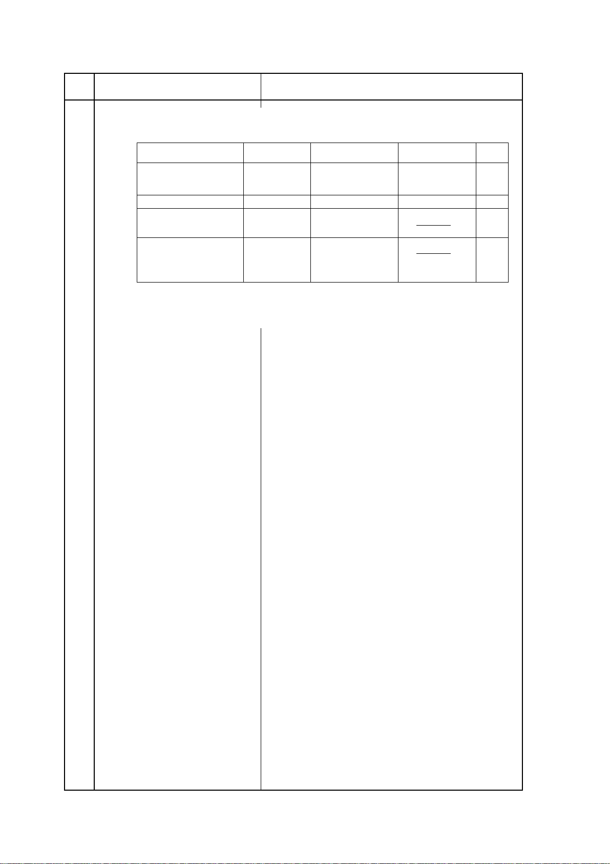
33 Memory capacity (Image
memory)
34 Telephone handset (option)
35 Overheat protection
With
option
board
Basic model Optional memory
2.5 M-byteOKIFAX 5700 2/4 M-byte
4.5 M-byteOKIFAX 5900 2/4 M-byte
Memory
condition
Standard
(without option)
2 M-byte
4 M-byte
Note1:
ITU-T No.1 sample document is used to count the
OKIFAX 5700
[pages]
200
360
520
Print Priority=OFF Print Priority=ON
OKIFAX 5900
360
520
680
340
500
660
number of sheets.
Note2:
Memory back-up time is 72 hours (typical and
Battery full charge condition) after the power off
condition..
General telephone function is available while the power
is on.
Note:
In the fax special versions, general telephone is
available even when the power is off.
The heater of the fuser unit is controlled within the
predetermind temperature range by the thermistor. If the
temperature of the heater exceeds the range, the LCD
displays “PRINTER ALARM4”.
Furethermore, the built-in thermostat in the fuser unit
prevents the heater from being overheated even in the
event of the failures in the above temperature control
circuit.
36 PC interface applications (option)
37 Network print service (option)
The following three modes are supported.
1) PC Printer function
2) PC Scanner function
3) PC FaxModem function
Note1:
Hardware is standard and software is option for
Bi-Centro interface.
Note2:
For details, see appendix “MFP product specification”.
• This function can be used for OKIFAX 5700/5900
network printer service. The OkiHSP NIC (Network
Interface Card) Ethernet Adapter used for OKIFAX
5700/5900 is originally designed for the OkiPage printers and is intended to be forward compatible with
(future) products utilizing an OkiHSP compatible interface.
• Installing the NIC card for OKIFAX 5700/5900 provides
Network print service as an option.
Note:
For details, see appendix “Network Print Service”
OKIFAX 5700/5900
1 - 18
No. Item Specifications
38 ISDN G4 (option)
39 Power supply unit and Power
consumption of the machine
The follwing four modes are supported.
1) G4 function
2) ISDN G4 communication
3) ISDN G3 communication
4) ISDN Report and List
Note:
For details, see appendix “ISDN G4 option system specifications”.
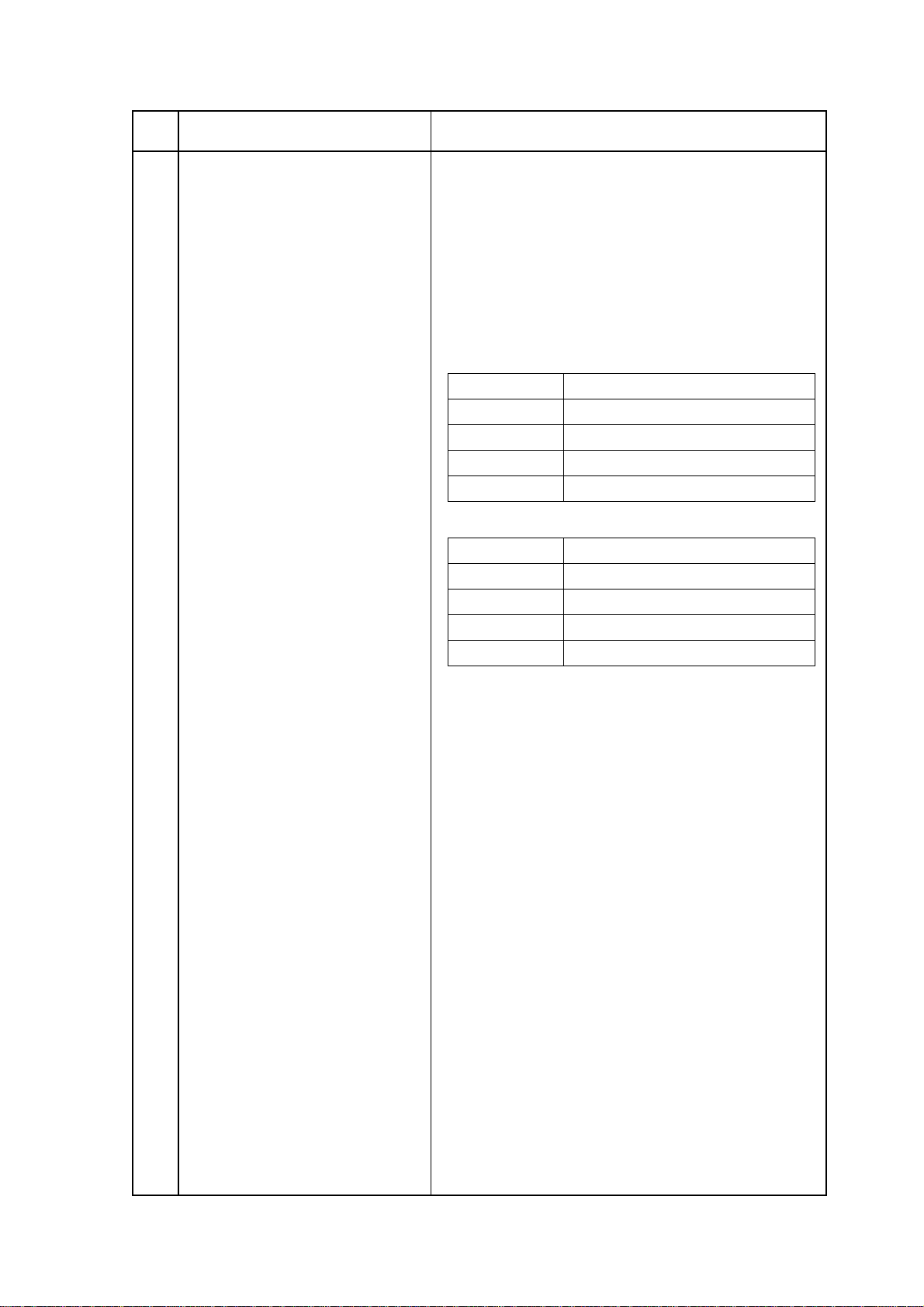
Power consumption of the machine (Typical power with-
out optional board)
1) US/CANADA version
Mode Typical power (W)
Transmit 28 W
Receive 355 W
Local copy
Standby
360 W
12 W
2) INT’L version
Mode Typical power (W)
Transmit
Receive
Local copy
Standby
28 W
355 W
360 W
12 W
(0.5 W)
Note:
( ): When power save mode is set to ON.
Chart: ITU-T No.1
OKIFAX 5700/5900
1 - 19
No. Item Specifications
40 Ambient condition
Temperature and Humidity
Temperature
Humidity
Maximum wet bulb
temperature
Minimum difference
between wet and dry
bulb temperatures
1. Storage conditions specified above apply to the machine in packed condition.
2. Temperature and humidity must be in the range where no condensation occurs.
41 Dimension (Main body)
42 Weight (Main body)
43 Attachment (to the main body)
In operation
50 - 90
(10 - 32)
20 - 80
77
(25)
35.6
(2)
1) Width: Approx. 360 mm
2) Depth: Approx. 472 mm
3) Height: Approx. 352 mm
Approx. 14 kg
Excluding recording paper and packing materials.
1) AC power cord x 1
2) I/D unit x 1 (Already installed)
3) Toner cartrige x 1
4) Telephone line cord x 1
5) Document stacker x 1
6) One touch sheet x 1 (Already installed)
7) User’s guide x 1
Power off mode
32 - 110
(0 - 43)
10 - 90
80.4
(26.8)
35.6
(2)
During Storage
14 - 110
(-10 - 43)
10 -90
Unit
°F
(°C)
%RH
°F
(°C)
°F
(°C)
OKIFAX 5700/5900
1 - 20

1.6 Reports and Lists
Table 1.6.1 shows Report and Lists Specifications.
Table 1.6.1 Report and Lists Specifications
No. Item Specifications
1 Active memory files
2 Activity report
3 Message confirmation report
This report will be manually or automatically printed out
for information of transmission/reception data stored in
the memory. When there is no stored image data in the
memory at all, the Active memory files is not printed out.
(MENU key ∅ Report Print)
See Fig. 1-6-1-1 to Fig. 1-6-1-3
The fax can print out an activity report manually, and
provides of fax machine’s last 30 communications. The
report does not contain the results of messages which
were received without errors. However, it does contain
messages received in memory with or without errors.
(MENU key ∅ Report Print)
See Fig. 1-6-2
This report will be manually or automatically printed out
after completion of memory transmission.
1) Manual print
By pressing the ENTER key after a communication.
2) Automatic printout
When the Report Options (to enable or disable automatic printing after a communication) is set to Enable.
• Single location: (MENU key ∅ SETUP ∅ Report
Options: No.70)
• Multi location: (MENU key ∅ SETUP ∅ Report
Options: No.71)
See Fig. 1-6-3-1 and Fig. 1-6-3-2
4 Broadcast entry report
5 Broadcast confirmation report
6 Configuration report
7 Telephone directory
OKIFAX 5700/5900
This report will be manually printed out if specified during
operating sequence of a broadcast.
See Fig. 1-6-4-1 and Fig. 1-6-4-5
This report will be manually or automatically printed out
the broadcast confirmation report.
(MENU key ∅ Report Print)
See Fig. 1-6-5-1 to Fig. 1-6-5-5
This report will be manually printed out for maintenance
purpose.
(MENU key ∅ Report Print)
See Fig. 1-6-6-1 to Fig. 1-6-6-5
This report will be manually printed out and print destinations registered only.
(MENU key ∅ Report Print)
See Fig. 1-6-7-1 to Fig. 1-6-7-14
1 - 21

No. Item Specifications
8 Power outage report
9 Confidential reception report
10 Protocol dump (G3)
11 Self-diagnosis report
If received communications are lost due to power failure,
this report is printed out automatically at power recovery.
The information printed on the Power outage report is not
printed out on the Activity report.
See Fig. 1-6-8
This report will be informed operator about a stored
confidential messages in the memory and automatically
printed out.
See Fig. 1-6-9
This report will be manually printed out for maintenance
purpose.
If the previous communication is G3, G3 communication
protocol dump is printed out.
(MEMU key ∅ Report Print)
See Fig. 1-6-10-1 and Fig. 1-6-10-2
This report will be manually printed out for maintenance
purpose.
(To check ROMs, RAMs and Printing function.)
(MENU key ∅ RESOLUTION key twice ∅ Technical
PRG ∅ Local Test ∅ Self-diagnosis)
See Fig. 1-6-11-1 and Fig. 1-6-11-2
12 Log report
13 Function list
14 Group directory
15 Protocol dump (G4)
This report will be manually printed out for fault analysis.
(MENU key ∅ Report Print)
See Fig. 1-6-12
This list can be printed out manually from the report
operation.
This list is printed out user function only and does not print
technical function.
(MENU key ∅ Report Print)
See Fig. 1-6-13-1 to Fig. 1-6-13-6
This list can be printed out manually for a selected group
only (Group #1 to #20) through operation. This list cannot
output all group at a time.
If Group is omitted, report will not be printed out.
(MENU: No.8 ∅ Report Print: No.4)
See Fig.1-6-14-1 to Fig. 1-6-14-4
This report will be manually printed out for maintenance
purpose.
If it is G4, the G4 communication protocol dump is printed
out.
(MENU: No.8 ∅ Report Print: No.8)
See Fig. 1-6-15-1 and Fig. 1-6-15-2
16 NIC (Network Interface Card)
configuration
OKIFAX 5700/5900
This report will be manually printed out for maintenance
purpose.
(MENU: No.8 ∅ Report Print: No.9)
See Fig. 1-6-16-1 and Fig. 1-6-16-2
This report is not available for localization.
1 - 22

ACTIVE MEMORY FILES P1
12/24/1998 19:10
RECEPTION
ENTRIES PAGES
05 020
TRANSMISSION
DATE TIME DISTANT STATION ID MODE PAGES
12/24 13:00 OKI DATA SYS-1 CALLING 003
12/24 12:03 OKI DATA SYS-2 CALLING 001
12/24 13:00 OKI DATA SYS-3 CALLING 002
12/24 13:05 OKI DATA SYS-4 CALLING 002
12/24 14:00 OKI DATA SYS-5 CALLING 002
12/24 14:30 OKI DATA SYS-6 CALLING 002
12/24 15:10 OKI DATA SYS-7 CALLING 002
12/24 15:15 OKI DATA SYS-8 CALLING 002
12/24 15:30 OKI DATA SYS-9 CALLING 002
12/24 15:50 OKI DATA SYS-10 CALLING 002
12/24 16:10 OKI DATA SYS-11 CALLING 002
12/24 16:30 OKI DATA SYS-12 CALLING 002
12/24 16:50 OKI DATA SYS-13 CALLING 002
12/24 17:00 OKI DATA SYS-14 CALLING 002
12/24 17:10 OKI DATA SYS-15 CALLING 002
12/24 17:30 OKI DATA SYS-16 CALLING 002
12/24 17:42 OKI DATA SYS-17 CALLING 002
12/24 17:50 OKI DATA SYS-18 CALLING 002
12/24 17:59 OKI DATA SYS-19 CALLING 002
12/24 18:00 OKI DATA SYS-20 CALLING 002
12/24 18:10 OKI DATA SYS-21 CALLING 002
12/24 18:20 OKI DATA SYS-22 CALLING 002
12/24 18:20 OKI DATA SYS-23 CALLING 002
12/24 18:20 OKI DATA SYS-24 CALLING 002
12/24 18:30 OKI DATA SYS-25 CALLING 002
12/24 18:32 OKI DATA SYS-26 CALLING 002
12/24 18:35 OKI DATA SYS-27 CALLING 002
12/24 18:40 OKI DATA SYS-28 CALLING 002
12/24 18:42 OKI DATA SYS-29 CALLING 002
12/24 18:45 OKI DATA SYS-30 CALLING 002
12/24 18:50 OKI DATA SYS-31 CALLING 002
12/24 18:52 OKI DATA SYS-32 CALLING 002
12/24 18:53 OKI DATA SYS-33 CALLING 002
12/24 18:55 OKI DATA SYS-34 CALLING 002
12/24 18:57 OKI DATA SYS-35 CALLING 002
12/24 18:59 OKI DATA SYS-36 CALLING 002
12/24 19:00 OKI DATA SYS-37 CALLING 002
12/24 19:00 OKI DATA SYS-38 CALLING 002
ID=ODS
POLLING TX/RX
DATE TIME DISTANT STATION ID MODE PAGES
12/24 12:05 123456789012345678901234POLLING
POLLED 0 0 3
Fig. 1-6-1-1 Active Memory Files P1 (In case of more than 1 page)
OKIFAX 5700/5900
1 - 23

ACTIVE MEMORY FILES P2
PERSONAL BOX
BOX NO. MODE ENTRIES PAGES
0 1 CONF 0 3 0 2 0
0 2 CONF 0 1 0 0 2
0 3 CONF 0 1 0 0 5
0 4 CONF 0 1 0 0 5
05 POLL 01 005
06 POLL 01 005
07 POLL 01 005
08 POLL 01 005
09 POLL 01 005
10 POLL 01 005
11 POLL 01 005
12 POLL 01 005
13 POLL 01 005
14 POLL 01 005
15 POLL 01 005
16 POLL 01 005
12/24/1998 19:10
ID=ODS
Fig. 1-6-1-2 Active Memory Files P2 (In case of more than 1 page)
OKIFAX 5700/5900
1 - 24
 Loading...