

Page 1

User Guide:
RS-232C/RS-422 Serial
Interface Option
for OKI® B6100 Printer
59345001
Page 2

i RS-232C/RS-422 Serial Interface Option
Trademarks
The following are trademarks or registered trademarks of their respective owners. Other product names mentioned in
this manual may also be trademarks or registered trademarks of their respective owners. Registered trademarks are
registered in the United States Patent and Trademark Office; some trademarks may also be registered in other
countries. PostScript is a trademark of Adobe Systems Incorporated for a page description language and may be
registered in certain jurisdictions.
OKI, OkiLPR, and OkiLAN are registered trademaks of Oki Electric Industry Company, Ltd.
Adobe, Adobe PhotoShop, Adobe PageMaker/Adobe Systems Incorporated
OpenVMS, Compaq/Compaq Computer Corporation
Microsoft, MS-DOS, Windows/Microsoft Corporation
The ENERGY STAR logo/United States Environmental Protection Agency. The ENERGY STAR emblem does not
represent EPA endorsement of any product or service.
Proprietary Statement
The digitally encoded software included with your printer is copyrighted. All Rights Reserved. This software may
not be reproduced, modified, displayed, transferred, or copied in any form or in any manner or on any media, in
whole or in part, without the express written permission of the manufacturer.
Copyright Notice
This manual is copyrighted. All Rights Reserved. This manual may not be copied in whole or in part, nor transferred
to any other media or language, without the express written permission of the manufacturer.
The specifications of your printer and the content of this publication are subject to change without prior notice.
Every attempt has been made to verify the accuracy of the content herein
Page 3

How This Guide is Organized
Chapter 1 - In stalling the Serial Interface
This chapter explains the procedure for installing the RS-232C/RS-422 Serial Interface op tion
in OKI B6100 Laser Printers.
Chapter 2 - Using the RS232-C/RS422 Serial Interface
This chapter lists the Serial Interface setup features and available selections via the control
panel menus. The Serial Interface connector pinouts are listed. Troubleshooting error messages appearing on the printer’s control panel are also discussed.
Chapter 3 - Troubleshooting
This chapter discusses troubleshooting error messages appearing on the printer’s control
panel. Sources of help, information and technical support are also discussed.
Features of the RS-232C/RS-422 Serial Interface
The RS-232C/RS-422 Serial Interface for your printer provides the following:
RS-232C/RS-422 Serial Interface Option ii
• RS-232C or RS-422 support
• Baud rate support from 1200 bps to 115200 bps
• DB-25 female connector
• Quick and easy installation requiring no tools
• Control panel menus enable fast and easy configuration and trou bleshooting.
Printer Requirements
Before installing the RS-232C/RS-422 Serial Interface option, you will need to make sure of the following two requirements:
• Make sure that your printer has a free network port access slot.
• Make sure that your printer’s “Product Version” is V2.03a or later. If you are unsure of your
printer’s version of code, print a Configuration Summary as described in the user’s guide that came
with your printer. If your printer has an earlier version of code contact your point of purchase.
Page 4
iii RS-232C/RS-422 Serial Interface Option
Safety Precautions
Safety Precautions
CAUTION: Handling ESD-Sensitive Parts
Many electronic parts use parts that are known to be sensitive to electrostatic discharge (ESD). To
prevent damage to ESD-sensitive parts, follow the instructions below in addition to all the usual
precautions, such as turning off power before removing logic boards:
• Keep the ESD-sensitive part in its original shipping cont ainer (a special “ESD bag”) until you are
ready to install the part into the machine.
• Make the least-possible mov eme nts wit h you r body to prevent an i ncrease o f st atic el ectrici ty from
clothing fibers, carpets, and furniture.
• Use an ESD wrist strap on your wrist if available. Connect the wrist band to the system ground
point. This discharges any static electricity in your body to the machine.
• Hold the ESD-sensitiv e part by its edge co nn ector cover ; do no t touc h its pins. I f you are r emovi ng
a pluggable modu le, use the correct tool.
• Do not place the ESD-sens itive pa rt on any met al surface; i f you nee d to pu t down t he ESD-se nsi-
tive part for any reason, first put it into its special bag.
• Metal surfaces are electrical grounds. They increas e the risk of damage because they make a di s-
charge path from your bo dy throug h th e ES D-sens itiv e par t. (La r g e met al objects can be disc harged
paths without being grounded.)
• Prevent ESD-sensiti ve parts from being accidentally touched by other personnel.
• Take ext ra care working with ESD-sensitiv e parts when cold weather hea ting is used becaus e low
humidity increases static electricity.
WARNING: To prevent the danger of electric shock, before installing any options be sure to
turn the power switch of the printer to the off [O] position and disconnect the power cord from
the wall outlet.
Page 5

Contents
How This Guide is Organized iii
Features of the RS-232C/RS-422 Serial Interface iii
Printer Requirements iii
Safety Precautions iv
Chapter 1 Installing the Serial Interface in
OKI B6100 Printers1-1
About this Chapter 1-2
Installing the RS-232C/RS-422 Serial Interface in
OKI B6100 Printers 1-2
Chapter 2 Using the RS-232C/RS-422
Serial Interface 2-1
About this Chapter 2-2
Control Panel MENU structure 2-2
SERIAL SETUP Menu 2-4
Interpreter 2-4
Format 2-4
Page 6

vi RS-232C/RS-422 Serial Interface Option
Serial Mode 2-4
Baud Rate 2-4
Data Bits 2-4
Stop Bits 2-4
Parity 2-5
DTR Ready/Busy 2-5
DTR Onl/Offl 2-5
DTR Error 2-5
RTS Ready/Busy 2-5
RTS Onl/Offl 2-5
RTS Error 2-5
XON Ready/Busy 2-5
XON Onl/Offl 2-6
XON Error 2-6
DTR Polarity 2-6
RTS Polarity 2-6
Robust XON 2-6
Disabling the Serial Interface 2-6
Serial 2-6
References for OpenVMS users 2-7
RS-232C Serial Cable Pin Assignments 2-7
RS-422 Serial Cable Pin Assignments 2-7
Chapter 3 Troubleshooting 3-1
About this Chapter 3-2
Control Panel Error Messages 3-2
Example 3-2
Obtaining Help and Information 3-2
Your Po in t of Pu r ch a se 3 -3
Your Application Vendor 3-3
Technical Support 3-3
Page 7

Chapter 1
Installing the Serial Interface in
OKI B6100 Printers
In this Chapter. . .
• “About this Chapter” on page 1-2
• “Installing the RS-232C/RS-422 Serial Interface in OKI B6100 Printers” on page
1-2
Page 8
1-2 RS-232C/RS-422 Serial Interface Option
Installing the RS-232C/RS-422 Serial Interfa ce i n OKI B6100 Printers
About this Chapter
This chapter explains the procedure for installing the RS-232C/RS-422 Serial Interface option in OKI
B6100 Printers.
Installing the RS-232C/RS-422 Serial Interface in OKI B6100 Printers
1. Carefully review the safety precautions in the front of this guide before starting this installation
procedure.
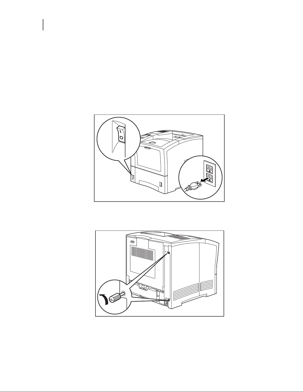
2. Ensure that the printer power switch is set to the OFF [ O ] position and unplug the power cord
from the AC outlet.
3. Loosen the thumbscrews at the top and bottom of the left side cover by turning them in a
counter-clockwise direction.
Page 9

RS-232C/RS-422 Serial Interface Option 1-3
4. Slide the cover towards the rear of the printer and then downwards to remove it.
5. Turning thumbscrews counter-clockwise, remove the blank metal plate covering one of the avail-
able network ports on the controller bracket.
NOTE: It is not necessary to remove the controller from your printer to install the serial interface. For
clarity, the following illustrations depict a controller removed from the printer. When facing the
front of the control ler as shown below, network port 1 is on the right and networ k port 2 is on the
left. However , when insta lled in th e printe r , n etwork po rt 1 is on the b ottom and networ k port 2 is o n
top. In the following few steps, a serial network interface is being installed in network port 2.
Page 10

1-4 RS-232C/RS-422 Serial Interface Option
Installing the RS-232C/RS-422 Serial Interfa ce i n OKI B6100 Printers
6. While aligning the front bracket of the serial interface assembly to the two res pective thum bscrews
on the controller assembly bracket, firmly seat the 80-pin male connector on the underside of the
interface to the 80-pin female connector on the controller assembly.
7. Secure the serial interface assembly to the controller bracket by tightening the two smaller thumb-
screws in a clockwise direction.
Page 11

RS-232C/RS-422 Serial Interface Option 1-5
8. Insert the top part of the left side cover into the printer. Ensure the locking tab aligns with the hole
in the printer’s side.
9. Slide the side cover towards the front of the printer to install it.
10. Tighten both thiumbscrews in a clockwise direction.
Page 12

1-6 RS-232C/RS-422 Serial Interface Option
Installing the RS-232C/RS-422 Serial Interfa ce i n OKI B6100 Printers
11. Connect the power cord to the wall outlet and turn the printer power switch to the ON [ I ] position.
The installation of your RS-232C/RS-422 serial interface option in your OKI B6100 printer is now complete. Proceed to Chapter 2 Using the RS-232C/RS-422 Serial Interface.
• • •
Page 13

Chapter 2
Using the RS-232C/RS-422
Serial Interface
In this Chapter. . .
• “About this Chapter” on page 2-2
• “Control Panel MENU structure” on page 2-2
• “SERIAL SETUP Menu” on page 2-4
• “Disabling the Serial Interface” on page 2-6
• “References for OpenVMS users” on page 2-7
• “RS-232C Serial Cable Pin Assignments” on page 2-7
• “RS-422 Serial Cable Pin Assignments” on page 2-7
Page 14

2-2 RS-232C/RS-422 Serial Interface Option
Control Panel MENU structure
About this Chapter
This chapter lists the Serial Interface setup features and available selections via the control panel menus.
The Serial Interface connector pinouts are listed. Troubleshooting error messages appearing on the
printer ’s control pane l are also discussed.
Control Panel MENU structure
When the RS-232C/RS-422 serial interface is installed, the printer control panel menu structure is
enhanced as shown in the following table. The shaded areas denote additional features and settings relevant to the RS-232C/RS-422 interface.
Menu
Paper Menu
Interface Menu
Port
Parallel
Serial
Parallel Setup
Serial Setup Off
Interpreter
Format
Serial Mode
Baud Rate
Data Bits
Stop Bits
Parity
On
Auto Switch
PCL
Postscript 3
Normal
Binary
Raw
RS232
RS422
1200
2400
4800
9600
19200
38400
57600
115200
7
8
1
2
Page 15

PS Menu
PCL Menu
System Menu
RS-232C/RS-422 Serial Interface Option 2-3
None
Even
Odd
DTR Ready/Busy
On
Off
DTR Onl/Offl
On
Off
DTR Error
On
Off
RTS Ready/Busy
On
Off
RTS Onl/Offl
On
Off
RTS Error
On
Off
XON Ready/Busy
On
Off
XON Onl/Offl
On
Off
XON Error
On
Off
DTR Polarity
High
Low
RTS Polarity
High
Low
Robust XON
On
Off
NOTE: The structu re of your display menus may vary slight ly depending on th e options installed in your
printer.
Page 16

2-4 RS-232C/RS-422 Serial Interface Option
SERIAL SETUP Menu
SERIAL SETUP Menu
The following selections becomes available within a SERIAL SETUP submenu of the INTERFACE
menu when the RS-232C/RS-422 serial interface is installed.
Interpreter
AVAILABLE SELECTIONS Auto Switch
DEF AULT Auto Switch
Format
AVAILABLE SELECTIONS Normal
DEFAULT Raw
Serial Mode
PCL
Postscript 3
Binary
Raw
Baud Rate
Data Bits
Stop Bits
AVAILABLE SELECTIONS RS232
RS422
DEFAULT RS232
AVAILABLE SELECTIONS 1200
2400
4800
9600
19200
38400
57600
115200
DEF AULT 9600
AVAILABLE SELECTIONS 7
8
DEF AULT 8
AVAILABLE SELECTIONS 1
DEF AULT 1
2
Page 17

Parity
AVAILABLE SELECTIONS None
DEFAULT None
DTR Ready/Busy
AVAILABLE SELECTIONS Off
DEF AULT Off
DTR Onl/Offl
AVAILABLE SELECTIONS Off
DEF AULT Off
DTR Error
RS-232C/RS-422 Serial Interface Option 2-5
Parity
Even
Odd
On
On
AVAILABLE SELECTIONS Off
DEF AULT Off
RTS Ready/Busy
AVAILABLE SELECTIONS Off
DEF AULT Off
RTS Onl/Offl
AVAILABLE SELECTIONS Off
DEF AULT Off
RTS Error
AVAILABLE SELECTIONS Off
DEF AULT Off
XON Ready/Busy
On
On
On
On
AVAILABLE SELECTIONS Off
On
DEF AULT Off
Page 18

2-6 RS-232C/RS-422 Serial Interface Option
Disabling the Serial Interface
XON Onl/Offl
AVAILABLE SELECTIONS Off
DEF AULT Off
XON Error
AVAILABLE SELECTIONS Off
DEF AULT Off
DTR Polarity
AVAILABLE SELECTIONS High
DEF AULT High
RTS Polarity
AVAILABLE SELECTIONS High
DEF AULT High
On
On
Low
Low
Robust XON
AVAILABLE SELECTIONS Off
DEF AULT Off
Disabling the Serial Interface
The following selection becomes available within the PORT submenu of the INTERFACE menu when
the RS-232C/RS-422 serial interface is installed.
Serial
The Serial option enables you to turn off the serial port on the interface. This selections is often used to
permit uninterrupted communication to other ports such as the parall el or other net work ports.
AVAILABLE SELECTIONS On
DEF AULT On
On
Off
Page 19

References for OpenVMS users
You can print to your laser printer via the serial interface option from an OpenVMS system, either
directly connected to the system or through a network device such as a terminal server.
It is recommended that DECprint Supervisor (DCPS) be used for printing. Please see the "Setting Up
Printers" chapter of the DCPS Sys t em Manager’s manua l for informat ion on cr eating a DCPS print
queue.
If DCPS will not be used, please see the "Setting Up and Maintaining Queues" chapter of the OpenVMS
System Manager’s manual for information on setting up print queues using th e O penVMS print symbiont.
RS-232C Serial Cable Pin Assignments
Eight pins of the 25-pin serial cable are utilized for the RS-232C standard:
Pin No. Signal Direction Description
RS-232C/RS-422 Serial Interface Option 2-7
Serial
1 GND Frame Ground
2 TXD Out Transmit Data
3 RXD In Receive Data
4 RTS Request To Send
5 CTS In Clear To Send
6 DSR In Data Set Rea dy
7 GND Logic Ground
20 DTR Out Data Te rminal Ready
RS-422 Serial Cable Pin Assignments
Five pins of the 25-pin serial cable are utilized for the RS-422 standard:
Pin No. Signal Direction Description
1 GND Frame Ground
15 RXD - In Receive Data +
17 RXD + In Receive Data -
19 TXD - Out Transmit Data -
25 TXD + Out Transmit Data +
• • •
Page 20

2-8 RS-232C/RS-422 Serial Interface Option
RS-422 Serial Cable Pin Assignment s
Page 21

Chapter 3
Troubleshooting
In this Chapter. . .
• “About this Chapter” on page 3-2
• “Control Panel Error Messages” on page 3-2
• “Obtaining Help and Information” on page 3-2
• “Technical Support” on page 3-3
Page 22

3-2 RS-232C/RS-422 Serial Interface Option
Control Panel Error Messages
About this Chapter
This chapter di scusses troubleshooting error messages appearing on the printer’s control panel. Sources
of help, information and technical support are also discussed.
Control Panel Error Messages
The format of control panel error messages is:
where x indicates the network slot where the serial interface is installed
and
where y reflects the error number as shown below:
Error No. Description Action Required
1 Overrrun Error Verify that all DTS, RTS and XON settings within
NETx: ERROR y
the SERIAL SETUP menu are configured correctly.
Check the pinout assignments of cabling between
the printer and the host.
2 Parity Error Verify that the PARITY setting within the SERIAL
3 Framing Error Verify that the SERIAL MODE, BAUD RATE,
4 Flow Control Error Verify that all DTS, RTS and XON settings within
Example
An error message of:
NET2: ERROR3
indicates that the serial interface which is located in network slot 2 has experienced a framing error.
Obtaining Help and Information
Several sources of help and information are available, depending on the type of help you need:
SETUP menu is configured correctly.
Check the pinout assignments of cabling between
the printer and the host.
DATA BITS, STOP BITS and PARITY settings
within the SERIAL SETUP menu are configured
correctly.
the SERIAL SETUP menu are configured correctly.
Check the pinout assignments of cabling between
the printer and the host.
Page 23

Your Point of Purchase
Your local vendor fro m w ho m y ou pu rchas e d t his pr in t er m a y b e best equipped to help you. Yo ur ven dor
has specially trained service technicians available to answer questions an d the equip ment to analyze your
printer problems.
Your Application Vendor
Often, “printing” problems have more to do with the application being used than with the printer. In this
case, the application manufacture is the best source of help.
OKI Resou rces
Available 24/7 (24 Hours a Day, 7 Days a Week)
• Visit our multilingual web site www.okidata.com
• Visit http://my.okidata.com
• Call 1-800-654-3282
Technical Support
RS-232C/RS-422 Serial Interface Option 3-3
Your Point of Purchase
T ech nical Supp ort is av ailable wor ld-wide. Pleas e re fer t o yo ur poi n t of purchase for the appropriate contact in your area.
When calling for assistance, please have the following information readily available:
• Your ph one number, fax number and shipping address.
• A descript ion of the problem.
• The printer model.
• The type of host computer you are using.
• The type and version of operating system you are using.
• The application and ve rsion you are using.
• The interface you are using (e.g., network, parallel, serial).
• If using the network interface, the network protocol (TCP/IP, EtherTalk, IPX/SPX, NetBIOS/NetBEUI).
• The printer emulation you are using (e.g., PCL or PostScript).
• A printout of your printer’s Configuration Summary. (Refer to your printer’s User manual).
• If you have a printer hardware pr oblem you can not res olve, prov ide the error mes sage dis played on
the Control Panel. For a list of error messages, refer to your printer’s User manual.
NOTE: To confirm that a problem is isolated to the RS-232C/RS-422 Serial Interface, you may want to
remove the serial interface from the printer and diagnose the pri nter using the User ’s Manual that
came with your printer. If the condition persists, it can be assumed that the problem resides within
the printer and not necessarily the serial interface.
• • •
Page 24

3-4 RS-232C/RS-422 Serial Interface Option
T echnical Support
 Loading...