


PT390
Every effort has been made to ensure that the information in this document is complete, accurate, and
up-to-date. The manufacturer assumes no responsibility for the results of errors beyond its control. The
manufacturer also cannot guarantee that changes in software and equipment made by other
manufacturers and referred to in this manual will not affect the applicability of the information in it.
Mention of software products manufactured by other companies does not necessarily constitute
endorsement by the manufacturer.
While all reasonable efforts have been made to make this document as accurate and helpful as possible,
we make no warranty of any kind, expressed or implied, as to the accuracy or completeness of the
information contained herein.
All rights are reserved by Oki Data Corporation. Unauthorized copying, transferring, translating, or
related actions are prohibited. You must obtain written permission from Oki Data Corporation before
doing any of the above.
© 2011 Oki
OKI is a registered trademark of Oki Electric Industry Co., Ltd.
Energy Star is a trademark of the United States Environmental Protection Agency.
Microsoft, Windows, Windows Server and Windows Vista are registered trademarks of Microsoft
Corporation.
Apple, Macintosh, Rosetta, Mac and Mac OS are registered trademarks of Apple Inc.
Other product names and brand names are registered trademarks or trademarks of their proprietors.
Data Corporation
As an Energy Star Program Participant, the manufacturer has determined that this product
meets the Energy Star guidelines for energy efficiency.
This product complies with the requirements of the Council Directives 2014/30/EU (EMC) and
2014/35/EU (LVD), 2014/53/EU (RED) and 2011/65/EU(RoHS) as amended where
applicable, on the approximation of the laws of the member states relating to Electromagnetic
Compatibility, Low Voltage, Radio & Telecommunications Terminal Equipment, Energy
related Products and Restriction on the use of certain Hazardous Substances in electrical
and electronic equipment.
The following cables were used to evaluate this product to achieve EMC directive
2014/30/EU compliance and configurations other than this may affect that compliance.
&$%/(7<3( &25(CORE
CABLE TYPE
Power 2.0
USB 5.0
Serial (25pin)
Parallel 2.9
LAN
Drawer 1.8
This is a class A product as defined in EN55022. In a domestic environment
this product may cause radio interference, in which case the user may be required to
take adequate measures.
LENGTH
(METRE)
15.0
10.0
CORE SHIELD
88
89
89
89
88
88

M
ANUFACTURER
Oki Data Corporation,
4-11-22 Shibaura, Minato-ku,
Tokyo 108-8551,
Japan
For all sales, support and general enquiries contact your local distributor.
I
MPORTER TO THE
OKI Europe Limited (trading as OKI Printing Solutions)
Blays House
Wick Road
Egham
Surrey, TW20 0HJ
United Kingdom
For all sales, support and general enquiries contact your local distributor.
E
NVIRONMENTAL INFORMATION
EU/A
UTHORISED REPRESENTATIVE
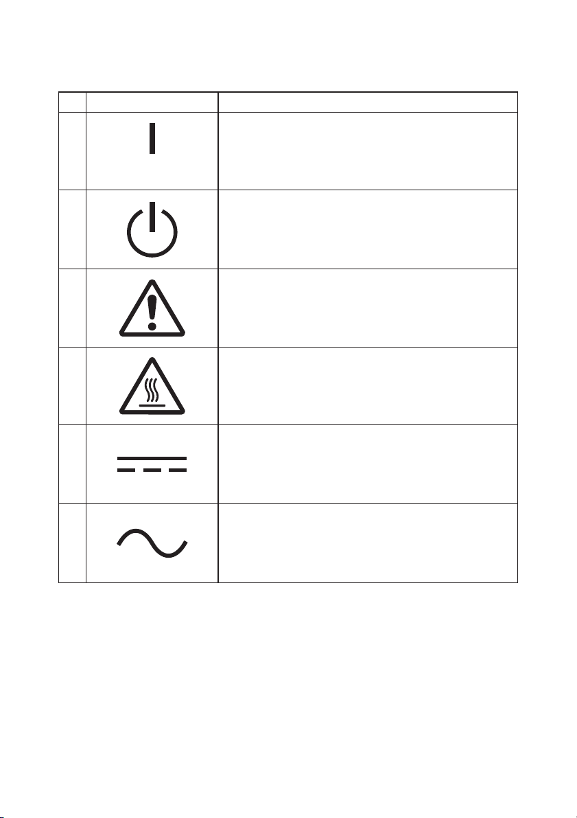
Description of Safety symbols displayed on the equipment
No. Symbol Description
1
"ON" (power)
To indicate connection to the mains, at least for
mains switches or their positions.
2
3
4
5
6
Stand-by
To identify the switch or switch position by means of
which part of the equipment is switched on in order
to bring it into the stand-by condition.
General warning/caution
To identify a general warning/caution.
Caution, hot surface
To indicate that the marked item can be hot and
should not be touched without taking care.
Direct current
To indicate on the rating plate that the equipment is
suitable for direct current only; to identify relevant
terminals.
Alternating current
To indicate on the rating plate that the equipment
is suitable for alternating current only; to identify
relevant terminals.

TABLE OF CONTENTS
1. Appearance and Names of Components ·································································· 4
2. AC Adapter and Thermal Roll Paper ······································································ 6
2-1. AC adapter····································································································· 6
2-2. Paper specification (Thermal paper) ·································································· 6
2-3. Recommended Thermal Paper ·········································································· 7
3. Preparations ······································································································ 9
3-1. Connecting Interface Cable ·············································································· 9
3-2. Connecting the drawer kick cable···································································· 13
3-3. Connecting the AC Adapter ············································································ 14
3-4. Disconnecting the AC Adapter ········································································ 16
3-5. Turning on the Power ···················································································· 17
3-6. Installing the Printer Software ······································································· 17
4. Inserting Paper for Printing ··············································································· 18
4-1. Replacing paper ···························································································· 18
5. Control Panel ··································································································· 27
5-1. Control Panel ······························································································· 27
5-2. Error Indications ·························································································· 27
6. Preventing and Clearing Paper Jams ··································································· 29
6-1. Preventing Paper Jams·················································································· 29
6-2. Clearing a Paper Jam ···················································································· 29
7. Troubleshooting································································································ 30
7-1. Power-on Problems and Errors ······································································· 30
7-2. Cutter-related Problems················································································· 30
7-3. Printing-related Problems ·············································································· 31
8. Regular Cleaning ······························································································ 32
8-1. Cleaning the Paper Holder and Paper Transport ··············································· 32
8-2. Cleaning the Platen Roller ············································································· 33
8-3. Cleaning the Thermal Head ··········································································· 36
8-4. Cleaning the Cutter Blade and Frame ····························································· 37
9. Notes on Use ···································································································· 43
Appendix A: Specifications····················································································· 48
A-1.General Specifications···················································································· 48
A-2.Cutter Specifications······················································································ 50
A-3.Paper Supply Specifications ············································································ 50
A-4.Interface Specifications ·················································································· 50
A-5.Environment Specifications ············································································ 51
A-6.Specifications of Reliability············································································· 52
Appendix B: Interface ··························································································· 53
B-1.Parallel Interface ·························································································· 53
B-2.Dual Interface······························································································· 55
B-3.LAN Interface······························································································· 56
B-4.Drawer Kick Connector ·················································································· 58
B-5.Specifications of Power Supply ········································································ 60
Appendix C: Special Modes ···················································································· 61
C-1.Test Printing ································································································ 61
C-2.Hex Dump ···································································································· 62
C-3.Setting Up the Printer ··················································································· 63
C-4.Setup Items ·································································································· 85
C-5.Sample Print ································································································ 91
3
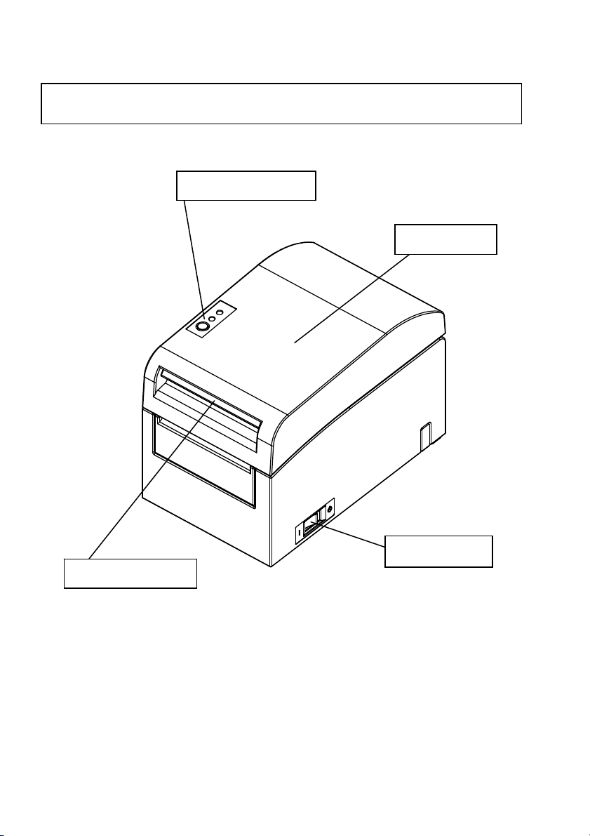
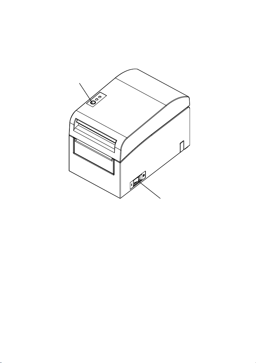
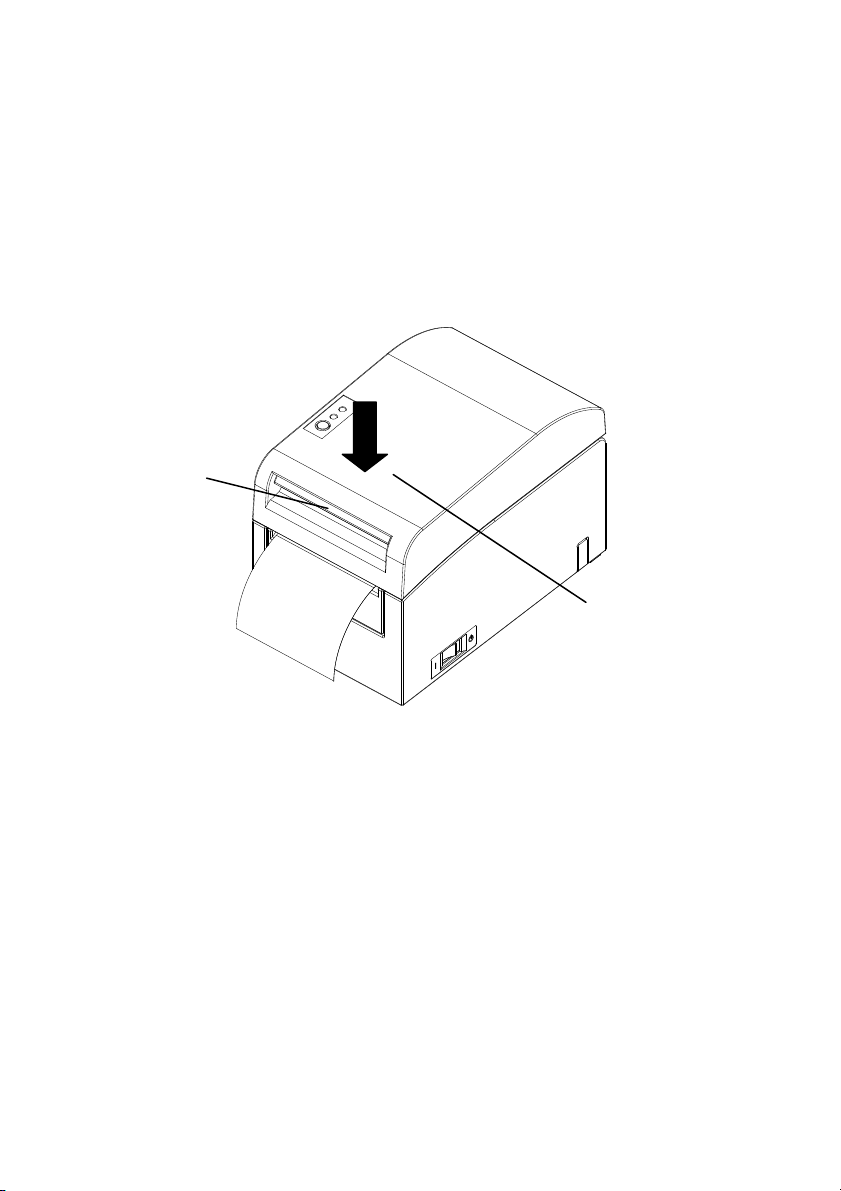
1. Appearance and Names of Components
Control panel
This panel contains status lamps
and operating switches.
Release lever
Pull up the release lever to open the
top cover.
Top cover
Open and close this
cover to replace
forms.
Power switch
This switch turns the
printer power on and off.
4
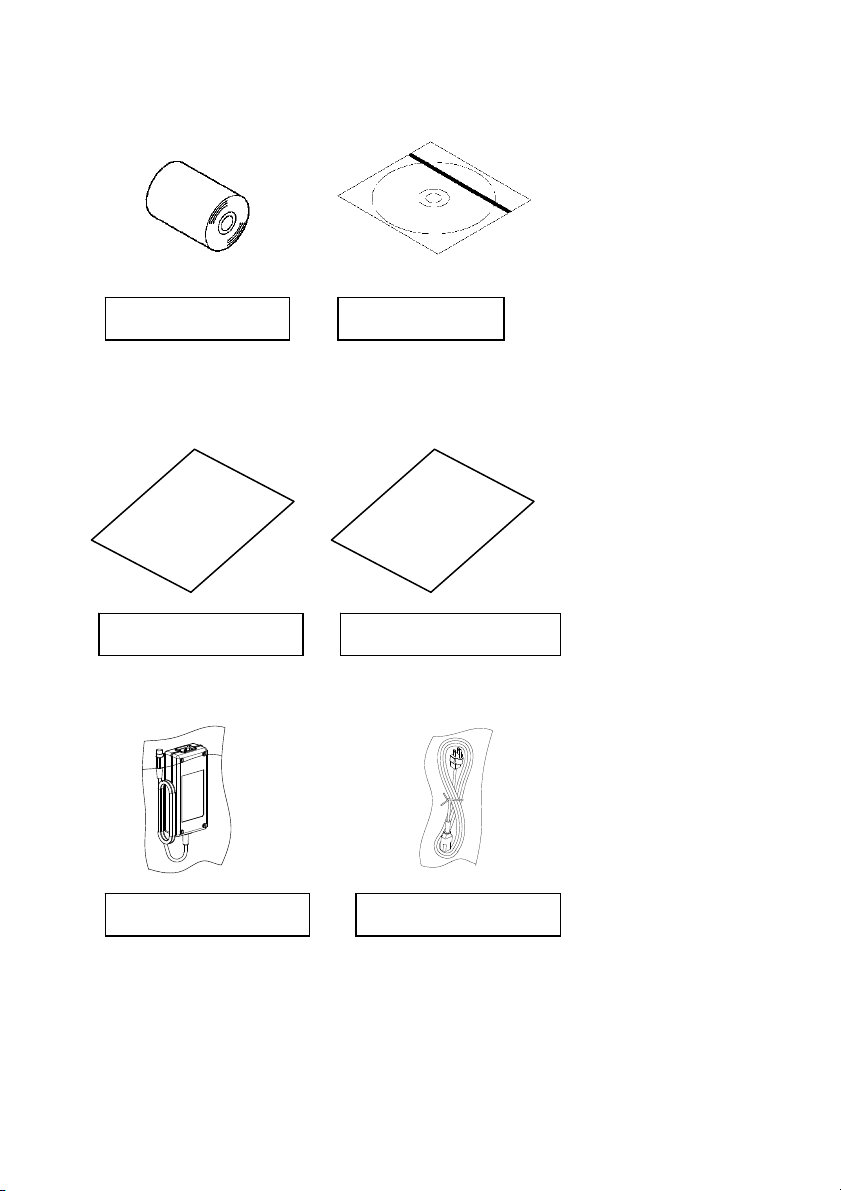
Appended goods
Thermal paper CD
MANUAL
PRINTER DRIVER
UTILITY SOFT
Instruction sheet Safety warranty sheet
AC adapter Power cable
5

2. AC Adapter and Thermal Roll Paper
2-1. AC adapter
Only use the AC adapter specified below.
Model name: KA02951-0120
Input: 100 to 240V AC, 50/60HzOutput: DC24V±5%, 1.5A
Caution: Only use authorized AC adapters.
Caution: Do not use the bundled AC adapter and Power cable for any
electrical equipment other than this printer.
2-2. Paper specification (Thermal paper)
Be sure to use thermal roll paper that conform to the following specifications.
- Paper width: For paper 83mm wide, 83
For paper 60mm wide, 60
0
mm 80mm wide, 80
-1.0
0
mm 58mm wide, 58
-1.0
- Outside diameter: For paper 75 to 90µm thick, 102mm or less
For paper 90 to 150µm thick, 90mm or less
- Core diameter: For paper 75 to 90 m thick, 12±0.5mm (inside)
/18±0.5mm (outside)
For paper 90 to 150µm thick, 25.4±0.5mm (inside)
/32±0.5mm (outside)
- Printed surface: Outside of the roll
- Treatment of end of paper: The roll paper must not be glued to the core. The
end of the paper must also not be folded back.
Note: Do not use rolls that have rough sides or sides from which pieces of paper
extrude. Using such rolls could cause a printer failure.
0
-1.0
0
-1.0
mm
mm
6

2-3. Recommended Thermal Paper
Manufacturer Product
Ltd.
Nippon Paper
Industries Co.,
Ltd.
Mitsubishi
Paper Mills
Limited
name
PD160R Monochrome thermal
PD190R Monochrome thermal
HD75 Monochrome thermal
P220AE-1 Monochrome thermal
PB670 Two-color thermal paper
PB770 Two-color thermal paper
Note: A recommended type of paper must be used. If a type of paper other than a
recommended one is used, head damage, printing irregularities, or similar
problems may occur.
Note: To use two-color thermal paper, set the print color to two colors from the
printer setup menu or using the setup tool contained on the CD-ROM
provided with the printer.
(See "C-3 Setting Up the Printer" in Appendix C, "Special Modes.")
* By setting the appropriate property (use Color on the Graphics tab) for
printing with this printer driver, you can easily print in two-color mode
without having to change the printer setup.
Note: Ruled lines or characters containing fine lines (e.g. a serif typeface) tend to
have dull colors when they are printed on two-color thermal paper. For
printing on two-color thermal paper, a thick font (e.g., a sans serif font) is
recommended.
Quality characteristics Paper
thickness
75m
paper (high-grade
preservation type)
75m
paper (mid-grade
preservation type)
150m
label paper (normal
type)
150m
paper (normal type)
75m
(red/black: normal type)
75m
(blue/black: normal type)
Density
specification
100% Oji Paper Co.,
100%
130%
100%
105%
100%
7

Note: Red or blue printing on two-color thermal paper has an inferior preservation
characteristic that is equivalent to that of normal thermal paper.
Note :Printouts on label paper or thick paper may contain blurs or voids, depending
on the humidity and other environmental conditions. Adjust the print speed
and print density as appropriate for the type of paper used. (See "C-3 Setting
Up the Printer" in Appendix C, "Special Modes.")
In particular, note that the paper transport accuracy may be negatively
affected by printing a barcode in the top margin at the beginning of paper
transport or in the Lower margin at the end of paper transport.
8

3. Preparations
No printer cable is provided with the product. Obtain a printer cable
suitable for the product interface. If you have any questions, consult your
dealer. Before connecting or disconnecting cables, make sure of the
following:
1) The power to the printer and all other devices connected to the
printer is turned off.
2) The AC adapter power cable has been unplugged from the outlet.
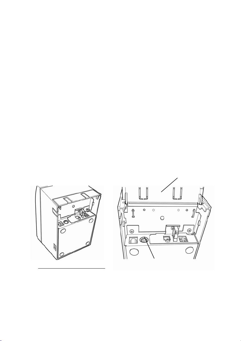
3-1. Connecting Interface Cable
Open the c
onnector cover at the rear of the printer
connect the interface cable to its rear connector socket. Close the cover after
connecting the cable.
Note: If cables are arranged so that they extend from the rear or from the rear on the
right side, remove the inserts in the connector cover or the cover with nippers
or a similar tool. Unless the inserts are removed in this case, the cables may be
damaged and cause a failure.
by pulling it up, and
9
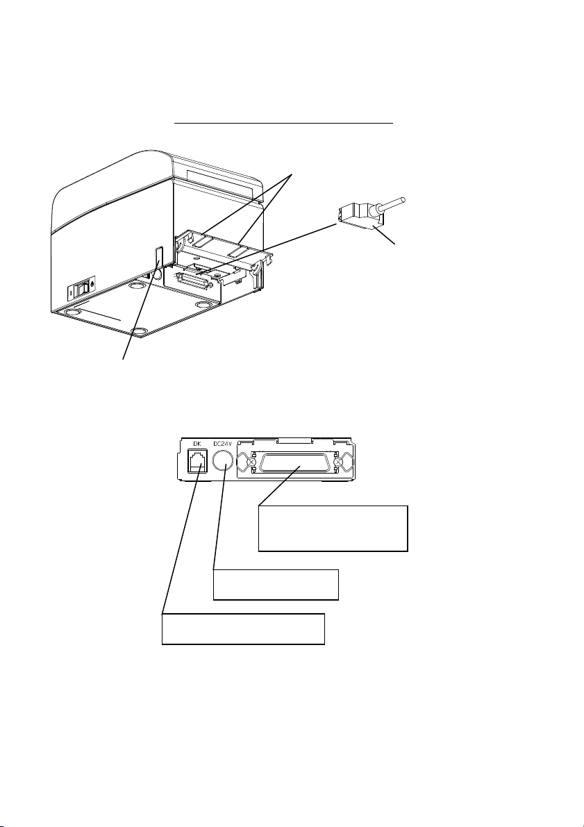
For a unit with parallel interfaces
Connector cover
Insert
Parallel interface cable
* Secure the connector with
clasps after making the
connection.
Insert
Interface connector
(Parallel interface)
Power connector
Drawer kick connector
10
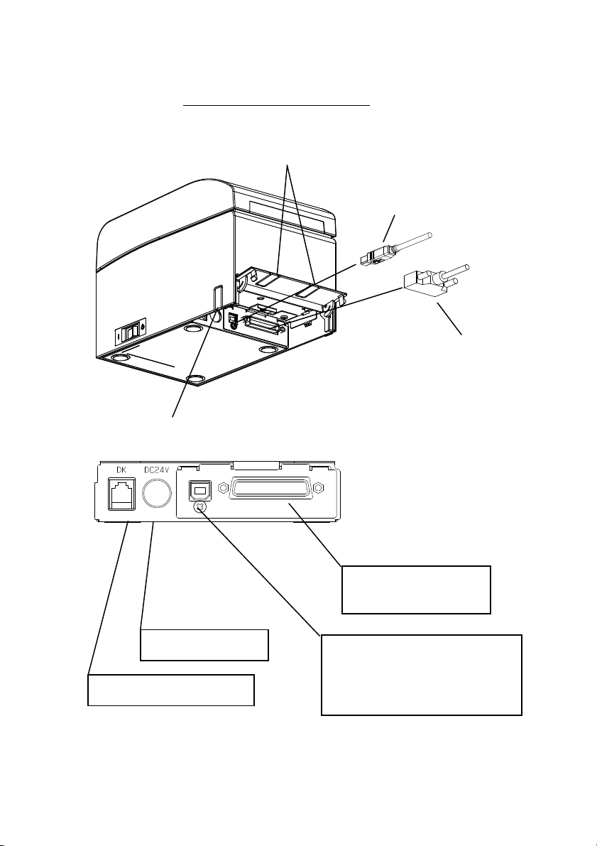
For a unit with Du
al interface
Connector cover
Insert
USB Interface Cable
Type-B
* Connect the printer to a PC
through this connector.
Serial interface cable
* Secure the connector wit
screws after making the
connection.
h
Insert
Interface connector
(Serial interface)
Drawer kick connector
Power connector
11
Interface Connector
(USB Interface Type-B)
* Connect the printer to a PC
through this connector.
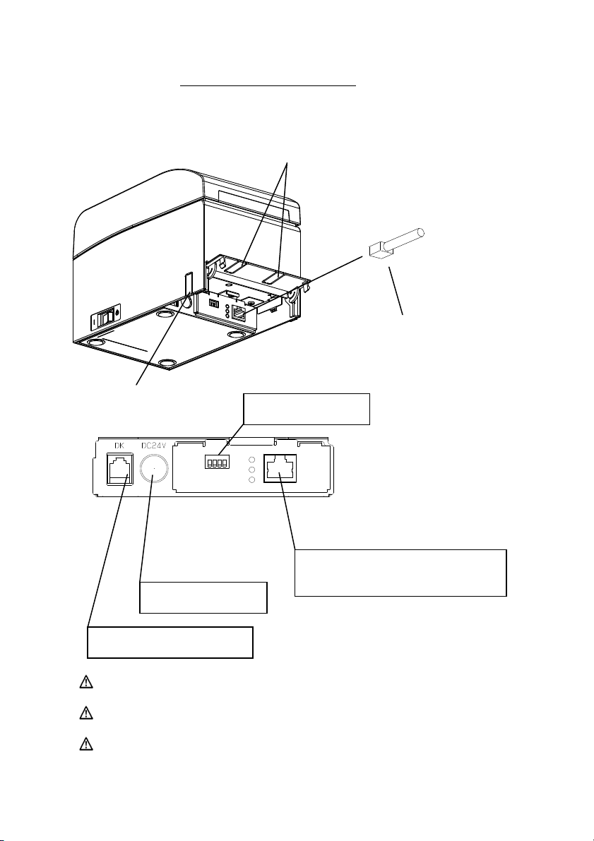
For a unit with LAN interface
Connector cover
Insert
LAN interface cable
Insert
DIP Switch
Interface connector
(LAN interface)
Power connector
Drawer kick connector
Caution: Do not touch the DIP switches during normal use. This may
change the network settings, disabling normal printing.
Caution: If the device is installed vertically, the LAN cable may not usable
due to its shape. Please check before installing.
Caution: The LAN interface cable must use the shield type.
12
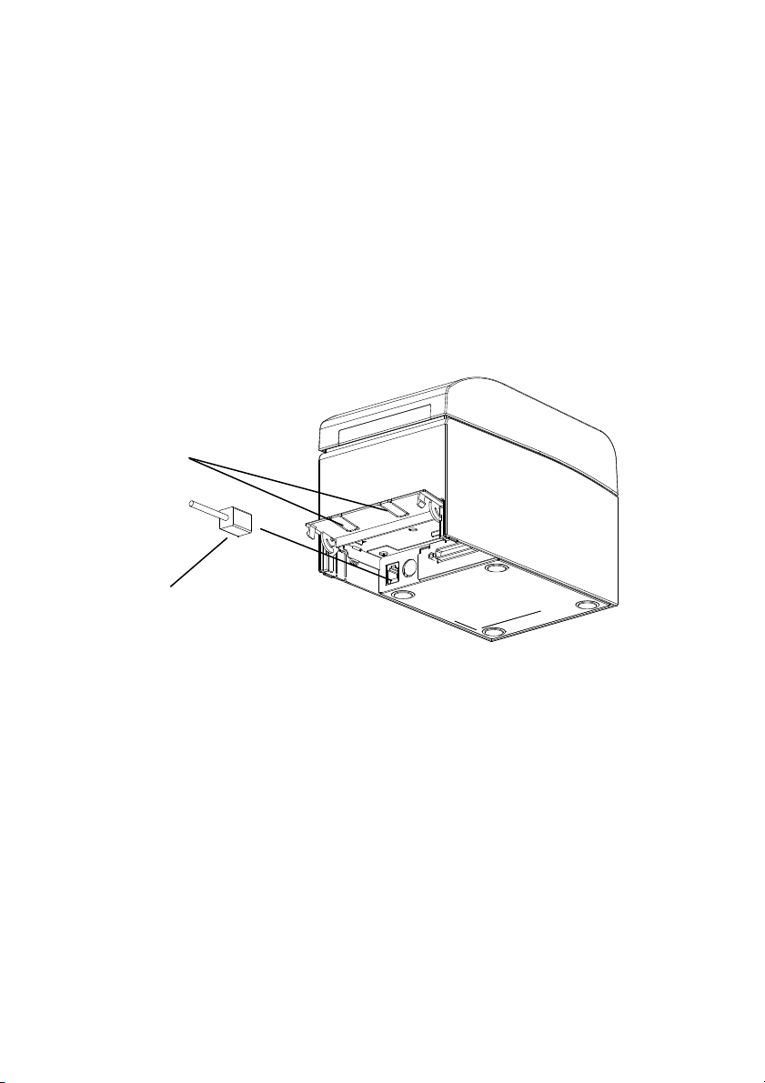
3-2. Connecting the drawer kick cable
Open the connector cover at the rear of the printer by pulling it up, and
connect the drawer kick cable to its rear connector socket. Close the cover
after connecting the cable.
Note : If the cable is arranged so that it extends from the rear, remove the inserts
in the connector cover with nippers or a similar tool. Unless the inserts are
removed in this case, the cable may be damaged and cause a failure.
Note : The drawer kick cable must not be used for a purpose other than for control
of the drawer.
Connector cover
Insert
Drawer kick cable
13
3-3. Connecting the AC Adapter
(1) Connect the AC adapter to the AC adapter power cable.
Note: To connect or disconnect the AC adapter, turn off the power switches of the
printer and all the devices to be connected to the printer. Then, unplug the
plug of the AC adapter power cable from the electrical outlet.
Note: Use only the specified AC adapter and specified AC adapter power cable.
(2) Open the connector cover at the rear of the printer by pulling it up, and
connect the AC adapter cable to the power socket.
Close the cover after connecting the cable.
Note: To connect the AC adaptor, place the printer on its side to make the
connection operation easier to perform.
Note: Remove notch of connector cover with Nipper, to maintain the space for the
cable of AC adapter.
Otherwise, the cable may be damaged and it way cause a failure.
Connector cover
Printer placed on its side
Power connector
14
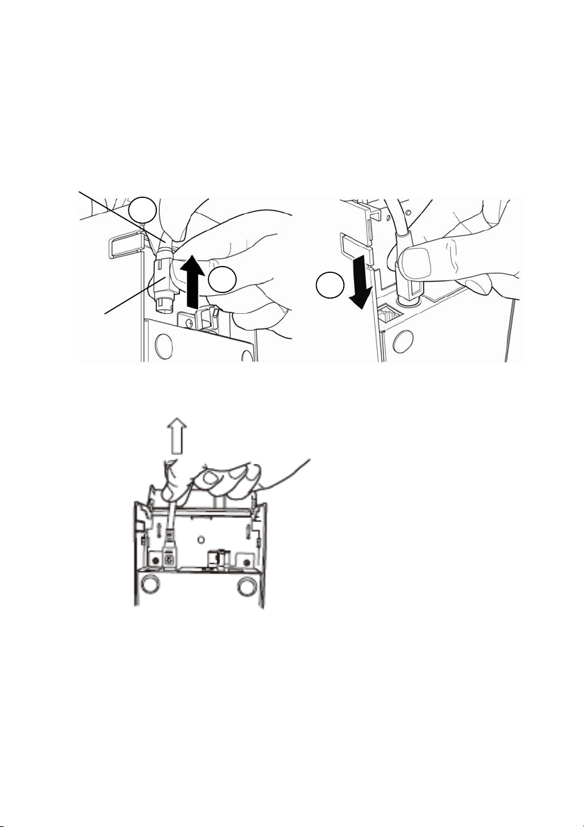
Note: To prevent the adaptor from slipping out, the connector section is
designed to be tight to fit. When inserting, (1) pinch the base of the cable,
(2) while sliding the outer section of the connector upwards, (3) and
insert the connector until it locks in place with a “click” sound.
Base of the cable
Outer section of
the connector
1
2
3
(3) Connect the plug of the power cable to electrical outlet.
(4) Plug the other end of the power cord into the power outlet.
15
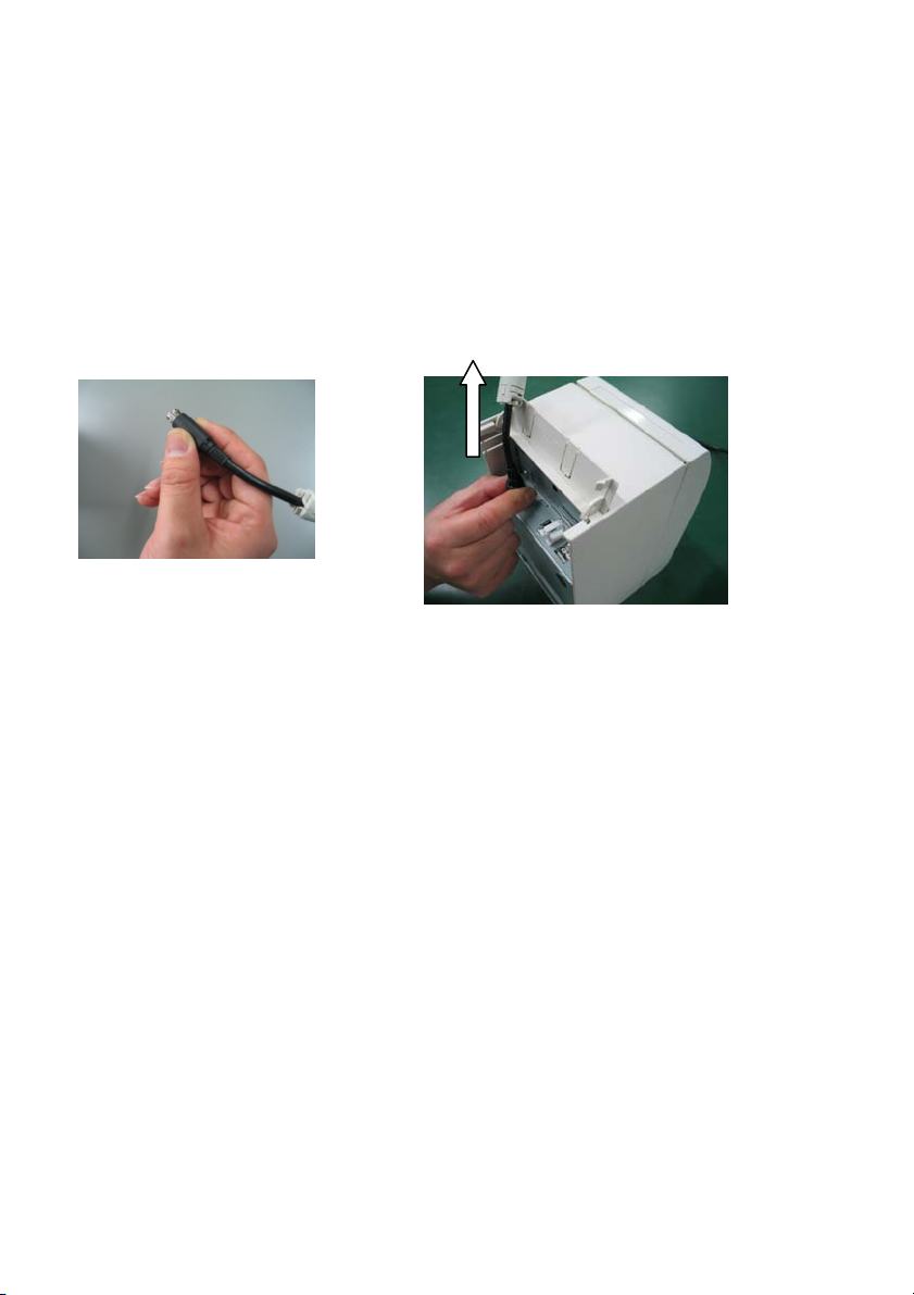
3-4. Disconnecting the AC Adapter
o unplug the AC adapte
T
r cable, grasp the connector as shown in the
picture below and pull it out. The lock mechanism of the connector will
then disengage, and the cable can be unplugged easily. Conversely,
forcibly pulling on the cable itself may damage the connector.
Note: Before disconnecting the AC adapter, switch off the printer and all devices
connected to the printer, and also disconnect the power cable of the AC
adapter from the outlet.
16
3-5. Turning on the Power
After the AC adapter is connected, turn on the power switch at the side of
the printer. The POWER lamp on the control panel lights.
Control panel
Power switch
3-6. Installing the Printer Software
Referring to the "Installation Guide"
(\Manuals\PT390_InstallGuide1_en.pdf) contained on
the CD-ROM provided with the printer, install the printer driver and
utility software.
17
4. Inserting Paper for Printing
4-1. Replacing paper
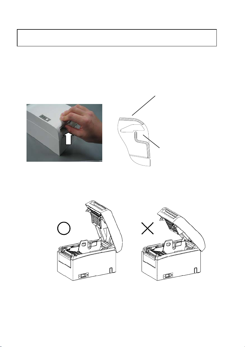
(1) Grasp the top cover, pull up the cover release lever, and
open the top cover.
Top part of the top cover
▼
▲
Bottom part of the cover
release lever
(2) When manipulating the top cover, note that the cover seems to
lock in p
osition before it is open completely. Make sure that the
cover is really open completely as shown in the picture below.
Note: If the top cover is not open completely during maintenance, it may close
inadvertently.
18
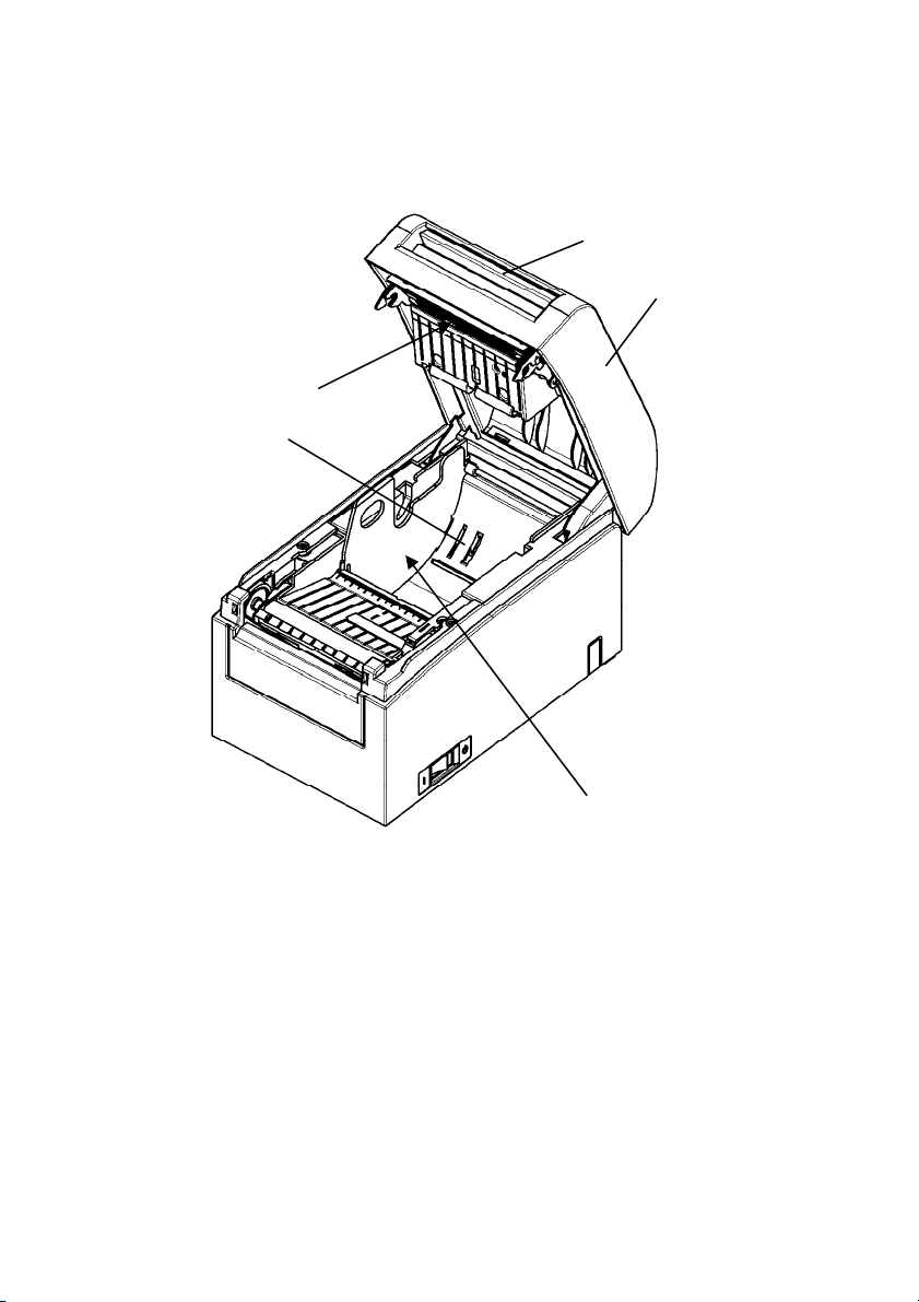
Note: Do not touch the thermal head. Doing so m
electricity.
Thermal head
Roll holder
ay result in damage from static
Release lever
Top Cover
19
Separator
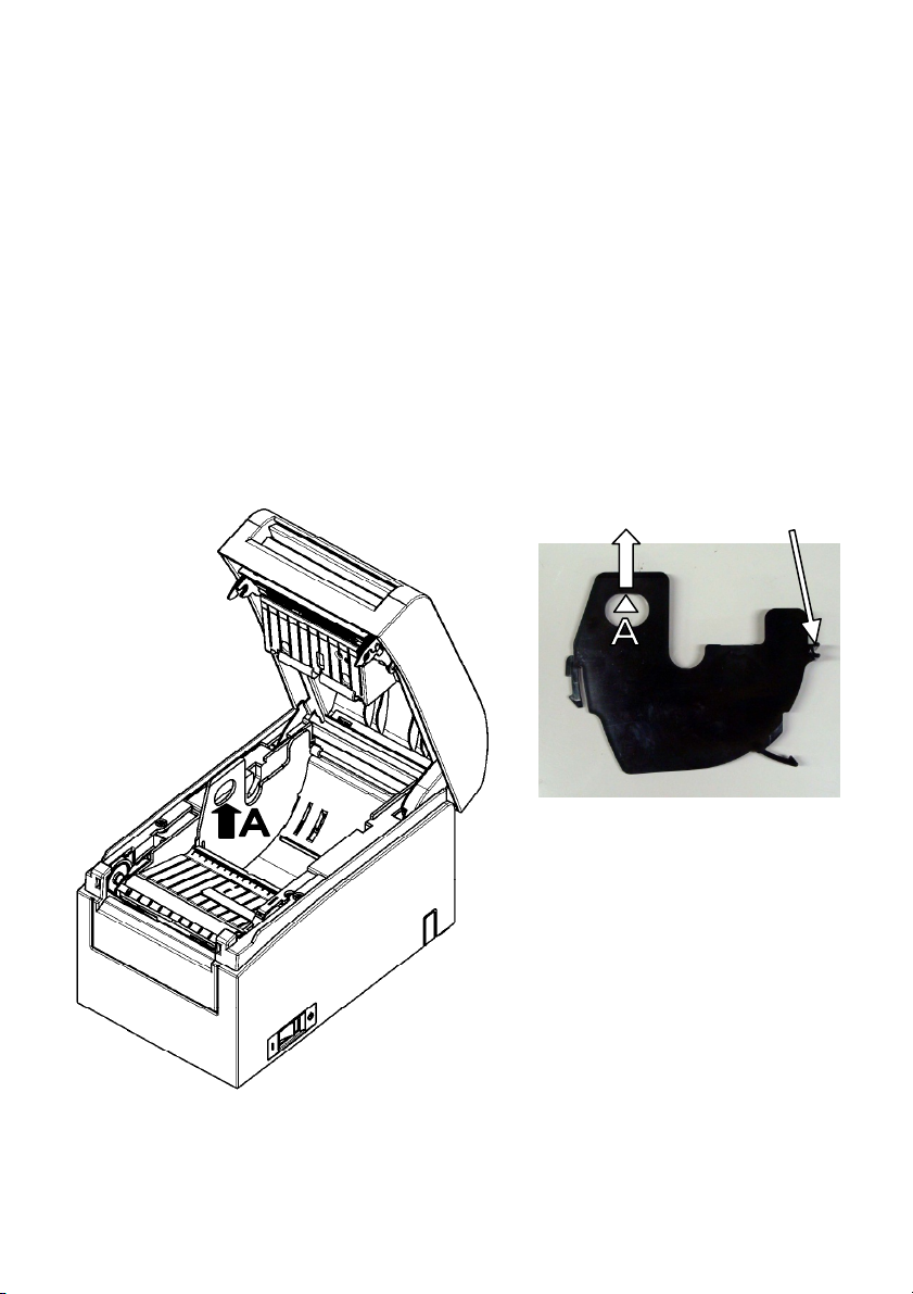
(3) Adjust the separator to the width of the roll paper. For roll paper
with a width of 80 mm, the separator need not be removed. For roll
paper with a width of 70, 60, or 58 mm, remove the separator and
attach it again at the correct width. For roll paper with a width of
83 mm, remove the separator completely.
Note: At the time of shipment from the factory, the separator is set at a position
appropriate for a paper width of 80 mm.
How to remove the separator
From the location indicated by A, lift the separator.
Rear hook
for the axis
Separator
20
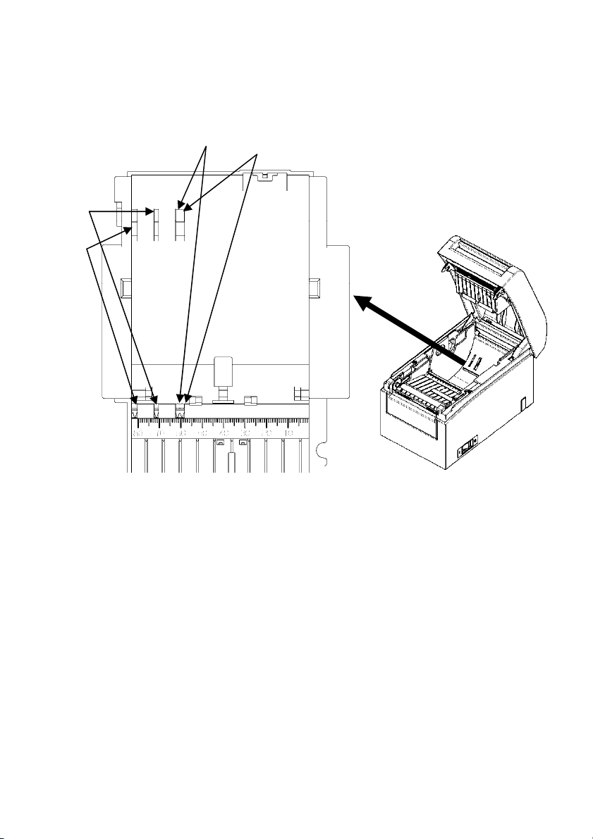
(4) Set the separator to a position appropriate for the width of
the roll paper, as shown below.
60 mm
58 mm
70 mm
80 mm
Separator setting in detail
Note : Adjust the separator to the width of the roll paper. To use roll paper with a
width of 83 mm, remove the separator.
Note : When using roll paper with a width of 58 or 60 mm, take care not to set the
separator at an angle.
Note : When replacing the separator, set a paper width appropriate to the print
area, referring to Appendix C, "Special Modes."
(See "C-3 Setting Up the Printer" in Appendix C, "Special Modes.")
21
58 mm setting groove
60 mm setting groove
Roll pape
r width of 58 mm Roll paper width of 60 mm
70 mm setting groove
80 mm setting groove
Roll paper width of 70 mm
Roll paper width of 80 mm
22
How to attach the separator
Attach the separator at the rear hook for the axis.
Rear hook for the axis
Aligned horizontally
Note : Push the separator down until it engages with an audible click, and confirm
that the top of the separator is aligned horizontally.
Note : When using roll paper with a width of 58 or 60 mm, take care not to set the
separator at an angle.
Note : When replacing the separator, set a paper width appropriate to the print
area, referring to Appendix C-3 Setting Up the Printer" in Appendix C,
"Special Modes."
23
(3) When using a new paper roll, remove the glued portion of the
paper as well as the part to which adhesive tape is affixed.
Note: Since the glued portion of the paper should not be printed on, remove about
one turn (about 40 cm) of the roll paper from the beginning so that none of
the remaining paper has glue on it.
Any adhesive or other matter remaining from the glue may adhere to the
thermal head and cause a problem, such as voids on printouts. Therefore, do
not forget to remove the glued portion of the paper.
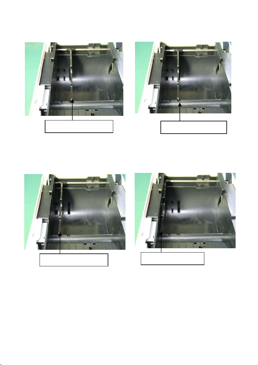
(4) From the front of the printer, pull out the end of the paper as shown
below.
Note: Pull out the paper until enough of it protrudes past the front cover of the
printer.
24
Paper not protruding
from the front cover
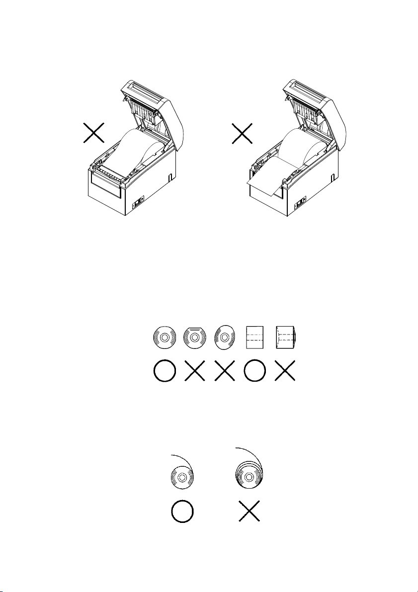
Note : Before loading a new roll, make sure that an old core does not remain in the
roll holder. Leaving an old core will cause a paper-near-end error condition.
Note : The roll paper must have no deformities. Using roll paper such as that
shown in the figure below may cause a paper jam, uneven printing, or
other printing problem.
Roll paper inserted
upside down
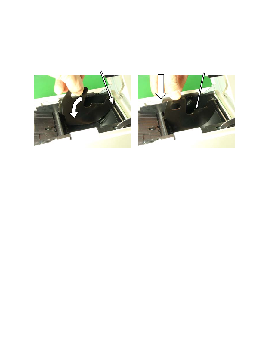
Note : If the loaded roll paper is loose (slack) as shown below, take up the slack
before printing on the paper. Printing on roll paper that is loose may cause
a paper jam, uneven printing, or other printing problem, which will
prevent the printer from detecting paper near end conditions.
25
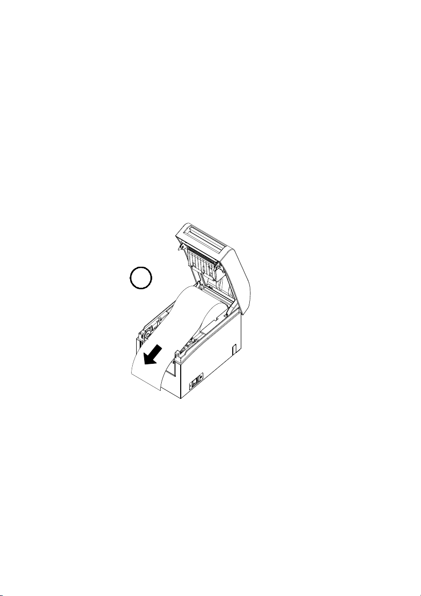
(5) Place the paper in the correct orientation, and carefully close the top cover.
Note : Place the paper in the correct orientation. If the top cover is closed while the
paper is not correctly in place, a paper jam or misaligned printing might
occur.
Note : To close the top cover, press it down near its center (the location pointed at
in the figure below) until you hear the lock engage. If the cover is not
completely locked, printing might be impossible.
Press
here
Release lever
Top cover
26
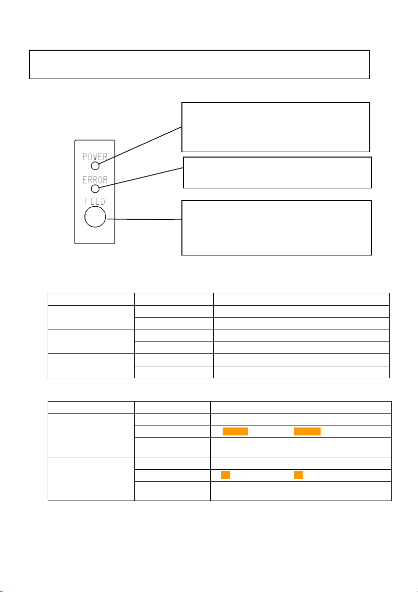
5. Control Panel
5-1. Control Panel
5-2. Error Indications
Recoverable errors
Error condition
No paper
(paper end)
Cover open
Head hot (*1)
*1 Printing is suspended because of a high thermal head temperature.
LED LAMP
POWER (●)
ERROR (●)
POWER (●)
ERROR (●)
POWER (●)
ERROR (●)
Error condition
Paper near end
Black mark error
(*1)
*1 Applicable only if the printer supports sensing of black marks
LED LAMP
POWER (●)
ERROR (●)
POWER (●)
ERROR (●)
POWER lamp (●)
Lights when the power switch is turned
on and power is supplied to the printer.
ERROR lamp (●)
Lights or blinks to indicate errors.
FEED switch
Pressing this switch once advances the
paper one line. Holding down this switch
advances paper continuously.
Constantly on
Constantly on
Constantly on
Constantly on
Constantly on
Constantly on
Constantly on
●●●●――――●●●●――――
Repeated blinking of the amber lamp four
times in succession
Constantly on
●●――――――●●――――――
Repeated blinking of the amber lamp four
times in succession
Blinking pattern
Blinking pattern
27

Unrecoverable errors
Error condition LED LAMP Blinking pattern
Internal error
Head not
installed
Low voltage
Over voltage
Cutter
functioning
abnormally
LF motor
functioning
abnormally
POWER (●)
ERROR (●)
POWER (●)
ERROR (●)
POWER (●)
ERROR (●)
POWER (●)
ERROR (●)
POWER (●)
ERROR (●)
POWER (●)
ERROR (●)
――●―●―
●―――――
Repeated pattern in which the green lamp
blinks twice and the amber lamp blinks once
――●―●―●―
●―――――――
Repeated pattern in which the green lamp
blinks three times and the amber lamp blinks
once
――●―●―●―●―
●―――――――――
Repeated pattern in which the green lamp
blinks four times and the amber lamp blinks
once
――●―●―●―●―●―
●―――――――――――
Repeated pattern in which the green lamp
blinks five times and the amber lamp blinks
once
――●―●―●―●―●―●―
●―――――――――――――
Repeated pattern in which the green lamp
blinks six times and the amber lamp blinks
once
――●―●―●―●―●―●―●―
●―――――――――――――――
Repeated pattern in which the green lamp
blinks seven times and the amber lamp
blinks once
28

6. Preventing and Clearing Paper Jams
6-1. Preventing Paper Jams
Do not touch the paper while the paper is being ejected or cut.
Holding or pulling the paper by hand during ejection might cause
a paper jam, incorrect cutting, or a feed error.
6-2. Clearing a Paper Jam
If a paper jam occurs, re
move the jammed paper as fol
(1) Turn off the printer power by turning off the power switch.
(2) Press the cover open lever down, and open the top cover.
(3) Pull out the jammed paper slowly toward the top while holding down
the printer, as shown in the picture below.
Note: Do not pull the paper with excessive force.
Note: Do not touch the thermal head. Doing so may result in damage from static
electricity.
lows:
29

7. Troubleshooting
This chapter describes the appropriate action to be taken in cases
where the printer is not operating correctly or fails to produce
clean printouts.
7-1. Power-on Problems and Errors
Symptom Cause Corrective action
Although the power
has been turned on,
the POWER lamp on
the control panel does
not light and the
printer does not start
up.
The ERROR lamp on
the control panel is lit,
and the printer does
not work.
(1) The power cable is
(2) The connector of the
AC adapter is
disconnected.
(1) No paper is inserted.
(2) The top cover is not
closed completely.
(3) The thermal head is at
a high temperature.
7-2. Cutter-related Problems
Symptom Cause Corrective action
Paper cannot be
cut.
The cutter does not
return to the correct
position.
(1) The cutter blade is
damaged or worn, or it
has been used for too
long.
(2) Paper fragments or
other foreign matter is
stuck around the
cutter blade or paper
chute.
(3) Adhesive matter is
adhering to the cutter
blade because of
printing on label
paper.
Paper fragments or other
foreign matter is stuck
around the cutter blade
or paper chute.
(1) Connect the power cable.
disconnected.
(2) Connect the connector of
the AC adapter.
(1) Insert paper.
(2) Close the top cover
completely.
(3) Wait until the thermal
head temperature
decreases sufficiently.
(1) Turn off the power, and ask
for repairs.
(2) Remove the paper
fragments or foreign
matter.
(3) Clean the cutter blade to
remove the adhesive
matter.
Remove the paper
fragments or foreign
matter.
30

7-3. Printing-related Problems
(
(
(
Symptom Causes Corrective action
Printing does not
begin.
The printing is too
dark or blurry.
Printed characters
are thin (faint).
The print density is
uneven.
Vertical marks
appear on the
printout.
(1) The interface cable is
disconnected or broken.
(2) The printer setup is
incorrect.
(1) The print density setting
included in the printer
setup is incorrect.
(2) The thermal head is
damaged.
(1) The print density setting
included in the printer
setup is incorrect.
(2) The thermal head is
damaged.
(1) Paper fragments or
foreign matter is stuck
on the heating elements
of the thermal head.
(2) The printer setup is
incorrect.
(3) Foreign matter is
adhering to the platen
roller.
(4) The thermal head is
damaged.
1) Foreign matter is stuck
or caught on the paper
transport.
2) Foreign matter is
adhering to the thermal
head
3) The thermal head is
damaged.
(1) Connect the interface cable
correctly, or replace it.
(2) Set up the printer correctly.
Example: An incorrect baud
rate is set.
(See "C-3 Setting Up the
Printer.")
(1) Adjust the print density and
print speed settings of the
printer so that they are
appropriate to the paper.
(See "C-3 Setting Up the
Printer.")
(2) Turn off the power, and ask
for repairs.
(1) Adjust the print density and
print speed settings of the
printer so that they are
appropriate to the paper.
(See "C-3 Setting Up the
Printer.")
(2) Turn off the power, and ask
for repairs.
(1) Check and clean the thermal
head.
(2) Adjust the print density and
print speed settings of the
printer so that they are
appropriate to the paper.
Set up the printer correctly.
(See "C-3 Setting Up the
Printer.")
(3) Remove the foreign matter
from the platen roller.
(4) Turn off the power, and ask
for repairs.
(1) Clean the paper transport.
(2) Clean the thermal head.
(3) Turn off the power, and ask
for repairs.
31

8. Regular Cleaning
Printed characters may not be completely formed if paper residue, dust, or
a similar material is present. To ensure proper printing, remove any paper
residue and dust on the paper holder, paper transport components, platen
roller, and surface of the thermal head. Cleaning is required monthly.
Note: Before starting cleaning, turn off the printer power switch.
8-1. Cleaning the Paper Holder and Paper Transport
With a dry soft cloth, wipe the paper holder and paper transport to
remove dust, paper particles, adhesive, and other foreign matter.
32

8-2. Cleaning the Platen Roller
The cleaning procedure is as follows.
(1) With paper inserted in the printer, turn off the printer power
switch once, and turn on the switch again while holding down
the FEED switch on the control panel. Then, the data shown
below is printed.
TEST PRINT
END
SAMPLE PRINT
CUTTER CLEANING
PLATEN ROLLER CLEAING
SET UP
HEX DUMP
TEST PRINT
ITEM SELECTION :FEED switch pushed short.
ITEM DECSION :FEED switch pushed short.
SPECIAL MODE
SELECTION ITEM
Paper feed direction
(2) Press the FEED switch briefly (one second or less) three times to
move to "PLATEN ROLLER CLEANING."
ATEN ROLLER CLEANING
PL
↑
UP
SET
↑
HEX DUMP
↑
TEST PRINT
END
SAMPLE PRINT
CUTTER CLEANING
PLATEN ROLLER CLEAING
SET UP
HEX DUMP
TEST PRINT
ITEM SELECTION :FEED switch pushed short.
ITEM DECSION :FEED switch pushed short.
SPECIAL MODE
SELECTION ITEM
Paper feed direction
33

Then, press and hold down the FEED switch for one second or
longer to accept the selection. The printer enters platen roller
cleaning mode. The printer prints the following and cuts the
paper when it enters platen roller cleaning mode:
PLATEN ROLLER CLEANING MODE
Paper feed direction
1. Open Cover, and remove Roll Paper.
2. Push FEED switch to move
Platen Roller to the cleaning position.
3. When cleaning is completed, set
Roll Paper, and close Cover
(3) Open the top cover, and remove the roll paper.
(4) Press the FEED switch to rotate the platen roller to a position
that will facilitate cleaning, and then wipe the platen roller with
a dry soft cloth to remove paper particles, adhesive, and other
foreign matter from the surface of the platen roller.
Platen roller
34

(5) After completing cleaning, reposition the roll paper, and close the
top cover.
Note : Take care not to dent or otherwise damage the platen roller.
A dent on the platen roller may result in incomplete printing or line feed
errors.
Note : Each time that the FEED switch is pressed, the platen roller is rotated by
1/12 of a turn.
35

8-3. Cleaning the Thermal Head
(1) Before attempting to clean the thermal head, be sure to turn off the
printer power switch.
(2) Open the top cover.
Using an alcohol solvent, remove black paper particles and other
(3)
residue from the surface of the thermal head. If the printer printed
on label paper, any adhesive matter adhering to the surface of the
thermal head must be removed.
Thermal head
No
te : The thermal head is susceptible to damage. When cleaning it, use a soft
cloth and be especially careful not to damage the head.
Note : Immediately after printing, the thermal head is hot. Before cleaning the
head, allow the head enough time to cool.
Note : Because the thermal head is susceptible to damage by static electricity,
take precautions to prevent the generation of static electricity.
Note : Do not turn on the printer until all alcohol has dried.
Note : Do not use a solvent other than ethyl or isopropyl alcohol.
36

8-4. Cleaning the Cutter Blade and Frame
If the printer printed on full-sheet label paper, any adhesive
matter adhering to the cutter blade and frame must be removed.
Even when label paper has been cut normally, clean the cutter blade
at an interval of about once a month to ensure stability in cutting.
Note: Although the edge of the cutter blade is not as sharp as the edges of utility
knives generally used in offices, there is a risk of injury to a hand or finger
that is moved while pressed against the cutter blade edge. Take care to
avoid injury when cleaning the cutter blade.
Items required for cleaning
- Flathead screwdriver (small) Cleaning sheet
- General-purpose utility knife (Product No.: 0631260)
37

The cleaning procedure is as follows.
A
(1) With paper inserted in the printer, turn off the printer power
switch once, and turn on the switch again while holding down
the FEED switch on the control panel. Then, the data shown
below is printed.
Note: If you have passed the item that you want to select, repeatedly press the
FEED switch briefly until you return to the first item.
TEST PRINT
END
SAMPLE PRINT
CUTTER CLEANING
PLATEN ROLLER CLEAING
SET UP
HEX DUMP
TEST PRINT
ITEM SELECTION :FEED switch pushed short.
ITEM DECSION :FEED switch pushed short.
SPECIAL MODE
SELECTION ITEM
Paper feed direction
(2) Press the FEED switch briefly (one second or less) four times to
move to "CUTTER CLEANING."
CUTTER CLE
↑
PLATEN ROLLER CLEANING
↑
SET UP
↑
HEX DUMP
↑
TEST PRINT
ITEM SELECTION :FEED switch pushed short.
ITEM DECSION :FEED switch pushed short.
SPECIAL MODE
NING
END
SAMPLE PRINT
CUTTER CLEANING
PLATEN ROLLER CLEAING
SET UP
HEX DUMP
TEST PRINT
SELECTION ITEM
Paper feed direction
38

Then, press the FEED switch for one second or longer to accept
the selection. The printer enters cutter cleaning mode. The
printer prints the following and cuts the paper when it enters
cutter cleaning mode:
CUTTER CLEANING
1. Open Cover, and remove Roll Paper.
2. Push FEED switch to move Cutter to
the cleaning position.
3. When cleaning is completed, set
Roll Paper, and close Cover
Paper feed direction
(4) Press the FEED switch to move the cutter to a position that will
facilitate cleaning, and then clean the cutter.
(5) After completing cleaning, reposition the roll paper, and close the
top cover.
39

- Cleaning the Upper cutter
Using a general-purpose utility knife, flathead screwdriver, or
similar tool, remove the adhesive matter adhering to the inner
side and edge of the Upper cutter.
Note: Be very careful not to damage the edge of the Upper cutter when handling
the utility knife or screwdriver. Also take care not to dent or otherwise
damage the platen roller. A dent on the platen roller may result in
incomplete printing or line feed errors.
Upper cutter
Using the cleaning sheet or a similar material, wipe off the
adhesive matter adhering to the Upper cutter.
Upper cutter
Note: Although the edge of the Upper cutter is not as sharp as the edges of the
utilit
y knives generally used in offices, there is a risk of injury to a finger
that is moved while pressed directly against the edge of the cutter.
40

- Cleaning the Lower cutter
Using a general-purpose utility knife, flathead screwdriver, or similar tool,
remove the adhesive matter adhering to the surface and edge of the Lower
cutter.
Note: Be very careful not to damage the edge of the Lower cutter when handling
the utility knife or screwdriver. Also take care not to dent or otherwise
damage the platen roller. A dent on the platen roller may result in
incomplete printing or line feed errors.
Lower
cutter
41

Using the cleaning sheet or a similar material, wipe off the adhesive
matter adhering to the Lower cutter.
Lower
cutter
No
te: Although the edge of the Lower cutter is not as sharp as
knives generally used in offices, there is a risk of injury to a finger that is
moved while pressed directly against the edge of the cutter.
the edges of utility
(5) After completing cleaning, reposition the roll paper, and close the
Top cover.
Note: Be careful when the printer is in cutter cleaning mode, because the Upper
cutter is exposed. After completing cleaning, reposition the roll paper, and
close the Top cover.
42

9. Notes on Use
(1) Printing at a high rate might result in unclear printing. If this problem occurs,
adjust the printing rate. Alternatively, adjust the print speed and print density so
that there are no blurs.
(See "Appendix C-3 Setting Up the Printer" in Appendix C, "Special Modes.")
(2) Printing characters from a non-standard character set e.g. in a thin serif font will
result in the characters appearing very faint. Use a bold sans serif font.
(3) For quality printing that is free from uneven spacing and condensed or elongated
printing after paper is cut or printing is paused, resume printing following a paper
feed of at least 1 mm (8 dots).
(4) If the data transfer rate is too low, serial printing may result in uneven print
density (vertical white marks may appear on printouts) because of repeated
printing and pausing. If priority is placed on print quality, use batch printing
mode.
(See "Appendix C-3 Setting Up the Printer" in Appendix C, "Special Modes.")
(5) The upper margin can be set to 12mm or 4.5mm with a command. If the upper
margin is set to 4.5mm, reverse feeding of the paper takes place before the next
printing operation. The paper must therefore be removed after each printing and
cutting operation. If the paper is not removed, the part connected to the roll in
partial cutting could be torn off, or the part that has been cut could be folded back.
Note also that the paper length used per transaction must be at least 30mm.
(6) Printing at a high print density (110% or higher) may cause blurs or uneven print
density on printouts under low-temperature conditions, depending on the print
pattern. If priority is placed on print quality, use a lower print speed.
(See "Appendix C-3 Setting Up the Printer" in Appendix C, "Special Modes.")
(7) Since the difference in hue between red and black or blue and black may not be
noticeable when two-color thermal paper is used, be sure to confirm in advance the
color of the printed characters.
(8) When roll paper with a width of 83 mm is used, characters that are too close to the
(left or right) edge of the paper may not be printed because of inaccuracies in
tracking. Be sure to set a margin of sufficient width.
(9) Do not switch from narrow paper to wide paper (e.g., from paper that is 58 mm
wide to paper that is 80 mm wide) during operation. When narrow paper is used,
the thermal head area where there is no paper comes in direct contact with the
platen roller, and the resulting wear on the head may lead to a deterioration in
print quality. Similarly, if the paper width is changed, the cutter blade will cut at
a location that has no paper, and the resulting wear on the blade may lead to
improper cuts. To switch from narrow paper to wide paper, exchange the thermal
head and the cutter blade.
43

(10) If label paper is used, adhesive matter adhering to the cutter blade, thermal head,
paper transport, or paper holder may cause a cutting error, print error, or paper
transport error. Remove adhesive matter periodically (typically on a monthly
basis).
(11) If paper is left inserted in the printer for a long time, the paper may become
deformed and result in thin (faint) printed characters. Before starting printing in
such cases, feed the paper by 20 to 30 mm.
(12) If the type of paper used is other than the recommended ones, the print quality and
thermal head life are not guaranteed. In particular, if the type of thermal paper
contains Na+, K+, or Cl-, the thermal head life may be significantly shortened.
44

Notes on using the cutter
(1) In full cutting mode, the length of paper per transaction must be within a
range of 58 to 180 mm. If a different paper length is used, the printed paper
may not drop from the paper transport, thus causing a cutting error.
(2) The maximum number of successive cuts by the cutter is 30 cuts per minute
(at least two seconds per cut). Using the cutter at a higher rate may cause a
failure.
(3) Do not pull the paper during cutting. Doing so may cause a paper jam or
another problem.
(4) Each time that a sheet of paper is cut in full cutting mode, the sheet of paper
must be removed.
Notes on printing of barcodes and two-dimensional codes
(1) Barcodes that are rotated 90 degrees or aligned vertically when printed may
not be readable. Verify the readability in advance.
(2) Printouts on label paper or thick paper may contain blurs, depending on
humidity and other environmental conditions. Adjust the print speed and
print density appropriate for the type of paper used, and verify the
readability in advance.
(See "Appendix C-3 Setting Up the Printer" in Appendix C, "Special
Modes.")
(3) The recognition ratio of two-dimensional codes (QR codes, PDF417, and
DataMatrix) varies depending on various factors, including the module
width, print density, ambient temperature, thermal roll paper type, and
reader performance. Adjust the print speed and print density appropriate to
printing two-dimensional codes, and verify the readability in advance.
(See "Appendix C-3 Setting Up the Printer" in Appendix C, "Special
Modes.")
(4) The paper transport accuracy may be negatively affected by printing a
barcode in the Upper margin at the beginning of paper transport or in the
Lower margin at the end of paper transport. Verify the readability before
starting printing.
45

Notes on using the printer through the USB interface
(1) The printer must be connected directly to the host computer.
(2) Before starting printing, turn on the power to the printer.
(3) If a printer error occurs during printing, recover the printer from the error,
and then retry printing.
(4) The host computer should not be set to any of the following modes: standby,
sleep, suspend, and pause.
If the host computer or printer does not work normally after the host
computer returns to normal operation mode from one of the above modes,
disconnect the USB cable once and then reconnect it, or turn off the printer
power switch once and then turn on the switch again. If the host computer
or printer cannot be restored to normal operation after the cable is
reconnected or power switch is turned on again, restart the host computer.
(5) The USB hub function cannot be used when the power to the printer is off.
(6) If a peripheral device connected to the USB hub is not recognized, perform
one of the following operations:
- Disconnect the USB cable from the peripheral device once, and then
reconnect it.
- Connect the peripheral device to the other port of the USB hub.
(7) The operation of connected USB devices is not guaranteed. Before using a
USB device, verify its operation yourself.
Note: Do not turn off the power to the printer during printing.
If you inadvertently turn off the power to the printer during printing and
the printer then fails to work normally, restart the host computer.
46

Note on installation
(1) The printer must be used indoors. If used outdoors, the printer may fail
because of dust.
Note on the modular connector
(1) This product uses a modular connector as a dedicated connector for the cash
drawer or customer display terminal. The connector must not be connected
with a connector that leads to a public switched line or other such destination.
Note on using the printer in special mode
(1) If a large diameter roll is used, paper may fold or unusual noises may be
heard. To prevent these problems, use a roll with a small diameter (50mm
or less). If a Windows PC is used as the host system, a utility program can be
used to make settings.
Windows® is a registered trademark of Microsoft Corporation in the United
States and/or other countries.
47

Appendix A: Specifications
A-1.General Specifications
(1) Print method: Direct line thermal printing system
(2) Maximum print speed: 300mm/s (single-color thermal paper)
115mm/s (two color thermal paper)
(3) Dot resolution: 8 dots/mm (0.125mm)
(4) Relationship between number of print columns and character size
ANK: Font A 32 columns: 12x24 35 columns: 12x24 36 columns: 12x24
ANK: Font B
ANK: Font C 48 columns: 8x16 52 columns: 8x16 54 columns: 8x16
Kanji: Font A 16 columns: 24x24 17 columns: 24x24 18 columns: 24x24
Kanji: Font B 19 columns: 20x24 21 columns: 20x24 21 columns: 20x24
Kanji: Font C 24 columns: 16x16 26 columns: 16x16 27 columns: 16x16
ANK: Font A
Extension Font
ANK: Font B
Extension Font
ANK: Font A 42 columns: 12x24 48 columns: 12x24 53 columns: 12x24
ANK: Font B
ANK: Font C 64 columns: 8x16 72 columns: 8x16 80 columns: 8x16
Kanji: Font A 21 columns: 24x24 24 columns: 24x24 26 columns: 24x24
Kanji: Font B 25 columns: 20x24 28 columns: 20x24 32 columns: 20x24
Kanji: Font C 32 columns: 16x16 36 columns: 16x16 40 columns: 16x16
ANK: Font A
Extension Font
ANK: Font B
Extension Font
32 column printing 35 column printing 36 column printing
38 columns: 10x24
42 columns: 9x24
32 columns: 12x24 35 columns: 12x24 36 columns: 12x24
38 columns: 10x24
42 columns: 9x24
42 column printing 48 column printing 53 column printing
51 columns: 10x24
56 columns: 9x24
42 columns: 12x24 48 columns: 12x24 53 columns: 12x24
51 columns: 10x24
56 columns: 9x24
For paper 58mm wide For paper 60mm wide
42 columns: 10x24
46 columns: 9x24
42 columns: 10x24
46 columns: 9x24
For paper 80mm wide For paper 83mm wide
57 columns: 10x24
64 columns: 9x24
57 columns: 10x24
64 columns: 9x24
43 columns: 10x24
48 columns: 9x24
43 columns: 10x24
48 columns: 9x24
64 columns: 10x24
71 columns: 9x24
64 columns: 10x24
71 columns: 9x24
Body Face
Body Face
48

(5) Alphanumeric char
acters (95), extended graphics (128 x 20 pages), international
characters (48)
Kanji JIS-1990 (6879), special characters (845)
(6) Dimensions of fonts
ANK: Font A 12 x 24 1.5 x 3.0 11 x 22 1.375 x 2.75
ANK: Font B
ANK: Font C 8 x 16 1.0 x 2.0 8 x 13 1.0 x 1.625
Kanji: Font A 24 x 24 3.0 x 3.0 24 x 24 3.0 x 3.0
Kanji: Font B 20 x 24 2.5 x 3.0 18 x 24 2.25 x 3.0
Kanji: Font C 16 x 16 2.0 x 2.0 15 x 15 1.875 x 1.875
ANK: Font A
Extension Font
ANK: Font B
Extension Font
(W)x(H) dot (W)x(H) mm (W)x(H) dot (W)x(H) mm
Body Face Letter Face
10 x 24
9 x 24
12 x 24 1.5 x 3.0 12 x 24 1.5 x 3.0
10 x 24
9 x 24
(7) Outline drawing
1.25 x 3.0
1.125 x 3.0
1.25 x 3.0
1.125 x 3.0
9 x 17
9 x 17
9 x 22
9 x 22
1.125 x 2.125
1.125 x 2.125
1.125 x 2.75
1.125 x 2.75
49

Cutter Specifications
A-2.
Cutting method: Partial cutting model
The paper remains connected at one point
Partial/full cutting model
A command for switching between partial cutting and
full cutting is provided for models that support these
two cutting methods.
Note : For printing on label paper, use only partial cutting. If full cutting is used in
such cases, paper cutting performance will deteriorate faster because of the
greater adverse effect of adhesive matter.
Note : Paper cutting performance may deteriorate faster with the use of label
paper because of its adhesive matter. Clean the cutter blade periodically to
remove the adhesive matter.
Note : Full cutting may lead to irregularities at the center of the cutting surface. If
paper fiber remains at these locations, this may eventually lead to
incomplete cutting at these locations.
Note : In full cutting mode, the printed paper must be removed each time that one
sheet is printed. Otherwise, printed paper remains in the automatic cutter
section and may cause a cutting error.
Note : The maximum number of successive cuts by the cutter is 30 cuts per minute
(at least two seconds per cut). Using the cutter at a higher rate may cause a
failure.
A-3.Paper Supply Specifications
(1) Loading method: Rolls are loaded manually.
(2) Paper near
Note:This printer su
A-4.Interface Specifications
(1) Parallel (Complies with IEEE1284: Nibble mode)
(2) Dual (Conforms to USB 1.1 and RS-232C)
(3) LAN (10BASE-T,100BASE-TX)
end: Detected when only a little paper is left.
pports paper rolls with a core diameter of φ18mm.
50

A-5.Environment Specifications
(1) Temperature
When operating : Operation guaranteed from 0°
Printing guaranteed from 5°C to 35°C.
When no operating : -5°C to 60°C
When being transported or stored : -20°C to 60°C
(While packaged)
(2) Humidity
When operating : Operation guaranteed from 10% to 95%RH
(no condensation)
Printing guaranteed from 10% to 85%RH
(no condensation)
When no operating : 8% to 95% RH (no condensation)
When being transported or stored : 5% to 95% RH
(While packaged) (no condensation)
(3) Maximum wet bulb temperature : 29°C or less
100
90
R
e
80
l
a
t
70
i
v
e
60
h
u
m
50
i
d
i
40
t
y
30
(
%
)
20
10
0
Operation
guaranteed
range
0 10 20 30 40 50
Ambient temperature (C)
30°C/95%
40°C/65%
C to 40°C.
51

Specifications of Reliability
A-6.
(1) Printer life
Feed of 25 million lines (Specified thermal paper) or 5 years
(2) Head
Running life : 150km (Specified single-color thermal paper)
75km (Specified dual-color thermal paper)
Pulse life : 150 million pulses
(3) Cutter
- Partial cutting model
2,000,000 cuts (Specified thermal paper 75µm)
500,000 cuts (Specified thick thermal paper 150µm)
300,000 cuts (Specified label thermal paper)
- Partial/full cutting model
With only partial cutting used:
2,000,000 cuts (for paper with a specified thickness of 75 m)
500,000 cuts (for paper with a specified thickness of 75 to 150 m)
300,000 cuts (for the specified full-sheet label paper)
With only full cutting used:
1,000,000 cuts (for paper with a specified thickness of 75 m)
500,000 cuts (for paper with a specified thickness of 75 to 150 m)
* If both partial cutting and full cutting are used, the cutter life is different
from the above and depends on the conditions of use.
Note : Paper cutting performance may deteriorate faster with the use of label
paper because its adhesive matter adheres to the cutter blade. Clean the
cutter blade periodically.
52

Appendix B: Interface
B-1.Parallel Interface
(1) Forward channel
Pin
No.
1 *STROBE Input 19 *STROBE-RET --2 DATA1 Input 20 DATA1-RET --3 DATA2 Input 21 DATA2-RET --4 DATA3 Input 22 DATA3-RET --5 DATA4 Input 23 DATA4-RET --6 DATA5 Input 24 DATA5-RET --7
8
9
10 *ACKNLG
11 BUSY
12 PE
13 SLCT
14 *AUTOFEEDXT Input
15 N.C.
16 SG1
17 FG
18 LOGIC-H
Notes 1: Each -RET is connected to SG.
Notes 2: "*" indicates a negative-logic signal.
Signal name I/O
DATA6
DATA7
DATA8
Pin
direction
Input
Input
Input
Output
Output
Output
Output
---
---
--Output
No.
25 DATA6-RET
26 DATA7-RET
27 DATA8-RET
28 *ACKNLG-RET
29 BUSY-RET
30 *INIT-RET
31 *INIT
32 *FAULT
33 SG1
34 DK_STATUS
35 +5V
36 *SLCTIN
Signal name I/O
direction
---
---
---
---
---
---
Input
Output
Output
Output
Output
Input
53

(2) Reverse channel
Pin
No.
1 HostClk Input 19 HostClk-RET --2 DATA1 Input 20 DATA1-RET --3 DATA2 Input 21 DATA2-RET --4 DATA3 Input 22 DATA3-RET --5 DATA4 Input 23 DATA4-RET --6 DATA5 Input 24 DATA5-RET --7 DATA6 Input 25 DATA6-RET --8 DATA7 Input 26 DATA7-RET ---
9 DATA8 Input 27 DATA8-RET --10 PtrClk Output 28 PtrClk-RET --11 PtrBusy Output 29 PtrBusy-RET --12 AckDateReq Output 30 *INIT-RET --13 Xflag Output 31 *INIT Input
14 HostBusy Input 32 *DataAvail Output
15 N.C. --- 33 SG1 Output
16 SG1 --- 34 DK_STATUS Output
17 FG --- 35 +5V Output
18 LOGIC-H Output 36 1284-Active Input
Signal name I/O
direction
Pin
No.
Signal name I/O
Notes 1: Each -RET is connected to SG.
Notes 2: "*" indicates a negative-logic signal.
direction
54

B-2.Dual Interface
(1) Type B Connector: 4 Pin
Pin No. Signal name I/O direction Signal line name
1
2 D-inB Input/Output D3 D+inB Input/Output D+
4 SG1 --- Ground
VBUS Input +5V
(2) Serial interface connector
Pin No. Signal name I/O direction Function
1 FG --- Frame ground
2 TXD Output Send data
3 RXD Input Receive data
4 RTS Output Send request
5 CTS Input Send permission
6 DSR Input Data set ready
7 SG --- Signal ground
8 to 19 N.C. --- Unused
20 DTR Output Data terminal ready
21 to 24 N.C. --- Unused
25 INIT Input Forced reset
Notes 1: Use inch- screws to secure the connection.
Notes 2: Shielded USB cables must be used.
55

B-3.LAN Interface
(1) LAN Connector TCP/IP (10BASE-T/100BASE-TX1 Port)
Note 1: Please refer the manual with IP address setting utility for how to set
IP address.
Note 2: You can find the MAC address in the side of LAN Connector.
(2) Connector: 8Pins RJ-45 (Printer Side)
No. Signal Input / Output Reference
1 TX+ Output Output Data
2 TX– Output Output Data
3 RX+ Input Input Data
4 N.C -
5 N.C -
6 RX– Input Input Data
7 N.C -
8 N.C -
(3) LED
No. Display Action contents
3 Status When receives packet, lights up for
2 100BASE-TX
Link
1 10BASE-T Link When the connection is recognized as
8
50msec.
When the connection is recognized as
100BASE-TX, lights up.
10BASE-T, lights up.
3
2
1
1
56

(4) DIP Switch
No
No. ON OFF
1 - Off (Fixed)
2 Settings Initialization 3 Settings Information 4 Self Test for LAN Board -
Initialization of settings
Self test print of settings
te 1: This switch is maintenance use. Please use
setting.
4 3 2 1
all switches by OFF
ON
1) Turn off the printer.
2) Set the DIP Switch No.2 “ON”.
3) Turn on the printer, and wait approximately 5 seconds until
completion of initialization.
4) Turn off the printer again.
5) Set the DIP Switch No.2 “OFF”.
1) Turn off the printer.
2) Set the DIP Switch No.3 and No.4 “ON”.
3) Turn on the printer, and Printer prints Self test.
4) Turn off the printer again.
5) Set the DIP Switch No.3 and No.4 “OFF”.
Note: Be careful of handling DIP Switches.
57

B-4.Drawer Kick Connector
Pin No. Signal name I/O direction Signal line name
1 FG Output Drawer frame ground signal
2 *DRD1 Output Drawer kick drive signal 1
3 DRSNS1 Input Drawer sense signal 1
4 +24V Output Drive power
5 *DRD2 Output Drawer kick drive signal 2
6 SG Output Drawer sense ground signal
Notes 1: "*" indicates a negative-logic signal.
1
6
nnecting side
Co
58

<Drawer connection >
Printer
1
2
4
5
3
6
Drawer
FG
Cash Drawer
Solenoid 1
Cash Drawer
Solenoid 2
Drawer 1
OPEN/CLOSE
Notes :Use a shielded drawer cable.
Notes :Two drives cannot be driven simultaneously.
Notes :The drawer on/off time must be specified using t1 and t2 in the pulse
generation command (ESC p m t1 t2).
Notes :The drawer drive duty must be as follows:
ON-time/(ON-time + OFF-time) ≤ 0.2
Notes :The drawer power must always be supplied from the printer power supply
unit via connector pin 4.
Notes :The resistance of the drawer kick solenoid must be at least 24. If a
solenoid with a lower resistance is used, the solenoid might be destroyed by
over current.
Notes :This product uses a modular connector as a dedicated connector for the cash
drawer or customer display terminal. The connector must not be connected
with a connector that leads to a public switched line or other such
destination.
59

B-5.Specifications of Power Supply
(1) Operating voltage : DC 24V±10%
(2) Current consumption :- Standby: 4.5W or less/0.2A on average
Note: Maximum drawer kick drive current: 1A
Two drawer kicks must not be driven
simultaneously.
- Average current consumption Operating: About
44W/1.5A on average
(at 24V, 25°C, print density setting 100%, paper
width 80mm, print duty 9%)
Arrangement of power connector pins
Pin No. Signal name
1 +24 V
1
2 SG
3 N.C
2
Note : Use our AC adapter to supply power.
Note : If our AC adapter is not used (power supply is supplied by the user),
problems such as bad print quality, electromagnetic interference, or
circuit noise may occur. In such cases, take note of the following points:
· Use an AC adapter whose capacity corresponds to the printing rate
that will actually be used.
· Ensure in advance that there are no problems such as static
electricity, electromagnetic interference, circuit noise, etc.
3
60

Appendix C: Special Modes
C-1.Test Printing
With paper inserted in the printer, turn off the printer power switch once, and
turn on the switch again while holding down the FEED switch on the control
panel. Then, the data shown below is printed. When "TEST PRINT" is printed,
press and hold down the FEED switch for one second or longer to start test
printing.
After printing a certain amount of data, the printer automatically cuts the
paper and ends the test printing. To terminate test printing in progress, press
the FEED switch. Then, the printer cuts the paper and terminates the test
printing.
Test printing
Sample test printout
PT390 Ver*.*
123456
POWER ON STATUS ENABLE
RECEIVE BUFFER 4K BYTE
BUSY CONDITION BUFFERFULL
RECEIVE ERROR ?PRINT
AUTO LF DISABLE
DSR(#6) RESET DISABLE
TEST PRINT
END
SAMPLE PRINT
CUTTER CLEANING
PLATEN ROLLER CLEAING
SET UP
HEX DUMP
TEST PRINT
ITEM SELECTION :FEED switch pushed short.
ITEM DECSION :FEED switch pushed short.
SPECIAL MODE
SELECTION ITEM
・
・
Paper feed direction
61

C-2.Hex Dump
With paper inserted in the printer, turn off the printer power switch once. If
you turn on the switch again while holding down the FEED switch on the
control panel, the data shown in Section C-1 will be printed. If you turn on the
switch again and press the FEED switch briefly, the data shown below will be
printed.
HEX DUMP
↑
TEST PRINT
END
SAMPLE PRINT
CUTTER CLEANING
PLATEN ROLLER CLEAING
SET UP
HEX DUMP
TEST PRINT
ITEM SELECTION :FEED switch pushed short.
ITEM DECSION :FEED switch pushed short.
SPECIAL MODE
SELECTION ITEM
Paper feed direction
When "HEX DUMP" is printed, press and hold down the FEED switch for one
second or longer to place the printer in hex dump mode.
In hex dump mode, all signals sent from the host computer to the printer are
printed as hexadecimal codes. The printed data can be used to confirm that
the correct control codes have been sent to the printer by a created program.
To reset this mode, turn off the power switch once.
Sample hex dump test printout
―HEX DUMP PRINTING―
000000 1B 40 1B 63 30 02 1B 6F. @. c0..o
Address Hex ASCII
・
・
62

C-3.Setting Up the Printer
This section explains how to set up the printer without using a PC.
With the printer co
by using the setup tool contained on the CD-ROM provided with the printer.
For the procedure of installation of the utility, see the "Chapter 3. Installation" in
"Installation Guide" (\Manuals\PT390_InstallGuide1_en.pdf).
the
Example (1): Changing the print density to a higher value
The procedure for this setting is as follows.
1. Before starting work for this setting, verify the following conditions of the
printer:
(1) The power is off.
(2) Roll paper is inserted in it.
(3) The cover is closed.
2. Enter special mode.
Turn on the power switch on the right side of the printer while
holding down the FEED switch on the left part of the Top cover.
nnected to a Windows PC, you can easily change the settings
Change from 100% to 130%
63

The printer prints the following when it enters special mode:
TEST PRINT
END
SAMPLE PRINT
CUTTER CLEANING
PLATEN ROLLER CLEAING
SET UP
HEX DUMP
TEST PRINT
ITEM SELECTION
ITEM DECSION :FEED switch pushed short.
SPECIAL MODE
SELECTION ITEM
:FEED switch pushed short.
Paper feed direction
3. Enter setup mode from special mode.
Press the FEED switch briefly (one second or less) twice to move to "SET
UP."
SET UP
↑
HEX DUMP
↑
TEST PRINT
END
SAMPLE PRINT
CUTTER CLEANING
PLATEN ROLLER CLEAING
SET UP
HEX DUMP
TEST PRINT
ITEM SELECTION :FEED switch pushed short.
ITEM DECSION :FEED switch pushed short.
SPECIAL MODE
SELECTION ITEM
Paper feed direction
Then, p
accept the se
ress and hold down the FEED switch for one second or longer to
lection.
64

The printer prints the following when it enters setup mode:
SETTING
SAVE&END
DEFAULT SET
SETUP PRINT
SETTING
ITEM SELECTION :FEED switch pushed short.
ITEM DECSION :FEED switch pushed short.
SETUP MODE
SELECTION ITEM
Paper feed direction
etup mode, select "SETTING."
4. In s
Press and hold down the FEED s
witch for one second or longer to accept the
selection.
The printer prints the following when you accept the selection of
"SETTING":
SWIT
MEMORY
PRTURN To SETUP MENU
OTHER
SERIAL INTERFACE CONDITION
CUSTOMIZE VALUE
MEMORY SWITCH
CH
SELECTION ITEM
Paper feed direction
65

5. Select "CUSTOMIZE VALUE" as your option.
Press the FEED
switch briefly (one second or less) until the item
"CUSTOMIZE VALUE" is reached.
CUSTOMIZE VALUE
↑
M
EMORY SWITCH
PRTURN To SETUP MENU
OTHER
SERIAL INTERFACE CONDITION
CUSTOMIZE VALUE
MEMORY SWITCH
SELECTION ITEM
Paper feed direction
Then, press and hold down the FEED switch for one second or longer to
accept the selection.
The printer prints the following when you accept the selection of
"CUSTOMIZE VALUE":
USER NV MEMORY
RETURN TO SETUP MENU
RETURN TO UP
LOW POWER
MAX SPEED
BK DENSITY (2COLER)
PRINT DENSITY
PRINT COLOR
PRINT WIDTH
NV GRAPHIC MENORY
USER NV MEMORY
SELECTION ITEM
Paper feed direction
66

6. Select "PRINT DENSITY" as your option.
Press the FEED switch br
iefly (one second or less) four times to move to
"PRINT DENSITY."
Then, press and hold
accept the selection.
The printer prints the following when you accept the selection of "PRINT
DENSITY":
PRINT DENSITY
↑
PRINT COLOR
↑
PRINT WIDTH
↑
NV GRAPHIC MENORY
↑
USER NV MEMORY
RETURN TO SETUP MENU
RETURN TO UP
LOW POWER
MAX SPEED
BK DENSITY (2COLER)
PRINT DENSITY
PRINT COLOR
PRINT WIDTH
NV GRAPHIC MENORY
USER NV MEMORY
SELECTION ITEM
down the FEED switch for one second or longer to
Paper feed direction
PRINT DENSITY
100%
PRINT DENSITY 130%
PRINT DENSITY 125%
PRINT DENSITY 120%
PRINT DENSITY 115%
PRINT DENSITY 110%
PRINT DENSITY 105%
PRINT DENSITY 100%
PRINT DENSITY 95%
PRINT DENSITY 90%
PRINT DENSITY 85%
PRINT DENSITY 80%
PRINT DENSITY 75%
PRINT DENSITY 70%
SELECTION ITEM
Paper feed direction
67

7. Select "130%" as your option.
Press the FEED switch br
iefly (one second or less) until the item "130%" is
reached.
PRINT DENSITY
↑
PRINT DENSITY
↑
PRINT DENSITY
↑
PRINT DENSITY
↑
PRINT DENSITY
↑
PRINT DENSITY
↑
PRINT DENSITY
PRINT DENSITY 130%
PRINT DENSITY 125%
PRINT DENSITY 120%
PRINT DENSITY 115%
PRINT DENSITY 110%
PRINT DENSITY 105%
PRINT DENSITY 100%
PRINT DENSITY 95%
PRINT DENSITY 90%
PRINT DENSITY 85%
PRINT DENSITY 80%
PRINT DENSITY 75%
PRINT DENSITY 70%
SELECTION ITEM
130%
125%
120%
115%
110%
105%
100%
Paper feed direction
Then, press and hold down the FEED switch for one second or longer to
accept the selection.
The printer prints the following when you accept the selection of "130%":
RETURN TO UP
RETURN TO SETUP MENU
RETURN TO UP
LOW POWER
MAX SPEED
BK DENSITY (2COLOR)
PRINT DENSITY
PRINT COLOR
PAPER WIDTH
NV GRAPHIC MEMORY
USER NV MEMORY
SELECTION ITEM
Paper feed direction
68

8. Select "RETURN TO UP" as your option.
Press and hold down the FEED switch for
one second or longer to accept the
selection.
The printer prints the following when you accept the selection of "RETURN
TO UP":
RETURN TO SETUP MENU
RETURN TO SETUP MENU
OTHER
SERIAL INTERFACE CONDITION
CUSTOMIZE VALUE
MEMORY SWITCH
SELECTION ITEM
Paper feed direction
9. Select "RETURN TO SETUP MENU" as your option.
Press and hold down the FEED switch for one second or longer to accept the
selection
The printer prints the following when you accept the selection of "RETURN
TO SETUP MENU":
SETTING
SAVE&END
DEFAULT SET
SETUP PRINT
SETTING
SELECTION ITEM
Paper feed direction
69

10. Select "SAVE&END" as your option.
Press the FEED switch briefly (one second or less) until th
"SAVE&END" is reached.
SAVE&END
↑
DEFAULT SET
↑
SETUP PRINT
↑
SETTING
SAVE&END
DEFAULT SET
SETUP PRINT
SETTING
Paper feed direction
SELECTION ITEM
Then, p
accept the se
ress and hold down the FEED switch for one second or longer to
lection.
The printer cuts the paper and exits from setup mode when you accept the
selection of "SAVE&END."
Note: If you turn off the printer power switch without first selecting
"SAVE&END," your setting will be lost.
- Verifying your setting
To verify your setting, execute a test print, referring to Section C-1.
The test printing prints a list of printer settings. Check the list,
and verify your setting.
e item
70

Example (2): Changing the print speed to a lower value
Chan
ge from 11 (Max. 300 mm/s) to 5 (Max.180 mm/s)
The procedure for this setting is as follows.
1. Before starting work for this setting, verify the following conditions of the
printer:
(1) The power is off.
(2) Roll paper is inserted in it.
(3) The cover is closed.
2. Enter special mode.
Turn on the power switch on the right side of the printer while holding
down the FEED switch on the left part of the Top cover.
The printer prints the following when it enters special mode:
TEST PRINT
END
SAMPLE PRINT
CUTTER CLEANING
PLATEN ROLLER CLEAING
SET UP
HEX DUMP
TEST PRINT
ITEM SELECTION :FEED switch pushed short.
ITEM DECSION :FEED switch pushed short.
SPECIAL MODE
SELECTION ITEM
Paper feed direction
71

3. Enter setup mode from special mode.
Press the FEED switch br
iefly (one second or less) twice to move to "SET UP."
SET UP
↑
HEX DUMP
↑
TEST PRINT
END
SAMPLE PRINT
CUTTER CLEANING
PLATEN ROLLER CLEAING
SET UP
HEX DUMP
TEST PRINT
ITEM SELECTION :FEED switch pushed short.
ITEM DECSION :FEED switch pushed short.
SPECIAL MODE
SELECTION ITEM
Paper feed direction
Then, press and hold down the FEED switch for one second or longer to
accept the selection.
The printer prints the following when it enters setup mode:
SETTING
SAVE&END
DEFAULT SET
SETUP PRINT
SETTING
ITEM SELECTION :FEED switch pushed short.
ITEM DECSION :FEED switch pushed short.
SETUP MODE
SELECTION ITEM
Paper feed direction
72

4. In setup mode, select "SETTING."
Press and hold down the FEED s
witch for one second or longer to accept the
selection.
The printer prints the following when you accept the selection of
"SETTING":
Paper feed direction
MEMORY SWITCH
PRTURN To SETUP MENU
OTHER
SERIAL INTERFACE CONDITION
CUSTOMIZE VALUE
MEMORY SWITCH
SELECTION ITEM
5. Selec
t "CUSTOMIZE VALUE" as your option.
Press the FEED
switch briefly (one second or less) until the item
"CUSTOMIZE VALUE" is reached.
CUSTOMIZE VALUE
↑
EMORY SWITCH
M
PRTURN To SETUP MENU
OTHER
SERIAL INTERFACE CONDITION
CUSTOMIZE VALUE
MEMORY SWITCH
SELECTION ITEM
Paper feed direction
73

Then, press and hold down the FEED switch for one second or longer to
accept t
he selection.
The printer prints the following when you accept the selection of
"CUSTOMIZE VALUE":
6. Selec
Press the FE
"MAX SPEED."
t "MAX SPEED" as your option.
USER NV MEMORY
RETURN TO SETUP MENU
RETURN TO UP
LOW POWER
MAX SPEED
BK DENSITY (2COLER)
PRINT DENSITY
PRINT COLOR
PRINT WIDTH
NV GRAPHIC MENORY
EMORY
USER NV M
SELECTION ITEM
Paper feed direction
ED switch briefly (one second or less) six times to move to
MAX SPEED
↑
BK DENSITY(2COLOR)
↑
PRINT DENSITY
↑
PRINT COLOR
↑
PRINT WIDTH
↑
NV GRAPHIC MENORY
↑
USER NV MEMORY
RETURN TO SETUP MENU
RETURN TO UP
LOW POWER
MAX SPEED
BK DENSITY (2COLER)
PRINT DENSITY
PRINT COLOR
PRINT WIDTH
NV GRAPHIC MENORY
USER NV MEMORY
SELECTION ITEM
Paper feed direction
74

Then, press and hold down the FEED switch for one second or longer
accept the selection. The printer prints the following when you accept the
selection of "MAX SPEED":
MAX SPEED 11
MAX SPEED 11
MAX SPEED 10
MAX SPEED 9
MAX SPEED 8
MAX SPEED 7
MAX SPEED 6
MAX SPEED 5
MAX SPEED 4
MAX SPEED 3
MAX SPEED 2
MAX SPEED 1
SELECTION ITEM
Print speed for each option
MAX SPEED 11 (Max.
Paper feed direction
MAX SPEED 10 (Max. 280 mm/s)
MAX SPEED 9 (Max. 260 mm/s)
MAX SPEED 8 (Max. 240 mm/s)
MAX SPEED 7 (Max. 220 mm/s)
MAX SPEED 6 (Max. 200 mm/s)
MAX SPEED 5 (Max. 180 mm/s)
MAX SPEED 4 (Max. 160 mm/s)
MAX SPEED 3 (Max. 140 mm/s)
MAX SPEED 2 (Max. 120 mm/s)
MAX SPEED 1 (Max. 100 mm/s)
7. Selec
t "5" as your option.
Press the FE
ED switch briefly (one second or less) until "5" is reached.
Then, press and hold down the FEED switch for one second or longer to
accept the selection.
MAX SPEED 5
MAX SPEED 4
↑
MAX SPEED 3
↑
MAX SPEED 2
↑
MAX SPEED 1
↑
MAX SPEED 11
MAX SPEED 11
MAX SPEED 10
MAX SPEED 9
MAX SPEED 8
MAX SPEED 7
MAX SPEED 6
MAX SPEED 5
MAX SPEED 4
MAX SPEED 3
MAX SPEED 2
MAX SPEED 1
SELECTION ITEM
Paper feed direction
to
300 mm/s)
75

The printer prints the following when you accept the selection of "5":
URN TO UP
RET
RETURN TO SETUP MENU
RETURN TO UP
LOW POWER
MAX SPEED
BK DENSITY (2COLOR)
PRINT DENSITY
PRINT COLOR
PRINT WIDTH
NV GRAPHIC MENORY
USER NV MEMORY
SELECTION ITEM
Paper feed direction
8. Select "RET
Press and hold down the FEED switch for
URN TO UP" as your option.
one second or longer to accept the
selection.
The printer prints the following when you accept the selection of "RETURN
TO UP":
RETURN TO SETUP MENU
RETURN TO SETUP MENU
OTHER
SERIAL INTERFACE CONDITION
CUSTOMIZE VALUE
MEMORY SWITCH
SELECTION ITEM
Paper feed direction
76

9. Select "RETURN TO SETUP MENU" as your option.
Press and hold down the FE
ED switch for one second or longer to accept the
selection.
The printer prints the following when you accept the selection of "RETURN
TO SETUP MENU":
SETTING
SAVE&END
DEFAULT SET
SETUP PRINT
SETTING
SELECTION ITEM
Paper feed direction
10. Select "S
AVE&END" as your option.
Press the FEED switch briefly (one second or less) until th
e item
"SAVE&END" is reached.
SAVE&END
↑
DEFAULT SET
↑
SETUP PRINT
↑
SETTING
SAVE&END
DEFAULT SET
SETUP PRINT
SETTING
Paper feed direction
SELECTION ITEM
Then, press and hold down the FEED switch for one second or longer to accept
the selection.
The printer cuts the paper and exits from setup mode when you accept the
selection of "SAVE&END."
Note: If you turn off the printer power switch without first selecting
"SAVE&END," your setting will be lost.
- Verifying your setting
To verify your setting, execute a test print, referring to Section C-1.
The test printing prints a list of printer settings. Check the list, and
verify your setting.
77

Example (3): Setting require
d for using two-color thermal paper
Change of the print color setting (from monochrome to two colors)
The procedure for this setting is as follows.
1. Before starting work for this setting, verify the following conditions of the
printer:
(1) The power is off.
(2) Roll paper is inserted in it.
(3) The cover is closed.
2. Enter special mode.
Turn on the power switch on the right side of the printer while
holding down the FEED switch on the left part of the Top cover.
The printer prints the following when it enters special mode
TEST PRINT
END
SAMPLE PRINT
CUTTER CLEANING
PLATEN ROLLER CLEAING
SET UP
HEX DUMP
TEST PRINT
ITEM SELECTION :
ITEM DECSION :FEED switch pushed short.
SPECIAL MODE
SELECTION ITEM
FEED switch pushed short.
Paper feed direction
78

3. Enter setup mode from special mode.
Press the FEED switch briefl
y (one second or less) twice to move to "SET UP."
SET UP
↑
HEX DUMP
↑
TEST PRINT
END
SAMPLE PRINT
CUTTER CLEANING
PLATEN ROLLER CLEAING
SET UP
HEX DUMP
TEST PRINT
ITEM SELECTION
ITEM DECSION :FEED switch pushed short.
SPECIAL MODE
SELECTION ITEM
:FEED switch pushed short.
Paper feed direction
Then, press and hold down the FEED switch for one second or longer to
accept the selection.
The printer prints the following when it enters setup mode:
SETTING
SAVE&END
DEFAULT SET
SETUP PRINT
SETTING
ITEM SELECTION :FEED switch pushed short.
ITEM DECSION :FEED switch pushed short.
SETUP MODE
SELECTION ITEM
Paper feed direction
79

4. In setup mode, select "SETTING."
Press and hold down the FEED s
witch for one second or longer to accept the
selection.
The printer prints the following when you accept the selection of
"SETTING":
MEMORY SWITCH
PRTURN To SETUP MENU
OTHER
SERIAL INTERFACE CONDITION
CUSTOMIZE VALUE
MEMORY SWITCH
SELECTION ITEM
Paper feed direction
5. Select "CUSTOMIZE VALUE" as your option.
Press the FEED switch briefly (one second or less) until the item
"CUSTOMIZE VALUE" is reached.
CUSTOMIZE VALUE
↑
MEMORY SWITCH
PRTURN To SETUP MENU
OTHER
SERIAL INTERFACE CONDITION
CUSTOMIZE VALUE
MEMORY SWITCH
SELECTION ITEM
Paper feed direction
80

Then, press and hold down the FEED switch for one second o
accept the selection.
The printer prints the following when you accept the selection of
"CUSTOMIZE VALUE":
USER NV MEMORY
RETURN TO SETUP MENU
RETURN TO UP
LOW POWER
MAX SPEED
BK DENSITY (2COLER)
PRINT DENSITY
PRINT COLOR
PRINT WIDTH
NV GRAPHIC MENORY
USER NV MEMORY
SELECTION ITEM
Paper feed direction
6. Select "PRI
Press the FEED switch br
NT COLOR" as your option.
iefly (one second or less) three times to move to
"PRINT COLOR."
PRINT COLOR
↑
PRINT WIDTH
↑
NV GRAPHIC MENORY
↑
USER NV MEMORY
RETURN TO SETUP MENU
RETURN TO UP
LOW POWER
MAX SPEED
BK DENSITY (2COLER)
PRINT DENSITY
PRINT COLOR
PRINT WIDTH
NV GRAPHIC MENORY
USER NV MEMORY
SELECTION ITEM
Paper feed direction
r longer to
81

Then, press and hold down the FEED switch for one second or longer to
accept the s
election.
The printer prints the following when you accept the selection of "PRINT
COLOR":
PRINT COLOR MONO
PRINT COLOR TWO
PRINT COLOR MONO
SELECTION ITEM
Paper feed direction
7. Select "TWO" as your option.
Press the FEED switch briefly (one second or less) until "TWO" is reached.
PRINT COLOR TWO
PRINT COLOR MONO
PRINT COLOR TWO
PRINT COLOR MONO
SELECTION ITEM
Paper feed direction
Then, press and hold down the FEED switch for one second or longer to
accept the selection.
82

The printer prints the following when you accept the selection of "TWO":
RETURN TO UP
RETURN TO SETUP MENU
RETURN TO UP
LOW POWER
MAX SPEED
BK DENSITY (2COLOR)
PRINT DENSITY
PRINT COLOR
PRINT WIDTH
NV GRAPHIC MENORY
USER NV MEMORY
SELECTION ITEM
Paper feed direction
8. Select "RET
Press and hold down the FEED switch for
URN TO UP" as your option.
one second or longer to accept the
selection.
The printer prints the following when you accept the selection of "RETURN
TO UP":
RETURN TO SETUP MENU
RETURN TO SETUP MENU
OTHER
SERIAL INTERFACE CONDITION
CUSTOMIZE VALUE
MEMORY SWITCH
SELECTION ITEM
Paper feed direction
83

9. Select "RETURN TO SETUP MENU" as your option.
Press and hold down the FE
ED switch for one second or longer to accept the
selection.
The printer prints the following when you accept the selection of "RETURN
TO SETUP MENU":
SETTING
SAVE&END
DEFAULT SET
SETUP PRINT
SETTING
SELECTION ITEM
Paper feed direction
10. Select "S
AVE&END" as your option.
Press the FEED switch briefly (one second or less) until th
"SAVE&END" is reached.
Then, press and hold down the FEED switch for one second or longer to
accept the selection.
The printer cuts the paper and exits from setup mode when you accept the
selection of "SAVE&END."
SAVE&END
↑
DEFAULT SET
↑
SETUP PRINT
↑
SETTING
SAVE&END
DEFAULT SET
SETUP PRINT
SETTING
Paper feed direction
SELECTION ITEM
e item
Note: If you turn off the printer power switch without first selecting
"SAVE&END," your setting will be lost.
- Verifying your setting
To verify your setting, execute a test print, referring to Section C-1.
The test printing prints a list of printer settings. Check the list,
and verify your setting.
84

C-4.Setup Items
Setup group items
No. Setup group item Explanation
1 MEMORY SWITCH Enters the mode for MEMORY SWITCH-related settings.
2 CUSTOMIZE VALUE Enters the mode for CUSTOMIZE VALUE-related
3 SERIAL INTERFACE
CONDITION
4 OTHER Enters the mode for other types of settings.
5 RETURN TO SETUP MENU Returns to the setup mode menu.
settings.
Enters the mode for SERIAL INTERFACE
CONDITION-related settings.
Setup items and their details
(1) MEMORY SWITCH setup items
No. Item Explanation Detail Setup Item
1 POWER ON
STATUS
2 RECEIVE
BUFFER
3 BUSY
CONDITION
4 RECEIVE
ERROR
5 AUTO LF - Specifies automatic line feed using the CR code.
6 DSR(#6)
RESET
7 INIT(#25)
RESET
8 INIT(#31)
RESET
9 COVER
OPEN
ERROR
10 BM CHECK
AT POW-ON
11 RETURN TO
UP
12 RETURN TO
SETUP
MENU
- Specifies reporting the power-on state. ENABLE
- Specifies the capacity of the receive buffer. 45BYTE
- Status designation when printer turn is busy.
BUFFERFULL:
Turns busy when receive buffer is full.
OFFLINE/BUFFERFULL:
Turns busy when receive buffer is full or off-line.
- Specifies how to handle receive errors
- This item is valid only for the serial interface.
- This item is valid only for the Parallel interface.
- Specifies the reset operation using the DSR (#6)
signal.
- This item is valid only for the serial interface.
- Specifies the reset operation using the INIT (#25)
signal.
- This item is valid only for the serial interface.
- Specifies reset using the INIT (#31) signal.
- This item is valid only for the parallel interface.
- Specifies how to handle a cover open error during
printing.
AUTO RECOVERY:
When a cover is closed, Printer is recovery
automaticity.
RECOVERY BY CMND:
When a cover is closed, Printer is recovery by
command.
- Specifies the adjustment of the leading edge of the
paper at power-on.
- This item is valid only when the black mark
detection unit is installed and "BM sensor installed"
is set.
- Returns the menu to the selection mode for setup
group items.
- Returns the menu to the setup mode menu. -
DISABLE
4KBYTE
BUFFERFULL
OFFLINE/BFUU
ERFULL
IGNORE
?PRINT
ENABLE
DISABLE
ENABLE
DISABLE
ENABLE
DISABLE
ENABLE
DISABLE
AUTO
RECOVERY BY
ENABLE
DISABLE
RECOVERY
CMND
-
85

(2) CUSTOMIZE VALUE setup items
No. Item Explanation Detail setup item
1 USER NV
MEMORY
2 NV GRAPHIC
MEMORY
3 PAPER WIDTH - Paper width and number of
4 PRINT COLOR - Print colors.
5 PRINT DENSITY - Print density.
6 BK DENSITY
(2COLOR)
7 MAX SPEED - Maximum print speed.
8 LOW POWER - Setting for reducing power
9 BUZZER
INTERVAL
10
BUZZER
REPETITION
- Capacity of the user NV
memory.
- Capacity of the NV graphic
memory.
columns used.
* 70% is the lowest density.
130% is the highest density.
- Black density when "TWO"
is set for PRINT COLOR.
* 70% is the lowest density.
130% is the highest density.
* 1(100mm/s) is the lowest
print speed and 11(300mm/s)
is the highest print speed.
consumption.
MODE1:Reduction of about
MODE2:Reduction of about
-Set a buzzer tone in the print
Pushed down FEED switch in
a cover opening state and
receive a buzzer command,
(ESC p 03h t1 t2 t3)the buzzer
in the print sounds
-A buzzer sets the number of
times to sound in print.
Pushed down FEED switch in
a cover opening state and
receive a buzzer command,
(ESC p 03h t1 t2 t3)the
buzzer in the print sounds
10%
30%
1KBYTE 64KBYTE,
128KBYTE 192KBYTE
None
64KBYTE 128KBYTE
192KBYTE 256KBYTE
320KBYTE 384KBYTE
83mm/53 columns
80mm/48 columns
80mm/42 columns
60mm/36 columns
58mm/35 columns
58mm/32 columns
MONO
TWO
70% 75% 80% 85%
90% 95% 100% 105%
110% 115% 120% 125%
130%
70% 75% 80% 85%
90% 95% 100% 105%
110% 115% 120% 125%
130%
1 2 3 4 5
6 7 8 9 10
11
NORMAL
MODE1
MODE2
PATTERN 1
PATTERN 2
PATTERN 3
PATTERN 4
PATTERN 5
ZERO
ONE
TWO
THREE
FOUR
FIVE
86

No. Item Explanation Detail setup item
11 RETURN TO UP - Returns to the selection
12 RETURN TO
SETUP MENU
mode for the setup group
items.
- Returns to the setup menu.
87

(3) SERIAL INTERFACE CONDITION setup items
No. Item Explanation Detail setup item
1 BAUDRATE - Baud rate. 2400BPS 4800BPS
2 FORMAT - Data format. 7EVEN1 7ODD1
3 PROTOCOL - Buffer control protocol. XON/XOFF
4 RETURN TO UP - Returns to the selection mode for the
5 RETURN TO
SETUP MENU
setup group items.
- Returns to the setup mode. -
9600BPS 19200BPS
38400BPS 57600BPS
115200BPS
8NONE1 8EVEN1
8ODD1
DSR/DTR
-
88

(4) OTHER setup items
No. Item Explanation Detail setup item
1 ACK PULSE
WIDTH
2 USB - Specifies the use of the USB connection.
3 SERIAL NUMBER - Specifies the type of Serial Number
4 ERROR - Specifies the mode for the power-on time and
5 PROCESS ID - Specifies a process ID.
6 PNE DETECT - Specifies whether to report the
7 FONT B - Specifies Font B.
8 BATCH (COM IF) - ENABLE:
9 BATCH
(OTHER IF)
10 CUTTER MODE - Specifies the mode for cutter operation.
- Specifies the ACK pulse width. 1µs
V-COM : Virtual COM class.
PRINTER: Printer class.
notification in a USB connection.
Generally, specify "DISABLE."
the error recovery time.
AUTO RECOVERY:
Windows drivers are used.
RECOVERY BY CMND:
OPOS drivers are used.
NORMAL:
Responds with the process ID at the end of
printing.
HI-SPEED:
Responds with the process ID at the end of
data reception.
Paper-near-end condition.
MODE 1: Font in the standard specifications
MODE 2: Other font
Received data is printed in a batch.
- DISABLE:
Received data is printed serially.
* This item is valid only with the serial
interface.
- ENABLE:
- DISABLE:
* This item is valid only with the USB, parallel
or LAN interface.
* This item is valid only for models
supporting both full cutting and partial
cutting.
Received data is printed in a batch.
Received data is printed serially.
8µs
V-COM
PRINTER
ENABLE
DISABLE
AUTO
RECOVERY BY
NORMAL
HI-SPEED
ENABLE
DISABLE
MODE 1
MODE 2
ENABLE
DISABLE
ENABLE
DISABLE
PARTIAL
FULL
RECOVERY
CMND
89

No. Item Explanation Detail setup item
11 BM SENSOR
12 BM CHEK WITH
CUT
13 BUZZER - Specifies whether to sound the buzzer at error
14 RETURN TO UP - Returns to the selection mode for the setup
15 RETURN TO
SETUP
MENU
- Specifies whether the BM sensor has been
installed.
Set "INSTALLED" only when the BM sensor
has been installed.
(This item is valid only for a device
specified to have the BM sensor
installed.)
- Specifies the cut operation initiated by the
BM sensor.
This setting is effective only when
"INSTALLED" has been set for BM SENSOR.
(This item is valid only for a device specified to
have the BM sensor installed.)
occurrence.
The buzzer can be sounded by a command
even if "DISABLE" is specified. (This item is
valid only for a device specified to have a
buzzer installed.)
group items.
- Returns to the setup mode menu. -
INSTALLED
UNINSTALLED
ENABLE
DISABLE
DISABLE
ENABLE
-
90

C-5.Sample Print
With paper inserted in the printer, turn off the printer power switch once. If
you turn on the switch again while holding down the FEED switch on the
control panel, the data shown in Section C-1 will be printed. If you turn on the
switch again and press the FEED switch briefly, the data shown below will be
printed.
When "SAMPLE PRINT" is printed, press and hold down the FEED switch for
one second or longer to place the printer in sample print mode.
The printed pattern is as follows.
a) Receipt pattern
b) Coupon pattern
c) Barcode pattern
When the FEED switch is pressed short, the following pattern is printed.
“Receipt” “Coupon” “Barcode” “Receipt”・・・・・・
When the FEED switch is pressed long (about one second), the same pattern
is printed again.
The printed pattern is changed by setup "Paper Width" setting.
83mm/53columns -> Pattern 80mm
80mm/48columns -> Pattern 80mm
80mm/42columns -> Pattern 80mm
60mm/36columns -> Pattern 58mm
58mm/35columns -> Pattern 58mm
58mm/32columns -> Pattern 58mm
The sample print mode is ended by the printer power supply determination.
SAMPLE PRINT
↑
CUTTER CLEANING
↑
PLATEN ROLLER CLEANING
↑
SET UP
↑
HEX DUMP
↑
TEST PRINT
END
SAMPLE PRINT
CUTTER CLEANING
PLATEN ROLLER CLEAING
SET UP
HEX DUMP
TEST PRINT
ITEM SELECTION
ITEM DECSION :FEED switch pushed short.
SPECIAL MODE
SELECTION ITEM
:FEED switch pushed short.
Paper feed direction
91

Printed result of sample printings
“Receipt” pattern(80mm)
“Coupon” pattern(80mm)
92

“Barcode” pattern(80mm)
93

“Receipt”
pattern
(58mm)
“Coupon”
pattern
(58mm)
“Barcode”
pattern
(58mm)
94

Oki contact details
Oki Systems (UK) Ltd
Blays House
Wick Road
Egham
Surrey
TW20 0HJ
Tel: +44 (0) 1784 274300
Fax: +44 (0) 1784 274301
http://www.oki.co.uk
Oki Systems Ireland Limited
The Square Industrial Complex
Tallaght
Dublin 24
Tel: +353 (0) 1 4049590
Fax: +353 (0)1 4049591
http://www.oki.ie
Oki Systems Ireland Limited Northern Ireland
19 Ferndale Avenue
Glengormley
BT36 5AL
Northern Ireland
Tel: +44 (0) 7767 271447
Fax: +44 (0) 1 404 9520
http://www.oki.ie
Technical Support for all Ireland:
Tel: +353 1 4049570
Fax: +353 1 4049555
E-mail: tech.support@oki.ie
OKI Systems (Czech and Slovak), s.r.o.
Futurama Business Park Sokolovská 651/136A
186 00 Praha 8
Czech Republic
Tel: +420 224 890158
Fax:+420 22 232 6621
Website: www.oki.cz, www.oki.sk
Oki Systems (Deutschland)
GmbH
Hansaallee 187
40549 Düsseldorf
Tel: +49 (0) 211 / 5266-0
Fax: +49 (0) 211 59 33 45
Website: www.oki.deinfo@oki.de
Albania, Bosnia, Bulgaria, Croatia,
Cyprus, Estonia, Greece, Israel,
Latvia, Lithuania, Macedonia,
Romania, Serbia, Slovenia
CEE Export Group: OKI Systems
(Poland) Ltd
ul. Domaniewska 42
02-672 Warsaw
Poland
Tel: +48 (0) 22 448 65 00
Fax: +48 (0) 22 448 65 0
E-mail: tech@oki.com.pl
Oki Systèmes (France) S.A.
Zone Silic - Immeuble Osaka
21 rue du Jura
CS 90277
94633 RUNGIS Cedex
Paris
Tél: Standard 0820 200 410
(0.09€/min depuis une ligne fixe*)
Hotline 01 76 54 21 50 (n° non
surtaxé)
Website: www.oki.fr
OKI Systems (Magyarország)
ft.
K
Capital Square
ower 2
T
7th Floor
H-1133 Budapest,
Váci út 76
Hungary
Telefon: +36 1 814 8000
Telefax: +36 1 814 8009
Website: www.okihu.hu
OKI Systems (Italia) S.p.A.
via Milano, 11,
20084 Lacchiarella (MI)
Tel: +39 (0) 2 900261
Fax: +39 (0) 2 90026344
Website: www.oki.it
OKI Systems (Polska) Sp. z o.o
Platinium Business Park II, 3rd
Floor
ul. Domaniewska 42
02-672 Warsaw
Poland
Tel: +48 22 448 65 00
Fax: +48 22 448 65 01
Website: www.oki.com.pl
E-mail: oki@oki.com.pl
Hotline: 0800 120066
E-mail: tech@oki.com.pl
OKI Europe Limited, Sucursal
em Portugal
Av. Quinta Grande 53
7º D Alfragide
2614-521 Amadora
Portugal
Tel: +351 21 470 4200
Fax: +351 21 470 4201
Website:www.ok
E-mail : oki@oki.pt
Oki Service
Serviço de apoio técn
Cliente
Tel: 214 727 660
E-mail : okiserv@oki.pt
i.pt
ico ao
OKI Systems Rus, LLC (Russia)
Sector B, 3rd Floor, Svyatogor-4
Business Center10/4, Letnikovskaya
str.115114, Moscow
Tel: +7 495 276 5060
Fax: +7 495 258 6070
e-mail: info@oki.ru
Website: www.oki.ru
Technical support:
Tel: +7 495 564 8421
e-mail: tech@oki.ru
Oki Systems (Österreich)
Campus 21
Businesszentrum Wien Sued
Liebermannstrasse A02 603
22345 Brun am Gebirge
Tel: +43 223 6677 110
Service-Hotline:
+43 (0) 2236/677 110-501
Website: www.oki.at
OKI Europe Ltd. (Ukraine)
Raisy Opkinoy Street,8
Building B, 2
Kiev 02002
Ukraine
Tel: +380 44 537 5288
e-mail: event@oki.ua
Website: www.oki.ua
OKI Sistem ve YazÕcÕÇözümler
Tic. Ltd. ùti.
Harman sok Duran Is Merkezi,
No:4, Kat:6,
34394, Levent
østanbul
Tel: +90 212 279 2393
Faks: +90 212 279 2366
Web: www.
Oki Systems (Belgium)
Medialaan 24
1800 Vilvoorde
Helpdesk: 02-2574620
Fax: 02 2531848
Website: www.oki.be
OKI Systems (Danmark) a·s
Herstedøstervej 27
2620 Albertslund
Danmark
Adm.: +45 43 66 65 00
Fax: +45 43 66 65 90
E-mail: salg@oki.dk /
support@oki.dk
Website: www.oki.dk
nd
Floor,
oki.com.tr
i

Oki Systems (Finland) Oy
Polaris Capella
Vänrikinkuja 3
02600 Espoo
Tel: +358 (0) 207 900 800
Fax: +358 (0) 207 900 809
Oki Systems (Holland) b.v.
Neptunustraat 27-29
2132 JA Hoofddorp
Helpdesk: 0800 5667654
Tel: +31 (0) 23 55 63 740
Fax: +31 (0) 23 55 63 750
Website: www.oki.nl
Oki Systems (Norway) AS
Tevlingveien 23
N-1081 Oslo
Tel: +47 (0) 63 89 36 00
Telefax: +47 (0) 63 89 36 01
Website: www.oki.no
Var vänlig kontakta din
Återförsäljare i första hand, för
konsultation. I andra hand kontakta
Oki Systems (Sweden) AB
Borgafjordsgatan 7
3
Box 119
164 26 Kista
Tel. +46 (0) 8 634 37 00
e-mail: info@oki.se
Website: www.oki.se
Oki Systems (Schweiz)
Baslerstrasse 15
CH-4310 Rheinfelden
Support deutsch +41 61 827 94 81
Support français +41 61 827 94 82
Support italiano +41 061 827 9473
Tel: +41 61 827 9494
Website: www.
Oki Data Americas Inc.(United
StateVÉtats-Unis)
2000 Bishops Gate Blvd.
Mt. Laurel, NJ 08054
USA
Tel: 1-800-654-3282
Fax: 1-856-222-5247
http://
http://my.okidata.com
oki.ch
WWW.OKIPRINTINGSOLUTIONS.COM
Oki Data Americas Inc.(Canada
Canadá)
4140B Sladeview Crescent Unit 7 & 8
Mississauga, Ontario
Canada L5L 6A1
Tél: 1-905-608-5000
Téléc: 1-905-608-5040
http://
WWW.OKIPRINTINGSOLUTIONS.COM
Oki Data America s Inc.(América
Latina (OTRO))
2000 Bishops Gate Blvd.
Mt. Laurel, NJ 08054
USA
Tel
(Español): 1-856-222-7496
1-856-222-5276
Fax: 1-856-222-5260
Email: LASatisfaction
Oki Data de Mexico, S.A. de C.V.
Mariano Escobedo #748, Piso 8
Col. Nueva Anzures
C.P. 11590, México, D.F.
Tel: 52-555-263-8780
Fax: 52-555-250-3501
http://
WWW.OKIPRINTINGSOLUTIONS.
Oki Data do Brasil Informática
Ltda.
Av. Alfredo Egídio de Souza Aranha,
100 - 5º Andar - Bloco C
Chácara Santo Antonio - São Paulo,
SP - Brasil
CEP: 04726-170
Tel: 55-11-3543-5500 (Grande São
Paulo)
0800-11-5577 (Demais localidades)
Fax: 55-11-3444-3501
email: okidata@okidata.com.br
HTTP://www.okiprintingsolutions.com
Argentina/Chile/Paraguay/Perú/
Uruguay
Oki Data Americas, Inc.
Sucursal Argentina
Ugarte 3610 Piso 4°(1605) Olivos
Buenos Aires, Argentina
TEL: +54 11 5288 7500
Fax: +54 11 5288 7599
@okidata.com
COM
Colombia/Ecuador/Venezuela/
Centroamérica y Caribe
Oki Data Americas, Inc.
Sucursal Colombia
Carrera 13 #97-51, Oficina 101
Bogotá Colombia
TEL : +57 1 704 5159
Oki Data (Singapore) Pte. Ltd.
438A Alexandra Road #02-1
Lobby 3, Alexandra Technopark
Singapore(119967)
Tel: (65) 6221 3722
Fax: (65) 6594 0609
http://www.okidata.com.sg
Oki Systems (Thailand) Ltd.
1168/81-82 Lumpini Tower,
27th Floor Rama IV Road
Tungmahamek, Sathorn
Bangkok 10120
Tel: (662) 679 9235
Fax: (662) 679 9243/245
p://www.okisysthai.com
htt
Oki Data(Australia) Pty Ltd.
Level1 67 Epping Road, Macquari
Park
NSW 2113, Australia
Tel: +61 2 8071 0000
(Support Tel: 1800 807 472)
Fax: +61 2 8071 0010
http://www.oki.com.au
OKI Data New Zealand
8 Antares Place Rosedale,
Auckland, 0632 New Zealand
Tel: (64) 9 477 0500
Fax: (64) 9 477 0549
http://www.oki.co.nz/
Oki Data(S) P Ltd. Malaysia Rep Office
Suite 21.03, 21st Floor Menara IGB,
Mid Valley City,
Lingkaran Syed Pura 59200,
Kuala Lumpur, Malaysia
Tel: (60) 3 2287 1177
Fax: (60) 3 2287 1166
1/12,
e

PT390

Tout a été mis en œuvre pour que les informations contenues dans ce document soient complètes,
précises et à jour. Le fabricant décline toute responsabilité quant aux conséquences d'erreurs échappant
à son contrôle. Le fabricant ne peut garantir que les changements dans les logiciels et les équipements
d'autres fabricants et mentionnés dans ce manuel n'affectera pas l'applicabilité de l'information de celuici. La mention de produits logiciels fabriqués par d'autres entreprises ne constitue pas nécessairement
l'approbation par le fabricant.
Toutes les mesures ont été prises pour que ce document vous apporte une aide précieuse, toutefois nous
ne pouvons garantir qu'il traite dans son intégralité toutes les informations contenus.
Tous droits réservés par OKI Data Corporation. Vous ne devez pas effectuer une copie non autorisée, le
transfert, la traduction, ou des ac
Corporation avant de pouvoir effectuer une des actions mentionnées ci-dessus.
© 2011 Oki Data Corporation
OKI est une marque déposée de Oki Electric Industry Co., Ltd.
Energy Star est une marque de l'Agence de protection de l'environnement des États-Unis.
Microsoft, Windows, Windows Server et Windows Vista sont des marques déposées de Microsoft
Corporation.
Apple, Macintosh, Rosetta, Mac et Mac OS sont des marques déposées de Apple Inc.
D'autres noms de produits et noms de fabriques sont des marques déposées ou marques déposées de
leur propriétaire.
En tant que participant au programme Energy Star, le fabricant a déterminé que ce produit
répond aux directives d'Energy Star concernant l'efficacité énergétique.
Ce produit est conforme aux exigences des directives du Conseil 2014/30/EU (EMC) et
2014/35/EU (LVD), 2014/53/EU (RED)et 2011/65/EU(RoHS), relatives à l'harmonisation
des lois des pays membres de l’Union Européenne en matière de compatibilité
électromagnétique, de basse tension, d'équipement radio et de télécommunication, de
produits consommateurs d'énergie, de limitation de l'utilisation de certaines substances
dangereuses dans les équipements électriques et électroniques.
tions apparentées. Vous devez obtenir l'accord écrit d'Oki Data
Les câbles suivants ont été utilisés pour évaluer ce produit et obtenir la conformité avec la directive EMC
le respect
respect.
Il s'agit d'un produit de classe A conforme à la norme EN55022. Dans un
environnement domestique, ce produit peut causer des perturbations radio, auquel cas il peut être
demandé à l'utilisateur de prendre les mesures appropriées.
de normes 2014/30/EU et des configurations autres que celles-ci peuvent affecter leur
TYPE DE CÂBLE
TYPE DE CÂBLE LONGUEUR COEUR BLINDAGE
Alimentation 2.0
USB 5.0
Série (25pin)
Parallèle 2.9
LAN
Tiroir 1.8
LONGUEUR
(MÈTRE)
15.0
10.0
COEUR BLINDAGE
88
89
89
89
88
88
 Loading...