

Page 1

PT340/341
Page 2

Every effort has been made to ensure that the information in this document is complete, accurate, and
up-to-date. The manufacturer assumes no responsibility for the results of errors beyond its control. The
manufacturer also cannot guarantee that changes in software and equipment made by other
manufacturers and referred to in this manual will not affect the applicability of the information in it.
Mention of software products manufactured by other companies does not necessarily constitute
endorsement by the manufacturer.
While all reasonable efforts have been made to make this document as accurate and helpful as possible,
we make no warranty of any kind, expressed or implied, as to the accuracy or completeness of the
information contained herein.
All rights are reserved by Oki Data Corporation. Unauthorized copying, transferring, translating, or
related actions are prohibited. You must obtain written permission from Oki Data Corporation before
doing any of the above.
© 201 Oki Data Corporation
OKI is a registered trademark of Oki Electric Industry Co., Ltd.
Energy Star is a trademark of the United States Environmental Protection Agency.
Microsoft, Windows, Windows Server and Windows Vista are registered trademarks of Microsoft
Corporation.
Apple, Macintosh, Rosetta, Mac and Mac OS are registered trademarks of Apple Inc.
Other product names and brand names are registered trademarks or trademarks of their proprietors.
As an Energy Star Program Participant, the manufacturer has determined that this product
meets the Energy Star guidelines for energy efficiency.
This product complies with the requirements of the Council Directives 2014/30/EU (EMC) and
2014/35/EU (LVD), 2014/53/EU (RED) and 2011/65/EU(RoHS) as amended where
applicable, on the approximation of the laws of the member states relating to Electromagnetic
Compatibility, Low Voltage, Radio & Telecommunications Terminal Equipment, Energy
related Products and Restriction on the use of certain Hazardous Substances in electrical
and electronic equipment.
The following cables were used to evaluate this product to achieve EMC directive
2014/30/EU compliance and configurations other than this may affect that compliance.
&$%/(7<3( &25(CORE
CABLE TYPE
Power 2.0
USB 5.0
Serial (25pin)
Serial (9pin) 15.0
LAN 5.0
Drawer 1.8
This is a class A product as defined in EN55022. In a domestic environment
this product may cause radio interference, in which case the user may be required to
take adequate measures.
LENGTH
(METRE)
15.0
CORE SHIELD
88
89
89
89
88
88
Page 3

M
ANUFACTURER
Oki Data Corporation,
4-11-22 Shibaura, Minato-ku,
Tokyo 108-8551,
Japan
For all sales, support and general enquiries contact your local distributor.
I
MPORTER TO THE
OKI Europe Limited (trading as OKI Printing Solutions)
Blays House
Wick Road
Egham
Surrey, TW20 0HJ
United Kingdom
For all sales, support and general enquiries contact your local distributor.
E
NVIRONMENTAL INFORMATION
EU/A
UTHORISED REPRESENTATIVE
!"#$!"%
!"#$%
'*+%
#3$7:;
%'
Page 4
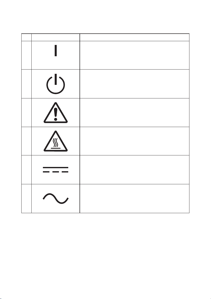
Description of Safety symbols displayed on the equipment
No. Symbol Description
1
"ON" (power)
To indicate connection to the mains, at least for
mains switches or their positions.
2
3
4
5
6
Stand-by
To identify the switch or switch position by means of
which part of the equipment is switched on in order
to bring it into the stand-by condition.
General warning/caution
To identify a general warning/caution.
Caution, hot surface
To indicate that the marked item can be hot and
should not be touched without taking care.
Direct current
To indicate on the rating plate that the equipment is
suitable for direct current only; to identify relevant
terminals.
Alternating current
To indicate on the rating plate that the equipment
is suitable for alternating current only; to identify
relevant terminals.
Page 5

Table of Contents
1. Appearance and Name of Components ············································· 5
1-1. Names of Components ······················································· 5
1-2. Package Contents ····························································· 6
2. AC Adapter ·············································································· 7
3. Paper Specifications ···································································· 8
3-1. Paper Width ··································································· 8
3-2. Paper Thickness ······························································ 8
3-3. Paper Roll ······································································ 8
3-4. Recommended Thermal Paper ············································ 9
4. Preparation ············································································ 10
4-1. Connecting the Interface Cable (to the printer) ····················· 11
4-2. Connecting the Interface Cable (to the PC)··························· 13
4-3. Connecting the Drawer Kick Cable ···································· 15
4-4. Connecting the AC Adapter and Cable ································ 16
4-5. Removing the AC Adapter ··············································· 19
4-6. Installing the Printer ······················································· 20
4-7. Power On ····································································· 24
4-8. Installing the Printer Software ·········································· 25
5. Inserting Paper ········································································ 26
5-1. Opening the Top Cover ··················································· 26
5-2. Paper Width Setting (Width: 58mm / 80mm) ························ 28
5-3. Setting the Paper ··························································· 30
5-4. Closing the Top Cover ····················································· 32
6. Control Panel ·········································································· 33
6-1. Control Panel ································································ 33
6-2. Error Indications ··························································· 34
7. Paper Jam Prevention and Removal ·············································· 36
7-1. Paper Jam Prevention ····················································· 36
7-2. Paper Jam Removal ························································ 36
7-3. If the Top Cover Does Not Open ········································ 37
8. Troubleshooting ······································································· 40
8-1. Problems at Power-on and Other Errors ····························· 40
8-2. Cutter Problems ···························································· 40
8-3. Printing Problems ·························································· 41
9. Special Mode (Test Print, Setup Menu...) ········································ 42
9-1. Test Print ····································································· 42
9-2. Changing the Setup ························································ 44
9-3. Setup Settings ······························································· 54
9-4. LAN Setup Settings (Printer with triple interface model) ········· 60
3
Page 6

9-5. HEX Dump·························································································63
9-6. Command Trace················································································64
9-7. Sample Print······················································································65
10. Regular Cleaning······························································································ 70
10-1. Cleaning Paper Holder and Paper Transport······························70
10-2. Cleaning the Platen Roller······························································71
10-3. Cleaning the Thermal Head···························································72
11. Interface ············································································································ 73
11-1. Serial Interface················································································73
11-2. USB Interface···················································································76
11-3. LAN Interface·················································································· 76
11-4. Drawer Kick Connector··································································77
11-5. Power Specifications········································································79
12. Specifications ····································································································80
12-1. General Specifications·····································································80
12-2. Cutter Specifications·······································································83
12-3. Paper Roll Supply Specifications···················································83
12-4. Interface Specifications···································································83
12-5. Environment Specifications····························································84
12-6. Reliability Specifications·································································85
13. Usage Precautions ···························································································· 86
13-1. Paper Related Precautions ·····························································86
13-2. Cutter Related Precautions····························································87
13-3. Barcode/2D Code Printing Precautions·········································87
13-4. USB Interface Usage Precautions··················································88
13-5. LAN Interface Usage Precautions··················································88
13-6. Installation Precautions··································································89
13-7. Modular Type Connector Usage Precautions·······························89
4
Page 7
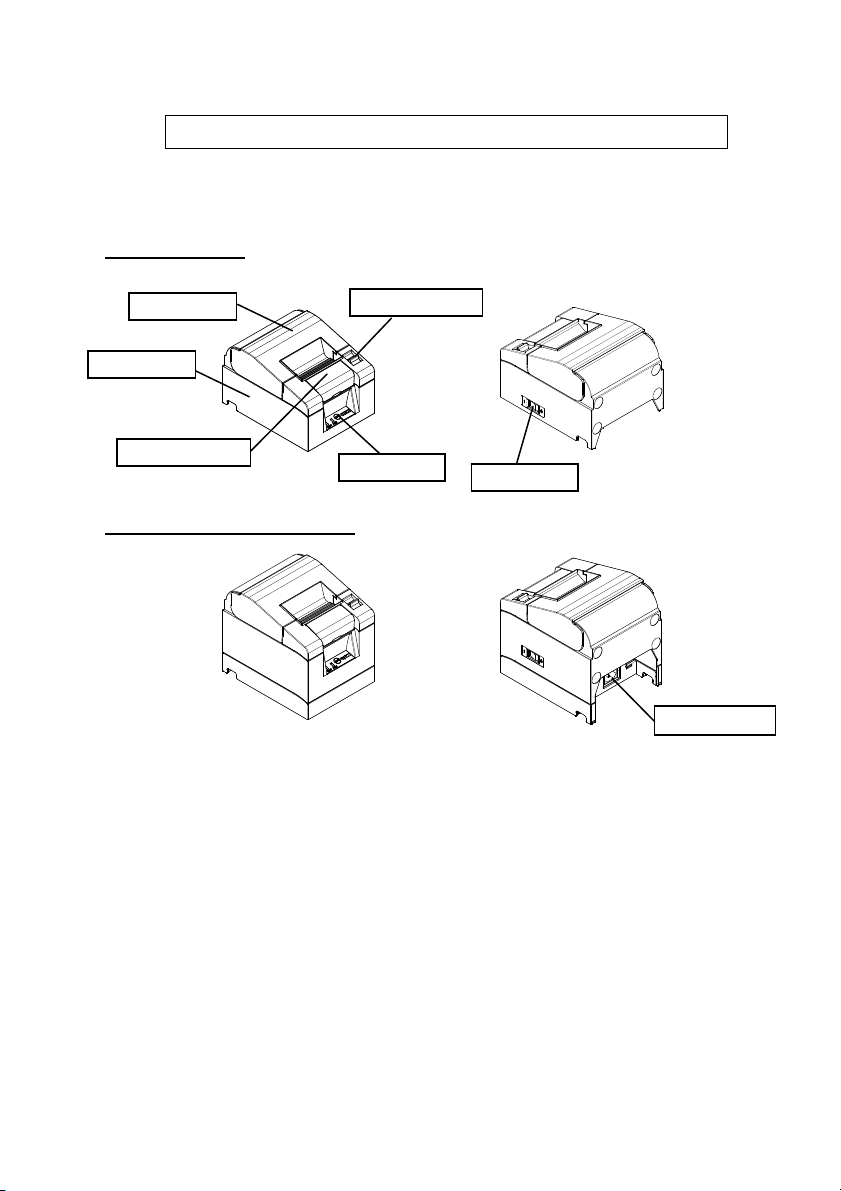
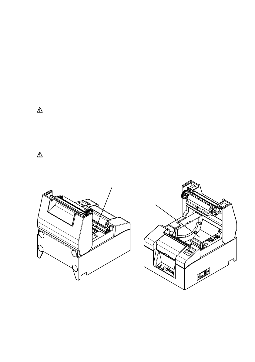
1. Appearance and Name of Components
1-1. Names of Components
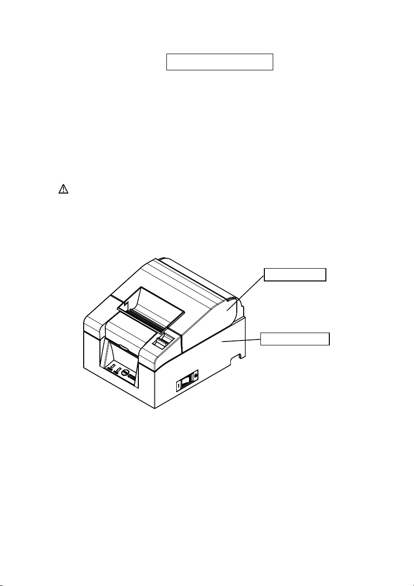
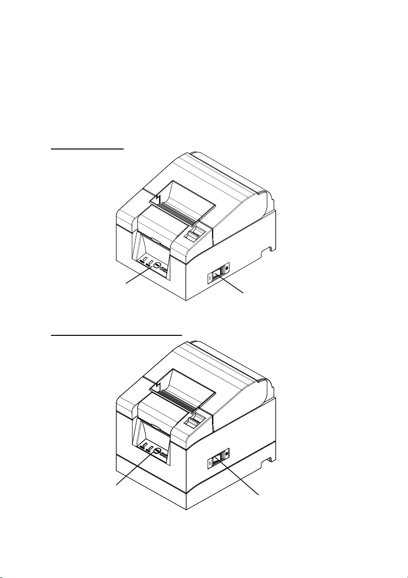
Standard Model
Top Cover
Middle Cover
Front Cover
Built-in Power Supply Model
• Top Cover
Open
• Release Lever
• Power Switch
• Control Panel
s to replace paper.
Used for opening the top cover.
Turns the printer power ON/OFF.
Contains switches for operating the printer and LEDs that indicate the printer
status.
• Front Cover
This can be removed in case of cutter jam or when the top cover does not open.
• AC Inlet
Plug in the AC power supply cable here.
Release Lever
Control Panel
Power Switch
5
AC Inlet
Page 8
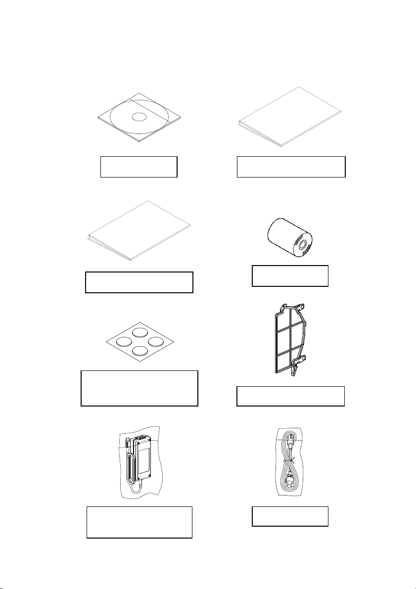
1-2. Package Contents
Safety warranty sheet
(For vertical installation)
CD Instruction sheet
Rubber Feet
AC Adapter
(Standard Model)
Thermal Paper
58mm Width Separator
Power cable
6
Page 9
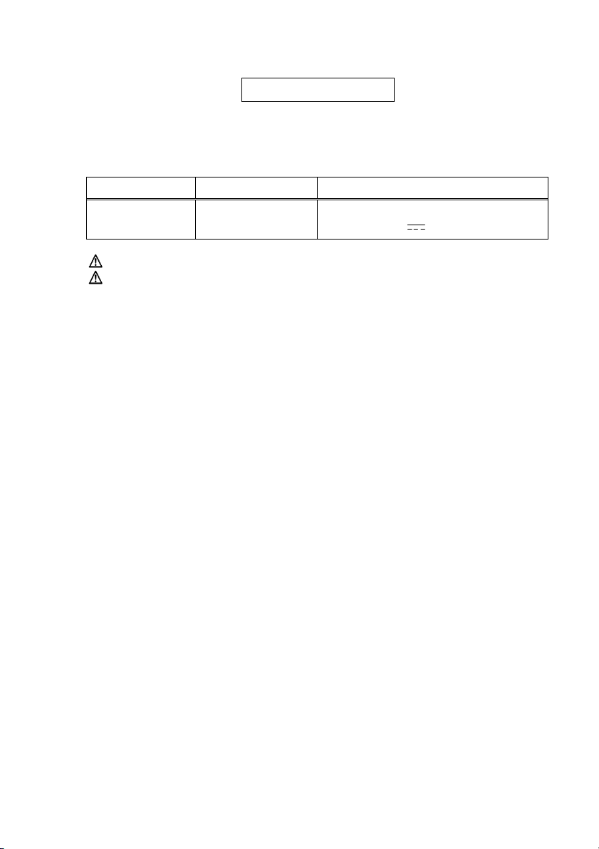
2. AC Adapter
Only use the AC adapter specified below.
Item No. Remarks
AC Adapter
Caution: Only use authorized AC adapters.
Caution: Do not use any other bundled AC adapter other than designed
KA02951-0120
for this printer.
Input : 100 to 240V AC, 50-60Hz
Output : 24V ±5%,1.5A
7
Page 10

3. Paper Specifications
Only use the thermal paper roll specified below.
3-1. Paper Width
• 80mm paper
• 58mm
paper
80mm
58mm
3-2. Paper Thickness
• 65 - 85μm
3-3. Paper Roll
• Outside diameter: φ83mm or less
• Core diameter: φ12±0.5mm (inside) / φ18±0.5mm (outside)
0
0.1
0
0.1
• Printing surface:
outer surface of the roll
• Treatment of end of paper: The roll paper must not be glued to the core.
The end of the paper must also not be folded
back.
Caution: Do not use rolls that have rough sides or sides from which
pieces of paper extrude. Such paper may cause unstable
paper feeding, resulting in printer trouble.
8
Page 11
3-4. Recommended Thermal Paper
Manufacturer Product
Name
Oji Paper Co.,
Ltd.
PD160R
PD190R
Nippon Paper
Industries
Co., Ltd.
TF60KS-E
TP60KS-F1
TF50KS-E
TF62KS-E
Caution: Using non-recommended paper may cause printer head
damage, bad printing quality, etc.
Quality Characteristic Paper
Monochrome thermal paper
(high-grade preservation type )
Monochrome thermal paper
(mid-grade preservation type )
Monochrome thermal paper
(normal type)
Monochrome thermal paper
(mid-grade preservation type)
Monochrome thermal paper
(normal type)
Monochrome thermal paper
(normal type)
Density
Thickness
75μm 100%
75μm 100%
75μm 100%
75μm 100%
65μm 100%
85μm 100%
9
Page 12
4. Preparation
No printer cable is provided with the product. Obtain a printer cable suitable for
the product interface. If you have any question, consult your dealer. Before
connecting or disconnecting cables, make sure of the following:
(1) The power to the printer and all other devices connected to the printer is
turned off.
(2) The AC adapter power cable has been unplugged from the outlet.
Caution: When connecting cables or moving the printer, hold the
middle part of the printer cover on both sides. Holding the top
cover may cause it to open.
Top Cover
Middle Cover
10
Page 13
4-1. Connecting the Interface Cable (to the printer)
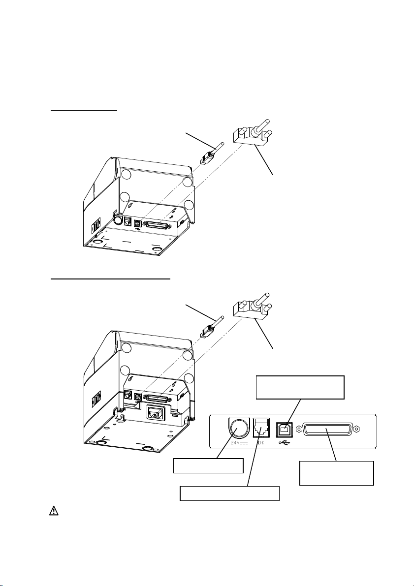
4-1-1 Printers with serial and USB interfaces
Standard Model
Built-in Power Supply Model
USB Interface Cable Type-B
* Connect the printer to a PC through this connector.
USB Interface Cable Type-B
* Connect the printer to a PC through this connector.
Power Connector
Drawer Kick Connector
Caution: Do not connect both the serial and USB interfaces at the same
time.
Serial Interface Cable
* Use the screws to secure it in place after connection.
Serial Interface Cable
* Use the screws to secure it in place after connection.
USB Interface
Type-B Connector
Serial Interface
Connector
11
Page 14
r
r
r
r
p
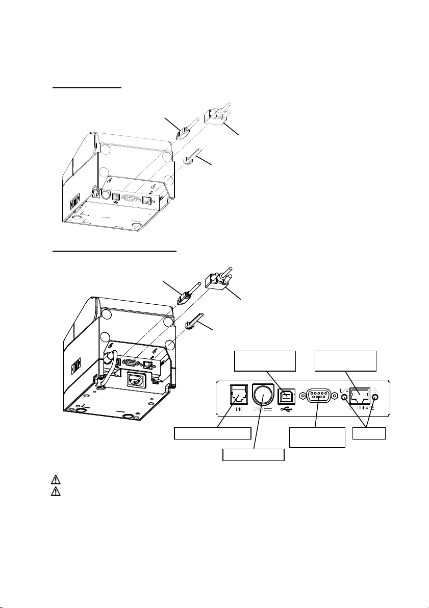
4-1-2 Printers with serial, USB and LAN interfaces
Standard Model
USB Interface Cable Type-B
* Connect the printer to a PC through this connector.
Serial Interface Cable
* Use the screws to secure it in place after connection.
LAN Interface Cable
Built-in Power Supply Model
USB Interface Cable Type-B
* Connect the
rinter to a PC through this connector.
Serial
Interface Cable
e the screws to secure it in place after connection.
* Us
LAN Interface Cable
USB Interface
Type-B Connecto
LAN Interface
Drawer Kick Connector
Power Connecto
Serial Interface
Connecto
Caution: Do not connect the multiple interfaces at the same time.
Caution: While this printer supports 3 different interfaces, it is set to LAN
Settings at time of shipment, so if you intend on using the USB or
serial interfaces, please make sure to change settings prior to use.
For more details on how to change setup se ttings, plea s e refe r to “9-4.
LAN Setup Settings".
Connecto
LED
12
Page 15

4-2. Connecting the Interface Cable (to the PC)
4-2-1 Serial Interface
(1) Connect the connector of serial interface cable to the serial port on the
computer as shown in the figure.
2 USB Interface
-
4-2
(1) Connect the connector of USB interface cable to the USB port on the
computer as shown in the figure.
13
Page 16

4-2-3 LAN Interface
(1) Connect the connector of LAN interface cable to the LAN port on the
computer as shown in the figure.
14
Page 17
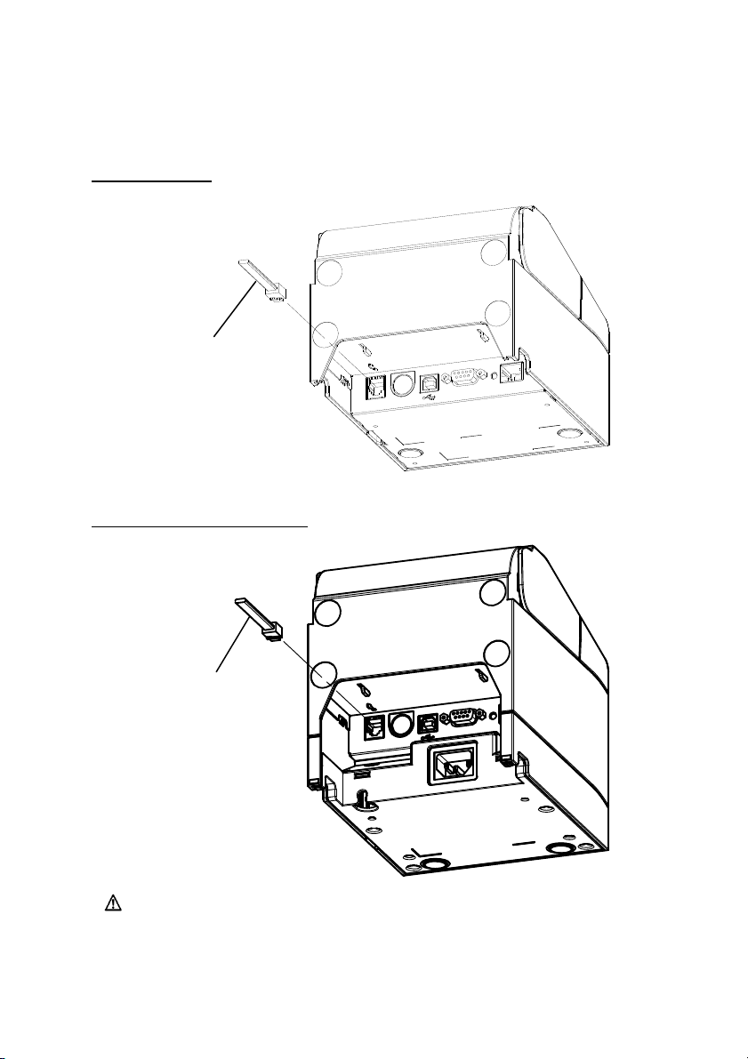
4-3. Connecting the Drawer Kick Cable
Standard Model
Drawer Kick Cable
Built-in Power Supply Model
Drawer Kick Cable
Caution: This product uses a special-purpose modular connector for the
cash drawer. Do not attempt to use other types of connectors
such as public telephone connectors.
15
Page 18
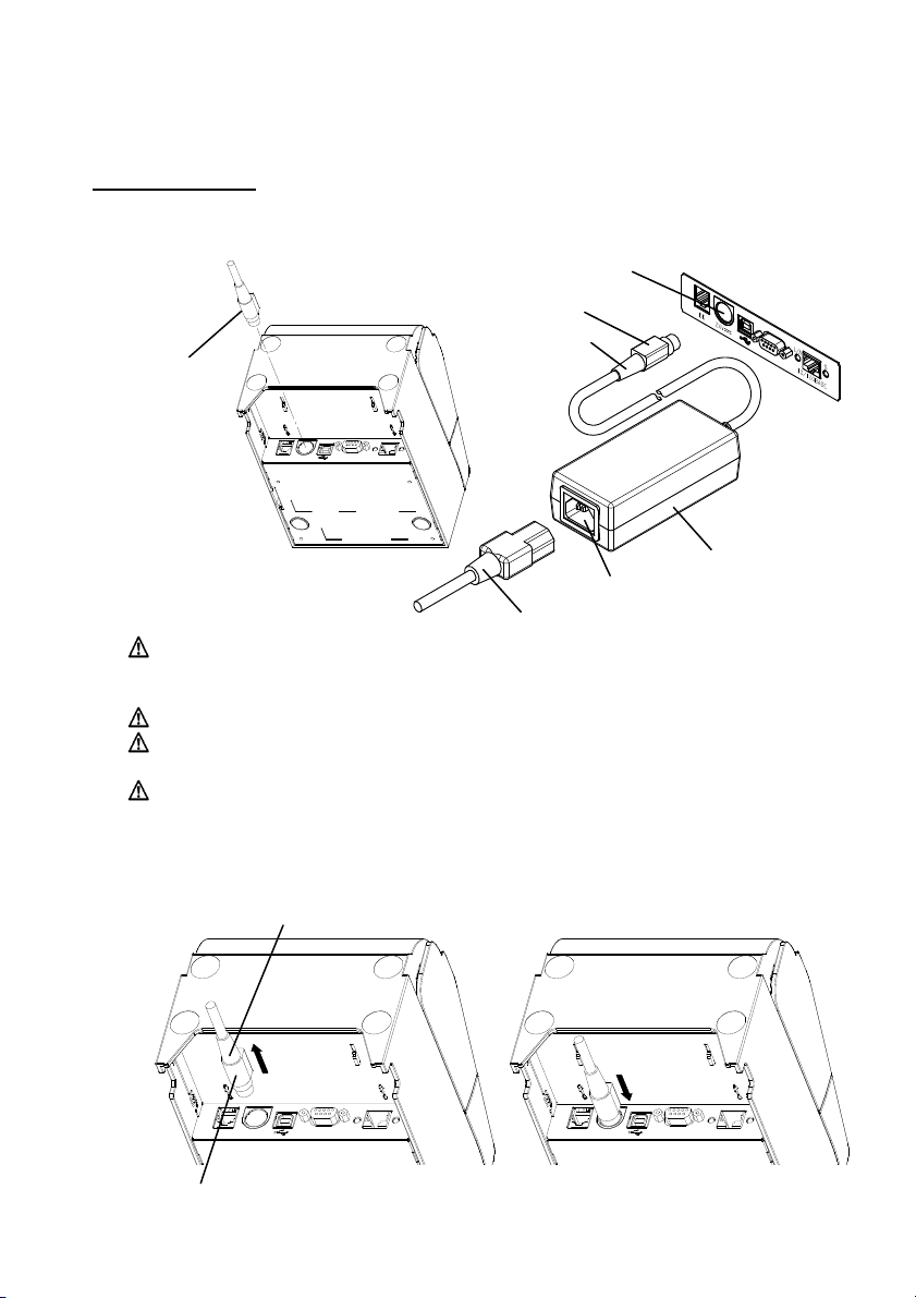
4-4. Connecting the AC Adapter and Cable
Standard Model
(1) Connect the cable connector of the AC adapter to the power connector.
AC Adapter
Connector
Caution: Before connecting the AC adapter, turn off the power switches
Caution: Use the specified AC adapters.
Caution: Perform the adapter connection with the device placed vertically
Caution: As the connector is clipped in place after insertion in order to
Th
e Outer Section of the Connector
Power Connector
Flat Side
Cable Connector
AC Adapter
AC Inlet
Power Cable
on the printer and all the devices connected to the printer. Also,
remove the plug of the AC adapter power cable from the outlet.
for easy operation.
prevent it from falling off, when performing insertion, (1) grip the
cable base with one hand, (2) slide the outer part of the
connector upwards with the other hand (3) and push in until it
locks into place.
Cable Base
(1)
(2)
16
(3)
Page 19
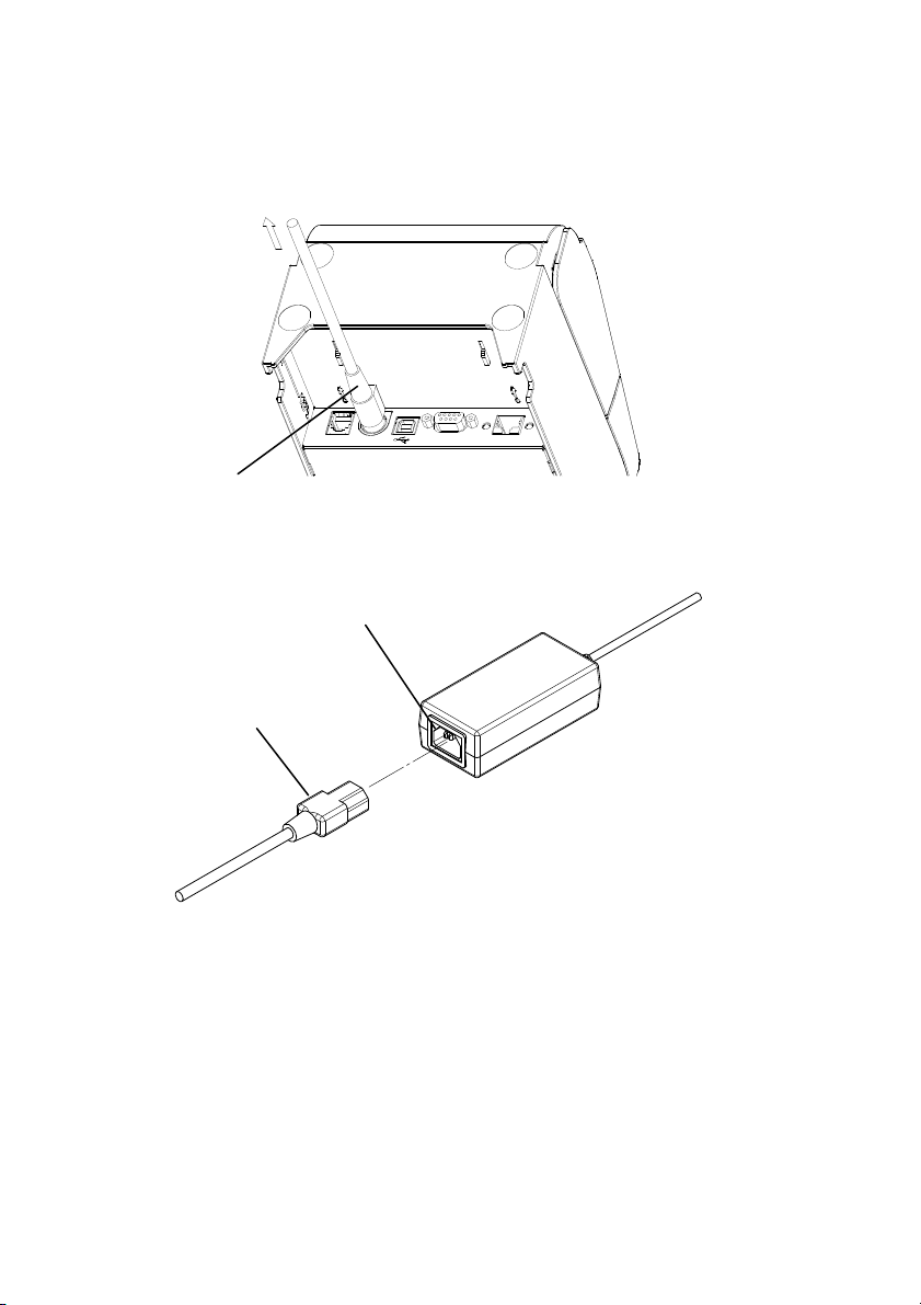
(2) Confirm that the cable is locked in place by gently pulling on the cable base
after connection.
Cable Base
Co
nnect the power connector to the AC inlet of the AC adapter.
(3)
The AC Inlet of the AC Adapter
Power Cable
sert the plug of the power cable into the outlet.
In
(4)
17
Page 20
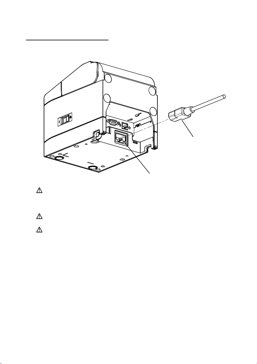
Built-in Power Supply Model
(1) Connect the power connector to the AC inlet.
Power Cable
Caution: Before connecting the power cable, turn off the power
switches on the printer and all the devices connected to the
printer. Also, remove the plug of the power cable from the
outlet.
Caution: Perform power cable connection with the device placed
vertically for easy operation.
Caution: If the device is installed vertically, use a right-angled power
cable.
AC Inlet
(2) Insert the plug of the power cable into the outlet.
18
Page 21
4-5. Removing the AC Adapter
To remove the cable of the AC adapter, pull it while gripping the connector
section on the cable side as shown in the following figure. The lock is
released, making it easy to remove. Forcibly pulling the cable will damage
the connector section.
The Cable Connector
Caution: Before removing the AC adapter, turn off the power switches
on the printer and all the devices connected to the printer. Also,
remove the plug of the AC adapter power cable from the outlet.
Caution: Perform adapter removal with th e d evice placed vertically for
easy operation.
19
Page 22
t
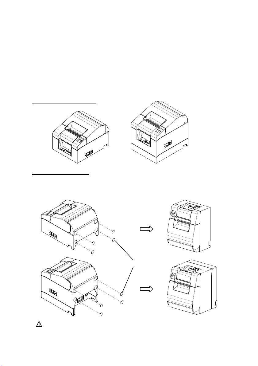
4-6. Installing the Printer
Both horizontal installation (the paper exit is on the topside) and vertical
installation (the paper exit is on the front side) orientations are available.
In the case of vertical installation, attaching the optional splash-proof cover can
protect the printer from water.
The printer can also be fixed to the wall by using the optional wall-hanging
bracket.
Horizontal Installation
Vertical Installation
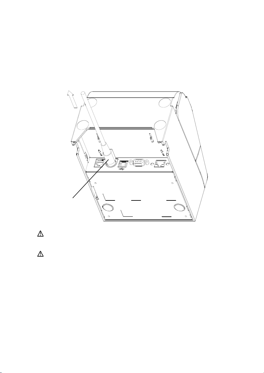
If the printer is installed vertically, stick the rubber feet (included in the package)
into the round indents on the printer rear cover.
Caution: Before sticking on the rubber feet, wipe off any dirt inside the
indents.
Rubber Fee
20
Page 23
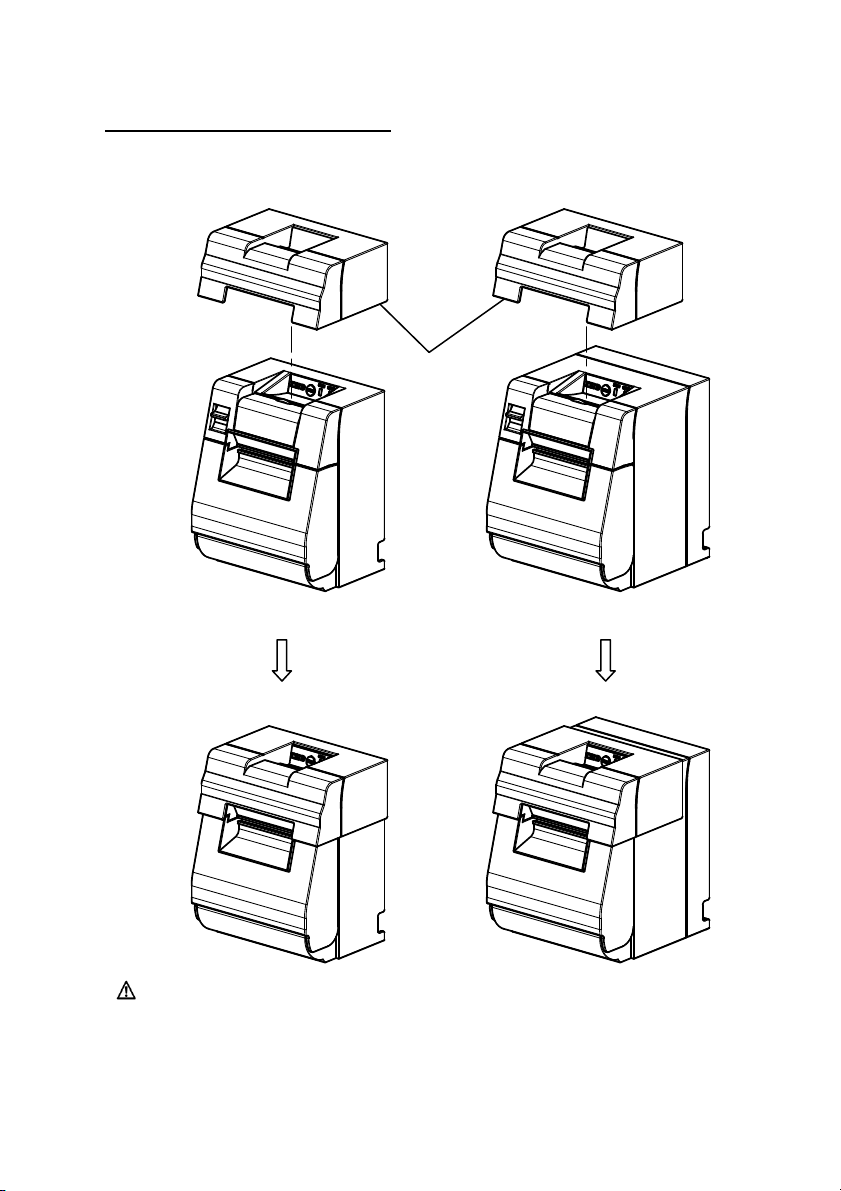
Splash-proof Cover (Optional)
Mount the splash-proof cover at the top when the printer is installed vertically.
Splash-proof Cover
Caution: The splash-proof cover is used only for vertical installation.
21
Page 24
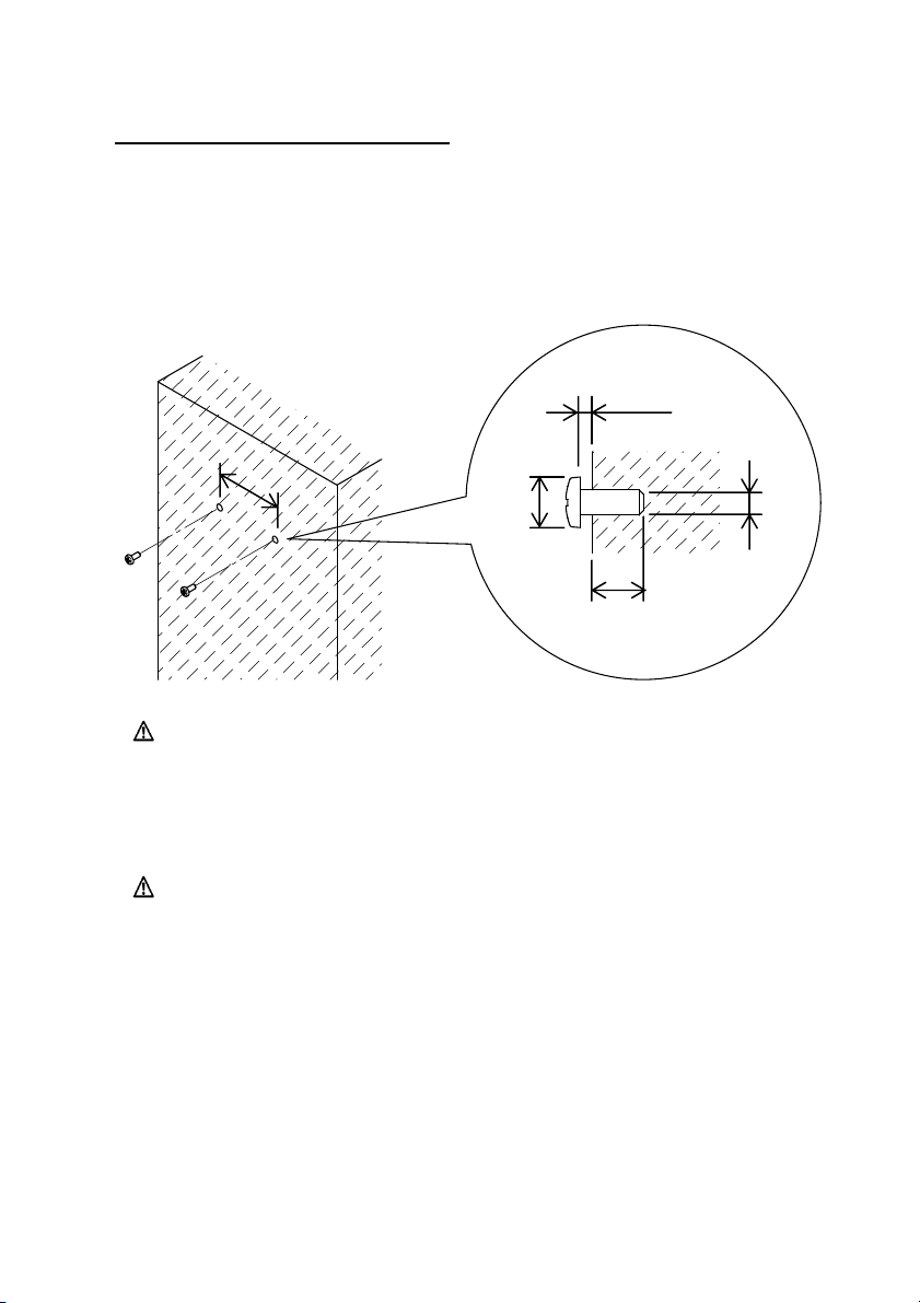
Wall Hanging Bracket (Optional)
To fix the printer to a wall, follow the procedures below:
(1) Mount two metal screws (thread diameter: Φ4, head diameter: Φ7) on the wall,
spaced 62mm apart in a horizontal line, such that the length of each screw
entering the wall is at least 10mm and the length protruding outside is 2-4mm.
2~4mm
62mm
7~9mm
4mm
More than or
equal to 10mm
Caution: In order to firmly fix the printer, mount the wall hanging bracket
onto a wooden, concrete or metal wall. It is recommended that the
wall thickness should be 10mm or more.
Use metal screws.
The screws mounted on the wall are required to have a pull-out
strength of 150N (15.3kgf) or more.
Caution: The wall hanging bracket can be used only for printers that use
an external AC adapter (Standard Model).
22
Page 25
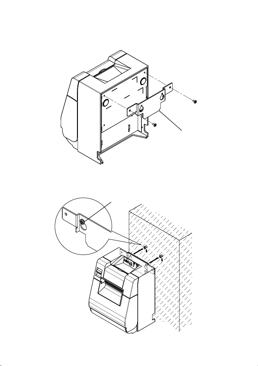
(2) Attach the wall hanging bracket to the printer and fix it securely with the
enclosed screws.
Wall Hanging Bracket
Align the holes of the wall hanging bracket with the screws mounted to the
)
(3
wall and hang the printer securely.
Screw Head Section
23
Page 26
4-7. Power On
(1) Connect to the power cable according to 4-4 above.
(2) Turn on the power switch at the side of the printer.
After turning the power on, the POWER LED on the control panel will light
up.
Standard Model
Control Panel
Built-in Power Supply Model
Control Panel
Power Switch
Power Switch
24
Page 27

4-8. Installing the Printer Software
Refer to the "Installation Guide"(*1) in the enclosed CD for instructions on
installing the printer driver and utility software.
*1: \Manuals\PT340-341_InstallGuide_en.pdf
The "Installation Guide" can also be viewed by loading the CD in your PC's
CD drive and selecting "Manuals" on the "Setup" screen that appears.
25
Page 28
5. Inserting Paper
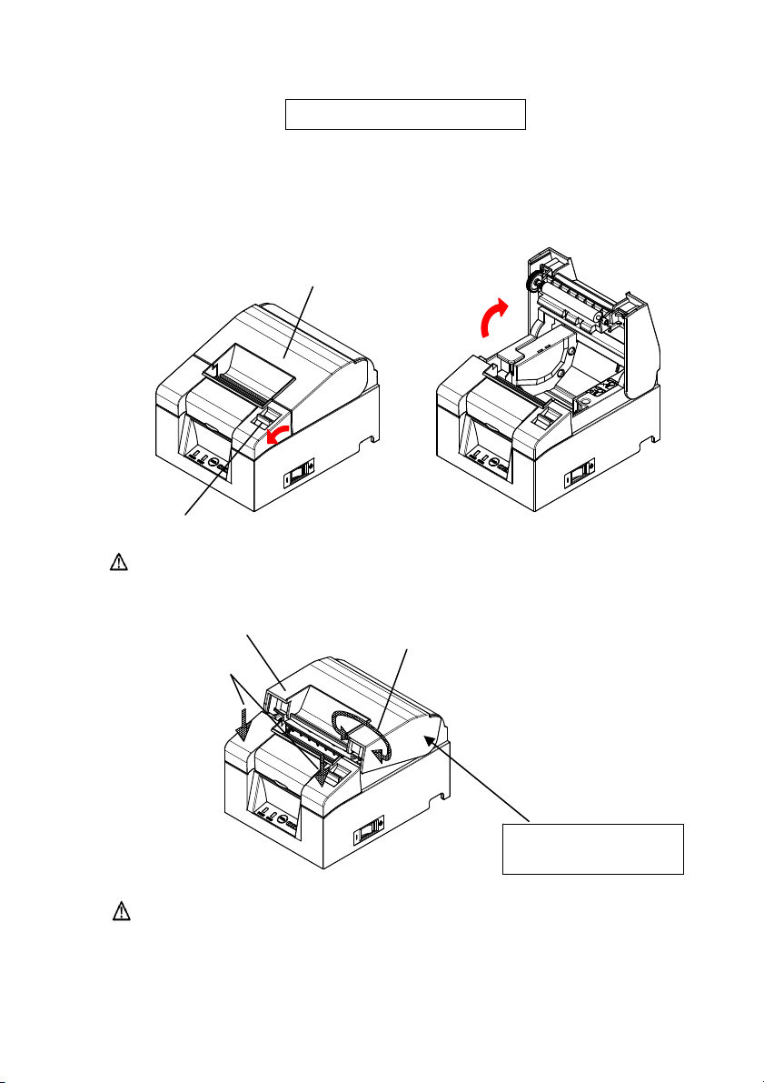
5-1. Opening the Top Cover
(1) Pull the release lever in the direction of the arrow, and then open the top
cover.
Release Lever
Caution: Lift the cover until it is vertical so that it will stay open.
Part C
Caution: To open the cover, use either side of part C to hold the
printer steady and use part A or part B to lift the cover. To
prevent your fingers being pinched, please do not touch the
area around the top cover hinge.
Top Cover
Part A
Part B
The fulcrum point
of top cover
26
Page 29
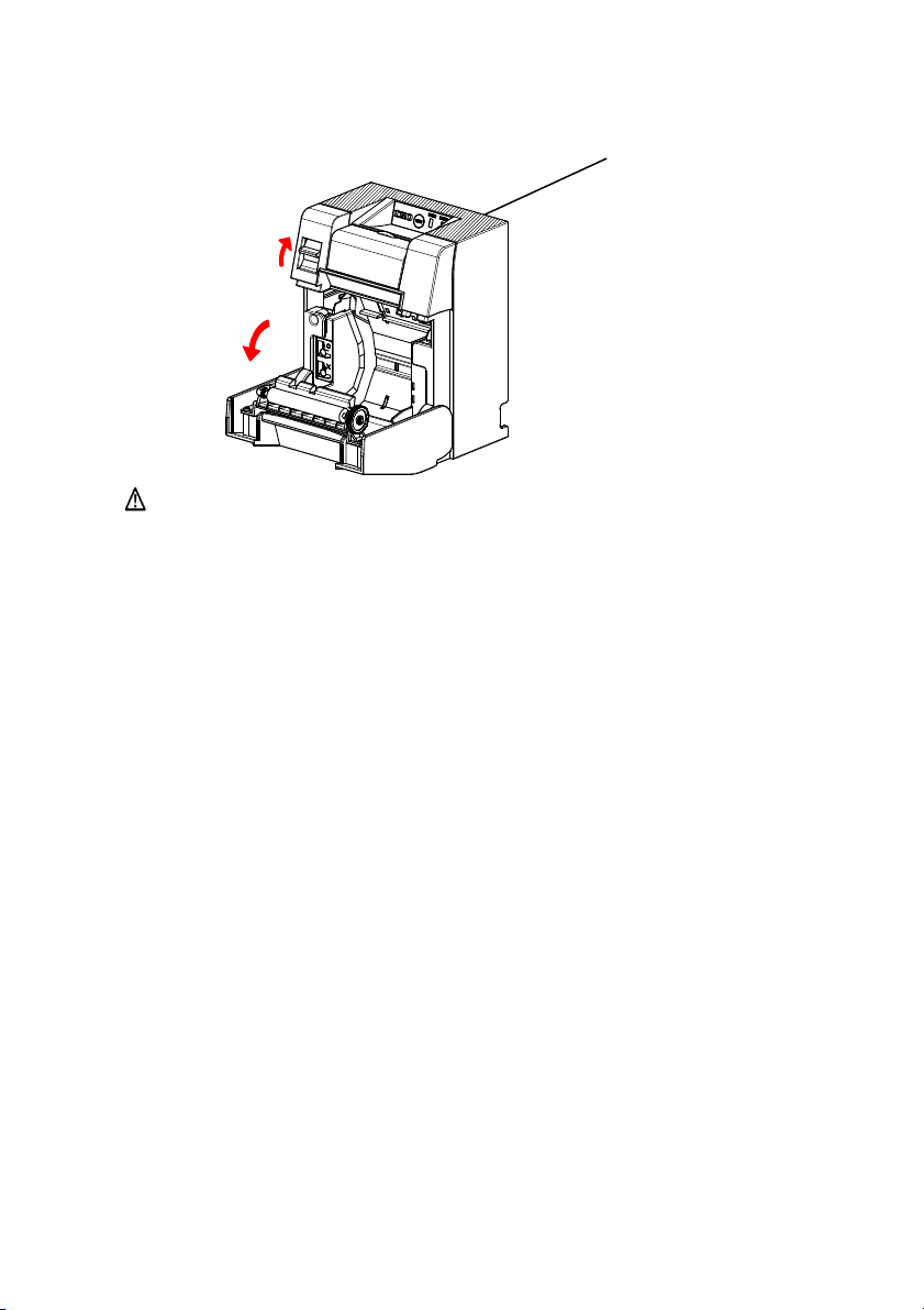
Front part of Printer
(Shaded part)
Caution: When using printer vertically, steady the front part of the printer
(shaded part in the above picture) to open the top cover.
27
Page 30
5-2. Paper Width Setting (Width: 58mm / 80mm)
As the factory setting for paper width is 80mm, follow the instructions in "5-3.
Setting the Paper" to set the paper roll when using 80mm paper.
When using 58mm paper, first attach the separator in accordance with the
instructions in "5-2-1. Attaching the Separator" and then set the paper roll.
Also, follow the instructions in "9-2. Changing the Setup" to set the "Paper
Width" in the printer setup to "58mm/35columns" or "58mm/32columns".
Caution: Do not switch from the 58mm width paper to 80mm width
paper when printing is in progress. When using narrow-width
paper, a part of the thermal head may directly come in contact
with the platen roller without any paper present. This causes
the head to wear down, resulting in poor printing quality.
In addition, as the cutter blade also works on sections without
paper, the cutter blade may wear down, resulting in a bad cut.
Caution: As the thermal head may be damaged by static electricity, do
not touch the thermal head except for cleaning.
Thermal Head
Roll Holder
28
Page 31

5-2-1 Attaching the Separator
(1) Align the three lugs of the supplied 58mm width separator with the
corresponding holes on the printer body, then push it into place.
58mm Width Separator
Setting Hole
Caution: Push the plate until it locks with a clicking sound and confirm
that the top side of the separator is horizontal.
Caution: When moving the separator follow the instructions in the
Special Mode section to set the paper width and align it with
the printing area.
(Refer to 9 Special Mode: 9-2. Changing the Setup.)
29
Page 32

5-3. Setting the Paper
(1) In the case of a new roll of paper, remove the glued portion and tape on the
paper roll.
When replacing the roll paper, first remove the old paper core.
Caution: Since the glued portion of the paper should not be printed on,
remove about one turn (about 30 cm) of the roll paper from the
beginning so that none of the remaining paper has glue on it.
Any adhesive or other matter remaining from the glue may
adhere to the thermal head and cause a problem, such as
voids on printouts. Therefore, do not forget to remove the
glued portion of the paper.
(2) After inserting the new roll of paper with the orientation shown, pull the end
of the paper in the direction indicated by the arrow [1].
Top of Cover
Caution: Pull the end of the paper so that it passes over the top of the
cover.
Caution: Do not damage or dent the platen roller.
Dents on the platen roller will cause gaps in the printing
and/or line feed failure.
Platen Roller
[1]
30
Page 33

Caution: Setting the paper as shown in the following figures may cause
paper or printing jams.
The paper does not pass over
the top of the cover.
The paper has been set incorrectly.
Caution: Do not use deformed roll paper. Using rolls such as those
shown below may cause trouble such as paper or printing
jams.
Caution: If the roll paper is loose (slack) as shown b elow, remove the
slack before using the roll. Using without removing the slack
may cause paper or printing jams, or result in failure to detect
the paper near end condition.
31
Page 34

5-4. Closing the Top Cover
Set the paper correctly and carefully close the top cover.
Caution: Set the paper correctly. Closing the top cover while the paper
is skewed may cause a paper jam or messy printing.
Caution: When clo sing the top cover, close it securely by pressing
around the central position (shown by the arrow in the figure)
until you hear a clicking sound. If the cover has not locked
into place, the printer may not function.
Caution: When the printer is mounted vertically, use the front of the
printer (shaded part in the above picture) to hold it steady when
opening the top cover.
Push
Top Cover
Front part of Printer
(Shaded part)
32
Page 35

6. Control Panel
6-1. Control Panel
)
POWER LE
If the power switch is turned on and the printer is supplied with power, this
LED will light up.
ERROR LED()
This LED lights up or blinks to indicate an error.
FEED Button
Pressing this button once causes the printer to feed the paper by an amount
equivalent to one line.
Holding it down feeds the paper continuously.
Caution: When the printer is mounted vertically, always hold the rear of
D(
the printer when you press the FEED button to keep the printer
steady and prevent it from falling over.
Rear of the Printer
33
Page 36
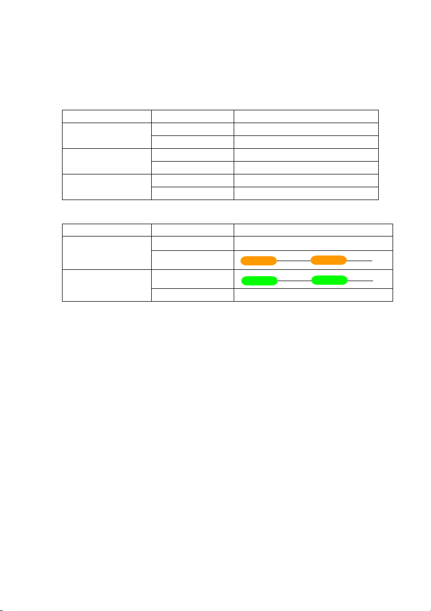
6-2. Error Indications
Recoverable errors
Error State LED Lamp Blinking Pattern
No paper
Paper end
Error State LED Lamp Blinking Pattern
Paper near end
Head hot
POWER () Constantly on
ERROR () Constantly on
POWER () Constantly on Cover open
ERROR () Constantly on
POWER () Constantly on Cutter jam
ERROR () Constantly on
POWER () Constantly on
ERROR ()
POWER ()
ERROR ()
Remains unchanged.
34
Page 37

Unrecoverable errors
Error State LED Lamp Blinking Pattern
Internal error
Head not
installed
Low voltage
Over voltage
Watchdog timer
error
SPI Flash ROM
error
POWER()
ERROR()
POWER()
ERROR()
POWER()
ERROR()
POWER()
ERROR()
POWER()
ERROR()
POWER()
ERROR()
————
—————
Repetition of two blinks of the lamp
and one blink of the lamp
—————
———————
Repetition of three blinks of the lamp
and one blink of the lamp
——————
——————————
Repetition of four blinks of the lamp
and one blink of the lamp
———————
————————————
Repetition of five blinks of the lamp
and one blink of the lamp
——————————
——————————————————
Repetition of eight blinks of the lamp
and one blink of the lamp
—————————
——
———————————————
———
Repetition of nine blinks of the lamp
and one blink of the lamp
35
Page 38

7. Paper Jam Prevention and Removal
7-1. Paper Jam Prevention
Do not touch the paper while it is coming out or before cutting is complete.
Pressing or pulling the paper with your hand while it is coming out may cause
a paper jam, bad cut, or bad line feed.
7-2. Paper Jam Removal
In case of a paper jam, remove the paper as follows:
(1) Turn off the power switch to disconnect the printer from the power.
(2) Pull the release lever towards you, and then open the top cover.
If the top cover does not open, refer to the instructions in "7-3. If the Top
Cover Does Not Open" to remove the cutter jam.
(3) Press the printer and remove the jammed paper.
Caution: When removing paper, remove the paper slowly without
pulling it forcibly.
Caution: As the thermal head may be damaged by static electricity, do
not touch the thermal head. Also, do not touch the thermal
head as it may still be hot after printing.
(4) Set the paper correctly and carefully close the top cover.
Caution: Set the paper correctly. Closing the top cover while the paper
is skewed may cause a paper jam or messy printing.
Caution: When closing the top cover, close it securely by pressing
around the central position until you hear a clicking sound. If
the cover has not locked into place, the printer may not
function.
(5) Turn on the power switch . Also, at this time confirm that the ERROR
lamp has turned off.
Caution: As printing data cannot be received while the ERROR lamp is
on, firmly close the top cover.
36
Page 39

7-3. If the Top Cover Does Not Open
When the printer has stopped with the cutter blade exposed due to some
abnormality such as a paper jam, the top cover will not open.
In such a case, instead of opening it forcibly, perform the following steps:
(1) Turn off the power switch to disconnect the printer from the power.
(2) Turn the power on again. This causes the cutter to operate and may clear
the paper jam.
(3) Pull the release lever toward you to check whether the top cover opens. If
so, turn the power off again and follow the instructions from step (6) to
clear the paper jam.
If the top cover still cannot be opened after the power is turned on, turn the
power off again and follow the instructions from step (4) to clear the paper
jam.
(4) Remove the front cover by lifting it as shown by the arrow.
Top Cover
Front Cover
37
Page 40

(5) Lift the protective sheet as indicated by arrow A and rotate the cutter gear
in the direction indicated by arrow B while pulling the release lever
toward you.
If the auto-cutter blade fails to move despite rotating the cutter gear and
the top cover still will not open, pull the release lever toward you and
rotate the cutter gear in the opposite direction (indicated by arrow C) until
the top cover is able to open.
Protective Sheet
Top Cover
A
B
Cutter Gear
C
Cutter Motor
Release Lever
Auto-cutter blade is
protruding
Top cover cannot open
Auto-cutter blade is
retracted
Top cover can open
Caution: Do not the touch the cutter motor, as it may still be hot after
printing.
Caution: Do not touch the auto cutter, as its blade end is sharp an d
dangerous.
Caution: When you cannot open Top Cover with rotating Cutter Gear to
either direction, call your service provider.
38
Page 41

(6) Open the top cover and remove the jammed paper while holding the
printer steady.
Caution: When removing paper, remove the paper slowly without
pulling it forcibly.
Caution: As the thermal head may be damaged by static electricity, do
not touch the thermal head. Also, do not touch the thermal
head as it may still be hot after printing.
(7) Set the paper correctly and carefully close the top cover.
Caution: Set the paper correctly. Closing the top cover while the paper
is skewed may cause a paper jam or messy printing.
Caution: When closing the top cover, close it securely by pressing
around the central position until you hear a clicking sound. If
the cover has not locked into place, the printer may not
function.
(8) Turn on the power switch. Also, at this time confirm that the ERROR lamp
has turned off.
Caution: As printing data cannot be received while the ERROR lamp is
on, firmly close the top cover.
39
Page 42

8. Troubleshooting
This section provides solutions for printer malfunctions and print quality
problems.
8-1. Problems at Power-on and Other Errors
Symptom Cause Solution
Although the power has
been turned on, the
POWER lamp on the
control panel does not
light up and the printer
does not start.
The ERROR lamp on the
control panel lights up
and the printer does not
work.
8-2. Cutter Problems
Symptom Cause Solution
The paper is not cut. (1) The cutter blade is
The cutter does not return
to its correct position.
(1) The power cable is
disconnected.
(2) The AC adapter is not
plugged in.
(1) There is no paper in the
printer .
(2) The top cover is not
completely closed.
(3) The thermal head is
excessively hot.
damaged or worn out.
(2) Paper fragments or other
foreign matter are stuck
around the cutter or the
sliding section.
Paper fragments or other
foreign matter are stuck
around the cutter or the
sliding section.
(1) Connect the power cable.
* Refer to 4-4. Connecting the AC
Adapter and Cable.
(2) Connect the connector of the AC
adapter.
* Refer to 4-4. Connecting the AC
Adapter and Cable.
(1) Set the paper.
* Refer to 5. Inserting Paper.
(2) Close the top cover completely.
* Refer to 5. Inserting Paper.
(3) Wait for the thermal head to cool
down.
(1) Turn off the power and request
repair.
(2) Remove the paper fragments or
other foreign matter.
Remove the paper fragments or other
foreign matter.
40
Page 43

8-3. Printing Problems
Symptom Cause Solution
The printer does not
print.
Print is too dark or
blurred.
Print is too faint.
Printing is uneven.
Vertical marks
appear on the
printout.
(1) The interface cable is
disconnected or broken.
(2) The printer setup is not correct.
(1) Print density setting in the
printer setup is incorrect.
(2) The thermal head is damaged.
(1) Print density setting in the
printer setup is incorrect.
(2) The thermal head is damaged.
(1) Paper fragments or other
foreign matter are stuck to the
heating elements of the thermal
head.
(2) The setting of the printer setup
is incorrect.
(3) Foreign matter is stuck on the
platen roller.
(4) The thermal head is damaged.
(1) Foreign matter is stuck in or
dropped into the paper
transport.
(2) Foreign matter is stuck on the
thermal head.
(3) The thermal head is damaged.
(1) Connect the interface cable
correctly, or replace it.
* Refer to 4-1. Connecting the
Interface Cable
(2) Amend the setting.
Example: Baud rate mismatch
* Refer to 9-2,9-4. Changing the
Setup.
(1) Set the printer at the suitable print
density and/or print speed for the
print paper.
* Refer to 9-2. Changing the Setup.
(2) Turn off the power and request
repair.
(1) Set the printer at the suitable print
density and/or print speed for the
print paper.
* Refer to 9-2. Changing the Setup.
(2) Turn off the power and request
repair.
(1) Check and clean the thermal head.
* Refer to 10-3. Cleaning the
Thermal Head
(2) Set the printer at the suitable print
density and/or print speed for the
print paper. Amend the setting.
* Refer to 9-2. Changing the Setup.
(3) Remove the foreign matter from
the platen roller.
* Refer to 10-2. Cleaning the Platen
Roller
(4) Turn off the power and request
repair.
(1) Clean the paper transport.
* Refer to 10-1. Cleaning Paper
Holder and Paper transport
(2) Clean the thermal head.
* Refer to 10-3. Cleaning the
Thermal Head
(3) Turn off the power and request
repair.
41
Page 44

9. Special Mode (Test Print, Setup Menu...)
9-1. Test Print
Ensure that paper is set in the printer. Turn off the power switch on the printer,
then turn it on again while pressing the FEED button on the control panel. This
outputs the following printout.
Caution: Press and hold the FEED button until the printer starts
printing.
Special Mode
1.Test Print
2.Setup Menu
3.Hex Dump
4.Command Trace
5.Sample Print
6.End
<Set>
Press FEED button for the number of times
as the same as your selecting item, and
wait more than 1 second.
Dual interface model Triple interface model
Then Press the FEED button once (select 1. Test Print) to start a test print.
The printer automatically cuts the paper and stops after performing a set amount
of printing. To terminate the test print while in progress, press the FEED button.
This cuts the paper and terminates printing.
Paper feed direction
Special Mode
1.Test Print
2.Setup Menu
3.LAN Setup Menu
4.Hex Dump
5.Command Trace
6.Sample Print
用紙送り方向
7.End
<Set>
Press FEED button for the number of times
as the same as your selecting item, and
wait more than 1 second.
Paper feed
用紙送り方向
42
Page 45

Test Print (Example)
The Firmware Number and Firmware Version vary according to the model.
“123456”is an example serial number.
PT340-341 Ver1.0
123456
Memory Switch 1
Power On Status Enable
Receive Buffer 4KByte
Busy Condition Bufferfull
Receive Error ? Print
Auto LF Disable
DSR(#6)Reset Disable
INIT(#25)Reset Disable
USB Soft Reset Enable
Memory Switch 2
Cover Open Error Auto Recovery
Error Auto Recovery
Batch (COM IF) Enable
Batch (Other IF) Disable
Serial Number D isable
ASB Enable
Font-B Mode1
Print
Paper Width 80mm/48columns
Max Speed 220mm/s
Print Density 1 00%
Hardware
Error Alert None
Buzzer Interval Pattern 2
Buzzer Repetition Three
Graph/User NV-MEM 384KB/192KB
Cut at CoverClose Disable
PNE Detect Enable
Interface
Baudrate 115200BPS
Format 8NONE1
Protocol DSR/DTR
USB Printer
!"#$%&'()*+,-./0 1234
56789:;<=>?@ABCDEFG HI
JKLMNOPQRSTUVWXYZ[\ ]^
_~abcdefghIjklmnopq rs
∬
Dual interface model
∬
Paper feed direction
用紙送り方向
PT340-341 Ver2.0
123456
Memory Switch 1
Power On Status Enable
Receive Buffer 4KByte
Busy Condition Bufferfull
Receive Error ?Print
Auto LF Disable
DSR(#6)Reset Disable
USB Soft Reset Enable
Memory Switch 2
Cover Open Error Auto Recovery
Error Auto Recovery
Batch (COM IF) Enable
Batch (Other IF) Disable
Serial Number Disable
ASB Enable
Font-B Mode1
Print
Paper Width 80mm/48columns
Max Speed 220mm/s
Print Density 100%
Hardware
Error Alert None
Buzzer Interval Pattern 2
Buzzer Repetition Three
Graph/User NV-MEM 384KB/192KB
Cut at CoverClose Disable
PNE Detect Enable
Interface
Baudrate 115200BPS
Format 8NONE1
Protocol DSR/DTR
USB Printer
LAN Enable
Mac Address [xx:xx:xx:xx:xx:xx]
root Password "*******"
Printer Name "PT340-341"
DHCP Enable
IP Address 192.168. 1. 1
Subnet Mask 255.255.255. 0
Default Gateway 0. 0. 0. 0
SNMP
Authentic Community "***************"
Trap Community "public"
Trap Address(IP) 0. 0. 0. 0
SysContact ""
SysName ""
SysLocation ""
EnableAuthenTrap Disable(2)
!"#$%&'()*+,- ./012 34
56789:;<=>?@ABCDEFGHI
JKLMNOPQRSTUVWXYZ[\]^
_~abcdefghIjklmnopqrs
∬
用紙送り方向
∬
43
Triple interface model
Page 46

9-2. Changing the Setup
This section explains how to setup the printer without using a PC.
Alternatively, when the printer is connected to a Windows PC, the settings can
be changed using the utility software on the enclosed CD.
For instructions on installing and using the utility software, refer to the
"Installation Guide" and "Utility User's Guide" located in the Manuals folder
of the CD.
• Installation Guide : PT340-341_InstallGuide_en.pdf
• Utility User's Guide : PT340-341_UtilityGuide_en.pdf
The "Installation Guide" and "Utility User's Guide" can also be viewed by
loading the CD in your PC’s CD drive and selecting "Manuals" on the "Setup"
screen that appears.
Setting Example Select a higher print density
Print Density Changed from 100% to 130%
Perform setup as follows:
1. Check the printer state prior to setting.
(1) The power is off.
(2) The paper roll is set.
(3) The cover is closed.
44
Page 47

2. Ensure that paper is set in the printer. Turn off the power switch on the printer, then
turn it on again while pressing the FEED button on the control panel. This outputs
the printout shown in section 9-1.
Then Press the FEED button twice (to select 2. Setup Menu) enters setup
mode and prints the following menu.
Setup Menu
1.Setting
2.Setup Print
3.Save & End
4.Default Set
<Set>
Press FEED button for the number of times
as the same as your selecting item, and
wait more than 1 second.
<Return>
Continue to press FEED button more than
1 second.
Paper feed direction
用紙送り方向
45
Page 48

3. Then Press the FEED button once (to select 1. Setting) enters setting
mode and prints the following setting groups.
Setting
1.Memory Switch 1
2.Memory Switch 2
3.Print
4.Hardware
5.Interface
<Set>
Press FEED button for the number of times
as the same as your selecting item, and
wait more than 1 second.
<Return>
Continue to press FEED button more than
1 second.
Paper feed direction
用紙送り方向
46
Page 49

4. Then Press the FEED button three times (to select 3. Print) selects the
Print group and prints the following setting options.
Print
1.Paper Width 80mm/48columns
2.Max Speed 220mm/s
3.Print Density 100%
<Set>
Press FEED button for the number of times
as the same as your selecting item, and
wait more than 1 second.
<Return>
Continue to press FEED button more than
1 second.
<Setup Menu>
Continue to press FEED button more than
3 seconds.
Paper feed direction
用紙送り方向
47
Page 50

5. Then Press the FEED button three times (select 3.Print Density) selects
the Print Density setting and prints the following Print Density settings.
Print Density 100%
1.70%
2.80%
3.90%
4.100%
5.110%
6.120%
7.130%
<Set>
Press FEED button for the number of times
as the same as your selecting item, and
wait more than 1 second.
<Return>
Continue to press FEED button more than
1 second.
<Setup Menu>
Continue to press FEED button more than
3 seconds.
Paper feed direction
用紙送り方向
48
Page 51

6. Then Press the FEED button seven times (to select 7. 130%) returns to
the Print settings group.
Changed items are displayed in bold and underlined.
Print
1.Paper Width 80mm/48columns
2.Max Speed 220mm/s
3.Print Density 130%
<Set>
Press FEED button for the number of times
as the same as your selecting item, and
wait more than 1 second.
<Return>
Continue to press FEED button more than
1 second.
<Setup Menu>
Continue to press FEED button more than
3 seconds.
it t
To ex
o the previous level (<Return>)
⇒ Go to Section 7-1
To exit directly to the setup menu (<Setup Menu>)
⇒ Go to Ssection 7-2
Paper feed direction
用紙送り方向
49
Page 52

7-1. Exiting to Previous Level
Hold the FEED button down for 1 second or more until the buzzer
sounds twice.
Release the FEED button after the buzzer sounds.
This returns to the previous level and prints the Setting group
options.
Setting
1.Memory Switch 1
2.Memory Switch 2
3.Print
4.Hardware
5.Interface
<Set>
Press FEED button for the number of times
as the same as your selecting item, and
wait more than 1 second.
<Return>
Continue to press FEED button more than
1 second.
Paper feed direction
用紙送り方向
50
Page 53

Hold down the FEED button again for 1 second or longer until the
buzzer sounds twice. Release the FEED button after the buzzer
sounds.
This returns to the previous level and prints the Setup Menu.
Setup Menu
1.Setting
2.Setup Print
3.Save & End
4.Default Set
Paper feed direction
Proceed to step
<Set>
Press FEED button for the number of times
as the same as your selecting item, and
wait more than 1 second.
<Return>
Continue to press FEED button more than
1 second.
8.
用紙送り方向
51
Page 54

7-2. Exiting Directly to Setup Menu
Hold the FEED button down for 3 seconds or more to return to the Setup
Menu.
Although holding down the FEED button for a long time causes the buzzer
to sound twice after 1 second, ignore this and continue to press the FEED
button.
After about 3 seconds, the buzzer sounds three times and the following
menu is printed.
Setup Menu
1.Setting
2.Setup Print
3.Save & End
4.Default Set
Paper feed direction
Proceed to step
<Set>
Press FEED button for the number of times
as the same as your selecting item, and
wait more than 1 second.
<Return>
Continue to press FEED button more than
1 second.
8.
52
用紙送り方向
Page 55

8. Pressing the FEED button three times (to select 3. Save & End) saves the
settings, cuts the paper, and then exits setup mode.
Caution: If the power switch of the printer is turned off without
selecting "Save & End", any changes made will not be saved.
Checking the Settings
To check that the settings have been applied, follow the instru ctions in
section 9.1 to perform a test print.
The test print includes a list of printer settings. Use this to
confirm your changes.
53
Page 56

9-3. Setup Settings
Setting Groups
Settings Group Description
1
Memory Switch 1
2
Memory Switch 2
3 Print
4 Hardware
5 Interface Serial and USB interface settings
Setting Items and Detailed Setting Items
(Note) Setup items and the default values depend on the printer model and/or area.
(1) Memory Switch 1 Group
Item Description Setting Value
1
Power On Status
2
Receive Buffer
3 Busy Condition
4 Receive Error
5 Auto LF
6 DSR(#6)Reset
INIT(#25)Reset
7
*1
Memory Switch 1 settings
Memory Switch 2 settings
Print settings
Hardware settings
(This group is not displayed on printers with a LAN interface.)
Specifies Power ON notification.
Specifies receiver buffer size.
Sets the printer as BUSY (data
reception not available).
Specifies what to do when a receive
error occurs using the serial interface.
Specifies whether the CR code
generates an automatic line feed.
Specifies whether receiving DSR
(#6) via the serial interface triggers a
hardware reset.
Specifies whether receiving INIT
(#25) via the serial interface triggers
a hardware reset.
Enable
1
Disable
2
1245bytes
4Kbytes
12Buffer full
Offline/Buffer full
12?Print
Ignore
12Enable
Disable
12Enable
Disable
12Enable
Disable
54
Page 57

Item Description Setting Value
Specifies whether a USB Soft Reset
8 USB Soft Reset
triggers a hardware reset when using
printer class USB.
*1 " INIT(#25)Reset "
Only Dual interface model.
(2) Memory Switch 2 Group
Item Description Setting Value
1
Cover Open Error
2
Error
3 Batch (COM IF)
4 Batch (Other IF)
5 Serial Number
6 ASB
7 Font-B
Recovery method for Cover Open Error
during print
What to do at power on or after recovery
from error
"Auto Recovery": Perform auto recovery
to enable data reception.
"Recovery by CMND": Discard any
received data until a reset command is
received.
Specifies whether to use batch printing
for the serial interface
Specifies whether to use batch printing
for the USB or LAN interface
Specifies iSerial Number notification for
USB
"Disable": Returns “0” as the iSerial
"Enable": Returns the manufacturing
Specifies whether to enable the automatic
status transmission function
(ASB: Automatic Status Back)
Specifies the number of columns for font
B (horizontal x vertical)
"Mode1" 10x24
"Mode2" 9x24
Number.
serial number as the iSerial
Number
12Enable
Disable
Auto Recovery
1
Recovery by CMND
2
12Auto Recovery
Recovery by CMND
12Enable
Disable
12Enable
Disable
12Enable
Disable
12Enable
Disable
12Mode1
Mode2
55
Page 58

(3) Print Group
1
2
3 Print Density
Item Description Setting Value
80mm/48columns
1
Paper Width
Max Speed
Paper width and number of
characters per line
Maximum print speed
The maximum for printing ladder
barcodes and two-dimensional codes
is 120mm/s.
Print density
The smaller the value the lower the
print density.
The higher the value the higher the
print density.
80mm/42columns
2
58mm/35columns
3
58mm/32columns
4
100mm/s
1
110mm/s
2
120mm/s
3
130mm/s
4
140mm/s
5
150mm/s
6
160mm/s
7
170mm/s
8
180mm/s
9
190mm/s
10
200mm/s
11
210mm/s
12
220mm/s
13
250 mm/s
14
270 mm/s
15
300 mm/s
16
70%
1
80%
2
90%
3
100%
4
110%
5
120%
6
130%
7
56
Page 59

(4) Hardware Group
Error Alert
1
*1
Buzzer Interval
2
*2
Buzzer Repetition
3
*2
Graph/User
4
NV-MEM
Cut at Cover
5
Close
6 PNE Detect
Item Description Setting Value
Whether to sound a buzzer when an
error occurs
"None":
Does not beep.
"One Time":
"Continuous":
Beeps four times.
Beeps continuously.
None
1
One Time
2
Continuous
3
The buzzer tone to use during printing
The buzzer beeps in the following cases
during printing:
• FEED button pressed while cover
open
• Buzzer command received
1
2
3
4
5
Pattern 1
Pattern 2
Pattern 3
Pattern 4
Pattern 5
(ESC p 03h t1 t2 t3)
The number of buzzer beeps during
printing
Zero specifies no buzzer.
The buzzer beeps in the following cases
during printing:
• FEED button pressed while cover
open
• Buzzer command received
Zero
1
One
2
Two
3
Three
4
Four
5
Five
6
(ESC p 03h t1 t2 t3)
NV graphic memory size and user NV
memory size
Specifies the size of the registration
area for graphics images and NV bit
images, and the size of the area for
384KB/192KB
1
448KB/128KB
2
512KB/64KB
3
576KB/0B
4
storing any user data.
Whether to trigger the cutter when the
cover is closed.
Whether to notify when near the paper
end
12Enable
Disable
12Enable
Disable
57
Page 60

*1 "Error Alert"
The operation when a "continuous" buzzer tone is output is as follows:
(Note) To stop the buzzer during continuous beeping, press the FEED button.
• Recoverable Error (Excluding Paper Near End)
• Hardware Error
*2 "Buzzer Interval"
The buzzer patterns are as follows:
• Pattern 1 40msON / 120msOFF
• Pattern 2 140msON / 140msOFF
• Pattern 3 200msON / 200msOFF
• Pattern 4 10msON / 50msOFF
• Pattern 5 30msON / 50msOFF
Continuous beeping of 500mSecON/200mSecOFF
Continuous beeping of 1000mSecON/500mSecOFF
58
Page 61

(5) Interface Group
Item Description Setting Value
1
Baud rate Baud rate for the serial interface
2
Format Data format for the serial interface
3 Protocol
4 USB Class for USB interface
Buffer control protocol for the serial
interface
2400BPS
1
4800BPS
2
9600BPS
3
19200BPS
4
38400BPS
5
57600BPS
6
115200BPS
7
7EVEN1
1
7ODD1
2
8NONE1
3
8ENEN1
4
8ODD1
5
12DSR/DTR
XON/XOFF
12Printer
V-COM
59
Page 62

9-4. LAN Setup Settings (Printer with triple interface model)
Ensure that paper is set in the printer. Turn off the power switch on the p rinter,
then turn it on again while pressing the FEED button on the control panel. This
outputs the printout shown in section 9-1.
Then Press the FEED button three times (to select 3. LAN Setup Menu)
enters setup mode and prints the following menu.
Settings have the same operation method as described in paragraph 9-2.
LAN Setup Menu
1.Setting
2.Setup Print
3.Save & End
4.Default Set
5.DHCP IP Address Print
<Set>
Press FEED button for the number of times
as the same as your selecting item, and
wait more than 1 second.
<Return>
Continue to press FEED button more than
1 second.
Paper feed direction
用紙送り方向
60
Page 63

Setting Item
Item Description Setting Value
Specify interface
"Enable":
Runs on LAN interface.
1
LAN
"Disable":
Runs on either USB or serial interface. If both USB
and serial interfaces are connected, USB will be
prioritized.
1 2 Enable
Disable
61
Page 64

DHCP IP Address Print
1) Select “DHCP IP Address Print” to enter the IP Address Print Mode as shown
below. Wait several tens of seconds.
Please wait...
Acquiring IP address via DHCP.
If you need to finish,
please press FEED button.
2) When the IP
successfully acquired, the acquired values will be printed out and the Print
Mode will be closed.
Please wait...
Acquiring IP address via DHCP.
If you need to finish,
please press FEED button.
Completed to acquire IP address.
DHCP IP Address Print mode finished.
3) If the FEED button is pressed while the values are being acquired, the Print
Mode will be immediately closed with the following message printed out:
“ DHCP IP Address Print mode finished. ”
Paper feed direction
用紙送り方向
Address, Subnet Mask, and Default Gateway have been
Paper feed direction
用紙送り方向
IP Address 10. 50.138.100
Subnet Mask 255.255.255. 0
Default Gateway 10. 50.138. 1
62
Page 65

9-5. HEX Dump
Ensure that paper is set in the printer. Turn off the power switch on the printer,
then turn it on again while pressing the FEED button on the control panel. This
outputs the printout shown in section 9-1.
Pressing the FEED button three times (Dual interface model:select 3. Hex
Dump) or four times (Triple interface model:select 4. Hex Dump) enters HEX
dump mode.
This mode prints all the data sent to the printer as hex code. It is useful for
checking whether the control codes being sent to the printer by the PC program
are correct.
To clear this mode, turn the power switch off and on again.
HEX Dump Print (Example)
Hex Dump
000000 1B 40 1B 4D 02 1B 74 01 .@.M..t.
Addres s ASCII
Hex
∬
∬
63
Page 66

9-6. Command Trace
Ensure that paper is set in the printer. Turn off the power switch on the printer,
then turn it on again while pressing the FEED button on the control panel. This
outputs the printout shown in section 9-1.
Pressing the FEED button four times (Dual interface model:select 4.
Command Trace) or five times (Triple interface model:select 5. Command
Trace) enters command trace mode.
This mode prints all the data sent to the printer in ASCII format (with
ESC/POS command explanations). It can be used to analyze the ESC/POS
commands sent to the printer by the PC program.
To clear this mode, turn the power switch off and on again.
Command Trace Print (Example)
Command Trace
<1B40:Initialize printer (ESC @)>
<1B4D02:Set ANK font C (ESC M n)>
<1B7480:Set character code table (ESC t n)>
<
1D4200:Disable reverse printing (GS B n)>
<1B6102:Set justification RIGHT (ESC a n)>
<1C2E:Reset kanji mode (FS .)>
ABC
<0A:Print and line feed (LF)>
∬
a. Undefined commands or commands with abnormal command parameters are treated
as errors and printed with background and foreground reversed.
b. Meaningless and unnecessary commands are printed with an underline as a warning.
c. Command codes are printed in bold.
∬
64
Page 67

9-7. Sample Print
Ensure that paper is set in the printer. Turn off the power switch on the printer,
then turn it on again while pressing the FEED button on the control panel. This
outputs the printout shown in section 9-1.
Pressing the FEED button five times (Dual interface model:select 5. Sample
Print) or six times (Triple interface model:select 6. Sample Print) enters
sample print mode.
This mode prints an explanation of FEED button operation, performs a paper
cut, and then prints sample patterns. (The FEED button explanation is only
printed at the first time.)
" Press FEED button.
Short : Next pattern
Long : Same pattern"
After printing, pressing the FEED button briefly (less than one second) prints
the following samples, one at a time.
* "Receipt" "Coupon" "Bar Code" "Receipt" in turn. (Printing
pauses after each sample. Press the FEED button to print the next
sample.)
Pressing the FEED button for a long time (one second or longer) prints the
previous sample again.
65
Page 68

To clear sample print mode, turn the power switch off and on again.
Sample print mode performs a cut after each sheet is printed.
Sample print mode uses the 80mm or 58mm pattern depending on the paper
width setting in setup.
If a recoverable error occurs, the sample print resumes after recovery.
The following page shows examples printouts.
66
Page 69

<Printing Results of Sample Print, 80mm Pattern>
"Receipt" Pattern "Coupon" Pattern
67
Page 70

"Bar Code" Pattern
68
Page 71

<Printing Results of Sample Print, 58mm Pattern>
"Receipt" Pattern "Barcode" Pattern
"Coupon" Pattern
69
Page 72

10. Regular Cleaning
The print quality may be impaired by paper parti cl es, du st , or ot her material.
To avoid this problem, remove any paper particles or dust from the paper
holder, the paper transport, the platen roller, and the thermal head as
described below.
Perform cleaning every six months.
10-1. Cleaning Paper Holder and Paper Transport
(1) Be sure to turn off the printer power.
(2) Open the top cover.
(3) Wipe off any dust, paper particles, glue, or other foreign material from
the paper holder and paper transport using a soft, dry cloth.
Paper Holder and Paper Transport
70
Page 73

r
10-2. Cleaning the Platen Roller
(1) Be sure to turn off the printer power.
(2) Open the top cover.
(3) Wipe off any dust, paper particles, glue, or other foreign material from
the platen roller using a soft, dry cloth.
Platen Rolle
Caution: Do not damage or dent the platen roller.
Dents on the platen roller will cause incomplete printing
and/or line feed failure.
71
Page 74

10-3. Cleaning the Thermal Head
(1) Be sure to turn off the printer power.
(2) Open the top cover.
(3) Using an alcohol solvent, remove black paper particles and other residue
from the surface of the thermal head.
Thermal Head
Caution: The thermal head can easily be damaged. Clean it carefully
using a soft cloth to avoid any damage.
Caution: The thermal head is still hot immediately after printing. Leave
it to cool for about ten minutes before cleaning.
Caution: The thermal head may be damaged by static electricity. Take
care to avoid exposing it to static electricity.
Caution: Wait until alcohol from the cleaning solvent has thoroughly
dried before turning on the printer power.
Caution: Use only alcohol or isopropyl alcohol solvents.
72
Page 75

11. Interface
11-1. Serial Interface
(1) Transmission Interface Specifications
Transmission
Method
Line Type
Input/Output
Circuit
Baud Rate
Transmission
Code Type
Transmission
Code Format
Transmission
Sequence
Transmission
Code
Error Control Parity check (Setup Settings)
Connection Line
Length
Protocol DSR/DTR, XON/XOFF (Setup Settings)
Asynchronous
Full duplex
Input: MAX211 Equivalent
Output: MAX211 Equivalent
2400, 4800, 9600, 19200, 38400, 57600, 115200BPS
(Setup Settings)
7 or 8 bits
Start bits: 1 bit
Stop bits: 1 bit
Data bits: 7 or 8 bits (Setup Settings)
Parity: NONE, ODD, EVEN (Setup Settings)
Mark(1)
ST b0 b1 b2 b3 b4 b5 b6 b7 PT SP
Space(0)
LSB to MSB
JIS code
Max. 15m: (When power is sup pl i e d fr o m the power
connector)
73
Page 76

(2) Serial Interface Connector (Dual interface model)
Pin N o . S i g na l N ame Direction Signal Line Name
1
SG - Signal Ground
2 TXD Output Transmit Data
3 RXD Input Receive Data
4 RTS Output Request to Send
5 CTS Input Clear to Send
6 DSR Input Data Set Ready
7 SG - Signal Ground
8~19 N.C - No Connection
20 DTR Output Data Terminal Ready
21~24 N.C - No Connection
25 INIT Input Forcible Reset Signal
Caution: Use a lock screw with an imperial thread on the connector.
Caution: Please use a RS232C 9 Pin – 25 Pin crossover cable for your
interface cable.
(3) Connection Cable (Dual interface model)
The connection setup shown in the following figure is recommended.
Host Printer
FG < > FG
1DCD< >SG 1
2RXD< >TXD2
3TXD< >RXD3
4DTR< >RTS 4
5SG< >CTS5
6DSR< >DSR6
7RTS< >SG 7
8CTS< >N.C 8
>DTR 20
9RI< >N.C22
Caution: Supplying power from the interface connector is prohibited.
74
Page 77

(4) Serial Interface Connector (Triple interface model)
Pin N o . Signal Na m e Direction Signal Line Name
1 N.C - No Connection
2 TXD Output Transmit Data
3 RXD Input Receive Data
4 DSR Input Data Set Ready
5
SG - Signal Ground
6
DTR Output Data Terminal Ready
7
CTS Input Clear to Send
8
RTS Output Request to Send
9 N.C - No Connection
Caution: Use a lock screw with an imperial thread on the connector.
Caution: Please use a RS232C 9 Pin straight cable for your interface
cable.
(5) Connection Cable(Triple interface model)
The connection setup shown in the following figure is recommended.
Host Printer
<
DCD1
<
2
RXD
<
3
TXD
<
4
5
6
7
8
SG <
DSR
RTS
CTS
<
<
<
<
<
>
>
>
>
>
>
>
>
>
>
FGFG
TXD
RXD
DSRDTR
SG
DTR
CTS
RTS
1N.C
2
3
4
5
6
7
8
9N.CRI9
Caution: Supplying power from the interface connector is prohibited.
75
Page 78

11-2. USB Interface
(1) Type-B Connector: 4 Pins
Pin No. Signal Name Direction Signal Line Name
1
2
3
4
VBUS Input VBUS
D-inB Input/Output DD+inB Input/Output D+
SG - Signal Ground
Caution: Use a shielded USB cable.
11-3. LAN Interface
(1) LAN Interface Connector
Pin No. Signal Name Direction Signal Line Name
1
2 TX- Output Output data
3 RX+ Input Input data
4 N.C - 5 N.C - 6 RX- Input Input data
7 N.C - 8 N.C - -
Caution: Use a straight LAN cable for the interface cable and co nnect it
TX+ Output Output data
to the network via a HUB.
76
Page 79

(2) LED
2
1
No. Meaning Description
1 S
(Speed)
2 L/A
(Link/Act)
Lights up when the connection is recognized as
100BASE-TX
Turns off when not connected or when it recognizes being
connected to 10BASE-T.
Lights up when the link is established with 100BASE-TX
or 10BASE-T
Flashes when sending and receiving packets.
11-4. Drawer Kick Connector
Pin No. Signal Name Direction Signal Line Name
1
2 *DRD1 Output Drawer Kick Drive Signal 1
3 DRSNS1 Input Drawer Sense Signal 1
4 +24V - Drive Power
5 *DRD2 Output Drawer Kick Drive Signal 2
6 SG -
FG - Frame Ground
Signal Ground
1
<Connecting side>
6
77
Page 80

<Connection>
Printer
1
Cable
3
2
6
Drawer 1
Drawer
Open/Close
3
4
5
2
Drawer Kick
4
Solenoid
(24Ω or bigger)
6
Drawer 2
5
Drawer Kick
4
Solenoid
Ω or bigger)
(24
Caution: The drawer connection cable should be of the shielded type.
Caution: Simultaneous drive from the two drives is not available.
Caution: Specify the ON time and OFF time (t1 and t2) for the drawer
using the pulse generation command (ESC p m t1 t2).
Caution: Set the drive duty cycle for the drawer in accordance with the
following formula: ON time/(ON time + OFF time) ≤ 0.2
Caution: Always use printer power (connector pin 4) for the drawer
power.
Caution: Use a drawer kick solenoid with a resistance value of at least
24Ω. If it is under 24Ω, the solenoid may be damaged by
excess current.
Caution: This product uses a special-purpose modular connector for
the cash drawer and customer display connector. Do not
attempt to use other types of connectors such as public
telephone connectors.
78
Page 81

11-5. Power Specifications
(1) Rated Input Voltage: 100-240V, 50-60Hz
(2) Rated Input Current: 1.1A
(3) Operating Voltage: 24V ±10%
(4) Power Consumption: During standby : 3.0W or less/0.1A on average
During operation : About 38W/1.5A on average
(at 24V, 25°C, print density setting 100%, paper
width 80mm, print duty 9%)
Note: Drawer Kick Drive Current: Max. 1A
However, do not operate two drawer kick at the
same time.
Power C
Caution: Use the specified AC adapter for the power supply.
Caution: If our AC adapter is not used (power supply is supplied by the
onnector Pin Assignment
Pin No. Signal Name
1
+24V
3
1
2 SG
3 N.C
user), problems such as bad print quality, electromagnetic
interference, or circuit noise may occur. In such cases, take
note of the following points:
· Use an AC adapter whose capacity corresponds to the printing
rate that will actually be used.
· Ensure in advance that there are no problems such as static
electricity, electromagnetic interference, circuit noise, etc.
2
79
Page 82

12. Specifications
12-1. General Specifications
(1) Printing Method: Direct Line Thermal Printing
(2) Print Speed: Maximum 300 mm/s (Monochrome only)
(3) Print Resolution: 8dot/mm (0.125mm)
(4) Relationship between Number of Print Column and Character Size
Body face ((Width)x(Height) dot)
ANK: Font A
ANK: Font B
ANK: Font C 48 columns: 8x16 52 columns: 8x16
ANK: Font A
Extension Font
ANK: Font B
Extension Font
ANK: Font A
ANK: Font B
ANK: Font C 64 columns: 8x16 72 columns: 8x16
ANK: Font A
Extension Font
ANK: Font B
Extension Font
32 column printing 35 column printing
32 columns: 12x24 35 columns: 12x24
38 columns: 10x24
42 columns: 9x24
32 columns: 12x24 35 columns: 12x24
38 columns: 10x24
42 columns: 9x24
Body face ((Width)x(Height) dot)
42 column printing 48 column printing
42 columns: 12x24 48 columns: 12x24
51 columns: 10x24
56 columns: 9x24
42 columns: 12x24 48 columns: 12x24
51 columns: 10x24
56 columns: 9x24
Paper width: 58mm
42 columns: 10x24
46 columns: 9x24
42 columns: 10x24
46 columns: 9x24
Paper width: 80mm
57 columns: 10x24
64 columns: 9x24
57 columns: 10x24
64 columns: 9x24
80
Page 83

(5) Character Sets
Alphanumeric character (95)
International character (16 sets : Gothic)
Enlarged graphics (128 x 20 pages : Gothic)
Down-loaded registration (9 6)
User-defined Kanji (94)
(6) Character Size
Body face Letter face
ANK: Font A
ANK: Font B
ANK: Font C 8 x 16 1.0 x 2.0 8 x 13 1.0 x 1.625
ANK: Font A
Extension Font
ANK: Font B
Extension Font
(Width)x(Height)
dot
12 x 24 1.5 x 3.0 11 x 22 1.375 x 2.75
10 x 24
9 x 24
12 x 24 1.5 x 3.0 12 x 24 1.5 x 3.0
10 x 24
9 x 24
(Width)x(Height)
mm
1.25 x 3.0
1.125 x 3.0
1.25 x 3.0
1.125 x 3.0
(Width)x(Height)
dot
9 x 17
9 x 22
9 x 22
9 x 22
(Note) Print Column, Character Size and Character Sets depend on the printer
model and/or area.
(Width)x(Height)
mm
1.125 x 2.125
1.125 x 2.75
1.125 x 2.75
1.125 x 2.75
81
Page 84

(7) Outline View
Standard Model
Built-in Power Supply Model
82
Page 85

12-2. Cutter Specifications
(1) Cutting Method: Partial cut (the paper remains connected at one point)
Caution: Do not use the cutter continuously at a rate exceeding 10 cuts
per minute (1 cut per 6 seconds or more). Excessive use may
cause a malfunction.
12-3. Paper Roll Supply Specifications
(1) Loading Method: Rolls are loaded manually.
(2) Paper Near End: Detected when the remaining pape r length is inadequate.
Caution: Core diameter φ18mm is supported.
12-4. Interface Specifications
(1) Serial (RS-2332C)
(2) USB (USB 2.0 Full-speed)
(3) LAN (10BASE/100BASE-T)
83
Page 86

12-5. Environment Specifications
(1) Temperature
Operating Operation Guaranteed at: 0°C - 40°C
Print Quality Guaranteed at: 5°C - 35°C
Non-operating -5°C - 60°C
Transportation or storage (packaging) -20°C - 60°C
(2) Humidity
Operating Operation Guaranteed at: 10%-95%RH (no condensation)
Print Quality Guaranteed at: 10%-85%RH (no condensation)
Non-operating 8%-95%RH (no condensation)
Transportation or storage (packaging) 5%-95%RH (no condensation)
(3) Maximum Wet Bulb Temperature 29°C or less
Relative Humidity %
100
90
80
70
60
50
40
30
20
10
30°C /95%
Guaranteed
Operating
Range
0
0 10 20 30 40 50
Ambient Temperature °C
40°C /65%
84
Page 87

12-6. Reliability Specifications
(1) Printer Life 20 million line-feed
(When the recommended paper of 75μm is used)
(2) Head Life Running Life: 100km
(When the recommended paper of 75μm is used)
Pulse Life: 100 million pulses
(When the recommended paper of 75μm is used)
(3) Cutter Life
Paper Thickness 75μm: 1.5 million cuts
(When the recommended paper of 75μm is used)
65μm/85μm: 1.0 million cuts
Note: When a setup of the maximum printing speed is 220 mm/s.
85
Page 88

13. Usage Precautions
13-1. Paper Related Precautions
(1) High printing rates may cause b lurred printing. Choose a suitable printing
rate to avoid blurring. Alternatively, set a suitable combination of print
speed and print density to avoid blurring.
(Refer to 9 Special Mode: 9-2. Changing the Setup.)
(2) Printing characters from a non-standard character set in a thin serif or
similar font will result in the characters appearing very faint. Use a bold
sans serif font.
(3) To achieve quality printing without uneven pitch (expansion or
contraction), feed the paper 1mm (8 dots) or more when restarting printing
or after cutting the paper.
(4) In sequential printing, slow data transfer may cause white lines to run
across the print, as printing and pausing are repeated alternately. If print
quality has priority, use the Batch Print mode ("Batch (COM IF)", "Batch
(OTHER IF)").
(Refer to 9 Special Mode: 9-2. Changing the Setup.)
(5) The top margin can be set to either 12mm or 3mm by a command. If the
top margin is set to 3mm, be sure to remove the printed paper each time
the printing and cutting operation is completed as rollback of paper takes
place before printing. If printed and cut paper is not removed, the partial
cut section may be torn or the cut surface may be folded causing a paper
jam. Also, use at least 30 mm of paper for each transaction.
(6) Setting a high value for print density (110 % and over) can result in blurred
or uneven printing at low temperatures, depending on the printing pattern.
If print quality has priority, print at a lower speed.
(Refer to 9 Special Mode: 9-2. Changing the Setup.)
(7) Do not switch from narrower paper to wider paper (e.g. 58mm to 80mm)
when printing is in progress. When usi ng na rr ow -width paper, a part of the
thermal head may directly come in contact with the platen roller without
any paper present. This causes the head to wear down, resulting in poor
printing quality. In addition, as the cutter blade also works at sections
without paper, the cutter blade may wear down, resulting in a bad cut. Do
not change paper width when printing is in progress.
(8) If the paper has been left in the printer for a long time, it may deform and
cause faint printing. Therefore, if the paper has been left for a long time,
feed the paper forward by 20-30mm before p ri nt i n g.
86
Page 89

(9) If non-recommended paper is used, print quality and/or the thermal head
life cannot be guaranteed. In particular, use of paper containing “Na+, K+,
or Cl-” may significantly shorten the life span of the thermal head.
(10) Using a non-recommended AC adapter may cause blurred and/or uneven
printing, so use only the recommended adapter.
(11) The paper may get marked during paper changing or when the top cover
is shut, so feed the paper forward by 20-30mm before printing.
13-2. Cutter Related Precautions
(1) Do not use the cutter continuously at a rate exceeding 10 cuts per minute
(1 cut per 6 seconds or more). Excessive use may cause a malfunction.
(2) Do not remove paper while it is still being cut. Doing so may cause
problems such as a paper jam.
(3) If the top margin is set at 3mm, be sure to remove the printed paper each
time the printing and cutting operation is completed as roll back of the
printer paper takes place before printing. Not doing so may cause problems
such as a paper jam.
13-3. Barcode/2D Code Printing Precautions
(1) When using thick paper, the printing speed and density should be adjusted
and readability should also be checked before using the printer as thick
paper may cause blurring depending on the usage environment and the
humidity.
(Refer to 9 Special Mode: 9-2. Changing the Setup.)
(2) For 2D codes, adjust the printing speed and density to obtain a good
recognition rate. As readability varies depending on the module width,
print density, ambient temperature, type of thermal roll paper, and reader
performance, check this before using the printer.
(Refer to 9 Special Mode: 9-2. Changing the Setup.)
(3) If a barcode is printed at the top of the printer paper when it is first fed, or
at the bottom when paper feeding is completed, readability should be
checked as accuracy in paper feeding may become unstable.
87
Page 90

13-4. USB Interface Usage Precautions
(1) Connect the printer directly to the host computer.
(2) Be sure to turn on the printer power before printing.
(3) If an error occurs during printing, recover the printer from the error, and
then retry printing.
(4) Do not turn off the printer or disconnect the USB cable while printing is in
progress. Using the host computer to set Stand-by mode, Sleep mode,
Suspend mode or Pause mode is not recommended.
If the printer does not work properly even after implementing the above,
try re-connecting the USB cable or turning on the printer power again. If
the printer still does not print properly, restart the host computer.
13-5. LAN Interface Usage Precautions
(1) The printer web settings should be configured when the printer is not
printing.
If you change the web settings frequently while the printer is printing, the
paper might not feed smoothly and uneven printing may occur.
(2) Status monitor can be used with dedicated LAN ports.
It does not support Windows standard LAN ports.
(3) When printing to multiple printers from a single PC, the printing might not
operate correctly depending on the Windows standard TCP/IP port.
If this happens, set the bidirectional communication function in the printer
driver to disabled before printing.
(4) If the printer is turned off in the middle of printing, printing might not
automatically resume when the printer is turned on.
If this happens, delete the print job data from the printer spooler and then
execute the printing again.
88
Page 91

13-6. Installation Precautions
(1) Use the printer indoors only. Outdoor usage may cause printer malfunction
due to dust or other factors.
(2) When connecting a cable to the printer or shifting the position of the
printer, perform the operation while holding the middle cover of the printer
at the sides using both hands. If you perform the operation hold ing the top
cover, the top cover may open.
13-7. Modular Type Connector Usage Precautions
(1) This product uses a special-purpose modular connector for the cash drawer
and customer display connector. Do not attempt to use other types of
connectors such as public telephone connectors.
89
Page 92

Oki contact details
Oki Systems (UK) Ltd
Blays House
Wick Road
Egham
Surrey
TW20 0HJ
Tel: +44 (0) 1784 274300
Fax: +44 (0) 1784 274301
http://www.oki.co.uk
Oki Systems Ireland Limited
The Square Industrial Complex
Tallaght
Dublin 24
Tel: +353 (0) 1 4049590
Fax: +353 (0)1 4049591
http://www.oki.ie
Oki Systems Ireland Limited Northern Ireland
19 Ferndale Avenue
Glengormley
BT36 5AL
Northern Ireland
Tel: +44 (0) 7767 271447
Fax: +44 (0) 1 404 9520
http://www.oki.ie
Technical Support for all Ireland:
Tel: +353 1 4049570
Fax: +353 1 4049555
E-mail: tech.support@oki.ie
OKI Systems (Czech and Slovak), s.r.o.
Futurama Business Park Sokolovská 651/136A
186 00 Praha 8
Czech Republic
Tel: +420 224 890158
Fax:+420 22 232 6621
Website: www.oki.cz, www.oki.sk
Oki Systems (Deutschland)
GmbH
Hansaallee 187
40549 Düsseldorf
Tel: +49 (0) 211 / 5266-0
Fax: +49 (0) 211 59 33 45
Website: www.oki.deinfo@oki.de
Albania, Bosnia, Bulgaria, Croatia,
Cyprus, Estonia, Greece, Israel,
Latvia, Lithuania, Macedonia,
Romania, Serbia, Slovenia
CEE Export Group: OKI Systems
(Poland) Ltd
ul. Domaniewska 42
02-672 Warsaw
Poland
Tel: +48 (0) 22 448 65 00
Fax: +48 (0) 22 448 65 0
E-mail: tech@oki.com.pl
Oki Systèmes (France) S.A.
Zone Silic - Immeuble Osaka
21 rue du Jura
CS 90277
94633 RUNGIS Cedex
Paris
Tél: Standard 0820 200 410
(0.09€/min depuis une ligne fixe*)
Hotline 01 76 54 21 50 (n° non
surtaxé)
Website: www.oki.fr
OKI Systems (Magyarország)
ft.
K
Capital Square
ower 2
T
7th Floor
H-1133 Budapest,
Váci út 76
Hungary
Telefon: +36 1 814 8000
Telefax: +36 1 814 8009
Website: www.okihu.hu
OKI Systems (Italia) S.p.A.
via Milano, 11,
20084 Lacchiarella (MI)
Tel: +39 (0) 2 900261
Fax: +39 (0) 2 90026344
Website: www.oki.it
OKI Systems (Polska) Sp. z o.o
Platinium Business Park II, 3rd
Floor
ul. Domaniewska 42
02-672 Warsaw
Poland
Tel: +48 22 448 65 00
Fax: +48 22 448 65 01
Website: www.oki.com.pl
E-mail: oki@oki.com.pl
Hotline: 0800 120066
E-mail: tech@oki.com.pl
OKI Europe Limited, Sucursal
em Portugal
Av. Quinta Grande 53
7º D Alfragide
2614-521 Amadora
Portugal
Tel: +351 21 470 4200
Fax: +351 21 470 4201
Website:www.ok
E-mail : oki@oki.pt
Oki Service
Serviço de apoio técn
Cliente
Tel: 214 727 660
E-mail : okiserv@oki.pt
i.pt
ico ao
OKI Systems Rus, LLC (Russia)
Sector B, 3rd Floor, Svyatogor-4
Business Center10/4, Letnikovskaya
str.115114, Moscow
Tel: +7 495 276 5060
Fax: +7 495 258 6070
e-mail: info@oki.ru
Website: www.oki.ru
Technical support:
Tel: +7 495 564 8421
e-mail: tech@oki.ru
Oki Systems (Österreich)
Campus 21
Businesszentrum Wien Sued
Liebermannstrasse A02 603
22345 Brun am Gebirge
Tel: +43 223 6677 110
Service-Hotline:
+43 (0) 2236/677 110-501
Website: www.oki.at
OKI Europe Ltd. (Ukraine)
Raisy Opkinoy Street,8
Building B, 2
Kiev 02002
Ukraine
Tel: +380 44 537 5288
e-mail: event@oki.ua
Website: www.oki.ua
OKI Sistem ve YazÕcÕÇözümler
Tic. Ltd. ùti.
Harman sok Duran Is Merkezi,
No:4, Kat:6,
34394, Levent
østanbul
Tel: +90 212 279 2393
Faks: +90 212 279 2366
Web: www.
Oki Systems (Belgium)
Medialaan 24
1800 Vilvoorde
Helpdesk: 02-2574620
Fax: 02 2531848
Website: www.oki.be
OKI Systems (Danmark) a·s
Herstedøstervej 27
2620 Albertslund
Danmark
Adm.: +45 43 66 65 00
Fax: +45 43 66 65 90
E-mail: salg@oki.dk /
support@oki.dk
Website: www.oki.dk
nd
Floor,
oki.com.tr
i
Page 93

Oki Systems (Finland) Oy
Polaris Capella
Vänrikinkuja 3
02600 Espoo
Tel: +358 (0) 207 900 800
Fax: +358 (0) 207 900 809
Oki Systems (Holland) b.v.
Neptunustraat 27-29
2132 JA Hoofddorp
Helpdesk: 0800 5667654
Tel: +31 (0) 23 55 63 740
Fax: +31 (0) 23 55 63 750
Website: www.oki.nl
Oki Systems (Norway) AS
Tevlingveien 23
N-1081 Oslo
Tel: +47 (0) 63 89 36 00
Telefax: +47 (0) 63 89 36 01
Website: www.oki.no
Var vänlig kontakta din
Återförsäljare i första hand, för
konsultation. I andra hand kontakta
Oki Systems (Sweden) AB
Borgafjordsgatan 7
3
Box 119
164 26 Kista
Tel. +46 (0) 8 634 37 00
e-mail: info@oki.se
Website: www.oki.se
Oki Systems (Schweiz)
Baslerstrasse 15
CH-4310 Rheinfelden
Support deutsch +41 61 827 94 81
Support français +41 61 827 94 82
Support italiano +41 061 827 9473
Tel: +41 61 827 9494
Website: www.
Oki Data Americas Inc.(United
StateVÉtats-Unis)
2000 Bishops Gate Blvd.
Mt. Laurel, NJ 08054
USA
Tel: 1-800-654-3282
Fax: 1-856-222-5247
http://
http://my.okidata.com
oki.ch
WWW.OKIPRINTINGSOLUTIONS.COM
Oki Data Americas Inc.(Canada
Canadá)
4140B Sladeview Crescent Unit 7 & 8
Mississauga, Ontario
Canada L5L 6A1
Tél: 1-905-608-5000
Téléc: 1-9 05-608-5040
http://
WWW.OKIPRINTINGSOLUTIONS.COM
Oki Data America s Inc.(América
Latina (OTRO))
2000 Bishops Gate Blvd.
Mt. Laurel, NJ 08054
USA
Tel
(Español): 1-856-222-7 496
1-856-222-5276
Fax: 1-856-222-5260
Email: LASatisfaction
Oki Data de Mexico, S.A. de C.V.
Mariano Escobedo #748, Piso 8
Col. Nueva Anzures
C.P. 11590, México, D.F.
Tel: 52-555-263-8780
Fax: 52-555-250-3501
http://
WWW.OKIPRINTINGSOLUTIONS.
Oki Data do Brasil Informática
Ltda.
Av. Alfredo Egídio de Souza Aranha,
100 - 5º Andar - Bloco C
Chácara Santo Antonio - São Paulo,
SP - Brasil
CEP: 04726-170
Tel: 55-11-3543-5500 (Grande São
Paulo)
0800-11-5577 (Demais localidades)
Fax: 55-11-3444-3501
email: okidata@okidata.com.br
HTTP://www.okiprintingsolutions.com
Argentina/Chile/Paraguay/Perú/
Uruguay
Oki Data Americas, Inc.
Sucursal Argentina
Ugarte 3610 Piso 4°(1605) Olivos
Buenos Aires, Argentina
TEL: +54 11 5288 7500
Fax: +54 11 5288 7599
@okidata.com
COM
Colombia/Ecuador/Venezuela/
Centroamérica y Caribe
Oki Data Americas, Inc.
Sucursal Colombia
Carrera 13 #97-51, Oficina 101
Bogotá Colombia
TEL : +57 1 704 5159
Oki Data (Singapore) Pte. Ltd.
438A Alexandra Road #02-1
Lobby 3, Alexandra Technopark
Singapore(119967)
Tel: (65) 6221 3722
Fax: (65) 6594 0609
http://www.okidata.com.sg
Oki Systems (Thailand) Ltd.
1168/81-82 Lumpini Tower,
27th Floor Rama IV Road
Tungmahamek, Sa thorn
Bangkok 10120
Tel: (662) 679 9235
Fax: (662) 679 9243/245
p://www.okisysthai.com
htt
Oki Data(Australia) Pty Ltd.
Level1 67 Epping Road, Macquari
Park
NSW 2113, Australia
Tel: +61 2 8071 0000
(Support Tel: 1800 807 472)
Fax: +61 2 8071 0010
http://www.oki.com.au
OKI Data New Zealand
8 Antares Place Rosedale,
Auckland, 0632 New Zealand
Tel: (64) 9 477 0500
Fax: (64) 9 477 0549
http://www.oki.co.nz/
Oki Data(S) P Ltd. Malaysia Rep Office
Suite 21.03, 21st Floor Menara IGB,
Mid Valley City,
Lingkaran Syed Pura 59200,
Kuala Lumpur, Malaysia
Tel: (60) 3 2287 1177
Fax: (60) 3 2287 1166
1/12,
e
Page 94

PT340/341
Guide de l'utilisateur
Page 95

Tout a été mis en œuvre pour que les informations contenues dans ce document soient complètes,
précises et à jour. Le fabricant décline toute responsabilité quant aux conséquences d'erreurs échappant
à son contrôle. Le fabricant ne peut garantir que les changements dans les logiciels et les équipements
d'autres fabricants et mentionnés dans ce manuel n'affectera pas l'applicabilité de l'information de celuici. La mention de produits logiciels fabriqués par d'autres entreprises ne constitue pas nécessairement
l'approbation par le fabricant.
Toutes les mesures ont été prises pour que ce document vous apporte une aide précieuse, toutefois nous
ne pouvons garantir qu'il traite dans son intégralité toutes les informations contenus.
Tous droits réservés par OKI Data Corporation. Vous ne devez pas effectuer une copie non autorisée, le
transfert, la traduction, ou des actions apparentées. Vous devez obtenir l'accord écrit d'Oki Data
Corporation avant de pouvoir effectuer une des actions mentionnées ci-dessus.
© 201 Oki Data Corporation
OKI est une marque déposée de Oki Electric Industry Co., Ltd.
Energy Star est une marque de l'Agence de protection de l'environnement des États-Unis.
Microsoft, Windows, Windows Server et Windows Vista sont des marques déposées de Microsoft
Corporation.
Apple, Macintosh, Rosetta, Mac et Mac OS sont des marques déposées de Apple Inc.
D'autres noms de produits et noms de fabriques sont des marques déposées ou marques déposées de
leur propriétaire.
En tant que participant au programme Energy Star, le fabricant a déterminé que ce produit
répond aux directives d'Energy Star concernant l'efficacité énergétique.
Ce produit est conforme aux exigences des directives du Conseil 2014/30/EU (EMC) et
2014/35/EU (LVD), 2014/53/EU (RED)et 2011/65/EU(RoHS), relatives à l'harmonisation
des lois des pays membres de l’Union Européenne en matière de compatibilité
électromagnétique, de basse tension, d'équipement radio et de télécommunication, de
produits consommateurs d'énergie, de limitation de l'utilisation de certaines substances
dangereuses dans les équipements électriques et électroniques.
Les câbles suivants ont été utilisés pour évaluer ce produit et obtenir la conformité avec la directive EMC
respect de normes 2014/30/EU et des configurations autres que celles-ci peuvent affecter leur
le
respect.
TYPE DE CÂBLE
TYPE DE CÂBLE LONGUEUR COEUR BLINDAGE
Alimentation 2.0
USB 5.0
Série (25pin)
Série (9pin) 15.0
LAN 5.0
Tiroir 1.8
Il s'agit d'un produit de classe A conforme à la norme EN55022. Dans un
environnement domestique, ce produit peut causer des perturbations radio, auquel cas il peut être
demandé à l'utilisateur de prendre les mesures appropriées.
LONGUEUR
(MÈTRE)
15.0
COEUR BLINDAGE
88
89
89
89
88
88
Page 96

F
ABRICANT
OKI Data Corporation,
4-11-22 Shibaura, Minato-ku,
Tokyo 108-8551,
Japon
Pour toute question d'ordre général, sur les ventes et sur le support, contactez votre distributeur local.
I
MPORTATEUR VERS L
OKI Europe Limited (Solutions pour l'impression OKI)
Blays House
Wick Road
Egham
Surrey, TW20 0HJ
Royaume Uni
Pour toute question d'ordre général, sur les ventes et sur le support, contactez votre distributeur local.
I
NFORMATIONS RELATIVES À L'ENVIRONNEMENT
'UE/
REPRÉSENTANT AGRÉÉ
!"#$%&()%&*$
!"##$
%*+#*37:#:;#$
<=>##
$%
Page 97
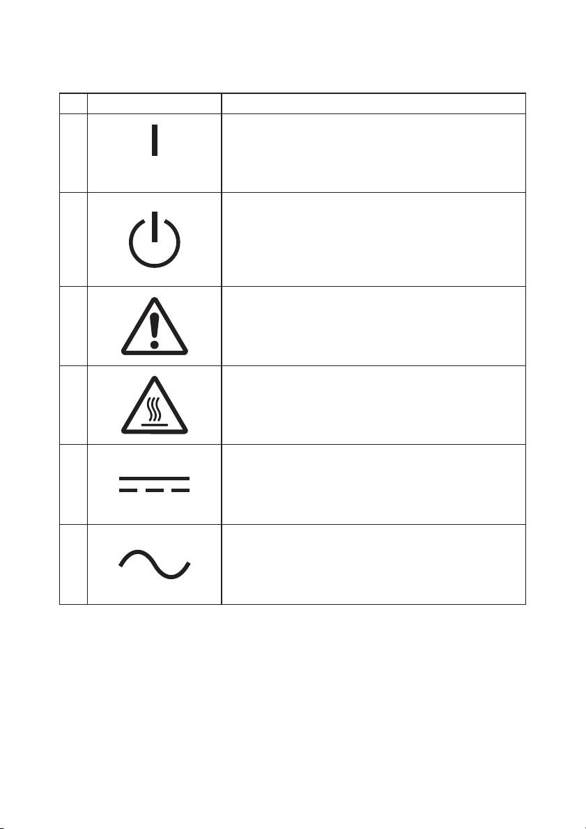
'HVFULSWLRQGHVV\PEROHVGHVpFXULWpDI¿FKpVVXUO¶pTXLSHPHQW
No. Symbole Description
1
« MARCHE » (alimentation)
Pour indiquer la connexion à l’alimentation, au moins
les interrupteurs principaux ou leurs positions.
2
3
4
5
6
Veille
3RXULGHQWL¿HUO¶LQWHUUXSWHXURXODSRVLWLRQGH
l’interrupteur avec pour connaitre quelle partie de
O¶pTXLSHPHQWHVWHQPDUFKHD¿QGHOHPHWWUHHQ
mode veille.
Avertissement/Mise en garde général(e)
3RXULGHQWL¿HUXQDYHUWLVVHPHQWPLVHHQJDUGH
JpQpUDOH
$WWHQWLRQVXUIDFHFKDXGH
Pour indiquer que l’élément marqué peut être chaud
HWQHGRLWSDVrWUHWRXFKpVDQVSUHQGUHJDUGH
Courant continu
3RXULQGLTXHUVXUODSODTXHG¶LGHQWL¿FDWLRQTXH
l’équipement ne doit être branché que sur du courant
FRQWLQXSRXULGHQWL¿HUOHVERUQHVDSSURSULpHV
Courant alternatif
3RXULQGLTXHUVXUODSODTXHG¶LGHQWL¿FDWLRQTXH
l’équipement ne doit être branché que sur du courant
DOWHUQDWLISRXULGHQWL¿HUOHVERUQHVDSSURSULpHV
Page 98

Table des matières
1. Aspect et nom des composants························································· 5
1-1. Nom des composants································································ 5
1-2. Contenu de l'emballage····························································· 6
2. Adaptateur CA··················································································· 7
3. Caractéristiques du papier································································· 8
3-1. Largeur du papier······································································ 8
3-2. Épaisseur du papier··································································· 8
3-3. Rouleau de papier····································································· 8
3-4. Papier thermique recommandé················································· 9
4. Préparation······················································································ 10
4-1. Branchement du câble d'interface (sur l'imprimante)·············· 11
4-2. Branchement du câble d'interface (sur le PC)························· 13
4-3. Branchement du câble d'ouverture du tiroir···························· 15
4-4. Branchement de l'adaptateur CA et du cordon d 'alimentation······· 16
4-5. Débranchement de l'adaptateur CA·········································19
4-6. Installation de l'imprimante····················································· 20
4-7. Mise sous tension···································································· 24
4-8. Installation du logiciel de l'imprimante···································· 25
5. Chargement du papier·····································································26
5-1. Ouverture du panneau supérieur············································ 26
5-2. Réglage de la largeur du papier (largeur : 58mm /
80mm) ·················································································· 28
5-3. Chargement du papier····························································· 30
5-4. Fermeture du panneau supérieur············································ 32
6. Tableau de commande···································································· 33
6-1. Tableau de commande···························································· 33
6-2. Indications d'erreurs································································ 34
7. Prévention et élimination des bourrages papier······························ 36
7-1. Prévention des bourrages papier············································· 36
7-2. Élimination des bourrages papier············································ 36
7-3. Si le panneau supérieur ne s'ouvre pas··································· 37
8. Dépannage······················································································ 40
8-1. Problèmes à la mise sous tension et autres erreurs················ 40
8-2. Problèmes de découpe···························································· 40
8-3. Problèmes d'impression···························································
9. Mode spécial (essai d'impressio n, menu de configuration...)··························· 42
9-1. Essai d'impression··································································· 42
3
41
Page 99

9-2. Modification de la configuration·············································· 44
9-3. Paramètres de configuration··················································· 54
9-4. Réglages de configuration LAN(Imprimantes avec
interfaces série, USB et LAN)················································ 60
9-5. Vidage HEX·············································································· 63
9-6. Trace des commandes ····························································64
9-7. Impression d'échantillons························································ 65
10. Nettoyage régulier········································································· 70
10-1. Nettoyage du chariot et du mécanisme de transport du
papier····················································································70
10-2. Nettoyage du cylindre··························································· 71
10-3. Nettoyage de la tête thermique·············································72
11. Interface························································································ 73
11-1. Interface série······································································· 73
11-2. Interface USB········································································ 76
11-3. Interface LAN········································································ 76
11-4. Connecteur d'ouverture du tiroir··········································· 77
11-5. Caractéristiques de l'alimentation·········································· 79
12. Spécifications················································································· 80
12-1. Caractéristiques générales·····················································80
12-2. Caractéristiques de l'élément de découpe····························· 83
12-3. Caractéristiques des rouleaux de papier································ 83
12-4. Caractéristiques des interfaces·············································· 83
12-5. Caractéristiques environnementales······································ 84
12-6. Caractéristiques de fiabilité··················································· 85
13. Précautions d'usage······································································· 86
13-1. Précautions concernant le papier·········································· 86
13-2. Précautions concernant l'élément de découpe······················ 87
13-3. Précautions concernant l'impression de codes barres/codes
2D························································································· 87
13-4. Précautions liées à l'utilisation de l'interface USB·················· 88
13-5. Précautions liées à l'utilisation de l'interface LAN·················· 88
13-6. Précautions liées à l'installation············································· 89
13-7. Précautions liées à l'utilisation du connecteur modulair········ 89
4
Page 100

1. Aspect et nom des composants
1-1. Nom des composants
Modèle standard
Panneau central
Panneau
supérieur
Panneau avant
Modèle avec alimentation intégrée
• Panneau supérieur
S'ouvre pour remplacer le papier.
• Levier de déverrouillage
Sert à ouvrir le panneau supérieur.
• Commutateur de marche/arrêt
Permet de mettre en marche/d'arrêter l'imprimante (ON/OFF).
• Tableau de commande
Comprend les boutons de commande de l'imprimante et les voyants qui indiquent
l'état de l'imprimante.
• Panneau avant
Peut être enlevé en cas de bourrage à la découpe ou si le panneau supérieur ne
s'ouvre pas.
• Prise d'alimentation
Branchez le cordon d'alimentation à cet endroit.
Levier de
déverrouillage
Tableau de
commande
Commutateur de
marche/arrêt
d'alimentation
Prise
5
 Loading...