

Page 1

Chapter 1
Front Cover
OKIDATA
OL810e LED PAGE PRINTER
Service Manual
ODA P/N: 59270001
Page 2

Manual Copyright
OKIDATA is a registered trademark of Oki America, Inc.
OKIDATA est une marque déposée de Oki America, Inc.
Page 3
Chapter 1
%1.1 System Configuration
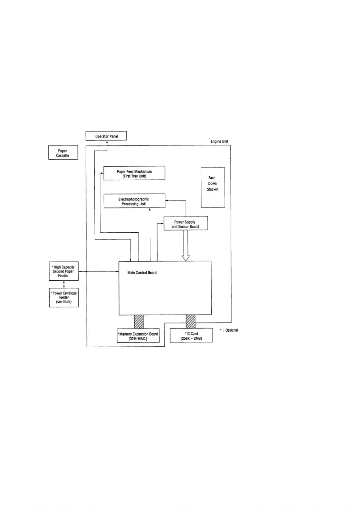
1.1 System Configuration
OL810e consists of control and engine blocks in the standard configuration, as shown in Figure 1-1.
In addition, the options marked with asterisk(*) are available.
Figure 1-1
Note: Power Envelope Feeder is compatible with OL400e series printers.
Page 4
%1.2 Printer Configuration
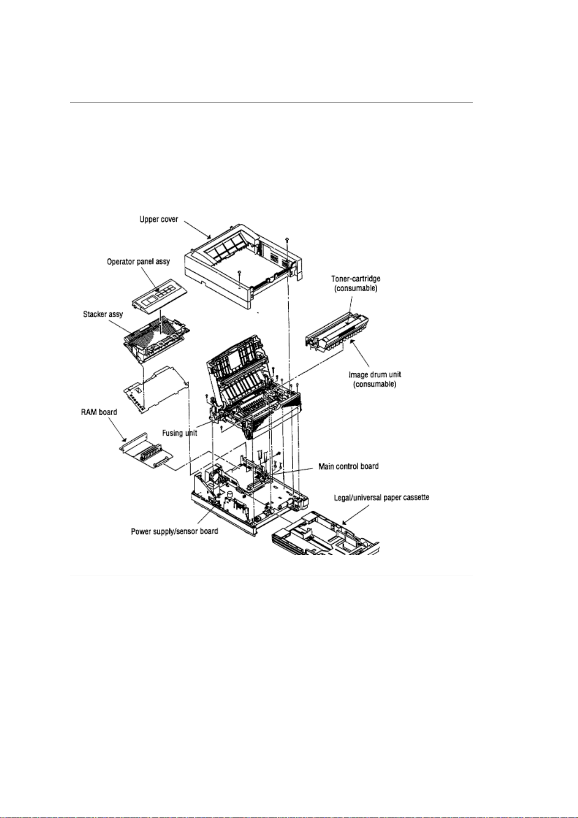
1.2 Printer Configuration
The printer unit consists of the following hardware components:
• Electrophotographic Processor
• Paper Feeder
• Controller
• Operator Panel
• Power Supply Unit
The printer unit configuration is shown in Figure 1-2.
Page 5
%1.3 Options available for use with OL810e
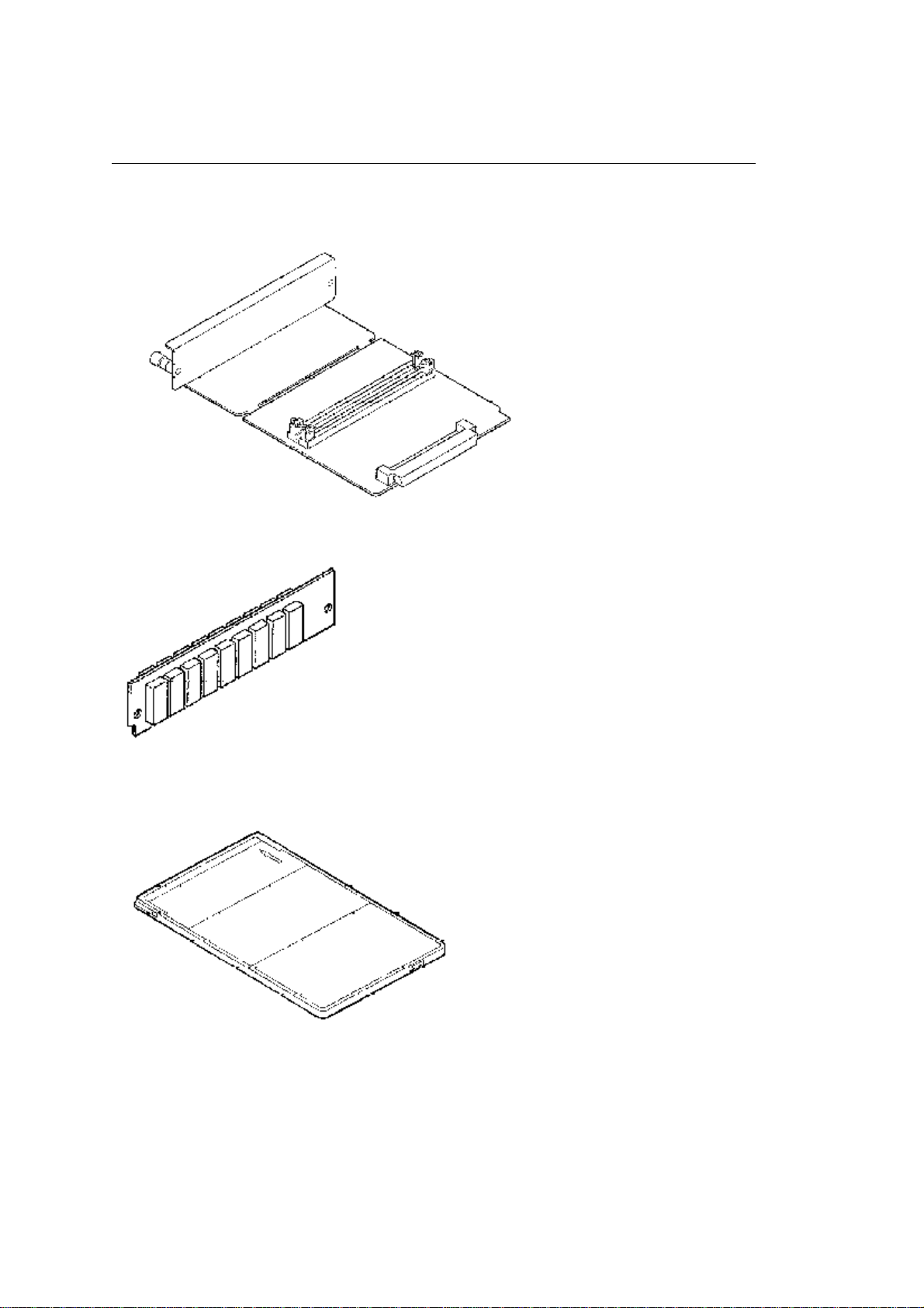
1.3 Optional Configuration
The options shown below are available for use with OL810e. These are available separately from
the printer unit.
(1) Memory Expansion Board (1MB to 32MB)
(2) SIMM Memory SIMM memory is available with memory of 1MB (min.) to 16MB (max.). The
access time of SIMM memories are 60ns, 70ns, 80ns, and 100ns.
(3) IC Card
(4) Universal Paper Cassette
Page 6
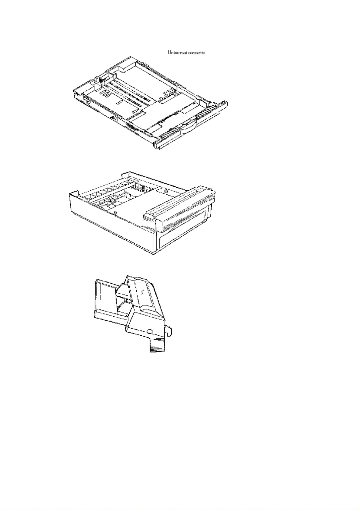
(5) High Capacity Second Paper Feeder
(6) Power Envelope Feeder
Page 7

%1.4 Specification
1.4 Specification
(1) Type Desktop
(2) External dimensions Height 7.9 (200 mm) (excludes protruding Width 12.8 (370 mm)
portion) Depth 14.6 (370 mm)
(3) Weight 10 kg
(4) Developing method Dry electrophotography Exposing method LED stationary head
(5) Paper used <Type>
• Standard paper Xerox 4200 (20 lbs)
• Application paper (manual face-up feed) Label Envelope OHP paper (transparency)
<Size>
• Standard sizes Letter Legal Executive CON-10 Monarch DL C5 COM-9 Envelope A4
A5 B5 (JIS) A6
• Applicable sizes Width: 3.87 to 8.5 (116 to 216 mm) Length: 5.83 to 14 (148 to 355.6 mm)
<Thickness> Automatic feed: 16 to 36 lbs (60 to 135 g/m 2 ) Manual feed: Label, OHP paper
(transparency) Envelope
(6) Printing speed First print: 25 sec. Continuous print: 8 sheets/min. for letter size paper
Warm-up time: 60 sec. [at room temperature 77°F (25°C) and rated voltage (120 VAC)]
(7) Paper feeding method Automatic feed or manual feed
(8) Paper delivery method Face down/face up
(9) Resolution 600 x 600 dots/inch
(10)Power input 120 VAC + 5.5%, -15% 230 VAC + 6%, -14% 230 VAC + 10%, -10%
(11)Power consumption Peak: Approx. 600W Typical operation: Approx. 130W Idle: Approx.
41W Power save mode: Approx. 13W
(12)Temperature and humidity During operation: 50 to 90°F (10 to 32°C) In storage: -14 to
112°F (-20 to 50°C)
(13) Noise During operation: 48 dB (A) or less Standby: 36 dB (A) or less Quiet mode: 32 dB
(A) or less
(14)Consumables Toner cartridge kit 2,000 (5% duty) Image drum cartridge 20,000 (at
continuous printing) 15,000 (3 page/job) 10,000 (1 page/job)
Page 8
%1.5 Safety Standards - Certification & Warning Labels
1.5 Safety Standards
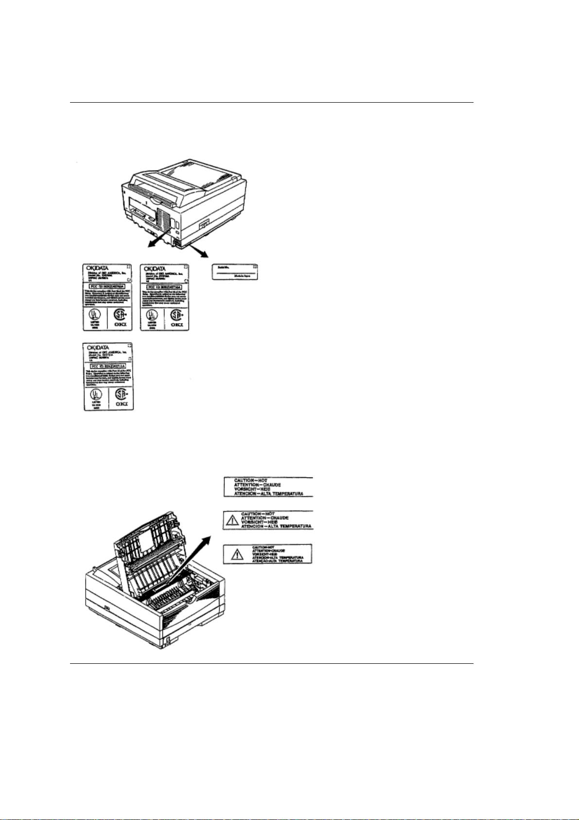
1.5.1 Certification Label
The safety certification and serial number labels are affixed to the printer in the positions
described below.
1.5.2 Warning Label
The warning labels are affixed to the sections which may cause bodily injury.
Follow the instructions on warning labels during maintenance.
Page 9
%1.5.3 Warning/Caution Marking
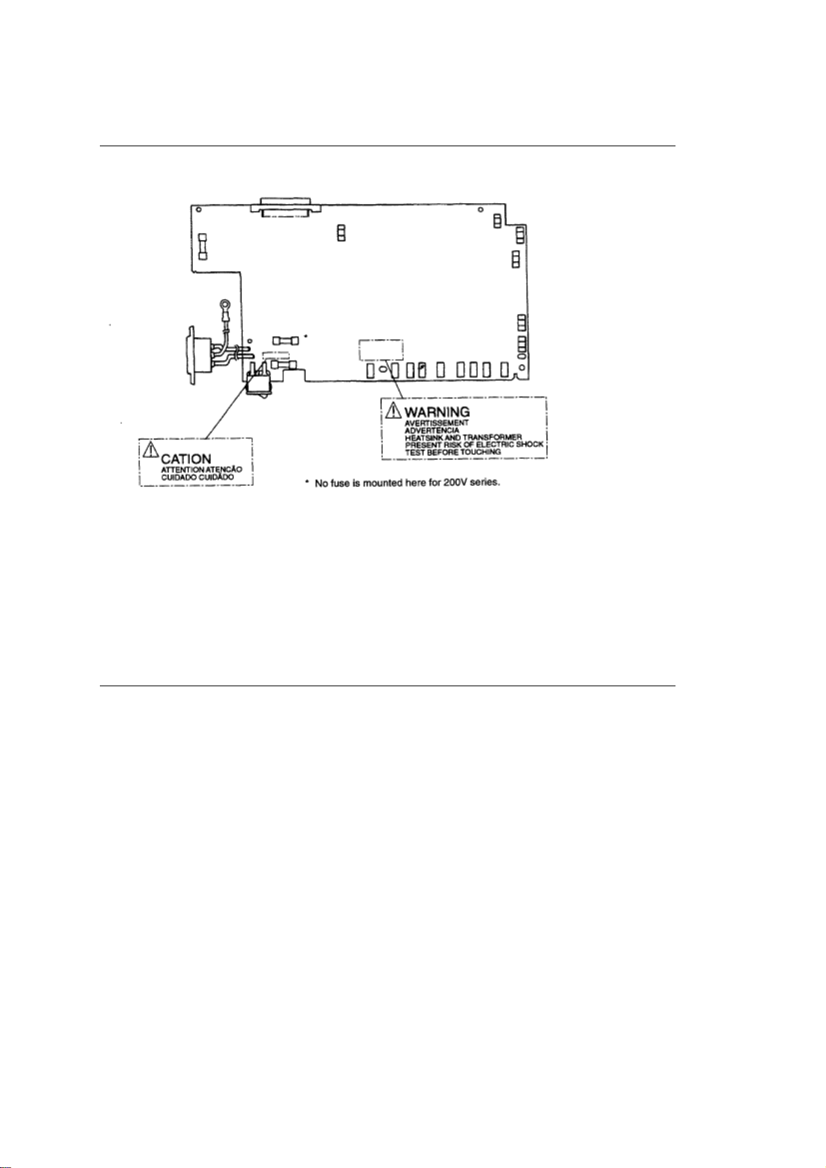
1.5.3 Warning/Caution Marking
The following warning and caution markings are made on the power supply/sensor board.
ENGLISH Heatsink and transformer core present risk of electric shock. Test before touching.
FRENCH Le dissipateur thermique et le noyau du transformateur présentent des risques de choc
électrique. Testez avant de manipuler.
SPANISH Las disipadores de color el núcel del transformador pueden producir un choque
eléctrico. Compruebe antes de tocar. PORTUGUESE O dissipador de calor e o núcleo do
fransiormador apresentam risco de choque elétrico. Teste antes de focar.
ENGLISH Circuits maybe live after fuses open.
FRENCH Il se peut que les circuits soient sous tension une fois que les fusibles ont éfé rerirés.
SPANISH Las circuitos pueden estar activos una vez que se hayan abierio los fusibles.
PORTUGUESE Os circuitos podem estar energizados após os fusiveis se queimarem.*
Page 10

Chapter 2
%Operation Description
2. OPERATION DESCRIPTION
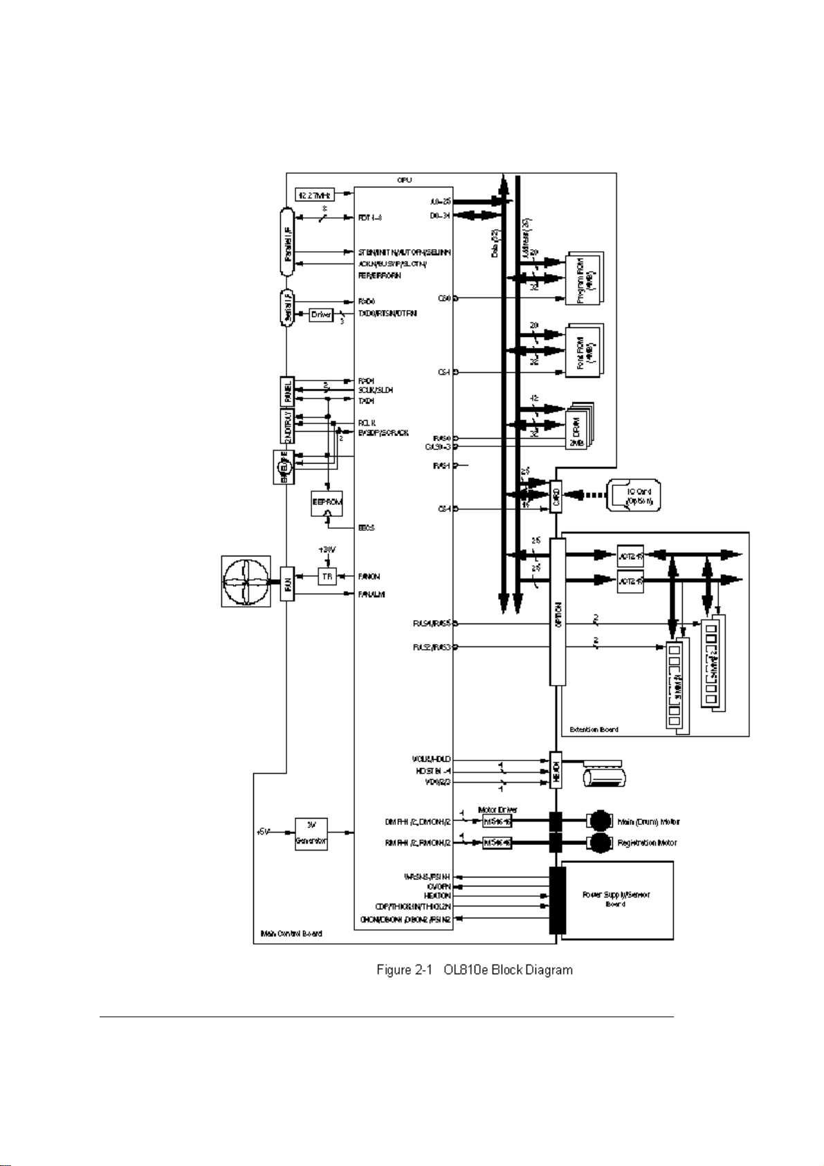
OL810e consists of a main control board, a power supply/sensor board, an operator panel, an
electrophotographic process mechanism, and revision for illumination of LED head.
The main control board receives data via the host I/F, it then decodes, edits and stores the data in
memory. After completing the editing of a single page of data, it references the font memory and
generates bit image data, which is transferred to the LED head in one dot line units.
Through the electrophotographic process mechanism, the data is printed on the paper.
The operator panel is used for operations and status display.
OL810e block diagram is shown in Figure 2-1.
Page 11
Page 12

%2.1 Main Control Board
2.1 Main Control Board
The main control board consists of a single chip CPU, a program ROM, a font ROM, four DRAMs, an
EEPROM, a host interface circuit, and a mechanism driving circuit.
(1) Single chip CPU
The single chip CPU is a custom CPU (32-bit internal bus, 32-bit external bus, 25.54-MHz clock, with
input frequency from a 12.27-MHz clock) which incorporates the RISC CPU and its peripheral devices,
and has the following functions:
Built-in device
Chip select controller Control of ROM, DRAM and I/O device Bus controller
DRAM controller
DMA controller Transfer of image data from DRAM to video output port
Parallel interface controller Control of Centronics parallel interface
Serial interface controller Control of RS-232C serial interface
Video output port Control of LED head
LED STB output port
Timer Generation of various control timing
Serial I/O port Control of operator panel, EEPROM, and options
I/O port Input and output of sensor and motor signals
(2) Program and Font ROMs
The Program and Font ROMs store the equipment program and various types of fonts. EPROM or Mask
ROM is used as Program and Font ROMs. The mounting locations of these Program and Font ROMs
vary depending on the type of the ROMs (for the mounting location see Section 7.4).
Function
Monitoring of paper running and paper size
(3) DRAM
The DRAM is a 2MB resident memory which is used as a buffer, that stores edited data, image data, DLL
data and macro data.
(4) EEPROM
1,024-bit Electrically Erasable PROM (EEPROM), is loaded with the following kinds of data:
• Menu data • Various counter data (page counter, drum counter) • Adjusting parameters (LED head drive
time, print start position, paper feed length)
(5) Parallel Interface
Parallel data is received from a host system via parallel interface which conforms to the Centronics
specification.
(6) RS232C Serial Interface
Serial data is sent to and received from a host system via serial interface which conforms to EIA
RS232C.
Following items are selectable:
Flow control: DTR HI/DTR LO/XONXOFF/RBSTXON Baud rate: 300/600/1200/2400/4800/9600/19200
Data bits: 7 BITS/8 BITS Parity: NONE/EVEN/0DD Minimum busy: 200 mSEC/1 SEC
Page 13
%2.2 Power Supply/Sensor Board
2.2 Power Supply/Sensor Board
The power supply/sensor board consists of an AC filter circuit, a low voltage power supply circuit, a high
voltage power supply circuit, heater drive circuit, and photosensors.
(1) Low Voltage Power Supply Circuit
This circuit generates the following voltages.
Output voltage Use
+5 V Logic circuit supply voltage
+30 V Motor and fan drive voltage and source voltage for high-voltage supply
+8 V RS-232C line voltage
8 V RS-232C line voltage and PS board supply voltage
+3.3V LED head supply voltage
(2) High Voltage Power Supply Circuit
This circuit generates the following voltages required for electrophotographic process from +5 V,
according to the control sequence from the main control board. When cover open state is detected, +5 V
supply is interrupted automatically to stop the supply of all high-voltage outputs.
Output
CH -1.35 KV Voltage applied to charging roller
DB -300 V/+300 V Voltage applied to developing roller
SB -450 V/ 0 V Voltage applied to toner supply roller
TR +500 V to +4 KV/-750 V Voltage applied to transfer roller Variable
CB +400 V Voltage applied to clearing roller
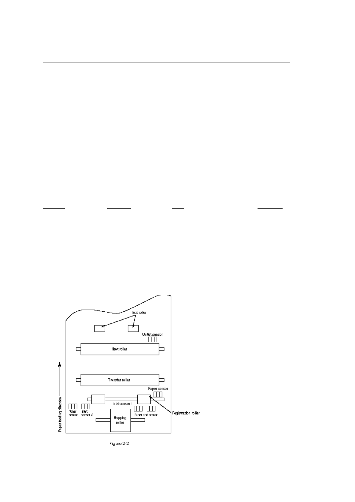
(3) Photosensor
The photosensor mounted on this power supply/sensor board monitors the status of paper being fed
through the printer during printing.
The sensor layout diagram is shown in Figure 2-2.
Voltage Use Remarks
Page 14

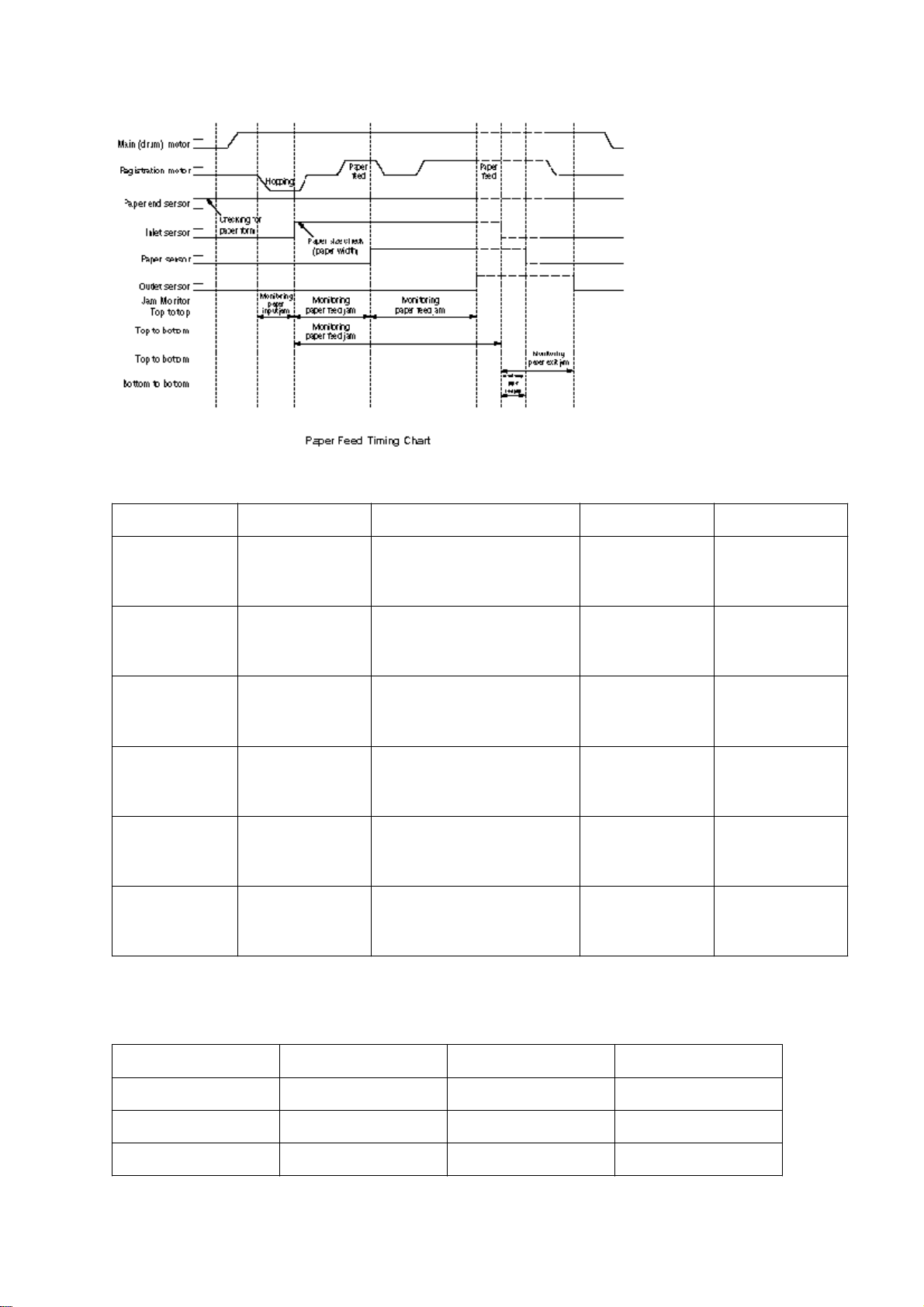
Function Sensing state
Inlet sensor 1 Detects the leading part of the
paper and gives the monitor
timing for switching from
hopping operation to feeding
operation. Monitors paper
feeding situation and paper
size based on the paper
arrival time and running time.
Intel sensor 2 Detects the paper width. ON: A4 or larger OFF:
Paper sensor Detects the leading portion of
the paper. Monitors the paper
feeding situation.
Outlet sensor Monitors the paper feeding
and size according to the time
of arrival to and leaving past
the sensor.
Paper end sensor Detects the end of the paper. ON: Paper exists. OFF: No
Toner low sensor Detects the lack of
toner.Sensor
ON: Paper exists. OFF: No
paper exists.
Smaller than A4
ON: Paper exists. OFF: No
paper exists.
ON: Paper exists. OFF: No
paper exists.
paper exists.
- - - - -
Page 15
%2.3 Electrophotographic Process
2.3 Electrophotographic Process
2.3.1 Electrophotographic Process Mechanism
This mechanism actuates the printing of image data supplied by the main control board on the paper by
electrophotographic process.
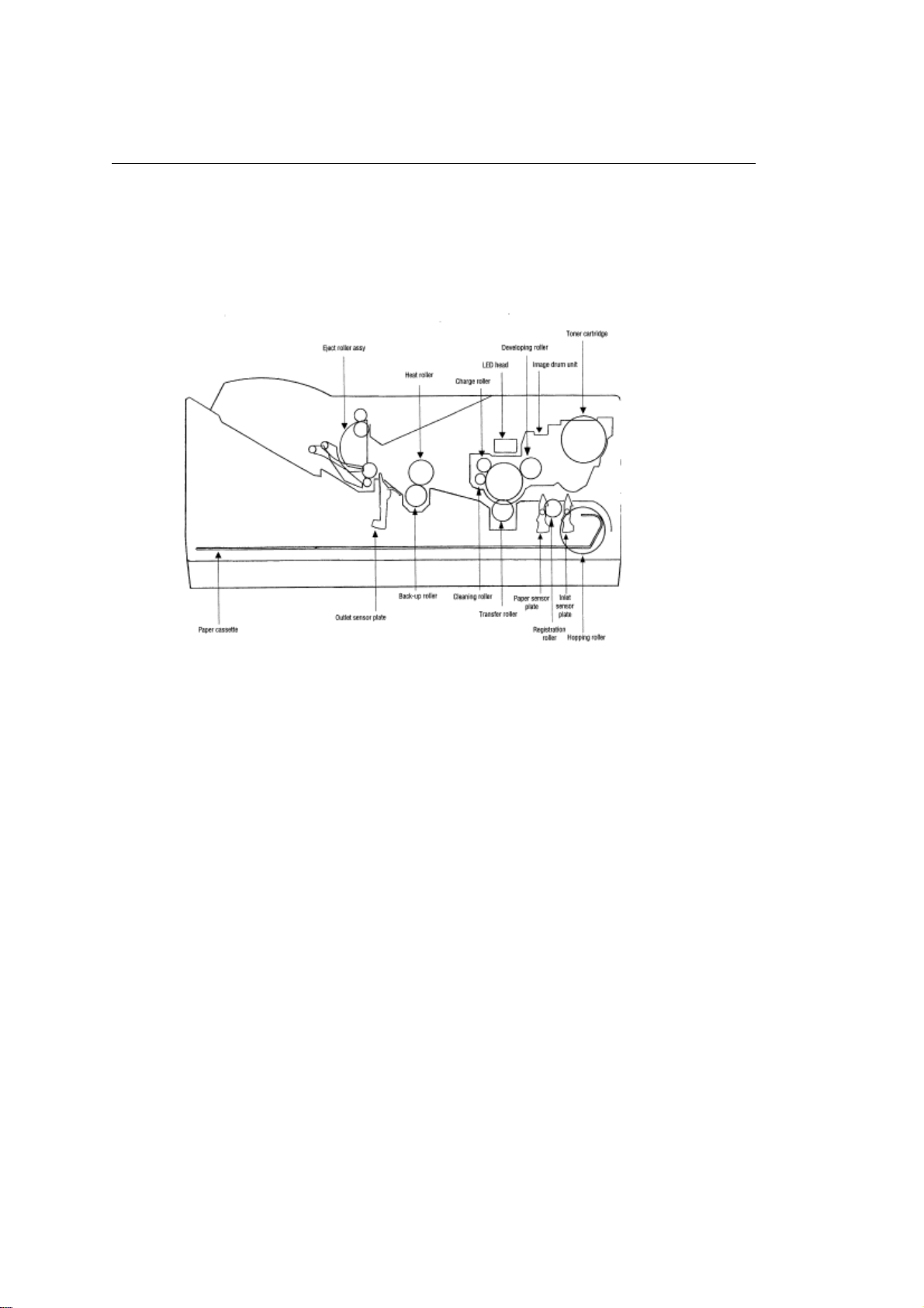
The layout of the electrophotographic process mechanism is shown in Figure 2-3.
(1) Image Drum Unit
The image drum unit consists of a sensitive drum, a charger, and a developer. The unit forms a toner
image on the sensitive drum, using a electrostatic latent image formed by the LED head.
(2) Registration Motor
The registration motor is a pulse motor of 48 steps/rotation with two-phase excitement by the signal from
the main control board. It drives the hopping and registration rollers via two one-way clutches according
to the direction of rotation.
(3) Main (Drum) Motor
The main or drum motor is a pulse motor of 48 steps/rotation with two-phase excitement by the signal
from the main control board and is the main motor of this mechanism.
(4) LED Head
Image data for each dot line from the main control board is received by the shift register and latch
register. The 4992 LED's are driven to radiate the image data on the image drum.
(5) Fuser
The fuser consists of a heater, a heat roller, a thermistor and a thermostat.
The AC voltage from the power supply/sensor board is applied to the heater controlled by the HEATON
signal from the main control board. This AC voltage heats the heater. The main control board monitors
the heat roller temperature via the thermistor, and regulates the heater roller to keep it at a designated
temperature in the menu, depending on the thickness of the paper (tray 1&2: light=165°C, medium
light=170°C, medium=175°C, medium heavy and heavy=195°C; manual feeding and power envelope
feeder: light=175°C, medium light=180°C, medium=185°C, medium heavy=190°C, heavy=195°C) by
connecting or disconnecting the AC voltage supply to the heater.
When an abnormal rise of the heater roller temperature takes place, the thermostat of the heater voltage
Page 16

supply circuit becomes active and forcibly cuts the AC voltage supply.
The temperature setting of the fuser can be changed through operator panel setting.
Page 17
%2.3.2 Electrophotographic Process
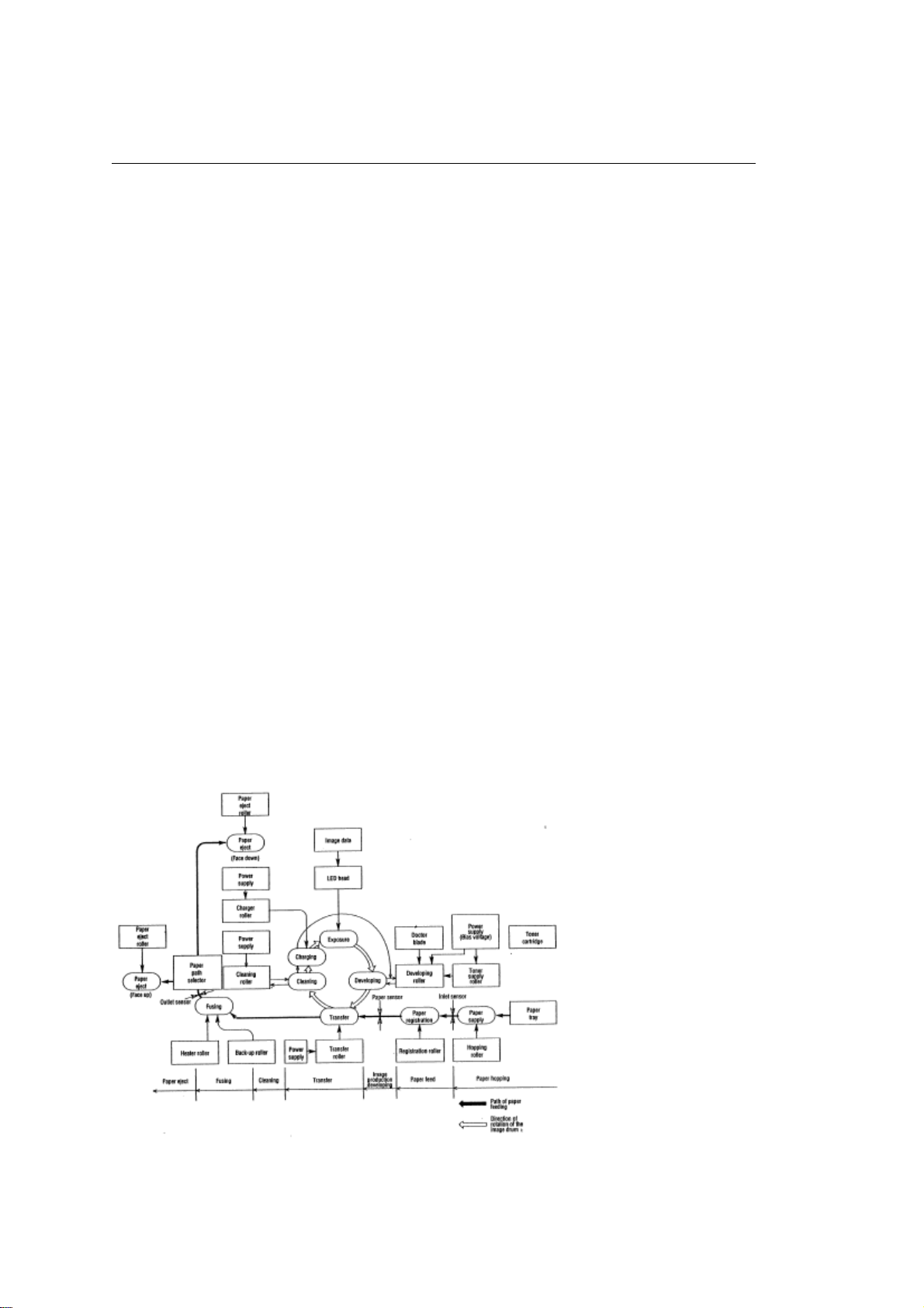
2.3.2 Electrophotographic Process
The electrophotographic processing is outlined below. The electrophotographic printing process is shown
in Figure 2-4.
1 Charging
The surface of the image drum is charged uniformly with a negative charge by applying the negative
voltage to the charge roller.
2 Exposure
Light emitted from the LED head irradiates the negatively charged surface of the image drum. The
surface potential of the irradiated portion of the image drum surface becomes lower, forming the
electrostatic latent image associated with the print image.
3 Developing and toner recovery
When the negatively charged toner is brought into contact with the image drum, it is attracted to the
electrostatic latent image by static electricity, making the image visible.
At the same time, the residual toner on the image drum is attracted to the developing roller by static
electricity.
4 Transfer
When paper is placed over the image drum surface, the positive charge which is opposite in polarity to
that of the toner, is applied to the reverse side of the paper by the transfer roller. The toner is attracted by
the positive charge and is transferred onto the paper. This results in the transfer of the toner image
formed on the image drum onto the paper.
5 Temporary cleaning
Residual toner which remains on the image drum without being transferred is evened out by the cleaning
roller and is temporarily attracted to the cleaning roller by static electricity.
6 Fusing
The toner image transferred onto the paper is fused to the paper by heat and pressure.
An electrophotographic process timing chart is shown in Figure 2-5.
Page 18

Page 19

%2.3.3 Process Operation Descriptions
2.3.3 Process Operation Descriptions
(1) Hopping and Feeding
Hopping and feeding motions are actuated by a single registration motor in the mechanism as shown
below:
The registration motor turning in direction "a" drives the hopping roller. The registration motor turning in
direction "b" drives the registration roller. The registration and hopping gears have one-way bearing, so
turning any of these gears in the reverse direction will not transmit the motion to the corresponding roller.
(a) Hopping
1 For hopping, the registration motor turns in direction "a" (clockwise direction) and drives the hopping
roller to advance the paper until the inlet sensor turns on (in this case, the registration gear also turns, but
the registration roller is pre-vented from turning by the one-way bearing).
2 After inlet sensor is turned on by the paper advance, the paper is further ad-vanced to a predetermined
distance until the paper hits the registration roller (the skew of the paper can thus be corrected).
(b) Feeding
1 When hopping is completed, the registration motor turning in direction "b" (counter-clockwise direction)
drives the registration roller to advance the paper (in this case, the hopping gear also turns, but the
hopping roller is prevented from turning by the one-way bearing).
Page 20
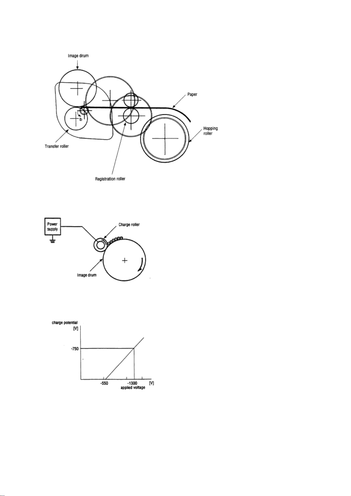
2 The paper is further advanced in synchronization with the print data.
(2) Charging
Charging is actuated by the application of the DC voltage to the charge roller that is in contact with the
image drum surface.
The charge roller is composed of two layers, a conductive layer and a surface protective layer, both
having elasticity to secure good contact with the image drum. When the DC voltage applied by the power
supply exceeds the threshold value, charging begins. The applied voltage is proportional to the charge
potential, with offset of approximately 550V.
(3) Exposure
Light emitted by the LED head irradiates the image drum surface with a negative charge. The surface
potential of the irradiated portion of the image drum drops, forming an electrostatic latent image
associated with the image signal.
Page 21
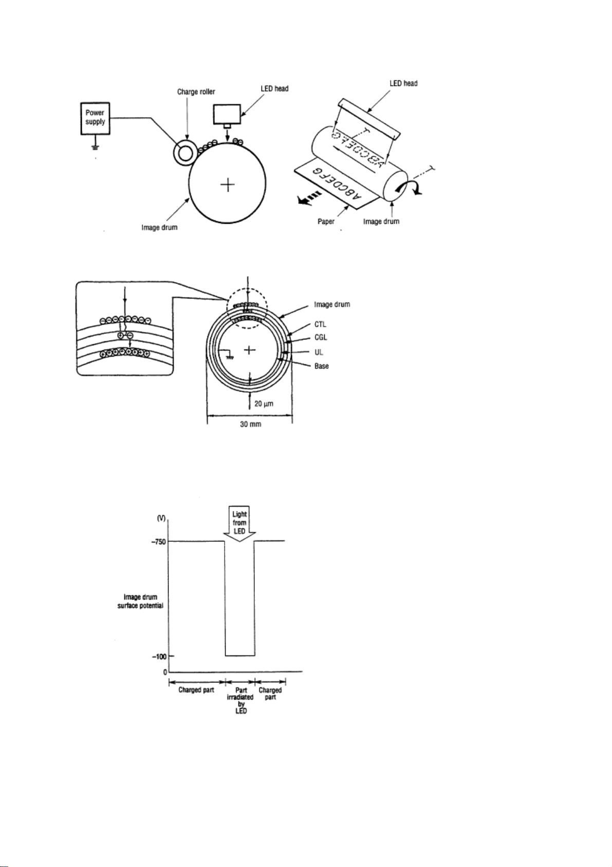
The image drum is coated with an underlayer (UL), a carrier generation layer (CGL), and carrier transfer
layer (CTL) on aluminum base. The organic photo conductor layer (OPC), comprising CTL and CGL, is
about 20 µm thick.
The image roller surface is charged to about 750 V by the contact charge of the charge roller.
When the light from the LED head irradiates the image drum surface, the light energy generates positive
and negative carriers in the CGL. The positive carriers are moved to the CTL by an electrical field acting
on the image drum. Likewise, the negative carriers flow into the aluminum layer (ground).
The positive carriers moved to the CTL combine with the negative charges on the image drum surface
accumulated by the contact charge of the charge roller, lowering the potential on the image drum surface.
The resultant drop in the potential of the irradiated portion of the image drum surface forms an
electrostatic latent image on it. The irradiated portion of the image drum surface is kept to about 100 V.
Page 22
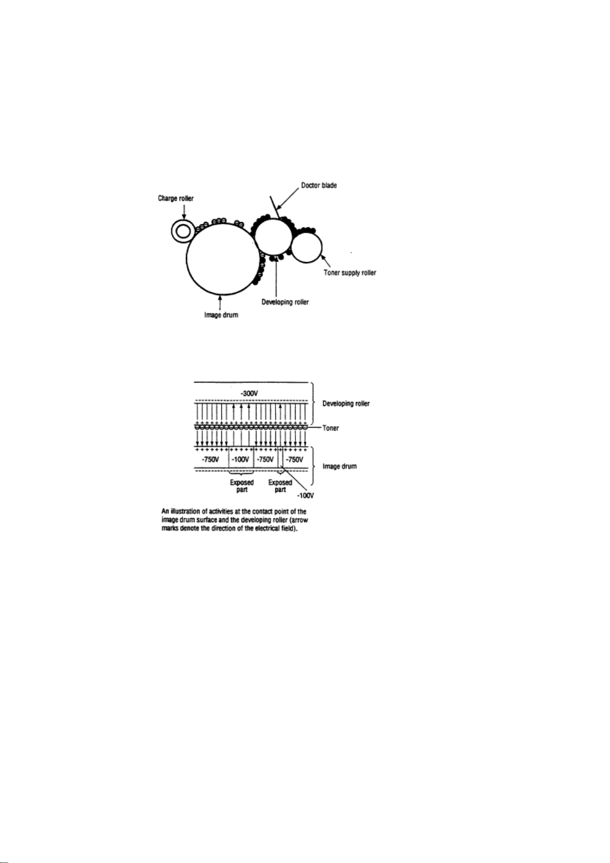
(4) Developing
Toner is attracted to the electrostatic latent image on the image drum surface, converting it into a visible
toner image. Developing takes place through the contact between the image drum and the developing
roller.
1 As the toner supply roller rotates while rubbing on the developing roller, a friction charge is generated
between the developing roller and the toner, allowing the toner to be attracted to the developing roller (the
developing roller surface is charged positive and the toner, negative).
2 The toner attracted to the developing roller is scraped off by the doctor blade, forming a thin coat of
toner on the developing roller surface.
3 Toner is attracted to the exposed portion (low-potential part) of the image drum at the contact of the
image drum and the developing roller, making the electrostatic latent image visible.
Note: The bias voltage required during the developing process is supplied to the toner supply roller and
the developing roller, as shown below. 450 VDC is supplied to the toner supply roller, 300 VDC to the
developing roller.
Page 23
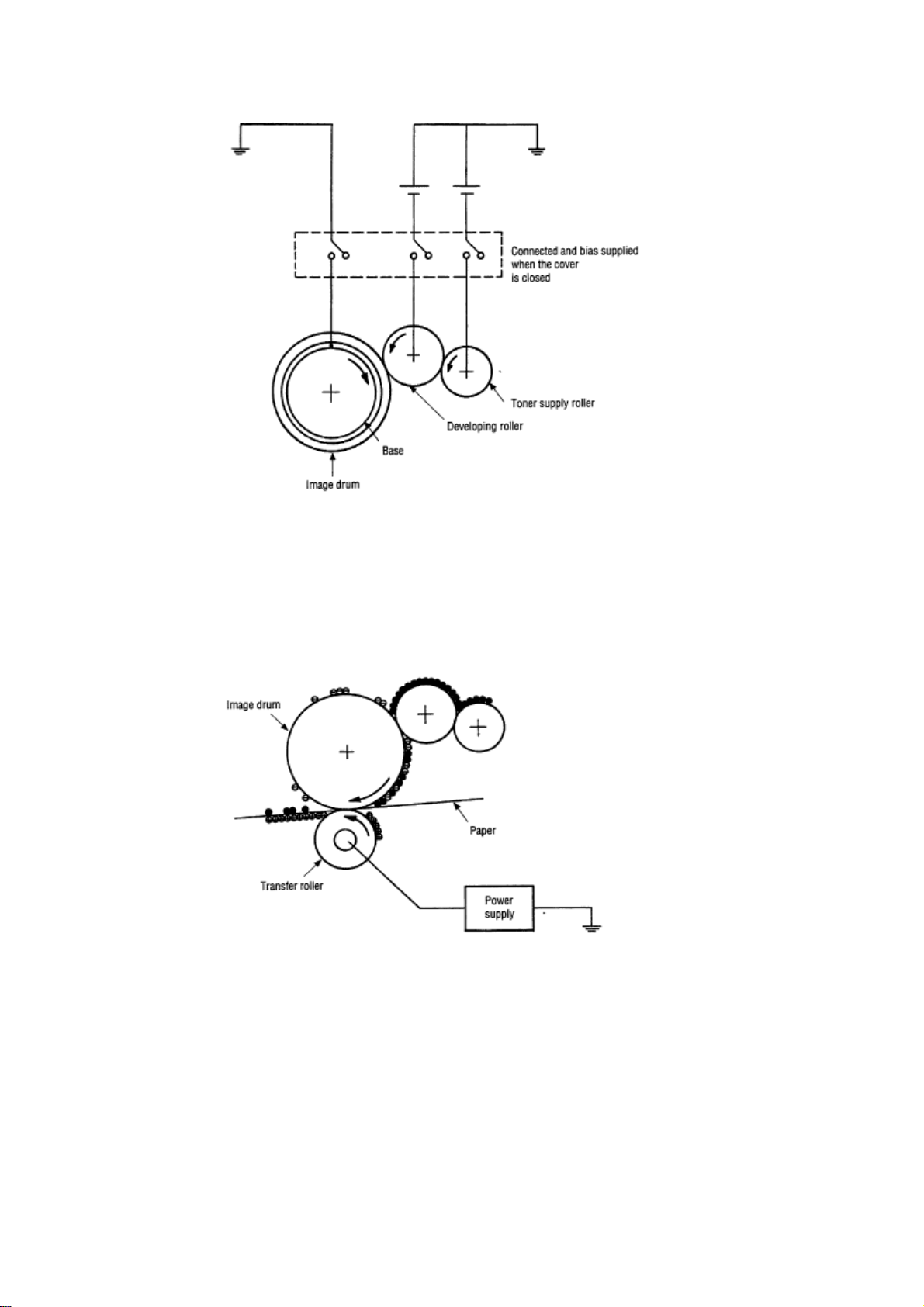
(5) Transfer
The transfer roller is composed of conductive sponge material, and is designed to get the image drum
surface and the paper in a close contact.
Paper is placed over the image drum surface, and the positive charge, opposite in polarity to that of the
toner, is applied to the paper from the reverse side.
The application of a high positive voltage from the power supply to the transfer roller causes the positive
charge inducement on the transfer roller surface, transferring the charge to the paper as it contacts the
transfer roller. The toner with negative charge is attracted to the image drum surface, and it is transferred
to the upper side of the paper due to the positive charge on the reverse side of the paper.
(6) Fusing
When the transfer is completed, the toner image is fused to the paper by heat and pressure as the paper
with unfused toner image passes between the heater roller and the back-up roller. The heater roller with
Teflon coating incorporates a 400W heater (Halogen lamp), which generates heat.
A thermistor which is in contact with the heater roller regulates the temperature of the heater roller to a
designated temperature in the menu, depending on the thickness of the paper (tray 1&2: light=165°C,
medium light=170°C, medium=175°C, medium heavy and heavy=195°C/ manual feeding and power
envelope feeder: light=175°C, medium light=180°C, medium=185°C, midium heavy=190°C,
heavy=195°C). A safety thermostat cuts voltage supply to the heater off by opening the thermostat in the
event of abnormal temperature rises.
The back-up roller is held under a pressure of 7.52 kg applied by the pressure spring on each side.
Page 24
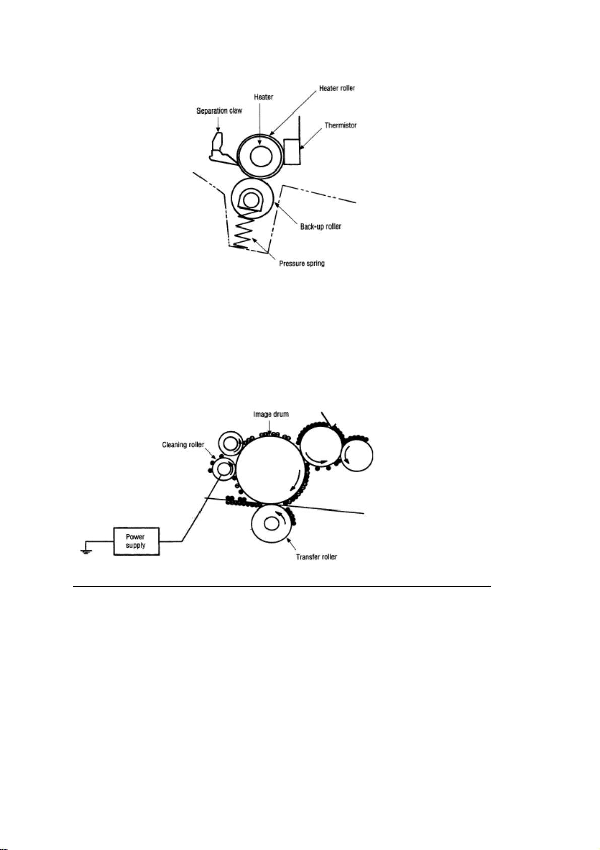
(7) Cleaning
When the transfer is completed, the residual toner left on the image drum is attracted to the cleaning
roller temporarily by static electricity, and the image drum surface is cleaned.
(8) Cleaning of rollers
The charge, transfer and cleaning rollers are cleaned for the following cases:
• Warming up when the power is turned on. • Warming up after the opening and closing of the cover. •
When the number of sheets accumulated reaches 10 or more, and the printout operation ends.
Changes in bias voltage applied to each roller move the attaching toner off the roller to the image drum
and return it to the developer.
Page 25
%2.3.4 Revision of LED Head Illumination
2.3.4 Revision of LED Head Illumination
An LED correcting head, which is capable of correcting the illumination of the LED for each dot, is being
used in this printer. LED illumination correction function of 16 steps is carried out by using an EEPROM
which is installed in the LSI that maintains the LED illumination correction values, and an LED correction
drivers (MSM6731BWAF) together as a pair.
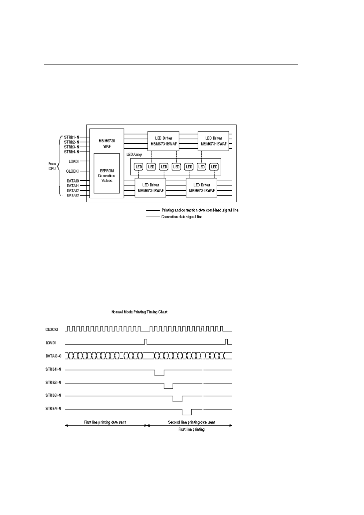
The LED correcting head consists of the correction control LSI (MSM6730WAF), LED drivers
(MSM6731BWAF), and an LED array. The block diagram of the LED correcting head is shown below.
The existing LED head receives the printing data from the CPU directly at its LED drivers. With the LED
correcting head, a correction control LSI (MSM6730WAF) is connected between the CPU and LED
drivers, so the printing data is input to the LED drivers through the correction control LSI. In order to
maintain compatibility with the existing LED head, the printing operation of the LED correcting head is
carried out through identical sequence.
The LED correcting head is a 600 dpi head, with the LED drivers located on both sides of the LED array
with a 300 dpi pitch spacing. The printing and correction data obtained from the CPU through four signal
lines are sent to the LED array.
The printing operation timing chart is shown below.
The printing operation is carried out in normal mode. Under ordinary circumstances such as when the
power is turned on or when LOADI signal level is low, the normal mode is enabled.
The printing operation is carried out in the following sequence. First, the printing data DATAI3 through
DATAI0 are stored, sequentially shifted, in the shift registers of the LED drivers, by the printing data
Page 26
synchronous clock, CLOCKI. Then the printing data stored in shift registers are latched by the high level
pulse of LOADI. The latched printing data turns the LEDs on by STRB1I-N through STRB4I-N and
actuates printing.
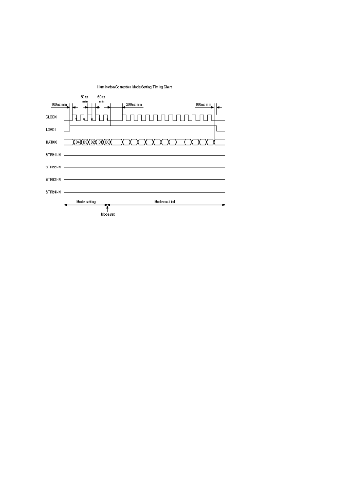
The mode setting timing chart during illumination correction is shown below.
The mode setting is carried out in the following manner. LOADI is fixed at high level, and DATAI0 which
comes up following this is 4-data latched with the timing of the fall of CLOCKI. The illumination correction
mode is selected based on the latched 4-data combination. Then the mode becomes valid at the fifth fall
of CLOCKI.
The period during which the illumination correction mode is valid is from the fall of the fifth CLOCKI and
while the level of LOADI is high. When the level of LOADI becomes low, the illumination correction mode
is terminated, and the head returns to the normal mode, which is mode with which the printing is normally
carried out.
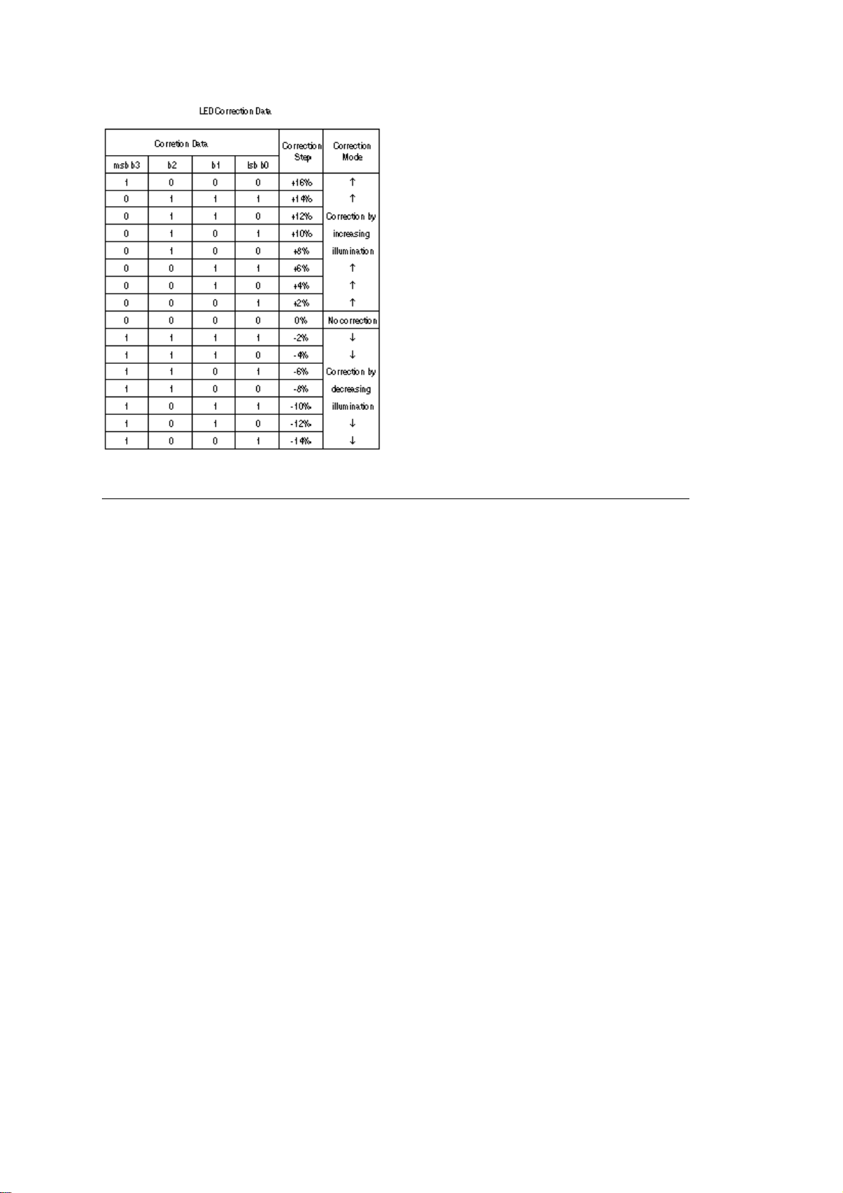
The LED driver (MSM6731BWAF) corrects the LED illumination by controlling the LED current. The LED
illumination can be set in 16 steps, with 7 steps in the direction of illumination increase in relation to the
standard value, and 8 steps in the direction of decrease. For this reason, the LED correction data is a
4-bit data for each dot.
The relationship between the LED correction data and LED current correction steps with the LED driver
(MSM6731BWAF) used in an LED head is shown below.
Page 27
Page 28

%2.4 Paper Jam Detection
2.4 Paper Jam Detection
The paper jam detection function monitors the paper condition when the power is turned on and during
printing. When any of the following conditions arises, this function interrupts the printing process. If any of
the following errors is encountered, printing can be recovered by removing the jammed paper (by opening
the upper cover, removing the jammed paper and closing the upper cover).
Error Cause of error
Paper input jam - The paper is in contact with the inlet sensor when the
power is turned on.
- After hopping operation is attempted three times, the
leading edge of the paper does not reach the inlet sensor.
Paper feed jam - The paper is in contact with the paper sensor when the
power is turned on.
- The leading edge of the paper does not reach the paper
sensor within a predetermined feeding distance since the
paper has reached the inlet sensor.
- The trailing edge of the paper does not pass over the
paper sensor within a predetermined feeding distance after
the same has passed over the inlet sensor.
- The leading edge of paper does not reach the outlet
sensor within a predeter-mined feeding distance after the
paper has reached the paper sensor.
Paper exit jam - The paper is in contact with the outlet sensor when the
power is turned on.
- The paper does not pass over the outlet sensor within a
predetermined feeding distance after the leading edge of
the paper has reached the outlet sensor.
- The paper size check for manual feeding finds that the
paper size is free size.
Paper size error Paper size error - The size of the paper is monitored by the
inlet sensor 1. The paper is not detected by the inlet sensor
1 within predetermined feeding distance.
- The inlet sensor 2 detects that the size of the loaded
paper is A4 or larger, or smaller than A4. The detected
paper size differs from the paper size set by command or
menu.
- The paper size check for manual feeding finds that the
paper size is free size.
Page 29
Paper Feed Check List
ERROR
Type of error Monitor Standard value Pluse Minus
Paper feed
error
Paper feed jam In sensor on
Paper feed jam Write sensor on
Paper size error In sensor on
Paper exit jam Out sensor on
Paper feed jam In sensor off
Note: Hyphen "-" in the table represents "not checked."Paper Length List
Hopping start
to
In sensor on
to
Write sensor on
to
Out sensor on
to
Out sensor on
to
Out sensor off
to
Write sensor off
72.0 36.0 _
20.0 20.0 _
138.0 69.0 _
Depends on the paper
length
Depends on the paper
length
22.0 22.0 -
45.0 45.0
45.0 45.0
Unit : mm
Type Paper length Min. Max.
A4 297.0 252.0 342.0
A5 210.0 165.0 255.0
B5 257.0 212.0 302.0
Check range
Page 30

LETTER 279.4 234.4 324.4
LEGAL 13 330.2 285.2 400.6
LEGAL 14 355.6 285.2 400.6
EXEC 266.7 221.7 311.7
A6 148.0 103.0 193.0
Monarch 190.5 145.5 235.5
COM-9 225.4 180.4 270.4
COM-10 241.3 196.3 286.3
DL 220.0 175.0 265.0
C5 229.0 184.0 274.0
Free 148.0 ~ 355.6 103.0 400.6
Unit : mm
Page 31

%2.5 Cover Open
2.5 Cover Open
When the stacker cover is opened, the cover open microswitch on the power supply/sensor board is
turned off to cut +5V supply to the high voltage power supply circuit. This results in the interruption of all
high-voltage outputs. At the same time, the CVOPN signal is sent to the main control board to notify that
the microswitch is off, and the main control board carries out the cover open process.
Page 32

%2.6 Toner Low Detection
2.6 Toner Low Detection
- Device The Toner Low Detection device consists of a stirring gear which rotates at a constant
rate, a stirring bar and a magnet on the stirring bar. The stirring bar rotation is driven by the link to
the gouged portion in the stirring gear.
- Operation Toner Low is detected by monitoring the time interval of the encounter of the magnet set on
the sensor plate and the magnet on the stirring bar.
Operation during Toner Full state
- The stirring bar rotates due to the mechanical transmission of energy originating from the interlocking
with the stirring gear.
- Even when the magnet on the stirring bar reaches the maximum height, the stirring bar is pushed by the
stirring gear, since the other side is being dipped in the toner.
Operation during Toner Low state
- When the stirring bar reaches the maximum height, it falls to the minimum height due to its own weight,
since there is no resistance pro-vided by the toner on the other side. Because of this, the time interval
during which it is in encounter with the magnet of the sensor plate becomes longer. By monitoring this
time inter-val, Toner Low state can be detected.
Page 33

TONER FULL state
TONER LOW state
- When the Toner Low state is detected 2 times consecutively, Toner Low is established.
- When the Toner Full state is detected 2 times consecutively, Toner Low is cancelled.
- When there is no change with the toner sensor for 2 cycles (3.25 sec. x 2) or more, then the
Toner Sensor Alarm is activated.
- The toner sensor is not monitored while the main (drum) motor is in a halt.
Page 34

Chapter 3
Parts Replacement
PARTS REPLACEMENT
The section explains the procedures for replacement of parts, assemblies, and units in the field. Only the
disassembly procedures are explained here. For reassembly, reverse the disassembly procedure.
Page 35

%3.1 Precautions for Parts Replacement
3.1 Precautions for Parts Replacement
(1) Before starting to replace parts, remove the AC cord and interface cable.
(a) Remove the AC cord in the following sequence:
i) Turn off (•o•) the power switch of the printer
ii) Disconnect the AC inlet plug of the AC cord from the AC receptacle.
iii) Disconnect the AC cord and interface cable from the printer.
(b) Reconnect the printer in the following procedure.
i) Connect the AC cord and interface cable to the printer.
ii) Connect the AC inlet plug to the AC receptacle.
iii) Turn on (•l•) the power switch of the printer.
(2) Do not disassemble the printer as long as it is operating normally.
(3) Do not remove parts which do not have to be touched; try to keep the disassembly to a
minimum.
(4) Use specified service tools.
(5) When disassembling, follow the laid out sequences. Parts may be damaged if these sequences
are not followed.
(6) Since screws, collars and other small parts are likely to be lost, they should temporarily be
attached to the original positions during disassembly.
(7) When handling ICs such as microprocessors, ROMs and RAMs, or circuit boards, use proper
anti-static procedures.
(8) Do not place printed circuit boards directly on the equipment or floor.
[Service Tools]
The tools required for field replacement of printed circuit boards, assemblies and units are listed in Table
3-1.
Table 3-1 Service Tools
Page 36

Page 37

%3.2 Parts Layout
3.2 Parts Layout
This section explains the layout of main components of the equipment.
[Lower base unit]
[Upper cover unit]
Page 38

[Base unit]
Page 39

Page 40

%3.3 How to Change Parts
3.3 How to Change Parts
This section explains how to change parts and assemblies listed in the disassembly diagram below.
In the parts replacement procedure, those parts marked with the part number inside l with white letters
are RSPL parts.
Page 41

%3.3.1 Upper Cover Assy
3.3.1 Upper Cover Assy
(1) With the power switch turned off, unplug the AC power cord from the outlet.
(2) Disconnect the interface cable 1.
(3) Open the IC card cover 2, and remove the IC card (option) 3.
(4) Press the knobs 4 on left and right sides and open the stacker cover assy 5.
(5) Take out the image drum unit 6.
(6) Remove two screws 7, and open the manual feed guide assy 8. Lift the front side of the upper cover 9
up and unlock the latches at two locations on the back side. Lift and remove the upper cover assy 9.
Notes :
1. When removing or reinstalling the upper cover, be careful not to get the motor cables tangled or
caught.
2. When reinstalling the screws 7, be sure to direct the screws into preexisting threads.
Page 42

%3.3.2 IC Card Cover
3.3.2 IC Card Cover
(1) Open the IC card cover 1, presss it from both sides at the hinges in the directions of arrows shown
below and remove it.
Page 43

%3.3.3 LED Head
3.3.3 LED Head
(1) Press the buttons on the left and right sides of the stacker cover 1 and open assy.
(2) Open the hook section on the left side of the stacker cover and remove the LED head 2.
Note: • Be sure not to touch directly or push on the SLA part of the LED head.
(3) Remove the PC Connector 4 from the LED Head. Do not remove the LED cable 3 from the PC
connector.
(4) After mounting the new LED head, re-attach the PC Connector and LED cable.
Note: • Set the drive time of the LED head according to the marking on the LED head (see 4.2.1).
Page 44

%3.3.4 Operator Panel Assy
3.3.4 Operator Panel Assy
(1) Use a flat blade screwdriver to unlock the two latches on the Operator Panel from the rear. Lift the
operator panel assy 1 from the back and remove it. NOTE: Use great care as the Operator Panel cable is
very short and can be easily damaged.
(2) Remove the Sumi card (operator panel cable) 2 from the connector (CN1) 3.
Note : You can remove the operator panel assy while the upper cover remains installed on the unit.
Page 45

%3.3.5 Pulse Motor (Main/Drum)
3.3.5 Pulse Motor (Main/Drum)
(1) Remove the Operator Panel (see 3.3.4)
(2) Remove the upper cover assy (see 3.3.1).
(3) Remove the connector 3 from the connector (DM) 2 of the TQCA-PCB 1.
(4) Remove two screws 4 and remove the pulse motor (main/drum) 6 from the motor bracket 5.
NOTE: To ease access to the bottom screw holding the motor(s) to the bracket, loosen the screws
holding the right side of the base unit.
Page 46

%3.3.6 Pulse Motor (Registration)
3.3.6 Pulse Motor (Registration)
(1) Remove the Operator Panel (see 3.3.4)
(2) Remove the upper cover assy (see 3.3.1).
(3) Remove the connector 3 from the connector (RM) 2 of the TQCA-PCB 1.
(4) Remove two screws 4 and remove the pluse motor (registration) 6 from the motor bracket 5.
NOTE: To ease access to the bottom screw holding the motor(s) to the bracket, loosen the screws
holding the right side of the base unit.
Page 47

%3.3.7 Face Up Stacker Assy
3.3.7 Face Up Stacker Assy
(1) Remove the operator panel assy (3.3.4).
(2) Remove the upper cover assy (see 3.3.1).
(3) Remove the screw 1 and remove the Sumi card (operator panel cable) 2 off the latch section of
face up stacker 4. Remove both the shield plate 3 and face up stacker 4 together.
(4) Unlock the latches at two locations, and remove the face up stacker 4.
Page 48

%3.3.8 Lower Base Unit
3.3.8 Lower Base Unit
(1) Remove the operator panel assy (see 3.3.4).
(2) Remove the upper cover assy (see 3.3.1).
(3) Remove the face up stacker assy (see 3.3.7).
(4) Remove the connecting cables 2 and 3 of the pulse motors from the connectors (DM, RM) of the
TQCA-PCB 1. NOTE: Mark the cables with the correct re-installation order and location to ease
re-assembly.
(5) Remove the LED head cables 4 and 5 from the connectors (HEAD1, HEAD2).
(6) Open the manual feed guide assy, remove seven screws 7, then remove the lower base unit
Page 49

%3.3.9 Eject Roller Assy
3.3.9 Eject Roller Assy
(1) Remove the operator panel assy (see 3.3.4).
(2) Remove the upper cover assy (see 3.3.1).
(3) Remove the face up stacker assy (see 3.3.7).
(4) Remove the lower base unit (see 3.3.8).
(5) Disengage the eject roller assy 1 from the lower base 2 by pressing the latch section of the eject
roller assy 1 in the direction of the arrow shown below, and remove the eject roller assy 1.
Page 50

%3.3.10 Motor Assy
3.3.10 Motor Assy
(1) Remove the operator panel assy (see 3.3.4).
(2) Remove the upper cover assy (see 3.3.1).
(3) Remove the face up stacker assy (see 3.3.7).
(4) Remove the lower base unit (see 3.3.8).
(5) Stand the lower base unit on its side as shown, and unlock two latches, then remove the motor
assy 1. NOTE: Use care as the gears are not permanently mounted onto the mounts/ shafts.
Mark and remove motor cables making careful note of orientation and placement.
Page 51

%3.3.11 Hopping Roller Shaft Assy
3.3.11 Hopping Roller Shaft Assy
(1) Remove the operator panel assy (see 3.3.4).
(2) Remove the upper cover (see 3.3.1).
(3) Remove the face up stacker assy (see 3.3.7).
(4) Remove the lower base unit (see 3.3.8).
(5) Remove the motor assy (see 3.3.10).
(6) With the lower base unit 1 standing on its side, remove the hopping roller gear 2 and the bearing
(A) 3.
(7) Remove the hopping roller shaft assy 4 (the bearing (B) 5 comes off, so be careful not to lose it).
Page 52

%3.3.12 Stacker Cover Assy
3.3.12 Stacker Cover Assy
(1) Remove the operator panel assy (see 3.3.4).
(2) Remove the upper cover assy (see 3.3.1).
(3) Remove the face up stacker assy (see 3.3.7).
(4) Release the stacker cover assembly from the reset Lever R 1 by gently prying the cover from
the reset lever. Remove the reset lever R 1 from the machine.
(5) Release the stacker cover assembly from the reset Lever L. Detach the reset spring 2 from the
lower base unit 3, turn the reset lever L 4 in the direction of arrow until it stops, and remove it in
the direction of arrow .
(6) Remove the LED Cable from the connector on the Main Logic Board. Unlock the two posts of
the lower base unit 3, then remove the stacker cover assy 5.
Note : Use care when removing the Stacker Cover Assembly as the cover close damper is not
permanently attached.
Page 53

%3.3.13 Registration Roller
3.3.13 Registration Roller
(1) Remove the operator panel assy (see 3.3.4).
(2) Remove the upper cover (see 3.3.1).
(3) Remove the face up stacker assy (see 3.3.7).
(4) Remove the lower base unit (see 3.3.8).
(5) Remove the motor assy (see 3.3.10).
(6) With the lower base unit standing on its side, remove the Registration Roller gear 1.
(7) Press the registration roller 2 in the direction of arrow and lift up the left side of it, then remove
the registration roller 2 and the bearing (registration) 3.
(8) Pull out the registration roller 2 in the direction of arrow B.
Page 54

%3.3.14 Transfer Roller
3.3.14 Transfer Roller
Special Note: Handling the Transfer Roller un-necessarily will cause poor print quality. Do not touch the
surface of roller.
(1) With the power switch turned off, unplug the AC cord from the outlet.
(2) Open the stacker cover.
(3) Release the transfer roller gear 1 by unlocking the latch of the main unit (never apply excessive
force when unlocking the latch).
(4) Lift the right side of the transfer roller 2, and shift it to the right side, then pull it out from the main
unit (at this time, the bearings 3 of the left and right sides of the transfer roller 2 will come off
also). NOTE: Use great care. The bearings are not permanently attached.
Page 55

%3.3.15 Fusing Unit
3.3.15 Fusing Unit
(1) Remove the operator panel assy (see 3.3.4).
(2) Remove the upper cover (see 3.3.1).
(3) Remove the face up stacker assy (see 3.3.7).
(4) Remove the stacker cover assy (see 3.3.12).
(5) Remove four screws 1, lift and remove the fusing unit 2.
Caution: Fusing unit may be hot. Use care when handling.
Notes :
1. When reinstalling or removing the fusing unit, tighten or loosen the screws while holding the
fusing unit assy 2 down with your hand (it is being pushed up by the fuser pressure roller).
2. When reinstalling the screws 1, be sure to direct the screws into preexisting thread and avoid
damaging the threads.
3. Do not apply excessive torque when tightening the screws 1. Stripping these screws will require
replacing the entire lower base unit.
Page 56

%3.3.16 Back-up Roller
3.3.16 Back-up Roller
(1) Remove the fusing unit assy (see 3.3.15).
(2) Remove the Lower Base Unit Assembly (see 3.3.8)
(3) Remove the Motor Assembly (see 3.3.10)
(4) Remove the Reset Lever R (see 3.3.12)
(5) Lift the left side of the back-up roller 1, and pull it out to the left side (at this time, two bushings
(back-up) 2 and the bias springs (back-up) 3 will also come off).
Page 57

%3.3.17 Sensor Plate (Inlet)
3.3.17 Sensor Plate (Inlet)
(1) Remove the operator panel assy (see 3.3.4).
(2) Remove the upper cover (see 3.3.1).
(3) Remove the face up stacker assy (see 3.3.7).
(4) Remove the lower base unit (see 3.3.8).
(5) Press the clamps of three sensor plates (inlet and paper) 1, and remove them by pressing them
upward from the bottom.
Page 58

%3.3.18 Sensor Plate (Outlet)
3.3.18 Sensor Plate (Outlet)
(1) Remove the operator panel assy (see 3.3.4).
(2) Remove the upper cover assy (see 3.3.1).
(3) Remove the eject roller assy (see 3.3.9).
(4) Remove the face up stacker assy (see 3.3.7).
(5) Remove the lower base unit (see 3.3.8).
(6) Remove the fusing unit assy (see 3.3.15).
(7) Press the clamps of the sensor plate (outlet) 1, and remove the sensor plate by pushing it up.
NOTE: This is a two part sensor. Use great care when handling.
Page 59

%3.3.19 Manual Feed Guide Assy
3.3.19 Manual Feed Guide Assy
(1) Remove the Operator Panel Assembly (see 3.3.4)
(2) Remove the upper cover assy (see 3.3.1).
(3) Open the manual feed guide assy 1, and release the engagement on both sides with the main
unit by carefully bending the manual feed guide assy 1.
Page 60

%3.3.20 Sensor Plate (Paper Supply)
3.3.20 Sensor Plate (Paper Supply)
(1) Remove the operator panel assy (see 3.3.4).
(2) Remove the upper cover assy (see 3.3.1).
(3) Remove the face up stacker assy (see 3.3.7).
(4) Remove the lower base unit (see 3.3.8).
(5) Press the clamps of the sensor plate (paper supply) 1 to unlock the latch, and remove it from
Note : When remounting, verify the proper the engagements as shown in the diagram.
Page 61

%3.3.21 TQCB-PCB
3.3.21 TQCB-PCB
(1) Remove the operator panel assy (see 3.3.4).
(2) Remove the upper cover assy (see 3.3.1).
(3) Remove the face up stacker assy (see 3.3.7), and shield plate.
(4) Remove the connector (PSIZE) (2NDTRAY) 5 and 6, LED Head cables, and motor connectors.
(5) Remove three screws 1.
(6) Move the TQCB-PCB 2 in the direction of arrow to disconnect it from the power supply/sensor
board 3.
(7) Remove the TQCB-PCB 2, together with the PCB guide plate (remove the fan motor 4 at the
same time).
(8) Remove the connector CN1, and disconnect the fan motor 4.
(9) Remove three screws 8 and two nuts 9, and remove the PCB guide plate 7 from the TQCB-PCB
2.
Note : When reinstalling the TQCB-PCB 2 onto the base plate 7, be careful not to bend the base plate (it
is desirable to place a block underneath it to prevent bending).
Page 62

%3.3.22 Transformer
3.3.22 Transformer
(1) Remove the operator panel assy (see 3.3.4).
(2) Remove the upper cover assy (see 3.3.1).
(3) Remove the face up stacker assy (see 3.3.7).
(4) Remove the connectors (CN1 and CN2).
(5) Remove two screws 1, and remove the transformer 2.
Note : When reinstalling the transformer, be sure to lay the AC and transformers primary side
cables under the divider (see view A diagram below)
.
Page 63

Page 64

%3.3.23 Power Supply/Sensor Board and Contact Assy
3.3.23 Power Supply/Sensor Board and Contact Assy
(1) Remove the Operator Panel assembly (3.3.4), then remove the upper cover assy (see 3.3.1).
(2) Remove the lower base unit (see 3.3.8).
(3) Remove the TQCA-PCB (See 3.3.21).
(4) Remove the transformer (see 3.3.22).
(5) Remove the AC inlet 1 from the base plate 2.
(6) Remove the screw 4 and remove the grounding (earth) wire 5.
(7) Remove three screws 6, and remove the power supply/sensor board 7 and contact assy 8
together.
(8) Unlock two latches 9, and remove contact assy 8 from the power supply/sensor board 7.
Notes :
1. Be careful about the sensor (paper supply) when reinstalling the lower base.
2. Make sure that no excessive force is applied to the power supply switch.
3. When installing the power supply/sensor onto the base plate, be careful not to bend the base
plate (it is desirable to place a block underneath it to prevent bending).
Page 65

%3.3.24 Cassette Guide L Assy
3.3.24 Cassette Guide L Assy
(1) Remove the paper cassette.
(2) Remove the Operator Panel Assembly (3.3.4), then remove the upper cover assy (see 3.3.1).
(3) Remove the lower base unit (see 3.3.8).
(4) Remove the TQCA-PCB (see 3.3.22).
(5) Remove the transformer (see 3.3.23).
(6) Remove the power supply/sensor board (see 3.3.24).
(7) Remove two screws 1, and remove the guide rails 2.
(8) Remove the screw 3, and remove the cassette guide L 9 by shifting it in the direction of the
arrow as shown below.
(9) Remove cassette lock lever 4 and torsion spring 5.
(10) Remove cassette lock lever spring 8 then remove the sheet link (L) 6 and link pull lock 7.
Special Note: The serial number sticker is attached to the Cassette Guide Right, Assembly. The serial
number sticker must be transfered from the old assembly to the new one.
Page 66

%3.3.25 Cassette Guide R Assy
3.3.25 Cassette Guide R Assy
(1) Remove the paper cassette.
(2) Remove the Operator Panel Assembly (3.3.4), then remove the upper cover assy (see 3.3.1).
(3) Remove the lower base unit (see 3.3.8).
(4) Remove the TQCA-PCB (see 3.3.22).
(5) Remove two screws 1, and remove the guide rails 2.
(6) Remove the screw 3, and remove the cassette guide R 4 by shifting it in the direction of arrow.
(7) Remove the cassette lock lever 5 and torsion spring 6.
(8) Remove the cassette lock lever spring 9, then remove the sheet link (R) 7 and link pull block 8.
(9) Remove two screws 0, and remove the square-shaped connector A.
Page 67

Chapter 4
%Adjustment
ADJUSTMENT
This chapter provides explanations concerning the adjustment necessary when replacing a part. The
adjustment is made by changing the parameter value set in EEPROM on the main control board. The
parameter can be set by the key operation from the operator panel. This printer has three kinds of
maintenance modes, and it is necessary to select one of the modes when replacing any parts.
Page 68

%4.1.1 User Maintenance Mode
4.1.1 User Maintenance Mode
To enter into the user maintenance mode, turn the POWER switch on while holding the MENU key down.
Function
There are five functions as follows:
- Menu reset
- Opepane menu disable
- Hex dump
- X-adjust / Y-adjust
- Drum counter reset
Detailed descriptions of these functions are provided in Appendix D, DIAGNOSTICS TEST.
Page 69

%4.1.2 System Maintenance Mode
4.1.2 System Maintenance Mode
Note: This mode is used only by maintenance personnel and it should not be released to the end-users.
To enter into the system maintenance mode, turn the POWER switch on while holding the Recover key
down.
Function
There are six functions as follows:
- Page count display
- Loop test
- Page count printing enable/disable
- EEPROM reset
- Rolling ASCII continues printing
- Hiper Windows display
Detailed descriptions of these functions are provided in Appendix D, DIAGNOSTICS TEST.
Page 70

%4.1.3 Engine Maintenance Mode
4.1.3 Engine Maintenance Mode
Note: This mode is used only by maintenance personnel, and it should not be released to the end users.
(1) To enter into the engine maintenance mode, turn the power on while holding ENTER and FORM
FEED keys down.
(2) Functions of this mode are selected by the menu.
(3) The way to exit out of this mode varies depending on the settings.
(4) There are following engine maintenance modes:
a) Head drive time setting Sets the drive time of the LED head.
b) Head width setting Sets the width of the LED head (39 or 40 chips).
c) Printing start position setting Sets the starting position of printing.
d) Drum count total display The total drum rotation count of the printer, as counted by the
engine section, is displayed on the LCD.
e) Drum count display The total image drum rotation count, as counted by the engine section, is
displayed on the LCD.
f) Standard tray paper feeding quantity setting Sets the amount of paper to be fed from the
standard tray.
g) High Capacity Second Paper Feeder paper feeding quantity setting Sets the amount of paper
to be fed from High Capacity Second Paper Feeder.
h) High Capacity Second Paper Feeder downloading table selection Selects the downloading
table of High Capacity Second Paper Feeder.
i) Power Envelope Feeder paper feeding quantity setting Sets the amount of paper to be fed
from Power Envelope Feeder.
j) Power Envelope Feeder downloading table selection Selects the downloading table of Power
Envelope Feeder.
k) Engine Reset All EEPROM areas used by the engine section are reset to factory default
values. The followings, however, are not reset:
- Menu Level-1
- Menu Level-2
- Operator Panel Menu Disable/Enable
- LED HEAD No.
- LED HEAD WID
- Page Print Disable/Enable
After reset, the printer returns to normal operating mode.
Note: "Printing start position setting" is for shipping. Do not change its default value.
Detailed descriptions of these functions are porvided in Appendix D, DIAGNOSTICS TEST.
Page 71

%4.1.4 EEPROM initialization
4.1.4 EEPROM initialization
The corresponding are of the EEPROM is initialized for each event as shown Table 4-1.
Page 72

%4.2 Adjustment When Replacing a Part
4.2 Adjustment When Replacing a Part
Adjustment is necessary when replacing any of the following parts.
Part Replaced
LED Head Set the LED head drive time.
Image Drum Cartridge Reset the image drum counter (refer to User's manual).
Adjustment
Page 73

%%4.2.1 Setting of LED Head Drive Time
4.2.1 Setting of LED Head Drive Time
Note: When the luminous intensity marking of the replacement LED head (new part) is same as that of
the removed LED head (old part), do not reset the LED head drive time.
Luminous Intensity Marking Label
Setting of LED Head Drive Time
Drive time of the LED head is set by setting the parameter of drive time of EEPROM according to the
luminous intensity marking on the LED head.
a. Corresponding table of luminous intensity marking and drive time parameter
Luminous intensity
marking on LED head
027 ~ 028 28
029 ~ 030 27
031 ~ 032 26
033 ~ 035 25
036 ~ 037 24
Drive time parameter
Page 74

038 ~ 040 23
041 ~ 043 22
044 ~ 046 21
047 ~ 049 20
050 ~ 052 19
053 ~ 057 18
058 ~ 060 17
061 ~ 064 16
065 ~ 069 15
070 ~ 073 14
074 ~ 079 13
080 ~ 084 12
085 ~ 090 11
091 ~ 096 10
097 ~ 103 9
104 ~ 110 8
111 ~ 118 7
119 ~ 126 6
127 ~ 135 5
136 ~ 144 4
145 ~ 154 3
b. Setting
Example: Method for setting the parameter to 19 (for a case where the previous parameter setting was
8).
Page 75

Page 76

Chapter 5
%5.1 Periodical Replacement Parts
5.1 Periodical Replacement Parts
The parts are to be replaced periodically as specified below:
Part name Condition for
replacement
Toner cartridge About 2,000 sheets of
paper have been
printed.
Image drum cartridge About 20,000 sheets
of paper have been
printed.
Cleaning Remarks
LED head Consumables
Consumables
Page 77

%5.2 Cleaning
5.2 Cleaning
Remove any toner or dust accumulated inside the printer. Clean in and around the printer with a piece of
cloth when necessary. Use the handy cleaner (service tool) to clean inside the printer.
Note: Do not touch the image drum, LED lens array, or LED head connector block. Do not use any
solvents.
Page 78

%5.2.1 Cleaning of LED Lens Array
5.2.1 Cleaning of LED Lens Array
Clean the LED lens array or replace the toner cartridge when white lines or stripes (void, light printing)
are generated vertically down the page, as shown below.
Note: The LED lens array must be cleaned with an LED head cleaner. Led Lens cleaner pads are
included with replacement toner cartridges.
(1) Set the LED head cleaner to the LED lens array as shown in the figure, then slide the cleaner
back and forth several times to clean the head.
Note: Gently press the LED head cleaner onto the LED lens array.
(2) Throw the cleaner pad away.
Page 79

%Cleaning Page Function
Cleaning Page Function
There is a charge roller cleaning function with this printer, which can be executed by the user.
(1) While the printer is in off-line mode, press both the left and right arrow keys simultaneously for at
least 2 seconds. The printer enters the cleaning mode.
(2) The LCD displays "CLEANING" on the upper line, and on the lower line, "MANUAL LETTER
REQUEST" is displayed, scrolling one character width at a time from right to left "LETTER" on
the lower line may instead be "A4" depending on the printer designation. While the lower line
scrolls the message, the message on the upper line remains fixed in place.
When the above messages appear on the LCD, the user can verify that the printer has entered the
cleaning mode and that it is requesting insertion of a letter (or A4) size paper into the manual
feederslot.
(3) Insert a sheet of paper into the manual feeder slot.
(4) Toner attached to the image drum is transferred onto the inserted sheet, and the sheet is
ejected with the toner residues printed. While this process is going on, the LCD displays
"CLEANING PRINT" message.
(5) The printer returns to off-line mode.
Page 80

%5.3.1 Lubrication
Lubrication
5.3.1 General Information Lubrication should performed once a year or as needed.
Use Lithium Grease.
When applying the grease, do not over-lubricate.
Do NOT allow lubrication to contact the surface of any rollers or paper guides.
Lubricate the items listed in the table below.
Page 81

%6. Troubleshooting Procedures
6. TROUBLESHOOTING PROCEDURES
As always, whenever dealing with static sensitive devices use good anti-static procedures and practices.
Page 82

%6.1 Troubleshooting Tips
6.1 Troubleshooting Tips
(1) Check the Troubleshooting section in the Printer Handbook.
(2) Gather as much information about the situation as possible.
(3) Inspect the equipment under the conditions close to those in which the problem had occurred.
Page 83

%6.2 Points to Check before Correcting Image Problems
6.2 Points to Check before Correcting Image Problems
(1) Is the printer being run in proper ambient conditions?
(2) Are supplies (toner) and routine replacement part (image drum cartridge) being replaced
properly?
(3) Is the printing paper normal (acceptable quality)?
(4) Is the image drum cartridge being loaded properly?
Page 84

%6.3 Tips for Correcting Image Problems
6.3 Tips for Correcting Image Problems
(1) Do not touch, or bring foreign matter into contact with the surface of the image drum.
(2) Do not expose the image drum to direct sunlight.
(3) Use caution when handling the fusing unit as it attains very high temperatures during operation.
(4) Do not expose the image drum to light for longer than 5 minutes at room temperature.
Page 85

Chapter 6
%6.4 Preparation for Troubleshooting
6.4 Preparation for Troubleshooting
(1) Operator panel display
The operating status of the printer is displayed by the liquid crystal display (LCD) of the operator panel.
Take proper corrective action as directed by messages which are being displayed on the LCD.
Page 86

%6.5 Troubleshooting Flow
6.5 Troubleshooting Flow
Should there be a problem with the printer, carry out troubleshooting according to the following procedure
flow:
Page 87

%6.5.1 LCD status message/problem list
6.5.1 LCD status message/problem list
The status and problems which may be displayed by messages on the LCD are listed in Table 6-1.
Category LCD status message Problem or status Remedy
Controller
errors
An error occurred in the controller.
n = Exception Code aaaaaaa =
Error Address
Code(nn) Error
1 ~ 3 Reserved
D ~ F Reserved
4 Address Error Exception (Load
command, command fetch)
5 Address Error Exception (Store
command)
6 Bus Error Exception (Command
fetch)
7 Bus Error Exception (Load
command, store command)
8 System Call Extension
9 Break Point Exception
Normal operation cannot
be ensured. off, then back
on to restart.
If normal operation is not
recovered procedure,
replace the main control
board.
A Reserved Instruction Exception
B Coprocessor Unusable
Exception
C Arithmetic Overflow Exception
A checksum error occurred when a
card was inserted.
An error occurred in the controller. Turn the power off, then
Turn the power off, then
back on
If a card other than those
for OL series is being
inserted, no error is
displayed and the inserted
card is ignored.
back on.
If normal operation is not
recovered by this restart
procedure, use the
following actions.
Page 88

Code(nn) Error Remedy (nn)
Page 89

On A failure occurred in the
p
controller. n = Exception Code
Replace the main control
board.
10 An error was detected by
program ROM check.
20 An error was detected by font
ROM check.
30 An error was detected by
resident RAM check.
40 An error was detected by
EEPROM check.
50 An error was detected by
optional software ROM check.
60 An error was detected by
optional RAM check.
Replace the main control
board.
Replace the main control
board.
Replace the main control
board.
Replace the EEPROM or
main control
Check the optional
software ROM board for
tion or replace it.
- Check the optional RAM
board for proper
connection.
- Check the mounting
position of short plugs
and additional RAM chips
(see Section 7.4).
- Replace the optional
RAM board.
70 A failure occurred with the Fan
motor.
71 A failure occurred with the
fuser (timeout error etc.).
72 A failure occurred with the
fuser (thermistor open error).
73 A failure occurred with the
fuser (thermistor short error).
74 SSIO Error
- Check the fan motor for
proper connection and for
any presence of foreign
matter in the fan. See
Section 6.5. 2-6).
- Replace the fan or the
main control board.
See Section 6.5.2 - 4.
See Section 6.5.2 - 4.
See Section 6.5.2 - 4.
- Check the connection
between the main control
board and the power
supply/sensor board.
- Replace the main
control board or sensor
board.
80 I/F timeout occurred between
the main control board and the
operator panel.
81 I/F timeout occurred between
the main control board and the
o
tional tray (High Capacity
Check the operator panel
for proper connection.
- Replace the flexible
cable, operator panel or
main control board.
See Section 6.5.2 - 5.
Page 90

F6 IPT2 program error
F7 IPT1 program error
- Turn the power off, then
back on again.
- Replace the main
control board.
Page 91

Size error Loading of paper indicated by the
first line message is requested.
The paper size may be one of the
followings:
tray: TRAY1, TRAY2, FEEDER
Paper: LETTER, EXECUTIV,
LEGAL 14, LEGAL 13, A4 SIZE,
A5 SIZE, A6 SIZE, B5 SIZE,
COM-9, COM-10, MONARCH, DL
ENV, C5 ENV.
Load the requested paper
in the tray.
Optional
card error
Buffer
overflow
Manual loading of paper indicated
by the first line message is
Load the requested paper
in the manual tr
requested. The paper size one of
the followings:
LETTER, EXECUTIV, LEGAL 14,
LEGAL 13, A4 SIZE, A5 SIZE, A6
SIZE, B5 SIZE, FREE SIZE,
COM-10, MONARCH, DL ENV, C5
ENV
While the power was on, card was
inserted or removed.
- Turn the power off,
insert the card, then turn
the power back on to
recover from the error.
- Replace the card.
The receive buffer is overflowing. - Press the operator panel
RECOVER key on the
operator panel to release
the error display.
- Change the setting of
the host or printer so that
the host can detect the
busy status of the printer.
Resend the data from the
host to the printer.
- Replace the interface
cable or main control
board.
The page buffer is overflowing
because it received too much data
for printing on the page.
Macro buffer is overflowing.
The DLL buffer is overflowing.
The printer overrun because the
print data is too compli-cated to be
printed.
Daily status The printer is in the off-line mode.
The second line indicates the
emulation
emulate: HP4, AUT, PS2, WIN,
HEX
- Press the RECOVER
key to release the error
display. - Install
additional optional RAM
board or reduce the print
data.
- Press the RECOVER
key on the operator panel
to release the error
display.
- Simplify page data
formatting.
Normal operation.
Page 92

The printer is processing data in
the
on-line mode.
Ready ON: The data that is not
printed remains in the buffer.
Ready flashing: The printer is
receiving data.
emulate: HP4, AUT, PS2, WIN,
HEX
Normal operation.
All fonts of the printer are being
printed during self-test.
The current menu setting is being
printed.
Ready ON: Executed by
command entry.
Ready flashing: Executed by key
operation.
Message displayed when the
power is turned on. When the
power is turned on, the LEDs are
turned on for approxi-mately 1
second, conducting a test to verify
the conditions of the LEDs and
LCD.
Message displayed to indicate that
the controller is under-going an
initialization when the power is
turned on. This message is
displayed after the turning on of the
LEDs as described above.
Normal operation.
Normal operation.
Normal operation.
Message displayed to indicate that
in order to reflect the changes in
the menu to the editing
environment, RESET must be
executed.
This message is displayed when
the printer is unable to conduct
automatic reset due to the
existence of temporary attributes
such as DLL/Macro/User
Pattern/User Symbol Set.
Normal operation.
Page 93

Message displayed to indicate that
the change of emulation is taking
place.
This message is displayed when
the PostScript option board is
installed in the printer and the
following operations are carried
out:
(1) The emulation of the printer
language is changed in the menu
and then exit from the menu is
carried out.
(2) The emulation is switched by
command while the printer is in
on-line mode.
Normal operation.
The demo page is being printed.
Ready LED on: Executed by
command entry.
Ready LED blinking: Executed by
key operation.
When the number of copies being
printed is two or more, the number
of copies being printed is
displayed.
This message is displayed together
with another message on the first
line.
PostScript mode only.
This message is displayed when
ON LINE key is pressed while the
printer is processing a job, if the
JOB RESET menu is off.
The printer goes off-line after
completing the job.
Normal operation.
Normal operation.
This message is displayed when
the printer is performing the
cleaning print.
Normal operation.
Page 94

Manual loading of paper indicated
by the second line mes-sage is
being requested for cleaning. The
paper size (#) may be one of the
followings:
#: LETTER REQUEST, A4 SIZE
REQUEST
Normal operation.
PostScript mode only.
This message is displayed when
ON LINE key is pressed while the
printer is processing a job, if the
JOB RESET menu is on.
Even while this message is being
displayed, the printer continues to
process the job normally.
RESET TO FLUSH
(PS Only)
PostScript mode only.
This message is displayed during
cancelling of a job. The message
goes off when the job cancellation
is completed.
The data which remained unprinted
in the buffer is deleted and the
printer is initialized to user default
settings.
The temporary DLLs, macros and
user pattern are deleted.
- Press ON LINE key
again. The printer goes
back to on-line mode a
process the job.
- Press Reset key. The
job is cancelled.
Normal operation.
Normal operation.
This message is displayed when
the printer cannot reset
automatically to exit from the menu
because there are data and DLL's
and macros having temporary
attributes when the printer is
changed from set mode to another
mode.
Toner is running out.
This message is displayed together
with another message on the first
line.
Normal operation can be
continued.
Normal operation.
Replace the toner
cartridge.
Page 95

A fault occurred with the toner
sensor.
This message is displayed together
with another message on the first
line.
Normal operation can be
continued.
Replace the power
supply/sensor board.
This message is displayed together
with another message on the first
line.
Normal operation can be
continued.
Unavailable printer language was
designated by PJL com-mand
(warning).
The printer is in the power-saving
mode.
This message is displayed together
with another message on the first
line.
PostScript mode only.
This message appears when the
interpreter detects an error while a
job is being processed. The
remainder of the job is ignored.
- Replace the image drum
cartridge.
- After replacing the drum
cartridge, reset the drum
counter (refer to the
Printer Handbook).
- To clear, press Recover
key when "CLEARABLE
WARNINGS=ON" is
being selected in thE
MENU.
- Check the host program.
Normal operation.
- Check the printer setting
of the host.
- Check the printer job
data to see if there is any
unsupoorted or illegal
operation in the data.
PostScript mode only.
This message appears when the
toner sensor error is detected,
when the drum counter is under
30.
Replace the power
supply/sensor board.
Page 96

%6.5.2 LCD message troubleshooting
6.5.2 LCD message troubleshooting
If the problems cannot be corrected by using the LCD status message/problem list, follow the
troubleshooting flowcharts given here to deal with them.
Page 97

%1 Printer doesn't work normally after the power is turned on.
Page 98

Page 99

%2 - 1 Paper input jam
2 - 1 Paper input jam
Page 100

%2 - 2 Paper feed jam
2 - 2 Paper feed jam
 Loading...