

Page 1
OKI
®®
®
®®
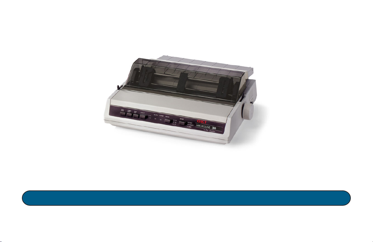
MICROLINE® 310
Printer Handbook
P/N 59342501
Page 2

Every effort has been made to ensure that the information
in this document is complete, accurate and up-to-date. Oki
Data assumes no responsibility for the results of errors
beyond its control. Oki Data also cannot guarantee that
changes in software and equipment made by other
manufacturers, and referred to in this handbook, will not
affect the applicability of the information in this manual.
Mention of software products manufactured by other
companies does not necessarily constitute endorsement by
Oki Data.
© 2002 by Oki Data.
Written and produced by the Oki Data Training and
Publications Department. Please address any comments on
this publication to:
Training & Publications Dept.
Oki Data Americas, Inc.
2000 Bishops Gate Blvd.
Mount Laurel, New Jersey 08054-4620
OKI, OKIDATA and MICROLINE are registered
trademarks of Oki Electric Industry Company, Ltd.
NERGY STA R is a registered trademark of the United States
E
Environmental Protection Agency.
Epson is a registered trademark of Seiko Epson
Corporation (SEC), registered in the U.S. and other
countries.
Microsoft and MS-DOS are registered trademarks and
Windows is a trademark of Microsoft Corporation in the
United States and other countries.
Year 2000 Compliance
All products currently sold by Oki Data are Year 2000
Compliant. Each product contains information technology
that accurately processes date and time data between the
years 1999 and 2000, and carries no issue for the
September 9, 1999 (9999) programming concern. These
products, when used in combination with products
purchased from other manufacturers, whose products
properly exchange data and time information, will
accurately process the date and time. All future products
are committed to meeting the same Year 2000 compliance.
ENERGY STAR
As an ENERGY STAR® Partner, Oki Data
has determined that this product meets
NERGY STA R guidelines for energy
the E
efficiency.
Page 3

Important Safety Instructions
Your OKI printer has been carefully designed to give you
years of safe, reliable performance. As with all electrical
equipment, there are a few basic precautions you should
take to avoid hurting yourself or damaging the printer:
• Carefully read all setup and operating instructions. Be
sure to save all documents for future reference.
• Read and follow all warning and instruction labels on
the printer itself.
• Place your printer on a firm, solid surface. If you put in
on something unsteady, it might fall and be damaged.
• Avoid overheating the printer. Do not place it on a soft
surface, such as a rug, sofa, or bed. The vents may be
blocked, causing the printer to overheat.
• The printer must be installed near a power outlet which
will remain easily accessible.
• Be certain that your power source matches the rating
listed on the back of the printer. If you aren’t sure,
check with your dealer or with your local power
company.
• Your printer has a grounded, 3-prong plug as a safety
feature. It will only fit into a grounded outlet. If you
can not plug it in, chances are that you have an older,
non-grounded outlet. Contact an electrician to have it
replaced with a grounded outlet. Do not use an adapter
to defeat the grounding.
• To avoid damaging the power cord, do not put anything
on it or place it where it will be walked on. If the cord
becomes damaged or frayed, replace it immediately.
Printer Handbook: English 3
|
Page 4

• If you’re using an extension cord or power strip with the
printer, make sure that the total of the amperes required
by all the equipment on the extension is less than the
extension’s rating. Generally, the total ratings of all
equipment plugged into any one power line should not
exceed 15 amperes. Don’t exceed this unless you know
that the power line your equipment is plugged into has a
rating above 15 amperes.
• Unplug the printer before you clean it. Use only a damp
cloth. Do not use liquid or aerosol cleaners.
• To protect your printer from overheating, make sure no
openings on the printer are blocked. Do not put the
printer on or near a heat source, such as a radiator or
heat register. If you put the printer in any kind of
enclosure, make sure it is well ventilated.
• The printhead can get quite hot when it has been
printing for a length of time. Do not touch the printhead
until it has had a chance to cool off.
• Do not use your printer near water. Do not spill liquid
of any kind into it.
• Do not poke anything into the ventilation slots on the
sides of the printer. You could get a shock or cause a
fire.
• Aside from the routine maintenance described in this
document, don’t try to service the printer yourself.
Opening the cover may expose you to shocks or other
hazards. Don’t make any adjustments other than those
outlined in the document. You might cause damage
requiring extensive repair work.
• If anything happens that indicates that your printer is
not working properly or has been damaged, unplug it
immediately and have your printer serviced.
These are some of the things to look for:
– The power cord or plug is frayed or damaged.
– Liquid has been spilled into the housing, or the
printer has been exposed to water.
– The printer has been dropped or its cabinet has
been damaged.
– The printer doesn’t function normally when you’re
following the operating instructions.
Safety4
|
Page 5

Table of Contents
Setting Up .............................................................6
Components .................................................................. 6
Remove the Shipping Materials ................................... 7
Install/Replace the Ribbon Cartridge ........................... 8
Install the Platen Knob ............................................... 10
Install the Paper Separator .......................................... 10
Install the Power Cord .................................................11
Connect To the Computer ............................................ 11
Load Paper .................................................................. 12
Loading Continuous Form Paper for Bottom Feed . 13
Loading Continuous Form Paper for Rear Feed ..... 16
Loading Single Sheets ............................................. 19
Run the Self Test......................................................... 20
Controlling the Printer...................................... 21
The Front Panel .......................................................... 21
Printer Driver .............................................................. 23
Appendix A: Replacement Parts ...................... 25
Appendix B: Control Circuit Board Switches 27
Appendix C: Specifications ............................... 29
Index ................................................................... 31
Printer Handbook: English 5
|
Page 6

Setting Up
Components
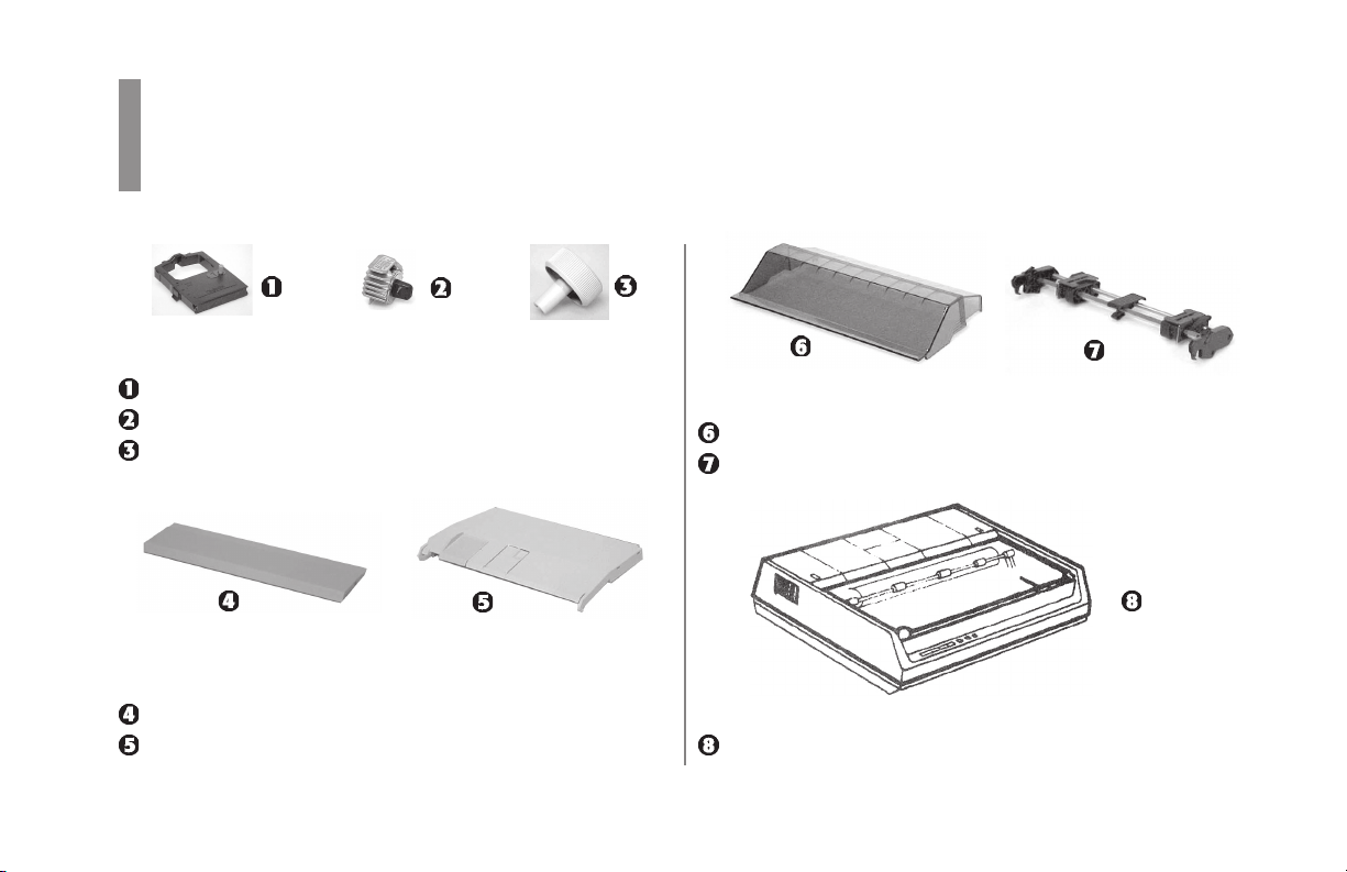
Unpack the box and check for the following:
✔ Interface cables and paper are sold separately.
ML310 Printer
Ribbon cartridge
Platen knob
6
|
Power cord
Paper separator
• Grounding screw (not illustrated: see “Connect to the
Computer” later in this section)
• CD (not illustrated)
✔ If any of these items is missing or damaged, see your
dealer for a replacement.
Page 7
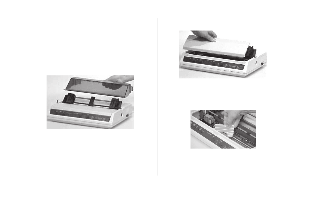
Remove the Shipping Materials
1 Remove any packing tape.
2 Check for a protective film on the front panel, and
remove it.
3 Lift off the acoustic cover.
4 Pull up on the access cover to unsnap it, then remove it.
5 Remove the shipping retainer that secures the printhead
during shipment. Save it in case you ever need to ship
the printer.
Printer Handbook: English 7
|
Page 8
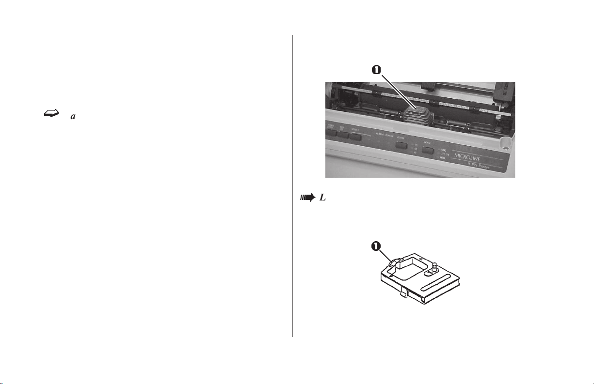
Install/Replace the Ribbon Cartridge
1 If necessary, lift off the acoustic cover and remove the
access cover.
ë
Caution! It is recommended that the printer be
switched off prior to removing the access cover. The
printhead can get very hot during extended periods
of printing—be sure to let it cool off before you
touch it.
2 Center the printhead (1) so that it’s away from the bail
rollers. Make sure the bail is closed (lever back).
Leave the clear plastic ribbon shield (1) on the
à
cartridge! Use only genuine Oki Data ribbon
cartridges.
Setting Up8
|
Page 9
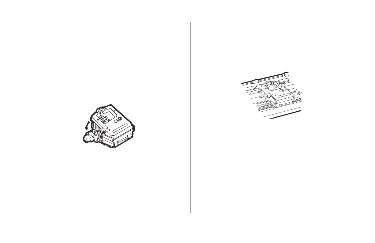
3 If you are replacing the ribbon cartridge, grasp the
sides of the cartridge at either side of the printhead
(Caution! printhead can be HOT!), then lift the used
cartridge out and discard it.
4 With the knob side up, tilt the new ribbon cartridge onto
the printhead plate so that it slides into the area of the
plate that is closest to the front of the printer, then lower
the ribbon shield over the printhead (Caution! Printhead
may be HOT!), aligning the tabs with the inserts on the
printhead plate.
✔ If the ribbon won’t load easily, turn the knob slightly
until the x-shaped notch on the bottom of the ribbon
cartridge aligns with the x-shaped insert on the ribbon
plate.
5 Press on the cartridge until you feel it snap into place.
6 If you are replacing the ribbon cartridge, put the access
cover back on and press down until it snaps into place,
then replace the acoustic cover.
Printer Handbook: English 9
|
Page 10
Install the Platen Knob
Install the Paper Separator
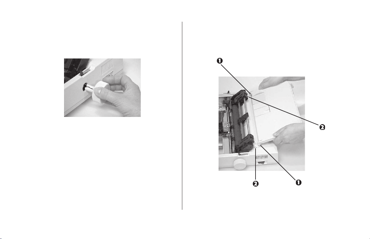
Insert the knob in the hole on the right side of the printer,
lining up the notch in the knob with the pin on the shaft.
Place the tabs (1) on the paper separator into the slots (2)
on the printer, then press down to snap it in place.
Setting Up10
|
Page 11

Install the Power Cord
Connect To the Computer
1 Make sure the printer is turned off.
2 Plug the power cord supplied with your printer into the
power socket (1).
The outlet voltage must match the voltage marked
à
on the printer label.
3 Plug the opposite end into a grounded outlet.
✔ The interface cable is not supplied with the printer.
1 Insert the plug into the parallel port on the back of the
printer (1) and secure it with the wire clips (2).
2 If necessary, use the grounding screw suplied with the
printer to attach the frame ground wire to the hole (3) at
the right of the parallel port.
3 Connect the other end of the cable to the computer.
4 Turn the printer on.
Printer Handbook: English 11
|
Page 12

Load Paper
✔ The maximum usable thickness of multi-part forms is
0.014 inch (0.36 mm).
Set the Printhead Gap Lever
Before you load continuous paper, be sure to set the blue
printhead gap lever (1) as follows:
• position 1 for 1- or 2-part paper
• position 2 for 3- or 4-part paper
• position 3 for 5-part, extra-thick paper.
Paper Lever Positions
= Continuous Forms
= Single Sheet
Bail Lever Positions
Open Closed
Setting Up12
|
Page 13

Loading Continuous Form Paper for Bottom Feed
1 Set the printer on a slotted printer stand (optional,
available from third party), aligning the opening in the
base of the printer with the slot on the stand.
2 Place the paper stack on the bottom of the printer stand.
✔
If the printer is on and selected (SELECT light on),
press the SELECT button to deselect it.
✔
If you are reloading paper, remove the acoustic cover
and the access cover.
3 Pull the paper lever (1) forward (continuous forms
position) and open the bail lever (2).
Printer Handbook: English 13
|
Page 14

4 Slide the paper through the opening in the base of the
printer, then push the paper lever (1) back (single sheet
position) and turn the platen knob (2) to move the paper
up level with the paper bail (3).
5 Pull the paper lever forward.
6 Pull up the lock levers (1) to release the tractors and
open the tractor covers (2).
✔
The pins (1) at either end of the platen are not used
with the pull tractor installed. Please leave them
locked in place.
Setting Up14
|
Page 15

7 Slide the tractors to align them with the edges of the
paper, then set the paper holes on the tractor pins (1).
Make sure the paper covers the groove on the left side
of the platen, then slide the tractor guide (2) to the
center of the paper.
8 Adjust the tractors so that the paper holes are centered
on the pins, then close the tractor covers.
9 Space the rollers on the paper bail evenly across the
paper, then close the bail lever.
10 Use the platen knob to advance the paper up to the
second sheet, then move the paper up to where you
want the first line of printing to begin (top of form).
The position you have selected will be set
automatically when you turn the printer on.
✔
If the printer is on, press the TOF SET button while
the printer is deselected (SELECT light off) to set
the position as the top of form.
11 Put the access cover back on and press down until it
snaps into place, then replace the acoustic cover.
Printer Handbook: English 15
|
Page 16
Loading Continuous Form Paper for Rear Feed
1 Place the paper stack behind the printer.
✔
If the printer is on and selected (SELECT light on),
press the SELECT button to deselect it.
✔
If you are reloading paper, remove the acoustic cover
and the access cover.
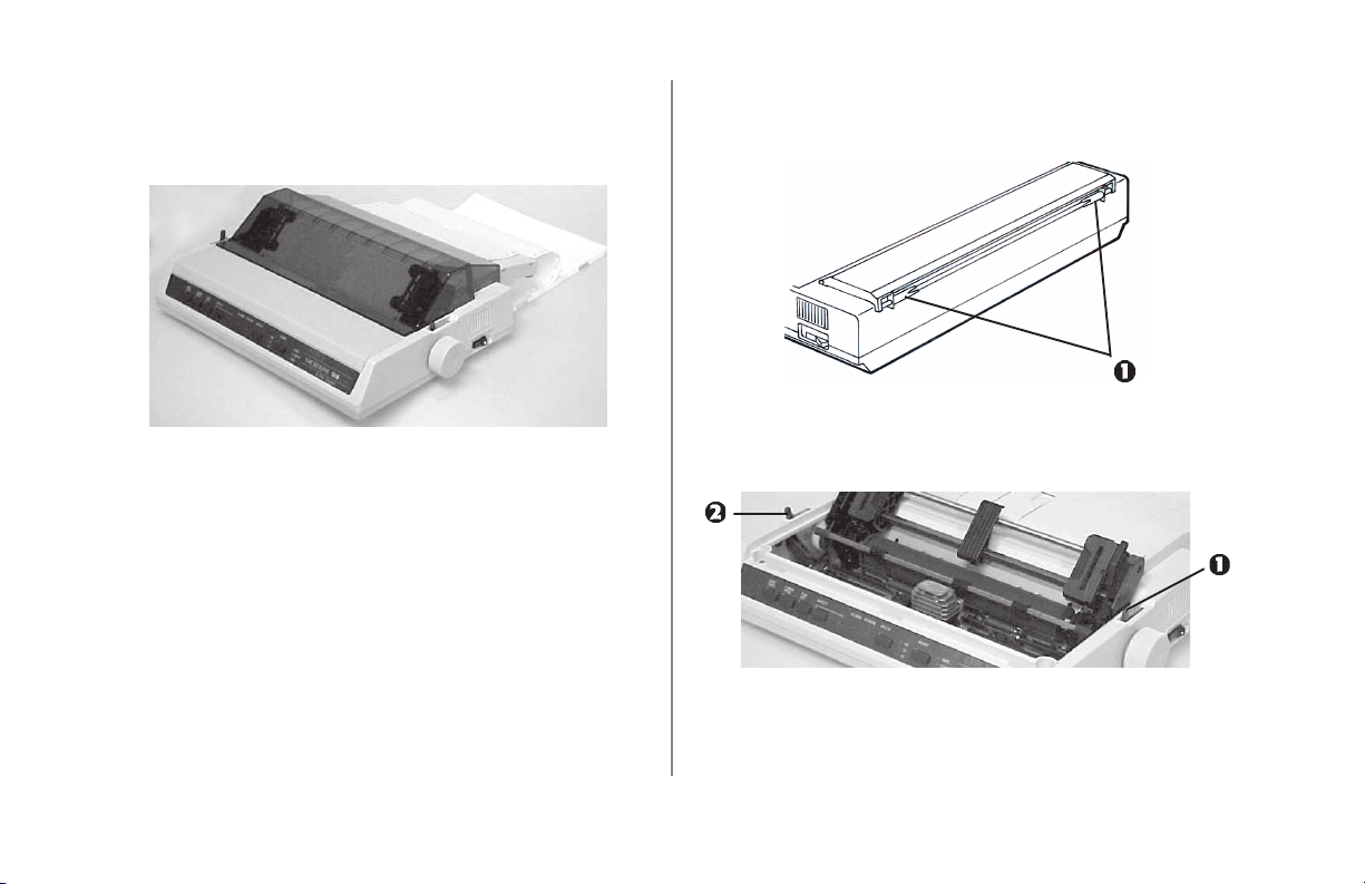
2 With the paper separator lying flat on the printer, slide
the guides (1) to their widest position.
3 Pull the paper lever (1) forward (continuous forms
position) and open the bail lever (2).
Setting Up16
|
Page 17

4 Insert the paper in the slot in the paper separator and
guide it into the printer underneath the platen.
5 Push the paper lever (1) back (single sheet position) and
turn the platen knob (2) to move the paper up level with
the paper bail (3).
6 Pull the paper lever forward.
Printer Handbook: English 17
|
Page 18

7 Pull up the lock levers (1) to release the tractors and
open the tractor covers (2).
✔
The pins (1) at either end of the platen are not used
with the pull tractor installed. Please leave them
locked in place.
8 Slide the tractors to align them with the edges of the
paper, then set the paper holes on the tractor pins (1).
Make sure the paper covers the groove on the left side
of the platen, then slide the tractor guide (2) to the
center of the paper.
9 Adjust the tractors so that the paper holes are centered
on the pins, then close the tractor covers.
ë
The paper may jam or cause other problems if it is
stretched too tightly or left too loose on the pins. If
the sprocket holes stretch or tear during printing,
readjust the pins.
Setting Up18
|
Page 19

10 Space the rollers on the paper bail evenly across the
paper, then close the bail lever.
11 Adjust the paper guides on the back of the paper
separator so that they are as close to the edges of the
paper as possible without touching it.
12 Use the platen knob to advance the paper up to the
second sheet, then move the paper up to where you
want the first line of printing to begin (top of form).
The position you have selected will be set
automatically when you turn the printer on.
✔
If the printer is on, press the TOF SET button while
the printer is deselected (SELECT light off) to set
the position as the top of form.
13 Put the access cover back on and press down until it
snaps into place, then replace the acoustic cover.
Loading Single Sheets
✔
If the printer is on and selected (SELECT light on),
press the SELECT button to deselect it.
1 Use the platen knob to remove any continuous forms
paper from the print path.
2 Remove the acoustic cover.
3 Raise the paper separator to the upright position, then
slide the guide (1) to the position marked for single
sheets (2).
Printer Handbook: English 19
|
Page 20

4 Push the paper lever back (single sheet position).
5 Insert a single sheet of paper.
6 Remove the access cover and open the bail lever.
7 Use the platen knob to wind the paper through to the
front of the printer, guiding it under the open bail, then
close the bail lever.
8 Use the platen knob to adjust the place on the sheet
where the first line of printing will begin (top of form).
The top of form you have selected will be set
automatically when you turn the printer on.
✔
If the printer is on, press the TOF SET button while
the printer is deselected (SELECT light off) to set
the position as the top of form.
9 Replace the access cover.
10 Press the SELECT button to reselect the printer (the
SELECT light will come on).
Switching Back to Continuous Forms
1 Open the bail lever and move the paper lever to the
continuous forms position.
2 Remove the printed sheet from the printer.
3 Load the continuous forms paper (see the appropriate
section under Load Paper in this manual).
Run the Self Test
Hold down the LINE FEED button while turning on the
printer.
✔ The first line of the self test contains information on the
version printer you’re using. If you should call for
information or service, please have a self-test printout
handy so that our customer Service Representative can
determine exactly what model printer you have.
Setting Up20
|
Page 21

Controlling the Printer
The Front Panel
LINE FEED button: moves the paper up one line at a
time.
FORM FEED button: moves the paper to the top
margin of the next page.
TOF SET button: sets the top margin at the current
position — the SELECT light ( ) must be off.
SELECT button: selects or deselects the printer.
SELECT light: shows whether the printer is ready to
receive data (on) or not (off).
ALARM light: indicates that paper is low or out, or that
there is an internal printer problem.
POWER light: indicates that the printer is plugged in
and turned on.
Printer Handbook: English 21
|
Page 22

The Front Panel (continued)
PITCH button: selects the size of the printed characters
— 10, 12, or 17 characters per inch (cpi), indicated by
the lights next to the button.
Controlling the Printer22
|
MODE button: selects the type of printing, indicated by
the lights next to the button:
• NLQ (Near Letter Quality): high-resolution printing
in two passes of the printhead; not available at 17
cpi.
• UTILITY: Normal printing.
• HSD (High-Speed Draft): fast printing for drafts;
underlining is the only printing feature available with
HSD.
Page 23

Printer Driver
The printer driver is in the Drivers folder on the CD
supplied with your printer.
To install the driver on Windows systems other
than Windows 3.1x
Use the Add Printer Wizard to install the driver:
1 Place the ML310 CD in your CD-ROM drive.
2 Click Start ® Settings ® Printers.
3 Click Add Printer.
The Add Printer Wizard appears.
4 Follow the on-screen instructions to load the driver.
5 When you get to the window which asks you to select
the manufacturer and model of your printer, click Have
Disk, then browse to the appropriate directory on the
CD and double click the inf file:
• For Windows XP:
\Drivers\Win XP\Oemprint.inf
• For Windows 2000
\Drivers\Win2k\Oemprint.inf
• For Windows Me
\Drivers\Win9xme\English\Oemprint.inf
• For Windows 98
\Drivers\Win9xme\English\Oemprint.inf
• For Windows 95
\Drivers\Win9xme\English\Oemprint.inf
• For Windows NT 4.0
\Drivers\WinNT40\English\Printer.inf
6 When you get back the the window asking for the
manufacturer and model: click Next to continue.
7 Follow the on-screen instructions to finish loading the
driver.
Printer Handbook: English 23
|
Page 24

To install the driver in Windows 3.1x
1 Place the ML310 CD in your CD-ROM drive.
2 In the Main window, double-click Control Panel.
3 Double click Printers.
4 Click Add.
5 Click Install.
6 Click Browse and go to the following directory on the
CD: \drivers\win31\english.
7 Click OK twice.
The Add Unlisted or Updated Printer dialog box
appears with OKI DATA ML310 listed.
8 Click OK
The ML310 appears in the Installed Printers box.
9 Click Setup and select Tractor under Paper Source,
then click OK.
10 To use a port other than LPT1:, click Connect and
select another port, then click OK.
11 With OKI DATA ML310 selected in the Installed
Printers box, click Set as Default Printer.
12 Click Close.
Controlling the Printer24
|
Page 25
Appendix A: Replacement Parts
Item OKI Number
Ribbon Cartridge ........................................... 52102001
Printhead........................................................ 50063802
Platen Knob ................................................... 40673402
Item OKI Number
Access Cover ................................................. 42178701
Paper Separator.............................................. 42017901
Item OKI Number
Acoustic Cover .............................................. 53450001
Pull Tractor .................................................... 50044701
Item OKI Number
Upper Cover .................................................. 42014601
Printer Handbook: English 25
|
Page 26

Item OKI Number
AC Cord, 120V ............................................. 56631801
✔
For 220V AC cords, contact your OKI dealer.
Item OKI Number
Fuses
1.5A Fuse (logic board)....................................... 56301701
1A Fuse (power board) ....................................... 56301501
Option
Roll Paper Stand Assembly................................. 70007701
Manual
Printer Handbook ................................................ 59342501
Replacement Parts26
|
Page 27

Appendix B: Control Circuit Board Switches
Switches
Language/Page Length 1, 2, 3 4, 5
USA English, 11" OFF, ON, OFF OFF, ON
French, 11 Inches ON, ON, OFF OFF, ON
German, 11 Inches OFF, OFF, ON OFF, ON
British, 11 Inches ON, OFF, ON OFF, ON
Danish 1, 11 Inches OFF, ON, ON OFF, ON
✔ Factory default settings are printed in bold italics.
Swedish 1, 11 Inches ON, ON, ON OFF, ON
Italian, 11 Inches OFF, OFF, OFF ON, ON
Spanish, 11 Inches ON, OFF, OFF ON, ON
Japanese, 11 Inches OFF, ON, OFF ON, ON
Norwegian, 11 Inches ON, ON, OFF ON, ON
Printer Handbook: English 27
|
Page 28

Switches (continued)
Switches
Language/Page Length 1, 2, 3 4, 5
Danish 2, 11 Inches OFF, OFF, ON ON, ON
Dutch, 11 Inches ON, OFF, ON ON, ON
Swedish 2, 11 Inches OFF, ON, ON ON, ON
Swedish 3, 11 Inches ON, ON, ON ON, ON
USA English, 12 Inches OFF, OFF, OFF OFF, OFF
French, 12 Inches ON, OFF, OFF OFF, OFF
German, 12 Inches OFF, ON, OFF OFF, OFF
British, 12 Inches ON, ON, OFF OFF, OFF
Danish 1, 12 Inches OFF, OFF, ON OFF, OFF
Swedish 1, 12 Inches ON, OFF, ON OFF, OFF
Italian, 12 Inches OFF, ON, ON OFF, OFF
Spanish, 12 Inches ON, ON, ON OFF, OFF
Japanese, 12 Inches OFF, OFF, OFF ON, OFF
Norwegian, 12 Inches ON, OFF, OFF ON, OFF
Danish 2, 12 Inches OFF, ON, OFF ON, OFF
Dutch, 12 Inches ON, ON, OFF ON, OFF
Swedish 2, 12 Inches OFF, OFF, ON ON, OFF
Switches
Language/Page Length 1, 2, 3 4, 5
Swedish 3, 12 Inches ON, OFF, ON ON, OFF
Swedish 4, 12 Inches OFF, ON, ON ON, OFF
Turkish, 12 Inches ON, ON, ON ON, OFF
Swiss 1, 12 Inches OFF, OFF, OFF OFF, ON
Swiss 2, 12 Inches ON, OFF, OFF OFF, ON
Auto LF Switch 6
Disengaged OFF
Engaged ON
Zero Character Switch 7
Unslahsed OFF
Slashed ON
Switch 8: Unused
Switches28
|
Page 29

Appendix C: Specifications
✔ Specifications subject to change without notice.
Print Speed
Utility: 200 cps @ 10, 12, 17.1, 20 cpi
100 cps @ 5, 6, 8.5 cpi
High Speed Draft: 240 cps @ 10 and 17.1 cpi
300 cps @ 12 cpi
NLQ: 50 cps @ 10, 12, 17.1, 20 cpi
25 cps @ 5, 6, 8.5 cpi
Emulation
Epson® ESC/P
Characters Per Line
at 10 cpi: 80
at 12 cpi: 96
at 17.1 cpi: 132
Electrical Characteristics
Voltage: 120V AC ±10%
or
220/240V AC ±10%
Printer Handbook: English 29
|
Page 30

Reliability
Mean Time Between
Failures (MTBF): 6000 hours at 25% duty cycle,
35% page density
Physical Dimensions
Size: 381 mm (15 inches) wide
378 mm (14.9 inches) deep
128 mm (5 inches) high
Mean Time To Repair
(MTTR): 15 minutes
Ribbon Life: 3 million characters
Printhead life: 400 million strokes per wire
Specifications30
|
Weight: 4.5 kg (10 lb.)
Paper Specifications
No. of copies: Original plus 4 copies
Basis Weight: 16 to 20 lb. (60 to 75 g/m
2
)
Page 31

Index
A
ALARM light .................................... 21
Auto line feed setting......................... 28
C
Components ......................................... 6
Computer connection ......................... 11
Connections
power.............................................. 11
Connections, computer ...................... 11
Control board circuit switches ..... 27–28
Control panel .............................. 21, 22
lights ........................................ 21, 22
D
Driver, printer .................................... 23
E
Electrical specifications ..................... 29
Emulation .......................................... 29
F
FORM FEED button .......................... 21
Front panel .................................. 21, 22
lights ........................................ 21, 22
Fuses, replacement............................. 26
H
HSD light ........................................... 22
L
Language setting ......................... 27, 28
Lever positions .................................. 12
Lever, printhead gap .......................... 12
LINE FEED button ............................ 21
Loading paper
bottom feed .............................. 13–15
rear feed ................................... 16–19
single sheets ............................. 19–31
M
MODE button .................................... 22
N
NLQ light........................................... 22
Printer Handbook: English 31
|
Page 32

P
R
T
Page length setting ...................... 27, 28
Paper, loading
bottom feed .............................. 13–15
rear feed ................................... 16–19
single sheets ............................. 19–31
Paper separator
installation ...................................... 10
Parts, replacement .............................. 25
PITCH button .................................... 22
Platen knob
installation ...................................... 10
replacement .................................... 25
POWER light ..................................... 21
Print speed ......................................... 29
Printer
dimensions ..................................... 30
driver .............................................. 23
weight ............................................. 30
Printhead
gap lever ......................................... 12
shipping retainer .............................. 7
Replacement parts ............................. 25
Ribbon
installation .................................... 8–9
replacement .................................... 25
shield ................................................ 8
S
SELECT
button ............................................. 21
light ................................................ 21
Self test .............................................. 20
Separator, paper ................................. 10
Setting Up ...................................... 6–20
Shield, ribbon ...................................... 8
Shipping materials ............................... 7
Specifications .............................. 29–30
characters per line .......................... 29
dimensions ..................................... 30
electrical ......................................... 29
print speed ...................................... 29
reliability ........................................ 29
weight ............................................. 30
Switches, control board ............... 27–28
Testing the printer .............................. 20
TOF SET button ................................ 21
U
UTILITY light ................................... 22
Z
Zero character setting ........................ 28
32 Index
|
 Loading...