

Page 1

© 2013 Oki Data Corporation. All rights reserved MJ-1108 with KN-2550
45686246EE
1 / 25
MJ-1108 with KN-2550
UIM13004000 Ver00 F
SET-UP GUIDE
Warnings and Cautionary Points
• The unpacking and setup procedure shall be done by a qualified service technician.
• Be sure to unplug the power cable of the equipment before installing and setting up the product.
• Install the equipment near an outlet. Be sure to wire the power cable securely so as to unplug it easily and not
to trip over it.
• According to the equipment model, these illustrations may differ.
• When lifting the equipment, be sure it is performed by two people and the equipment is never held by the
shadowed part indicated in the figure.
• When moving the equipment, push in the arrow direction.
Page 2

© 2013 Oki Data Corporation. All rights reserved MJ-1108 with KN-2550
45686246EE
2 / 25
Accessories
Setup
1. Remove the packing materials of MJ-1108.
2. Take out the accessories of MJ-1108.
3. Remove [R].
Dispose of the protective part.
A B J L Q
I
D E
F G H
for MJ-6104
M3x8
g
aa
M4x20
b
M4x20
e
M3x8
f
M3x8hM3x8
m
bb
a
TBID
M4x10
M3x8
for MJ-6104
MJ-1108
N P
r
ee
M4x8 M3x6
t
M3x6
KN-2550
R
Page 3

© 2013 Oki Data Corporation. All rights reserved MJ-1108 with KN-2550
45686246EE
3 / 25
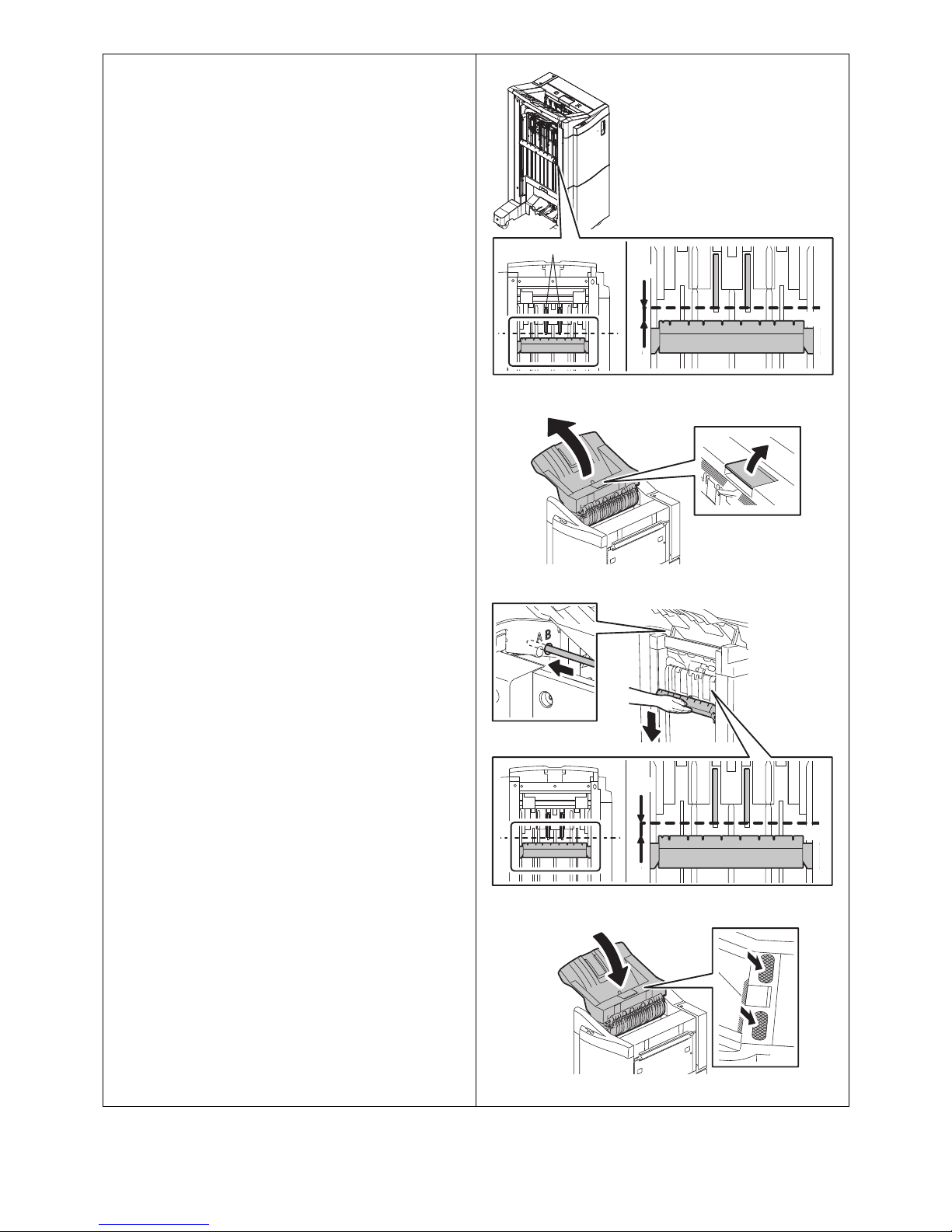
4. Fold the protective parts as shown in the
figure.
• 2 places
5. Insert [R] as shown in the figure.
6. Raise the finisher as shown in the figure.
R
Page 4

© 2013 Oki Data Corporation. All rights reserved MJ-1108 with KN-2550
45686246EE
4 / 25
7. Remove the protective part and dispose of it.
8. Take off the finisher.
Remove the protective part and dispose of it.
9. Remove the protective parts as shown in the
figure and dispose of them.
10. Open the cover.
Page 5
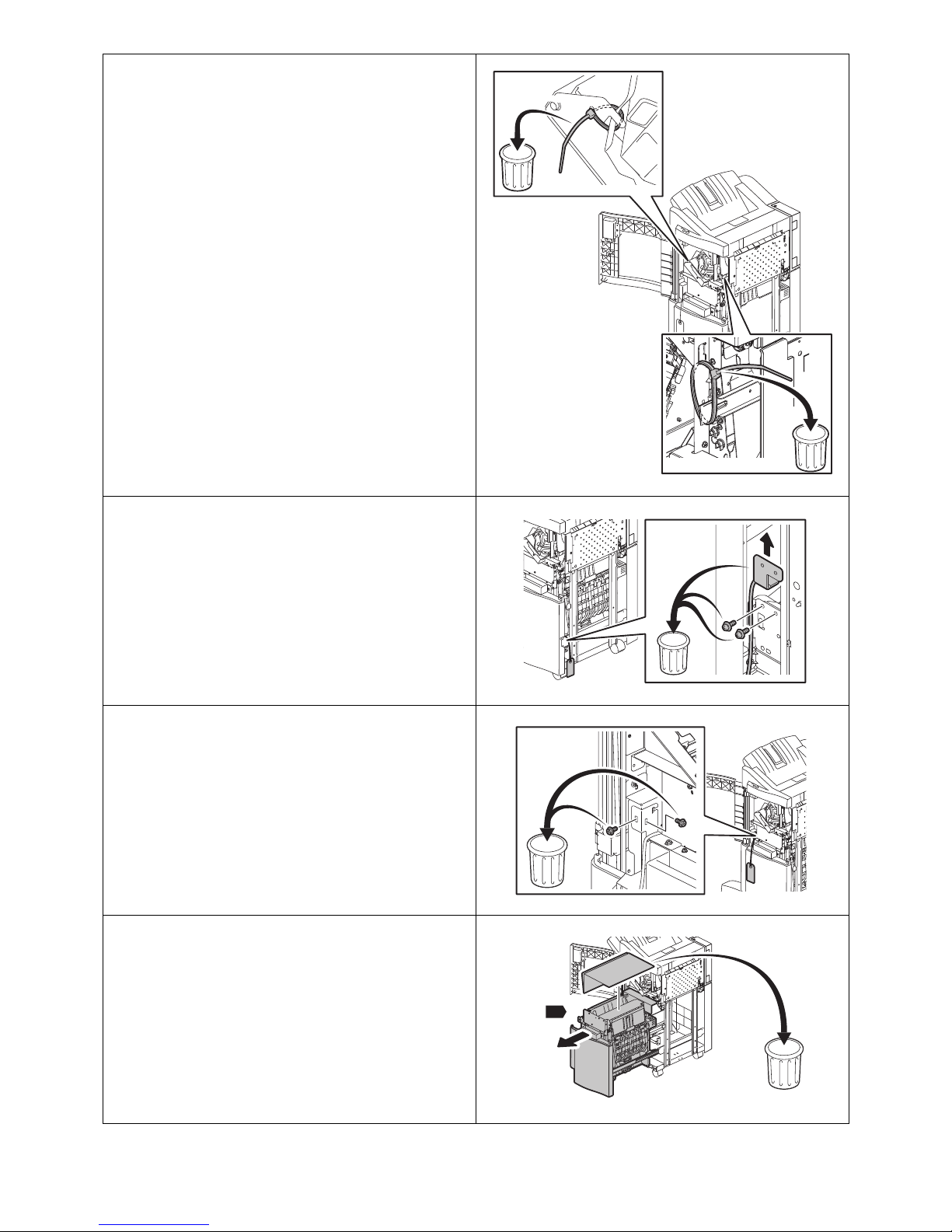
© 2013 Oki Data Corporation. All rights reserved MJ-1108 with KN-2550
45686246EE
5 / 25
11. Cut out the gray portions shown in the figure
and dispose of them.
• 2 places
12. Remove the screws and dispose of the
protective part and screws.
• Screws: 2
13. Remove the screws and dispose of them.
• Screws: 2
14. Pull out [U].
Remove the protective part and dispose of it.
U
Page 6

© 2013 Oki Data Corporation. All rights reserved MJ-1108 with KN-2550
45686246EE
6 / 25
15. Remove the screw and dispose of the
protective part.
• Screw: 1
16. Cut out the gray portion shown in the figure
and dispose of it.
• 1 place
17. Hold the tabs as shown in the figure and open
[V].
• 2 places
V
Page 7

© 2013 Oki Data Corporation. All rights reserved MJ-1108 with KN-2550
45686246EE
7 / 25
18. Cut out the gray portion shown in the figure
and dispose of it.
• 1 place
19. Hold the tabs as shown in the figure and
close [V].
• 2 places
20. Open the cover, remove the protective parts
and dispose of them.
• 2 places
21. Close the cover.
V
Page 8

© 2013 Oki Data Corporation. All rights reserved MJ-1108 with KN-2550
45686246EE
8 / 25
22. Remove [ff].
• ff: 2
23. Temporarily tighten [ff].
• ff: 2
24. Close [U].
25. Close the cover.
26. Remove the screw and take off the cover.
• Screw: 1
ff
ff
ff
ff
U
Page 9

© 2013 Oki Data Corporation. All rights reserved MJ-1108 with KN-2550
45686246EE
9 / 25
27. Remove the screws and dispose of them.
• Screws: 2
28. Attach the cover with the screw.
• Screw: 1
29. Remove the packing materials of KN-2550.
30. Take out the accessories of KN-2550.
31. Cut out the gray portion shown in the figure
and dispose of it.
32. Cut out the gray portion shown in the figure
and dispose of it.
Page 10

© 2013 Oki Data Corporation. All rights reserved MJ-1108 with KN-2550
45686246EE
10 / 25
33. Open the cover.
34. Remove the screws and take off the cover.
• Screws: 4
35. Remove the screw and take off the cover.
• Screw: 1
B
A
Page 11

© 2013 Oki Data Corporation. All rights reserved MJ-1108 with KN-2550
45686246EE
11 / 25
36. Cut out the gray portion shown in the figure
and dispose of it.
37. Wire the cable of [N] as shown in the figure.
38. Attach [A] to [N] with [r] as shown in the
figure.
•r: 2
N
r
A
N
r
Page 12
© 2013 Oki Data Corporation. All rights reserved MJ-1108 with KN-2550
45686246EE
12 / 25
39. Insert [N] as shown in the figure.
40. Attach [N] with [a].
•a: 2
41. Attach [N] with [t].
•t: 1
42. Open the cover.
N
N
a
a
t
N
Page 13
© 2013 Oki Data Corporation. All rights reserved MJ-1108 with KN-2550
45686246EE
13 / 25
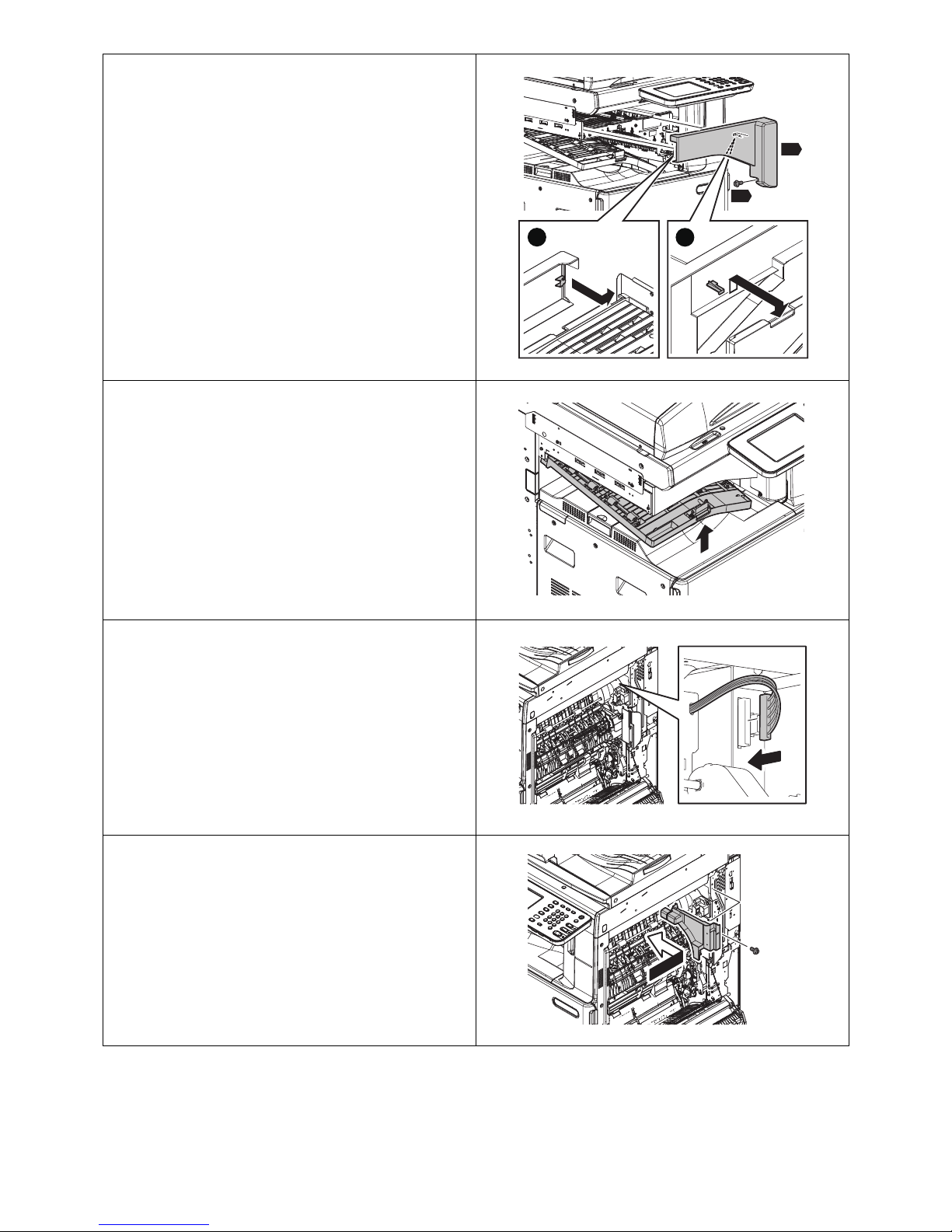
43. Attach [P] with [ee].
Attach (A) and then (B) in order, as shown in
the figure.
• ee: 1
44. Close the cover.
45. Connect the cable connector as shown in the
figure.
46. Attach the cover with the screw.
• Screw: 1
P
ee
B
A
Page 14
© 2013 Oki Data Corporation. All rights reserved MJ-1108 with KN-2550
45686246EE
14 / 25
47. Attach the cover with the screws.
• Screws: 4
48. Close the cover.
A
B
Page 15

© 2013 Oki Data Corporation. All rights reserved MJ-1108 with KN-2550
45686246EE
15 / 25
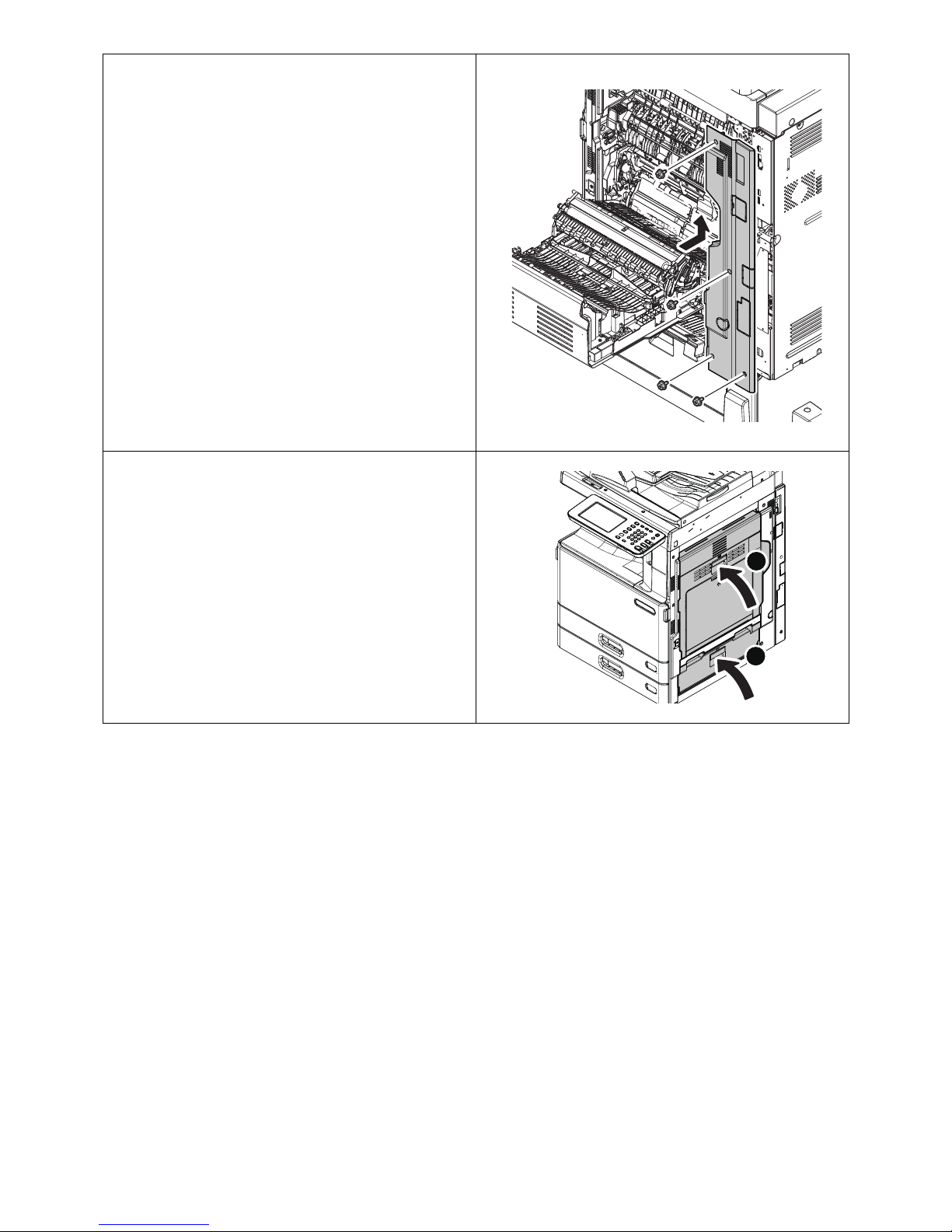
49. Attach [B] with [b] as shown in the figure.
•b: 2
50. Attach [I] with [e] as shown in the figure.
•e: 2
B
b
b
e
I
e
Page 16
© 2013 Oki Data Corporation. All rights reserved MJ-1108 with KN-2550
45686246EE
16 / 25
51. Check the gap between [AA] and [BB].
* If there is no gap, lower [BB] by referring to
the figure.
* If there is a gap, proceed to the next step.
AA
BB
AA
BB
AA
Page 17

© 2013 Oki Data Corporation. All rights reserved MJ-1108 with KN-2550
45686246EE
17 / 25
52. Attach [D] with [f].
•f: 2
* Be careful not to catch the harness.
53. Remove the protective part and dispose of it.
D
f
Page 18

© 2013 Oki Data Corporation. All rights reserved MJ-1108 with KN-2550
45686246EE
18 / 25
54. Hook [W] to the protrusion of [S].
55. Attach [E] with [g] as shown in the figure.
•g: 2
56. Insert [F].
57. Check the mobility of [G].
* Check that the leveling arm moves back and
forth smoothly. If not, push in its shaft and
check again.
W
S
g
g
E
F
G
Page 19

© 2013 Oki Data Corporation. All rights reserved MJ-1108 with KN-2550
45686246EE
19 / 25
58. Attach [G] with [h].
•h: 2
59. Pull out the lever as shown in the figure.
60. Insert by aligning the pins of the MFP with the
holes on [T].
h
h
G
T
Page 20

© 2013 Oki Data Corporation. All rights reserved MJ-1108 with KN-2550
45686246EE
20 / 25
61. Check the positions of [T] and MFP.
* If the gap between [T] and MFP is 10 mm or
more, adjust it.
P.21 “Gap Adjustment”
62. Attach the lever with [m] as shown in the
figure.
•m: 1
63. Close the cover.
64. Cut out the gray portion shown in the figure
and dispose of it.
T
0~10mm
m
Page 21

© 2013 Oki Data Corporation. All rights reserved MJ-1108 with KN-2550
45686246EE
21 / 25
Gap Adjustment
65. Connect the cable connector.
66. Attach the cover [H].
67. Secure the cable with [aa] as shown in the
figure.
* Cut out the unnecessary part of [aa] and
dispose of it.
68. The setup is now completed.
1. Pull out [T].
H
aa
T
Page 22

© 2013 Oki Data Corporation. All rights reserved MJ-1108 with KN-2550
45686246EE
22 / 25
2. Remove the screws and take off the covers.
• Screws: 2
• Covers: 2
3. Adjust the height of [X].
1) Loosen the two screws [1].
2) Adjust the height by turning the adjustment
screw [2].
3) Tighten the two screws [1].
4. Adjust the height of [Z].
1) Loosen the two screws [1].
2) Adjust the height by turning the adjustment
screw [2].
3) Tighten the two screws [1].
X
[1][
1
]
[2]
Z
[1][
1
]
[2]
Page 23
© 2013 Oki Data Corporation. All rights reserved MJ-1108 with KN-2550
45686246EE
23 / 25
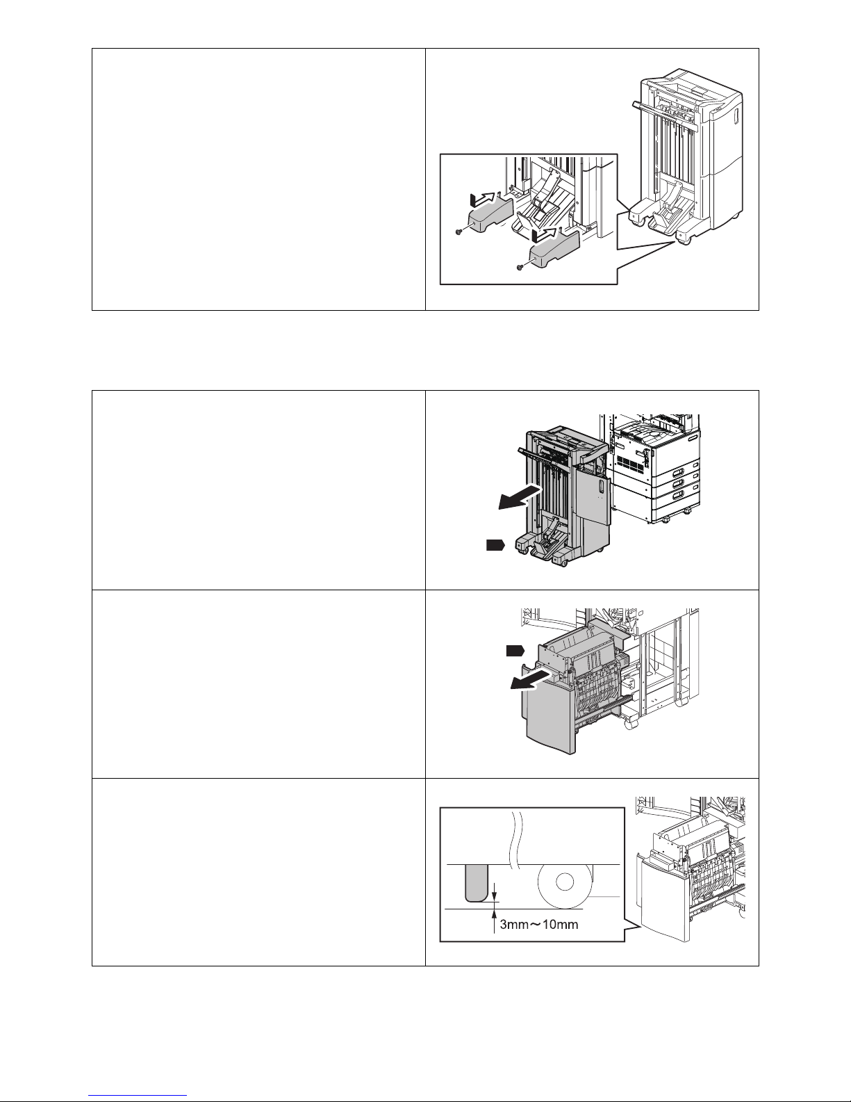
Fall-prevention Stopper Height Adjustment
[ 1 ] Check Method
5. Attach the covers with the screws.
• Screws: 2
• Covers: 2
1. Pull out [T].
2. Pull out [U].
3. Check that there is a gap of 3 to 10 mm
between the fall-prevention stopper and the
floor.
T
U
Page 24

© 2013 Oki Data Corporation. All rights reserved MJ-1108 with KN-2550
45686246EE
24 / 25
[ 2 ] Adjustment Method
4. If the fall-prevention stopper touches the
floor or there is a gap of more than 10 mm,
perform [2] Adjustment Method.
1. Remove the screws and take off the cover.
• Screws: 3
• Cover: 1
2. Loosen the height adjustment screws of the
fall-prevention stopper.
3. Adjust the height so that the gap between the
fall-prevention stopper and the floor is 3 to 10
mm.
4. Tighten the height adjustment screws of the
fall-prevention stopper.
Page 25

© 2013 Oki Data Corporation. All rights reserved MJ-1108 with KN-2550
45686246EE
25 / 25
5. Attach the cover with the screws.
• Screws: 3
• Cover: 1
Page 26

© 2013 Oki Data Corporation. All rights reserved MJ-1108 with KN-2550
45686246EE
1 / 25
MJ-1108 with KN-2550
UIM13004000 Ver00 F
GUIDE D'INSTALLATION
Avertissements et mises en garde
• Le déballage et l'installation ne doivent être effectués que par un technicien qualifié.
• Débranchez toujours le cordon d'alimentation de l'appareil avant d'installer et d'assembler le produit.
• Installez l'appareil près d'une prise de courant. Branchez bien le cordon d'alimentation, de façon à ce qu'il ne
puisse pas être débranché accidentellement, et à ne pas trébucher.
• Selon le modèle de l'appareil, les illustrations peuvent être différentes.
• Lorsque vous soulevez l'appareil, assurez-vous que cela soit effectué par deux personnes et que l'appareil
n'est jamais soulevé par la partie ombrée indiquée sur la figure.
• Lorsque vous déplacez l'appareil, poussez dans le sens de la flèche.
Page 27

© 2013 Oki Data Corporation. All rights reserved MJ-1108 with KN-2550
45686246EE
2 / 25
Accessoires
Installation
1. Enlevez les matériaux d’emballage du
MJ-1108.
2. Sortez les accessoires du MJ-1108.
3. Enlevez [R].
Jetez la pièce de protection.
A B J L Q
I
D E
F G H
for MJ-6104
M3x8
g
aa
M4x20
b
M4x20
e
M3x8
f
M3x8hM3x8
m
bb
a
TBID
M4x10
M3x8
for MJ-6104
MJ-1108
N P
r
ee
M4x8 M3x6
t
M3x6
KN-2550
R
Page 28
© 2013 Oki Data Corporation. All rights reserved MJ-1108 with KN-2550
45686246EE
3 / 25
4. Pliez les pièces de protection comme indiqué
sur la figure.
• 2 endroits
5. Insérez [R] comme indiqué sur l'illustration.
6. Soulevez le module de finition comme
indiqué sur la figure.
R
Page 29

© 2013 Oki Data Corporation. All rights reserved MJ-1108 with KN-2550
45686246EE
4 / 25
7. Retirez la pièce de protection et débarrassezvous en.
8. Retirez le module de finition.
Retirez la pièce de protection et débarrassezvous en.
9. Retirez les parties protectrices indiquées sur
l'illustration et jetez-les.
10. Ouvrez le couvercle.
Page 30

© 2013 Oki Data Corporation. All rights reserved MJ-1108 with KN-2550
45686246EE
5 / 25
11. Coupez les parties grises indiquées sur
l'illustration et jetez-les.
• 2 endroits
12. Retirez les vis et jetez la pièce de protection
et les vis.
• Vis : 2
13. Dévissez les vis et jetez-les.
• Vis : 2
14. Tirez [U].
Retirez la pièce de protection et débarrassezvous en.
U
Page 31

© 2013 Oki Data Corporation. All rights reserved MJ-1108 with KN-2550
45686246EE
6 / 25
15. Retirez les vis et jetez la pièce de protection.
•Vis: 1
16. Coupez la partie grise indiquée sur
l'illustration et jetez-la.
• 1 endroit
17. Saisissez les languettes comme indiqué sur
la figure et ouvrez [V].
• 2 endroits
V
Page 32

© 2013 Oki Data Corporation. All rights reserved MJ-1108 with KN-2550
45686246EE
7 / 25
18. Coupez la partie grise indiquée sur
l'illustration et jetez-la.
• 1 endroit
19. Saisissez les languettes comme indiqué sur
la figure et fermez [V].
• 2 endroits
20. Ouvrez le couvercle, retirez les éléments de
protection et débarrassez-vous en.
• 2 endroits
21. Fermez le couvercle.
V
Page 33

© 2013 Oki Data Corporation. All rights reserved MJ-1108 with KN-2550
45686246EE
8 / 25
22. Enlevez [ff].
• ff: 2
23. Serrez provisoirement [ff].
• ff: 2
24. Fermez [U].
25. Fermez le couvercle.
26. Dévissez la vis et retirez le couvercle.
•Vis: 1
ff
ff
ff
ff
U
Page 34

© 2013 Oki Data Corporation. All rights reserved MJ-1108 with KN-2550
45686246EE
9 / 25
27. Dévissez les vis et jetez-les.
• Vis : 2
28. Attachez le couvercle avec la vis.
•Vis: 1
29. Enlevez les matériaux d’emballage du
KN-2550.
30. Sortez les accessoires de KN-2550.
31. Coupez la partie grise indiquée sur
l'illustration et jetez-la.
32. Coupez la partie grise indiquée sur
l'illustration et jetez-la.
Page 35

© 2013 Oki Data Corporation. All rights reserved MJ-1108 with KN-2550
45686246EE
10 / 25
33. Ouvrez le couvercle.
34. Dévissez les vis et retirez le couvercle.
• Vis : 4
35. Dévissez la vis et retirez le couvercle.
•Vis: 1
B
A
Page 36

© 2013 Oki Data Corporation. All rights reserved MJ-1108 with KN-2550
45686246EE
11 / 25
36. Coupez la partie grise indiquée sur
l'illustration et jetez-la.
37. Branchez le câble de [N] comme indiqué sur
l'illustration.
38. Attachez [A] à [N] avec [r] comme indiqué sur
l'illustration.
•r : 2
N
r
A
N
r
Page 37

© 2013 Oki Data Corporation. All rights reserved MJ-1108 with KN-2550
45686246EE
12 / 25
39. Insérez [N] comme indiqué sur l'illustration.
40. Attachez [N] avec [a].
•a : 2
41. Attachez [N] avec [t].
• t : 1
42. Ouvrez le couvercle.
N
N
a
a
t
N
Page 38

© 2013 Oki Data Corporation. All rights reserved MJ-1108 with KN-2550
45686246EE
13 / 25
43. Attachez [P] avec [ee].
Attachez (A) puis (B) dans l'ordre, comme
indiqué sur la figure.
• ee : 1
44. Fermez le couvercle.
45. Branchez le connecteur de câble comme
indiqué sur l'illustration.
46. Attachez le couvercle avec la vis.
•Vis: 1
P
ee
B
A
Page 39

© 2013 Oki Data Corporation. All rights reserved MJ-1108 with KN-2550
45686246EE
14 / 25
47. Attachez le couvercle avec les vis.
• Vis : 4
48. Fermez le couvercle.
A
B
Page 40

© 2013 Oki Data Corporation. All rights reserved MJ-1108 with KN-2550
45686246EE
15 / 25
49. Attachez [B] à [b] comme indiqué sur
l'illustration.
•b : 2
50. Attachez [I] à [e] comme indiqué sur
l'illustration.
•e : 2
B
b
b
e
I
e
Page 41

© 2013 Oki Data Corporation. All rights reserved MJ-1108 with KN-2550
45686246EE
16 / 25
51. Vérifiez l'écart entre [AA] et [BB].
* S'il n'y a pas d'écart, abaissez [BB] en vous
référant à la figure.
* S'il y a un écart, passez à l'étape suivante.
AA
BB
AA
BB
AA
Page 42

© 2013 Oki Data Corporation. All rights reserved MJ-1108 with KN-2550
45686246EE
17 / 25
52. Attachez [D] avec [f].
• f : 2
* Faites attention à ne pas attraper le harnais.
53. Retirez la pièce de protection et débarrassezvous en.
D
f
Page 43

© 2013 Oki Data Corporation. All rights reserved MJ-1108 with KN-2550
45686246EE
18 / 25
54. Accrochez [W] à la saillie de [S].
55. Attachez [E] à [g] comme indiqué sur
l'illustration.
•g : 2
56. Insérez [F].
57. Vérifiez la mobilité de [G].
* Assurez-vous que le bras de nivellement se
déplace d'avant en arrière en douceur. Sinon,
appuyez sur son axe et vérifiez à nouveau.
W
S
g
g
E
F
G
Page 44

© 2013 Oki Data Corporation. All rights reserved MJ-1108 with KN-2550
45686246EE
19 / 25
58. Attachez [G] avec [h].
•h : 2
59. Tirez sur le levier comme indiqué sur la
figure.
60. Insérez en alignant les broches du MFP avec
les trous sur [T].
h
h
G
T
Page 45

© 2013 Oki Data Corporation. All rights reserved MJ-1108 with KN-2550
45686246EE
20 / 25
61. Vérifiez les positions de [T] et MFP.
* Si l'écart entre [T] et MFP est de 10 mm ou
plus, ajustez-le.
P.21 “Réglage de l'écartement”
62. Fixez le levier avec [m] comme indiqué sur la
figure.
•m : 1
63. Fermez le couvercle.
64. Coupez la partie grise indiquée sur
l'illustration et jetez-la.
T
0~10mm
m
Page 46

© 2013 Oki Data Corporation. All rights reserved MJ-1108 with KN-2550
45686246EE
21 / 25
Réglage de l'écartement
65. Branchez le connecteur de câble.
66. Attachez le couvercle [H].
67. Fixez le câble avec [aa] comme indiqué sur
l'illustration.
* Coupez la partie inutile de [aa] et jetez-la.
68. L'installation est terminée.
1. Tirez [T].
H
aa
T
Page 47

© 2013 Oki Data Corporation. All rights reserved MJ-1108 with KN-2550
45686246EE
22 / 25
2. Dévissez les vis et retirez les couvercles.
• Vis : 2
• Couvercles : 2
3. Ajustez la hauteur de [X].
1) Desserrez les deux vis [1].
2) Ajustez la hauteur en tournant la vis de
réglage [2].
3) Serrez les deux vis [1].
4. Ajustez la hauteur de [Z].
1) Desserrez les deux vis [1].
2) Ajustez la hauteur en tournant la vis de
réglage [2].
3) Serrez les deux vis [1].
X
[1][
1
]
[2]
Z
[1][
1
]
[2]
Page 48

© 2013 Oki Data Corporation. All rights reserved MJ-1108 with KN-2550
45686246EE
23 / 25
Réglage de la hauteur de la butée de sécurité anti chute
[ 1 ] Méthode de vérification
5. Attachez les couvercles avec les vis.
• Vis : 2
• Couvercles : 2
1. Tirez [T].
2. Tirez [U].
3. Vérifiez qu'il y a un espace de 3 à 10 mm entre
la butée anti chute et le sol.
T
U
Page 49

© 2013 Oki Data Corporation. All rights reserved MJ-1108 with KN-2550
45686246EE
24 / 25
[ 2 ] Méthode de réglage
4. Si la butée anti chute touche le sol ou s'il y a
un écart de plus de 10 mm, exécutez la
commande [2] Méthode de réglage.
1. Dévissez les vis et retirez le couvercle.
• Vis : 3
• Couvercle : 1
2. Desserrez la hauteur de réglage des vis de la
butée anti-chute.
3. Ajustez la hauteur de telle sorte que l'écart
entre la butée anti-chute et le sol soit de 3 à
10 mm.
4. Serrez la hauteur de réglage des vis de la
butée anti-chute.
Page 50

© 2013 Oki Data Corporation. All rights reserved MJ-1108 with KN-2550
45686246EE
25 / 25
5. Attachez le couvercle avec les vis.
• Vis : 3
• Couvercle : 1
Page 51

© 2013 Oki Data Corporation. All rights reserved MJ-1108 with KN-2550
45686246EE
1 / 25
MJ-1108 with KN-2550
UIM13004000 Ver00 F
Einrichtungsanleitung
Warnungen und Vorsichtshinweise
• Das Gerät muss von einem qualifizierten Servicetechniker ausgepackt und eingerichtet werden.
• Achten Sie darauf, dass der Netzstecker nicht vor Abschluss der Aufstellung und Einrichtung eingesteckt
wird.
• Stellen Sie das Gerät in der Nähe einer Steckdose auf. Sorgen Sie dafür, dass das Netzkabel ordentlich
verlegt wird: So, dass niemand darüber stolpern kann, aber der Netzstecker stets erreichbar bleibt.
• Die Illustrationen können je nach Modell etwas abweichen.
• Heben Sie das Gerät unbedingt mit zwei Personen an; achten Sie darauf, dass das Gerät niemals an der
schattierten Stelle (siehe Abbildung) gehalten wird.
• Bewegen Sie das Gerät zum Verschieben in Pfeilrichtung.
Page 52

© 2013 Oki Data Corporation. All rights reserved MJ-1108 with KN-2550
45686246EE
2 / 25
Zubehör
Einrichtung
1. Entfernen Sie das MJ-1108Verpackungsmaterial.
2. Nehmen Sie das MJ-1108-Zubehör heraus.
3. Entfernen Sie [R].
Entsorgen Sie den Schutz.
A B J L Q
I
D E
F G H
for MJ-6104
M3x8
g
aa
M4x20
b
M4x20
e
M3x8
f
M3x8hM3x8
m
bb
a
TBID
M4x10
M3x8
for MJ-6104
MJ-1108
N P
r
ee
M4x8 M3x6
t
M3x6
KN-2550
R
Page 53

© 2013 Oki Data Corporation. All rights reserved MJ-1108 with KN-2550
45686246EE
3 / 25
4. Legen Sie die schützenden Teile wie in der
Abbildung gezeigt zusammen.
• 2 Stellen
5. Setzen Sie [R] wie in der Abbildung gezeigt
ein.
6. Heben Sie den Finisher wie in der Abbildung
gezeigt an.
R
Page 54

© 2013 Oki Data Corporation. All rights reserved MJ-1108 with KN-2550
45686246EE
4 / 25
7. Entfernen und entsorgen Sie den Schutz.
8. Nehmen Sie den Finisher ab.
Entfernen und entsorgen Sie den Schutz.
9. Entfernen und entsorgen Sie die in der
Abbildung gezeigten schützenden Teile.
10. Öffnen Sie die Abdeckung.
Page 55

© 2013 Oki Data Corporation. All rights reserved MJ-1108 with KN-2550
45686246EE
5 / 25
11. Schneiden Sie die grauen in der Abbildung
gezeigten Teile heraus; anschließend
entsorgen.
• 2 Stellen
12. Entfernen Sie die Schrauben, entsorgen Sie
diese gemeinsam mit den schützenden
Tei len.
• Schrauben: 2
13. Entfernen und entsorgen Sie die Schrauben.
• Schrauben: 2
14. Ziehen Sie [U] heraus.
Entfernen und entsorgen Sie den Schutz.
U
Page 56

© 2013 Oki Data Corporation. All rights reserved MJ-1108 with KN-2550
45686246EE
6 / 25
15. Entfernen Sie die Schraube, entsorgen Sie
den Schutz.
• Schraube: 1
16. Schneiden Sie den grauen in der Abbildung
gezeigten Teil heraus; anschließend
entsorgen.
• 1 Stelle
17. Halten Sie die Laschen wie in der Abbildung
gezeigt, öffnen Sie [V].
• 2 Stellen
V
Page 57

© 2013 Oki Data Corporation. All rights reserved MJ-1108 with KN-2550
45686246EE
7 / 25
18. Schneiden Sie den grauen in der Abbildung
gezeigten Teil heraus; anschließend
entsorgen.
• 1 Stelle
19. Halten Sie die Laschen wie in der Abbildung
gezeigt, schließen Sie [V].
• 2 Stellen
20. Öffnen Sie die Abdeckung, entfernen und
entsorgen Sie die schützenden Teile.
• 2 Stellen
21. Schließen Sie die Abdeckung.
V
Page 58

© 2013 Oki Data Corporation. All rights reserved MJ-1108 with KN-2550
45686246EE
8 / 25
22. Entfernen Sie [ff].
• ff: 2
23. Ziehen Sie [ff] vorübergehend an.
• ff: 2
24. Schließen Sie [U].
25. Schließen Sie die Abdeckung.
26. Drehen Sie die Schraube heraus, nehmen Sie
die Abdeckung ab.
• Schraube: 1
ff
ff
ff
ff
U
Page 59

© 2013 Oki Data Corporation. All rights reserved MJ-1108 with KN-2550
45686246EE
9 / 25
27. Entfernen und entsorgen Sie die Schrauben.
• Schrauben: 2
28. Fixieren Sie die Abdeckung mit der Schraube.
• Schraube: 1
29. Entfernen Sie das KN-2550Verpackungsmaterial.
30. Nehmen Sie das KN-2550-Zubehör heraus.
31. Schneiden Sie den grauen in der Abbildung
gezeigten Teil heraus; anschließend
entsorgen.
32. Schneiden Sie den grauen in der Abbildung
gezeigten Teil heraus; anschließend
entsorgen.
Page 60

© 2013 Oki Data Corporation. All rights reserved MJ-1108 with KN-2550
45686246EE
10 / 25
33. Öffnen Sie die Abdeckung.
34. Drehen Sie die Schrauben heraus, nehmen
Sie die Abdeckung ab.
• Schrauben: 4
35. Drehen Sie die Schraube heraus, nehmen Sie
die Abdeckung ab.
• Schraube: 1
B
A
Page 61

© 2013 Oki Data Corporation. All rights reserved MJ-1108 with KN-2550
45686246EE
11 / 25
36. Schneiden Sie den grauen in der Abbildung
gezeigten Teil heraus; anschließend
entsorgen.
37. Verlegen Sie das Kabel von [N] wie in der
Abbildung gezeigt.
38. Bringen Sie [A] wie in der Abbildung gezeigt
mit [r] an [N] an.
•r: 2
N
r
A
N
r
Page 62

© 2013 Oki Data Corporation. All rights reserved MJ-1108 with KN-2550
45686246EE
12 / 25
39. Setzen Sie [N] wie in der Abbildung gezeigt
ein.
40. Bringen Sie [N] mit [a] an.
•a: 2
41. Befestigen Sie [N] mit [t].
•t: 1
42. Öffnen Sie die Abdeckung.
N
N
a
a
t
N
Page 63

© 2013 Oki Data Corporation. All rights reserved MJ-1108 with KN-2550
45686246EE
13 / 25
43. Befestigen Sie [P] mit [ee].
Bringen Sie erst (A), dann (B) wie in der
Abbildung gezeigt an.
• ee: 1
44. Schließen Sie die Abdeckung.
45. Schließen Sie den Kabelverbinder wie in der
Abbildung gezeigt an.
46. Fixieren Sie die Abdeckung mit der Schraube.
• Schraube: 1
P
ee
B
A
Page 64

© 2013 Oki Data Corporation. All rights reserved MJ-1108 with KN-2550
45686246EE
14 / 25
47. Fixieren Sie die Abdeckung mit den
Schrauben.
• Schrauben: 4
48. Schließen Sie die Abdeckung.
A
B
Page 65

© 2013 Oki Data Corporation. All rights reserved MJ-1108 with KN-2550
45686246EE
15 / 25
49. Bringen Sie [B] wie in der Abbildung gezeigt
mit [b] an.
•b: 2
50. Bringen Sie [I] wie in der Abbildung gezeigt
mit [e] an.
•e: 2
B
b
b
e
I
e
Page 66

© 2013 Oki Data Corporation. All rights reserved MJ-1108 with KN-2550
45686246EE
16 / 25
51. Prüfen Sie den Spalt zwischen [AA] und [BB].
* Wenn kein Spalt vorhanden ist, senken Sie
[BB] ab; schauen Sie sich dazu die Abbildung
an.
* Wenn ein Spalt existiert, fahren Sie mit dem
nächsten Schritt fort.
AA
BB
AA
BB
AA
Page 67

© 2013 Oki Data Corporation. All rights reserved MJ-1108 with KN-2550
45686246EE
17 / 25
52. Bringen Sie [D] mit [f] an.
•f: 2
* Achten Sie darauf, dass sich der Kabelstrang
nicht verfängt.
53. Entfernen und entsorgen Sie den Schutz.
D
f
Page 68

© 2013 Oki Data Corporation. All rights reserved MJ-1108 with KN-2550
45686246EE
18 / 25
54. Haken Sie [W] am Vorsprung von [S] ein.
55. Bringen Sie [E] wie in der Abbildung gezeigt
mit [g] an.
•g: 2
56. Setzen Sie [F] ein.
57. Prüfen Sie die Beweglichkeit von [G].
* Vergewissern Sie sich, dass sich der
Ausgleichsarm frei vorwärts und rückwärts
bewegen lässt. Falls nicht, drücken Sie
dessen Achse ein und prüfen anschließend
noch einmal.
W
S
g
g
E
F
G
Page 69

© 2013 Oki Data Corporation. All rights reserved MJ-1108 with KN-2550
45686246EE
19 / 25
58. Bringen Sie [G] mit [h] an.
•h: 2
59. Ziehen Sie den Hebel wie in der Abbildung
gezeigt heraus.
60. Einsetzen, indem Sie die Stifte am MFP mit
den Öffnungen in [T] in Flucht bringen.
h
h
G
T
Page 70

© 2013 Oki Data Corporation. All rights reserved MJ-1108 with KN-2550
45686246EE
20 / 25
61. Prüfen Sie die Positionen von [T] und MFP.
* Falls der Spalt zwischen [T] und MFP 10 mm
oder mehr beträgt, entsprechend justieren.
P.21 “Spalteinstellung”
62. Bringen Sie den Hebel wie in der Abbildung
gezeigt mit [m] an.
•m: 1
63. Schließen Sie die Abdeckung.
64. Schneiden Sie den grauen in der Abbildung
gezeigten Teil heraus; anschließend
entsorgen.
T
0~10mm
m
Page 71

© 2013 Oki Data Corporation. All rights reserved MJ-1108 with KN-2550
45686246EE
21 / 25
Spalteinstellung
65. Schließen Sie den Kabelverbinder an.
66. Bringen Sie die Abdeckung [H] an.
67. Fixieren Sie das Kabel wie in der Abbildung
gezeigt mit [aa].
* Schneiden Sie den nicht benötigten Teil von
[aa] aus, entsorgen Sie diesen.
68. Die Einrichtung ist nun abgeschlossen.
1. Ziehen Sie [T] heraus.
H
aa
T
Page 72

© 2013 Oki Data Corporation. All rights reserved MJ-1108 with KN-2550
45686246EE
22 / 25
2. Drehen Sie die Schrauben heraus, nehmen
Sie die Abdeckungen ab.
• Schrauben: 2
• Abdeckungen: 2
3. Passen Sie die Höhe von [X] an.
1) Lösen Sie die beiden Schrauben [1].
2) Stellen Sie die Höhe durch Drehen der
Einstellschraube [2] ein.
3) Ziehen Sie die beiden Schrauben [1] an.
4. Passen Sie die Höhe von [Z] an.
1) Lösen Sie die beiden Schrauben [1].
2) Stellen Sie die Höhe durch Drehen der
Einstellschraube [2] ein.
3) Ziehen Sie die beiden Schrauben [1] an.
X
[1][
1
]
[2]
Z
[1][
1
]
[2]
Page 73

© 2013 Oki Data Corporation. All rights reserved MJ-1108 with KN-2550
45686246EE
23 / 25
Fallpräventionsstopper-Höhenverstellung
[ 1 ] Prüfverfahren
5. Fixieren Sie die Abdeckungen mit den
Schrauben.
• Schrauben: 2
• Abdeckungen: 2
1. Ziehen Sie [T] heraus.
2. Ziehen Sie [U] heraus.
3. Vergewissern Sie sich, dass zwischen
Fallpräventionsstopper und Boden ein Spalt
von 3 – 10 mm verbleibt.
T
U
Page 74

© 2013 Oki Data Corporation. All rights reserved MJ-1108 with KN-2550
45686246EE
24 / 25
[ 2 ] Justierungsverfahren
4. Falls der Fallpräventionsstopper den Boden
berührt oder ein Spalt von mehr als 10 mm
vorhanden ist, führen Sie das
Justierungsverfahren [2] durch.
1. Drehen Sie die Schrauben heraus, nehmen
Sie die Abdeckung ab.
• Schrauben: 3
• Abdeckung: 1
2. Lösen Sie die Höhenverstellungsschrauben
am Fallpräventionsstopper.
3. Stellen Sie die Höhe so ein, dass der Spalt
zwischen Fallpräventionsstopper und Boden
3 – 10 mm beträgt.
4. Ziehen Sie die Höhenverstellungsschrauben
am Fallpräventionsstopper an.
Page 75

© 2013 Oki Data Corporation. All rights reserved MJ-1108 with KN-2550
45686246EE
25 / 25
5. Fixieren Sie die Abdeckung mit den
Schrauben.
• Schrauben: 3
• Abdeckung: 1
Page 76

© 2013 Oki Data Corporation. All rights reserved MJ-1108 with KN-2550
45686246EE
1 / 25
MJ-1108 with KN-2550
UIM13004000 Ver00 F
GUÍA DE INSTALACIÓN
Advertencias y precauciones
• Solicite a un técnico de mantenimiento profesional que lleve a cabo el procedimiento de desembalaje e
instalación.
• Asegúrese de desenchufar el cable de alimentación del equipo antes de instalar el producto.
• Instale el equipo junto a una toma de corriente. Asegúrese de conectar el cable de alimentación de forma
segura para poder desconectarlo fácilmente y no tropezar con él.
• En función del modelo del equipo, estas ilustraciones pueden no coincidir exactamente con el equipo.
• Cuando levante el equipo, asegúrese de hacerlo con la ayuda de otra persona y de no sujetar nunca dicho
equipo por la parte sombreada indicada en la figura.
• Cuando traslade el equipo, empuje en la dirección de la flecha.
Page 77

© 2013 Oki Data Corporation. All rights reserved MJ-1108 with KN-2550
45686246EE
2 / 25
Accesorios
Instalación
1. Quite los materiales de embalaje de MJ-1108.
2. Saque los accesorios de MJ-1108.
3. Quite [R].
Deseche el protector.
A B J L Q
I
D E
F G H
for MJ-6104
M3x8
g
aa
M4x20
b
M4x20
e
M3x8
f
M3x8hM3x8
m
bb
a
TBID
M4x10
M3x8
for MJ-6104
MJ-1108
N P
r
ee
M4x8 M3x6
t
M3x6
KN-2550
R
Page 78

© 2013 Oki Data Corporation. All rights reserved MJ-1108 with KN-2550
45686246EE
3 / 25
4. Doble los protectores como se indica en la
figura.
• 2 lugares
5. Inserte [R] como se indica en la figura.
6. Levante la unidad de acabado como se indica
en la figura.
R
Page 79

© 2013 Oki Data Corporation. All rights reserved MJ-1108 with KN-2550
45686246EE
4 / 25
7. Quite el protector y deséchelo.
8. Quite la unidad de acabado.
Quite el protector y deséchelo.
9. Quite los protectores como se indica en la
figura y deséchelos.
10. Abra la cubierta.
Page 80

© 2013 Oki Data Corporation. All rights reserved MJ-1108 with KN-2550
45686246EE
5 / 25
11. Recorte las partes grises indicadas en la
figura y deséchelas.
• 2 lugares
12. Quite los tornillos y deséchelos junto al
protector.
• Tornillos: 2
13. Quite los tornillos y deséchelos.
• Tornillos: 2
14. Extraiga [U].
Quite el protector y deséchelo.
U
Page 81

© 2013 Oki Data Corporation. All rights reserved MJ-1108 with KN-2550
45686246EE
6 / 25
15. Quite el tornillo y deseche el protector.
• Tornillo: 1
16. Recorte la parte gris indicada en la figura y
deséchela.
• 1 lugar
17. Presione las lengüetas como se indica en la
figura y abra [V].
• 2 lugares
V
Page 82

© 2013 Oki Data Corporation. All rights reserved MJ-1108 with KN-2550
45686246EE
7 / 25
18. Recorte la parte gris indicada en la figura y
deséchela.
• 1 lugar
19. Presione las lengüetas como se indica en la
figura y cierre [V].
• 2 lugares
20. Abra la cubierta, quite los protectores y
deséchelos.
• 2 lugares
21. Cierre la cubierta.
V
Page 83

© 2013 Oki Data Corporation. All rights reserved MJ-1108 with KN-2550
45686246EE
8 / 25
22. Quite [ff].
• ff: 2
23. Apriete temporalmente [ff].
• ff: 2
24. Cierre [U].
25. Cierre la cubierta.
26. Quite el tornillo y retire la cubierta.
• Tornillo: 1
ff
ff
ff
ff
U
Page 84

© 2013 Oki Data Corporation. All rights reserved MJ-1108 with KN-2550
45686246EE
9 / 25
27. Quite los tornillos y deséchelos.
• Tornillos: 2
28. Fije la cubierta con el tornillo.
• Tornillo: 1
29. Quite los materiales de embalaje de KN-2550.
30. Saque los accesorios de KN-2550.
31. Recorte la parte gris indicada en la figura y
deséchela.
32. Recorte la parte gris indicada en la figura y
deséchela.
Page 85

© 2013 Oki Data Corporation. All rights reserved MJ-1108 with KN-2550
45686246EE
10 / 25
33. Abra la cubierta.
34. Quite los tornillos y retire la cubierta.
• Tornillos: 4
35. Quite el tornillo y retire la cubierta.
• Tornillo: 1
B
A
Page 86

© 2013 Oki Data Corporation. All rights reserved MJ-1108 with KN-2550
45686246EE
11 / 25
36. Recorte la parte gris indicada en la figura y
deséchela.
37. Conecte el cable de [N] como se indica en la
figura.
38. Fije [A] a [N] con [r] como se indica en la
figura.
•r: 2
N
r
A
N
r
Page 87

© 2013 Oki Data Corporation. All rights reserved MJ-1108 with KN-2550
45686246EE
12 / 25
39. Inserte [N] como se indica en la figura.
40. Fije [N] con [a].
•a: 2
41. Fije [N] con [t].
•t: 1
42. Abra la cubierta.
N
N
a
a
t
N
Page 88

© 2013 Oki Data Corporation. All rights reserved MJ-1108 with KN-2550
45686246EE
13 / 25
43. Fije [P] con [ee].
Fije (A) y, a continuación, (B), en ese orden,
tal y como se indica en la figura.
• ee: 1
44. Cierre la cubierta.
45. Enchufe el conector de cables como se
indica en la figura.
46. Fije la cubierta con el tornillo.
• Tornillo: 1
P
ee
B
A
Page 89

© 2013 Oki Data Corporation. All rights reserved MJ-1108 with KN-2550
45686246EE
14 / 25
47. Fije la cubierta con los tornillos.
• Tornillos: 4
48. Cierre la cubierta.
A
B
Page 90

© 2013 Oki Data Corporation. All rights reserved MJ-1108 with KN-2550
45686246EE
15 / 25
49. Fije [B] con [b] como se indica en la figura.
•b: 2
50. Fije [I] con [e] como se indica en la figura.
•e: 2
B
b
b
e
I
e
Page 91

© 2013 Oki Data Corporation. All rights reserved MJ-1108 with KN-2550
45686246EE
16 / 25
51. Compruebe la distancia entre [AA] y [BB].
* Si la distancia es inexistente, baje [BB]
tomando como referencia la figura.
* Si la distancia existe, continúe con el
siguiente paso.
AA
BB
AA
BB
AA
Page 92

© 2013 Oki Data Corporation. All rights reserved MJ-1108 with KN-2550
45686246EE
17 / 25
52. Fije [D] con [f].
•f: 2
* Preste atención para no pillar el arnés.
53. Quite el protector y deséchelo.
D
f
Page 93

© 2013 Oki Data Corporation. All rights reserved MJ-1108 with KN-2550
45686246EE
18 / 25
54. Encaje [W] en el saliente de [S].
55. Fije [E] con [g] como se indica en la figura.
•g: 2
56. Inserte [F].
57. Compruebe la movilidad de [G].
* Compruebe que el brazo nivelador se mueve
libremente hacia atrás y adelante. Si no es
así, empuje su eje y vuelva a comprobarlo.
W
S
g
g
E
F
G
Page 94

© 2013 Oki Data Corporation. All rights reserved MJ-1108 with KN-2550
45686246EE
19 / 25
58. Fije [G] con [h].
•h: 2
59. Tire de la palanca como se indica en la figura.
60. Realice la inserción alineando los contactos
de la MFP con los orificios de [T].
h
h
G
T
Page 95

© 2013 Oki Data Corporation. All rights reserved MJ-1108 with KN-2550
45686246EE
20 / 25
61. Compruebe las posiciones de [T] y de la MFP.
* Si la distancia entre [T] y la MFP es de 10 mm
o superior, ajústela.
P.21 “Ajuste de la distancia”
62. Fije la posición de la palanca con [m] como
se indica en la figura.
•m: 1
63. Cierre la cubierta.
64. Recorte la parte gris indicada en la figura y
deséchela.
T
0~10mm
m
Page 96

© 2013 Oki Data Corporation. All rights reserved MJ-1108 with KN-2550
45686246EE
21 / 25
Ajuste de la distancia
65. Enchufe el conector de cables.
66. Fije la cubierta [H].
67. Asegure el cable con [aa] como se indica en
la figura.
* Recorte el exceso de [aa] y deséchelo.
68. La instalación ha finalizado.
1. Tire de [T].
H
aa
T
Page 97

© 2013 Oki Data Corporation. All rights reserved MJ-1108 with KN-2550
45686246EE
22 / 25
2. Quite los tornillos y retire las cubiertas.
• Tornillos: 2
•Cubiertas: 2
3. Ajuste la altura de [X].
1) Afloje los dos tornillos [1].
2) Ajuste la altura girando el tornillo de ajuste
[2].
3) Apriete los dos tornillos [1].
4. Ajuste la altura de [Z].
1) Afloje los dos tornillos [1].
2) Ajuste la altura girando el tornillo de ajuste
[2].
3) Apriete los dos tornillos [1].
X
[1][
1
]
[2]
Z
[1][
1
]
[2]
Page 98

© 2013 Oki Data Corporation. All rights reserved MJ-1108 with KN-2550
45686246EE
23 / 25
Ajuste de altura del tope de prevención de caídas
[ 1 ] Método de comprobación
5. Fije las cubiertas con los tornillos.
• Tornillos: 2
•Cubiertas: 2
1. Tire de [T].
2. Extraiga [U].
3. Compruebe que haya una distancia de entre 3
y 10 mm entre el tope de prevención de
caídas y el suelo.
T
U
Page 99

© 2013 Oki Data Corporation. All rights reserved MJ-1108 with KN-2550
45686246EE
24 / 25
[ 2 ] Método de ajuste
4. Si el tope de prevención de caídas entra en
contacto con el suelo o la distancia es
superior a 10 mm, siga el método de ajuste
[2].
1. Quite los tornillos y retire la cubierta.
• Tornillos: 3
•Cubierta: 1
2. Afloje los tornillos de ajuste de la altura del
tope de prevención de caídas.
3. Ajuste la altura hasta que la distancia entre el
tope de prevención de caídas y el suelo sea
de entre 3 y 10 mm.
4. Apriete los tornillos de ajuste de altura del
tope de prevención de caídas.
Page 100

© 2013 Oki Data Corporation. All rights reserved MJ-1108 with KN-2550
45686246EE
25 / 25
5. Fije la cubierta con los tornillos.
• Tornillos: 3
•Cubierta: 1
 Loading...