

Page 1

Quick Setup Guide
MICROLINE MX Series
Mantenimiento Periféricos Informáticos SL C/Canteras, 15 28860 Paracuellos de Jarama Tel: 00 34 917481604 WEB: https://mpi.com.es
Page 2

Mantenimiento Periféricos Informáticos SL C/Canteras, 15 28860 Paracuellos de Jarama Tel: 00 34 917481604 WEB: https://mpi.com.es
Page 3

This Quick Setup Guide contains a
CD-ROM with the following materials:
• The User’s Manual
• Programmer’s Reference Manuals
• Useful utility programs
The CD-ROM is in a plastic pocket in
the back cover.
Save this guide. If you move or pack
the printer in the future, you will need to
reverse the instructions in this guide.
NOTICE
Mantenimiento Periféricos Informáticos SL C/Canteras, 15 28860 Paracuellos de Jarama Tel: 00 34 917481604 WEB: https://mpi.com.es
Page 4

Mantenimiento Periféricos Informáticos SL C/Canteras, 15 28860 Paracuellos de Jarama Tel: 00 34 917481604 WEB: https://mpi.com.es
Page 5

5
Table of Contents
Basic Installation Procedures................... 7
Printer Component Locations...............................................8
Remove Packing Materials...................................................9
Adjust The Paper Supports ................................................14
Release The Paper Chains – Cabinet Model .....................15
Remove Tags – Cabinet Model..........................................16
Remove The Shipping Restraints From
The Power Paper Stacker (If Equipped).............................17
Attach The Control Panel Overlay......................................20
Connect The Interface And Power Cables .........................21
Cabinet Model ...............................................................21
Interface Connections (Cabinet And Pedestal) .............23
Pedestal Model .............................................................24
Install The Ribbon And Paper ............................................25
Load The Ribbon...........................................................25
Load The Paper (Standard Configuration) ....................28
Set The Top-Of-Form .........................................................35
Adjust The Passive Paper Stacker – Cabinet Model..........38
Power Paper Stacker Option..............................................39
Power Paper Stacker Component Locations ................39
Setting Up The Power Paper Stacker ...........................40
Loading And Starting The Power Paper Stacker ..........43
Checking The Paper Feed – Cabinet Model ......................45
Attach The Input Paper Shelf And Output Basket –
Pedestal Model...................................................................46
Quick Access – Pedestal Model.........................................48
Checking The Paper Feed – Pedestal Model.....................50
The Control Panel ..............................................................51
Printer Self-Test .................................................................52
Mantenimiento Periféricos Informáticos SL C/Canteras, 15 28860 Paracuellos de Jarama Tel: 00 34 917481604 WEB: https://mpi.com.es
Page 6

Table of Contents
6
Quick Setup Menu..............................................................52
Print A Test Page ...............................................................57
Mantenimiento Periféricos Informáticos SL C/Canteras, 15 28860 Paracuellos de Jarama Tel: 00 34 917481604 WEB: https://mpi.com.es
Page 7

7
Basic Installation
Procedures
This Quick Setup Guide provides general information for setting up
and testing your printer. For detailed information, refer to your
User’s Manual which is on the CD-ROM attached to the back cover
of this guide.
Mantenimiento Periféricos Informáticos SL C/Canteras, 15 28860 Paracuellos de Jarama Tel: 00 34 917481604 WEB: https://mpi.com.es
Page 8

Printer Component Locations
8
Printer Component Locations
Familiarize yourself with the names and locations of the printer
components, shown in Figure 1, before continuing with the rest of
the installation procedures.
Figure 1. Printer Component Locations
Ribbon Spool
Ribbon Hub
Blue Tractor
Lock (2)
Paper Support
Tractor (2)
Vertical
Position Knob
Platen Lever
Ribbon Guide (2)
Ribbon
Splined
Shaft
Platen Stop
Barcode
Hammer Bank
Cover and
Ribbon Mask
Date Code Label
Barcode Sensor
Mantenimiento Periféricos Informáticos SL C/Canteras, 15 28860 Paracuellos de Jarama Tel: 00 34 917481604 WEB: https://mpi.com.es
Page 9

9
Remove Packing Materials
CAUTION
To avoid shipping damage, reinstall the shipping restraints
whenever you move or ship the printer.
Save the cardboard packing, foam blocks, and bubble wrap along
with the other packing materials in case you need to move the
printer. If it is necessary to move the printer, reinstall the shipping
restraints, reversing the steps in this section.
Figure 2. Removing the Protective Film
1. Peel the tape off carefully and lift the protective film off the
control panel message display.
Protective Film
Control Panel
Message Display
Remove Packing Materials
Mantenimiento Periféricos Informáticos SL C/Canteras, 15 28860 Paracuellos de Jarama Tel: 00 34 917481604 WEB: https://mpi.com.es
Page 10
Remove Packing Materials
10
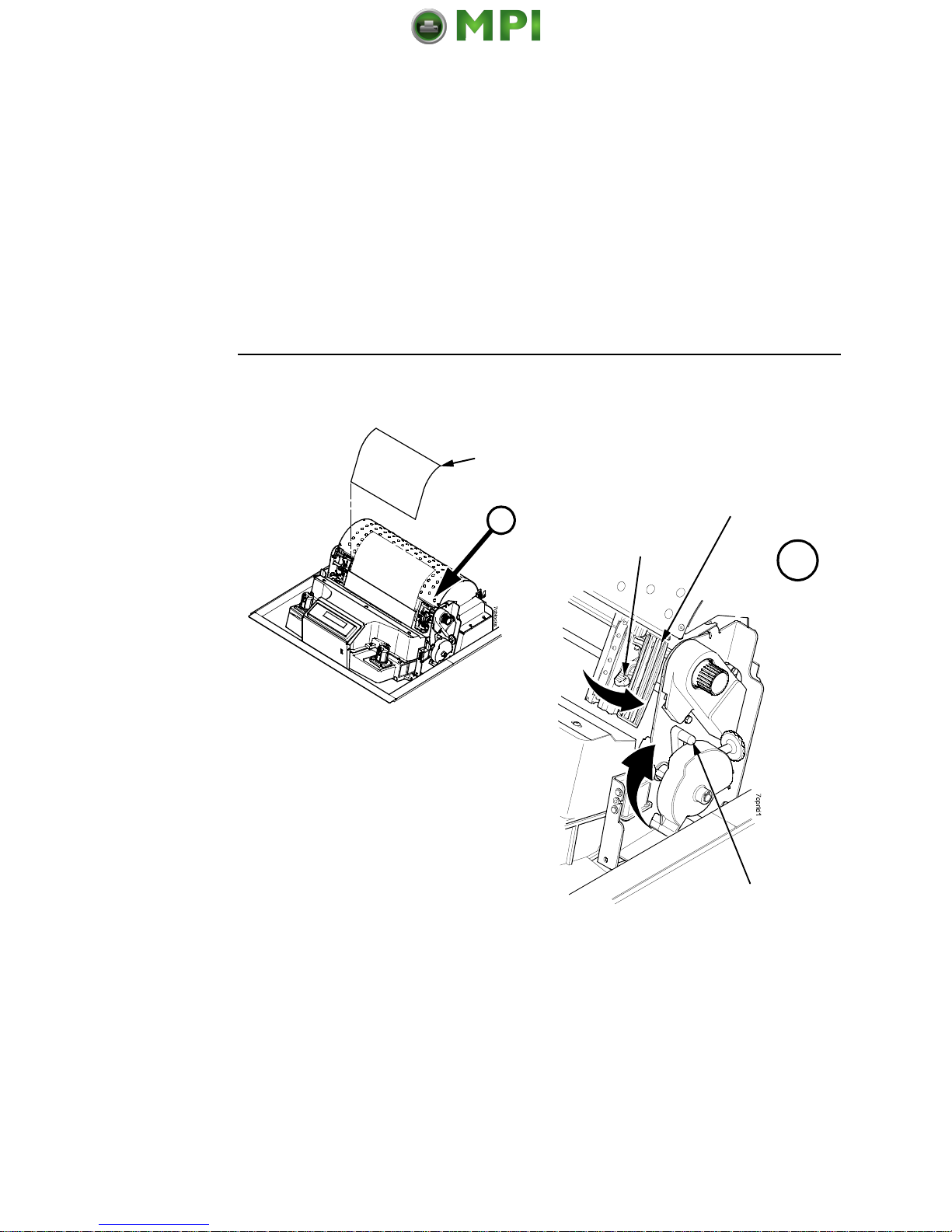
Figure 3. Removing the Sample Configuration Printout
2. Open the blue tractor doors.
3. Move the tractor locks to the middle position to unlock them.
4. Raise the platen lever to the fully open (raised) position.
5. Remove the envelope containing the sample configuration
printout.
6. Store the envelope in the pouch attached to the left interior side
of the cabinet.
7. Remove the cardboard packing.
Envelope
Platen Lever
Blue Tractor
Door (2)
A
A
Blue Tractor
Lock (2)
Mantenimiento Periféricos Informáticos SL C/Canteras, 15 28860 Paracuellos de Jarama Tel: 00 34 917481604 WEB: https://mpi.com.es
Page 11

11
Figure 4. Removing the Hammer Bank Protective Foam
8. Remove the hammer bank protective foam between the ribbon
mask and the platen.
Hammer Bank
Protective Foam
Remove Packing Materials
Mantenimiento Periféricos Informáticos SL C/Canteras, 15 28860 Paracuellos de Jarama Tel: 00 34 917481604 WEB: https://mpi.com.es
Page 12

Remove Packing Materials
12
Figure 5. Removing the Platen Protective Foam
9. Rotate the platen protective foam toward the front of the printer
and out from under the support shaft.
10. Remove the platen protective foam.
Platen Protective
Foam
Mantenimiento Periféricos Informáticos SL C/Canteras, 15 28860 Paracuellos de Jarama Tel: 00 34 917481604 WEB: https://mpi.com.es
Page 13

13
Figure 6. Removing the Six Wooden Blocks
11. Remove the six wooden blocks.
Wooden Block (6)
Wooden Block
Wooden Block
Wooden Block
Wooden Block
Wooden Block
Remove Packing Materials
Mantenimiento Periféricos Informáticos SL C/Canteras, 15 28860 Paracuellos de Jarama Tel: 00 34 917481604 WEB: https://mpi.com.es
Page 14

Adjust The Paper Supports
14
Adjust The Paper Supports
Figure 7. Adjusting Paper Supports
Squeeze the paper support tabs and slide the blue paper supports
inward until each one is approximately four inches from its
corresponding blue tractor door.
Blue Paper Support (2)
Blue Tractor
Door (2)
Paper Support
Tab (2)
A
A
Mantenimiento Periféricos Informáticos SL C/Canteras, 15 28860 Paracuellos de Jarama Tel: 00 34 917481604 WEB: https://mpi.com.es
Page 15
15
Release The Paper Chains – Cabinet Model
NOTE: Steps 1– 3 in this section are for the passive stacker. If you
have the power paper stacker installed, skip this procedure
and go to “Remove The Shipping Restraints From The
Power Paper Stacker (If Equipped)” on page 17.
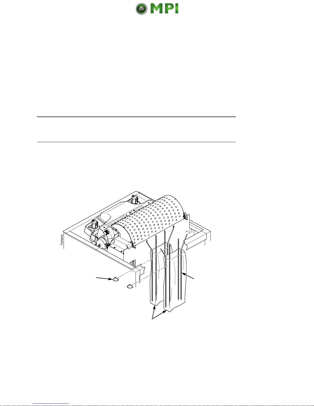
Figure 8. Releasing the Paper Stacking Chains
1. Open the cabinet rear door.
2. Cut the tie wraps and release the paper stacking chains from
the bags at the top rear of the printer frame. Remove the tie
wraps and bags.
3. Make sure each chain hangs freely with no kinks or knots.
Tie Wrap (2)
Paper Chain (8)
Bag (2)
Release The Paper Chains – Cabinet Model
Mantenimiento Periféricos Informáticos SL C/Canteras, 15 28860 Paracuellos de Jarama Tel: 00 34 917481604 WEB: https://mpi.com.es
Page 16
Remove Tags – Cabinet Model
16
Remove Tags – Cabinet Model
NOTE: If you have the power paper stacker installed, skip this
procedure and go to “Remove The Shipping Restraints
From The Power Paper Stacker (If Equipped)” on page 17.
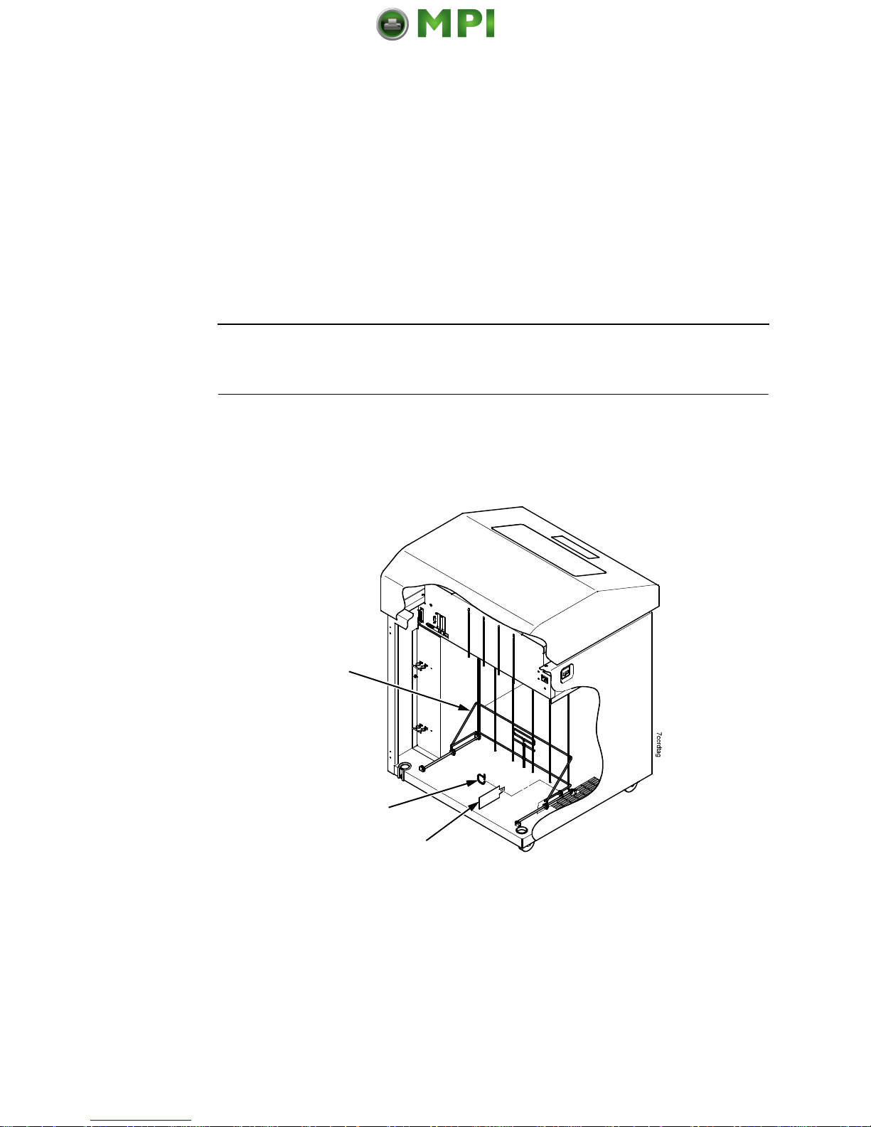
Figure 9. Removing Tags from the Cabinet Models
1. Remove the tie wrap attached to the passive stacker paper
fence. The tie wrap is marked with a large, red tag.
2. Close the cabinet rear door.
Passive Stacker
Paper Fence
(if equipped)
Tie Wrap
Red Tag
Mantenimiento Periféricos Informáticos SL C/Canteras, 15 28860 Paracuellos de Jarama Tel: 00 34 917481604 WEB: https://mpi.com.es
Page 17

17
Remove The Shipping Restraints From
The Power Paper Stacker (If Equipped)
This section applies only to printers with the power stacker
installed.
Special packaging protects the power stacker mechanisms from
damage during shipment. This section describes how to remove
the shipping restraints before you operate the printer.
Save the packaging materials. You will need to reinstall them if you
decide to move or ship the printer. To reinstall the packaging
materials, reverse the steps in this section.
IMPORTANT
To avoid shipping damage, install the shipping restraints
whenever you move or ship the printer.
Remove The Shipping Restraints From The Power Paper Stacker (If Equipped)
Mantenimiento Periféricos Informáticos SL C/Canteras, 15 28860 Paracuellos de Jarama Tel: 00 34 917481604 WEB: https://mpi.com.es
Page 18
Remove The Shipping Restraints From The Power Paper Stacker (If Equipped)
18
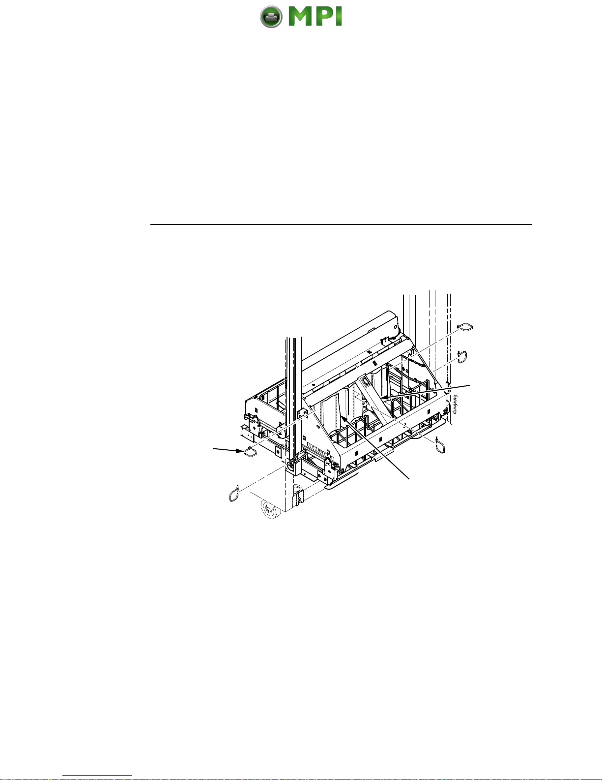
Figure 10. Removing the Shipping Restraints
1. Open the rear door panel.
2. Remove the five tie wraps.
3. Raise the power paper stacker frame to its highest position by
pulling up on the elevator lift handle.
4. Remove the plastic bags from the paper chains.
Tie Wrap (5)
Plastic Bag (3)
Elevator Lift
Handle
Mantenimiento Periféricos Informáticos SL C/Canteras, 15 28860 Paracuellos de Jarama Tel: 00 34 917481604 WEB: https://mpi.com.es
Page 19

19
Figure 11. Replacing the Paper Tent
5. Remove the tape holding the paper tent.
6. Place the paper tent onto the pull-out drawer.
Paper Tent
Tape
Remove The Shipping Restraints From The Power Paper Stacker (If Equipped)
Mantenimiento Periféricos Informáticos SL C/Canteras, 15 28860 Paracuellos de Jarama Tel: 00 34 917481604 WEB: https://mpi.com.es
Page 20

Attach The Control Panel Overlay
20
Attach The Control Panel Overlay
Figure 12. Attaching Control Panel Overlay
1. Choose the overlay label in the appropriate language.
2. Open the printer cover.
3. Peel the protective backing off the overlay and the blue tape
from the window.
4. Press the overlay into place.
Overlay Label
Mantenimiento Periféricos Informáticos SL C/Canteras, 15 28860 Paracuellos de Jarama Tel: 00 34 917481604 WEB: https://mpi.com.es
Page 21

21
Cabinet Model
Connect The Interface And Power Cables
Cabinet Model
Interface Connections
Figure 13. Routing the I/O Cable and AC Power Cable
1. Make sure the printer power switch is set to O (Off).
2. Open rear cabinet door and locate the cable routing notch in
the lower left corner of the back of the cabinet.
Cable-Routing
Notches
I/O Connectors
Power
Switch
AC Power
Connection
I/O Cover
Upper and
Lower
Standoffs
Connect The Interface And Power Cables
Mantenimiento Periféricos Informáticos SL C/Canteras, 15 28860 Paracuellos de Jarama Tel: 00 34 917481604 WEB: https://mpi.com.es
Page 22

Connect The Interface And Power Cables
22
Figure 14. Routing the I/O Cable
3. Hold the I/O cable below its connector and gently push the
cable through the opening in the grommet seated in the notch.
4. Pull the cable up through the notch until it reaches the I/O plate.
Attach the cable connector to the desired printer interface
connector as shown on page 23. (Interface connections are
shown on page 23.)
5. Secure the cable to the printer using the upper and lower
standoffs.
6. Guide the power cable up through the hole in the lower right
back corner of the cabinet (see Figure 13). Thread the power
cable inside the bracket where the gas spring is attached.
7. Plug the power cord into the printer AC power connector, then
into the AC power outlet.
IMPORTANT
Printer power should be supplied from a separate AC circuit
protected at 10 amperes for 100 - 120 volts or 5 amperes for
200 - 240 volts at 50 or 60 Hertz.
8. Turn the printer on.
9. Continue on page 25.
I/O Cable
Grommet
Mantenimiento Periféricos Informáticos SL C/Canteras, 15 28860 Paracuellos de Jarama Tel: 00 34 917481604 WEB: https://mpi.com.es
Page 23
23
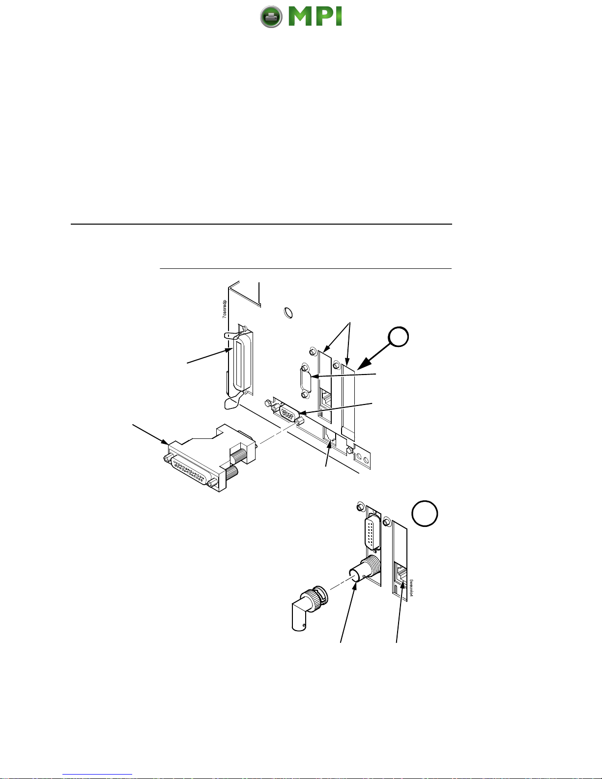
Interface Connections (Cabinet And Pedestal)
Interface Connections (Cabinet And Pedestal)
Figure 15. Cabinet Model Interface Connections
1. Remove the cover from the I/O connector you have selected.
2. Attach the I/O cable connector to the printer interface
connector.
RS-422
(if installed)
Diagnostic
Ethernet option (if installed)
or Coax/Twinax (if installed)
9 Pin STD
Serial RS-232
Centronics Parallel
9 Pin to 25 Pin STD
Serial Adapter
Network
10/100 Base-T
Coax/Twinax
A
A
Mantenimiento Periféricos Informáticos SL C/Canteras, 15 28860 Paracuellos de Jarama Tel: 00 34 917481604 WEB: https://mpi.com.es
Page 24

Connect The Interface And Power Cables
24
Pedestal Model
Figure 16. Attaching the AC Power Cable
1. Make sure the printer power switch is set to O (Off).
2. Remove the cover from the I/O connector you have selected.
3. Attach the I/O cable connector to the printer interface connector
(page 23).
4. Plug the power cord into the printer AC power connector, then
into the AC power outlet.
IMPORTANT
Printer power should be supplied from a separate AC circuit
protected at 10 amperes for 100 - 120 volts or 5 amperes for
200 - 240 volts at 50 or 60 Hertz.
5. Turn the printer on.
6. Continue on page 25.
Power Switch
AC Power Connector
Mantenimiento Periféricos Informáticos SL C/Canteras, 15 28860 Paracuellos de Jarama Tel: 00 34 917481604 WEB: https://mpi.com.es
Page 25

25
Load The Ribbon
Install The Ribbon And Paper
The following sections describe how to install ribbon and load
paper.
Load The Ribbon
The line matrix printer requires ribbons that work with the Integrated
Print Management System. Earlier models and other legacy
ribbons do not provide this support and will not work.
Figure 17. Preparing to Load the Ribbon
1. Make sure the printer cover is open.
2. Raise the platen lever as far as it will go.
3. Close the blue tractor doors.
Blue Tractor
Door (2)
Platen Lever
Mantenimiento Periféricos Informáticos SL C/Canteras, 15 28860 Paracuellos de Jarama Tel: 00 34 917481604 WEB: https://mpi.com.es
Page 26

Install The Ribbon And Paper
26
Figure 18. Loading the Ribbon
4. Place the full spool on the right hub. Be sure the ribbon feeds
off the outside of the spool.
5. Press the spool down until it snaps into place.
IMPORTANT
The full spool has a barcode label on the bottom side and a
date code label on the top. Once the sensor automatically
reads and logs the ribbon barcode, the Integrated Print
Management System starts to track ribbon usage.
If you remove the ribbon during the course of its life and want
to re-install the same ribbon, be sure to place the same spools
on the correct hubs. Do not reverse the spools. Be sure to
re-install the spool with the date code label on the top onto the
right hand hub.
Right Hub
Spool
Mantenimiento Periféricos Informáticos SL C/Canteras, 15 28860 Paracuellos de Jarama Tel: 00 34 917481604 WEB: https://mpi.com.es
Page 27

27
Load The Ribbon
Figure 19. Threading the Ribbon Around the Ribbon Guide
6. Thread the ribbon around the ribbon guide and along the ribbon
path. Be sure to thread the ribbon between the hammer bank
cover and the ribbon mask.
7. Place the empty spool on the left hub.
8. Press the spool down until it snaps into place.
9. Turn the left spool by hand to make sure the ribbon tracks
correctly in the ribbon path and around the ribbon guides.
Ribbon Guide
(both sides)
Left Hub
Ribbon Spool
Ribbon Mask
A
A
Hammer
Bank Cover
Ribbon Loading
Instructions
(for future reference)
Mantenimiento Periféricos Informáticos SL C/Canteras, 15 28860 Paracuellos de Jarama Tel: 00 34 917481604 WEB: https://mpi.com.es
Page 28

Install The Ribbon And Paper
28
Load The Paper (Standard Configuration)
When you start this procedure, verify that the printer cover is open,
the platen lever is raised, and the blue tractor doors are open. See
“Printer Component Locations” on page 8.
Figure 20. Aligning the Paper Supply
1. Prepare the paper supply:
Cabinet Model
a. Open the front door of the printer cabinet.
b. Place the paper supply inside the printer, on the floor of the
cabinet.
c. Align the paper supply with the front label on the floor of the
printer.
d. Ensure that the paper pulls freely from the box.
e. Feed the paper up through the paper slot.
NOTE: The 2000 line per minute model has a metal paper guide.
Load the paper on top of this guide.
Label
Mantenimiento Periféricos Informáticos SL C/Canteras, 15 28860 Paracuellos de Jarama Tel: 00 34 917481604 WEB: https://mpi.com.es
Page 29

29
Load The Paper (Standard Configuration)
Figure 21. Feeding the Paper Through the Paper Slot
Pedestal Model
a. Place the paper supply on the floor in front of the printer, or
on the optional paper shelf, if attached.
b. Ensure that the paper pulls freely from the box.
NOTE: Be sure the paper feeds between the two wire guides.
2. Hold the paper in place with one hand (to prevent it from
slipping down through the paper slot) while pulling it through
from above with your other hand.
3. Pull the paper above and behind the ribbon mask, which is a
silver metal strip.
Paper
Slot
Cabinet Model Pedestal Model
Paper Slot
Metal Paper Guide
(MX1200 or
MX1200+ only)
Wire
Guide (2)
Mantenimiento Periféricos Informáticos SL C/Canteras, 15 28860 Paracuellos de Jarama Tel: 00 34 917481604 WEB: https://mpi.com.es
Page 30

Install The Ribbon And Paper
30
Figure 22. Loading Paper onto the Left Tractor Sprockets
4. Load the paper on the left tractor sprockets.
5. Close the tractor door.
Paper
Left Tractor Door
Left Tractor Lock
Mantenimiento Periféricos Informáticos SL C/Canteras, 15 28860 Paracuellos de Jarama Tel: 00 34 917481604 WEB: https://mpi.com.es
Page 31

31
Load The Paper (Standard Configuration)
CAUTION
To avoid damage to the printer caused by printing on the
platen, always position the left tractor unit directly to the left of
the “1” mark on the paper scale.
Figure 23. Using the Paper Scale as a Guide
6. If adjustment is necessary:
a. Unlock the left tractor.
b. Slide the tractor until it is directly to the left of the number
“1” on the paper scale and lock it. You can also use the
paper scale to count columns.
c. Lock the left tractor.
Paper
Paper Scale
Tractor
Tractor Splined Shaft
Mantenimiento Periféricos Informáticos SL C/Canteras, 15 28860 Paracuellos de Jarama Tel: 00 34 917481604 WEB: https://mpi.com.es
Page 32

Install The Ribbon And Paper
32
Figure 24. Loading the Paper onto the Right Tractor Sprockets
7. Unlock the right tractor.
8. Load the paper onto the right tractor sprockets.
9. Close the tractor door.
10. Make sure the leading edge of the first sheet of paper is parallel
to the top of the tractors. If the paper is misaligned, reload it
onto the tractor sprockets until its edge is parallel to the splined
shaft.
11. Slide the right tractor to remove paper slack or to adjust for
various paper widths.
12. Lock the right tractor.
Right Tractor Door
Mantenimiento Periféricos Informáticos SL C/Canteras, 15 28860 Paracuellos de Jarama Tel: 00 34 917481604 WEB: https://mpi.com.es
Page 33

33
Load The Paper (Standard Configuration)
Figure 25. Set the Platen Lever based on the Paper Thickness
13. Raise the platen lever all the way.
14. Turn the vertical position knob to feed the paper up into the
paper guide assembly.
15. Turn the platen stop knob clockwise or counterclockwise to
match the paper thickness. (The A-B-C scale corresponds
approximately to 1-, 3-, and 6-part paper thickness).
NOTE: The platen stop allows you to set an optimum and
consistent thickness that is not affected when opening and
closing the platen lever.
16. Lower the platen lever until it stops.
17. If necessary, press ON LINE/CLEAR to remove the “LOAD
PAPER” fault message from the display.
Platen Lever
Vertical Position
Knob
Platen Stop
Knob
A
A
Platen Stop
Paper Thickness
Indicator
Mantenimiento Periféricos Informáticos SL C/Canteras, 15 28860 Paracuellos de Jarama Tel: 00 34 917481604 WEB: https://mpi.com.es
Page 34

Install The Ribbon And Paper
34
18. Press the PAPER ADVANCE key several times to make sure
the paper feeds properly beyond the tractors over the lower
paper guide. Feed sufficient paper to ensure the paper stacks
correctly.
19. Close the printer cover.
20. Close the cabinet door.
21. Press ON LINE/CLEAR to place the printer online and resume
printing.
NOTE: For cabinet models with the power paper stacker installed,
go to “Power Paper Stacker Option” on page 39. For all
other cabinet models, go to “Set The Top-Of-Form” on
page 35.
For paper exiting options on the pedestal model, see
Figure 40 on page 50.
Mantenimiento Periféricos Informáticos SL C/Canteras, 15 28860 Paracuellos de Jarama Tel: 00 34 917481604 WEB: https://mpi.com.es
Page 35

35
Load The Paper (Standard Configuration)
Set The Top-Of-Form
Every time you load paper, you set the top-of-form (TOF) location.
This procedure must be performed the first time paper is introduced
into the printer, and every time new paper is loaded.
1. Press ON LINE/CLEAR to place the printer in offline mode.
The LCD will display “OFFLINE / QUICK SET-UP.”
Figure 26. Raising the Platen Lever
2. Raise the platen lever as far as it will go. This allows you to turn
the vertical position knob freely to align the top-of-form.
Vertical Position Knob
Platen Lever
Set The Top-Of-Form
Mantenimiento Periféricos Informáticos SL C/Canteras, 15 28860 Paracuellos de Jarama Tel: 00 34 917481604 WEB: https://mpi.com.es
Page 36

Set The Top-Of-Form
36
Figure 27. Aligning the First Print Line with the TOF Indicator
3. Locate the TOF indicator. It is a small tab located on both the
right and left tractor doors.
4. Turn the vertical position knob to align the top of the first print
line with the TOF indicator. For best print quality, it is
recommended that the top-of-form be set at least one print line
or more below the perforation.
NOTE: For exact positioning, press the VIEW/EJECT key to move
the last data printed to the tractor area for viewing. While in
View mode “Printer in View” displays. Press the Up or
Down Arrow keys to move the paper vertically in small
increments. Pressing the VIEW/EJECT key a second time
moves the paper back to the adjusted print position. The
key works both online and offline provided that the printer is
in View mode. (This procedure is applicable for both the
cabinet and pedestal models.)
TOF Indicator
Perforation
Vertical
Position
Knob
Mantenimiento Periféricos Informáticos SL C/Canteras, 15 28860 Paracuellos de Jarama Tel: 00 34 917481604 WEB: https://mpi.com.es
Page 37

37
Load The Paper (Standard Configuration)
Figure 28. Closing the Platen Lever
5. Lower the platen lever until it stops.
6. Press ON LINE/CLEAR to remove any fault messages (such
as “LOAD PAPER”) from the message display.
7. Press SET TOF. The top-of-form position you have set moves
down to the print position.
8. Press ON LINE/CLEAR to place the printer in online mode.
Platen Lever
Set The Top-Of-Form
Mantenimiento Periféricos Informáticos SL C/Canteras, 15 28860 Paracuellos de Jarama Tel: 00 34 917481604 WEB: https://mpi.com.es
Page 38

Adjust The Passive Paper Stacker – Cabinet Model
38
Adjust The Passive Paper Stacker – Cabinet Model
Figure 29. Adjusting the Passive Stacker
1. Pull the passive stacker handle up.
2. Move the passive stacker forward or back for proper paper
adjustment.
3. Release the passive stacker handle.
4. Close the cabinet door.
Passive Stacker
Handle
A
A
Mantenimiento Periféricos Informáticos SL C/Canteras, 15 28860 Paracuellos de Jarama Tel: 00 34 917481604 WEB: https://mpi.com.es
Page 39

39
Power Paper Stacker Component Locations
Power Paper Stacker Option
This section explains how to set up and use the optional power
paper stacker. The power paper stacker mechanically directs the
paper from the printer to the paper stacker.
NOTE: If your printer does not have either of these options, go to
“Checking The Paper Feed – Cabinet Model” on page 45.
Power Paper Stacker Component Locations
Familiarize yourself with the names and locations of the
components, shown in Figure 30, before operating the paper
stacker.
Figure 30. Power Stacker Component Locations
Pinch Rollers
Paper Throat
Rear Control
Panel
Wire Paper
Tent
Paddle Shaft
Bearing Bracket
Paper Length
Indicator
Elevator Lift
Handle
Elevator Disable
Switch
Mantenimiento Periféricos Informáticos SL C/Canteras, 15 28860 Paracuellos de Jarama Tel: 00 34 917481604 WEB: https://mpi.com.es
Page 40

Power Paper Stacker Option
40
Setting Up The Power Paper Stacker
Figure 31. Use the Rear Control Panel to Set Up the Power Stacker
1. Using the rear control panel, press ON LINE/CLEAR to take
the printer offline.
2. Grasp the elevator lift handle, press the elevator disable switch,
and lift the elevator to the top of its travel.
A
A
Stacker Up
Stacker
Down
Paper
Advance
Elevator Disable
Switch
Elevator Lift Handle
Mantenimiento Periféricos Informáticos SL C/Canteras, 15 28860 Paracuellos de Jarama Tel: 00 34 917481604 WEB: https://mpi.com.es
Page 41

41
Setting Up The Power Paper Stacker
Figure 32. Power Stacker Components
3. Make sure the wire paper tent is fitted in the pull out paper tray
in the base of the stacker.
Wire Paper Tent
Paper
Stacker Rails
Mantenimiento Periféricos Informáticos SL C/Canteras, 15 28860 Paracuellos de Jarama Tel: 00 34 917481604 WEB: https://mpi.com.es
Page 42

Power Paper Stacker Option
42
Figure 33. Setting the Paper Length
4. Set the desired paper length (5 to 12 inch range), as follows:
Grasping the paddle shaft, push or pull towards the front or the
rear of the printer, setting the desired paper length by aligning
the indicator notch on the bearing bracket with the paper length
indicator.
5. Press STACKER DOWN.
A
A
Paddle Shaft
Bearing Bracket
Paper Length Indicator
Mantenimiento Periféricos Informáticos SL C/Canteras, 15 28860 Paracuellos de Jarama Tel: 00 34 917481604 WEB: https://mpi.com.es
Page 43

43
Loading And Starting The Power Paper Stacker
Loading And Starting The Power Paper Stacker
Figure 34. Stacking Sheets of Paper on the Wire Paper Tent
1. Using the rear control panel, press the PAPER ADVANCE key
and hand feed the paper in the paper throat. Continue to
advance the paper until it reaches the wire tent and there is an
excess of 3 to 5 pages in the stacker. Be certain the paper
passes through the paper stacker throat.
2. Stack the 3 to 5 sheets of paper on top of the wire paper tent,
making sure the paper lies with the natural fold.
NOTE: When the guides are set for narrow paper, the paper tent
limits downward travel, causing motor stalls. If this occurs,
remove the paper tent.
Wire Paper Tent
Mantenimiento Periféricos Informáticos SL C/Canteras, 15 28860 Paracuellos de Jarama Tel: 00 34 917481604 WEB: https://mpi.com.es
Page 44

Power Paper Stacker Option
44
Figure 35. Returning the Stacker Frame to its Proper Position
3. Press the ON LINE/CLEAR key, from either the front or rear
control panel, to put the printer in the online state. The stacker
frame then returns to its proper position for printing.
4. Check that the paper is still centered between the paper
guides.
5. Close the cabinet rear door.
Rear Control
Panel
Paper Guide
Mantenimiento Periféricos Informáticos SL C/Canteras, 15 28860 Paracuellos de Jarama Tel: 00 34 917481604 WEB: https://mpi.com.es
Page 45

45
Loading And Starting The Power Paper Stacker
Checking The Paper Feed – Cabinet Model
Figure 36. Side View of the Cabinet Model Showing Paper Feed Route
1. Check that the paper feeds correctly.
2. Press the Form Feed key several times to ensure that the
paper feeds properly beyond the tractors and over the paper
guide assembly.
3. Ensure that the paper folds the same way in the stacking area
as it does in the supply area.
4. Close the front and rear cabinet doors, if the length of the form
allows.
Paper Guide
Checking The Paper Feed – Cabinet Model
Mantenimiento Periféricos Informáticos SL C/Canteras, 15 28860 Paracuellos de Jarama Tel: 00 34 917481604 WEB: https://mpi.com.es
Page 46

Attach The Input Paper Shelf And Output Basket – Pedestal Model
46
Attach The Input Paper Shelf And Output Basket –
Pedestal Model
Figure 37. Pedestal Model With Output Basket Attachment
A
A
Output
Basket
Screw
Ground Wire
Optional
Input Paper
Shelf
Wire Form
Back Stop
Mantenimiento Periféricos Informáticos SL C/Canteras, 15 28860 Paracuellos de Jarama Tel: 00 34 917481604 WEB: https://mpi.com.es
Page 47

47
Loading And Starting The Power Paper Stacker
1. Squeeze the paper support tabs and slide the two blue paper
supports toward the center of the support shaft. Position them
so that they divide the space between the tractors into three
approximately equal segments.
2. Place the output basket in the holes in the back of the printer.
3. Screw the ground wire attached to the output basket to the
printer.
4. Squeeze the wire form back stop and place it between the wire
frames of the output basket.
NOTE: The wire form back stop helps to hold the printed paper in
place.
5. Place the input paper shelf (optional feaure) in the holes in the
front of the pedestal base.
Attach The Input Paper Shelf And Output Basket – Pedestal Model
Mantenimiento Periféricos Informáticos SL C/Canteras, 15 28860 Paracuellos de Jarama Tel: 00 34 917481604 WEB: https://mpi.com.es
Page 48

Quick Access – Pedestal Model
48
Quick Access – Pedestal Model
The quick access cover on the pedestal model allows the paper to
exit through the top of the printer.
Figure 38. Paper Exiting the Top of the Printer (Cover Removed)
Paper
Quick Access
Cover
Paper
Tear Bar
Mantenimiento Periféricos Informáticos SL C/Canteras, 15 28860 Paracuellos de Jarama Tel: 00 34 917481604 WEB: https://mpi.com.es
Page 49

49
Loading And Starting The Power Paper Stacker
Top Paper Exit
Figure 39. The Quick Access Cover on the Pedestal Model
1. Open the pedestal printer top cover.
2. Unscrew the blue captive screws securing the cover insert to
the top cover.
3. Remove the cover insert and place to the side. Removal of the
cover insert allows you to feed the paper through the top cover,
thus exiting the top of the printer.
NOTE: Do not discard the cover insert. You may use it to close the
paper slot exit and have the paper exit the rear of the
printer.
4. Raise the quick access paper deflector.
5. Rotate the thumbwheel to angle the quick access paper
deflector.
6. Load the paper and feed it through the paper exit slot on the top
of the printer cover.
7. Align the perforation and tear the paper off along the tear bar.
Top Cover
Quick Access
Cover
Quick Access
Paper Deflector
Paper Exit Slot
Blue Captive
Screw (2)
Blue Deflector
Thumbwheel
Quick Access – Pedestal Model
Mantenimiento Periféricos Informáticos SL C/Canteras, 15 28860 Paracuellos de Jarama Tel: 00 34 917481604 WEB: https://mpi.com.es
Page 50

Checking The Paper Feed – Pedestal Model
50
Checking The Paper Feed – Pedestal Model
Figure 40. Side View of the Pedestal Model Showing Paper Feed Routes
NOTE: When using the top exit paper path, paper cannot be
stacked. Paper is intended to be removed after each print
job is completed.
• For rear paper exit: Press the Paper Advance key several
times to ensure that the paper feeds properly beyond the
tractors, over the paper guide assembly, and through the paper
exit slot in the rear of the cabinet. Ensure that the paper folds
the same way in the stacking area as it does in the supply area.
• For top paper exit: Press the Paper Advance key several
times to ensure that the paper feeds properly beyond the
tractors, over the paper guide assembly, and through the paper
exit slot.
Rear Exit Top Exit
Mantenimiento Periféricos Informáticos SL C/Canteras, 15 28860 Paracuellos de Jarama Tel: 00 34 917481604 WEB: https://mpi.com.es
Page 51

51
Loading And Starting The Power Paper Stacker
The Control Panel
Figure 41. Control Panel
For more information on control panel keys and functions, refer to
Chapter 3 in the User’s Manual.
Ribbon Life Indicator
Indicates the remaining life of the currently installed ribbon. This
feature issues a warning when remaining life drops below 2% and
will stop printing at 0%.
NOTE: The default setting for this feature should match the
requirements for most applications; no special setup is
needed. If your particular application requires darker
printing or can tolerate lighter printing, this end point can be
adjusted as appropriate. Please refer to the section on
setting Ribbon End Point in the Printer Control Menu
section of the User’s Manual.
SET TOF
PRT CONFIG
JOB SELECT
ENTER
ON LINE/CLEAR
PAPER ADVANCE
VIEW/EJECT
CANCEL
Message Display
Status Indicator
Circular
Pad
ONLINE <PGL>
RIBBON LIFE = 100%
Emulation
Ribbon Life
Indicator
The Control Panel
Mantenimiento Periféricos Informáticos SL C/Canteras, 15 28860 Paracuellos de Jarama Tel: 00 34 917481604 WEB: https://mpi.com.es
Page 52

Printer Self-Test
52
When printing stops at 0%, and if immediately
changing the ribbon is not convenient, you can place
the printer back online and printing will resume for a
short period.
Printer Self-Test
Each time you power on the printer, it executes a self-test. The
default power-up state is online. When the self-test completes and
the software has initialized successfully, the status indicator light
turns on, indicating that the printer is online. The ribbon life
remaining appears in the display.
Quick Setup Menu
The Quick Setup menu allows access to the most frequently
changed or selected parameters during the installation of the
printer. To familiarize yourself with the Quick Setup menu, navigate
through the menu by doing the following:
1. Press the ON LINE/CLEAR key.
2. Press the Up Arrow and Down Arrow keys simultaneously to
unlock the ENTER key.
3. Press the Right Arrow key to navigate through the menus.
In most cases, the factory default settings can be used. If you want
to change a setting, use the arrow keys to display the desired
setting, then press ENTER.
Mantenimiento Periféricos Informáticos SL C/Canteras, 15 28860 Paracuellos de Jarama Tel: 00 34 917481604 WEB: https://mpi.com.es
Page 53

53
Loading And Starting The Power Paper Stacker
QUICK SETUP
Host
Interface
Device ID
Adapter
Address
1
WLAN
Address
Active IGP
EMUL
4
PGL SFCC
10
Auto Switching*
Centronics
Dataproducts
Serial
IEEE 1284
Coax
1
Twinax
1
Ethernet
1
IPDS*
5225
4234-2
IP Address
2
Subnet Mask
2
Gateway Address
2
MAC Address
2
DHCP
2
IP Address
3
Subnet Mask
3
Gateway Address
3
MAC Address
3
DHCP
3
IGP/PGL*
IGP/VGL
4
7E*
1-FF
* = Factory Default
6
If LP+ is selected
1
If installed
7
If ANSI is installed
2
If Enet is selected
8
If LG is installed
3
If Wireless is selected
9
If PCL-II is installed
4
If VGL is enabled
10
If PGL is selected
5
If VGL is selected
Printer
Protocol
P-Series*
P-Series XQ
Serial Matrix
Proprinter XL
Epson FX
Form
Length
6
Funct. of Lines
66 lines*
1-192 lines
Ethernet
Address
1
IP Address
2
Subnet Mask
2
Gateway Address
2
MAC Address
2
DHCP
2
Form
Width
6
Funct. of CPI
132 characters*
1-272 characters
VGL SFCC
5
5E*
Select CPI
10.0 CPI*
12.0 CPI
13.3 CPI
15.0 CPI
17.1 CPI
20.0 CPI
Quick Setup Menu
Mantenimiento Periféricos Informáticos SL C/Canteras, 15 28860 Paracuellos de Jarama Tel: 00 34 917481604 WEB: https://mpi.com.es
Page 54

Quick Setup Menu
54
Host Interface
The Host Interface menu enables you to select and configure
interfaces between the printer and your host computer.
Horiz
Forms
8
Left Mrg 0.00*
(0-198)
Top Mrg 0/6*
(0-198)
Page Length
Rep
9
Inches/Page*
Lines/Page
Max Line
Width
9
13.2 Inches*
13.6 Inches
Save Config
1*
2 - 8
QUICK SETUP
(continued)
* = Factory Default
6
If LP+ is selected
1
If installed
7
If ANSI is installed
2
If Enet is selected
8
If LG is installed
3
If Wireless is selected
9
If PCL-II is installed
4
If VGL is enabled
5
If VGL is selected
Margins
7
Left Margin
Right Margin
Top Margin
Bottom Margin
Form
Length
7
Funct. of Lines
66 Lines*
(1-192)
Form
Width
7
Funct. of CPI
136 Characters*
(1-272)
Vert
Forms
8
Bot. Frm 66/6*
(0-198)
Top Mrg 0/6*
(0-198)
Power Up
Config
Factory*
1 - 8
P-Series
SFCC
6
1*
00-7F
Select CPI
6.0 LPI*
8.0 LPI
10.3 LPI
Ribbon End
Point
Darker +3
Darker +2
Darker +1
Normal*
Lighter -1
Lighter -2
Lighter -3
Lighter -4
Lighter -5
Mantenimiento Periféricos Informáticos SL C/Canteras, 15 28860 Paracuellos de Jarama Tel: 00 34 917481604 WEB: https://mpi.com.es
Page 55

55
Loading And Starting The Power Paper Stacker
Device ID
This parameter defines the printer emulation as IPDS, 4234-2 or
5225. After the emulation has been changed, a POR status is sent
to the host. IPDS is the default.
Ethernet Address
• IP Address. A numeric address such as 123.45.61.23 which
identifies a printer or server in a LAN or WAN.
• Subnet Mask. A binary value used to divide IP networks into
smaller subnetworks or subnets. This mask is used to help
determine whether IP packets need to be forwarded to other
subnets.
• Gateway Address. A gateway address is the IP address of a
hardware device (gateway) that translates data between two
incompatible networks, which can include protocol translation.
• MAC Address. This menu item is the Manufacturer’s Assigned
Number, and is unique for each printer. It is read-only.
• DHCP. You can enable/disable the DHCP protocol using this
option, but consult your administrator for the appropriate
setting.
Active IGP Emulation
The Active Emulation menu enables you to activate either the PGL
or VGL emulation.
Ribbon End Point
This parameter adjusts the point at which the system will declare
the ribbon as being expended. The life count will always be from
100% to 0%, but if a darker setting is selected 0% will be reached
more quickly. If a lighter setting is selected, the system will extend
the time it takes to reach 0%.
Quick Setup Menu
Mantenimiento Periféricos Informáticos SL C/Canteras, 15 28860 Paracuellos de Jarama Tel: 00 34 917481604 WEB: https://mpi.com.es
Page 56

Quick Setup Menu
56
Save Config
This option allows you to save up to eight configurations to meet
different print job requirements. This eliminates the need to change
the parameter settings for each new job. The configurations are
stored in memory and will not be lost if you turn off the printer. If the
Protect Configs. parameter is enabled, the new configuration will
not be saved unless the existing configuration has been deleted
first. The factory default configuration cannot be changed.
Power Up Config
This option allows you to specify which of the nine configurations
(Factory or 1-8) will be the power-up configuration.
Mantenimiento Periféricos Informáticos SL C/Canteras, 15 28860 Paracuellos de Jarama Tel: 00 34 917481604 WEB: https://mpi.com.es
Page 57

57
Loading And Starting The Power Paper Stacker
Print A Test Page
Now you will print the printer’s current configuration by following the
instructions below:
Step Press Result Notes
1. Make sure the printer is on.
2.
3. Allows you to make
configuration changes.
4.
5.
6.
7.
ON LINE/CLEAR
OFFLINE
QUICK SETUP
+
ENTER SWITCH
UNLOCKED
OFFLINE
QUICK SETUP
UNTIL
OFFLINE
CONFIG. CONTROL
Config. Control
Load Config.
UNTIL
Config. Control
Print Config.
Print Config.
Current Short*
Print A Test Page
Mantenimiento Periféricos Informáticos SL C/Canteras, 15 28860 Paracuellos de Jarama Tel: 00 34 917481604 WEB: https://mpi.com.es
Page 58

Print A Test Page
58
Congratulations! You have unpacked the printer, loaded ribbon and
paper, and printed a test page. The next step is to configure the
printer for use with the host computer. Everything you need to know
about configuring the printer is in the User's Manual, which is on the
CD-ROM that comes with this booklet.
8. Press until the desired
option displays.
9. The configuration listing
begins to print, then the
printer goes back offline.
10. Carefully tear off the configuration printout.
11. Locks the ENTER key.
12.
13. Store the printout in a safe place. The printer is ready for operation.
Step Press Result Notes
UNTIL
Print Config.
All
ENTER
OFFLINE
QUICK SETUP
+
ENTER SWITCH
LOCKED
ON LINE/CLEAR
ONLINE
Mantenimiento Periféricos Informáticos SL C/Canteras, 15 28860 Paracuellos de Jarama Tel: 00 34 917481604 WEB: https://mpi.com.es
Page 59

59
Notices
This information was developed for products and services offered
in the U.S.A.
Printronix may not offer the products, services, or features
discussed in this document in other countries. Consult your
Printronix representative for information on the products and
services currently available in your area. Any reference to a
Printronix product, program, or service is not intended to state or
imply that only that Printronix product, program, or service may be
used. Any functionally equivalent product, program, or service that
does not infringe any Printronix intellectual property rights may be
used instead. However, it is the user’s responsibility to evaluate
and verify the operation of any non-Printronix product, program, or
service.
Printronix may have patents or pending patent applications
covering subject matter described in this document. The furnishing
of this document does not give you any license to these patents.
You can send license inquires, in writing, to:
Printronix, Inc.
14600 Myford Road
P.O. Box 19559
Irvine, CA 92623-9559 U.S.A.
The following paragraph does not apply to the United
Kingdom or any other country where such provisions are
inconsistent with local law:
PRINTRONIX, INC. PROVIDES THIS PUBLICATION “AS IS”
WITHOUT WARRANTY OF ANY KIND, EITHER EXPRESS OR
IMPLIED, INCLUDING, BUT NOT LIMITED TO, THE IMPLIED
WARRANTIES OF NON-INFRINGEMENT, MERCHANTABILITY
OR FITNESS FOR A PARTICULAR PURPOSE. Some states do
not allow disclaimer of express or implied warranties in certain
transactions, therefore, this statement may not apply to you.
Mantenimiento Periféricos Informáticos SL C/Canteras, 15 28860 Paracuellos de Jarama Tel: 00 34 917481604 WEB: https://mpi.com.es
Page 60

Notices
60
This publication could include technical inaccuracies or
typographical errors. Changes are periodically made to the
information herein; these changes will be incorporated in new
editions of the publication. Printronix may make improvements and/
or changes in the product(s) described in this publication at any
time without notice.
Any references in this publication to non-Printronix Web sites are
provided for convenience only and do not in any manner serve as
an endorsement of those Web sites. The materials at those Web
sites are not part of the materials for this Printronix product and use
of those Web sites is at your own risk.
Any performance data contained herein was determined in a
controlled environment. Therefore, the results obtained in other
operating environments may vary significantly. Some
measurements may have been made on development-level
systems and there is no guarantee that these measurements will be
the same on generally available systems. Furthermore, some
measurement may have been estimated through extrapolation.
Actual results may vary. Users of this document should verify the
applicable data for their specific environment.
Information concerning non-Printronix products was obtained from
the suppliers of those products, their published announcements or
other publicly available sources. Printronix has not tested those
products and cannot confirm the accuracy of performance,
compatibility or any other claims related to non-Printronix products.
Questions on the capabilities of non-Printronix products should be
addressed to the suppliers of those products.
Printronix encourages owners of information technology (IT)
equipment to responsibly recycle their equipment when it is no
longer needed. Printronix offers a variety of programs and services
to assist equipment owners in recycling their IT products.
Information on these product recycling offerings can be found on
Printronix’s Internet site at http://www.printronix.com.
Mantenimiento Periféricos Informáticos SL C/Canteras, 15 28860 Paracuellos de Jarama Tel: 00 34 917481604 WEB: https://mpi.com.es
Page 61

61
For online versions of this book, we authorize you to:
• Copy, modify, and print the documentation contained on the
media, for use within your enterprise, provided you reproduce
the copyright notice, all warning statements, and other required
statements on each copy or partial copy.
• Transfer the original unaltered copy of the documentation when
you transfer the related Printronix product (which may be either
machines you own, or programs, if the program’s license terms
permit a transfer). You must, at the same time, destroy all other
copies of the documentation.
You are responsible for payment of any taxes, including personal
property taxes, resulting from this authorization.
Your failure to comply with the terms above terminates this
authorization. Upon termination, you must destroy your machine
readable documentation.
Before using this information and the product it supports, read the information and
Communication Statements on page 64.
Note!
Mantenimiento Periféricos Informáticos SL C/Canteras, 15 28860 Paracuellos de Jarama Tel: 00 34 917481604 WEB: https://mpi.com.es
Page 62

Energy Star
62
Energy Star
The Environmental Protection Agency ENERGY STAR® Computers
program is a partnership effort with manufacturers of data
processing equipment to promote the introduction of energyefficient personal computers, monitors, printers, fax machines, and
copiers to help reduce air pollution and global warming caused by
electricity generation.
Printronix participates in this program by introducing printers that
reduce power consumption when they are not being used. As an
E
NERGY STAR
®
Partner, Printronix has determined that this product
meets the E
NERGY STAR
®
guidelines for energy efficiency.
NOTE: The E
NERGY STAR
®
emblem does not represent EPA
endorsement of any product or service.
Mantenimiento Periféricos Informáticos SL C/Canteras, 15 28860 Paracuellos de Jarama Tel: 00 34 917481604 WEB: https://mpi.com.es
Page 63

63
Trademarks
IBM, AS/400, and Proprinter are registered trademarks, and
Intelligent Printer Data Stream and IPDS are trademarks of
International Business Machines Corporation.
Printronix, PGL, LinePrinter Plus, and IGP are registered
trademarks, and P7005, P7010, P7015, P7205, P7210, P7215,
P7220, and SureStak are trademarks of Printronix, Inc.
ANSI is a registered trademark of the American National Standards
Institute, Inc.
Centronics is a registered trademark of Genicom Corporation.
CSA is a registered certification mark of the Canadian Standards
Association.
Dataproducts is a registered trademark of Dataproducts
Corporation.
EIA is a registered service mark of the Electronic Industries
Association.
Epson is a registered trademark of Seiko Epson Corporation.
Ethernet is a trademark of Xerox Corporation.
IEEE is a registered service mark of the Institute of Electrical and
Electronics Engineers, Inc.
QMS is a registered trademark, and Code V is a trademark of
Quality Micro Systems, Inc.
TUV is a registered certification mark of TUV Rheinland of North
America, Inc.
UL is a registered certification mark of Underwriters Laboratories,
Inc.
ENERGY STAR is a registered trademark of the United States
Environmental Protection Agency. As an ENERGY STAR
®
Partner,
Printronix has determined that this product meets the ENERGY
STAR guidelines for energy efficiency.
Mantenimiento Periféricos Informáticos SL C/Canteras, 15 28860 Paracuellos de Jarama Tel: 00 34 917481604 WEB: https://mpi.com.es
Page 64

Product Recycling and Disposal
64
Product Recycling and Disposal
This unit may have lead-containing materials – such as circuit
boards and connectors – that require special handling. Before this
unit is disposed of, these materials must be removed and recycled
or discarded according to applicable regulations. This book
contains specific information on batteries and refrigerant where
applicable.
This product may contain a sealed, lead-acid battery; lithium
battery; nickel-metal-hydride battery; or nickel-cadium battery.
Batteries of these types must be recycled or disposed of properly.
Recycling facilities may not be available in your area.
In the United States, Printronix has established a collection process
for reuse, recycling, or proper disposal of used batteries and battery
packs from Printronix equipment. For information on proper
disposal of the batteries in this product, please contact Printronix.
For information on disposal of batteries outside the United States,
contact your local waste disposal facility.
Communication Statements
Federal Communications Commission (FCC)
Statement
This equpment has been tested and found to comply with the limits
for a Class A digital device, pursuant to Part 15 of the FCC Rules.
These limits are designed to provide reasonable protection against
harmful interference when the equipment is operated in a
commercial environment. This equipment generates, uses, and can
radiate radio frequency energy and, if not installed and used in
accordance with the instructions, may cause harmful interference to
radio communications. Operation of this equipment in a residential
area is likely to cause harmful interference in which case the user
will be required to correct the interference at his own expense.
Mantenimiento Periféricos Informáticos SL C/Canteras, 15 28860 Paracuellos de Jarama Tel: 00 34 917481604 WEB: https://mpi.com.es
Page 65

65
Properly shielded and grounded cables and connectors must be
used in order to meet FCC emission limits. Printronix is not
responsible for any radio or television interference caused by using
other than recommended cables and connectors or by
unauthorized changes or modifications to this equipment.
Unauthorized changes or modifications could void the user’s
authority to operate the equipment.
This device complies with Part 15 of the FCC Fules. Operation is
subject to the following two conditions: (1) this device may not
cause harmful interference, and (2) this device must accept any
interference received, including interference that may cause
undesired operation.
European Union (EU) Conformity Statement
Printronix cannot accept responsibility for any failure to satisfy the
protection requirements resulting from a non-recommended
modification of the product, including the fitting of non-Printronix
option cards.
This product has been tested and found to comply with the limits for
Class A Information Technology Equipment according to European
standard EN 55022. The limits for Class A equipment were derived
for commercial and industrial environments to provide reasonable
protection against interference with licensed communication
devices.
Hereby, Printronix declares that this
product is in compliance with the essential
requirements and other relevent
provisions of Directive 1999/5/EC.
This is a Class A product. In a domestic environment this product may cause radio
interference in which case the user may be required to take adequate measures.
WARNING
Mantenimiento Periféricos Informáticos SL C/Canteras, 15 28860 Paracuellos de Jarama Tel: 00 34 917481604 WEB: https://mpi.com.es
Page 66

Communication Statements
66
Properly shielded and grounded cables and connectors must be
used in order to reduce the potential for causing interference to
radio and TV communications and to other electrical or electronic
equipment. Printronix cannot accept responsibility for any
interference caused by using other than recommended cables and
connectors.
Industry Canada Compliance Statement
This Class A digital apparatus complies with Canadian ICES-003.
Cet appareil numérique de la classe A conform á la norme
NMB-003 du Canada.
Statement of CISPR 22 Edition 2 Compliance
Attention: This is a Class A Product. In a domestic environment
this product may cause radio interference in which case the user
may be required to take adequate measures.
Japanese VCCI Class A
German Conformity Statement
Handbuchtexte: FCC class A entspricht: EMVG Klasse A
Text Für alle in Deutschland vertriebenen EN 55022 Klasse A
Geräte:
Zulassungsbescheinigung laut dem Deutschen Gesetz über die
elektromagnetische Verträglichkeit von Geräten (EMVG) vom 18.
September 1998 (bzw. der EMC EG Richtlinie 89/336):
Mantenimiento Periféricos Informáticos SL C/Canteras, 15 28860 Paracuellos de Jarama Tel: 00 34 917481604 WEB: https://mpi.com.es
Page 67

67
Dieses Gerät ist berechtigt in Übereinstimmung mit dem Deutschen
EMVG das EG-Konformitätszeichen - CE - zu führen.
Verantwortlich für die Konformitätserklärung nach Paragraph 5 des
EMVG ist die: Printronix Deutschland GmbH, 70548 Stuttgart.
Informationen in Hinsicht EMVG Paragraph 4 Abs. (1) 4:
Das Gerät erfüllt die Schutzanforderungen nach EN 55024 und EN
55022 Klasse A.
EN 55022 Klasse A Geräte müssen mit folgendem Warnhinweis
versehen werden: “Warnung: dies ist eine Einrichtung der Klasse
A. Diese Einrichtung kann im Wohnbereich Funkstörungen
verursachen; in diesem Fall kann vom Betreiber verlangt werden,
angemessene Maßnahmen durchzuführen und dafür
aufzukommen.”
EN 55024 Hinweis:
Wird dieses Gerät in einer industriellen Umgebung betrieben (wie
in EN 55024 festgelegt), dann kann es dabei eventuell gestört
werden. In solch einem Fall ist der Abstand bzw. die Abschirmung
zu der industriellen Störquelle zu öergrvßern.
Anmerkung:
Um die Einhaltung des EMVG sicherzustellen sind die Geräte, wie
in den Printronix Handbüchern angegeben, zu installieren und zu
betreiben.
Mantenimiento Periféricos Informáticos SL C/Canteras, 15 28860 Paracuellos de Jarama Tel: 00 34 917481604 WEB: https://mpi.com.es
Page 68

Communication Statements
68
China
Declaration:
This is a Class A product. In a domestic environment this product
may cause radio interference in which case the user may need to
perform practical actions.
Mantenimiento Periféricos Informáticos SL C/Canteras, 15 28860 Paracuellos de Jarama Tel: 00 34 917481604 WEB: https://mpi.com.es
Page 69

69
Taiwan
Warning:
This is a Class A product. In a domestic environment this product
may cause radio interference in which case the user will be
required to take adequate measures.
Mantenimiento Periféricos Informáticos SL C/Canteras, 15 28860 Paracuellos de Jarama Tel: 00 34 917481604 WEB: https://mpi.com.es
Page 70

Lithium Battery Warning
70
Korea
CAUTION:
This product is equipped with a 3-wire power cord and plug for the
user’s safety. Use this power cord in conjunction with a properly
grounded electrical outlet to avoid electrical shock.
Lithium Battery Warning
The controller board contains a lithium battery sealed inside the
real-time clock chip. Do not disassemble the chip to replace the
battery. Do not dispose of the chip by incineration. Failure to
comply may cause the battery to explode. Contact your local waste
agency for the correct disposal procedure.
Mantenimiento Periféricos Informáticos SL C/Canteras, 15 28860 Paracuellos de Jarama Tel: 00 34 917481604 WEB: https://mpi.com.es
Page 71

71
Software License Agreement
Your printer contains, among other software, Printronix operating
software including, but not limited to the Embedded Configurable
Operating System (the “eCos Software”) as embedded software.
The terms of this Agreement apply only to the eCos Software, and
all other embedded software supplied with the printer. You accept
the terms of this Agreement by your initial use of your printer.
1. Object Code License
Printronix grants you a nonexclusive license to use the Printronix
Software, the eCos Software and all other embedded software
(collectively, the “Embedded Software” or the “Software”) only in
conjunction with the printer. As the rightful possessor of the printer,
you may make a reasonable number of copies of the Software as
necessary for backup, configuration, and restoration of the printer.
You must reproduce the copyright notice and any other legend of
ownership on each copy of the Software you make.
You may transfer possession of the Software and its media to
another party only with the transfer of the printer on which the
Software is used. If you do so, you must give the other party a copy
of these terms and provide all user documentation to that party.
When you do so, you must destroy any copies of Software not
resident in the printer.
Your license for the Software terminates when you no longer
rightfully possess the printer. No other rights under this license are
granted.
2. Source Code
A source code version of eCos Software is available under the
terms of the Red Hat eCos Public License v1.1 at
www.printronix.com. Printronix grants no rights whatsoever in the
source code for the Printronix Software.
Mantenimiento Periféricos Informáticos SL C/Canteras, 15 28860 Paracuellos de Jarama Tel: 00 34 917481604 WEB: https://mpi.com.es
Page 72

Software License Agreement
72
3. No Warranty
THE EMBEDDED SOFTWARE IS PROVIDED UNDER THIS
LICENSE ON AN "AS IS" BASIS, WITHOUT WARRANTY OF ANY
KIND, EITHER EXPRESSED OR IMPLIED, INCLUDING,
WITHOUT LIMITATION, WARRANTIES THAT THE EMBEDDED
SOFTWARE IS FREE OF DEFECTS, MERCHANTABLE, FIT FOR
A PARTICULAR PURPOSE OR NON-INFRINGING. THE ENTIRE
RISK AS TO THE QUALITY AND PERFORMANCE OF THE
EMBEDDED SOFTWARE IS WITH YOU. SHOULD ANY OF THE
EMBEDDED SOFTWARE PROVE DEFECTIVE IN ANY
RESPECT, YOU (NOT RED HAT, PRINTRONIX, ANY OTHER
CONTRIBUTOR OR ANY DISTRIBUTOR) ASSUME THE COST
OF ANY NECESSARY SERVICING, REPAIR OR CORRECTION.
THIS DISCLAIMER OF WARRANTY CONSTITUTES AN
ESSENTIAL PART OF THIS LICENSE. NO USE OF ANY OF THE
EMBEDDED SOFTWARE IS AUTHORIZED HEREUNDER
EXCEPT UNDER THIS DISCLAIMER.
4. Conflicting Terms
You agree that this Agreement provides you no more rights with
regards to warranty, support, indemnity or liability terms with
respect to Red Hat, Inc., Printronix, Inc. or any contributor to the
Embedded Software than that provided by the Red Hat eCos Public
License v.1.1 or any express warranty that may be made by
Printronix, Inc.
Mantenimiento Periféricos Informáticos SL C/Canteras, 15 28860 Paracuellos de Jarama Tel: 00 34 917481604 WEB: https://mpi.com.es
Page 73

73
5. Limitation of Liability
UNDER NO CIRCUMSTANCES AND UNDER NO LEGAL
THEORY, WHETHER TORT (INCLUDING NEGLIGENCE),
CONTRACT, OR OTHERWISE, SHALL RED HAT, PRINTRONIX,
ANY OTHER CONTRIBUTOR, OR ANY DISTRIBUTOR OF THE
EMBEDDED SOFTWARE, OR ANY PART THEREOF, OR ANY
SUPPLIER OF ANY OF SUCH PARTIES, BE LIABLE TO YOU OR
ANY OTHER PERSON FOR ANY INDIRECT, SPECIAL,
INCIDENTAL, OR CONSEQUENTIAL DAMAGES OF ANY
CHARACTER INCLUDING, WITHOUT LIMITATION, DAMAGES
FOR LOSS OF GOODWILL, WORK STOPPAGE, COMPUTER
FAILURE OR MALFUNCTION, OR ANY AND ALL OTHER
COMMERCIAL DAMAGES OR LOSSES, EVEN IF SUCH PARTY
SHALL HAVE BEEN INFORMED OF THE POSSIBILITY OF SUCH
DAMAGES. THIS LIMITATION OF LIABILITY SHALL NOT APPLY
TO LIABILITY FOR DEATH OR PERSONAL INJURY RESULTING
FROM SUCH PARTY'S NEGLIGENCE TO THE EXTENT
APPLICABLE LAW PROHIBITS SUCH LIMITATION. SOME
JURISDICTIONS DO NOT ALLOW THE EXCLUSION OR
LIMITATION OF INCIDENTAL OR CONSEQUENTIAL DAMAGES,
SO THAT EXCLUSION AND LIMITATION MAY NOT APPLY TO
YOU.
6. U.S. Government Users
The Embedded Software is a "commercial item," as that term is
defined in 48 C.F.R. 2.101 (Oct. 1995), consisting of "commercial
computer software" and "commercial computer software
documentation," as such terms are used in 48 C.F.R. 12.212 (Sept.
1995). Consistent with 48 C.F.R. 12.212 and 48 C.F.R. 227.7202-1
through 227.7202-4 (June 1995), all U.S. Government End Users
acquire Covered Code with only those rights set forth herein.
Mantenimiento Periféricos Informáticos SL C/Canteras, 15 28860 Paracuellos de Jarama Tel: 00 34 917481604 WEB: https://mpi.com.es
Page 74

Software License Agreement
74
7. Miscellaneous
This Agreement represents the complete agreement concerning
subject matter hereof. If any provision of this Agreement is held to
be unenforceable, such provision shall be reformed only to the
extent necessary to make it enforceable. This Agreement shall be
governed by California law provisions (except to the extent
applicable law, if any, provides otherwise), excluding its conflict-oflaw provisions.
8. Red Hat Statement with regards to eCos Software
Part of the software embedded in this product is eCos - Embedded
Configurable Operating System, a trademark of Red Hat. Portions
created by Red Hat are Copyright (C) 1998, 1999, 2000 Red Hat,
Inc. (http://www.redhat.com) All Rights Reserved.
THE SOFTWARE IN THIS PRODUCT WAS IN PART PROVIDED
BY RED HAT AND ANY EXPRESS OR IMPLIED WARRANTIES,
INCLUDING, BUT NOT LIMITED TO, THE IMPLIED
WARRANTIES OF MERCHANTABILITY AND FITNESS FOR A
PARTICULAR PURPOSE ARE DISCLAIMED. IN NO EVENT
SHALL THE AUTHOR BE LIABLE FOR ANY DIRECT, INDIRECT,
INCIDENTAL, SPECIAL, EXEMPLARY, OR CONSEQUENTIAL
DAMAGES (INCLUDING, BUT NOT LIMITED TO,
PROCUREMENT OF SUBSTITUTE GOODS OR SERVICES;
LOSS OF USE, DATA, OR PROFITS; OR BUSINESS
INTERRUPTION) HOWEVER CAUSED AND ON ANY THEORY
OF LIABILITY, WHETHER IN CONTRACT, STRICT LIABILITY,
OR TORT (INCLUDING NEGLIGENCE OR OTHERWISE)
ARISING IN ANY WAY OUT OF THE USE OF THIS SOFTWARE,
EVEN IF ADVISED OF THE POSSIBILITY OF SUCH DAMAGE.
Mantenimiento Periféricos Informáticos SL C/Canteras, 15 28860 Paracuellos de Jarama Tel: 00 34 917481604 WEB: https://mpi.com.es
Page 75

75
This document contains proprietary information protected by
copyright. No part of this document may be reproduced, copied,
translated, or incorporated in any other material in any form or by
any means, whether manual, graphic, electronic, mechanical, or
otherwise, without the prior written consent of Printronix.
Printronix makes no representations or warranties of any kind
regarding this material, including, but not limited to, implied
warranties of merchantability and fitness for a particular purpose.
Printronix shall not be held responsible for errors contained herein
or any omissions from this material or for any damages, whether
direct or indirect, incidental or consequential, in connection with the
furnishing, distribution, performance, or use of this material. The
information in this manual is subject to change without notice.
COPYRIGHT 2005 PRINTRONIX, INC.
Mantenimiento Periféricos Informáticos SL C/Canteras, 15 28860 Paracuellos de Jarama Tel: 00 34 917481604 WEB: https://mpi.com.es
Page 76

Software License Agreement
76
Mantenimiento Periféricos Informáticos SL C/Canteras, 15 28860 Paracuellos de Jarama Tel: 00 34 917481604 WEB: https://mpi.com.es
Page 77

77
Index
A
Active IGP Emulation, 55
Adjust Paper Supports, 14
Adjust Passive Paper Stacker, 38
C
Cabinet Model
interface connections, 21
power connections, 21
power paper stacker, 39
release paper chains, 15
remove tags, 16
Check Paper Feed
cabinet model, 45
pedestal model, 50
Component Locations
Power Paper Stacker, 39
printer, 8
Control Panel, 51
Control Panel Overlay, 20
D
Device ID, 55
E
Ethernet Address, 55
H
Host Interface, 54
I
Input Paper Shelf, pedestal model, 46
Interface Connections
cabinet model, 21
pedestal model, 23, 24
L
Load Paper, 28
Load Ribbon, 25
M
Menu, Quick Setup, 52
O
Optional Components, power paper
stacker, 39
Output Basket, pedestal model, 46
Overlay, control panel, 20
P
Packing Materials, remove, 9
Paper Chains, 15
Paper Feed
cabinet model, 45
pedestal model, 50
Paper Supports, adjust, 14
Paper, loading, 28
Passive Paper Stacker, adjust, 38
Mantenimiento Periféricos Informáticos SL C/Canteras, 15 28860 Paracuellos de Jarama Tel: 00 34 917481604 WEB: https://mpi.com.es
Page 78

Index
78
Pedestal Model
attach input paper shelf, 46
attach output basket, 46
interface connections, 24
power connections, 24
quick access, 48
Power Connections
cabinet model, 21
pedestal model, 24
Power Paper Stacker, 39
component locations, 39
loading, 43
remove shipping restraints, 17
setup, 40
starting, 43
Power-Up Config, 56
Print Test Page, 57
Printer
component locations, 8
control panel, 51
load ribbon, 25
self-test, 52
Q
Quick Access, 48
Quick Setup Menu, 52
Active IGP Emulation, 55
Device ID, 55
Ethernet Address, 55
Host Interface, 54
Power-Up Config, 56
Ribbon End Point, 55
Save Config, 56
R
Release Paper Chains, 15
Remove Packing Materials, 9
Remove Tags, 16
Ribbon End Point, 55
Ribbon Life Indicator, 51
Ribbon, load, 25
S
Save Config, 56
Self-Test, printer, 52
Setting Top-of-Form, 35
Setup, Power Paper Stacker, 40
Shipping Restraints, Power Paper Stacker,
17
T
Tags, remove, 16
Test Page, print, 57
TOF, setting, 35
Top-of-Form, setting, 35
Mantenimiento Periféricos Informáticos SL C/Canteras, 15 28860 Paracuellos de Jarama Tel: 00 34 917481604 WEB: https://mpi.com.es
Page 79

Mantenimiento Periféricos Informáticos SL C/Canteras, 15 28860 Paracuellos de Jarama Tel: 00 34 917481604 WEB: https://mpi.com.es
Page 80

OKI Europe Limited
Central House
Balfour Road
Hounslow TW3 1HY
United Kingdom
Tel: +44 (0) 208 219 2190
Fax: +44 (0) 208 219 2199
WWW.OKIPRINTINGSOLUTIONS.COM
250012-001A
*250012-001*
Mantenimiento Periféricos Informáticos SL C/Canteras, 15 28860 Paracuellos de Jarama Tel: 00 34 917481604 WEB: https://mpi.com.es
 Loading...