

Page 1

MICROLINE
ML184T+
Printer Handbook
Page 2

Oki Data Corporation
4-11-22 Shibaura, Minato-ku,
T okyo 108-8551, Japan
Tel : (81) 3 5445 6158
Fax: (81) 3 5445 6189
www.okidata.co.jp
Oki Data (Singapore) Pte Ltd.
78 Shenton Way, #09-01,
Singapore 079120
Tel : (65) 6221 3722
Fax: (65) 6421 1688
www.okidata.com.sg
Oki Systems (Thailand) Ltd.
956 Udomvidhya Building,
6th Floor, Rama IV Rd.,
Bangkok 10500, Thailand
Tel : (662) 636 2535
Fax: (662) 636 2536
www.okisysthai.com
The IPL Group
63-85 Victoria Street,
Beaconsfield NSW 2015, Australia
Tel : (61) 2 9690 8200
Fax: (61) 2 9690 8300
www.oki.com.au
Comworth Systems Ltd.
10 Constellation Drive Mairangi Bay ,
Auckland, New Zealand
Tel : (64) 9 477 0500
Fax: (64) 9 477 0549
www.comworth.co.nz
Page 3

IMPORTANT
You have just bought the best printer, so be sure to use the only ribbons
recommended for it. Original OKI ribbons are the only ones that the manufacturers recommend. Ask for them by name.
Please remember that if you buy any other ribbon your warranty may be
invalidated.
Purchasing inferior ribbons really does not make sense. They do not last as
long. What is more, they are prone to shredding, which can cause damage
to your printhead. Any short term savings on cheap ribbons are quickly
lost.
So do not waste your time and money... insist on OKI consumables for
your OKI printer.
You can order them from your printer supplier.
i
Page 4

CONTENTS
Chapter 1: Setting Up Your Printer ........................................... 1-1
Connecting to Your Computer................................................... 1-11
Chapter 2: Operating Your Printer............................................ 2-1
Buttons, Levers and Indicators.................................................. 2-1
Menu Mode................................................................................. 2-6
Sample Menu.............................................................................. 2-7
Summary of Menu Settings ....................................................... 2-8
Paper Loading............................................................................. 2-14
Installing and Using the Roll Paper Stand ............................... 2-19
Loading Single Sheets ............................................................... 2-22
Installing and Using the Tractor Feed Unit.............................. 2-24
Installation of the Cut-Sheet Feeder ......................................... 2-29
Chapter 3: Working with Software ............................................ 3-1
Basic Terminology ..................................................................... 3-1
Printer Drivers ............................................................................ 3-2
Appendix A: Printer Commands ................................................ A-1
Appendix B: Interface Cable....................................................... B-1
Appendix C: ASCII Character Codes........................................ C-1
Appendix D: Menu Selections ..................................................... D-1
Appendix E: Specifications.......................................................... E-1
ii
Page 5

SPECIAL NOTE
This manual will help you install and use your new IBM/EPSON/OKI ML
compatible MICROLINE 184 Turbo+ printer. It contains everything you
need to know to print with your MICROLINE’s special features. If you
still need assistance after reading this book, please contact your dealer for
fast personal service. If your dealer cannot answer your questions, please
ask us.
Every effort has been made to ensure that the information in this document
is complete, accurate, and up-to-date. OKI assumes no responsibility for
the results of errors beyond its control. OKI also cannot guarantee that
changes in software and equipment made by other manufacturers, and referred to in this book, will not affect the applicability of the information in
this book.
© Copyright 1992 by OKI.
All rights reserved, including the right to reproduce this book or portions
thereof in any form.
iii
Page 6

IMPORTANT
The wires in this mains lead are coloured in accordance with the following
code:
GREEN AND YELLOW EARTH
BLUE NEUTRAL
BROWN LIVE
As the colours of the wires in the mains lead of this apparatus may not
correspond with the coloured markings identifying the terminals in your
plug — PROCEED AS FOLLOWS:
The wire coloured GREEN AND YELLOW must be connected to the terminal in the plug marked with the letter E or by the safety earth symbol or
coloured GREEN or GREEN AND YELLOW. The wire coloured BROWN
must be connected to the terminal marked with the letter L or coloured
RED. The wire coloured BLUE must be connected to the terminal marked
with the letter N or coloured BLACK.
WARNING: THIS APPARATUS MUST BE EARTHED
Ensure that your equipment is connected correctly . If you are in any doubt
consult a qualified electrician.
iv
Page 7
Chapter 1
Setting Up Your Printer
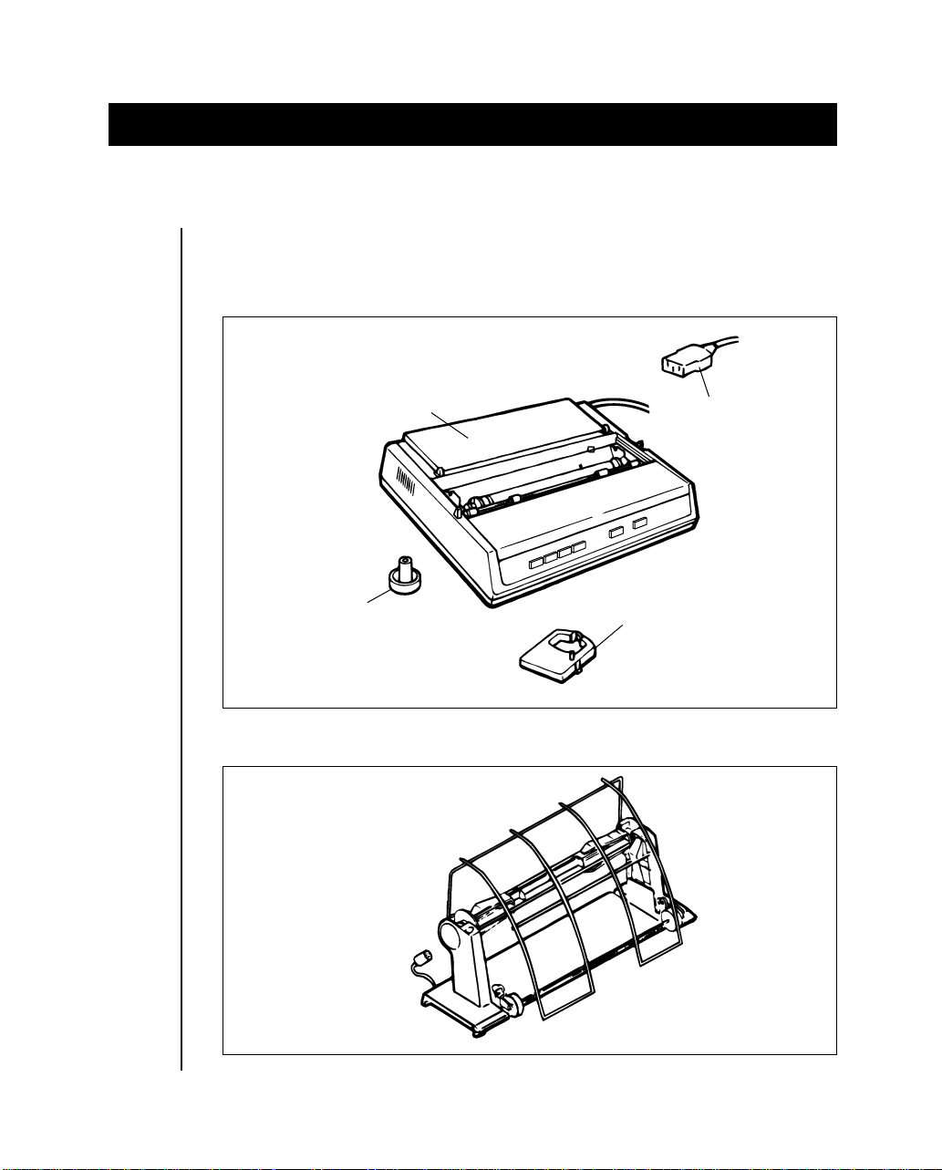
Your IBM/EPSON/OKI ML-compatible ML 184 Turbo+ printer is packed
in a protective container along with some extra items you need. These
items include:
Paper separator
Platen knob
Ribbon
cartridge
AC cable
Optional equipment available for your ML 184 Turbo+ printer includes:
Roll Paper stand
Setting Up 1 -- 1
Page 8
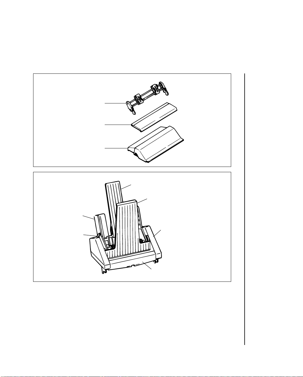
Tractor feed option kit
Tractor feed unit
Access cover
Acoustic cover
Cut-Sheet Feeder
Left paper guide
Paper test lever
Rear sheet support
Front sheet guide
Interface Equipment:
Super-Speed (19,200 baud) RS-232C serial board
1 -- 2 Setting Up
Front sheet support
Cut-Sheet Feeder unit
Page 9
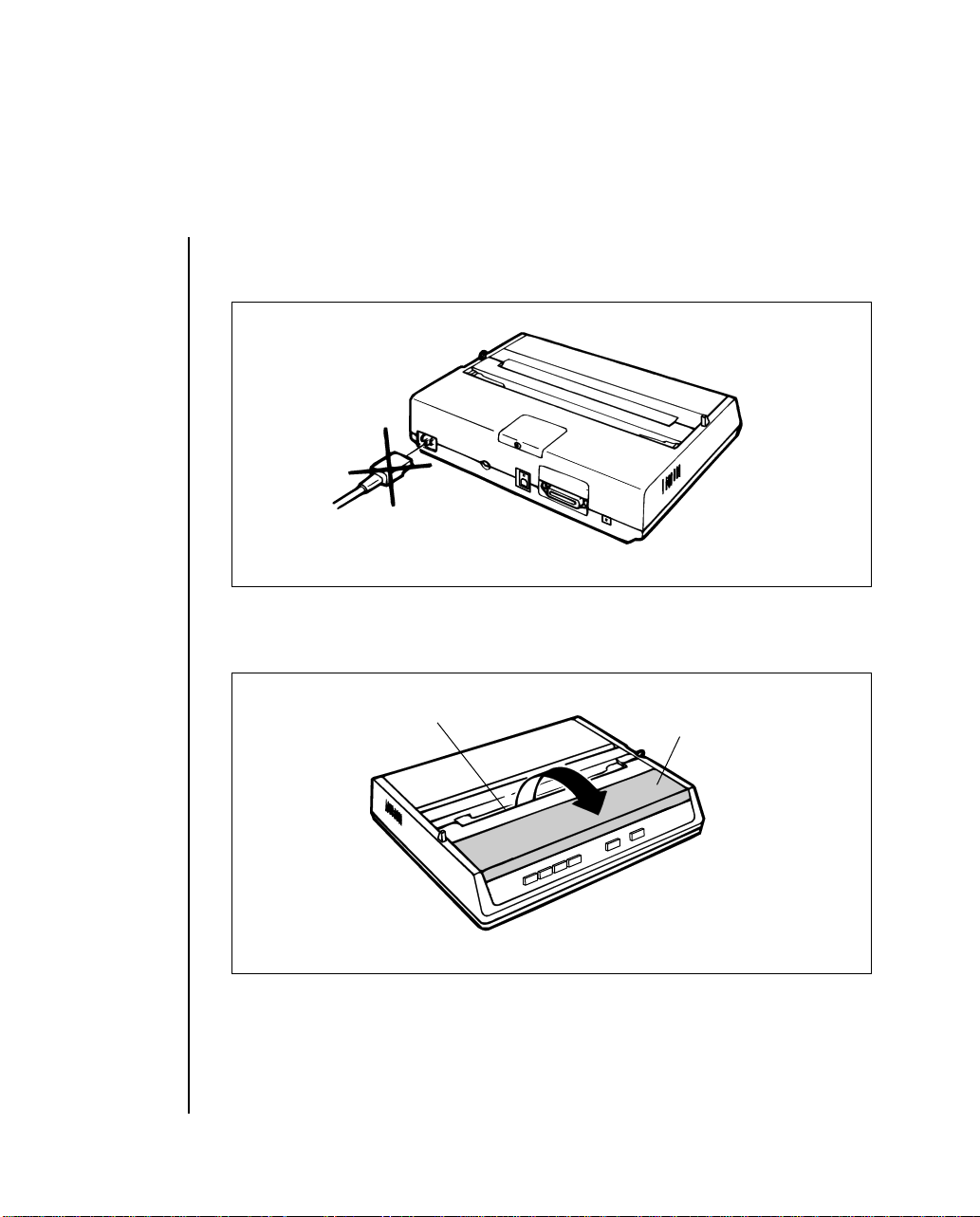
1. Do not plug in your printer until the following steps have been completed.
2. Remove the access cover by inserting your hand in the top cover slot
(see figure below) and lifting.
Slot
Access cover
Setting Up 1 -- 3
Page 10
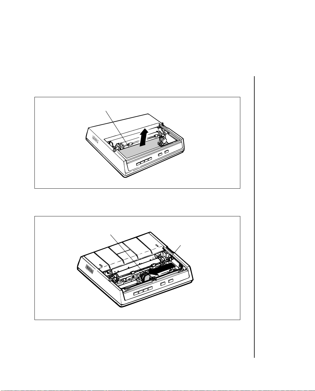
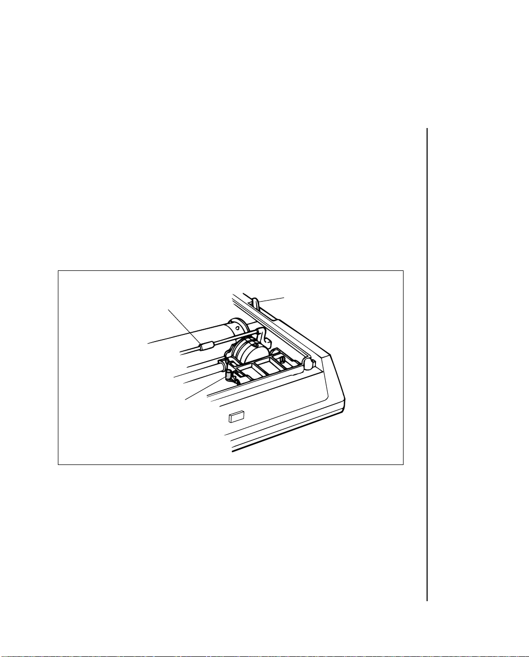
3. Remove the carriage shipping restraint that keeps the print head in
place.
Carriage shipping restraint
4. Gently slide the print head to the middle of the printer or to the lefthand
side so that it is away from the rollers on the Bail bar.
Print head
Bail bar
1 -- 4 Setting Up
Page 11
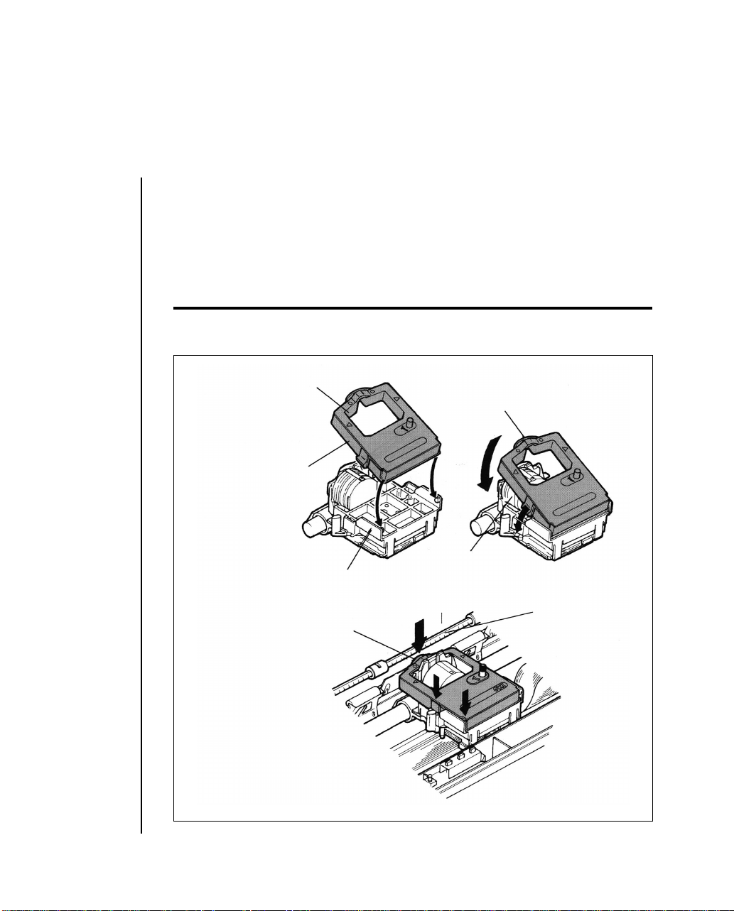
5. Place the black ribbon cartridge on the ribbon cartridge holder. The
easiest method is to tilt the back of the cartridge so that it slides into
the area of the plate that is nearest the front of the printer, then lower
the top of the cartridge (where the plastic ribbon shield is located)
over the print head. The tabs on both sides of the cartridge should
align perfectly with the inserts on the print head plate.
Important: Only use genuine OKI ribbon cartridges in your printer. Do not remove the
ribbon shield.
Ribbon cartridge
Ribbon shield
Holding position
Print head
Ribbon cartridge holder
Ribbon shield
Bail bar
Setting Up 1 -- 5
Page 12
6. Press gently on the cartridge until you feel it snap into place. To remove the ribbon cartridge, make sure the print head is moved away
from the edge of the platen, then grasp the cartridge on both sides of
the print head and lift up.
7. The blue lever located to the left of the ribbon cartridge is used to
adjust the print head gap for single or multi-part paper. When single
part paper or two part paper is in the printer, slide the blue lever forwards towards the print head. To print on three or four part paper,
slide the lever towards the front of the printer.
Bail bar
Print head gap lever
Print release lever
1 -- 6 Setting Up
Page 13
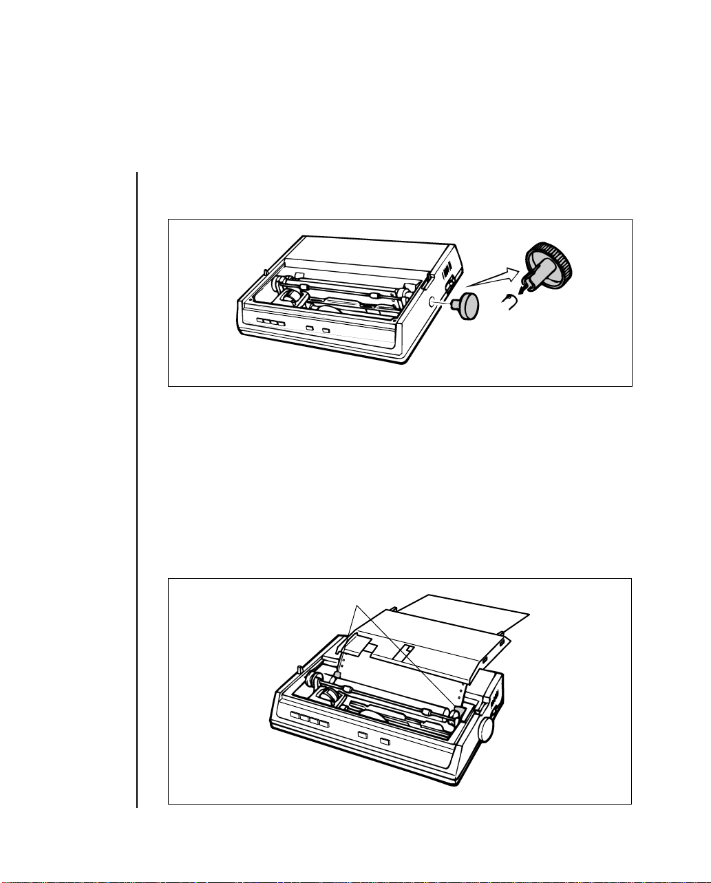
8. Put the platen knob shaft in the hole on the right-hand side of the
printer as shown.
9. Try running a self test to make sure your new printer is working correctly . Insert a piece of computer paper (with sprocket holes) or a single sheet of typing paper into the printer as you would insert it in a
typewriter. If you are unfamiliar with typewriters, here is the method:
a. Open the paper release lever by sliding it towards you.
b. After letting the slit of the paper separator pass, the paper as far
as you can into the slots provided by the black paper guides.
Paper guides
Setting Up 1 -- 7
Page 14

c. Close the paper release lever.
d. Turn the platen knob clockwise away from you to pull the paper
around the platen and behind the Bail bar.
e. Move the Bail bar back on to the platen so that the rollers rest on
the paper you have just inserted.
10. Advance the paper, using the platen knob, until 1 inch of paper appears above the Bail bar.
11. Replace the access cover:
a. Insert the three tabs in the edge of the access cover into the holes
on the top front edge of the printer.
b. Lower the access cover on to the printer.
12. Grasp the paper and pull it through the opening in the access cover.
Use the platen knob if you need more paper.
13. Insert the connector end of the power cord into the socket at the rear
of the printer.
14. Make absolutely certain that the ON/OFF power switch on the side of
the printer is OFF. (A sudden power surge can damage the printer.)
15. Plug the power cord into a earthed (three-pronged) electrical socket.
Important: The printer must be earthed at all times.
1 -- 8 Setting Up
Page 15
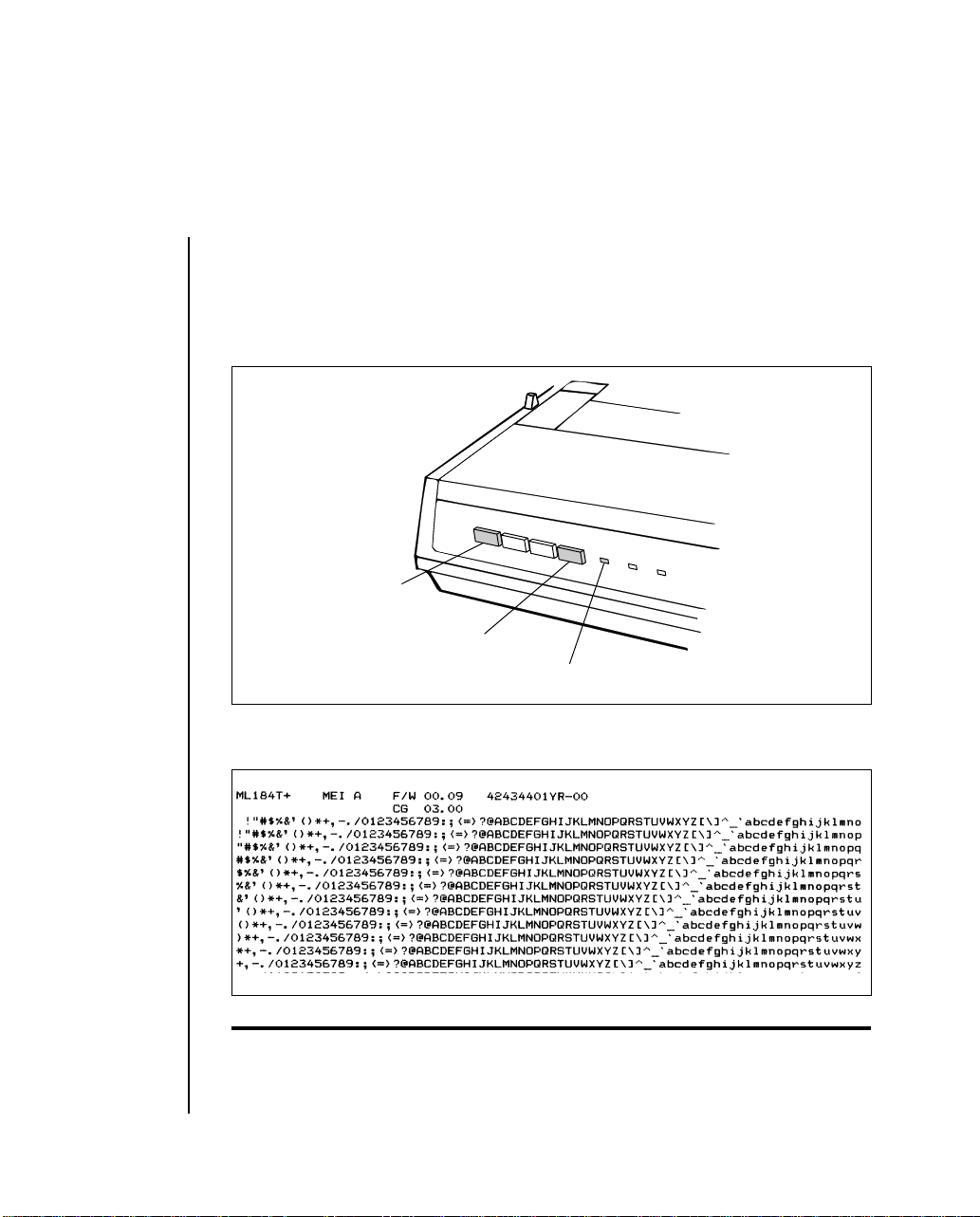
16. T o print the self test, hold down the LF (line feed) and SEL (SELECT)
button (located on the front panel) and turn the power switch ON.
When the printer is powered on (indicator lights), release the LF and
SEL button.
Line feed
SEL button
SELECT indicator
17. The following test pattern will be printed, beginning with a printer
revision number that is followed by a rolling character pattern.
Note: During self test printing the SELECT indicator is not lit.
Setting Up 1 -- 9
Page 16

18. To stop the test, press the SEL button (located on the front panel) or
turn the power switch OFF.
After the printer has shown that it is functioning correctly, you are ready
to connect your computer. First, you need an interface cable. If you do not
have one, see your computer dealer or, if you have the equipment and the
technical expertise, make your own cable using the instructions in Appendix C.
Attention: Install your printer away from a CRT. An electromagnetic field may create a
distortion on your computer screen.
1 -- 10 Setting Up
Page 17
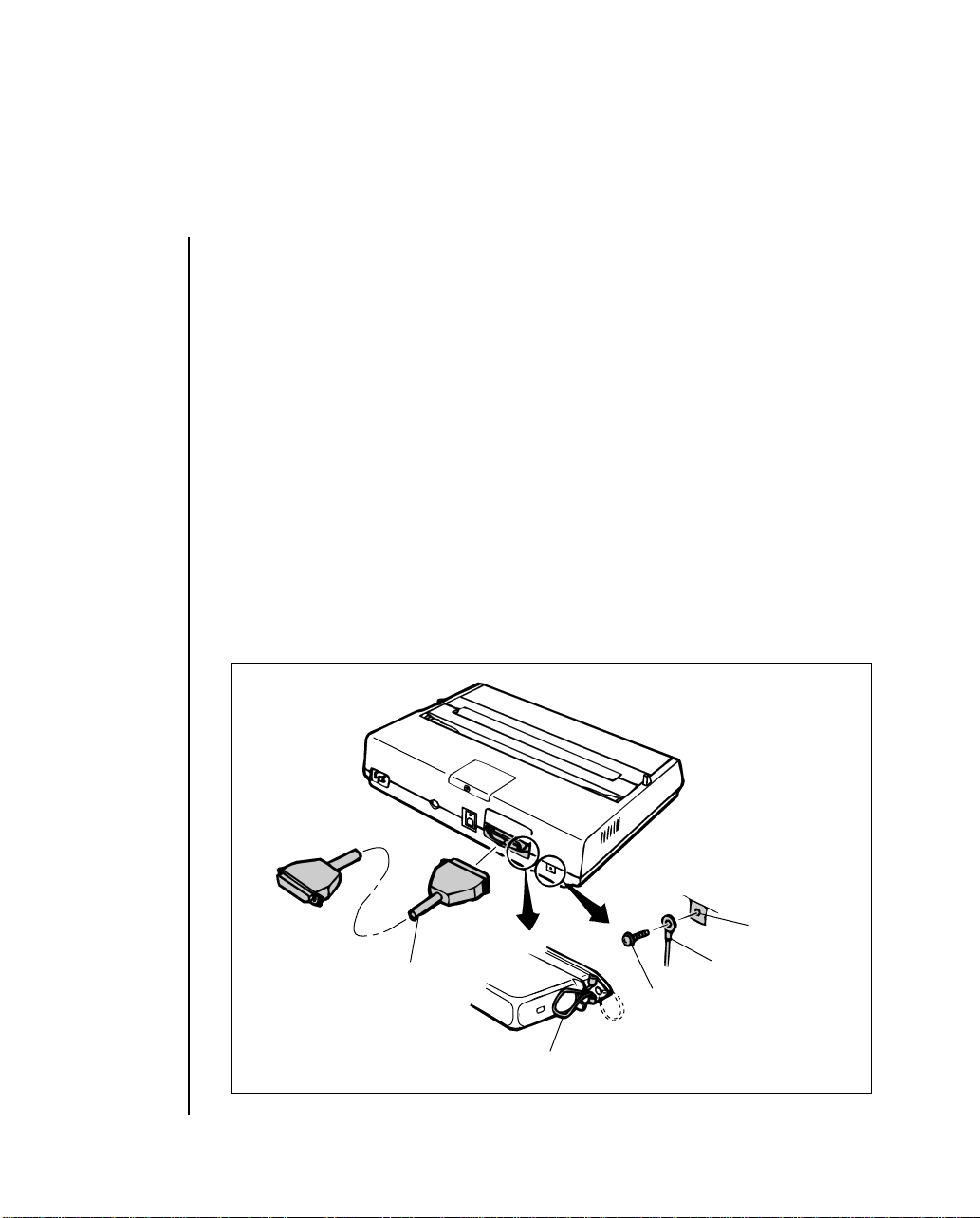
Connecting to Your Computer
Parallel interface cable
Locking tab
Frame
ground
screw
Frame
ground
wire
Frame
ground
Connector
hole
You will need either a parallel, usb or serial interface cable to connect
your computer to your ML 184 Turbo+ printer. Before you connect the
cable, make sure both printer and computer power is OFF.
* More than one interface cannot be connected simultaneously.
Connecting a Parallel Interface
1. Insert the 36-pin plug into the appropriate socket on the rear of the
printer.
If there is no frame ground (FG) included in your interface cable, connect a frame ground wire from the computer to the frame ground connection hole at the back of the printer.
Setting Up 1 -- 11
Page 18

2. Snap the two wire locking tabs on to the plug.
3. Insert the other end of the cable into your computer. You may also
connect it to another peripheral device, such as a disk drive, if your
equipment is designed for daisychain connection.
4. Turn on the equipment and try the one line BASIC program shown
below, using the proper print statement for your computer (the example uses LPRINT). Make sure you have paper and ribbon in the printer.
5. Type: LPRINT “Everything’s okay” and then run the program.
6. Y our printer should print “Everything’ s okay” at 10 characters per inch.
Note: If the printer did not print, make sure you entered the program correctly. Some computers require that you assign a number to the printer and specify that number in your print
statement; for example OPEN # 3 means the printer is on line # 3 to the computer.
7. Now try this BASIC program (change it, if necessary, to suit your
computer’s requirements):
10 LPRINT “EVERYTHING’S OKAY”
20 LPRINT “THIS LINE SHOULD BE SPACED 1/6“”;
CHR$(34);”UNDER THE FIRST”
8. The printout should look like this:
EVERYTHING’S OKAY
THIS LINE SHOULD BE SPACED 1/6” UNDER THE FIRST
1 -- 12 Setting Up
Page 19
If it is overprinted, make a small adjustment to the printer menu settings
so that a line feed is automatically inserted at the end of a line.
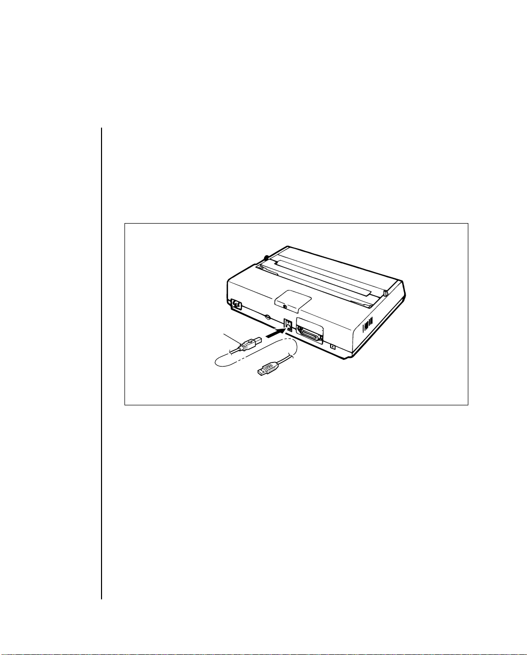
Connecting a USB Interface
1. Connect a USB cable to a USB port on the back of a printer.
USB cable
Serial Interfaces
The Super-Speed board has a maximum speed of 19,200 baud with a choice
of either printer Ready/Busy or XON/XOFF protocol.
Before connecting your interface cable, make sure both your printer and
computer are off. If you are using a serial cable, you are probably required
to use an OPEN and PR #1 statement in BASIC programming instead of
LPRINT. Consult your computer documentation for details.
Setting Up 1 -- 13
Page 20
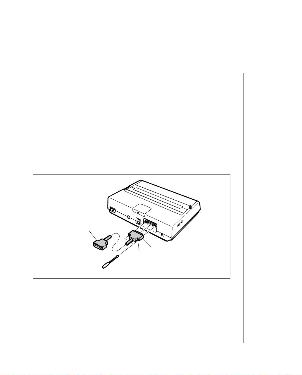
Connecting a Serial Interface
1. Insert the 25-pin plug in the socket on the rear of the printer.
2. Tighten the mounting screw on each side of the connector shell so that
it is securely attached to the printer.
3. Insert the other end of the cable into your computer. You may also be
able to connect the cable to another peripheral device, such as a disk
drive, if your equipment accommodates daisychain connection.
4. Make sure you have a ribbon cartridge and paper in the printer.
Serial interface cable
1 -- 14 Setting Up
Screw
25-pin plug
Page 21

5. Turn ON the power and try this one line BASIC program to make sure
the connection is correct:
LPRINT “Everything’s okay”
Note: Your computer may require a different print statement such as PRINT # 1 or PR #1.
Check your computer documentation for details.
6. Run the program. Your printer should print this at 10 characters per
inch:
Everything’s okay
7. Now try this BASIC program (modify it to suit your computer requirements):
10 LPRINT “Everything’s okay”
20 LPRINT “This line should be spaced 1/6”;
CHRS(34); “under the first”
8. The printout should look like this:
Everything’s okay
This line should be spaced 1/6” under the first
9. If the two lines of text have overprinted each other, you will have to
change the printer menu settings so that a line feed is automatically
inserted at the end of a line.
Setting Up 1 -- 15
Page 22

Page 23
Chapter 2
Operating Your Printer
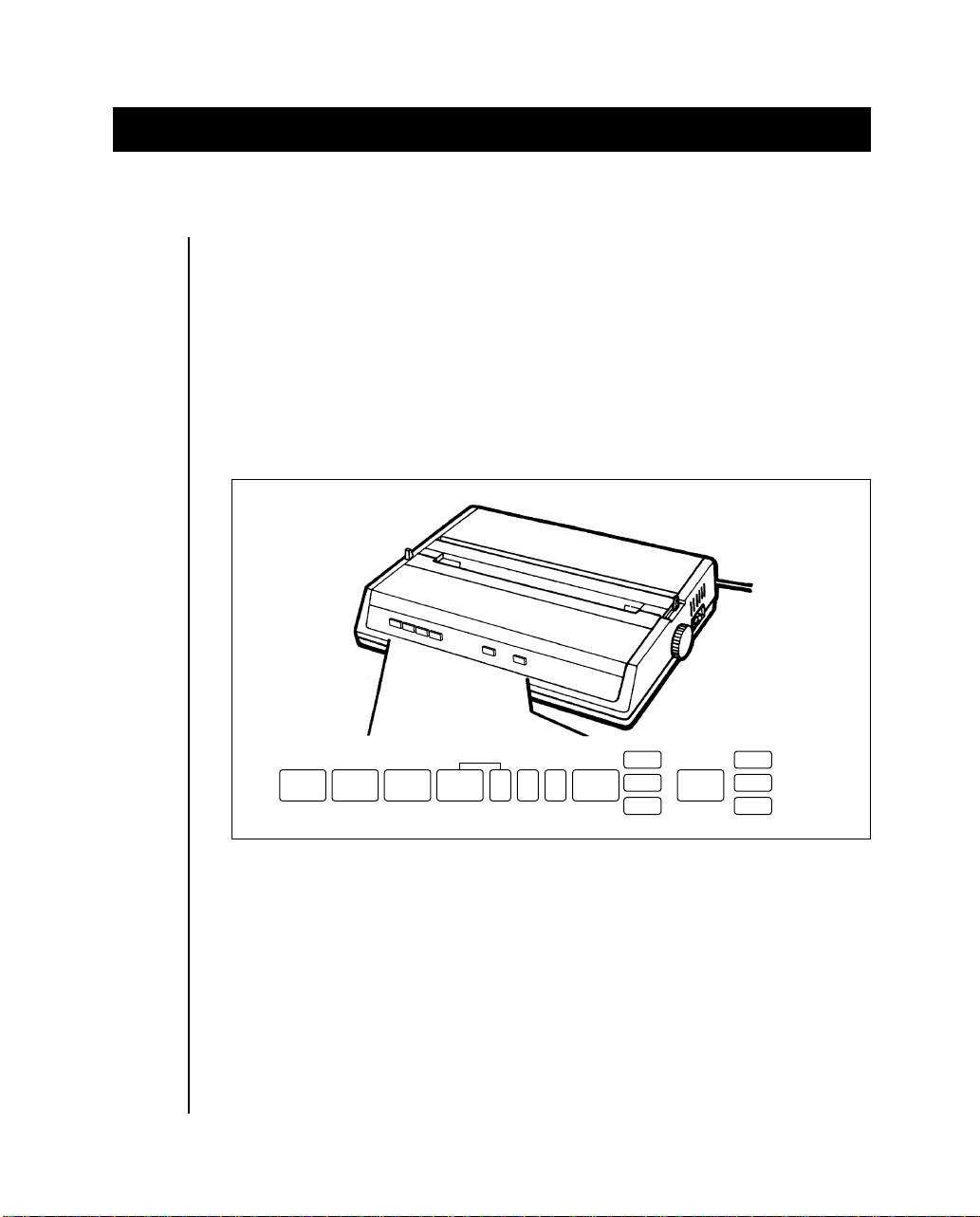
Buttons, Levers and Indicators
Before using your printer, it is worth familiarising yourself with the buttons, levers and indicators on the printer and to understand the various
methods of loading paper.
The front panel of the printer has six buttons, two of which were briefly
introduced in the setup procedure. In addition, there are indicator lights
that show the status of the printer, mode and pitch selected.
LINE
FEED
FORM
FEED
TOF
SELECT MODE
SET
ALARM PITCH
POWER 10
NLQ
12
17
UTILITY
HSD
POWER Indicator: Indicates that the printer power is turned ON.
SEL Button: Pressing this button after the printer power is ON
places the printer in deselect mode. In this mode
the computer cannot communicate with the printer .
T o return to select mode, simply press this button
again. Pressing this button also stops the self test.
It is also used to enter into HEX-dump mode: turn
the printer ON while holding down the SEL and
FORM FEED buttons.
Operating Your Printer 2 -- 1
Page 24
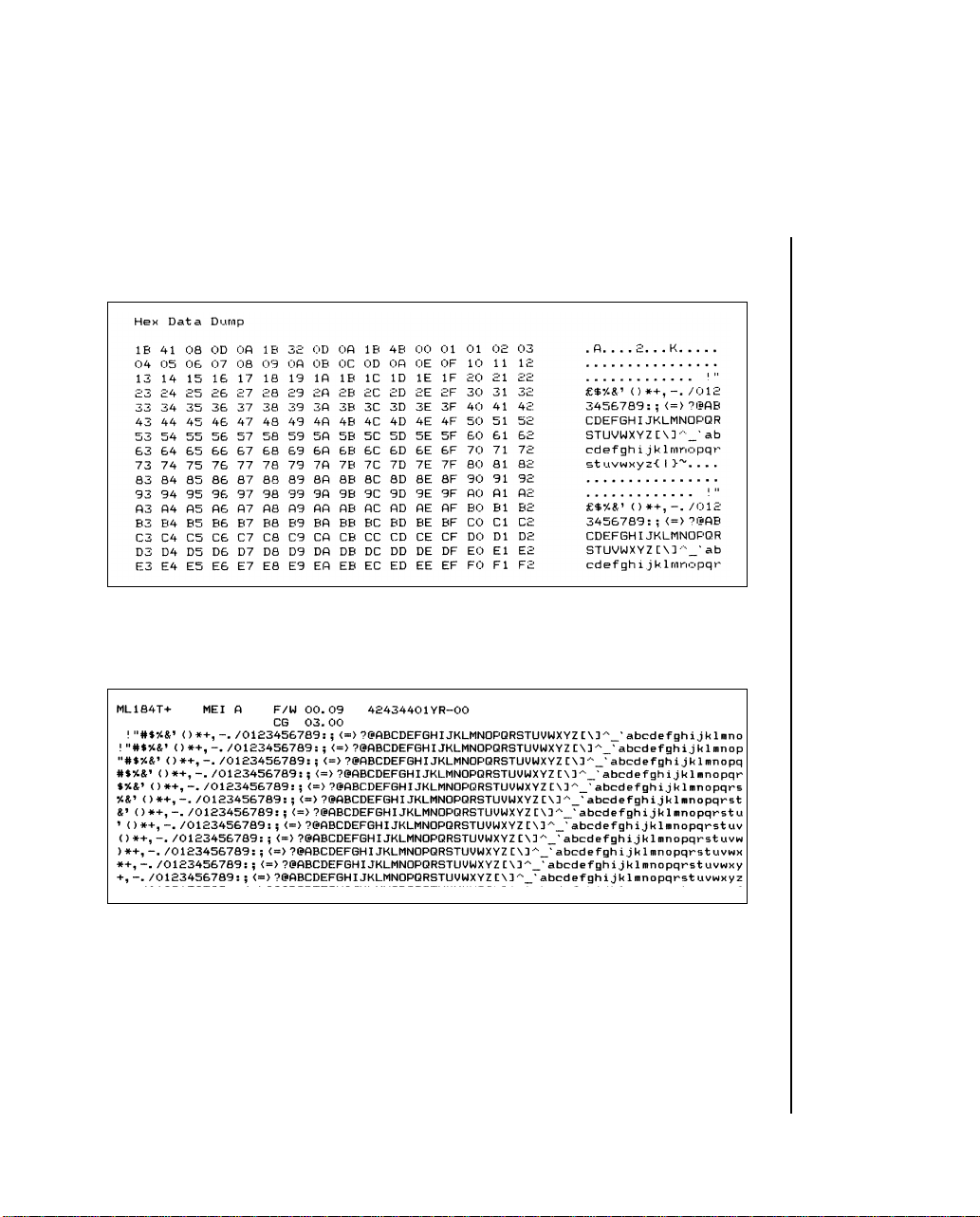
Hex mode generates data rather than text, and a sample is shown below . To
terminate this mode, switch the printer off and on again.
Switching on the printer while holding down the Select and Line Feed
buttons will generate a rolling ASCII character display. Reset the printer
to terminate. A sample is shown below.
TOF SET Button: To set the first line position on each page (Top of
Form), deselect the printer when the print head is
in the desired position. You can also select 17.1
character per inch printing by holding this button
down when turning printer power ON.
2 -- 2 Operating Your Printer
Page 25

SELECT Indicator: W orks together with the SEL button. Lights when
the printer is selected (ready to receive data from
the computer). The indicator is not lit when the
printer is deselected or during self tests. If an
abnormal status is detected during the self test,
the indicator flashes.
FORM FEED Button: To advance the paper to the next page (Top Of
Form), press this button while the printer is
deselected. You can also select NLQ (Near Letter Quality) with this button. Just hold down the
FORM FEED button while switching on the printer.
ALARM Indicator: Lights when paper supply is low or exhausted (un-
less you use the command to disable the alarm).
Printing stops until the paper supply is replenished. It is also lit when a jam is detected using
the CSF. The light flashes when high temperatures are detected in the printhead and space motor.
Allow the printer to cool down before re-using.
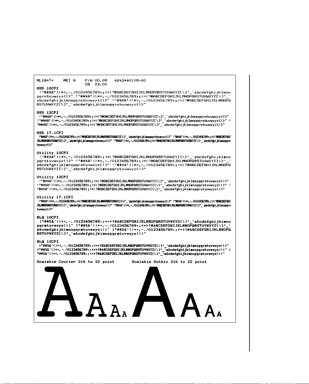
LINE FEED Button: If you want to advance the paper one line, press
this button while the printer is deselected. A DEMO
page print can be generated by switching on the
printer and holding down the Line Feed button.
This printout illustrates the various styles of printing
available from the ML 184 T urbo+. Once printed,
the printer automatically reverts to 10 cpi Utility
mode. An example of the DEMO page is on the
next page.
Operating Your Printer 2 -- 3
Page 26
2 -- 4 Operating Your Printer
Page 27

PITCH Button: This b utton allo ws you to manually select the char-
acter pitch. The appropriate lamp glows upon selection. The lamps also light as software changes,
for example, normal to condensed, are implemented.
MODE Button: Similar function to above, but this refers to the
print quality selected: NLQ, Utility or High Speed
Draft.
The levers on the printer allow you to adjust the paper.
PAPER LOCK/ Open (slide forwards) for inserting paper, and
RELEASE LEVER: adjusting paper, and when using tractor fed com-
puter paper. Close (slide back) for use with roll
paper and for single sheets.
PAPER GAP Slide towards the back of the printer when
ADJUSTMENT: inserting single sheets, and away when using
multipart paper.
Operating Your Printer 2 -- 5
Page 28

Menu Mode
When your printer is in the Menu Mode, you can use the front panel controls to change the defaults for the printer parameters, including emulation, page length, line spacing, typeface, pitch, etc. For example, you might
want to change the page length to 14 inches if you’re printing on legal-size
documents, or to 3 inches if you’re printing on labels or small cards.
T o place your printer in the Menu Mode, To place your printer in the Menu
Mode, turn on the power with pressing the SEL button.
To exit the Menu Mode, hold the PITCH button and press the MODE button. The MENU light will go out and the SEL light will come on.
2 -- 6 Operating Your Printer
Page 29
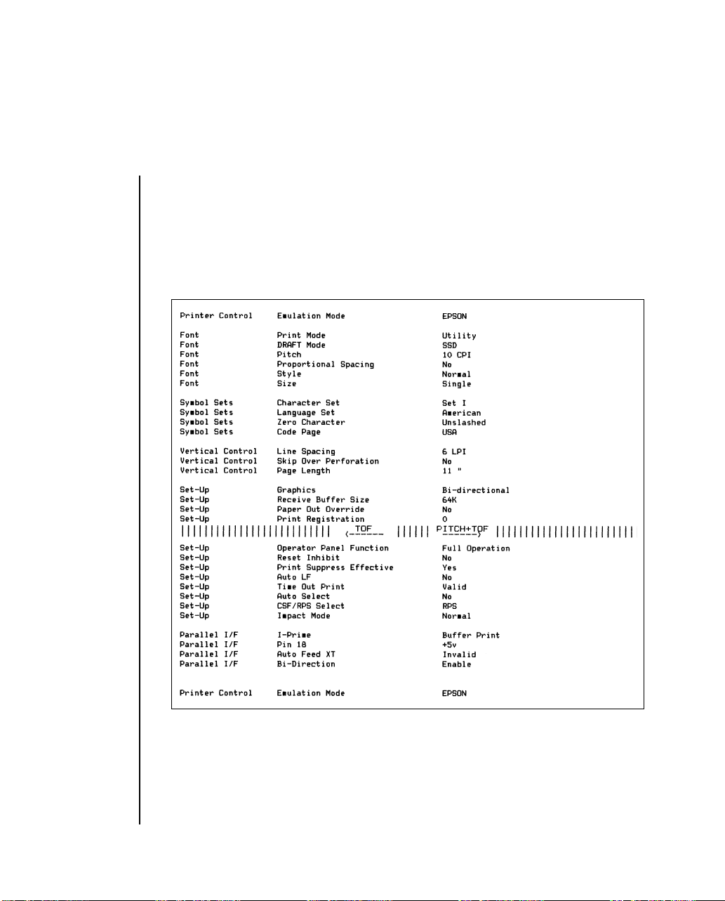
Sample Menu
The menu is made up of groups of parameters. Within each group is a list
of items and each of those items has several possible settings. Here’s a
sample Menu printout. The first column lists the groups; the second, items;
the third, settings:
Operating Your Printer 2 -- 7
Page 30
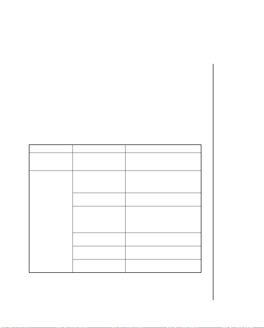
Summary of Menu Settings
The table below details the entries in the printer Menu as it comes from
the factory.
The factory defaults are marked with “*”.
Other entries will appear in the Menu depending on what options you have
installed and what emulation is engaged.
For a complete listing of all the available Menu selections, along with
explanations for each setting, see appendix D.
Group Item Sets
Printer Control Emulation Mode IBM *
Font Print Mode Utility *
DRAFT Mode HSD
Pitch 10CPI *
Proportional Spacing No *
Style Normal *
Size 1) Single *
2 -- 8 Operating Your Printer
Epson
ML
NLQ Courier
NLQ Gothic
DRAFT
SSD *
12 CPI
15 CPI
17.1 CPI
20 CPI
Yes
Italics
Double
Page 31

Group Item Sets
Symbol Sets Character Set Set I
*
Set II
Standard, Line Graphics, Block
Graphics (ML Mode only)
Language Set American *
Zero Character Slashed
Code Page USA * BRASCII
Slashed Letter O No *
Vertical Control Line Spacing 6 LPI *
Skip Over Perforation No *
French
German
British
Danish I
Swedish
Italian
Spanish I
Japanese
Norwegian
Danish II
Spanish II
Latin American
French Canadian
Dutch
Publisher
Unslashed *
Canada French Abicomp
Multilingual Multilingual 858
Portugal ISO8859-15
Norway
Yes
8 LPI
Yes
Operating Your Printer 2 -- 9
Page 32

Group Item Sets
Vertical Control Page Length 11"
11 2/3"
12" *
14"
17"
5"
3"
3.5"
4"
5.5"
6"
7"
8"
8.5"
Set-Up Graphics Bi-directional
Uni-directional *
7 or 8 Bits Graphics 4) 8
Receive Buffer Size 2) 1 Line
Paper Out Override No *
Print Registration 0.25 mm Right
7 or 8 Bits Data Word 4) 8 *, 7
Operator Panel Full Operation
Function 3) Semi Operation *
2 -- 10 Operating Your Printer
7 *
32K
64K *
128K
Yes
0.20 mm Right
0.15 mm Right
0.10 mm Right
0.05 mm Right
0 *
0.05 mm Left
0.10 mm Left
0.15 mm Left
0.20 mm Left
0.25 mm Left
Limited Operation
Page 33

Group Item Sets
Set-Up Reset Inhibit No *
Yes
Print Suppress Effective No
Auto LF No *
Auto CR 5) No
Print DEL Code 4) No
Yes *
Yes
Yes *
Yes *
Sl Select Pitch 15 CPI
(10 CPI) 5) 17.1 CPI *
Sl Select Pitch 12 CPI *
(12 CPI) 5) 20 CPI
Time Out Print Valid
Auto Select No *
ESC SI Pitch 5) 17.1 CPI *, 20CPI
CSF/RPS Select RPS *
Impact Mode Normal *
Invalid *
Yes
CSF
Quiet
Parallel I/F I-Prime Invalid
Buffer Print *
Buffer Clear
Pin 18 + 5V *
Open
Auto Feed XT 6) Valid
Invalid *
Bi-Direction Enable *
Disable
Operating Your Printer 2 -- 11
Page 34

Group Item Sets
CSF 7) Line Spacing 6 LPI *
Bottom Margin Valid
Page Length 11"
8 LPI
Invalid *
11 2/3"
12" *
14"
17"
5"
3.5"
4"
5.5"
6"
7"
8"
8.5"
Notes: 1. Selects both double width and double height characters OR single width and sin-
gle height characters.
2. When “1 Line” is selected, the receiving buffer size is set to 2K bytes.
3. When “Limited Operation” is selected, after exiting MENU, only the SEL, LF
and FF switches are valid. PRINT QUALITY, TOF and PITCH are invalid.
4. Displayed only for ML emulation.
5. Displayed only for IBM emulation.
6. Displayed only for EPSON emulation.
7. Displayed only when CFS is selected.
2 -- 12 Operating Your Printer
Page 35

Menu Mode Buttons
LINE
FEED
FORM
FEED
TOF
SET
SELECT MODE
ALARM PITCH
POWER 10
12
17
NLQ
UTILITY
HSD
Here is a summary of the buttons active in the Menu Mode:
1. LINE FEED button: Press to scan through groups of listings. Each
time you press the LINE FEED button, a line will print, showing the
next group in the Menu. T o go back one group, hold the PITCH button
while pressing the LINE FEED button.
2. FORM FEED button: Press to scan through items for a particular
group. Each time you press the FORM FEED button a line will print,
showing the next item within the group. To go back one item, hold the
PITCH button while pressing the FORM FEED button.
3. TOF SET button: Press to change setting for the items. Each time
you press the TOF SET button, a line will print across the page showing the next setting for that item. Keep pressing the button until the
setting you wish to engage appears. To go back one setting, hold the
PITCH button while pressing the TOF SET button.
4. SEL button: Press to print out listing of current settings for each items,
group by group.
Resetting Menu to Factory Defaults
T o reset your printer Menu to the factory settings, turn the printer of f, then
hold the LINE FEED and FORM FEED buttons while turning it back on
again.
Operating Your Printer 2 -- 13
Page 36

Paper Loading
You can load paper into the printer using several methods. If you have a
printer stand with a paper slot, you can load paper through the bottom of
the printer. If the printer is placed on a desk or table, paper can be loaded
from the top, like typewriter paper.
If you have the optional roll paper stand, tractor feed unit, or cut-sheet
feeder read the following instructions on how to install them and how to
load the paper.
When you use fanfold paper, adjust the distance between the sprocket pins
at the ends of the platen to correspond to the holes in the paper. You can
adjust the platen pin width by extending or compressing the platen ends.
To move the platen end: Unsnap the lever, move the platen end to the left
or right, then close the lever.
Bottom Feed Paper Loading
1. Place the printer on a slotted printer stand, carefully aligning the slot
in the stand with the opening in the base of the printer.
2. Place the box of paper under the printer stand.
3. Remove the access cover and lift the column indicator bar.
4. Open the paper release lever.
2 -- 14 Operating Your Printer
Page 37

5. Insert the first sheet of paper through the opening in the bottom of the
printer.
6. Slide the paper up until it appears in front of the platen.
7. Lower the column indicator bar.
8. Close the paper release lever.
9. Use the platen knob to advance the paper to the first printing line.
10. Replace the access cover.
Operating Your Printer 2 -- 15
Page 38

Rear Feed Paper Loading:
1. Put the printer on a desk or table.
2. Place the box of paper behind the printer.
3. Remove the access cover and lift the Bail bar.
4. Open the paper release lever.
5. Insert the first sheet of paper in the paper guide after letting a paper
pass to slit of the paper separator.
6. Push the paper in just enough so that its sprocket holes engage the
sprocket pins located on the platen ends.
7. Turn the platen knob to advance the paper until it appears in front of
the platen.
Paper guides
Bail bar
8. Lower the Bail bar.
9. Close the paper release lever.
2 -- 16 Operating Your Printer
Paper release lever
Page 39

11. Use the platen knob to advance the paper to the first printing line.
12. Replace the access cover.
Access cover
Operating Your Printer 2 -- 17
Page 40

Note: When the printed paper is involved in the platen, more the wire ahead.
Wire
If you adjust the printing position for the set paper by rotating the platen
knob in the reverse direction, the printing precision may fluctuate.
2 -- 18 Operating Your Printer
Page 41

Installing and Using the Roll Paper Stand
Select “RPS” at the “CSF/RPS Select” menu option.
1. Remove the access cover.
2. Insert the tabs on the roll paper stand into the holes on both sides of
the printer.
Roll Paper
Stand
3. Plug the roll paper stand plug into the socket on the rear of the printer .
Plug
Operating Your Printer 2 -- 19
Page 42

4. Pull the bail arm lever forwards to move the column indicator away
from the platen.
5. Place the paper release lever in the forward (open) position.
6. Insert the paper shaft in the roll paper core, and open the sheet guide
of the roll paper stand. Mount the shaft on the stands so that the grooved
end of the shaft fits into the groove on the left stand, and the paper
rolls from the bottom.
Paper shaft
Sheet guide
Bail arm lever
Roll Paper
Release lever
7. Insert the paper from the back of the platen over the paper bar, making
sure its edges lie within the platen ends. (The sprocket pins will tear
the paper if they come into contact with it.)
8. Push the paper in slightly. Close the paper release lever. Now turn the
platen knob to bring the paper to the front of the platen.
2 -- 20 Operating Your Printer
Page 43

9. Feed the paper supplied to the front of the platen in Step 8 through the
slit between the indicator and the platen. If necessary, align the edges
of the paper. You must open the paper release lever to do this.
10. Close the bail arm lever.
Align the ends
Bail arm lever
Sheet guide
Release lever
11. Replace the access cover. Fit the cover tabs into the slots at the printer
front. Lower the cover carefully , making sure the paper feeds through
the front slot in the access cover.
12. By turning the platen knob, move the paper to the point where you
want printing to start. (Many word processing packages automatically
allow for a top margin of 25.4 mm (1 inch).
Sheet guide
Operating Your Printer 2 -- 21
Page 44

Loading Single Sheets
The ML184 Turbo+ can accommodate standard single sheets of 216 by
297 or 355 mm (8.5 by 11-inch or 14-inch) paper. Only one copy, with no
carbons, can be printed at a time.
Remove the tractor feed unit and any other accessories before using the
paper separator.
Operation
1. Place the paper release lever in its rear (closed) position.
2. Place the printer OFF LINE. (Press the SEL switch.)
3. Close the paper bail lever (Place it in its rearward position.)
4. Raise the paper separator as shown in the figure. (The paper separator
remains raised to prevent the paper separator from falling.)
5. Adjust the cut sheet guide on the paper separator to the printing pattern to be used.
Cut sheet guide
Paper bail lever
2 -- 22 Operating Your Printer
Single sheet
Paper separator
Stay
Page 45

Line mark
Cut sheet guide
Note: When letter-size paper is used, set the cut sheet guide to the line mark on the paper
separator then 80-characters (10 CPI) width can be printed in the centre position of the paper.
6. Insert a single sheet along the cut sheet guide until it reaches the pinch
roller . Be sure to keep the paper inside the platen ends. Otherwise the
built-in sprocket pins will tear it.
7. Open the paper bail lever, place it in its forward position.
8. Close the paper bail lever after confirming that the single sheet has
been grasped. Be sure to throw the paper bail lever all the way; otherwise the paper will jam.
9. Press the SEL key after confirming that the paper is fed again up to
the first-line printing position. Then place the printer ON LINE.
Attention: Load paper properly in order for paper to be fed straight.
Operating Your Printer 2 -- 23
Page 46

Installing and Using the Tractor Feed Unit
1. Remove the access cover.
2. Insert the post on each end of the tractor feed unit around the ends of
the platen shaft.
Post
Tractor feed unit
Lever
Clamp
Side frame
3. Pull the tractor unit forwards until it clamps on to the platen ends.
4. Install the paper separator by placing its hooks in the slots provided
on the printer.
2 -- 24 Operating Your Printer
Page 47

5. Paper can be loaded from the top or bottom of the printer. Paper can
only be loaded from the bottom if you have a slotted printer stand.
Rear feed
Bottom feed
Operating Your Printer 2 -- 25
Page 48

6. Adjust the left tractor if necessary; make sure it is not more than 12.7
mm (1/2 inch) from the left-hand end of the tractor unit. To move the
tractor pull the lock lever forwards, slide the tractor to the desired
position, then push it backwards to lock it in place.
Lock lever
Sprocket cover
Tractor
7. Pull the paper under the column indicator and up to the level of the
tractor unit.
8. Adjust the right tractor to the paper width by pulling the lock lever
forwards, sliding the tractor to the right or left (depending on the paper size), and pushing the lock lever backwards to lock it in place.
2 -- 26 Operating Your Printer
Page 49

9. Open the sprocket covers and the paper release lever (slide forwards).
Tractors
Sprocket covers
10. Place the sprocket holes in the paper over the sprockets on the tractor
unit, making sure that the paper is flat.
Sprocket pins
Sprocket holes
Operating Your Printer 2 -- 27
Page 50

11. Close both the sprocket covers. (Leave the paper release lever open.)
Sprocket covers
12. Put the access cover supplied with the tractor feed unit on the printer.
Access cover
2 -- 28 Operating Your Printer
Page 51

Installation of the Cut-Sheet Feeder
Select “CSF” at the “CSF/RPS Select” menu option.
1. Remove the acoustic cover, tractor feed unit, and paper separator if
installed.
2. Remove the access cover.
3. Pull the column indicator away from the platen and push the pressure
rollers to the left and the right end of the bar.
4. Fit the cut-sheet feeder clamps over the platen collar and lower on to
the printer.
Notes: 1. Move the front sheet guide of the cut-sheet feeder under the column indicator.
Gently push the front sheet guide towards the platen, then close the column indicator. To engage it with the front sheet guide hook, pull it back to open position.
2. Turn the platen knob to make sure the coupling gear on the left-hand side of the
cut-sheet feeder are in line with the platen gear.
Clamp
Coupling gear
Platen gear
Platen collar
5mm
Pressure roller
Column indicator bar
Front sheet guide
Platen collar
Pressure roller
5. Insert the sheet supports. Fit the slotted ends of the narrow sheet support on to the square bar and paper chute on to either side of the middle paper guide at the rear of the cut sheet feeder. Slide the front sheet
support into the tracks between the feed rollers and the metal plate.
Operating Your Printer 2 -- 29
Page 52

6. Insert the feeder cable into the socket on the rear of the printer. The
arrow on the plug faces up.
Feed cable
Paper release lever
(Closed)
7. Make sure the printer’s paper release is closed.
Important: Be sure the paper release lever is closed whenever you are printing with the cutsheet feeder. If you do not close the paper release, the paper will not feed properly. The
printer could print an entire page without any paper, possibly damaging the platen and the
print head.
Loading paper into the hopper
1. Put the paper set level to the RESET position.
(a)
2 -- 30 Operating Your Printer
Paper set lever
(b)
Right paper guide
Paper guide fixing levers
Left paper guide
Page 53

2. Release the paper guides by pushing the fixing levers downwards.
3. Move the left paper guide to the position where you wish to set the
left-hand edge of the sheet. Make sure that this guide is not set to the
right of the paper out sensor (the groove in the platen).
Left paper guide
4. Flex the paper stack (not more than 170 sheets of 60g/m
12
Right paper guide
2
(161b) paper). Square the stack again, turn it over, and repeat the bending. The
paper stack should not exceed 16mm in total thickness.
Operating Your Printer 2 -- 31
Page 54

5. Insert the paper stack in the hopper, then push it against the left paper
guide. Make sure the paper fits under the corner separators. Adjust the
right paper guide to the width of the paper.
Paper stack
Left paper guide
Paper set lever
Right paper guide
6. Push the paper guide fixing levers upwards into the locked position.
Tuck the paper
stack under the
rollers
Roller
2 -- 32 Operating Your Printer
Stopper
Page 55

Rear sheet supporter
0.5~1mm
Right-hand
paper guide
7. Push the paper set lever gently backwards to the set position.
Paper set lever
Operating Your Printer 2 -- 33
Page 56

Manual paper loading with the cut-sheet feeder installed.
1. Gently insert the paper from directly above the front sheet support.
Front sheet
supporter
Slot for setting
manually
FORM FEED button
2. Use the FORM FEED button to feed the manually loaded paper.
3. Turn the platen knob clockwise/anticlockwise until the sheet is in the
desired position.
Notes: 1. The manually set sheet is printed automatically even when other sheets are
loaded in the hopper. (When the FORM FEED button is pressed, the manually
set sheet will be fed into the cut-sheet feeder.)
2. Do not manually feed paper if a sheet is being fed from the hopper. Simultaneously feeding paper may result in a paper jam.
3. To manually feed a sheet of paper, you must use the FORM FEED button, and
use the platen knob to adjust the papers position in the printer. If the paper is being
fed manually and is positioned using the platen knob rather than the FORM FEED
button it may be ejected just before printing begins.
2 -- 34 Operating Your Printer
Page 57

Cut-sheet feeder controls
The printer’s control switches also control the operation of the cut-sheet
feeder. The control switches, however, function only when the printer is
off-line or deselected (SELECT indicator is not lit).
Printing with the cut-sheet feeder
After the first sheet is inserted and the top of form is set, you can begin
printing with the cut-sheet feeder. Simply request a printout from your
word processing package as normal. When it receives the PRINT command, the printer starts printing on the inserted sheet until the amount of
lines that have been printed according to the appropriate page length, ejects
the printed page into the output tray, and inserts a new page. If a file is
several pages long, the printer ejects each printed page into the output
tray, inserts a new sheet from the hopper, then continues printing.
If you are printing program outputs using the cut sheet feeder, you must
include the cut-sheet feeder insert and eject commands. When the printer
receives the PRINT command, it inserts a sheet of paper and starts printing. Each time the printer receives the cut-sheet feeder insert command, it
ejects the printed sheet then inserts a new sheet. Use the cutsheet feeder
eject command at the end of your program if you want the printer to eject
the printed sheet without inserting a new sheet. For further information
consult the programming section in this handbook.
If you want to eject a sheet of paper you can do it using the FORM FEED
button.
Note: Make sure that the page length the printer is set to is no greater than the page length
that your word processing system uses.
The action of the LINE FEED button varies according to the status of the
cut sheet feeder.
Operating Your Printer 2 -- 35
Page 58

Page 59

Chapter 3
Working with Software
This chapter covers the fundamentals of setting up commercial software
packages for use with your printer. Be sure to read your software documentation
carefully for more details.
Basic Terminology
Before we start, let’s examine a few terms with which you may not be
familiar.
Printer Commands
If you’re using commercial software with an appropriate printer
driver (see “Printer Drivers” below), the printer commands will
normally be sent to the printer by your software and you won’t
even need to think about them.
Printer commands are signals sent by your PC to the printer which guide
and control its operation. Printer commands tell the printer what character
pitch to use, what font to use, what margins to use, whether to use single
or double spacing, when to engage/disengage double width or double height
printing, etc.
Printer commands can be sent in decimal, ASCII, or hexadecimal form.
The values (decimal/ASCII/hexadecimal) for each type of command depend
on which emulation is active (see Appendix A for a listing of printer commands
for each emulation).
With only a few exceptions, printer commands begin with the ESC character ,
decimal 27 (hexadecimal 1B), which serves as signal to the printer that
what follows is to be interpreted as a command rather than just a string of
characters. Some printer commands expect you supply a numerical value,
representing tab stops, line spacing, etc.
Working with Software 3 -- 1
Page 60

Emulations
In order to eliminate hundreds of different sets of printer commands, most
printers emulate, or imitate, one of several general printers; i.e., they accept
all of that printer’s commands and behave as though they were the emulated
printer.
Your printer has three emulations:
• IBM (factory default)
• Epson
• Oki Microline
Printer Drivers
Compatible Printer Drivers (DOS)
Many of the software packages you use will contain drivers 100% compatible
with your printer. For older software, however , it may be necessary to select
a driver that functions nearly the same as a driver specifically designed for
your printer. This generally means that you will be selecting a driver that
provides commands to access most, but not all of the available functions;
however, the commands that are available will perform properly with your
printer.
The table below summarizes the various drivers that will work with your
printer . They are listed in order by decreasing compatibility as you go down
the list: select one from as high up on the list as possible, based on what is
available from among the drivers supplied with your software. If you don’t
see one from near the top of the list, give the software manufacturer a call
to see if they have added any drivers to those supplied when you purchased
your software. Software manufacturers are constantly updating their lists
of drivers to keep up with the printer market and they may very well have
one which will give maximum compatibility with your printer.
3 -- 2 Working with Software
Page 61

IBM Emulation Epson Emulation
OKI ML Emulation
Oki ML 184 Turbo (IBM)
Oki ML 320 (IBM)
Oki ML 520 (IBM)
Oki ML 320 T (IBM)
Oki ML 720 (IBM)
IBM Graphics printer
IBM Proprinter
Oki ML 320 (EPSON)
Oki ML 520 (EPSON)
Oki ML 320 T (EPSON)
Oki ML 720 (EPSON)
Epson EX 800
Epson FX
Oki ML 184 Turbo (STD)
Oki ML 182 (STD)
Oki ML 192 (STD)
Oki ML 320 (STD)
Oki ML 520 (STD)
Oki ML 320 T (STD)
Oki ML 720 (STD)
Because there are some differences in characteristics such as speed or access
to various features, you may wish to experiment with several different
drivers. If you must select a driver that is not listed in the table, be sure to
check it thoroughly for print features such as boldface, underline and changes
in pitch. Don’t be surprised if boldfaced items are printed twice, underlines
are misplaced, wide spaces are left between lines or the printer behaves
chaotically (turn off the printer if the latter occurs). These are all characteristics
of an incompatible driver selection.
Windows Printer Drivers
To use this printer on a Windows operating system, install the Windows
printer driver, that is on the Printer Software CD-ROM provided with your
printer, on your computer.
For information about which Windows systems are compatible with the
printer drivers on the Printer Software CD-ROM and the installation procedure
open the Readme file on the Printer Software CD-ROM.
Working with Software 3 -- 3
Page 62

Page 63

Appendix A
Printer Commands
This appendix contains a listing of the printer commands for the IBM,
Epson, and OKI MICROLINE emulations, grouped by function.
IBM Printer Commands
IBM Function ASCII Code
Bar Code Commands
Select Bar Code Type
and Size
Print Bar Code Data
Print Postnet Bar Code
Select Bar Code Type
Print Bar Code
Character Sets
Select IBM Character Set I
Select IBM Character Set
Print from IBM
Character Set III
Print One Character from
IBM Character Set III
Select International
Character Set *
Select Code Page
Character Size/Spacing
Select 10 cpi Pitch
Select 12 cpi Pitch
Select 15 cpi Pitch *
Select 20 cpi Pitch *
Set Compressed Pitch
Superscript Printing On
Subscript Printing On
Super script/Subscript
ESC DLE A m n
ESC DLE B m n [data]
ESC DLE C n [data]
Data
ESC [ f L
L
v Hv Pc
ESC [ f Ln Hn DATA
ESC 7
ESC 6
II
ESC \ L
ESC n
ESC ! n
ESC [ TL
0
DC2
ESC :
ESC g
ESC SI
SI
ESC S 1
ESC S 0
ESC T
n
1
n Hn Pk Pm Ps
n Hn
0 0 Hcp Lcp
n Hn
Decimal Code
27 16 65 m n1 n
8
27 16 66 m n [data]
27 16 67 n [data]
27 91 102 L
P
m Ps Lv Hv Pc
27 91 112 Ln Hn
DATA
27 55
27 54
27 92 L
27 94 n
27 33 n
27 91 84 L
H
cp Lcp
18
27 58
27 103
27 15
15
27 83 1
27 83 0
27 84
n Hn
0
n Hn Pk
n Hn
Hexadecimal Code
1B 10 41 m n1 n
8
1B 10 42 m n [data]
1B 10 43 n [data]
1B 5B 66 L
P
m Ps Lv Hv Pc
1B 5B 70 Ln Hn
DATA
1B 37
1B 36
1B 5C L
1B 5E n
1B 21 n
0 0
1B 5B 54 L
H
cp Lcp
12
1B 3A
1B 67
1B 0F
0F
1B 53 01
1B 53 00
1B 54
n Hn
0
n Hn Pk
0 0
n Hn
8
Appendix A: Printer Commands A -- 1
Page 64

IBM Function ASCII Code
Character Size/Spacing
(cont.)
Start Double Width
SO
Printing Line by Line
End Double Width
DC4
Printing Line by Line
Double Width Printing
ESC W 1
On
Double Width Printing
ESC W 0
Off
Double Width and/or
ESC [ @ L
Height Printing On
Proportional Spacing On
Proportional Spacing Off
Set Intercharacter
ESC P1
ESC P0
ESC Vn
Spacing *
Character Style
HSD Print Mode On
Select Font
Italics On
Italics Off
Emphasized Printing On
Emphasized Printing Off
Enhanced Printing On
Enhanced Printing Off
Underline On
Underline Off
Overscore On
Overscore Off
Select font by Pitch and
ESC # 0
ESC I n
ESC % G
ESC % H
ESC E
ESC F
ESC G
ESC H
ESC - 1
ESC - 0
ESC 1
ESC 0
ESC DEL F P
Point
ESC [ I Ln Hn Hfid Lfid
Select Font
Select Print Quality
Hfwd Lfwd fa Nul H
ESC [ d Ln Hn P
Custom Characters
Down Line Load
Characters
Copy ROM Character Set
ESC = c1 c2 m n a1 a2 d1
d
k
ESC $
to RAM Character Set *
n Hn m1
n0 Pn Lp Hp
n
m
Decimal Code
14
20
27 87 1
27 87 0
27 91 64 L
k
m
k
27 80 1
27 80 0
27 86 n
27 35 48
27 73 n
27 37 71
27 37 72
27 69
27 70
27 71
27 72
27 45 1
27 45 0
27 95 1
27 95 0
27 16 70 P
H
p
27 91 73 Ln Hn Hfid
Lfid Hfwd Lfwd fa
c Lc
Nul H
c Lc
27 91 100 Ln Hn P
27 61c1 c2 m n a1 a2
d
d
1
k
27 36
n Hn m1
n0 Pn Lp
Hexadecimal Code
0E
14
1B 57 1
1B 57 00
1B 5B 40 L
m
1B 50 01
n Hn m1
k
1B 50 00
1B 56 n
1B 23 30
1B 49 n
1B 25 47
1B 25 48
1B 45
1B 46
1B 47
1B 48
1B 2D 01
1B 2D 00
1B 5F 01
1B 5F 00
1B 10 46 P
H
1B 5B 49 Ln Hn Hfid
n0 Pn Lp
p
Lfid Hfwd Lfwd fa
Nul H
c Lc
1B 5B 64 Ln Hn P
n
1B 3D c1 c2 m n a1 a2
d
d
1
k
1B 24
n
Cut-Sheet Feeder Control
Insert/Eject Paper *
ESC EM n
A -- 2 Appendix A: Printer Commands
27 25 n
1B 19 n
Page 65

IBM Function ASCII Code
Graphics
Single Density Graphics
Double Density Graphics
Double Speed/Double
ESC K L
ESC L L
ESC Y L
Density Graphics
Quadruple Density
ESC Z L
Graphics
Horizontal Control
Backspace
Carriage Return
Margin Setting, Left &
BS
CR
ESC X n m
Right
Horizontal Tab
Set Horizontal Tab
Clear Horizontal Tab
HT
ESC D n
ESC D 0 0
Settings
Set 4-column Tabulation *
Set Print Position *
Set Relative Dot Position *
Uni-directional Print On
Uni-directional Print Off
Set Relative Print Position
ESC % B n
ESC DLE @ Pn A1 A2 P1
P
2 P3 P4
ESC | Ln H
ESC U 1
ESC U 0
ESC d L
Vertical Control
Page Length, Set in n
ESC C 0 n
Inches
Page Length, Set in Lines
Skip Over Perforation On
Skip Over Perforation Off
Set Top of Form at
ESC C n
ESC N n
ESC O
ESC 4
Current Position
Form Feed
Line Feed
n
Perform
Perform
Auto Line Feed On
/
216
n
/
144
" Line Feed
" Line Feed
Auto Line Feed Off
Set Line Spacing to
Set Line Spacing to
7
1
/72"
/8"
FF
LF
ESC J n
ESC % 5 n
ESC 5 1
ESC 5 0
ESC 1
ESC 0
n Hn
n Hn
n Hn
n Hn
nk 0
1 n2
1 n2 n3 n4
n
n Hn
[data]
[data]
[data]
[data]
Decimal Code
27 75 Ln Hn [data]
n Hn
n Hn
n Hn
[data]
[data]
[data]
27 76 L
27 89 L
27 90 L
8
13
27 88 n m
9
27 68 n
1 n2
nk 0
27 68 0 0
27 37 66 n
1 n2 n3 n4
27 16 64 Pn A1 A2
P
1 P2 P3 P4
27 124 Ln H
n
27 85 1
27 85 0
27 100 L
n Hn
27 67 0 n
27 67 n
27 78 n
27 79
27 52
12
10
27 74 n
27 37 53 n
27 53 1
27 53 0
27 49
27 48
Hexadecimal Code
1B 4B Ln Hn [data]
n Hn
n Hn
n Hn
[data]
[data]
[data]
1B 4C L
1B 59 L
1B 5A L
08
0D
1B 58 n m
09
1B 44 n
1 n2
nk 0
1B 44 0 0
1B 25 42 n
1 n2 n3 n4
1B 10 40 Pn A1 A2 P1
P
2 P3 P4
1B 7C Ln H
n
1B 55 1
1B 55 00
1B 64 L
n Hn
1B 43 00 n
1B 43 n
1B 4E n
1B 4F
1B 34
0C
0A
1B 4A n
1B 25 35 n
1B 35 01
1B 35 00
1B 31
1B 30
Appendix A: Printer Commands A -- 3
Page 66

IBM Function ASCII Code
Vertical Control (cont.)
Set Line Spacing to n/
Set Line Spacing to 7/
Set Line Spacing to n/72"
Line feed compound
command
Perform Line Feed Set by
"
ESC 3 n
216
" *
ESC % 9 n
144
ESC A n
ESC DLE H Pno A1 A2
P1 P2 P3
ESC 2
ESC A n Command
Vertical Tab
Set Vertical Tab
Reset Vertical Tab to
VT
ESC B n1 n2 nk 0
ESC R
Defaults
Miscellaneous
Cancel
Change Emulation *
Paper-Out Sensor On
Paper-Out Sensor Off
Print Suppress Mode On
Print Suppress Mode Off
CAN
ESC { n
ESC 8
ESC 9
ESC Q STX
DC1
(either Model)
Set Initial Conditions
Software I-Prime *
Stop Printing
ESC [ K Ln Hn Init Id a1 a
ESC } 0
ESC j
* OKI-Unique command
Decimal Code
27 51 n
27 35 57 n
27 65 n
27 16 72 Pno A1 A2
P1 P2 P3
27 50
11
27 66 n1 n2 nk 0
27 82
24
27 123 n
27 56
27 57
27 81 2
17
27 91 75 Ln Hn Init
2
Id a1 a
2
27 125 0
27 106
Hexadecimal Code
1B 33 n
1B 25 39 n
1B 41 n
1B 10 48 Pno A1 A2
P1 P2 P3
1B 32
0B
1B 42 n1 n2 nk 0
1B 52
18
1B 7B n
1B 38
1B 39
1B 51 02
11
1B 5B 4BLn Hn Init Id
a1 a
2
1B 7D 00
A -- 4 Appendix A: Printer Commands
Page 67

Epson Printer Commands
Epson Function ASCII Code
Bar Code Commands
Select Bar Code Type
ESC DLE A m n
and Size *
Print Bar Code Data *
Print Postnet Bar Code
ESC DLE B m n [data]
ESC DLE C n [data]
Data *
Print Bar Code
ESC ( B Ln Hn Pk Pm Ps
Lv Hv Pc DATA
Character Sets
Select International
ESC R n
Character Set
Select Epson Character
ESC t n
Set
Permit Printing of Upper
ESC 6 or ESC I 1
Range Control Codes
Cancel Printing of Upper
ESC 7 or ESC I 0
Range Control Codes
Character table selection
ESC ( t Ln Hn Pn1 Pn2
Pn3
Character Size/Spacing
Select 10 cpi Pitch
Select 12 cpi Pitch
Select 15 cpi Pitch
Select 20 cpi Pitch
Cancel 20 cpi Pitch
Set Compressed Pitch
Superscript Printing On
Subscript Printing On
Superscript/Subscript
ESC P
ESC M
ESC g
ESC SI
DC2
SI
ESC S 1
ESC S 0
ESC T
Printing Off
Begin Double Width
ESC SO
Printing Line by Line
End Double Width
DC 4
Printing Line by Line
Double Width Printing
ESC W 1
On
Double Width Printing
ESC W 0
Off
1
n
Decimal Code
27 16 65 m n1 n
8
27 16 66 m n [data]
27 16 67 n [data]
27 40 66 Ln Hn Pk
Pm Ps Lv Hv Pc
DATA
27 82 n
27 116 n
27 54 or 27 73 1
27 55 or 27 73 0
27 40 116 Ln Hn Pn1
Pn2 Pn3
27 80
27 77
27 103
27 15
18
15
27 83 1
27 83 0
27 84
27 14
20
27 87 1
27 87 0
Hexadecimal Code
1B 10 41 m n1 n
8
1B 10 42 m n [data]
1B 10 43 n [data]
1B 28 42 Ln Hn Pk
Pm Ps Lv Hv Pc
DATA
1B 52 n
1B 74 n
1B 36 or 1B 49 01
1B 37 or 1B 49 00
1B 28 74 Ln Hn Pn1
Pn2 Pn3
1B 50
1B 4D
1B 67
1B 0F
12
0F
1B 53 01
1B 53 00
1B 54
1B 0E
14
1B 57 01
1B 57 00
8
Appendix A: Printer Commands A -- 5
Page 68

Epson Function ASCII Code
Character Size/Spacing
(cont.)
Double Height Printing On
Proportional Spacing On
Proportional Spacing Off
Set Intercharacter Spacing
ESC w n
ESC p 1
ESC p 0
ESC SP n
Decimal Code
27 119 n
27 112 1
27 112 0
27 32 n
Hexadecimal Code
1B 77 n
1B 70 01
1B 70 00
1B 20 n
Character Style
Select HSD Print Mode *
Select Utility or NLQ
Print Mode
Select Draft Font
Select font by Pitch and
Point
Select NLQ Type
Composite Command
Italics On
Italics Off
Emphasized Printing On
Emphasized Printing Off
Enhanced Printing On
Enhanced Printing Off
Underline On
Underline Off
Custom Characters
Down Line Load Custom
Characters
Copy ROM Character Set
to RAM Character Set
Custom Character Set On
Custom Character Set Off
Cut Sheet Feeder Control
Insert/Eject Paper
Graphics
Single Density Graphics
Double Density Graphics
Double Speed/Double
Density Graphics
Quadruple Density
Graphics
ESC ( n
ESC x n
ESC y Pn
ESC X Pn Lp Hp
ESC k n
ESC ! n
ESC 4
ESC 5
ESC E
ESC F
ESC G
ESC H
ESC - 1
ESC - 0
ESC & 0 n
1 n2
a [data]
ESC : 0 n 0
ESC % 0
ESC % 1
ESC EM n
ESC K L
ESC L L
ESC Y L
ESC Z L
n Hn
n Hn
n Hn
n Hn
[data]
[data]
[data]
[data]
27 40 n
27 120 n
27 40 85 Pn
27 88 Pn Lp Hp
27 107 n
27 33 n
27 52
27 53
27 69
27 70
27 71
27 72
27 45 1
27 45 0
27 38 0 n
1 n2
a [data]
27 58 0 n 0
27 37 0
27 37 1
27 25 n
27 75 L
27 76 L
27 89 L
27 90 L
n Hn
n Hn
n Hn
n Hn
[data]
[data]
[data]
[data]
1B 28 n
1B 78 n
1B 28 55 Pn
1B 58 Pn Lp Hp
1B 6B n
1B 21 n
1B 34
1B 35
1B 45
1B 46
1B 47
1B 48
1B 2D 01
1B 2D 00
1B 26 00 n
1 n2
a [data]
1B 3A 0 n 0
1B 25 00
1B 25 01
1B 19 n
1B 4B L
1B 4C L
1B 59 L
1B 5A L
n Hn
n Hn
n Hn
n Hn
[data]
[data]
[data]
[data]
A -- 6 Appendix A: Printer Commands
Page 69

Epson Function ASCII Code
Graphics (cont.)
Graphics Select/Print
Reassign Graphics
Select 9-pin Graphics
ESC * m L
ESC ? m n
ESC m L
Printing
Horizontal Control
Backspace
Carriage Return
Margin Setting, Left
Margin Setting, Right
Horizontal Tab
Set Horizontal Tab
Clear Horizontal Tab
BS
CR
ESC l n
ESC Q n
HT
ESC D n
ESC D 0 0
Settings
Set Print Position
Set Absolute Dot Position
Set Relative Dot Position
Uni-directional Print On
Uni-directional Print Off
Print Uni-directional for
ESC DLE @ P
P
2 P3 P4
ESC $ Ln H
ESC \ Ln H
ESC U 1
ESC U 0
ESC <
One Line
Vertical Control
Page Length, Set in n
ESC C 0 n
Inches
Page Length, Set in Lines
Skip Over Perforation Set
Skip Over Perforation
ESC C n
ESC N n
ESC O
Reset to Default
Form Feed
Line Feed
n
Perform
Perform
Set Line Spacing to
/
216
n
/
144
" Line Feed
" Line Feed *
Set Line Spacing to
Set Line Spacing to
Set Line Spacing to
Set Line Spacing to
FF
LF
ESC J n
ESC % 5 n
1
ESC 2
/6"
1
ESC 0
/8"
7
ESC 1
/72"
n
ESC A n
/72"
n
ESC % 9 n
/
" *
144
n Hn
n Hn
1 n2
n
n
[data]
[data]
nk 0
n A1 A2 P1
Decimal Code
27 42 m Ln Hn [data]
27 63 m n
27 94 m L
n Hn
8
13
27 108 n
27 81 n
9
27 68 n
1 n2
nk 0
27 68 0 0
27 16 64 P
P
27 36 Ln H
27 92 Ln H
n A1 A2
1 P2 P3 P4
n
n
27 85 1
27 85 0
27 60
27 67 0 n
27 67 n
27 78 n
27 79
12
10
27 74 n
27 37 53 n
27 50
27 48
27 49
27 65 n
27 37 57 n
Hexadecimal Code
1B 2A m Ln Hn [data]
1B 3F m n
1B 5E m L
[data]
08
0D
1B 6C n
1B 51 n
09
1B 44 n
1B 44 00 00
1B 10 40 P
P
2 P3 P4
1B 24 Ln H
1B 5C Ln H
1B 55 01
1B 55 00
1B 3C
1B 43 00 n
1B 43 n
1B 4E n
1B 4F
0C
0A
1B 4A n
1B 25 35 n
1B 32
1B 30
1B 31
1B 41 n
1B 25 39 n
n Hn
nk 00
1 n2
n A1 A2 P1
n
n
[data]
Appendix A: Printer Commands A -- 7
Page 70

Epson Function ASCII Code
Vertical Control (cont.)
Set Line Spacing to
Vertical Tab
Set Vertical Tab Stops
Line feed compound
Reset Vertical Tab to
n
/
216
command
"
ESC 3 n
VT
ESC B n
ESC DLE H Pno A1 A2
P1 P2 P3
ESC B 0
Defaults
Set Vertical Format Unit
ESC b m n
(VFU)
Set Vertical Tab Channel
Set Basic Unit
Set Page Length in
ESC/n
ESC ( U Ln Hn Pn
ESC ( C Ln Hn Lp Hp
Defined Unit
Set Page Format
ESC ( c Ln Hn Lt Ht Lb
Hb
Miscellaneous
Cancel
Change Emulation *
Delete One Character
Initialize Printer
Half-Speed Printing On
Half-Speed Printing Off
Paper-Out Sensor On *
Paper-Out Sensor Off *
Print Suppress Mode On
Print Suppress Mode Off
Set Most Significant Bit to
CAN
ESC { n
DEL
ESC @
ESC s 1
ESC s 0
ESC 9
ESC 8
DC3
DC1
ESC =
Zero
Set Most Significant Bit to
ESC >
One
Cancel Most Significant
ESC #
Bit Control
Software I-Prime *
ESC } 0
1 n2
nk 0
1 n2
nk 0
Decimal Code
27 51 n
11
27 66 n
27 16 72 Pno A1 A2
1 n2
nk 0
P1 P2 P3
27 66 0
27 98 m n
0
1 n2
nk
27 47 n
27 40 85 Ln Hn Pn
27 40 67 C Ln Hn
Lp Hp
27 40 99 Ln Hn Lt
Ht Lb Hb
24
27 123 n
127
27 64
27 115 1
27 115 0
27 57
27 56
19
17
27 61
27 62
27 35
27 125 0
Hexadecimal Code
1B 33 n
0B
1B 42 n
1B 10 48 Pno A1 A2
1 n2
nk 00
P1 P2 P3
1B 42 00
1B 62 m n
1 n2
nk 0
1B 2Fn
1B 28 55 Ln Hn Pn
1B 28 43 C Ln Hn Lp
Hp
1B 28 63 Ln Hn Lt
Ht Lb Hb
18
1B 7B n
7F
1B 40
1B 73 0
1B 73 00
1B 39
1B 38
13
11
1B 3D
1B 3E
1B 23
1B 7D 00
Justification
Left Justification
Center Justification
Right Justification
Within Line Justification
ESC a 0
ESC a 1
ESC a 2
ESC a 3
* OKI-Unique Command
A -- 8 Appendix A: Printer Commands
27 97 0
27 97 1
27 97 2
27 97 3
1B 61 00
1B 61 01
1B 61 02
1B 61 03
Page 71

OKI Microline (ML) Printer Commands
Microline Function ASCII Code
Bar Code Commands
Select Bar Code Type
and Size
Print Bar Code Data
Print Postnet Bar Code
Character Sets
Select Standard Character
Select Line Character Set
(comparable to IBM Set 2)
Block character set
Select International
Character Set
Select Code Page
Character Size/Spacing
Select 10 cpi Pitch
Select 12 cpi Pitch
Select 15 cpi Pitch
Select 17.1 cpi Pitch
Select 20 cpi Pitch
Superscript Printing On
Superscript Printing Off
Subscript Printing On
Subscript Printing Off
Double Width Printing
Double Height Printing
Double Height Printing
Select Print Mode
Proportional Spacing On
Proportional Spacing Off
Set Intercharacter Spacing
ESC DLE A m n1 n
ESC DLE B n [data]
ESC DLE C n [data]
Data
ESC ! 0
Set
ESC ! 2
ESC ! 1
ESC ! n
ESC [ T Ln Hn 0 0 Hcp
Lcp 0
RS
FS
ESC g
GS
ESC # 3
ESC J
ESC K
ESC L
ESC M
US
ESC US 1
On
ESC US 0
Off
ESC & n1 n2 n3 n4 :
ESC Y
ESC Z
ESC N n
Decimal Code
27 16 65 m n1 n
8
27 16 66 n [data]
27 16 67 n [data]
27 33 48
27 33 50
27 33 49
27 33 n
27 91 84 Ln Hn 0 0
Hcp Lcp 0
30
28
27 103
29
27 35 51
27 74
27 75
27 76
27 77
31
27 31 49
27 31 48
27 38 n1 n2 n3 n4 58
27 89
27 90
27 78 n
Hexadecimal Code
1B 10 41 m n1 n
8
1B 10 42 n [data]
1B 10 43 n [data]
1B 21 30
1B 21 32
1B 21 31
1B 21 n
1B 5B 54 Ln Hn 0 0
Hcp Lcp 0
1E
1C
1B 67
1D
1B 23 33
1B 4A
1B 4B
1B 4C
1B 4D
1F
1B 1F 31
1B 1F 30
1B 26 n1 n2 n3 n4 3A
1B 59
1B 5A
1B 4E n
8
Appendix A: Printer Commands A -- 9
Page 72

Microline Function ASCII Code
Character Style
HSD Print Mode On
Select Utility Print Mode
Select NLQ Courier Font
Select NLQ Gothic Font
Select Font by Pitch and
Italics On
Italics Off
Emphasized Printing On
Enhanced Printing On
Emphasized and
Point
ESC # 0
ESC 0
ESC 1
ESC 3
ESC DLE F Pn
Hp
ESC ! /
ESC ! *
ESC T
ESC H
ESC I
Enhanced Printing Off
Underline On
Underline Off
ESC C
ESC D
Custom Characters
Copy ROM Character Set
ESC $
to RAM Character Set
Download Custom
ESC % A m n
Ascender Characters
Download Custom
ESC % D m n1 n
Descender Characters
Select DLL Utility
ESC 2
Character Font
Select Down Line Load
ESC 7
NLQ Character Font
Pn Lp
0
n
1
Decimal Code
27 35 48
27 48
27 49
27 51
27 16 70 Pn
Pn Lp
0
Hp
27 33 47
27 33 42
27 84
27 72
27 73
27 67
27 68
27 36
11
11
27 37 65 m n
1
27 37 68 m n1 n
27 50
27 55
Hexadecimal Code
1B 23 30
1B 30
1B 31
1B 33
1B 10 46 Pn
Hp
1B 21 2F
1B 21 2A
1B 54
1B 48
1B 49
1B 43
1B 44
1B 24
1B 25 41 m n
n
11
1B 25 44 m n1 n
11
1B 32
1B 37
Pn Lp
0
n
1
11
11
Cut Sheet Feeder Control
Cut Sheet Feeder Insert
ESC S
Sheet
Cut Sheet Feeder Sheet
ESC V
Eject
Cut Sheet Feeder Bin 1 or
ESC EM n
Bin 2 Selection
Graphics
Single Density Graphics
Double Density Graphics
Double Speed/Quadruple
ESC P or ESC Q
ESC R
ESC # Q
Density Graphics
A -- 10 Appendix A: Printer Commands
27 83
27 86
27 25 n
27 80 or 27 81
27 82
27 35 81
1B 53
1B 56
1B 19 n
1B 50 or 1B 51
1B 52
1B 23 51
Page 73

Microline Function ASCII Code
Graphics (cont.)
Graphics Mode Selection
Graphics Print Mode
ESC * n
ETX
1 n2
Selection
Decimal Code
:
27 42 n1 n2 58
3
Hexadecimal Code
1B 2A n1 n2 3A
03
Horizontal Control
Backspace
Carriage Return
Horizontal Tab
Margin Setting, Left
Margin Setting, Right
Move to the Left
Move to the Right
Set Print Position
Set Multiple Print
Positions
Set Horizontal Tab by
Characters
Set Horizontal Tab by
Dot Columns
Uni-directional Print On
Uni-directional Print Off
Vertical Control
Page Length, Set in
Increments
Page Length, Set in Lines
Skip Over Perforation On
Skip Over Perforation Off
Set Top of Form
Form Feed
Skip Down Selected
Number of Lines
Line Feed
(with Carriage Return)
Line Feed (without
Carriage Return)
Carriage Return/Line
Feed Selection Command
BS
CR
HT
ESC % C n
ESC % R n1 n2 n3 n
ESC % F n1 n2 n3 n
ESC % E n1 n2 n3 n
ESC % B n1 n2 n3 n
ESC DEL @ Pn a1 a2 P1
P
2 P3 P4
ESC HT x y z CR
ESC HTX x y z w CR
ESC ESC =
1
/2"
ESC G H
ESC F Hn L
ESC % S n
ESC % S 0
ESC 5
FF
ESC VT H
LF
ESC DC2
ESC ? n :
1 n2 n3
n Ln
n Ln
8
13
9
4
4
4
4
27 37 67 n
27 37 82 n1 n2 n3 n
27 37 70 n1 n2 n3 n
27 37 69 n1 n2 n3 n
27 37 66 n1 n2 n3 n
1 n2 n3
27 16 64 Pn a1 a2 P1
P
2 P3 P4
27 9 x y z 13
27 3 x y z w 13
27 45
27 61
27 71 H
n Ln
n
27 70 Hn L
n
27 37 83 n
27 37 83 0
27 53
12
27 11 H
n Ln
10
27 18
25 63 n 58
08
0D
09
1B 25 43 n
1B 25 52 n1 n2 n3 n
4
1B 25 46 n1 n2 n3 n
4
1B 25 45 n1 n2 n3 n
4
1B 25 42 n1 n2 n3 n
4
1 n2 n3
1B 10 40 Pn a1 a2 P1
P
2 P3 P4
1B 09 x y z 0D
1B 03 x y z w 0D
1B 2D
1B 3D
1B 47 H
n Ln
1B 46 Hn L
1B 25 53 n
1B 25 53 00
1B 35
0C
1B 0B H
n Ln
0A
1B 12
1B 3F n 3A
4
4
4
4
n
Appendix A: Printer Commands A -- 11
Page 74

Microline Function ASCII Code
Vertical Control (cont.)
Perform n/
Set Line Spacing to 1/8"
Set Line Spacing to 1/6"
Set Line Spacing to n/
Vertical Tab
Execute VFU Vertical Tab
Set Vertical Tab Channels
Line feed compound
" Line Feed
144
command
ESC % 5 n
ESC 8
ESC 6
"
ESC % 9 n
144
VT
VT n
DC4 SP SP n SP SP?
ESC DLE H Pno A1 A2
P1 P2 P3
Miscellaneous
Cancel
Initialize Printer
Half-Speed Printing On
Half-Speed Printing Off
Change Emulation
Paper-Out Sensor On
Paper-Out Sensor Off
Print Suppress Mode On
Print Suppress Mode Off
Software I-Prime
CAN
ESC CAN
ESC <
ESC >
ESC { n
ESC E 0
ESC E 1
DC3
DC1
ESC } 0
Decimal Code
27 37 53 n
27 56
27 54
27 37 57 n
11
11 n
20 32 32 n 32 32 63
27 16 72 Pno A1 A2
P1 P2 P3
24
27 24
27 60
27 62
27 123 n
27 69 0
27 69 1
19
17
27 125 0
Hexadecimal Code
1B 25 35 n
1B 38
1B 36
1B 25 39 n
0B
0B n
14 20 20 n 20 20 3F
1B 10 48 Pno A1 A2
P1 P2 P3
18
1B 18
1B 3C
1B 3E
1B 7B n
1B 45 00
1B 45 01
13
11
1B 7D 00
A -- 12 Appendix A: Printer Commands
Page 75

Appendix B
Interface Cable
Cables and Connectors
This appendix is designed to help you make a cable to connect your printer
to your computer. Please do not attempt to make a cable unless you have
experience in doing so. In this section we explain the signals from the
printer end; you should read your computer documentation to determine
the requirements at the computer end.
Parallel Cable
The Microline 184 Turbo requires a Centronics-equivalent parallel cable
with the following:
• Amphenol 57-30360 or AMP 552274-1 plug (or equivalent) with 36
pins.
• AMP 552073-1 (or equivalent) cover.
• Beldon (or equivalent) shielded cable, maximum 1.8 metres with twisted-
pair conductors. It must be UL and CSA (equivalent to European standards)
approved.
• The printer has a 36-pin receptacle, Amphenol57-40360-12-D56, built
into the back.
The wiring requirements are detailed in the following tables.
Appendix B: Interface Cable B -- 1
Page 76

Pin# Signal Pin# Direction Description
Return
1
Data Strobe
19 To printer Strobe pulse to read data in.
Pulse width must be more
than 0.5 tis at receiving
terminal. The signal level
is normally high; read-in of
data is performed at the
low level of this signal.
2 Data 1 20 To printer These signals represent
3 Data 2 21 To printer information in the 1st to 8th
4 Data 3 22 To printer bits of parallel data
5 Data 4 23 To printer respectively. Each signal is
6 Data 5 24 To printer at high level when data is
7 Data 6 25 To printer logical 1 and low when
8 Data 7 26 To printer logical 0.
9 Data 8 27 To printer
10 ACKNOWLEDGE 28 From printer Approximately 2~8µs low
pulse. Low indicates
that data has been received
and that printer is now
ready to accept other data.
11 Busy 29 From printer A high signal indicates that
the printer cannot receive
data. The signal becomes
high in the following cases:
1. During data entry
2. During printing
3. In off-line state
4. During printer
error state.
12 Paper End 30 From printer A high signal indicates that
the printer is out of paper.
13 Select No From printer This signal indicates that
return the printer is ready to receive
data.
B -- 2 Appendix B: Interface Cable
Page 77

Pin# Signal Pin# Direction Description
Return
14 Auto feed No To printer Logic ground.
return
When "Auto feed" in the menu
is set as valid under Epson
mode, this signal goes to Low
level and the printer generates
a line feed after recieving CR
code.
15 Not used
16 0 V No Logic ground.
return
17 Frame Ground No Printer’s frame ground. In
return the printer, the frame
ground and the logic
ground are isolated from
each other.
18 +5 V From printer +5 V supply (1.2 mA max.)
19 0 V Twisted-pair return
to (for pin No. 1 to No. 12).
30
31 I-Prime To printer Clear/reset/initialize.
Low pulse.
32 Fault From printer The level of this signal is
low when the printer:
1. Is in the paperend state.
2. Is in the errorstate.
33 0 V No Logic ground.
return
34 Not used
35 Pulled High Fixed to High
(Connected to 5V thru 3.3kΩ).
Appendix B: Interface Cable B -- 3
Page 78

Pin# Signal Pin# Direction Description
Return
36 SLCT-IN No To printer In the Epson mode, when
return menu item "Print Suppress
Effective" is Yes, and the
SLCT-IN signal is high, the
DC1/DC3 code is valid, and
invalid when the signal is Low.
B -- 4 Appendix B: Interface Cable
Page 79

Universal Serial Bus (USB)
2
34
1
Universal Serial Bus Specification Revision 1.1 compliance.
1. Connector
• Printer Side: “B” Receptacle (Upstream Input to the USB Device)
• Cable Side: Series “B” Plug
2. Cable
• Cable Length: Max 5 m (A cable must be met USB Spec Rev 1.1 for
normal operation
Note: Cable is not provided.
3. Table of USB I/F signals
Contact Number Signal Name
1 Vbus
2D3D+
4GND
Sell Shield
4. Connector pin arrangement
Appendix B: Interface Cable B -- 5
Page 80

Serial Cable
The Microline 184 Turbo requires an RS-232C shielded cable, UL and
CSA (equivalent to European standards) approved, no more than 50 feet in
length, with the following:
• Cannon DB-25P plug (or equivalent) with 25 pins
• Cannon DB-2C-J9 (or equivalent) connector shell
Super-Speed Serial Interface Signal Requirements:
Pin Signal Symbol Direction Description
1 Frame Ground FG Ground Connected to the printer
frame.
2 Transmit Data TD From Printer Transmits serial data from
the printer in XON/XOFF
protocol.
3 Receive Data RD To Printer Serial data received by the
printer.
4 Request to Send RTS From Printer In Printer Ready/Busy
protocol indicates printer
not ready to receive data.
6 Data Set Ready DSR To Printer Tells the printer the
computer is ready to send
data. The printer receives
data after confirming this
signal as high (+).
7 Signal Ground SG Ground Ground.
11 Supervisory SSD From Printer Indicates the printer is
Send Data ready to receive data in
Printer Ready/Busy
protocol.
20 Data Terminal DTR From Printer Indicates the printer is not
Ready ready to receive data in
Printer Ready/ Busy
protocol.
B -- 6 Appendix B: Interface Cable
Page 81

In addition to the cable, this serial interface has a piggyback circuit board
that must be installed in the printer. On the board are 16 function switches
(two sets of eight switches) that you may have to reset depending on the
model computer you connect to the printer.
Before installing the board, make sure the switches are set properly. The
function of each switch is as follows:
Switches 1, 2: Work together to regulate parity (odd, even, or no parity).
Factory set to no parity . You can reset the switches as shown
below.
Selection Switch 1 Switch 2
Odd Parity ON OFF
Even Parity OFF ON
No Parity ON/OFF ON
Note: When the serial data 7 or 8-bits is set to 7, the parity must be set to either ODD or
EVEN. 7-bit serial data will not be printed correctly if the parity is set to None.
Switch 3: Factory set ON to select 8-bit data. Set this switch to OFF
if you have a 7-bit system.
Switch 4: Factory set ON for printer Ready/ Busy protocol. Set this
switch to OFF if your computer uses XON/XOFF protocol.
Switches 5, 6: Work together to enable you to run two serial cable tests:
one checks to ensure that you have the proper switch settings,
and the other checks the data cable to see if it is communicating
properly. The factory setting is the nontest mode, called
the print mode; page B-10 provides details about the circuit
and monitor tests.
Appendix B: Interface Cable B -- 7
Page 82

Selection Switch 4 Switch 5
Print Mode ON/OFF ON
Circuit T est ON OFF
Monitor T est OFF OFF
Switches 7, 8: If you selected printer Ready/ Busy protocol (Switch 4
is ON), you can choose the line on which the printer
sends a busy signal and the polarity of the signal (low
or high). Factory set for a low (-) on pin #11, SSD. You
can have the printer send a busy signal on the following
lines:
Selection Switch 7 Switch 8
DTR Pin #20 (-v) ON ON
RTS Pin #4 (-v) ON OFF
SSD Pin #11 (-v) OFF ON
SSD Pin #11 (-v) OFF OFF
Switches 9 to 11: Select the transmission speed (baud rate) from the chart
below . The switches are factory set to select 9600 baud.
Switch 12: If printer pin #6, DSR, is connected to the computer,
leave this switch in the factory ON setting. If the computer
does not use the DSR signal, set this switch to OFF to
prevent static transmission.
B -- 8 Appendix B: Interface Cable
Page 83

Selection Switch 9 Switch 10 Switch 11
19200 ON ON ON
9600 OFF ON ON
4800 ON OFF ON
2400 OFF OFF ON
1200 ON ON OFF
600 OFF ON OFF
300 ON OFF OFF
110 OFF OFF OFF
Switch 13: This switch is factory set to ON so that the printer waits
until the print buffer has room for only 32 more bytes
before sending a busy signal to the computer. If you
discover that you are losing data, set this switch to OFF .
The printer will send a busy signal when room for only
256 more characters remains in the print buffer.
Switch 14: Factory set ON for a 200-ms busy time (the time it takes
the printer to empty the print buffer and be ready to receive
data), this switch can be set to OFF if your computer
requires more time to process a response to a busy signal.
This situation normally arises when the printer is not
connected directly to the host computer.
Note: Those switches not mentioned in the list above are not currently used and should be
left in their factory set positions.
Appendix B: Interface Cable B -- 9
Page 84

Super-Speed Serial Board Diagnostic Tests
If you would like to check your serial cable to ensure it is sending and
receiving the right signals, you can run either of the following tests. For
the circuit test, however, you need to purchase (or make) a test cable as
shown below then follow the directions under Performing the Circuit T est.
1. Purchase or make a test cable, using a Cannon D13-25P plug, to jumper
the following pins:
Transmit data 2
Receive data 3
Request to send 4
Clear to send 5
Carrier detect 8
Supervisory send data 11
Data terminal ready 20
Data set ready 6
2. Be sure to have paper and ribbon inserted, then turn the printer off.
3. Remove the printer cabinet.
4. Remove the platen knob.
5. Remove the access cover, roll paper stand, and tractor feed unit if installed.
6. Loosen the two recessed mounting screws on both sides of the top
front on the printer.
7. Lift off the cabinet.
B -- 10 Appendix B: Interface Cable
Page 85

Performing the Circuit Test
A circuit test checks the serial inerf ace to ensure that the proper signals
are being sent on the active lines. The test provides a printout notice indicating
whether the test was performed successfully . After you remove the printer
cabinet, proceed as follows:
1. Set switch #6 to OFF, selecting the circuit test.
2. Disconnect your interface cable and connect the test cable.
3. Turn the printer on, leaving the cabinet off; the test should produce
the following results:
LOOP TEST is printed
RAM 2K is printed
The message buffer is checked. If memory is normal, OK is printed. If
memory is faulty, BAD is printed. Signals DTR, RTS, and SSD are set to
low (–). If CTS, DSR, or CD is positive, “IF BAD” is printed.
4. If you received a BAD message, something is wrong with your serial
interface. If you are unable to diagnose the problem contact your nearest
OKI dealer for further assistance.
5. Reset switch #6 to the ON position.
6. Replace the printer cabinet or proceed to the following instructions on
the monitor mode test.
Appendix B: Interface Cable B -- 11
Page 86

Performing the Monitor Mode Test
The monitor mode test is a unique feature of the Super-Speed board. With
this test, you can verify that the data sent to the printer is set at the proper
baud rate, parity, and data bits. To perform this test, proceed as follows:
1. Set switches 5 and 6 to OFF to select the monitor mode test.
2. Turn the printer and computer on, leaving the printer cabinet off.
3. Enter the characters ABCDE followed by a carriage return and a line
feed.*
* Use the programming statement your computer requires, such as LPRINT
or PR# 1 . In BASIC, the statement looks like this:
10 LPRINT ABCDE
4. The printer responds by printing the hexadecimal equivalent of each
character you entered, each on a separate line. W ith the above statement,
you should get this:
41
42
43
44
45
0D
0A
Note: The hexadecimal numbers 41 through 45 are the characters A through E. 0D and 0A
hexadecimal symbols for a carriage return and line feed.
5. If you got the above printout, congratulations, your cable is correctly
configured for the ML 184 Turbo+. At this point, you can replace the
cabinet and close up the printer.
B -- 12 Appendix B: Interface Cable
Page 87

6. If you did not get the right printout, review what you got instead, to
determine what went wrong.
Nothing Printed:
a. Make sure you used the right print statement for your computer.
b. Verify that your interface cable is connected properly.
c. Make sure your cable is wired to satisfy all the requirements of
both your compute and your printer.
d. Make sure the printer is plugged in.
Parity Error Printed:
A parity error occurs when the printer checks for an odd number of binary
digits and an even number is received or vice versa. If you have switch 1
set to ON for odd parity , try the OFF setting. If you have it OFF , try the ON
setting for even parity. Then turn the printer off and try the test again.
If your problem still is not corrected, and your ML 184 T urbo+ successfully
performed the printer self-test call your dealer for further assistance.
Appendix B: Interface Cable B -- 13
Page 88

Page 89

Appendix C
ASCII Character Codes
Lower ASCII Character Sets
Lower ASCII Character Sets (1/4)
Appendix C: ASCII Character Cods C -- 1
Page 90

Lower ASCII Character Sets (2/4)
C -- 2 Appendix C: ASCII Character Codes
Page 91

Lower ASCII Character Sets (3/4)
Appendix C: ASCII Character Cods C -- 3
Page 92

Lower ASCII Character Sets (4/4)
C -- 4 Appendix C: ASCII Character Codes
Page 93

Upper ASCII Character Sets
Upper ASCII Character Sets (1/4)
Appendix C: ASCII Character Cods C -- 5
Page 94

Upper ASCII Character Sets (2/4)
C -- 6 Appendix C: ASCII Character Codes
Page 95

Upper ASCII Character Sets (3/4)
Appendix C: ASCII Character Cods C -- 7
Page 96

Upper ASCII Character Sets (4/4)
C -- 8 Appendix C: ASCII Character Codes
Page 97

Epson International Character Substitutions
Appendix C: ASCII Character Cods C -- 9
Page 98

IBM International Character Substitutions
C -- 10 Appendix C: ASCII Character Codes
Page 99

MICROLINE International Character Substitutions
Appendix C: ASCII Character Cods C -- 11
Page 100

Code Page Character Sets
Code Page Character Sets (1/3)
C -- 12 Appendix C: ASCII Character Codes
 Loading...