

Page 1

LE840/LE850
External Equipment Interface Manual
Technical Reference
Page 2

TABLE OF CONTENTS
Page
1. SCOPE AND GENERAL DESCRIPTION .................................................................................. 1-1
1.1 SCOPE .................................................................................................................................. 1-1
1.2 GENERAL DESCRIPTION......................................................................................................... 1-1
1.2.1 Contents of the Specification .......................................................................................... 1-1
2. OUTLINE OF THE SPECIFICATION......................................................................................... 2-1
2.1 MODEL CONFIGURATION AND DIFFERENCES BETWEEN THE MODELS........................ 2-1
2.1.2 LE840T/LE850T 203 dpi/300 dpi ......................................................................................... 2-2
2.1.4 LE840D 203 dpi.................................................................................................................... 2-3
2.2 PRINT METHOD ................................................................................................................... 2-3
2.3 PRINT HEAD SPECIFICATION ............................................................................................ 2-3
2.4 PAPER ALIGNMENT............................................................................................................. 2-3
2.5 PRINT SPEED....................................................................................................................... 2-3
2.6 CHARACTERS...................................................................................................................... 2-4
2.7 BAR CODES/TWO-DIMENSIONAL CODES........................................................................ 2-5
2.8 STORABLE FORMATS......................................................................................................... 2-5
2.9 WRITABLE CHARACTERS .................................................................................................. 2-5
2.10 INTERFACE .......................................................................................................................... 2-5
2.11 USB MEMORY (USB HOST) .............................................................................................. 2-5
2.12 SENSOR................................................................................................................................ 2-5
2.13 KEYS ..................................................................................................................................... 2-6
2.14 LED ........................................................................................................................................ 2-6
2.15 LCD........................................................................................................................................ 2-6
2.16 ISSUE MODE ........................................................................................................................ 2-6
2.17 MEDIA ................................................................................................................................... 2-6
2.18 CUT ....................................................................................................................................... 2-7
2.19 RIBBON SAVING FUNCTION............................................................................................... 2-7
2.20 AUTO CALIBRATION............................................................................................................ 2-7
2.21 MANUAL HOME POSITION DETECTION............................................................................ 2-7
3. INTERFACE ............................................................................................................................... 3-1
3.1 GENERAL DESCRIPTION.................................................................................................... 3-1
3.2 USB INTERFACE.................................................................................................................. 3-2
3.3 NETWORK INTERFACE....................................................................................................... 3-3
3.4 SERIAL INTERFACE............................................................................................................. 3-4
3.5 PARALLEL INTERFACE....................................................................................................... 3-9
3.6 USB HOST INTERFACE....................................................................................................... 3-18
3.7 WIRELESS LAN .................................................................................................................... 3-19
3.7.1 SPECIFICATION OF WIRELESS LAN MODULE............................................................ 3-19
i
Page 3

3.7.2 MAC ADDRESS ............................................................................................................... 3-19
3.7.3 CONNECTION SEQUENCE ............................................................................................ 3-19
3.7.4 RECEIVED DATA HANDLING WHEN THE PRINTER ENTERS
THE POWER SAVE MODE........................... 3-22
4. TRANSMISSION SEQUENCE................................................................................................... 4-1
4.1 PREPARATORY SETTING................................................................................................... 4-1
4.2 LABEL ISSUE OPERATION ................................................................................................. 4-3
5. INTERFACE COMMANDS......................................................................................................... 5-1
5.1 GENERAL DESCRIPTION.................................................................................................... 5-1
5.1.1 FORMAT OF INTERFACE COMMAND........................................................................... 5-1
5.1.2 HOW TO USE REFERENCE ........................................................................................... 5-1
5.1.3 PRECAUTIONS................................................................................................................ 5-2
5.1.4 LIST OF COMMANDS...................................................................................................... 5-3
5.2 COMMANDS RELATED TO SETTING................................................................................. 5-5
5.2.1 LABEL SIZE SET COMMAND ......................................................................................... 5-5
5.3 COMMANDS RELATED TO FINE ADJUSTMENT............................................................... 5-14
5.3.1 POSITION FINE ADJUST COMMAND............................................................................ 5-14
5.3.2 PRINT DENSITY FINE ADJUST COMMAND.................................................................. 5-24
5.3.3 RIBBON MOTOR DRIVE VOLTAGE FINE ADJUST COMMAND................................... 5-25
5.3.4 HEAD DOWN TIMING FINE ADJUST COMMAND ..................................................... 5-27
5.4 COMMANDS RELATED TO CLEAR .................................................................................... 5-28
5.4.1 IMAGE BUFFER CLEAR COMMAND ............................................................................. 5-28
5.4.2 CLEAR AREA COMMAND............................................................................................... 5-29
5.5 COMMANDS RELATED TO DRAWING FORMAT SETTING.............................................. 5-31
5.5.1 LINE FORMAT COMMAND ............................................................................................. 5-31
5.5.2 BIT MAP FONT FORMAT COMMAND............................................................................ 5-35
5.5.3 OUTLINE FONT FORMAT COMMAND........................................................................... 5-51
5.5.4 BAR CODE FORMAT COMMAND .................................................................................. 5-68
5.6 COMMANDS RELATED TO PRINT DATA...........................................................................5-125
5.6.1 BIT MAP FONT DATA COMMAND..................................................................................5-125
5.6.2 OUTLINE FONT DATA COMMAND ................................................................................5-130
5.6.3 BAR CODE DATA COMMAND ........................................................................................5-133
5.7 COMMANDS RELATED TO ISSUE AND FEED ..................................................................5-149
5.7.1 ISSUE COMMAND...........................................................................................................5-149
5.7.2 FEED COMMAND ............................................................................................................5-169
5.7.3 EJECT COMMAND ..........................................................................................................5-179
5.7.4 FORWARD/REVERSE FEED COMMAND......................................................................5-181
5.8 COMMANDS RELATED TO WRITABLE CHARACTERS....................................................5-184
5.8.1 STORAGE AREA ALLOCATE COMMAND .....................................................................5-184
5.8.2 FLASH MEMORY FORMAT COMMAND ........................................................................5-187
5.8.3 EXTERNAL MEMORY FORMAT COMMAND.................................................................5-188
5.8.4 2-BYTE WRITABLE CHARACTER CODE RANGE COMMAND ....................................5-189
5.8.5 BIT MAP WRITABLE CHARACTER COMMAND ([ESC] XD) .........................................5-190
5.8.6 BIT MAP WRITABLE CHARACTER COMMAND ([ESC] XA) .........................................5-192
5.9 COMMANDS RELATED TO GRAPHICS..............................................................................5-203
5.9.1 GRAPHIC COMMAND .....................................................................................................5-203
ii
Page 4

5.10 COMMANDS RELATED TO PC COMMAND SAVE.............................................................5-211
5.10.1 SAVE START COMMAND ([ESC] XO)............................................................................5-211
5.10.2 SAVE START COMMAND ([ESC] XV) ............................................................................5-212
5.10.3 SAVE TERMINATE COMMAND......................................................................................5-214
5.10.4 SAVED DATA CALL COMMAND ([ESC] XQ) .................................................................5-215
5.10.5 SAVED DATA CALL COMMAND ([ESC] XT) ..................................................................5-216
5.11 COMMANDS RELATED TO CHECK....................................................................................5-217
5.11.1 HEAD BROKEN DOTS CHECK COMMAND ..................................................................5-217
5.12 COMMANDS RELATED TO DISPLAY .................................................................................5-218
5.12.1 MESSAGE DISPLAY COMMAND ...................................................................................5-218
5.13 COMMANDS RELATED TO CONTROL...............................................................................5-220
5.13.1 RESET COMMAND..........................................................................................................5-220
5.13.2 BATCH RESET COMMAND ............................................................................................5-221
5.14 COMMANDS RELATED TO STATUS ..................................................................................5-222
5.14.1 STATUS REQUEST COMMAND.....................................................................................5-222
5.14.2 RECEIVE BUFFER FREE SPACE REQUEST COMMAND............................................5-223
5.14.3 VERSION INFORMATION ACQUIRE COMMAND .........................................................5-224
5.14.4 EXTERNAL MEMORY INFORMATION ACQUIRE COMMAND .....................................5-225
5.14.5 EXTERNAL MEMORY WRITABLE CHARACTER INFORMATION
ACQUIRE COMMAND......................5-227
5.14.6 PRINTER OPTION STATUS ACQUIRE COMMAND......................................................5-228
5.15 COMMANDS RELATED TO TCP/IP SETTING ....................................................................5-229
5.15.1 IP ADDRESS SET COMMAND........................................................................................5-229
5.15.2 SOCKET COMMUNICATION PORT SET COMMAND ...................................................5-230
5.15.3 DHCP FUNCTION SET COMMAND................................................................................5-231
5.16 COMMANDS RELATED TO INTERNAL SERIAL INTERFACE ...........................................5-232
5.16.1 PASS-THROUGH COMMAND ........................................................................................5-232
5.16.2 INTERNAL SERIAL INTERFACE PARAMETER SET COMMAND.................................5-233
5.17 COMMANDS RELATED TO PARAMETER SETTING .........................................................5-234
5.17.1 PARAMETER SET COMMAND .......................................................................................5-234
5.17.2 FINE ADJUSTMENT VALUE SET COMMAND ...............................................................5-238
5.17.3 RFID PARAMETER SET COMMAND..............................................................................5-240
5.18 COMMANDS RELATED TO RFID ........................................................................................5-242
5.18.1 RFID TAG POSITION ADJUSTMENT COMMAND.........................................................5-242
5.18.2 RFID TAG READ COMMAND..........................................................................................5-244
5.18.3 RFID VOID PATTERN PRINT COMMAND .....................................................................5-248
5.18.4 RFID DATA WRITE COMMAND......................................................................................5-249
5.19 COMMANDS RELATED TO REAL TIME CLOCK (RTC).....................................................5-255
5.19.1 REAL TIME CLOCK (RTC) SET COMMAND ..................................................................5-256
6. CONTROL CODE SELECTION................................................................................................. 6-1
6.1 AUTOMATIC SELECTION.................................................................................................... 6-1
6.2 MANUAL SELECTION (ESC.LF.NUL).................................................................................. 6-1
6.3 MANUAL SELECTION ({.|.}) ................................................................................................. 6-1
6.4 MANUAL SELECTION (ANY SET CODE)............................................................................ 6-2
iii
Page 5

7. ERROR PROCESSING.............................................................................................................. 7-1
7.1 COMMUNICATION ERRORS............................................................................................... 7-1
7.2 ERRORS IN ISSUING OR FEEDING ................................................................................... 7-1
7.3 ERRORS IN WRITABLE CHARACTER AND PC COMMAND SAVE MODES.................... 7-4
7.4 SYSTEM ERRORS................................................................................................................ 7-4
7.5 RTC LOW BATTERY ERROR .............................................................................................. 7-4
7.6 RESET PROCESSING.......................................................................................................... 7-4
7.7 RFID ERROR ........................................................................................................................ 7-5
8. STATUS RESPONSE ................................................................................................................ 8-1
8.1 FUNCTIONS.......................................................................................................................... 8-1
8.1.1 STATUS FORMAT ........................................................................................................... 8-3
8.1.2 DETAIL STATUS.............................................................................................................. 8-4
8.1.3 SUMMARY OF STATUS FORMAT.................................................................................. 8-6
8.2 PARALLEL INTERFACE SINGALS ...................................................................................... 8-7
8.2.1 COMPATIBILITY MODE .................................................................................................. 8-7
8.3 E-MAIL................................................................................................................................... 8-8
9. LCD MESSAGES AND LED INDICATIONS ............................................................................. 9-1
10. CHARACTER CODE TABLE .................................................................................................... 10-1
10.1 GENERAL DESCRIPTION.................................................................................................... 10-1
10.2 TIMES ROMAN, HELVETICA, LETTER GOTHIC, PRESTIGE ELITE,
COURIER, GOTHIC725 BLACK....... 10-1
10.3 PRESENTATION................................................................................................................... 10-8
10.4 OCR-A ...................................................................................................................................10-12
10.5 OCR-B ...................................................................................................................................10-19
10.6 OKI OUTLINE FONT 1 ..........................................................................................................10-25
10.7 PRICE FONT 1, 2, 3..............................................................................................................10-32
10.8 OKI OUTLINE FONT 2, 3, GOTHIC725 BLACK...................................................................10-33
10.9 GB2312-50 (CHINESE KANJI)..............................................................................................10-40
10.10 TrueType FONT.....................................................................................................................10-41
10.11 GB18030 (2-BYTE CODE) ....................................................................................................10-48
10.12 GB18030 (4-BYTE CODE) ....................................................................................................10-64
11. BAR CODES ............................................................................................................................ 11-1
11.1 BAR CODE TABLE................................................................................................................ 11-1
11.2 DRAWING OF BAR CODE DATA.........................................................................................11-21
11.3. AUTOMATIC ADDITION OF START/STOP CODES............................................................11-44
iv
Page 6

1. SCOPE AND GENERAL DESCRIPTION
1.1 SCOPE
This specification applies to the software for the LE840/LE850 industrial high-performance class
general-purpose label printers.
1.2 GENERAL DESCRIPTION
The external equipment interface connects a printer to the host computer through a serial interface (RS232C/USB), parallel interface (Centronics), or a network for making various settings and printing labels.
This specification describes how to use the external equipment interface.
This specification consists of the following chapters.
1.2.1 Contents of the Specification
Chapter 1: Scope and General Description
Chapter 2: Outline of the Specification
Chapter 3: Interface
Chapter 4: Transmission Sequence
Chapter 5 Interface Command
Chapter 6: Control Code Selection
Chapter 7: Error Processing
Chapter 8: Status Response
Chapter 9: LCD Message and LED Indications
Chapter 10: Character Code Table
Chapter 11 Bar Code Table
1-1
Page 7
2. OUTLINE OF THE SPECIFICATION
2.1 MODEL CONFIGURATION AND DIFFERENCES BETWEEN THE MODELS
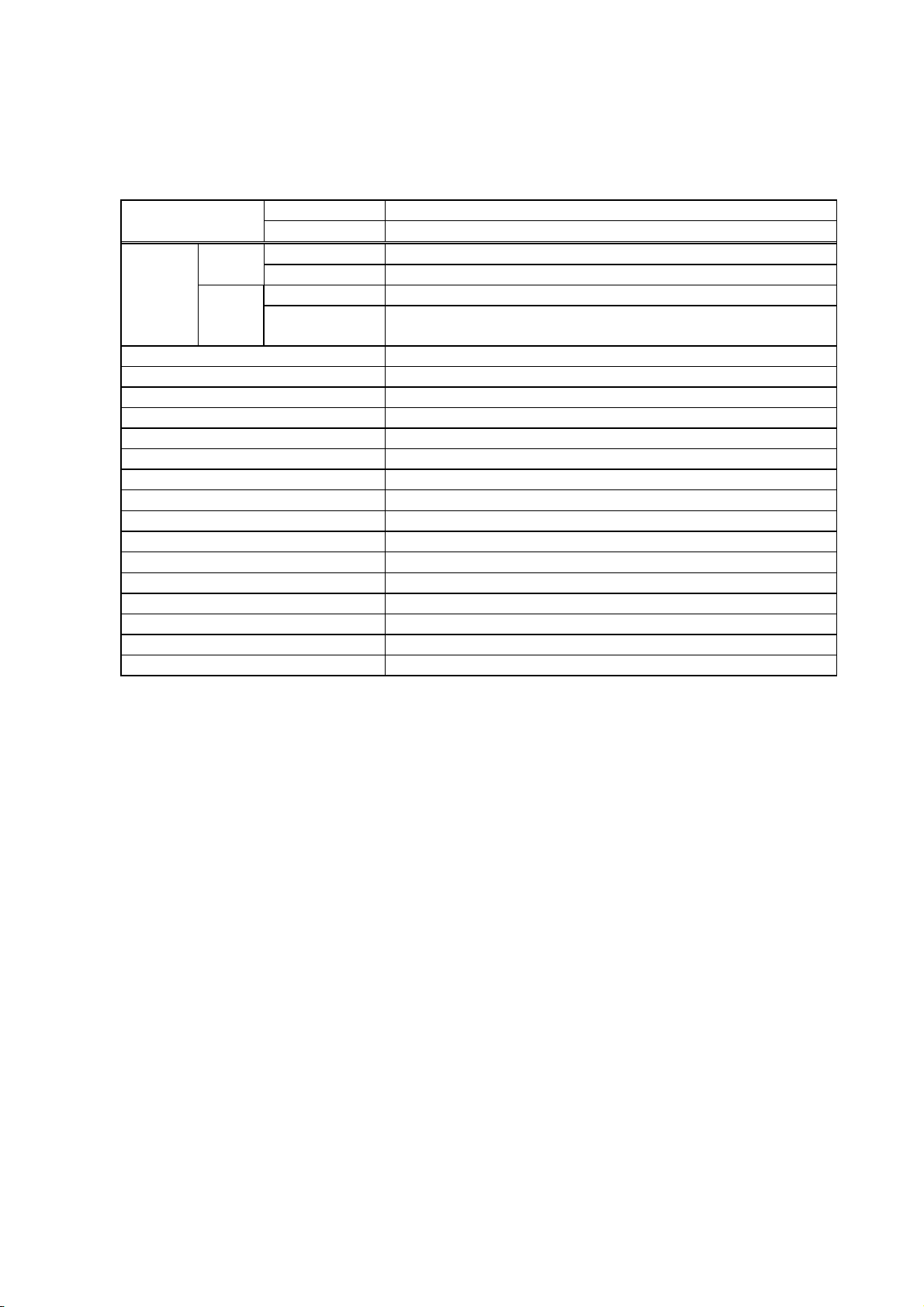
2.1.1 LE840T/LE850T 203 dpi/300 dpi
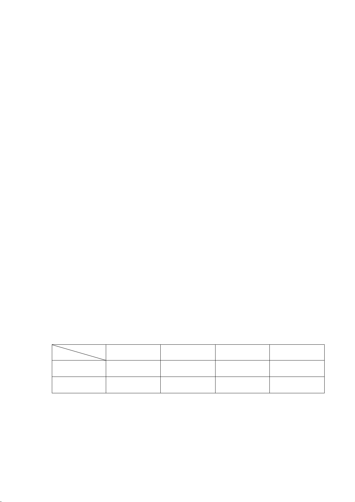
Model
Main 8 MB × 2 = 16 MB
Memory Whole 32 MB × 1 = 32 MB
Flash
ROM
SDRAM
Bitmap Kanji (Gothic)
Bitmap Kanji (Mincho)
Chinese
203 dpi LE840T
300 dpi LE850T
Font None
Image buffer of
whole SDRAM
203 dpi: 1.2 MB (Label length: 1500 mm)
300 dpi: 2.6 MB (Label length: 1500 mm)
None
None
None
RS-232C Option
Centronics Option
USB device (Function) Standard
100BASE wired LAN Standard
Wireless LAN Board Option
Ribbon save module None
Disc cutter module Option
Rotary cutter module None
Strip module Option
External rewinder None
Platen for narrow media None
Expansion I/O board Option
RTC+USB host Interface board Option
2-1
Page 8
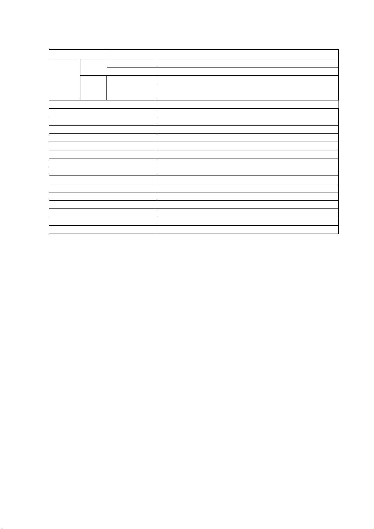
2.1.2 LE840D 203 dpi
Model 203 dpi LE840D
Main 8 MB × 2 = 16 MB
Flash
ROM
Font None
Memory Whole 32 MB × 1 = 32 MB
SDRAM
Bitmap Kanji (Gothic)
Bitmap Kanji (Mincho)
Chinese
Image buffer of
whole SDRAM
1.2MB (Label length: 1500 mm)
RS-232C Option
Centronics Option
USB device (Function) Standard
100BASE wired LAN Standard
Wireless LAN Board Option
Ribbon save module None
Disc cutter module Option
Rotary cutter module None
Strip module Option
External rewinder None
Platen for narrow media None
Expansion I/O board Option
RTC+USB host Interface board Option
None
None
None
2-2
Page 9
2.2 PRINT METHOD
Thermal transfer method
Direct thermal method
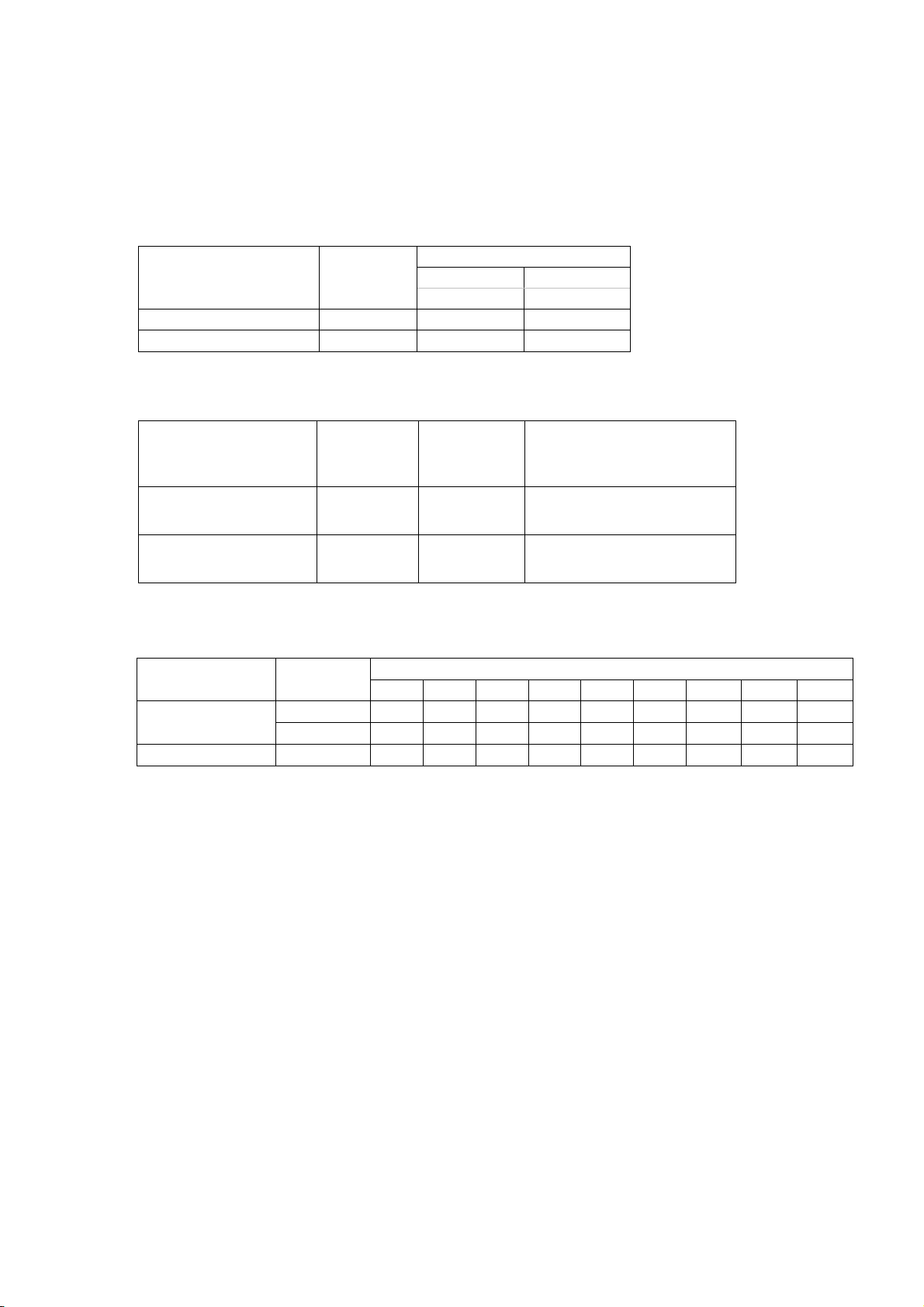
2.3 PRINT HEAD SPECIFICATION
Model
LE840T/LE850T Flat
LE840D Flat
2.4 PAPER ALIGNMENT
Model Resolution
LE840T/LE850T
LE840D 203 dpi Flat Side
2.5 PRINT SPEED
Model Resolution
LE840T/LE850T
LE840D 203 dpi
203 dpi
300 dpi
Print head
type
203 dpi/
300 dpi
2”/s 3”/s 4”/s 5”/s 6”/s 8”/s 10”/s 12”/s 14”/s
Resolution
203dpi 300dpi
8 dots/mm 11.8 dots/mm
Print head
type
Flat Side
Paper alignment
Print speed
2-3
Page 10

2.6 CHARACTERS
<Bitmap font> 203 dpi
Times Roman (Medium) 12 point
Times Roman (Medium) 15 point
Times Roman (Bold) 15 point
Times Roman (Bold) 18 point
Times Roman (Bold) 21 point
Times Roman (Italic) 18 point
Helvetica (Medium) 9 point
Helvetica (Medium) 15 point
Helvetica (Medium) 18 point
Helvetica (Bold) 18 point
Helvetica (Bold) 21 point
Helvetica (Italic) 18 point
Presentation (Bold) 27 point
Letter Gothic (Medium) 14.3 point
Prestige Elite (Medium) 10.5 point
Prestige Elite (Bold) 15 point
Courier (Medium) 15 point
Courier (Bold) 18 point
OCR-A 12 point
OCR-B 12 point
Gothic725 Black 6 pint
Kanji/External character (Gothic) 16 x 16 dots
Kanji/External character (Gothic) 24 x 24 dots
Kanji/External character (Gothic) 32 x 32 dots
Kanji/External character (Gothic) 48 x 48 dots
Kanji (Mincho) 24 x 24 dots
Kanji (Mincho) 32 x 32 dots
Chinese*1 24 x 24 dots
*1: Chinese fonts need to be installed.
<Outline font>
Fonts other than TrueType
font
OKI FONT 1, OKI FONT 2, Price Fonts 1, 2 and 3, DUTCH801
Bold, BRUSH738 Regular, Gothic 725 Black
TrueType font BalloonPExtBol, BlacklightD, BrushScrD, CG Times, CG Times
Bold, CG Times Italic, Clarendon Condensed Bold, FlashPBol,
Garamond Kursiv Halbfett, GoudyHeaP, GilliesGotDBol,
GilliesGotDLig, NimbusSanNovTUltLigCon, Ryahd, Ryahd
Bold, CG Triumvirate, CG Triumvirate Condensed Bold,
Univers Medium, Univers Bold, Univers Medium Ilalic, add_on
TrueTypeFont 1, add_on TrueTypeFont 2, add_on
TrueTypeFont 3, add_on TrueTypeFont 4, add_on
TrueTypeFont 5, Kanji add_on TrueTypeFont 1, Kanji add_on
TrueTypeFont 2, Kanji add_on TrueTypeFont 3, Kanji add_on
TrueTypeFont 4, Kanji add_on TrueTypeFont 5
NOTE: TrueType fonts need to be installed separately.
2-4
Page 11
2.7 BAR CODES/TWO-DIMENSIONAL CODES
<Bar codes> JAN8/EAN8, JAN13/EAN13, UPC-A, UPC-E, Interleaved 2 of 5,
NW7, CODE39, CODE93, CODE128, EAN128, MSI, GS1 DataBar,
Customer Barcode, POSTNET, RM4SCC, KIX CODE, Industrial 2
of 5, MATRIX 2 of 5 for NEC
<Two-dimensional codes> QR CODE, MicroQR CODE, PDF417, DataMatrix, Maxicode,
MicroPDF417, CP CODE
2.8 STORABLE FORMATS
Max. 99 types
2.9 WRITABLE CHARACTERS
Free size: 224 characters x 40 types
16 x 16 dots: 188 characters
24 x 24 dots: 188 characters
32 x 32 dots: 188 characters
48 x 48 dots: 188 characters
2.10 INTERFACE
RS-232C
Centronics (IEEE1284 compatible mode, Nibble mode)
LAN (100base)
Wireless LAN (IEEE802.11b/g)
USB V2.0
2.11 USB MEMORY (USB HOST)
Recommended USB memories
Size Manufacturer Type Function
1GB SP001GBUF2M01V1K
2GB SP002GBUF2M01V1K
8GB
SILICON POWER
SP008GBUF2M01V1K
2.12 SENSOR
Head open sensor
Head up sensor (Head lock sensor)
Transmissive sensor
Reflective sensor
Ribbon take-up motor sensor
Ribbon feed (back tension) motor sensor
Rewinder overflow sensor
Backing paper overflow sensor
Peel-off sensor
Head thermistor
Ambient temperature sensor
Readable
and writable
2-5
Page 12
2.13 KEYS
FEED key
PAUSE key
RESTART key
MODE key
CANCEL key
ENTER key
Up (↑) key
Down (↓) key
Left (←) key
Right (→) key
2.14 LED
ONLINE LED: Green
ERROR LED: Red
2.15 LCD
Type: Graphic LCD
Size: 128 dots (W) x64 dots (H)
Max. No. of characters displayed: 21 digits x 5 lines
2.16 ISSUE MODE
Batch: The specified number of labels is continuously issued in a batch.
Cut: The specified number of labels is issued while being cut at the specified cut interval.
Cut issue will be ignored if the cut issue is specified while the printer is in the peel-off
mode.
Peel-off: Next label will not be printed until the current label is removed from the strip shaft.
However, when the application is programmed so that the applicator of a labeler ignores
the peel-off sensor, subsequent labels are printed regardless of whether the current label
is removed or not.
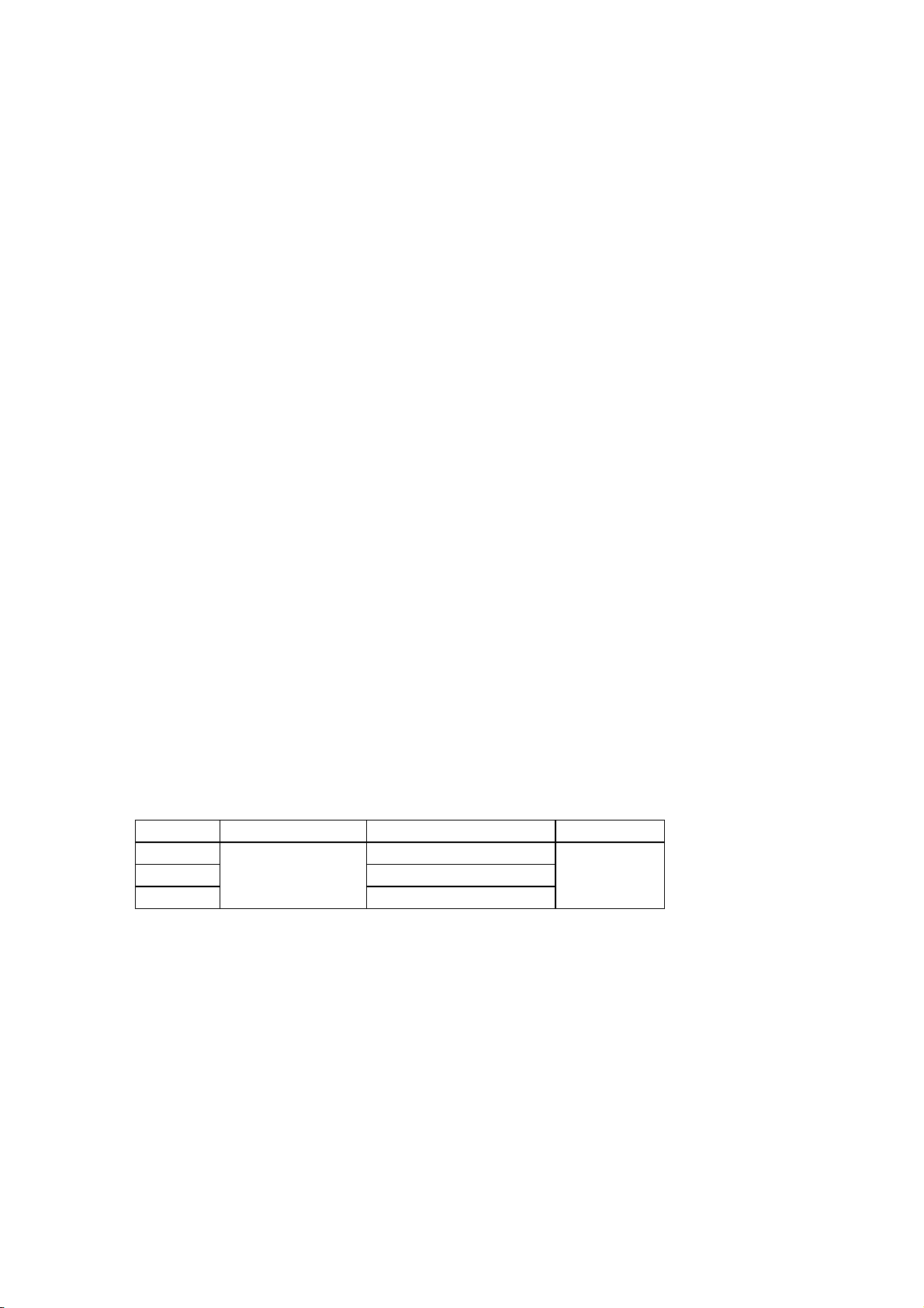
2.17 MEDIA
Size
Mode
LE840T/LE850T
203/300 dpi
LE840D
203 dpi
Label width
22 to 111mm 2 to 20mm 2 to 10mm 25 to 114mm
22 to 111 mm 2 to 20 mm 2 to 10 mm 25 to 114 mm
Gap between
labels
Black mark length
Backing paper
width
2-6
Page 13

2.18 CUT
Stop and cut with the disc cutter
Non-stop cut with the rotary cutter
2.19 RIBBON SAVING FUNCTION
When the ribbon saving function is enabled, the print head is raised when non-print area is detected
during printing. While the print head is raised, only the media is fed, causing ribbon loss to be
reduced. RIBBON save, Head up related parameter are included in system menu. However, this
function will not be supported by LE840/LE850. Therefore these parameter setting will be ignored and
no effect.
2.20 AUTO CALIBRATION
When the auto calibration function is enabled, the printer performs an auto calibration at a power on
time and the open/close of the print head. During the auto calibration, the threshold value, gap length,
label pitch, effective print length and whether the ribbon is used or not are automatically detected. The
printer performs subsequent printing based on the detected settings.
2.21 MANUAL HOME POSITION DETECTION
When the manual home position detection function is enabled, the printer feeds media to the print
start position after a power on, a batch reset (cause by Z0 command or W@ command), depression of
the FEED key which follows the closing of the print head block.
2-7
Page 14

3. INTERFACE
3.1 GENERAL DESCRIPTION
This chapter provides the detailed explanations of each interface between the host and the printer.
Interface types available to the LE840/LE850 series are as follows:
Standard: USB (FUNCTION) + LAN
Option: Wireless LAN
USB (HOST)
RS-232C
Centronics (IEEE1284)
NOTES: 1. When using RS-232C interface, the RS-232C cable shall be connected to the printer
before turning on the printer power.
2. The wireless LAN and the wired LAN cannot be used at the same time.
3-1
Page 15
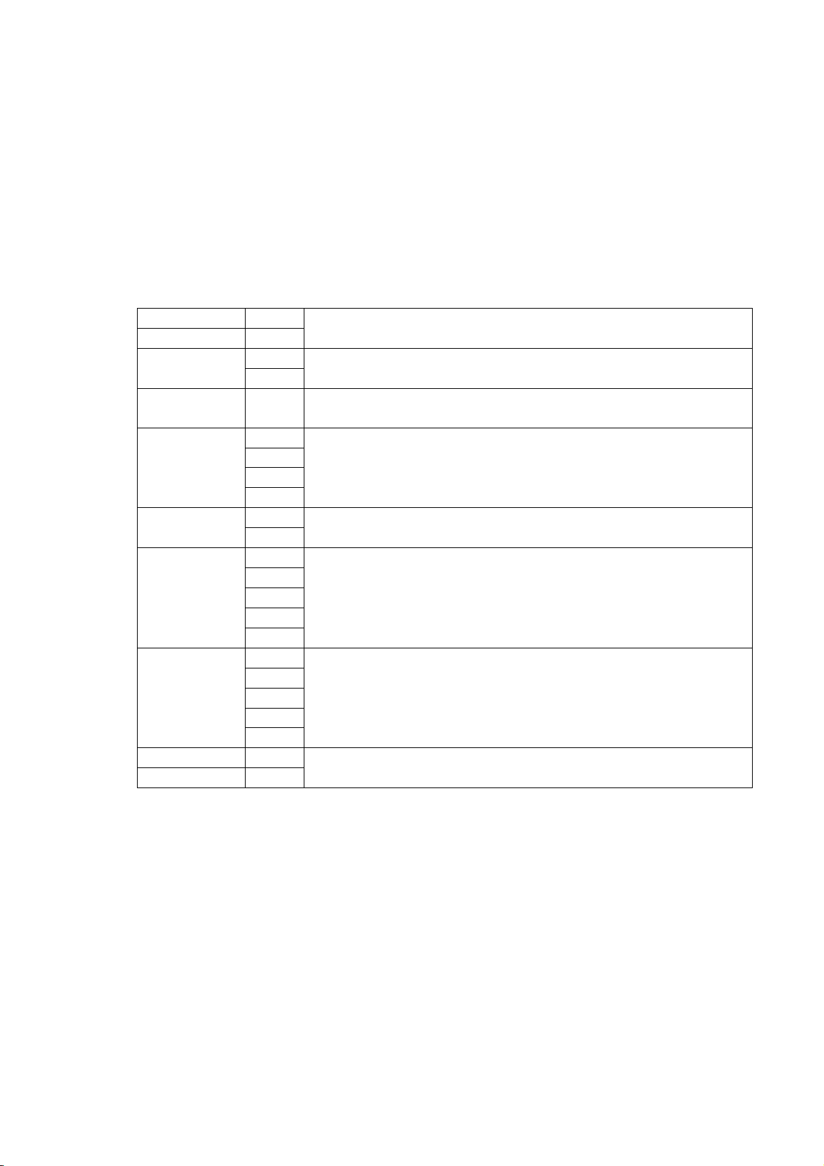
3.2 USB INTERFACE
(1) Applicable standard: Conforming to USB Standard Rev. 2.0
(2) Data Transfer Type: Control transfer, Bulk transfer
(3) Transfer Rate: Full speed (12Mbps)
(4) Transfer Control Method: A status is sent along with the receive buffer free space information in
response to a read request immediately after [ESC]WB[LF][NUL], as
described below. Based on this status response, the host computer
can transmit data so that the receive buffer does not become full.
Status with the receive buffer free space information
SOH 01H
STX 02H
3XH Status
3XH
Status type 33H Indicates that this status includes the receive buffer free space
Remaining
count
Free space of
receive buffer
Receive buffer
capacity
CR 0DH
LF 0AH
3XH
3XH
3XH
3XH
32H Length
33H
3XH
3XH
3XH
3XH
3XH
30H
30H
35H
31H
32H
Indicates the header of the status block
Printer status
*Details are described later
information.
Remaining number of labels to be printed
“0000” (0 labels) to “9999” (9999 labels)
Total number of bytes of this status block
“23” (23 bytes)
Free space of the receive buffer
“00000” (0K bytes) to “00512” (512K bytes)
However, the maximum value shall be the receive buffer capacity.
Receive buffer capacity
“00512” (512K bytes)
Indicates the terminator of the status block.
3-2
Page 16

3.3 NETWORK INTERFACE
(1) Configuration
On board
(2) Protocol: TCP/IP
(3) Network Specifications
LPR server function
WEB printer function
Socket communication function
FTP server function
Mail transmission/reception function
3-3
Page 17

3.4 SERIAL INTERFACE
(1) Type: Conforming to RS-232C
(2) Mode of Communication: Full duplex
(3) Transmission Speed: 2400 bps
4800 bps
9600 bps
19200 bps
38400 bps
115200 bps
(4) Synchronization Method: Start-stop synchronization
(5) Start Bit: 1 bit
(6) Stop Bit: 1 bit
2 bits
(7) Data Length: 7 bits
8 bits
(8) Parity: None
Even
Odd
(9) Error Detection: Parity error Vertical parity error check
Framing error This error occurs if no stop bit is found in the frame
specified starting with the start bit.
(10) Protocol: No-procedure method
(11) Data Input Code: ASCII code
European character set 8 bit code
Graphics 8 bit code
JIS 8 code
Shift JIS Kanji code
JIS Kanji code
UTF-8
(12) Receive Buffer: 1 MB
* The receive buffer is shared with other interfaces.
3-4
Page 18

(13) Transmission Control: XON/XOFF (DC1/DC3) Protocol
READY/BUSY (DTR) Protocol
XON/XOFF (DC1/DC3) Protocol + READY/BUSY (DTR) Protocol
READY/BUSY (RTS) Protocol
XON/XOFF (DC1/DC3) Protocol
● When initialized after the power is turned on, this printer becomes ready to receive data
and sends an XON code (11H). (Transmission or non-transmission of the XON code is
selectable by means of the parameter setting.)
● The printer sends an XOFF code (13H) when the free space in the receive buffer become
10 Kbytes or less.
● The printer sends an XON code (11H) when the free space in the receive buffer become
512 Kbytes or more.
● When there are no free space in the receive buffer, the printer discards data received
exceeding the receive buffer capacity, without storing it in the buffer. (After detecting the
XOFF code, the host computer must stop transmission before the printer receive buffer
becomes full.)
● The printer sends an XOFF code (13H) when the power is off. (Transmission or nontransmission of the XOFF code is selectable by means of the parameter setting.)
● The DTR signal is always “High” (READY).
● The RTS signal is always “High”.
READY/BUSY (DTR) Protocol
● When initialized after the power is turned on, this printer becomes ready to receive data
and turns the DTR signal to “High” level (READY).
● The printer turns the DTR signal to “Low” level (BUSY) when the free space in the receive
buffer become 10 Kbytes or less.
● The printer turns the DTR signal to “High” level (READY) when the free space in the
receive buffer become 512 Kbytes or more.
● When there are no free space in the receive buffer, the printer discards data received
exceeding the receive buffer capacity, without storing it in the buffer. (After detecting the
BUSY signal, the host computer must stop transmission before the printer receive buffer
becomes full.)
● The RTS signal is always “High”.
3-5
Page 19

XON/XOFF (DC1/DC3) Protocol + READY/BUSY (DTR) Protocol
● When initialized after the power is turned on, this printer becomes ready to receive data
and turns the DTR signal to “High” level (READY). The printer also sends an XON code
(11H).
● When the free space in the receive buffer become 10 Kbytes or less, the printer turns the
DTR signal to “Low” level (BUSY) and sends an XOFF code (13H).
● When the free space in the receive buffer become 512 Kbytes or more, the printer turns
the DTR signal to “High” level (READY) and sends an XON code (11H).
● When there are no free space in the receive buffer, the printer discards data received
exceeding the receive buffer capacity, without storing it in the buffer. (After detecting the
XOFF code or BUSY signal, the host computer must stop transmission before the printer
receive buffer becomes full.)
● The printer sends an XOFF code (13H) when the power is off.
● The RTS signal is always “High”.
READY/BUSY (RTS) Protocol
● When initialized after the power is turned on, this printer turns the RTS signal to “High”
(READY).
● The printer turns the RTS signal to “Low” (BUSY) when the free space in the receive buffer
become 10 Kbytes or less.
● The printer turns the RTS signal to “High” (READY) when the free space in the receive
buffer become 512 Kbytes or more.
● When there are no free space in the receive buffer, the printer discards data received
exceeding the receive buffer capacity, without storing it in the buffer. (After detecting the
BUSY signal, the host computer must stop transmission before the printer receive buffer
becomes full.)
● The DTR signal is always “High” (READY).
● The DSR signal from the host shall be always “High”.
* When the flow control is performed with a Windows PC, “READY/BUSY (RTS) protocol” shall
be selected, and “Hardware” shall be selected for the flow control in the Windows
communication port setting.
NOTE: For “READY/BUSY (DTR) protocol”, data shall be sent after 200 ms from when the
DTR signal is turned to “High” (READY). For “READY/BUSY (RTS) protocol”, data
shall be sent after 200 ms from when the RTS signal is turned to “High” (READY).
3-6
Page 20
(14) Input/Output Signals
It is in the Low (Mark) state when no transmission is in
ate when no transmission is in
/BUSY (DTR) protocol or XON/XOFF
It is at “Low” level when the receive buffer is near full, and
C3) protocol or READY/BUSY
It is an input signal indicating whether or not the data
transmission to the host is possible. However, this
It is at “Low” when the receive buffer is nearly full, and at
Printer
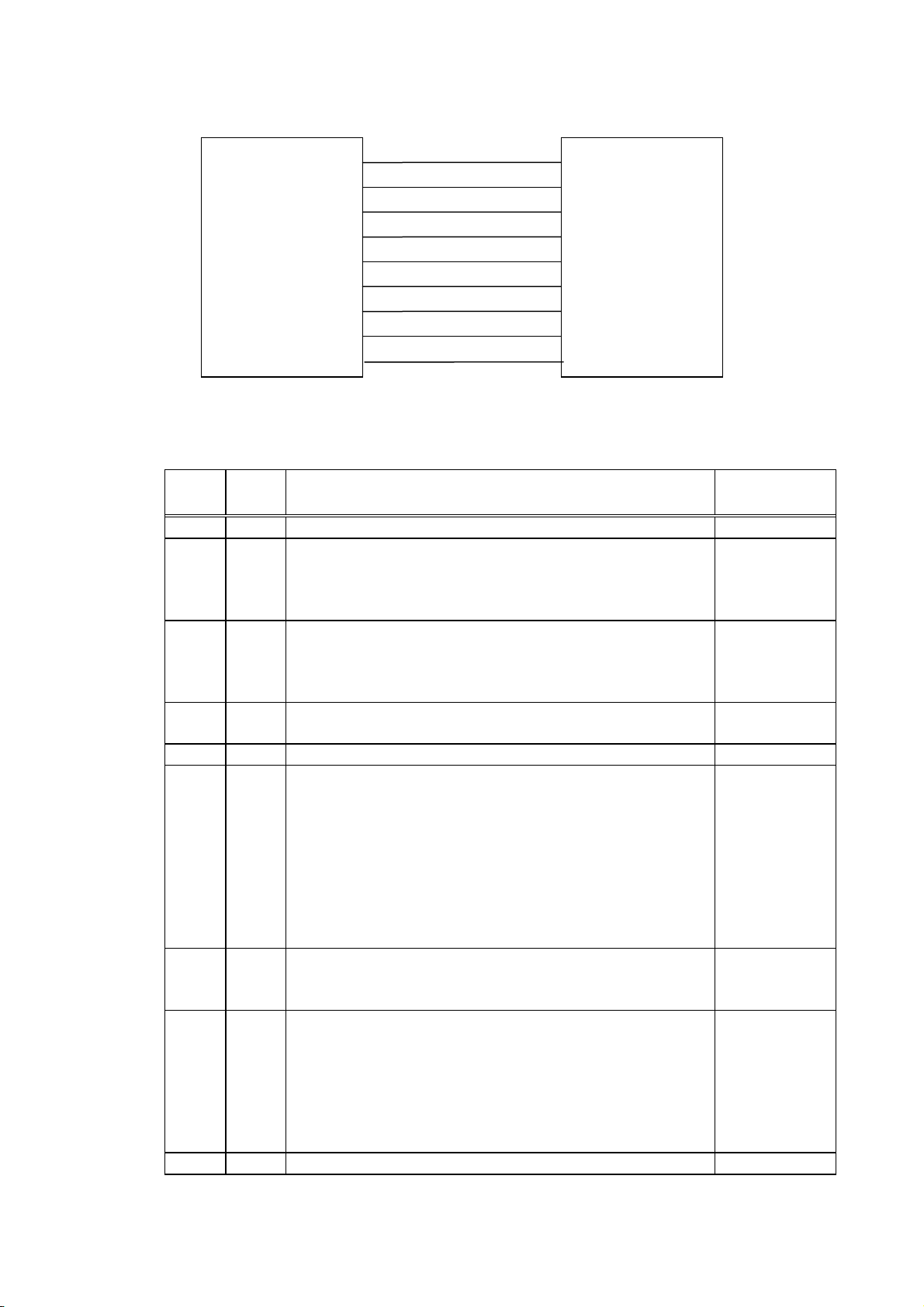
(15) Connector Pin Assignment and Signal Description
N.C
TD
RD
DSR
SG
DTR
CTS
RTS
N.C
Host
Pin No.
Signal
Name
1 NC No Connection
2 TD Data line from the printer to the host
Logic 1 is a Low level, while logic 0 is a High level.
progress.
3 RD Data line from the host to the printer
Logic 1 is a Low level, while logic 0 is a High level.
It is in the Low (Mark) st
progress.
4 DSR Input signal from the host
For the printer to receive data, it must be at “High” level.
5 SG Ground line for all data and control signals
6 DTR Output signal to the host
For the READY
(DC1/DC3) protocol + READY/BUSY (DTR) protocol:
It indicates the ready state for the received data.
at “High” level when near empty.
For the XON/XOFF (DC1/D
(RTS) protocol:
After the power is turned on, it is always at “High”.
7 CTS
Function Signal Direction
Printer →
← Host
← Host
Printer →
← Host
printer does not detect this signal.
8 RTS Output signal to the host
For the READY/BUSY (RTS) protocol:
It indicates the ready state for the received data.
“High” when nearly empty.
For protocol other than the READY/BUSY (RTS) protocol:
After the power is turned on, it is always at “High” level.
9 NC No Connection
Printer →
3-7
Page 21
DSR
DTR
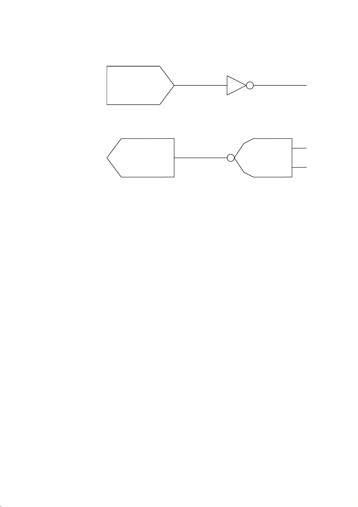
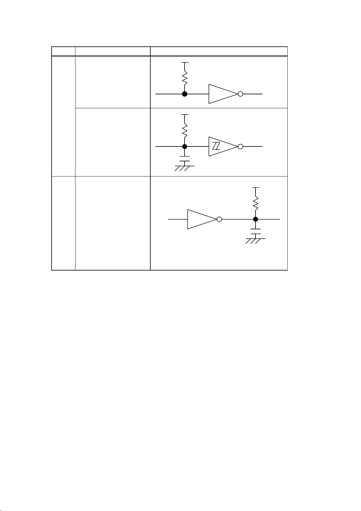
(16) Interface Circuit
Input Circuit
Output Circuit
Signal Levels
Input Voltage H ...... +3 to +15 V
Output Voltage H ......+6 to +13 V
RD
CTS
TD
RTS
L .......-3 to -15 V
L .......-6 to -13 V
SN75189 or equivalent
SN75188 or equivalent
3-8
Page 22

3.5 PARALLEL INTERFACE
(1) Type: Centronics
(2) Mode: Conforms to IEEE1284 Compatibility mode and Nibble mode
(3) Data Input Method: Parallel 8 bits (DATA1 to 8)
(4) Control Signals: Compatibility mode Nibble mode
nStrobe HostClk
nAck PrtClk
Busy PtrBusy
PError AckDataReq
Select Xflag
nAutoFd HostBusy
nInit nInit
nFault nDataAvail
nSelectIn IEEE1284Active
(5) Data Input Code: ASCII code
European character set 8 bit code
Graphics 8 bit code
JIS 8 code
Shift JIS Kanji code
JIS Kanji code
UTF-8
(6) Receive Buffer: 1 MB
* The receive buffer is shared with other interfaces.
3-9
Page 23
(7) Input/Output Circuit Configuration and Input/Output Conditions:
Signal Configuration
DATA1 to 8
+5V
1K
SN74LS245 or equivalent
Input nStrobe/HostClk/HostClk
nInit/nInit/
nReverseRequest
nAutoFd/HostBusy/
HostAck
nSelectIn/IEEE1284Active
/
IEEE1284Active
Busy/PtrBusy/PeriphAck
nFault/nDataAvail/
nPeriphRequest
nAck/PtrClk/PeriphClk
Select/Xflag/XFlag
Output
PError/AckDataReq/
nAckReverse
+5V
1K
100P
SN7406 or equivalent
SN74LS14 or equivalent
+5V
1K
100P
Logic level
(Input)
“1” = 2 to 5 V
“0” = 0 to 0.4
V
Logic level
(Input)
“1” = 2.4 to 5
V
“0” = 0 to 0.4
V
(8) Connector: Printer
Amp. Japan 552742-1 or equivalent
DDK 57RE-40360-73B or equivalent
Cable
Amp. Japan 552470-1 or equivalent
DDK 57E-30360 or equivalent
3-10
Page 24

(9) Connector Pin Diagram (IEEE1284-B Connector):
Pin
Signal Name
No. Compatibility Mode Nibble mode
1
nStrobe HostClk
2
Data 1 Data 1
3
Data 2 Data 2
4
Data 3 Data 3
5
Data 4 Data 4
6
Data 5 Data 5
7
Data 6 Data 6
8
Data 7 Data 7
9
Data 8 Data 8
10
nAck PtrClk
11
Busy PtrBusy
12
PError AckDataReq
13
Select Xflag
14
nAutoFd HostBusy
15
NC NC
16
0V 0V
17
CHASSIS GND CHASSIS GND
18
+5V (for detection) +5V (for detection)
19
TWISTED PAIR GND (PIN1) TWISTED PAIR GND (PIN1)
20
TWISTED PAIR GND (PIN2) TWISTED PAIR GND (PIN2)
21
TWISTED PAIR GND (PIN3) TWISTED PAIR GND (PIN3)
22
TWISTED PAIR GND (PIN4) TWISTED PAIR GND (PIN4)
23
TWISTED PAIR GND (PIN5) TWISTED PAIR GND (PIN5)
24
TWISTED PAIR GND (PIN6) TWISTED PAIR GND (PIN6)
25
TWISTED PAIR GND (PIN7) TWISTED PAIR GND (PIN7)
26
TWISTED PAIR GND (PIN8) TWISTED PAIR GND (PIN8)
27
TWISTED PAIR GND (PIN9) TWISTED PAIR GND (PIN9)
28
TWISTED PAIR GND (PIN10) TWISTED PAIR GND (PIN10)
29
TWISTED PAIR GND (PIN11) TWISTED PAIR GND (PIN11)
30
TWISTED PAIR GND (PIN31) TWISTED PAIR GND (PIN31)
31
nInit nInit
32
nFault nDataAvail
33
0V 0V
34
NC NC
35
NC NC
36
nSelectIn IEEE1284Active
NOTE: The signal name starting with a lower case “n” indicates that it is a low active signal.
3-11
Page 25

(10) Input/Output Signals :
Compatibility mode
Data 1 to 8 (Printer ← Host)
● Input data signals for the 1st to 8th bits.
● Logic 1 is “High” level.
● Min. data pulse width of 2.5 µsec.
nStrobe (Printer ← Host)
● Synchronizing signal for reading the above data.
● Normally at “High” level. The data is read at the rise of the Low level pulse.
● Minimum data pulse width of 0.5 µsec.
Busy (Printer → Host)
● This signal indicates that the printer is in a Busy state.
● When initialized after the power is turned on, the printer becomes ready to receive data
and turns the signal to “Low” level.
● The signal turns to “High” level (in a Busy state) when data is set from the host (at the fall
of the nStrobe signal).
● The signal turns to “Low” level when the printer reads the data.
● When the free space in the receive buffer become 512 bytes or less, the printer keeps the
signal at “High” level (in a Busy state) for 10 seconds when data is set from the host, to
extend the data read interval.
● When there are no free space in the receive buffer, the printer stops reading data. Then,
it keeps the signal at “High” level (in a Busy state) until there are free space in the receive
buffer when data is set from the host.
● The signal is kept at “High” level (in a Busy state) until the current state (one of the
following states) is reset.
• PAUSE state caused by the [PAUSE] key
• Paper end state
• Ribbon end state
• Head open state
• Printer error state
• Initialization in progress upon receipt of the nInit signal
nAck (Printer → Host)
● This signal indicates that the printer has read the data set by the host and is ready to
receive the next data.
● The signal is normally at “High”. It is at “Low” for about 5 µsec. after the fall of the BUSY
signal. The host should usually set data after the ACK signal is turned from “Low” to
“High”.
● If the nAck signal is ignored and the next data is set while the nAck signal is Low, the
“LOW” level continues about further 5 µsec at the fall of the BUSY signal. However, the
data can be received properly.
3-12
Page 26

nInit (Printer ← Host)
● Reset request signal from the host.
● Normally at “High” level. A low on this input causes the printer to be initialized in the
same manner as when the power is turned on.
* When “Reset process when the nInit signal is ON” is set to “OFF” in the parameter setting
in the system mode, the printer is not initialized even if it receives a low signal.
● When the nInit signal is input during printing, the printer completes printing one tag/label
which is being printed, cancels the next processing, then is initialized in the same manner
as when the power is turned on.
* When “Reset process when the nInit signal is ON” is set to “OFF” in the parameter setting
in the system mode, the next process proceeds without being canceled.
● Minimum pulse width of 0.5 µsec.
Select (Printer → Host)
● This is an output signal which indicates whether the printer is in Pause state or placed
online. The printer can receive data while placed online.
● The signal is at “Low” level while the printer is in a Pause state.
● The signal is kept at “Low” level (in a Pause state) until the current state (one of the
following states) is reset.
• Pause state caused by the [PAUSE] key
• Paper end state
• Ribbon end state
• Head open state
• Printer error state
• Initialization in progress upon power on or receipt of the nInit signal
nFault (Printer → Host)
● Output signal indicating that the printer is in a Fault state.
● At “Low” level while the printer is in a Fault state.
● The signal is kept at “Low” level (in a Fault state) until the current state (one of the
following states) is reset.
• Pause state caused by the [PAUSE] key
• Paper end state
• Ribbon end state
• Head open state
• Printer error state
• Initialization in progress upon power on or receipt of the nInit signal
PError (Printer → Host)
● Output signal indicating a label end or ribbon end state.
● At “High” level when the printer is in a label end or ribbon end state.
● Turns to “Low” level when the label end or ribbon end state is reset.
+5 V
● This is not a signal but a +5 V power supply voltage.
● The maximum current of 500 mA can be taken out.
nSelectIn (Printer ← Host)
● Not used
11
nAutoFd (Printer ← Host)
● Not used
3-13
Page 27

Nibble mode
PtrClk (Printer → Host)
● Reverse data transfer phase: It is used for evaluating data sent to the host.
● Reverse idle phase: When the printer changes the signal from Low to High, an
interrupt informing the host that the data is available, occurs
PtrBusy (Printer → Host)
● Reverse data transfer phase: Data bit 3 is used for the first transfer. Data bit 7 is used for
the second transfer. Indicates the forward channel is in a
Busy state.
AckDataReq (Printer → Host)
● Reverse data transfer phase: Data bit 2 is used for the first transfer. Data bit 6 is used for
the second transfer.
● Reverse idle phase: This signal is set to high until the data transfer is requested
by the host. Then, the process is performed according to
the nDataAvail signal.
Xflag (Printer → Host)
● Reverse data transfer phase: Data bit 1 is used for the first transfer. Data bit 5 is used for
the second transfer.
HostBusy (Printer ← Host)
● Reverse data transfer phase: It indicates that the host can receive data from the printer by
setting the signal to low. Then, the host sets the signal to
high, and sends the Ack indicating that the nibble data is
received. When the signal is set to low after the reverse
channel data transfer is performed, the interface phase
changes to the idle phase. At that time, there is no
available data on the printer.
● Reverse idle phase: When this signal is set to high according to the low pulse of
the PtrClk signal, the host enters the reverse data transfer
phase again. If this signal is set to high when the
IEEE1284 Active signal is low, the IEEE1284 idle phase
stops, and the interface enters the Compatibility mode.
nDataAvail (Printer → Host)
● Reverse data transfer phase: When the signal is low, it indicates the printer has data to be
sent to the host. And it is used for sending data bits 0 and
4.
● Reverse idle phase: It is used for indicating that the data is available.
3-14
Page 28
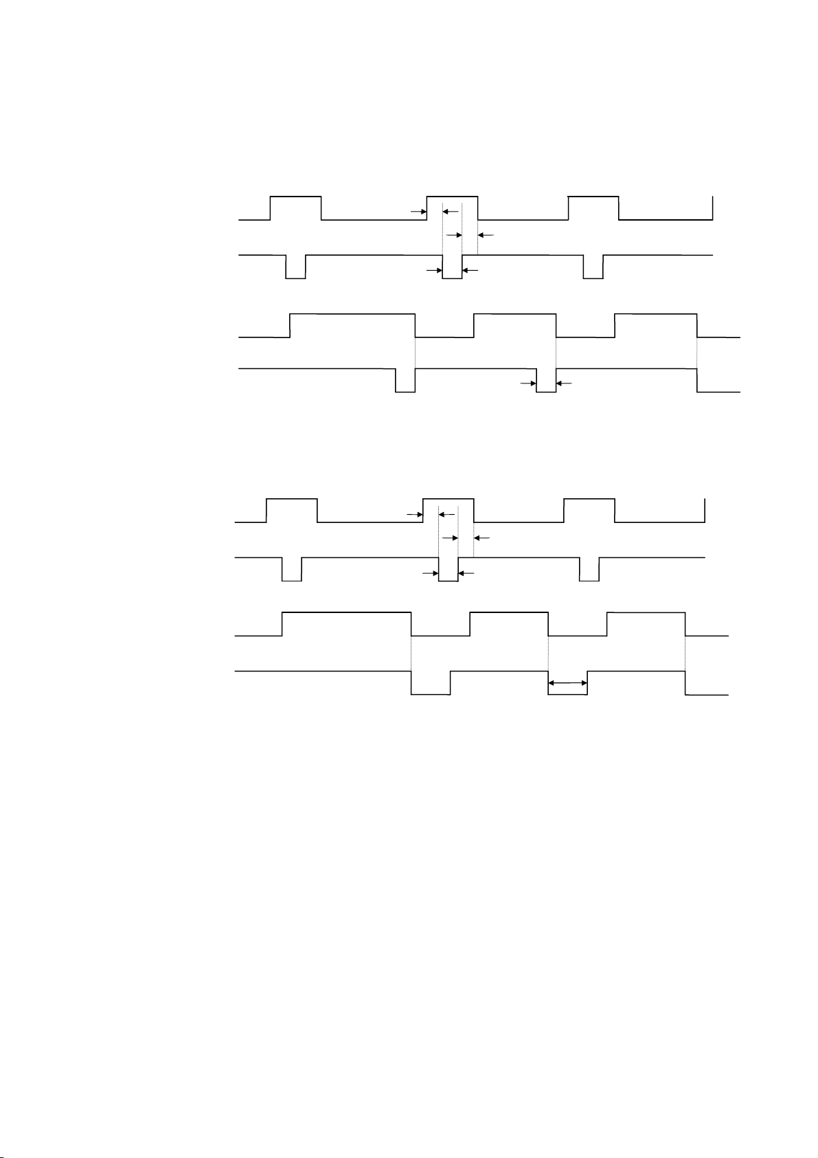
(11) Timing Chart
Approx. 5 µsec
Approx. 1 µsec
When receiving normal data:
For the Compatibility mode, one of two types of timing for BUSY-ACK can be selected.
a) Timing 1 (Default)
Data 1 to 8
(Host → Printer)
Min. 1 µsec
Min. 1 µsec
nStrobe
(Host → Printer)
Min. 0.5 µsec
Busy
(Host ← Printer)
nAck
(Host ← Printer)
b) Timing 2
Data 1 to 8
(Host → Printer)
Min. 1 µsec
Min. 1 µsec
nStrobe
(Host → Printer)
Min. 0.5 µsec
Busy
(Host ← Printer)
nAck
(Host ← Printer)
3-15
Page 29
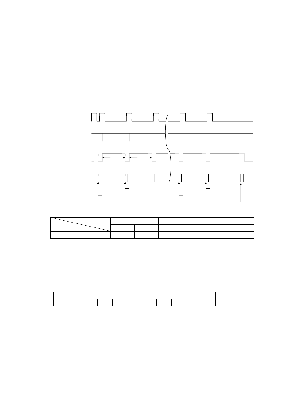
Receiving data in the Compatibility mode when the free space in the receive buffer is 512
1 blank byte
bytes or less:
● When the free space in the receive buffer becomes 512 bytes or less, the printer stores all
of the already received data in the receive buffer, stays in a Busy state (Busy signal at
“High” level) for 10 seconds to extend the data read interval when data is set from the host,
then reads the data 10 seconds later.
● If the free space becomes 513 bytes or more while waiting for the data read, the printer will
receive the data with the normal data receive timing.
● When there is no free space in the receive buffer, the printer stops reading data. Then, it
stays in a Busy state (Busy signal at “High” level) until a free space is generated in the
receive buffer after data is set from the host.
Data 1 to 8
(Host → Printer)
nStrobe
(Host → Printer)
Busy
(Host ← Printer)
nAck
(Host ← Printer)
512 blank bytes
10 sec 10 sec
511 blank
0 blank byte
1 blank byte
(12) Relationship between Printer Setting and PC Setting and Their Operation Modes
Host setting
Printer setting Compatibility
Windows95/98/Me WindowsNT4.0 Windows2000/XP
ECP
Compatibility
ECP
Compatibility
Compatibility mode (SPP) SPP SPP SPP SPP SPP SPP
* SPP mode operations include support of the Nibble mode.
* When SPP mode is selected for the printer setting, the printer returns a 13-byte status
(described at the top of the next page) to the Nibble mode negotiation immediately after [ESC]
WS [LF] [NUL] is received. The printer returns a 23-byte status with the receive buffer free
space information (described in (13) on the next page) to the Nibble mode negotiation
immediately after [ESC] WB [LF] [NUL] is received.
Status to be returned immediately after [ESC]WS[LF][NUL] is received (13 bytes):
SOX STX
Status Remaining count ETX EOT CR LF
01H 02H 3XH 3XH 3XH 3XH 3XH 3XH 3XH 03H 04H 0DH 0AH
ECP
3-16
Page 30
(13) Status with the receive buffer free space information
Indicates that the status includes the receive buffer free space
However, the maximum value differs depending on the models.
The printer returns a status along with the receive buffer free space information to the Nibble
mode negotiation immediately after [ESC] WB [LF] [NUL] is received, as described blow.
Status to be returned immediately after [ESC] WB [LF] [NUL] is sent (23 bytes):
SOH 01H Indicates the header of the status block
STX 02H
Status 3XH Printer status
3XH * Details are to be hereinafter described.
Status type 33H
information.
Remaining 3XH Remaining number of labels to be printed
count 3XH * Details are to be hereinafter described.
3XH
3XH
Length 3XH Total number of bytes of this status block.
3XH
Free space 3XH Free space of the receive buffer
of receive buffer 3XH “00000” (0 Kbyte) to “99999” (99999 Kbytes)
3XH However, the maximum value shall be the receive buffer
3XH capacity.
3XH
Receive buffer 3XH Receive buffer capacity
capacity 3XH “00000” (0 Kbyte) to “99999” (99999 Kbytes)
3XH
3XH
3XH
CR 0DH Indicates the terminator of the status block.
LF 0AH
3-17
Page 31

3.6 USB HOST INTERFACE
(1) Applicable standard: Universal Serial Bus V1.1
(2) Transfer Rate: Low speed (1.5 Mbps) and Full speed (12 Mbps)
(3) Others: Conforming to OpenHCI version 1.0 register set
Root hub
3-18
Page 32

3.7 WIRELESS LAN
3.7.1 Specification of Wireless LAN Module
(1) Applicable standard: IEEE802.11b/g
(2) Communication distance: 100 m/360° (Depending on conditions)
(3) Client protocol:
Physical layer 802.11b/g
Data link layer CSMA/CA
Network layer IP, ICMP, ARP
Transport layer TCP, UDP
Application layer SOCKET, LPR, SNMP agent, DHCP client, Web server, WINS
client
(4) Flow control TCP/IP flow control
(5) Antenna Built-in
(6) Parameter setting Via USB
(7) Parameter status monitoring Via HTTP
3.72 MAC address
When the wireless LAN module has been installed on the printer, the printer prints the MAC
address and wireless LAN module’s parameter settings.
[MAC address]
The MAC address is printed on the self-test result in the system mode.
For details, refer to LE840/LE850 Key Operation Manual.
3.7.3 Connection sequence
The connection sequence varies depending on the wireless LAN mode.
(1) Infrastructure Mode
The printer performs active scanning for all the supported channels at a power ON time using
the ESSID specified in advance. When the printer receives a valid active scanning response
from the access point, it enters the connection state.
The channel to be used is the one set on the access point.
The printer which is out of the connection state repeats the active scanning every 40 seconds
until it enters the connection state.
If the printer comes into a situation where it cannot receive the beacon from the access point for
a specified period of time after the connection due to weaker radio signals or other factors, the
printer goes out of the connection state. In this case, just as at a power ON time, the printer
waits for 40 seconds and then performs active scanning every 40 seconds until it is connected
again. This operation continues up to two hours.
When Supplicant is used, the 802.1x authentication is performed when the access point needs
to authenticate the printer which tries to connect to the access point (the timing differs
depending on the authentication method and access point specification.)
3-19
Page 33

when the same ESSID
is assigned.
If the printer failed in connection to an access point due
when the same ESSID
is assigned.
The
printer tries an active scanning, and connects to the
Channel 1
Roaming is enabled
Channel 2
(a) Example: Active scanning retry
to weak radio signals in spite of an active scanning with
ESSID “ABC”, the printer retries every 40 seconds.
ESSID (Extended Service Set ID): One of the identifiers
identifying a name of a wireless access point. It is named by a
user.
BSSID (Basic Service Set ID): One of the identifiers, generally
identifying the MAC address of an access point in the case of
BSS networks. It is not changeable by a user.
Note: Direct communication with wireless device is not allowed
when BSSID is different.
Channel 1
Roaming is enabled
Channel 2
network of BSSID: X1 when it receives a valid response
from the access point assigned with BSSID: X1.” The
channel to be used is the one used by the connected
access point.
(b) Example: Successful connection
3-20
Page 34

(2) Adhoc Mode
a joiner with ESSID:
ABC. When the printer cannot receive a valid response from
the creator, it becomes a creator and creates an IBSS network.
At this time, the printer refers to its own setup data for the
The printer performs active scanning for all the supported channels at a power ON time using
the ESSID set by a user in advance. When the printer receives a valid active scanning
response from the IBSS creator, the printer connects to the network as a joiner. The channel
set on the IBSS creator is used.
If the printer can receive no valid response after an approximately 3.5-second active scanning
for all the channels for , the printer becomes the IBSS creator and creates own BSS (a network
having a unique BSSID) for the channel specified for the printer.
The above operation enables a group of remotely-located wireless LAN clients (printers, handy
terminals, etc.) to share the same ESSID as well as each client of the group to become a
different network having unique BSSID. Since a communication is not allowed with the
network having different BSSID, wireless devices used in pairs are required to try connection
within a near area to avoid joining the network with different BSSID.
When the printer detects that there is a network having different BSSID but the same ESSID or
the IBSS creator exited from the network during periodic IBSS network monitoring, it tries reconnection to an optimum IBSS network. At this time, a connection may become unstable
temporarily.
Channel 1
ESSID (Extended Service Set ID): One of the identifiers,
identifying a name of a wireless access point. It is named by a
user.
BSSID (Basic Service Set ID): One of the identifiers, identifying
a wireless network. In the case of IBSS networks, it is named by
the creator.
Note: Direct communication with wireless device is not allowed
when BSSID is different.
The printer tries an active scanning as
channel to be used.
(a) Example: Joiner becomes creator
3-21
Page 35

Re-connection is
enabled when the same
ABC. When the printer receives a valid response from the
becomes a creator and creates an IBSS network.
At this time, the printer refers to its own setup data
After that, moving this n
ESSID is assigned
.
Channel 1
Channel 2
Move (Re-connection?)
The printer tries an active scanning as a joiner with ESSID:
creator, it connects to the IBSS created by the creator.
ESSID (Extended Service Set ID): One of the identifiers,
identifying a name of a wireless access point. It is named by a
user.
BSSID (Basic Service Set ID): One of the identifiers, identifying
a wireless network. In the case of IBSS networks, it is named by
the creator.
Note: Direct communication with wireless device is not allowed
when BSSID is different.
If the printer cannot receive a valid response from
the creator after performing an active scanning as
a joiner with ESSID “ABC”, the printer itself
for the channel to be used.
ew network into the cell of
BSSID: X1 network may cause the BSSID to
change to BSSID: X1.
Note: It depends on the device type.
(a) Example: Dynamic change of IBSS network
3.7.4 Received data handling when the printer enters the power save mode
Since the receive buffer has not been initialized, data sent before a timeout (power save mode)
remains in the receive buffer.
3-22
Page 36

4. TRANSMISSION SEQUENCE
<New>
flash ROM or USB
No
on the
4.1 PREPARATORY SETTING
External characters, logos, and PC interface commands need be stored in the printer before
performing label issue operations.
(1) Storing writable characters and logos
(Add/change)
● Storing PC interface commands
● Label issue operation
Power ON
No
Yes
Format Command
Bitmap Writable
Character Command
Completion of storing
all characters
Yes
[ESC] J1/[ESC] JA:
Formats the on-board
memory.
[ESC] XD/[ESC] XA:
Stores writable characters or logos
on-board flash ROM or USB memory.
NOTES: (1) The storage of writable characters or logos is unnecessary when they are not used.
(2) When the on-board flash ROM is used for storage, the memory will be consumed each
time already stored writable characters or logos are saved unless the Format
Command is sent in advance.
(3) When another operation (storing PC interface commands or label issue operation) is
performed after storing writable characters or logos, the image buffer will be cleared
automatically.
(4) If a subsequent storage of writable characters or logos does not take place, the printer
automatically enters the online mode (label issue operation) in about 10 seconds. At
this time, the image buffer will be cleared automatically.
4-1
Page 37

(2) Storing PC interface commands
flash
●
Label issue operation
No
Declares the start of saving PC
Declares the termination of saving PC
(Add/change)
Power ON
No
<New>
Yes
Format Command
Save Start Command
Label Size Set Command
Position Fine Adjust Command
Print Density Fine Adjust
Command
Image Buffer Clear Command
[ESC] J1/[ESC] JA: Formats the on-board
ROM or USB memory.
[ESC] XO/[ESC] XV:
interface commands.
[ESC] D: Sets the label size.
[ESC] AX: Adjusts the feed length, cut position, and
back feed length.
[ESC] AY: Adjusts the print density.
[ESC] C: Clears the image buffer.
Line Format Command
[ESC] LC: Sets the line format and draws it.
Bit Map Font Format Command
Outline Font Format Command
Bar Code Format Command
[ESC] PC: Sets the bit map font format.
[ESC] PV: Sets the outline font format.
[ESC] XB: Sets the bar code format.
Bit Map Font Data Command
Save Terminate Command
● Storing writable characters or logos
Completion of
storage
Yes
[ESC] RC: Specifies the data for the bit map font.
[ESC] XP:
interface commands.
NOTES: (1) The storage of writable characters or logos is unnecessary when they are not used.
(2) When the on-board flash ROM is used for storage, the memory will be consumed each
time already stored PC interface commands are saved, unless the Format Command is
sent in advance.
(3) When a different operation (storing writable characters or logos or label issue operation)
is performed after storing PC interface commands, the image buffer will be cleared
automatically.
(4) Stored commands shall be selected as needed.
(5) If a subsequent storage of PC interface commands does not take place, the printer
automatically enters the online mode (label issue operation) in about 10 seconds. At
this time, the image buffer will be cleared automatically.
4-2
Page 38

4.2 LABEL ISSUE OPERATION
Adjust Command
Yes
An example of the label issue operation is shown below.
(1) When the Saved Data Call Command is not used:
Label Size Set Command
Position Fine Adjust Command
Image Buffer Clear Command
Bitmap Font Format Command
Outline Font Format Command
Bar Code Format Command
Power ON
Place paper
Print Density Fine
Feed Command
Line Format Command
[ESC] D: Sets the label size.
[ESC] AX: Adjusts the feed length, cut position, and
back feed length.
[ESC] AY: Adjusts the print tone.
[ESC] T: Feeds one label and aligns it with the print
start position.
[ESC] C: Clears the image buffer.
[ESC] LC: Sets the line format and draws it.
[ESC] PC: Sets the bit map font format.
[ESC] PV: Sets the outline font format.
[ESC] XB: Sets the bar code format.
NOTES: (1) Whenever a paper type is changed, the Label Size Set Command and the Feed
(2) After the power is turned off and on, the Bit Map Font Format Command, the Outline
Bitmap Font Data Command
Outline Font Data Command
Bar Code Data Command
Issue Command
Yes
<Data change>
No
<Format change>
Yes
<Label change>
Power OFF
Command must be sent. When the same paper continues to be used after the power
is turned off and on, the Label Size Set Command and the Feed Command may be
omitted.
Font Format Command, and the Bar Code Format Command shall be sent as occasion
demands because they are not backed up in the memory.
No
No
[ESC] RC: Draws bitmap font data.
[ESC] RV: Draws outline font data.
[ESC] RB: Draws bar code data.
[ESC] XS: Issues (prints) the label.
4-3
Page 39

(2) When the Saved Data Call Command is used:
Calls the label format stored in
board flash ROM or
and aligns it with the print
Saved Data Call Command
Bitmap Font Data Command
Outline Font Data Command
Bar Code Data Command
Yes
Yes
Power ON
Place paper
Feed Command
Issue Command
<Data change>
No
<Label change>
[ESC] XQ/[ESC]XT:
the onUSB memory.
[ESC] T: Feeds one label
start position.
[ESC] RC: Draws bitmap font data.
[ESC] RV: Draws outline font data.
[ESC] RB: Draws bar code data.
[ESC] XS: Issues (prints) the label.
NOTES: (1) Whenever a paper type is changed, the Feed Command must be sent. When the
(2) When “automatic call at power on” has been selected in the Saved Data Call
(3) When XML data is used, print data in XML format can be sent to the printer.
Power OFF
same paper continues to be used after the power is turned off and on, the Feed
Command may be omitted.
Command, the Saved Data Call Command may be omitted after the power is turned off
and on.
For details, refer to the XML Data Print Specification.
No
4-4
Page 40

5. INTERFACE COMMANDS
30 30 43 33 32 0A 00
5.1 GENERAL DESCRIPTION
5.1.1 Format of Interface Command
ESC
The length from [ESC] to [LF] [NUL] must be as specified by each command.
There are the following three kinds of control codes:
ESC (1BH), LF (0AH), NUL (00H)
{ (7BH), | (7CH), } (7DH)
Code set in the system mode
5.1.2 How to Use Reference
Function Describes the outline of the function of the command.
Format Shows the format of the command.
Command & Data LF NUL
The format designation method shall conform to the following rules:
Each set of small letters (such as aa, bbbb) indicates parameters.
An item enclosed in parentheses may be omitted.
“…” indicates the repetition of an item.
Brackets and parentheses are used only in coding, and must not be transmitted
in practice.
Other symbols must always be inserted at designated positions before being
transmitted.
Term Explains the term(s) used in the format.
* “0 to 999” described in the entry range indicates that up to 3-digit variable-length
entry is allowed. (Entry of “001” or “009” is also possible.) “000 to 999” indicates
that the entry must be fixed as 3 digits.
Explanation Explains the command in detail.
Note Supplementary explanation of the command
Refer to Related commands
Examples Explains the command examples.
The above corresponds to the transfer of the following:
[ESC] T20C30 [LF] [NUL]
1B 54
[ESC] T 2 0 C 3 0 [LF] [NUL]
5-1
Page 41

5.1.3 Precautions
•
The commands and parameters described in this specification must always be used.
•
If any other command or parameter than those covered in this specification are used, the printer
operation will not be guaranteed.
•
The commands shall be used in the online mode.
•
If any command is transmitted in the system mode, the printer will not operate.
NOTES:
(1) When a command cannot be recognized as a command, it will be ignored.
(Example) [ESC]H, [ESC]AA, etc.
(2) When an entered value does not meet the specified number of digits, a command error occurs.
(Example) A 5-digit value is entered for the parameter fixed to 4 digits.
(3) When an improper type of value was entered for a parameter, a command error occurs.
(Example 1) “000A” is entered though “0001” must be set.
(Example 2) “1” is entered though “A” must be set.
(Example 3) “3” is entered though a number must be selected from “0”, “1” and “2”.
(4) When an entered value exceeds the specified range, a command error occurs.
However, this is not applicable to the Label Size Set Command. See the section describing the
Label Size Set Command ([ESC]D.)
(5) When no data is set for non-omissible parameter, a command error occurs.
5-2
Page 42

5.1.4 List of Commands
(1) Commands related to setting
Label Size Set Command [ESC] D...................................5
(2) Commands related to fine adjustment
Position Fine Adjust Command [ESC] AX ..............................18
Print Density Fine Adjust Command [ESC] AY ..............................28
Ribbon Motor Drive Voltage Fine Adjust Command [ESC] RM..............................30
(3) Commands related to clear
Image Buffer Clear Command [ESC] C.................................31
Clear Area Command [ESC] XR ..............................32
(4) Commands related to drawing format setting
Line Format Command [ESC] LC...............................34
Bit Map Font Format Command [ESC] PC ..............................38
Outline Font Format Command [ESC] PV ..............................54
Bar Code Format Command [ESC] XB ..............................71
(5) Commands related to print data
Bit Map Font Data Command [ESC] RC............................135
Outline Font Data Command [ESC] RV ............................135
Bar Code Data Command [ESC] RB ............................138
(6) Commands related to issue and feed
Issue Command [ESC] XS ............................154
Feed Command [ESC] T...............................174
Eject Command [ESC] IB..............................184
Forward/Reverse Feed Command [ESC] U1, [ESC] U2 ...........186
(7) Commands related to writable characters
Storage Area Allocate Command [ESC] XF.............................189
Flash Memory Format Command [ESC] J1 .............................192
External Memory Format Command [ESC] JA .............................193
2-byte Writable Character Code Range Command [ESC] XE ............................194
Bit Map Writable Character Command (for flash memory) [ESC] XD ............................195
Bit Map Writable Character Command (for external memory) [ESC] XA ............................197
(8) Commands related to graphics
Graphic Command [ESC] SG............................208
(9) Commands related to PC command saving
Save Start Command (for flash memory) [ESC] XO............................216
Save Start Command (for external memory) [ESC] XV ............................217
Save Terminate Command [ESC] XP ............................219
Saved Data Call Command (for flash memory) [ESC] XQ............................220
Saved Data Call Command (for external memory) [ESC] XT.............................221
5-3
Page 43

(10) Commands related to check
Head Broken Dots Check Command [ESC] HD ............................222
(11) Commands related to display
Message Display Command [ESC] XJ .............................259
(12) Commands related to control
Reset Command [ESC] WR ...........................225
Batch Reset Command [ESC] Z0 .............................226
(13) Commands related to status
Status Request Command [ESC] WS ...........................227
Receive Buffer Free Space Request Command [ESC] WB ...........................228
Version Information Acquire Command [ESC] WV ...........................229
External Memory Information Acquire Command [ESC] WI.............................230
External Memory Writable Character Information
Acquire Command [ESC] WG...........................232
Printer Option Status Acquire Command [ESC] WN ...........................233
(14) Commands related to TCP/IP setting
IP Address Set Command [ESC] IP..............................234
Socket Communication Port Set Command [ESC] IS..............................235
DHCP Function Set Command [ESC] IH..............................236
(15) Commands related to internal serial interface
Pass-through Command [ESC] @002 .......................237
Internal Serial Interface Parameter Set Command [ESC] IZ..............................238
(16) Commands related to parameter setting
Parameter Set Command [ESC] Z2;1..........................239
Fine Adjustment Value Set Command [ESC] Z2;2..........................243
RFID Parameter Set Command [ESC] Z2;3 ..........................245
(17) Commands related to RFID
RFID Tag Position Adjustment Command [ESC] @003 .......................247
RFID Tag Read Command [ESC] WF............................249
RFID Void Pattern Print Command [ESC] @006 .......................253
RFID Data Write Command [ESC] @012 .......................254
(18) Commands related to Real Time Clock
Real Time Clock (RTC) Set Command [ESC] JT .............................263
5-4
Page 44

5.2 COMMANDS RELATED TO SETTING
5.2.1 LABEL SIZE SET COMMAND [ESC]D
Function Sets the size of a label or tag.
Format [ESC] Daaaa,bbbb,cccc(,dddd)[LF][NUL]
Term aaaa: Pitch length of the label or tag
4 or 5 digits (in 0.1 mm units)
4 digits: 0100 (10.0 mm) to 9999 (999.9 mm)
5 digits: 00100 (10.0 mm) to 15000 (1500.0 mm)
bbbb: Effective print width
Fixed to 4 digits (in 0.1 mm units)
0100 (10.0 mm) to 1040 (104.0 mm)
cccc: Effective print length
4 or 5 digits (in 0.1 mm units)
4 digits: 0060 (6.0 mm) to 9999 (999.9 mm)
5 digits: 00060 (6.0 mm) to 14980 (1498.0 mm)
dddd: Backing paper width (Omissible. When omitted, the initial value is used as the
effective print width.)
Fixed to 4 digits (in 0.1 mm units)
0300 (30.0 mm) to 1120 (112.0 mm)
5-5
Page 45

Explanation
[Print direction:
T
op first]
[Labels]
[
Print
direction:
B
ottom first]
[Tag
paper
]
[Print direction:
B
ottom first]
[Print direction:
T
op first]
Origin of
coordinates
(0, 0)
Effective
print length
0
Y
Origin of
coordinates
(0, 0)
Backing paper width
Backing paper
Label
Label
pitch
X
Effective
print width
Paper feed direction
Black mark
(Back side)
Tag
Effective
print length
X
Y
0
Backing paper width
Effective
print width
Paper feed direction
Backing paper
Label
Label
pitch
Origin of
coordinates
(0, 0)
Black mark
(Back side)
Tag
Effective
print length
0
Y
Tag
pitch
X
Effective
print width
Paper feed direction
Effective
print length
X
Y
0
Effective
print width
Paper feed direction
Tag
pitch
Origin of
coordinates
(0, 0)
5-6
Page 46

Determination of the origin of coordinates (0, 0)
print length
guides
Type 1 [Top first printing]
How to determine the coordinate
origin in the X direction
Move a point in the X direction,
from the center of the effective
print width toward the right edge of
the label, as viewed from the front
of the printer.
How to determine the coordinate
origin in the Y direction
Move the point in the Y direction,
from the center of both the label
pitch and the effective print length
toward the top edge of the label,
as viewed from the front of the
printer.
Media guide
(Movable)
Inter-label
gap
Max. distance
between the media
Effective
Label pitch
Origin of coordinates (0, 0)
Effective print width
Media guide (Movable)
Type 1 [Bottom first printing]
How to determine the coordinate
origin in the X direction
Move a point in the X
direction, from the center of
the effective print width
toward the left edge of the
Origin of coordinates (0, 0)
label, as viewed from the
front of the printer.
How to determine the coordinate
origin in the Y direction
Move the point in the Y direction,
from the center of both the label
pitch and the effective print length
toward the bottom edge of the
label, as viewed from the front
of the printer.
Inter-label
gap
Media guide
(Movable)
Effective print length
Effective print width
Media guide
(Movable)
Label pitch
Max. distance
between the
media guides
5-7
Page 47

Type 2 [Top first printing]
(Media width)
istance between
Media guide
How to determine the coordinate
origin in the X direction
Move a point in the X direction,
from the position 2 mm inward
from the media left edge toward
the right edge of the label, as
viewed from the front of the printer.
How to determine the coordinate
origin in the Y direction
Move the point in the Y
direction, from the center of
both the label pitch and the
effective print length toward
the top edge of the label, as
viewed from the front of the
printer.
Note: When the Media Load feature
is enabled, the X coordinate
of origin differs depending on
the media size.
Inter-label
gap
Printing is
started at 2 mm
inward from the
media left edge.
Media guide
(Fixed)
2mm
Backing paper width
Effective print length
Label pitch
Origin of coordinates (0, 0)
Effective print width
Media guide
(Movable)
Type 2 [Bottom first printing]
How to determine the coordinate
origin in the Y direction
The position 2 mm inward from the
media edge
How to determine the coordinate
origin in the Y direction
Move the point in the Y
Origin of coordinates (0, 0)
direction, from the center of
both the label pitch and the
effective print length toward
the bottom edge of the label,
as viewed from the front of the
printer.
Note: Since the media is always
left-aligned on the Type 2
model, the X coordinate of
origin is unchanged.
Inter-label
gap
Printing is
started at 2 mm
inward from the
media left edge
(Fixed)
2mm
Backing paper
width (Media width)
Max. d
the media guides
Effective print length
Label pitch
Effective print width
Media guide
(Movable)
Max. distance
between the media
guides
5-8
Page 48

[Setting range]
Origin
position
position
Stop
Cut
position
Black mark
I
E
Stop
position
Cut
I
(Back side
of paper)
Tag
F
H
Origin
Origin
A
B
H
Origin
G
D
C
Paper feed direction
G
C
[Labels] [Tags]
A
5-9
Page 49

Programmable media size range
Model LE840T/LE850T 203/300 dpi
[mm]
Print
head
Item
A: Media pitch
B: Label length
C:
Backing paper/Tag
width
D:
Label width
E: Gap length
Resolution
203 dpi 300 dpi
8 dots/mm 11.8 dots/mm
Width 104.0mm 108.4mm
Label
Tag
Issue mode
Batch Strip Cut (Disc cutter)
Min. 10.0 15.0
Max.
Min. 10.0 --- 25.0
Max.
Min. 8.0 17.0
Max. 1498.0 1498.0 1494.0
Min. 25.0 25.0 25.0
DT
Max.
TT 108.0
Min. 22.0
DT
Max.
TT 105.0
Min. 2.0 6.0
1500.0 1500.0 1500.0
1500.0
---
114.0
111.0
25.0
1500.0
19.0 (Note)
Max. 20.0
F: Black mark length
Effective print width
H: Effective print
length
I: Non-print area within
the speed up/slow
down zones
Max. effective print length for on-the-fly
issuing
Label
Tag
Min. 2.0
Max. 10.0
Min. 10.0 G:
Max. 104.2+-0.2
Min. 6.0 15.0 17.0
Max. 1496.0 1496.0 1492.0
Min. 8.0 --- 19.0
Max. 1498.0 --- 1498.0
Speed up
Slow down
NOTE: In the cut issue mode, label length B shall be as follows:
Label length
B ≥ 18.0 mm −
Gap length
2
1.0
1.0
749
5-10
Page 50

Model LE840D 203 dpi
[mm]
Print
Resolution
head
Item
A: Media pitch
B: Label length
C:
Backing paper/Tag
width
D:
Label width
E: Gap length
203 dpi
8 dots/mm
Width 104.0mm
Label
Tag
Issue mode
Batch Strip Cut (Disc cutter)
Min. 10.0 15.0
Max.
Min. 10.0 --- 25.0
Max.
Min. 8.0 17.0 19.0 (Note)
Max. 1498.0 1498.0 1494.0
Min. 25.0 25.0 25.0
Max. 114.0
Min. 22.0
Max. 111.0
Min. 2.0 6.0
1500.0 1500.0 1500.0
1500.0
---
25.0
1500.0
Max. 20.0
F: Black mark length
Effective print width
G:
H: Effective print
length
I: Non-print area within
the speed up/slow
down zones
Max. effective print length for on-the-fly
issuing
Label
Tag
Min. 2.0
Max. 10.0
Min. 10.0
Max. 104.2 ±0.2
Min. 6.0 15.0 17.0
Max. 1496.0 1496.0 1492.0
Min. 8.0 --- 19.0
Max. 1498.0 --- 1498.0
Speed
up
Slow
down
NOTE: In the cut issue mode, label length B shall be as follows:
Label length
B ≥ 18.0 mm −
Gap length
2
1.0
1.0
749.0
5-11
Page 51

Notes (1) Before changing the label size or type of sensor, a Label Size Set Command must
be transmitted first.
(2) The Label Size Set Command is backed up in the memory (retained even after
the power is turned off.)
(3) After sending the Label Size Set Command to change the label size, one label
must be fed by the Feed Command ([ESC] T) and must be aligned with the print
start position prior to printing. Without sending the Feed Command, the label may
not be set at the print start position correctly.
(4) The origin of drawing coordinates, print stop position (print head position when
printing stops), and cut position are determined according to the parameters of the
Label Size Set Command as shown in the Explanation on the preceding page.
For the print stop position in strip issue mode, refer to the section of the Position
Fine Adjust Command. The effective print area is centered on the label/tag.
(5) Printing cannot be performed in the speed-up (1 mm) and slow-down (1 mm)
areas. Consequently, [A
: Label pitch/Tag pitch] minus [H: Effective print length]
must be equal to or greater than 2 mm. However, in the case of the print speed of
14 ips, [A : Label pitch/Tag pitch] minus [H: Effective print length] must be equal to
or greater than 2.5 mm.
(6) The origin of drawing coordinates, print stop position (head position at stop), and
cut position are adjustable by the Fine Adjust Commands and the fine adjustment
settings in the system mode.
(7) Depending on the tag rotation designated by the Issue Command ([ESC] XS), the
origin of drawing coordinates for the bottom first printing will be origin and that
of the top first printing will be origin , as shown in the Explanation.
(8) The parameters must follow the figures and table. Any value or paper outside
the specified range results in a failure of printing or an error.
(9) Where an effective print length within “max. effective print length for on-the-fly” is
specified, labels can be printed continuously without stopping even if print head
changes for every label because printing and drawing of the next label are
processed at the same time. [On-the-fly issue]
However, printing may stop at each label depending on the quantity of drawing
data.
(10) The setting value for the backing paper width is used for the control of the backing
paper take-up motor for strip issue. Therefore, this setting is useless for any
mode other than strip issue mode.
5-12
Page 52

Examples (1) Labels (2) Tags
mm
Effective
print area
Label
50.8
mm
46.8
76.2
mm
72.2
mm
[ESC] D0508, 0760, 0468, 0820 [LF] [NUL] [ESC] D0762, 0996, 0722 [LF] [NUL]
[ESC] T20C30 [LF] [NUL] [ESC] T10C30 [LF] [NUL]
76.0 mm
Backing paper
82.0 mm
Black mark
(Back side
of paper)
Effective
print area
Tag
96.6 mm
5-13
Page 53

5.3 COMMANDS RELATED TO FINE ADJUSTMENT
5.3.1 POSITION FINE ADJUST COMMAND [ESC]AX
Function Fine adjusts the feed amount so that the label stops before or behind the
automatically set print start position.
Fine adjusts the feed amount so that the label is cut or stripped from the backing
paper before or behind the automatically set cut or strip position.
Fine adjusts the backward feed amount to return the label to the home position after
cut or strip operation.
Although fine adjustment value for the cut position/strip position can be set up to
from +50.0mm to-50.0mm.
The range of cut printing is +18.0mm to -50.0mm.
The range of peel off printing is +6.7mm to -50.0mm.
Format [ESC]AX;abbb,cddd,eff[LF][NUL]
Term a: Whether the print start position is shifted forward or backward
+: Forward
–: Backword
bbb: Feed amount fine adjustment value
000 to 500 (in 0.1 mm units)
c: Whether the cut position/strip position is shifted forward or backward
+: Forward
–: Backward
ddd: Fine adjustment value for the cut position/strip position
000 to 500 (in 0.1 mm units)
e: Whether the back feed amount is increased or decreased.
+: Increase
–: Decrease
ff: Back feed amount fine adjustment value
00 to 99 (in 0.1 mm units)
5-14
Page 54

Explanation
Paper feed direction
[Feed Amount Fine Adjustment] (To shift the feed stop position backward or forward)
0.0 mm
One label
Print start position
+3.0 mm
One label
Print start position
-3.0 mm
Print start position
One label
[Cut Position Fine Adjustment] (To shift the cut position backward or forward)
0.0 mm
Cut position
+3.0 mm
Cut position
- 3.0 mm
Paper feed direction
Cut position
5-15
Page 55

[Strip Position Fine Adjustment] (To shift the strip position backward or forward)
0.0 mm
+3.0 mm
-3.0 mm
Printing in strip issue mode is stopped at the position where the
distance from the middle point of the label-to-label gap to the
4 mm
3 mm
end of the strip shaft is 4 mm, since the label-to-label gap is
assumed to be 2 mm.
When the print stop position is not proper, the print stop position
2 mm
shall be adjusted using the strip position fine adjust function.
When the label-to-label gap is 5 mm or more, the effective print
length shall be set to the maximum (label pitch -2 mm) with the
Strip shaft
Label Size Set Command ([ESC]D.) Then, the print stop
position shall be adjusted by fine adjusting the strip position.
[Back Feed Amount Fine Adjustment] (To increase or decrease the back feed amount)
0.0 mm
Print start position (home position after back feed)
+3.0 mm
Print start position (home position after back feed)
- 3.0 mm
Print start position (home position after back feed)
Forward feed direction
5-16
Page 56

Notes (1) When the feed amount fine adjustment, cut position (or strip position) fine
adjustment or back feed amount fine adjustment has been set in the system mode
(key operation on the printer), the fine adjustment value will be the sum of the
value set by this command and the value set in the system mode. The max. fine
adjustment values are as follows. However, the max. feed amount fine
adjustment value shall be within the label pitch.
Feed amount fine adjustment......................................................±50.0 mm
Cut position (or strip position) fine adjustment............................±50.0 mm
Back feed amount fine adjustment..............................................±9.9 mm
(2) After changing the fine adjustment value by this command, one label must be fed
with the Feed Command ([ESC] T) to adjust the print start position.
(3) Each fine adjustment value is backed up in the memory (retained even after the
power is turned off.)
(4) If a fine adjustment value is improper, printing will not be performed correctly.
For example, if an improper back feed fine adjustment value is set, the print
positions will misalign after a cut. Also, an excessive back feed disables
proper media feed during printing.
In the strip issue mode, the print position may differ between the first label
and the second label. In such case, the back feed amount fine adjustment
can be used to adjust the amount so that the label is correctly returned to
the original position.
(5) The cut position (or the strip position) fine adjustment and the back feed amount
fine adjustment are effective only when the printer is in cut issue or strip issue
mode.
(6) In the case label pitch is 25.4 mm or less when the disc cutter is used:
The minimum label pitch acceptable for the normal cut operation is 25.4 mm.
When a label of which label pitch is less than 25.4mm is used (although it is out of
specifications), the edge of the label is caught by the edge of the thermal head
while the label is fed back to the home position after a cut operation. Therefore,
the label may be unable to return to the proper home position. By performing
either method below, the problem will be solved.
[Method 1] Raising the print head
When the following preconditions are all met and the printer satisfies a certain
condition at the time a command including a cut issue instruction is issued, the
problem is avoidable by raising the print head during a media feed.
<Preconditions>
•
The ribbon saving module has been installed in the printer.
Note: When the ribbon saving module has not been installed, see Method 2.
•
The ribbon saving function has been enabled in the system mode.
•
The cut position fine adjustment value is ±10 mm or less.
Note: The cut position fine adjustment value means the sum of the values set
by the command and in the system mode, respectively.
•
The label pitch is 25.4 mm or less.
5-17
Page 57

<Command>
Media sensor
Issue Command, Feed Command, and Eject Command
<Condition>
(1) Cut issue: Specified.
(2) Sensor: Transmissive sensor
(3) Issue mode: Batch
Note: In the case of the Issue and Feed Commands, the above conditions are set
by the command parameters. As the Eject Command makes the printer behave
according to the latest printer information (the Eject Command does not have
parameters), the printer needs to meet the conditions prior to receiving an Eject
Command.
<Printer behavior>
Raising the print head → Forward feed to the cut position → Lowering the print
head → Cut → Raising the print head → Reverse feed to the home position →
Lowering the print head
<Precautions>
(1) If the bottom end of the last label advances past the feed roller before the top
label reaches the cut position while the printer feeds the label to the cut
position with the print head raised, the label becomes free from any retainer
(feed roller and platen roller), causing media feed to be disabled. At this
time, the label is left on the media sensor, and eventually no error can be
detected by the media sensor.
Printer status where the bottom end of the last label advances past the
feed roller while feeding the label to the cut position
Cutter
Print head
(Being raised)
Feed roller
Platen roller
Feed direction (forward)
When the bottom end of the last label
advances past the feed roller, the label
becomes free from any rollers and stays
on the media sensor since no more
label feed is enabled.
→ No error can be detected by the
media sensor.
(2) While a cut issue is performed with the print head raised, raising the print
head may become disabled due to temperature rise of the solenoid.
5-18
Page 58

[Method 2] Adjusting the cut position fine adjustment value
head and cutter)
When the ribbon saving module has not been installed, use Method 2 to avoid
the above-mentioned problem.
Calculate the amount of a feed to the cut position performed after printing, from
the total length of labels fit in the distance between the print head and the cutter
(15.8 mm), then set this value to fine adjust the cut position in the positive
direction.
When this procedure is used, one or more printed labels are left between the
print head and the cutter. Therefore, these labels need to be ejected by issuing
or feeding label.
<How to calculate the cut position fine adjustment value>
The cut position fine adjustment value can be calculated using the following
method. If the label cannot be fed back to the proper home position with
this value, the cut position needs to be adjusted with any value.
● In the case the label pitch is 12 mm, for example:
The number of labels left between print head and cutter: 1 (15.8/12)
● In the case the label pitch is 7 mm, for example:
The number of labels left between print head and cutter: 2 (15.8/7)
Note: Calculated fine adjustment value shall be set in the Position Fine Adjust
Cut position fine
adjustment value
Label pitch: 12 mm
Cut position fine adjustment value = 1 x 12 = 12
Label pitch: 7 mm
Cut position fine adjustment value = 2 x 7 = 14
Command or in the printer system mode. Note that the cut position fine
adjustment value is equal to the sum of the values set by the Position Fine
Adjust Command and in the system mode, respectively.
(The number of labels left
=
between print
×
(Label pitch)
5-19
Page 59

<Printer behavior example>
A B
A B C
A B C
A B C
A B C
B C
A B C
C B
B C
C
A
A
B
3.8mm
(3.8mm)
.
label B.
* Feed amount to the cut position
Label pitch: 12 mm, Cut position fine adjustment value: +12 mm
= (Distance between the cut position and the print head) – Cut position fine adjustment value
= 15.8 mm – 12 mm
=3.8 mm
Command: 1. Issue Command to issue 2 labels (Only the first one is ejected.)
2. Feed Command to eject the other label
Cut
position
Print head
position
15.8mm
12mm
Feed amount to the cut
position after printing
=3.8mm
(1) Idling
[Issue Command is sent.]
(2) Completes printing label A.
(3) Feeds the label to the cut position
(3.8mm), then cuts the gap at the front of
label A.
(4) Feeds the label back to the home position
Cut label
(5) Completes printing label B.
(6) Feeds the label to the cut position
(3.8mm,) then cuts the gap at the front of
(7) Feeds the label back to the home position
(3.8mm).
[Issue Command is completed.]
[Feed Command (including cut operation) is sent.]
(8) Feeds label C (12mm).
(9) Feeds the label to the cut position (3.8
mm), then cuts the gap at the front of
label C.
(10) Feeds the label back to the home
position (3.8mm).
[Feed Command is completed.]
Note: Distance between the print head and the disc cutter: 15.8 mm
5-20
Page 60

(7) In the case label pitch is the minimum pitch or less when the rotary cutter is used:
When a label of which label pitch is less than the minimum pitch is used (although
it is out of specifications), the edge of the label is caught by the edge of the thermal
head while the label is fed back to the home position after a cut operation.
Therefore, the label may be unable to return to the proper home position.
When the following preconditions are all met and the printer satisfies a certain
condition at the time a command including a cut issue instruction is issued, the
problem is avoidable by raising the print head during a media feed.
<Preconditions>
•
The ribbon saving module has been installed in the printer.
Note: Print head cannot be raised without the ribbon saving module, the
problem is unavoidable with this method.
•
The ribbon saving function has been enabled in the system mode.
•
The cut position fine adjustment value is ±10 mm or less.
Note: The cut position fine adjustment value means the sum of the values set
by the command and in the system mode, respectively.
•
The label pitch is the minimum pitch or less.
<Command>
Issue Command, Feed Command, and Eject Command
<Condition>
(1) Cut issue: Specified.
(2) Sensor: Transmissive sensor
(3) Issue mode: Batch
Note: In the case of the Issue and Feed Commands, the above conditions are set
by the command parameters. As the Eject command makes the printer behave
according to the latest printer information (the Eject Command does not have
parameters), the printer needs to meet the conditions prior to receiving an Eject
Command.
<Printer behavior>
Forward feed to the cut position → Cut while feeding the label → Stopping the
feed → Raising the print head → Reverse feed to the home position → Lowering
the print head
<Precautions>
(1) If the bottom end of the last label is positioned in front of the feed roller when
the printer feeds the label back to the print start position after a cut with the
print head raised, the label becomes free from any retainer (feed roller and
platen roller), causing media feed to be disabled. At this time, the label is left
on the media sensor, and eventually no error can be detected by the media
sensor.
5-21
Page 61

Printer status where the printer attempts to feed the label backward with
the print head raised after a cut operation while the bottom end of the last
label is positioned in front of the feed roller
Cutter
Print head
(being raised)
Media sensor
Feed roller
Reverse feed direction
Platen roller
When the bottom end of the last label
advances past the feed roller, the label
becomes free from any rollers and stays
on the media sensor since no more
label feed is enabled.
→ No error can be detected by the
media sensor.
(2) In the case the printer has received a next issue command and the last label
is to be printed by this command, the above-mentioned printer behavior does
not occur (because the next issue command is processed successively.)
(3) While a cut issue is performed with the print head raised, raising the print
head may become disabled due to temperature rise of the solenoid.
(8) Depending on the print conditions, there may be cases where a label is not
returned to the former position even if it is fed backward for the same distance with
the forward feed amount. In the case any media sensor is used and the media
pitch is almost the same as the distance between the print head and the media
sensors (75.5 mm), the media may not be returned to the former position by a back
feed after a forward feed (for example, during cut issues, strip issues, automatic
forward feed standby), which may result in an error. In such case, the error is
avoidable by setting a back feed fine adjustment value in the positive (+) direction.
(9) The feed amount shall be less than the media pitch. (Feed amount < media pitch)
If the feed amount is larger than the media pitch, which causes the printer to feed
the media backward from the print stop position to the next print start position, the
printer operation is not guaranteed.
.
5-22
Page 62

Examples
A B C
Paper feed
A B C
Fine adjust the strip
djust the print
Paper feed
the print
Fine adjust the cut
Fine adjust the back
by +1.0
(1) Cut issue
3.5 mm
Cut position
2.0 mm
Preprinted area
2.0 mm
1.0 mm
Fine adjust
position by +2.0 mm.
position by +3.5 mm.
feed amount
mm. (3.0 - 2.0 = 1.0)
2.0 mm
[ESC] AX; +020, +035, +10 [LF] [NUL]
direction
[ESC] T21C30 [LF] [NUL]
(2) Strip issue
1.0 mm 3.0 mm
1.0 mm
position by +2.0 mm.
Fine a
position by +1.0 mm.
[ESC] AX; +010, +020, +00 [LF] [NUL]
direction
[ESC] T20D30 [LF] [NUL]
5-23
Page 63

5.3.2 PRINT DENSITY FINE ADJUST COMMAND [ESC] AY
Function Fine adjusts the automatically set print density.
Format [ESC]AY;abb,c[LF][NUL]
Term a: Whether to increase or decrease the print density
+: Increase (darker)
–: Decrease (lighter)
bb: Print density fine adjustment value
When parameter a is set to “+”: 00 to 10 (in units of 1 step)
When parameter a is set to “–“: 00 to 20 (in units of 1 step)
c: Print method
0: Thermal transfer
1: Direct thermal
Explanation (1) The print density fine adjustment is performed by adjusting the length of time the
voltage is applied to the thermal head.
(2) The fine adjustment value will be the sum of the values set by this command and in
the system mode (key operation). The maximum fine adjustment values for each
of the thermal transfer and direct thermal print modes are as follows:
Thermal transfer Direct thermal
Minimum Maximum Minimum Maximum
-20 +10 -20 +10
(3) The fine adjustment values can be separately set for the thermal transfer print
method and direct thermal print method.
(4) The Print Density Fine Adjust Command is backed up in the memory (retained
even after the power is turned off).
(5) The factory default fine adjustment value is “00” for both the command and the
system mode.
(6) The maximum value for each print speed is as follows. When the value exceeds
the rating of the print head, it is automatically corrected.
[Both Direct thermal and thermal transfer]
Print
speed
2 ips
3 ips +10 +10
4 ips
5 ips +10
6 ips +10
8 ips +10
10 ips +10 +10
12 ips +10 +10
14 ips
LE840 LE850
203 dpi 300 dpi
Examples To set the print density in thermal transfer print mode to -2.
[ESC]AY;-02,0[LF][NUL]
To set the print density in direct thermal print mode to +3.
[ESC]AY;+03,1[LF][NUL]
5-24
Page 64

5.3.3 RIBBON MOTOR DRIVE VOLTAGE FINE ADJUST COMMAND [ESC] RM
Function Fine adjusts the drive voltage of the ribbon motor.
Format [ESC]RM;abbcdd (Re)[LF][NUL]
Term a: Whether the ribbon take-up motor voltage is increased or decreased
+: Increased
–: Decreased
bb: Fine adjustment value for the ribbon take-up motor
When parameter a is set to “+”: 00 to 10 (in units of 1 step)
When parameter a is set to “–“: 00 to 15 (in units of 1 step)
c: Whether the ribbon feed motor voltage is increased or decreased
+: Increased
–: Decreased
dd: Fine adjustment value for the ribbon feed motor
When parameter c is set to “+”: 00 to 10 (in units of 1 step)
When parameter c is set to “–“: 00 to 15 (in units of 1 step)
Re:Type of ribbon width
0: For TYPE1
1: For TYPE2
Ribbon Adjust value exists two type. One is Key setting value. Another is this
setting value.
(This parameter is optional. When this parameter is omitted, ribbon adjust
value of ribbon width type set by SYSTEM MODE is applyed)
Explanation (1) If the ribbon wrinkles, adjusting the ribbon motor drive voltage with this command
enables preventing the wrinkles.
(2) The ribbon motor drive voltage fine adjustment value is backed up in the memory
(retained even after the power is turned off).
(3) The fine adjustment value is invalid for the reverse feed.
(4) Effective fine adjustment values for the take-up motor differ depending on the print
speed, as follows.
Value
+10 +10
+9 +9 *2 *2
+8 +8 *2 *2
Take-up motor Feed motor
6ips or less Every print speed
PrintSpeed
Value
Take-
up
motor
DAC value
Take-up
motor
*2 *2
Feed
motor
+7 +7
+6
5-25
+6 *2 *2
*2 *2
Page 65

+5 +5 *2 100%
8ips or less
+4 +4
+3 +3 *2 94%
+2 +2 *2 91%
+1
0 0 100% 85%
-1 -1 97% 82%
-2 -2 94% 79%
-3 -3 91% 76%
-4 -4 88% 73%
-5 -5 85% 70%
-6 -6 82% 67%
-7 -7 79% 64%
-8 -8 76% 61%
-9 -9 73% 58%
-10 -10 70% 55%
-11 -11 67% 52%
Every print speed
+1 *2 88%
*2
97%
-12 -12 64% 49%
-13 -13 61% 46%
-14 -14 58% 43%
-15
(5) The fine adjustment value is the sum of the values for each of the ribbon take-up
motor voltage and the ribbon feed motor voltage set by the command and in
system mode (key operation). The maximum fine adjustment values are as
shown below.
Take-up motor Feed motor
Min. Max. Min. Max.
-15 +10 -15 +10
(6) After a RAM clear is performed, the fine adjustment values for both ribbon motor
voltages become “00”. (Both the command and the system mode)
(7) The factory default value is “00” for both ribbon motor voltages. (Both the
command and the system mode)
Example To set the value for the ribbon take-up motor to -3, and the value for the ribbon feed
motor to +2.
-15 55% 40%
[ESC]RM;-03+02[LF][NUL]
5-26
Page 66

5.3.4 HEAD DOWN TIMING FINE ADJUST COMMAND [ESC]@080
Function setting Head Down timing fine adjust value
Format [ESC]@080;abb [LF][NUL]
Term a: Direction Head Down Timing (forward / back)
+: Driving time preceding to long
–: Driving time preceding to short
* Driving time preceding means the time by next printing.
bb: Fine adjustment value
00 to 30 (1msec unit)
This HEAD DOWN function is related to Head up function and related parameter are included in
system menu. However this function will not be supported by LE840/LE850. Therefore these
parameter setting will be ignored and no effect.
5-27
Page 67

5.4 COMMANDS RELATED TO CLEAR
5.4.1 IMAGE BUFFER CLEAR COMMAND [ESC] C
Function Clears the image buffer where characters, lines, bar codes, and graphics are drawn.
Format [ESC]C[LF][NUL]
Explanation (1) The image buffer must be cleared after the label size is changed.
(2) Increment/decrement designation (described later) will be valid until the Image
Buffer Clear Command is sent.
(3) The link field designation (described later) will be valid until the Image Buffer Clear
Command is sent.
(4) The RFID format and data are cleared with this command.
(5) RFID tag position adjustment value set in the RFID Tag Position Adjustment
Command (@003) is cleared with this command.
Examples [ESC]D0508,0760,0468[LF][NUL]
[ESC]T20C51[LF][NUL]
[ESC]C[LF][NUL]
[ESC]RC000;ABC[LF][NUL]
[ESC]RC001;DEF[LF][NUL]
[ESC]XS;I,0001,0002C3000[LF][NUL]
5-28
Page 68

5.4.2 CLEAR AREA COMMAND [ESC] XR
Function Clears the designated field or reverses the white/black dot pattern in the designated
field in the drawing area.
Format [ESC]XR;aaaa,bbbb,cccc,dddd,e[LF][NUL]
Term aaaa: X-coordinate for the designated field start point
Fixed to 4 digits (in 0.1 mm units)
bbbb: Y-coordinate for the designated field start point
4 or 5 digits (in 0.1 mm units)
cccc: X-coordinate for the designated field end point
Fixed to 4 digits (in 0.1 mm units)
dddd: Y-coordinate for the designated field end point
4 or 5 digits (in 0.1 mm units)
e: Type of clear
A: Clears the data in the designated field to zeros.
B: Reverses the white/black dot pattern in the designated field.
Explanation
Origin of
coordinates
(0, 0)
Backing paper
Label
Backing paper
Label
End point
Start point
Effective
print width
Origin of
coordinates
(0, 0)
Paper feed direction
Effective
print length
0
Y
X
Start point
End point
Effective
print width
Paper feed direction
Effective
print length
X
Y
0
[Print direction: Bottom first] [Print direction: Top first]
Notes (1) The print result is the same even if the start and end point coordinates are
reversed.
(2) The print result is the same even if the start and end point coordinates are set to
an upper right and a lower left points, respectively.
(3) The start and end point coordinates of the designated field must be set within the
effective print area set by the Label Size Set Command ([ESC] D).
5-29
Page 69

Examples
Origin (0, 0)
Start point of
designated field
58.5 mm
10.0 mm
34.5 mm
76.2 mm
[ESC]XR;0345,0100,0762,0585,A[LF][NUL]
[ESC]RC000;ABC[LF][NUL]
[ESC]RC001;DEF[LF][NUL]
[ESC]XS;I,0001,0002C3000[LF][NUL]
Effective print area
Designated field
End point of designated field
5-30
Page 70

5.5 COMMANDS RELATED TO DRAWING FORMAT SETTING
5.5.1 LINE FORMAT COMMAND [ESC] LC
Function Sets the line format and draws the line.
Format [ESC]LC;aaaa,bbbb,cccc,dddd,e,f(,ggg)[LF] [NUL]
Term aaaa: X-coordinate for the start point
Fixed to 4 digits (in 0.1 mm units)
bbbb: Y-coordinate for the start point
4 or 5 digits (in 0.1 mm units)
cccc: X-coordinate for the end point
Fixed to 4 digits (in 0.1 mm units)
dddd: Y-coordinate for the end point
4 or 5 digits (in 0.1 mm units)
e: Type of line
0: Line (horizontal, vertical, slant)
1: Rectangle
f: Number of line width dots
1 to 9 (in 0.1 mm units)
ggg: Radius of rounded corners of rectangles
(Omissible. When omitted, the rectangle corners are not rounded.)
Fixed to 3 digits (in 0.1 mm units)
Explanation
Origin of
coordinates
(0, 0)
Backing paper
Label
Effective
print length
Start point
End
point
Effective
print length
X
0
Y
Effective
print width
Paper feed direction
X
Backing paper
Label
End
point
Effective
Y
0
print width
Paper feed direction
Start
point
Origin of
coordinates
(0, 0)
[Print direction: Bottom first] [Print direction: Top first]
5-31
Page 71

[Line]
(X2,Y2)
(1) Horizontal line (In the case of |Y
(X1,Y1)
- Y1| = 0)
2
(X2,Y2)
Line width
(2) Vertical line (In the case of |X2 - X1| = 0)
(X1,Y1)
(X2,Y2)
Line width
(3) Slant line A ( |X2 - X1| ≤ |Y2 - Y1| ) (4) Slant line B ( |X2 - X1| > |Y2 - Y1| )
(X1,Y1)
(X1,Y1)
(X1,Y1)
Line width
(X2,Y2)
(X2,Y2)
Line width
(X2,Y2)
Line width
(X1,Y1)
Line width
5-32
Page 72

[Rectangle]
(1) Radius of rounded corners = 000 or parameter omitted
(X1,Y1)
(X2,Y2)
(X2,Y2)
Line width
(2) Radius of rounded corners ≠ 000
(X1,Y1)
Radius
Line width
Line width
(X1,Y1)
Line width
Line width
Line width
(X2,Y2)
Notes (1) When a line is designated, a horizontal line, vertical line, or slant line A/B is drawn
according to the start and end point coordinates.
(2) The print result is the same even if the start and end point coordinates are
reversed.
(3) The start and end point coordinates must be set so that the line is drawn within
the effective print area set by the Label Size Set Command ([ESC] D).
5-33
Page 73

(4) Programming the radius of the rounded corner is effective only when the type of
≤
[Radius of rounded corners]
line is set to 1 (rectangle). When the type of line is set to 0, designation of the
radius is ignored. When the type of line is set to 1 and the radius of the rounded
corner is set to 000 or omitted, a rectangle is printed.
(5) In the following case, a circle is drawn:
2
| X2 - X1 |
=
| Y2 - Y1 |
2
(6) When the reference coordinate is designated in units of 0.1 mm, actual lines may
be drawn within ±1-dot allowance since a difference in the dot density is
corrected.
[Line width and corresponding number of print dots]
Line width 203 dpi 300 dpi
1 1 dot 1 dot
2 2 dots 2 dots
3 2 dots 4 dots
4 3 dots 5 dots
5 4 dots 6 dots
6 5 dots 7 dots
7 6 dots 8 dots
8 6 dots 9 dots
9 7 dots 11 dots
Note: Even when the line width differs, the number of print dots will be the same.
Examples
Origin (0, 0)
28.0 mm
5.0 mm
[ESC]C[LF][NUL]
[ESC]LC;0200,0350,0305,0050,0,4[LF][NUL]
[ESC]LC;0200,0050,0200,0280,0,4[LF][NUL]
[ESC]XS;I,0001,0002C3000[LF][NUL]
20.0 mm
Effective print area
0.4 mm
0.4 mm
30.5 mm
5-34
Page 74

5.5.2 BITMAP FONT FORMAT COMMAND [ESC] PC
Function Sets a format to specify where and how to print a bitmap font on a label.
Format [ESC]PCaaa;bbbb,cccc,d,e,ff(,ghh),ii,j(,Jkkll)(,Mm)(,noooooooooo)
(,Zpp)(,Pq)(=rrr------rrr)[LF][NUL]
[ESC]PCaaa;bbbb,cccc,d,e,ff(,ghh),ii,j(,Jkkll)(,Mm)(,noooooooooo)
(,Zpp)(,Pq)(;ss
,ss2,ss3,------,ss20)[LF][NUL]
1
Term aaa: Character string number
000 to 199 (two digits, 00 to 99, also acceptable)
bbbb: X-coordinate for the print origin of character string
Fixed to 4 digits (in 0.1 mm units)
cccc: Y-coordinate for the print origin of character string
4 or 5 digits (in 0.1 mm units)
d: Character horizontal magnification
1 to 9 (magnification in integral numbers)
* Two-digit designation enables specifying the magnifications in 0.5 units
(05 to 95: 0.5x to 9.5x).
Magnification between 0.5 and 1 can be designated in 0.1 units.
(06 to 09: 0.6x to 0.9x).
d d
Magnification in 0.5 units: 0 or 5 (5 to 9 for 0.5x to 0.9x)
Magnification in integral numbers: 0 to 9
e: Character vertical magnification
1 to 9 (magnification in integral numbers)
* Two-digit designation enables specifying the magnifications in 0.5 units
(05 to 95: 0.5x to 9.5x).
Magnification between 0.5 and 1 can be designated in 0.1 units.
(06 to 09: 0.6x to 0.9x).
e e
Magnification in 0.5 units: 0 or 5 (5 to 9 for 0.5x to 0.9x)
Magnification in integral numbers: 0 to 9
ff: Type of font 203 dpi 300 dpi
A: Times Roman (Medium) 12 point 8 point
B: Times Roman (Medium) 15 point 10 point
C: Times Roman (Bold) 15 point 10 point
D: Times Roman (Bold) 18 point 12 point
E: Times Roman (Bold) 21 point 14 point
F: Times Roman (Italic) 18 point 12 point
G: Helvetica (Medium) 9 point 6 point
H: Helvetica (Medium) 15 point 10 point
I: Helvetica (Medium) 18 point 12 point
J: Helvetica (Bold) 18 point 12 point
K: Helvetica (Bold) 21 point 14 point
L: Helvetica (Italic) 18 point 12 point
M: Presentation (Bold) 27 point 18 point
N: Letter Gothic (Medium) 14.3 point 9.5 point
O: Prestige Elite (Medium) 10.5 point 7 point
5-35
Page 75

P: Prestige Elite (Bold) 15 point 10 point
Q: Courier (Medium) 15 point 10 point
R: Courier (Bold) 18 point 12 point
S: OCR-A 12 point 12 point
T: OCR-B 12 point 12 point
U(a): Kanji (16 x 16 dots) (Square Gothic) or Writable character 41 (16 x 16 dots): CN
Writable character 41 (16 x 16 dots): QM
V(a): Kanji (24 x 24 dots) (Square Gothic) or Writable character 42 (24 x 24 dots): CN
Writable character 42 (24 x 24 dots): QM
W(a): Kanji (32 x 32 dots) (Square Gothic) or Writable character 43 (32 x 32 dots): CN
Writable character 43 (32 x 32 dots): QM
X(a): Kanji (48 x 48 dots) (Square Gothic) or Writable character 44 (48 x 48 dots): CN
Writable character 44 (48 x 48 dots): QM
a: (Reserved)
b: (Reserved)
c: (Reserved)
d: (Reserved)
e: (Reserved)
f: (Reserved)
g: (Reserved)
h: (Reserved)
i: (Reserved)
j: (Reserved)
k: (Reserved)
l: (Reserved)
m: (Reserved)
n: (Reserved)
o: (Reserved)
p: (Reserved)
q: Gothic725 Black
r: Chinese (24 x 24 dots) or writable character 42 (24 x 24 dots): CN
01 (a): External character 1 (1×1 dot to 720×720 dots)
to
40 (a): External character 40 (1×1 dot to 720×720 dots)
51 (a): 2-byte code set external character 1 (1×1 dot to 720×720 dots)
to
55 (a): 2-byte code set external character 5 (1×1 dot to 720×720 dots)
a: Drive
(Omissible. When omitted, flash ROM on the CPU board is selected.)
0: Flash ROM on the CPU board
1: External memory
(When optional RTC + USB host interface board are installed.)
2: Reserved.
* 2-byte code external characters 52 to 55 are available only when the
external memory is selected for the drive.
* When Drive is set to 2 (Reserved), the external memory is automatically
selected.
* The following fonts are proportional fonts.
A, B, C, D, E, F, G, H, I, J, K, L, q
ghh: Fine adjustment for the character-to-character space
5-36
Page 76

(Omissible. When omitted, the space is adjusted according to the designated
font.)
g: Whether to increase or decrease the character-to-character space.
+: Increase
-: Decrease
hh: No. of space dots between characters
00 to 99 (in dots)
ii: Rotational angles of a character and character string
00: 0° (char.) 0° (char.-string)
11: 90° (char.) 90° (char.-string)
22: 180° (char.) 180° (char.-string)
33: 270° (char.) 270° (char.-string)
01: 0° (char.) 90° (char.-string)
12: 90° (char.) 180° (char.-string)
23: 180° (char.) 270° (char.-string)
30: 270° (char.) 0° (char.-string)
j: Character attribution
B: Black character
W (aabb): Reverse character
aa: No. of dots from the character string field to the end of the black
background in the horizontal direction
01 to 99 (in units of dots)
bb: No. of dots from the character string field to the end of the black
background in the vertical direction
01 to 99 (in units of dots)
F (aabb): Boxed character
aa: No. of dots from the character string field to the box in the
horizontal direction
01 to 99 (in units of dots)
bb: No. of dots from the character string field to the box in the vertical
direction
01 to 99 (in units of dots)
C (aa): Strike-through
aa: No. of dots from the character string field to the end of the strike-
through
01 to 99 (in units of dots)
* Parameters in parentheses are omissible.
(When omitted, a value obtained by multiplying the horizontal or vertical
character magnifications, whichever is larger by 6 dots will be specified.)
Jkkll: Bold character
(Omissible. When omitted, this processing is not performed.)
kk: No. of horizontal dots shifted
00 to 16 (in dots)
ll: No. of vertical dots shifted
00 to 16 (in dots)
Mm: Type of check digit to be attached
(Omissible. When omitted, the check digit is not drawn.)
m: Type of check digit
0: Modulus 10 (Data and check digit are drawn.)
For font types A to r only
5-37
Page 77

1: Modulus 43 (Data and check digit are drawn.)
2: DBP Modulus 10 (Only check digit is drawn.)
noooooooooo: Increment and decrement
(Omissible. When omitted, incrementing/decrementing is not
performed.)
n: Whether to increment or decrement.
+: Increment
- : Decrement
oooooooooo: Skip value
0000000000 to 9999999999
Zpp: Zero suppression
(Omissible. When omitted, the zero suppression is not performed.)
pp: No. of digits to be zero-suppressed
00 to 20
Pq: Alignment (Omissible. When omitted, the alignment is set to left.)
q: Character position alignment
1: Left
2: Center
3: Right
4aaaa: Justification
aaaa: Character string field in X direction
0050 to 1040 (in 0.1 mm units)
5aaaabbbcc: Automatic line feed
aaaa: Character string field in X direction
0050 to 1040 (in 0.1 mm units)
* The value to be specified shall be less than the label width as the
effective print width is not checked in this processing.
bbb: Line feed pitch
010 to 500 (in 0.1 mm units)
cc: Number of lines
01 to 99
6aaaabbb: Alignment of multiple lines: Left
aaaa: Character string field in X direction (Unused)
0050 to 1040 (in 0.1 mm units)
bbb: Line feed pitch
010 to 500 (in 0.1 mm units)
7aaaabbb: Alignment of multiple lines: Center
aaaa: Character string field in X direction (Unused)
0050 to 1040 (in 0.1 mm units)
bbb: Line feed pitch
010 to 500 (in 0.1 mm units)
5-38
Page 78

8aaaabbb: Alignment of multiple lines: Right
(0, 0)
aaaa: Character string field in X direction (Unused)
0050 to 1040 (in 0.1 mm units)
bbb: Line feed pitch
010 to 500 (in 0.1 mm units)
rrr------rrr: Data string to be printed (Omissible)
Max. 255 digits
ss
, ss2, ss3, ------, ss20: Link field No. (Omissible)
1
01 to 99 (1 to 99 can also be used.)
Up to 20 fields can be designated using commas.
Explanation (1) Character string number
When data is drawn with the Data Command ([ESC] RC), the format designated
by the character string number is selected.
(2) Print origin of coordinates
Origin of
coordinates
Backing paper
Label
Backing paper
Label
Sample
Sample
Effective
print length
0
Y
X
SampleSample
Effective print
width
Print origin
of coordinates
Paper feed direction
Effective
print length
X
Y
0
Effective print
width
Print origin
of coordinates
Origin of
coordinates
Paper feed direction
(0, 0)
[Print direction: Bottom first] [Print direction: Top first]
The print origin of coordinates must be set so that the character is printed within the effective
print area set with the Label Size Set Command ([ESC] D).
5-39
Page 79

Char. width
spacing
Left offset
Enlarge
origin
(3) Horizontal magnification and vertical magnification
Vertical
magnification
Horizontal
magnification
Horizontal
magnification
magnification
[Relationship between drawing coordinates and magnification]
Char. height ×
Vertical
magnification
Point of
origin
Char.
height
Point of
Character-to-character
spacing/Proportional
origin of
next char.
Point of
spacing/Proportional spacing) ×
Vertical
Char. Width ×
Horizontal magnification
(Character-to-character
Horizontal magnification
Point of
origin of
next char.
5-40
Page 80

(4) Type of font
A: Times Roman :
B: Times Roman :
C: Times Roman :
D: Times Roman :
E: Times Roman :
F: Times Roman :
G: Helvetica :
H: Helvetica :
I: Helvetica :
J: Helvetica :
K: Helvetica :
L: Helvetica :
M: Presentation :
N: Letter Gothic :
O: Prestige Elite :
P: Prestige Elite :
Q: Courier :
R: Courier :
S: OCR-A :
T: OCR-B :
q: Gothic725 Black :
r: Chinese (24×24 dots) :
* To print font “r”, Chinese character generator is required.
5-41
Page 81

(5) Fine adjustment for character-to-character space
When no character-to-character space is specified or the number of space dots
between characters is set to 0, characters are drawn according to the character-toccharacter space/proportional spacing determined for each character. When the
character-to-character space is specified, drawing will take place according to the sum
of the character-to-character space/proportional spacing determined for each character
and the specified value.
Point of
origin
Point of origin of
next char.
(Horizontal spacing/proportional
spacing) × Horizontal magnification
No. of fine adjust space dots
between characters
(6) Rotational angles of a character and character string
Point of origin
Sample
0° (00)
90° (11)
180° (22) 270° (33)
Point of origin
90° (01)
180° (12)
270° (23) 0° (30)
“01”, “12”, “23”, and “30” are available only when the font types are A to r.
Specifying any font other than above results in an error.
5-42
Page 82

(7) Selection of character attribution
0°
90°
bold
B
A
B A
B A
No. of dots in the
horizontal direction
Black characters
Boxed characters
(8) Bold character
No. of dots in the
horizontal direction
No. of dots in the
vertical direction
No. of dots in the
vertical direction
Reverse characters
No. of dots in the
horizontal direction
Strike-through
Horizontally
Vertically
bold
Vertically/
horizontally
bold
Horizontally
bold
Vertically
bold
Vertically/
horizontally
bold
(9) Check digit to be attached
When Modulus 10 or Modulus 43 is selected, the check digit of a data string is calculated
and attached to the data string when the data is drawn. When modulus 10 is designated
and the data includes any data other than numerals, the data string will not be drawn.
When modulus 43 is designated and the data includes any character other than CODE39,
the drawing is not performed.
When DBP Modulus 10 is selected, the check digit of a data string is calculated and only
the check digit is drawn. When the data includes any data other than numerals, drawing
is not performed.
When the font type is “r”, the check digit cannot be added. (If “r” is designated, the printer
will behave as if this parameter setting is omitted.)
When the font type is any from 51 to 55, the check digit cannot be added. (If any option
from 51 to 55 is designated, the printer operation is not guaranteed.)
* DBP Modulus 10 is Modulus 10 designed only for Deutsche Bundespost Postdienst.
(10) Increment/decrement
Printing is performed while the data is incremented or decremented every time a label is
issued. Where the data string exceeds the maximum number of digits (40), such data
string will not be drawn. When the font type is r, incrementing/decrementing cannot be
designated. (If it is designated, it is ignored and the printer operates as if there was no
designation.)
5-43
Page 83

Initial value 0000 0000 0000 0000 999999
INC/DEC +10 +10 +10 +10 +1
Zero suppression
Not
designated
5 3 0 3
1st label 0000 0000 000 0000 999999
2nd label 0010 0010 010 0010 000
3rd label 0020 0020 020 0020 001
4th label 0030 0030 030 0030 002
5th label 0040 0040 040 0040 003
● Increment/decrement for letters and numerals
Up to 40 digits (including letters, numerals, and symbols) of data can be
incremented/decremented. Only numerals are selected and calculated for
incrementing/decrementing, and are returned to the previous position to draw the
data.
Example of increment/decrement calculation
Initial value 00000 A0A0A 7A8/9 A2A0A
INC/DEC +1 +1 +3 -3
1st label 00000 A0A0A 7A8/9 A2A0A
2nd label 00001 A0A1A 7A9/2 A1A7A
3rd label 00002 A0A2A 7A9/5 A1A4A
4th label 00003 A0A3A 7A9/8 A1A1A
5th label 00004 A0A4A 8A0/1 A0A8A
(11) Zero suppression
No. of digits to be zero-
suppressed
0 1 2 2 3 4 5
Data 0000 0000 0000 0A12 0123 0123 0123
Print 0000 0 00 A12 123 0123 0123
The leading zero(s) in a data string is replaced by a space(s) according to the designated
number of digits. However, if the number of digits to be suppressed is greater than that
of the data string, the data string will be drawn without zero suppression. When the data
string exceeds the maximum number of digits (40), the data string will not be drawn.
When the font type is r, zero suppression cannot be designated. If it is designated, it is
ignored and the printer operates as if there was no designation.
5-44
Page 84

(12) Alignment
Automatic line feed
Automatic line feed
Character string length in the
X direction (in 0.1 mm units)
Point of origin
Left
Center
Right
J u s t i fi c a t i o n
Line feed pitch
Automatic
No. of lines
If all data characters do not fit in a specified field* when justification and automatic line
feed are designated, the following steps are performed.
* In the case of the justification, the character string field specified by the character string field in X
direction parameter. In the case of the automatic line feed, the specified number of lines
First, decrease the character-to-character space. If characters do not fit in one line even
when the space is reduced to 0, restore the character-to-character space to its default.
Then reduce the horizontal character magnification by 0.5.
If characters still do not fit in a line, repeatedly decrease the character-to-character space,
then reduce the horizontal magnification. When characters do not fit in a line even if the
character magnification is set to 0.5 and the character-to-character space is set to 0, the
field is not drawn. (The previous data for the same field is not drawn, also.)
When “01”, “12”, “23”, or “30” is specified for the rotational angles of a character and
character string, the alignment setting (center, right, justification, automatic line feed or
alignment of multiple lines) is ignored.
(13) Data string to be printed
Drawing data can be programmed by designating the number of digits after the symbol
“=.” Up to 255 digits can be printed. However, when the font type is “r”, the maximum
number of digits is 127. If the number of digits exceeds the maximum value, the
overflowing data will be discarded.
For the character code table, refer to “CHARACTER CODE TABLE”.
(14) Link field No.
The link field No. can be set by designating it after a semicolon “;”. After the link field No.
is designated in the Format Command, a data string is linked with the field No. by the Link
Field Data Command to draw the data in this field.
Up to 20 fields can be linked.
The following shows an example data fields and data strings are linked and printed on a
two-column label.
5-45
Page 85

[Format Command]
Left:
Center:
Right:
[ESC] PC01;........................ ; 01 [LF] [NUL] : Link field No. 1 is designated.
[ESC] PC02;........................ ; 03 [LF] [NUL] : Link field No. 3 is designated.
[ESC] PC03;........................ ; 04 [LF] [NUL] : Link field No. 4 is designated.
[ESC] XB01;................... ; 03, 04 [LF] [NUL] : Link fields No. 3 and No. 4 are
designated.
[ESC] PC04;........................ ; 02 [LF] [NUL] : Link field No. 2 is designated.
[ESC] PC05;........................ ; 03 [LF] [NUL] : Link field No. 3 is designated.
[ESC] PC06;........................ ; 04 [LF] [NUL] : Link field No. 4 is designated.
[ESC] XB02;................... ; 03, 04 [LF] [NUL] : Link fields No. 3 and No. 4 are
designated.
Designating the link field No.
[Data Command]
[ESC] RC; A [LF] B [LF] ABCD [LF] 001 [LF] [NUL]
Data for link field No. 4
Data for link field No. 3
Data for link field No. 2
Data for link field No. 1
ABCD
001
*ABCD001*
A
ABCD
001
*ABCD001*
B
(15) Multiple lines alignment
The multiple lines alignment is different from the usual alignment in the point of origin.
That is, the point of origin varies depending on the character string length in X direction
(in units of 0.1 mm). Line feed of data is enabled by inserting a line feed character “¥n”
(0x5c, 0x6e) in the print data.
Point of origin
(0, 0)
ABCDEFGH
I
A1AA
Line feed pitch
ABCDEFGH
Point of origin
(0, 0)
I
A1AA
Line feed pitch
ABCDEFGH
I
Point of origin
(0, 0)
A1AA
Line feed pitch
5-46
Page 86

Notes (1) The check digit attachment, increment/decrement, and zero suppression are
performed according to the following priority. If any of the conditions are
improper, no drawing will take place. (For example, the zero(s) is replaced by a
space(s) as a result of zero suppression but the modulus 10 cannot be calculated
though the attachment of modulus 10 is specified.)
Increment/decrement > zero suppression > attachment of check digit
(2) Up to 32 fields to which increment/decrement is to be applied can be drawn. If
the total number of increment/decrement fields including bitmap font, outline font
and bar code exceeds 32, drawing will take place without
incrementing/decrementing any excess field. The increment/decrement in the
field will be continued until the Image Buffer Clear Command ([ESC] C) is sent.
[Example]
1) Format Command (Character string No. 001 is incremented (+1))
2) Format Command (No increment is specified for character string No.
002)
3) Format Command (Character string No. 003 is incremented (+2))
4) Image Buffer Clear Command
5) Data Command (Character string No. 001 “0001”)
6) Data Command (Character string No. 002 “AB-”)
7) Data Command (Character string No. 003 “0100”)
8) Issue Command (2 labels)
9) Issue Command (1 label)
10) Image Buffer Clear Command
11) Data Command (Character string No. 002 “00000”)
12) Issue Command (1 label)
0001
AB - 0100
0002
AB - 0102
0003
AB - 0104
00000
5-47
Page 87

(3) The Bit Map Font Format Command can be connected to the Outline Font Format
Command when transmitted.
[ESC] PC001; 0100, 0150, 1, 1, A, 00, B [LF]
C002; 0350, 0180, 1, 1, A, 00, B [LF]
C005; 0200, 0300, 25, 2, C, +05, 00, B, +0000000001 [LF]
V01; 0500, 0400, 0100, 0100, A, 00, B [LF] [NUL]
(4) When the print data is variable for each label, the print data for the previous label
is automatically cleared by specifying a different character string number to print
next data. Therefore, a different character string number shall be linked with
each drawing field. Since the automatic field clear is not performed between the
Clear Command ([ESC] C) and Issue Command ([ESC] XS), the fixed data can be
drawn using the same character string number. In this case, the Format
Command and Data Command shall be sent alternately. (After the Issue
Command is sent, the fields linked with the same character string number are
automatically cleared until the Clear Command is sent.)
(5) The link field designation can be released by formatting a label format again
without specifying the link field for the same character string No.
The link field designation can also be released by the Image Buffer Clear
Command.
(6) Print data strings and link field Nos. cannot be programmed at the same time.
(7) When the reference coordinate is designated in units of 0.1 mm, actual print data
may be drawn within ±1-dot allowance since a difference in the dot density is
corrected.
Refer to Bit Map Font Data Command ([ESC] RC)
Outline Font Format Command ([ESC] PV)
Bar Code Format Command ([ESC] XB)
5-48
Page 88

Examples
mm
20.0 mm
65.0 mm
A B C D
A B C DA B C D
A B C D
mm
(1)
Origin (0, 0)
12.5
30.0
55.0
mm
[ESC] C [LF] [NUL]
[ESC] PC000; 0200, 0300, 1, 1, A, 00, B=ABCD [LF] [NUL]
[ESC] PC001; 0200, 0125, 1, 1, C, 00, B [LF] [NUL]
[ESC] PC002; 0650, 0550, 2, 2, G, 33, B, +0000000001 [LF] [NUL]
[ESC] RC001; Sample [LF] [NUL]
[ESC] RC002; 001 [LF] [NUL]
[ESC] XS; I, 0002, 0002C3000 [LF] [NUL]
S a m p l e
S a m p l e
S a m p l eS a m p l e
Effective print area
5-49
Page 89

20.0 mm
65.0 mm
(2)
Origin (0, 0)
30.0
55.0
mm
mm
[ESC] C [LF] [NUL]
[ESC] PC001; 0200, 0300, 1, 1, C, 00, B; 01, 02 [LF] [NUL]
[ESC] PV01; 0650, 0550, 0200, 0150, B, 33, B; 02 [LF] [NUL]
[ESC] XB01; 0200, 0550, 3, 1, 03, 03, 08, 08, 03, 0, 0150; 01, 02 [LF] [NUL]
[ESC] RC; S [LF] 001 [LF] [NUL]
[ESC] XS; I, 0002, 0002C3000 [LF] [NUL]
S 0 0 1
Effective print area
5-50
Page 90

5.5.3 OUTLINE FONT FORMAT COMMAND [ESC] PV
Function Sets a format to specify where and how to print an outline font on a label.
Fonts other than TrueType font
Format [ESC]PVaa;bbbb,cccc,dddd(D),eeee(D),f(,ghhh),ii,j(,Mk)
(,lmmmmmmmmmm)(,Znn)(,Po)(=ppp------ppp)[LF][NUL]
[ESC]PVaa;bbbb,cccc,dddd(D),eeee(D),f(,ghhh),ii,j(,Mk)
(,lmmmmmmmmmm)(,Znn)(,Po)(;qq
,qq2,qq3,------,qq20)[LF][NUL]
1
Term aa: Character string number
00 to 99
bbbb: X-coordinate for the print origin of character string
Fixed to 4 digits (in 0.1 mm units)
cccc: Y-coordinate for the print origin of character string
4 or 5 digits (in 0.1 mm units)
dddd(D): Character width
0020 to 1500 (in 0.1 mm units)
eeee(D): Height of the character
0020 to 1500 (in 0.1 mm units)
f: Type of font
A: OKI FONT1 (Helvetica [bold])
B: OKI FONT1 (Helvetica [bold] proportional)
E: Price Font 1
F: Price Font 2
G: Price Font 3
H: DUTCH801 Bold (Times Roman Proportional)
I: BRUSH738 Regular (Pop Proportional)
J: GOTHIC725 Black (Proportional)
ghhh: Fine adjustment of character-to-character space
(Omissible. When omitted, space is adjusted according to the designated
font.)
g: Whether to increase or decrease the character-to-character space.
+: Increase
-: Decrease
hhh: No. of space dots between characters
000 to 512 (in dots)
ii: Rotational angles of a character and character string
00: 0° (char.) 0° (char.-string)
11: 90° (char.) 90° (char.-string)
22: 180° (char.) 180° (char.-string)
33: 270° (char.) 270° (char.-string)
5-51
Page 91

j: Character attribution
B: Black character
W(aabb): Reverse character
aa: No. of dots from the character string field to the end of the black
background in the horizontal direction
01 to 99 (in units of dots)
bb: No. of dots from the character string field to the end of the black
background in the vertical direction
01 to 99 (in units of dots)
F(aabb): Boxed character
aa: No. of dots from the character string field to the box in the
horizontal direction
01 to 99 (in units of dots)
bb: No. of dots from the character string field to the box in the vertical
direction
01 to 99 (in units of dots)
C(aa): Strike-through
aa: No. of dots from the character string field to the end of the strike-
through
01 to 99 (in units of dots)
* Parameters in parentheses are omissible.
(When omitted, a value obtained by multiplying the horizontal or vertical
character magnifications, whichever is larger by 8 dots will be specified.)
Mk: Type of the check digit to be attached
(Omissible. When omitted, the check digit is not drawn.)
k: Type of check digit
0: Modulus 10 (Data and check digit are drawn.)
1: Modulus 43 (Data and check digit are drawn.)
2: DBP Modulus 10 (Only check digit is drawn.)
lmmmmmmmmmm: Increment and decrement
(Omissible. When omitted, incrementing/decrementing is not
performed.)
l: Whether to increment or decrement
+: Increment
-: Decrement
mmmmmmmmmm: Skip value
0000000000 to 9999999999
Znn: Zero suppression
(Omissible. When omitted, the zero suppression is not performed.)
nn: No. of digits to be zero-suppressed
00 to 20
5-52
Page 92

Po: Alignment (Omissible. When omitted, the alignment is set to left.)
o: Character position alignment
1: Left
2: Center
3: Right
4aaaa: Justification
aaaa: X direction for the character string field
0050 to 1040 (in 0.1 mm units)
ppp------ppp: Data string to be printed (Omissible)
Max. 255 digits
qq
, qq2, qq3, ------, qq20: Link field No. (Omissible)
1
01 to 99 (1 to 99 can also be accepted.)
Up to 20 fields can be designated using commas.
5-53
Page 93

TrueType font
Format [ESC]PVaa;bbbb,cccc,dddd(D),eeee(D),ff,g(,hiii),jj,k(=ppp------ppp)[LF][NUL]
Term aa: Character string number
00 to 99
bbbb: X-coordinate for the print origin of character string
Fixed to 4 digits (in 0.1 mm units)
cccc: Y-coordinate for the print origin of character string
4 or 5 digits (in 0.1 mm units)
dddd: Character width
0020 to 1500 (in 0.1 mm units)
eeee: Height of the character
0020 to 1500 (in 0.1 mm units)
ff: Type of font
01: BalloonPExtBol
02: BlacklightD
03: BrushScrD
04: CG Times
05: CG Times Bold
06: CG Times Italic
07: Clarendon Condensed Bold
08: FlashPBol
09: Garamond Kursiv Halbfett
10: GoudyHeaP
11: GilliesGotDBol
12: GilliesGotLig
13: NimbusSanNovTUltLigCon
14: Ryahd
15: Ryahd Bold
16: CG Triumvirate
17: CG Triumvirate Condensed Bold
18: Univers Medium
19: Univers Bold
20: Univers Medium Italic
21: add_on TrueTypeFont 1 (File name: addttf01.ttf)
22: add_on TrueTypeFont 2 (File name: addttf02.ttf)
23: add_on TrueTypeFont 3 (File name: addttf03.ttf)
24: add_on TrueTypeFont 4 (File name: addttf04.ttf)
25: add_on TrueTypeFont 5 (File name: addttf05.ttf)
(*1) The font types 21 to 25 are to be added by a user. To use these fonts,
they need to be stored in the external memory under the name
“addttf01.ttf” to “addttf05.ttf”.
(*2) For the fonts stored in flash ROM on the CPU board, parameter “ff” for
the type of font corresponds to the font type according to the setting
made when fonts are stored.
5-54
Page 94

g: Drive
Location where the TrueType font files are stored
0: Flash ROM on the CPU board
1: External memory (When optional RTC + USB host interface are
installed.)
2: Reserved.
* “0” cannot be specified for the font types from 21 to 25.
hiii: Fine adjustment of character-to-character space
(Omissible. When omitted, space is adjusted according to the designated
font.)
h: Whether to increase or decrease the character-to-character space.
+: Increase
-: Decrease
iii: No. of space dots between characters
000 to 512 (in dots)
jj: Rotational angles of a character and character string
00: 0° (char.) 0° (char.-string)
11: 90° (char.) 90° (char.-string)
22: 180° (char.) 180° (char.-string)
33: 270° (char.) 270° (char.-string)
k: Character attribution
B: Black character
ppp------ppp: Data string to be printed (Omissible)
Max. 255 digits
* TrueType fonts are not included in the standard character generator data. Therefore,
they need be installed in flash ROM on the CPU board or external memory.
For installation of TrueType font and other details, refer to the TrueType Font
Specification.
* When Arabic is selected for the character code, letters are drawn from right to left.
Point of origin
0° (00)
90° (11)
180° (22) 270° (33)
5-55
Page 95

Explanation
(1) Character string number
When data is drawn according to the Data Command ([ESC] RV), the format
designated by the character string number is selected.
(2) Print origin of coordinates
Origin of
coordinates
(0, 0)
Effective
print length
Sample
Sample
SampleSample
Backing paper
Label
Effective
print length
Backing
paper
Label
Print origin of
coordinates
X
0
Y
[Print direction: Bottom first] [Print direction: Top first]
Effective
print width
Paper feed direction
Print origin of
coordinates
Effective
print width
Y
Paper feed direction
0
X
Origin of
coordinates
(0, 0)
• The print origin of coordinates must be set so that the character is printed within the
effective print area set by the Label Size Set Command ([ESC] D).
(3) Character width and character height
Char.
height
Char.
width
Char.
height
Standard size
(256 × 256 dots)
Char.
width
Char.
height
Char. width
5-56
Page 96

(4) Type of font
A: OKI FONT1 (Helvetica [bold])
B: OKI FONT1 (Helvetica [bold] proportional)
E: Price font 1 (POP font)
5-57
Page 97

F: Price font 2 (POP font)
G: Price font 3 (POP font)
H: DUTCH801 Bold (Times Roman Proportional)
5-58
Page 98

I: BRUSH 738 Regular (Pop Proportional)
A B C
A B C
J: GOTHIC725 Black
(5) Fine adjustment of character-to-character space
When no character-to-character space is specified or the number of space dots
between characters is set to 0, characters are drawn according to the character-tocharacter space/proportional spacing determined for each character. When the
character-to-character space is specified, drawing will take place according to the sum
of the character-to-character space/proportional spacing determined for each character
and the specified value.
When justification is selected for alignment, the character-to-character space setting is
invalid. (The character-to-character space/proportional spacing is automatically
increased or decreased depending on the character size.)
5-59
Page 99

(6) Rotational angles of a character and character string
B
A
B A
B A
(7) Selection of character attribution
Origin
Sample
0° (00)
90° (11)
Black characters
No. of dots in the
horizontal direction
No. of dots in the
vertical direction
Boxed characters
180° (22) 270° (33)
No. of dots in the
horizontal direction
No. of dots in the
vertical direction
Reverse characters
No. of dots in the
horizontal direction
Stroke-through
(8) Check digit to be attached
When Modulus 10 or Modulus 43 is selected, the check digit of a data string is
calculated and attached to the data string for drawing. When modulus 10 is
designated and the data includes any data other than numerals, the data string will not
be drawn. When modulus 43 is designated and the data includes any character other
than CODE39, the drawing is not performed.
When DBP Modulus 10 is selected, the check digit of a data string is calculated and
only the check digit is drawn. When the data includes any data other than numerals,
drawing is not performed.
*DBP Modulus 10 is Modulus 10 designed only for Deutsche Bundespost Postdienst.
5-60
Page 100

(9) Increment/decrement
Printing is performed while the data is incremented or decremented every time a label is
issued. When the data string exceeds the maximum number of digits (40), such data
string will not be drawn.
Initial value 0000 0000 0000 0000 999999
INC/DEC +10 +10 +10 +10 +1
Zero suppression
Not
designated
5 3 0 3
1st label 0000 0000 000 0000 999999
2nd label 0010 0010 010 0010 000
3rd label 0020 0020 020 0020 001
4th label 0030 0030 030 0030 002
5th label 0040 0040 040 0040 003
● Increment/decrement for letters and numerals
Up to 40 digits (including letters, numerals, and symbols) of data can be
incremented/decremented. Only numerals are selected and calculated for
incrementing/decrementing, and are returned to the previous position to draw the
data.
Example of increment/decrement calculation
Initial value 00000 A0A0A 7A8/9 A2A0A
INC/DEC +1 +1 +3 -3
1st label 00000 A0A0A 7A8/9 A2A0A
2nd label 00001 A0A1A 7A9/2 A1A7A
3rd label 00002 A0A2A 7A9/5 A1A4A
4th label 00003 A0A3A 7A9/8 A1A1A
5th label 00004 A0A4A 8A0/1 A0A8A
(10) Zero suppression
No. of digits to be suppressed
0 1 2 2 3 4 5
Data 0000 0000 0000 0A12 0123 0123 0123
Print 0000 0 00 A12 123 0123 0123
The leading zero(s) in a data string is replaced by a space(s) according to the
designated number of digits. However, if the number of digits to be suppressed is
greater than that of the data string, the data string will be drawn without zero
suppression. When the data string exceeds the maximum number of digits (40), the
data string will not be drawn.
Character string length in the
X direction (in 0.1 mm units)
Point of origin
Center Left
Right
J u st i f i c ati o n
(11) Alignment
If characters do not fit in a line when default justification is designated, the character
width is automatically calculated. When the character width becomes narrower than
the lower limit of outline font (2 mm), the field is not drawn. (The previous data for the
same field is not drawn, also.)
5-61
 Loading...