

Page 1

LE810DT
RT322
User’s Guide
59320201 my.okidata.com
Page 2

Copyright Information
Copyright © 2010 by Oki Data. All Rights Reserved
Document Information
LE810DT User’s Guide
P/N 59320201
Revision 1.2
April, 2010
Disclaimer
Every effort has been made to ensure that the information in this document is
complete, accurate, and up-to-date. The manufacturer assumes no responsibility for
the results of errors beyond its control. The manufacturer also cannot guarantee
that changes in software and equipment made by other manufacturers and referred
to in this guide will not affect the applicability of the information in it. Mention of
software products manufactured by other companies does not necessarily constitute
endorsement by the manufacturer .
While all reasonable efforts have been made to make this document as accurate and
helpful as possible, we make no warranty of any kind, expressed or implied, as to
the accuracy or completeness of the information contained herein.
The most up-to-date drivers and manuals are available from the web site:
http://www.okiprintingsolutions.com
Trademark Information
Oki is a trademark of Oki Electric Industry Company Ltd.
Apple, Macintosh and Mac OS are registered trademarks of Apple Computers Inc.
Hewlett-Packard, HP, and LaserJet are registered trademarks of Hewlett-Packard
Company. Microsoft, MS-DOS and Windows are either registered trademarks or
trademarks of Microsoft Corporation in the United States and/or other countries.
Other product names and brand names are registered trademarks or trademarks of
their proprietors.
Note
The appearance of your printer may differ somewhat
from the illustrations in this manual, depending on the
model you purchased.
Page 3

Contents _________________________
Introduction . . . . . . . . . . . . . . . . . . . . . . 4
About This Manual . . . . . . . . . . . . . . . . . . . 4
General Printer Description . . . . . . . . . . . . . 5
Printer Components . . . . . . . . . . . . . . . . . . 6
Operator Panel . . . . . . . . . . . . . . . . . . . . . 7
Installation. . . . . . . . . . . . . . . . . . . . . . . 8
Parts Identification . . . . . . . . . . . . . . . . . . 8
Printer Installation . . . . . . . . . . . . . . . . . . . 8
Site Location . . . . . . . . . . . . . . . . . . . . . 8
Interface Connection . . . . . . . . . . . . . . . . 9
USB / RS232C / IEEE Models . . . . . . . 9
Ethernet (LAN) Models . . . . . . . . . . 10
USB Only Model . . . . . . . . . . . . . . . 10
Connect to Power . . . . . . . . . . . . . . . . . 11
Media Selection . . . . . . . . . . . . . . . . . . 12
Loading Media . . . . . . . . . . . . . . . . . . . . . 13
Roll-Type, with Liner Fed to Rewinder
Shaft . . . . . . . . . . . . . . . . . . . . . . . . . 13
Roll-Type, Front Exit with Liner Attached 20
Fanfold Type . . . . . . . . . . . . . . . . . . . . 26
Operational Mode Selection . . . . . . . . . . . . 32
Tear-off Mode. . . . . . . . . . . . . . . . . . . . 32
Continuous Mode . . . . . . . . . . . . . . . . . 32
Dispense Mode . . . . . . . . . . . . . . . . . . . 32
Specifications. . . . . . . . . . . . . . . . . . . . .49
Physical Characteristics . . . . . . . . . . . . . . 49
Power . . . . . . . . . . . . . . . . . . . . . . . . . . 49
Environmental. . . . . . . . . . . . . . . . . . . . . 49
Processing . . . . . . . . . . . . . . . . . . . . . . . 49
Interfaces . . . . . . . . . . . . . . . . . . . . . . . 50
Print Specifications . . . . . . . . . . . . . . . . . 50
Sensing Specifications . . . . . . . . . . . . . . . 50
Media . . . . . . . . . . . . . . . . . . . . . . . . . . 51
Commands . . . . . . . . . . . . . . . . . . . . . . 51
Character Font Capabilities . . . . . . . . . . . . 52
Bar Code Capabilities . . . . . . . . . . . . . . . 53
Printer Configuration . . . . . . . . . . . . . . 33
Basic Configuration Modes. . . . . . . . . . . . . 33
Normal Mode . . . . . . . . . . . . . . . . . . . . 33
Advanced Mode . . . . . . . . . . . . . . . . . . 34
Counters Mode . . . . . . . . . . . . . . . . . . . 35
Test Print Mode. . . . . . . . . . . . . . . . . . . 36
Default Setting Mode. . . . . . . . . . . . . . . 37
Hex Dump Mode . . . . . . . . . . . . . . . . . . 38
Menu Definition Tables . . . . . . . . . . . . . . . 39
Normal Mode . . . . . . . . . . . . . . . . . . . . 39
Advanced Mode . . . . . . . . . . . . . . . . . . 40
Counters Mode . . . . . . . . . . . . . . . . . . . 41
Test Print Mode. . . . . . . . . . . . . . . . . . . 42
Default Setting Mode . . . . . . . . . . . . . . 43
Hex Dump Mode . . . . . . . . . . . . . . . . . 43
Troubleshooting . . . . . . . . . . . . . . . . . . 44
Test Label Printing . . . . . . . . . . . . . . . . . . 44
Sample Test Print Label . . . . . . . . . . . . 45
Maintenance . . . . . . . . . . . . . . . . . . . . . 46
Cleaning the Printer . . . . . . . . . . . . . . . . . 46
Removing Debris. . . . . . . . . . . . . . . . . . 46
Cleaning the Print Head and Platen . . . . 47
Cleaning the Printer Housing . . . . . . . . . 48
LE810DT User’s Guide 3
Page 4
Introduction
About This Manual
This manual uses special information boxes. Examples of these boxes and the type
of information provided in each, are below.
Warning!
Provides information that, if unheeded, may
result in personal injury.
Caution!
Provides information that, if unheeded, may
result in equipment damage.
Attention!
Provides information that is deemed of special
importance but will not result in personal injury or
product damage if unheeded.
Note
Provides helpful hints to assist in performing the tasks
at hand.
LE810DT User’s Guide 4 Introduction
Page 5
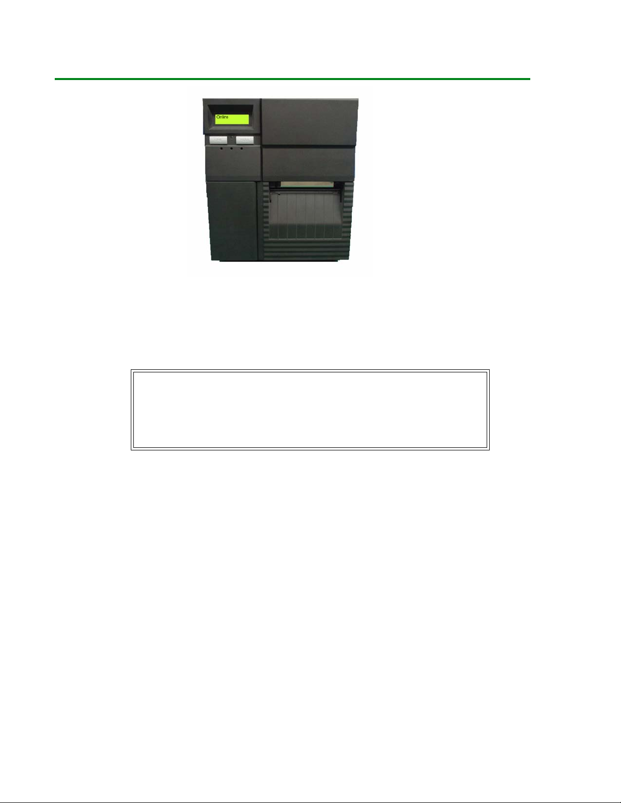
General Printer Description
The LE810DT printer comes in several configurations which can differ by
• Connection ports on the back of the printer
• Default print mode
• Internal path for print media
Note
The appearance of your printer may differ somewhat
from the illustrations in this manual, depending on the
model you purchased.
LE810DT User’s Guide 5 Introduction
Page 6

Printer Components
1 Operator Panel
2 Print Assembly
3 Platen Roller
4 Dispenser Latch
5 Print Head Latch
6 Rewinder Shaft (only present on some models)
7 External Media Slot
8 Media Holder
LE810DT User’s Guide 6 Introduction
Page 7
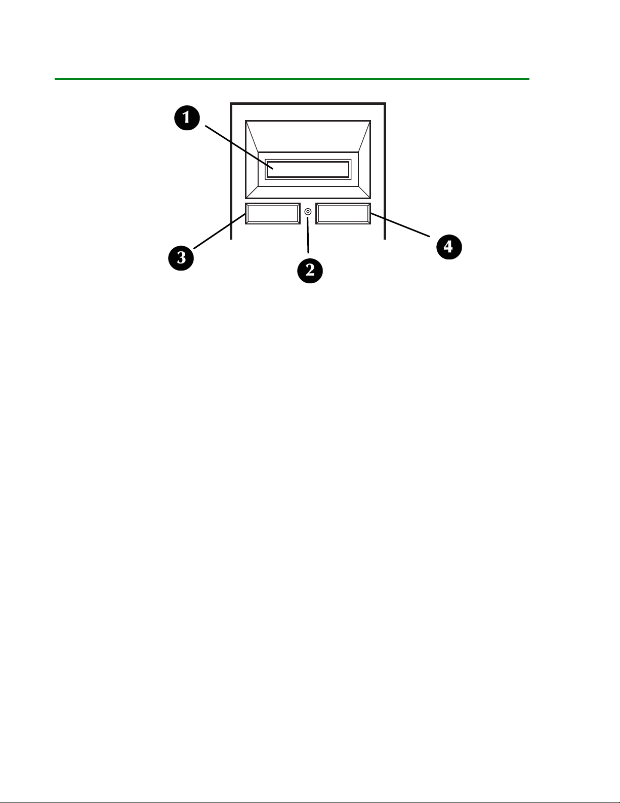
Operator Panel
1 LCD Display
2 Status LED
- Illuminates green when online and turns off when offline.
- Blinks green when receiving data or the buffer is near full.
- Illuminates or blinks red when detecting a printer error.
3 LINE button
- Press to switch back and forth between online and offline state.
- Press to scroll through menu options.
- Press to initiate other special functions as indicated later in this manual.
4 FEED button
- Press to advance the label media.
- Press to select menu options.
- Press top initiate other special functions as indicated later in this manual.
LE810DT User’s Guide 7 Introduction
Page 8
Installation
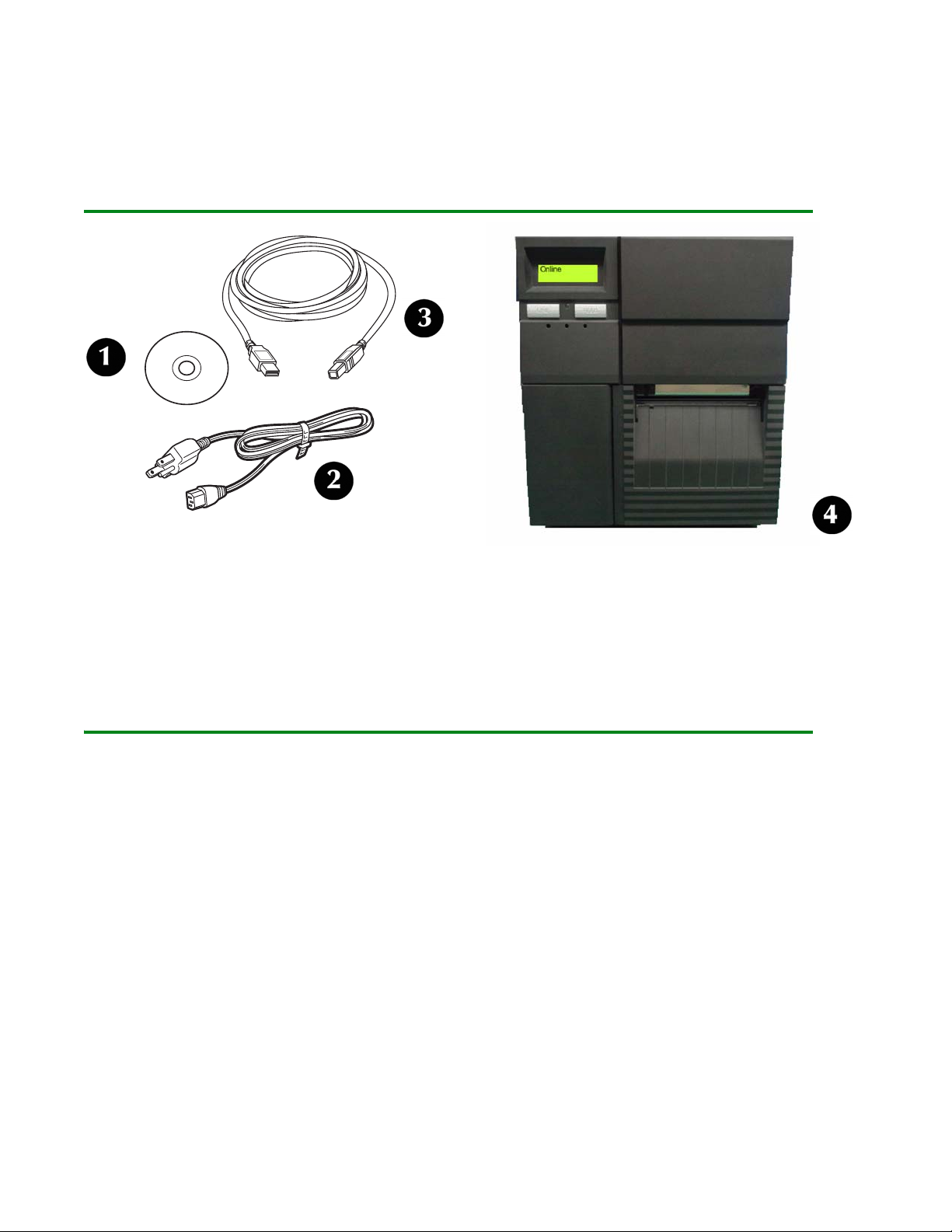
Parts Identification
1 CD-ROM
2 Power Cable
3 USB Cable (included only on models equipped with a USB port)
4 Printer (front view)
Printer Installation
Site Location
• Place the printer on a solid flat surface, away from hazardous materials.
• Make sure it is within operational distance of the host, based on interface
specifications.
LE810DT User’s Guide 8 Installation
Page 9
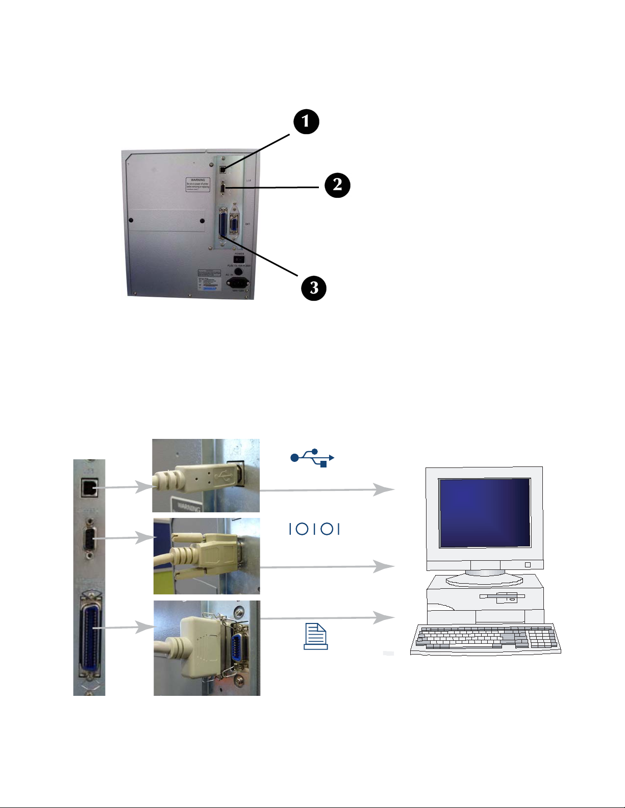
Interface Connection
USB / RS232C / IEEE Models
1. Locate the interface connection ports on the back of the printer.
1: USB
2: Serial (RS-232C)
3: IEEE Parallel
2. Connect the appropriate cable to the interface port, then connect it to the
computer.
USB
RS232C
IEEE
LE810DT User’s Guide 9 Installation
Page 10

Ethernet (LAN) Models
1. Locate the Ethernet port on the back of the printer.
2. Plug a 10/100Base T Category 5 Ethernet cable (not supplied) into the Ethernet
port on the printer and then into the computer.
USB Only Model
1. Locate the USB port on the back of the printer.
2. Plug the USB cable supplied with the printer into the USB port on the printer,
then into the USB port on the computer.
USB
LE810DT User’s Guide 10 Installation
Page 11
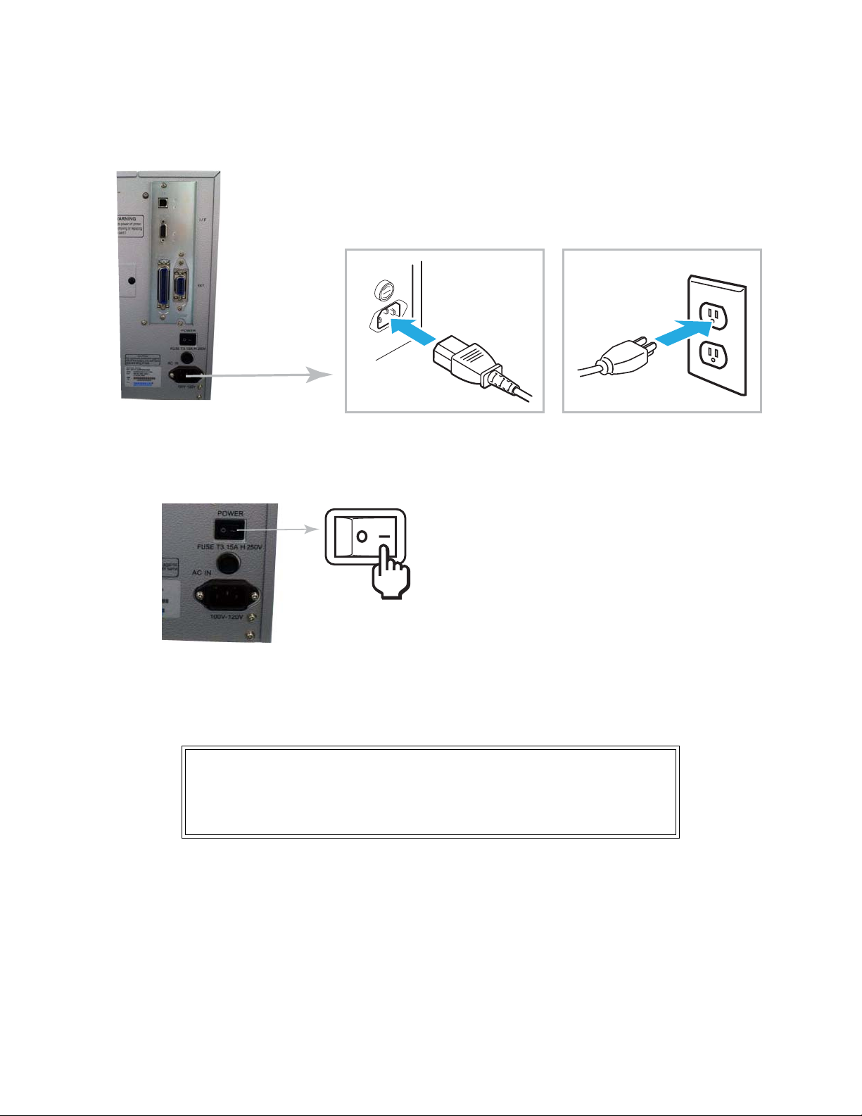
Connect to Power
1. Connect the power cable to the power socket on the back of the printer, then
connect it to a 120-volt, grounded power outlet.
2. Turn the printer on.
3. Set the interface option in the configuration menus of the operator panel. Refer
to the Configuration unit of this manual to configure the printer for host
computer interfacing.
Note
Multiple interface options may display in the printer’s
LCD menus, the desired option must be chosen.
LE810DT User’s Guide 11 Installation
Page 12

Media Selection
Caution
The media width should be equal to, or just
narrower than, the print head. Using media that
does not cover the print head will allow the
platen roller to tread on it and wear it out. The
media edge will also wear a groove in the platen
roller affecting print quality.
Both roll-type and fanfold media can be used with the printer. To use fanfold
media, you may need to remove the access plate on the back of the printer as
described under Loading Media, Fanfold Type.
LE810DT User’s Guide 12 Installation
Page 13
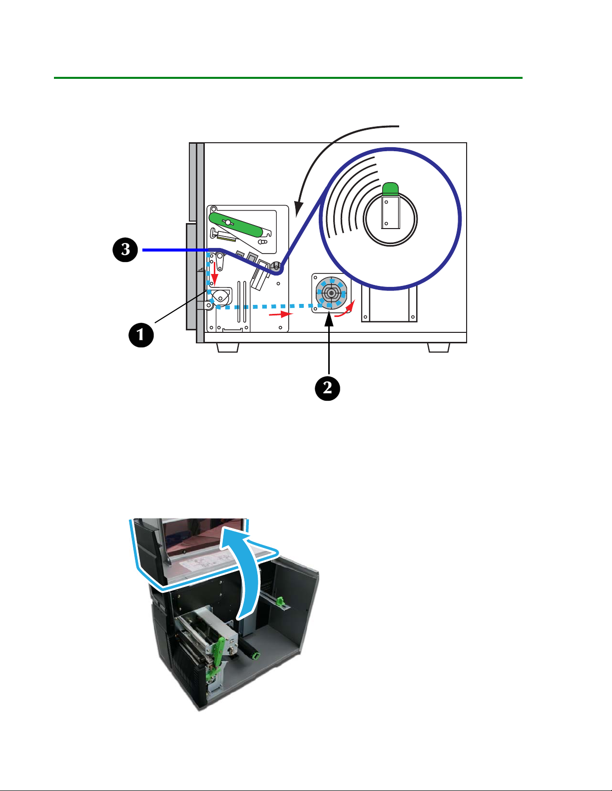
Loading Media
Roll-Type, with Liner Fed to Rewinder Shaft
With roll-type media loaded this way, the liner (1) automatically separates from the
media and is pulled back into the printer and wrapped around the rewinder shaft
(2). The self-adhesive label (3) without its liner moves out the front of the printer
for pickup and direct application. The printer will not print another label until the
printed label is removed.
1. Lift up the Top Access Cover.
LE810DT User’s Guide 13
Page 14

2. Open the printer front door: push down on the green dispenser latch (1) to
release the door, then swing it open (2).
3. Open the Print Head Assembly by rotating the Head Latch (1) counter clockwise.
LE810DT User’s Guide 14
Page 15

4. Pull the green Media Supply Guide (1) out as far as it will go, then angle the
label roll over it and push the roll back against the printer housing. Push the
Media Support Guide back in until it fits snugly against the media roll (2).
5. Locate the metal Outside Media Guide (1) under the print path and slide it
toward you as far as it will go.
LE810DT User’s Guide 15
Page 16
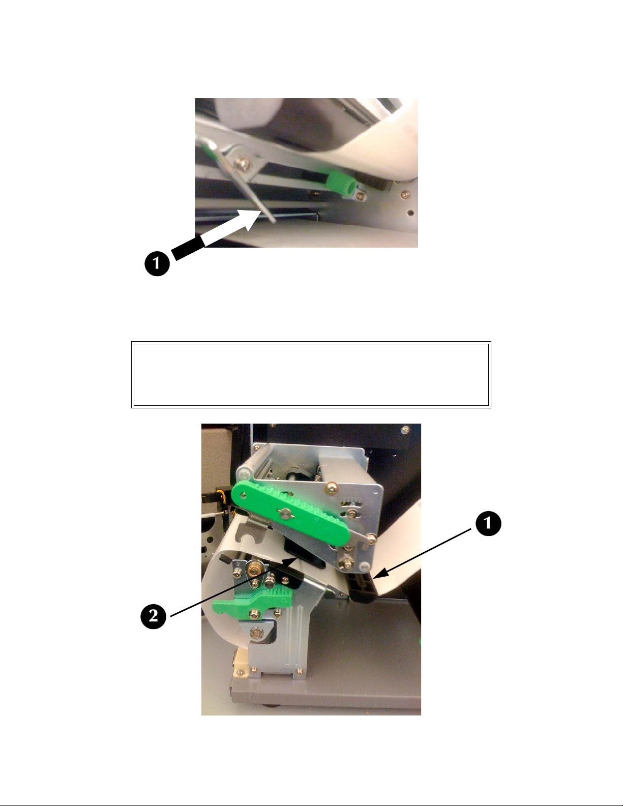
6. Push in on the bottom of the Outside Media Guide (1) to move the top out of the
way while you are loading the media.
7. Slide the media into the print path, making sure it goes under the Media
Hold-Down (1) and under the Sensor Assembly (2) Push it against the back of
the printer.
Attention!
If the media does not go under the Sensor Assembly,
the printer will not recognize that media is loaded.
LE810DT User’s Guide 16
Page 17

8. Adjust the media sensor to compensate for irregularities in the media (i.e.:
notch, tag hole, gap, perforation or markings). The proper position will be
media-dependent. To properly adjust the sensor position, loosen the green
Sensor Adjust Knob located on the bottom side of the Media Transport Assembly
and move the sensor in ¼-inch increments (or finer) until the sensor error is
cleared. After the error is cleared, retighten the Sensor Adjust Knob.
9. Pull out the bottom of the Outside Media Guide so that it is upright, then push
the guide inward until it barely contacts the outside edge of the media.
LE810DT User’s Guide 17
Page 18

10.Pull the media roll out until about 24 inches are exposed, then remove the labels
from that section. Feed the end of the liner back into the bottom of the printer,
under the Backing Drive Roller (1).
11.Pull out the green tab (1) on the front of the Take-Up Spindle (2). Notice the two
prongs (3) on the Take-Up Spindle. Pull the liner through the bottom of the
printer and pass the end under the two prongs, then use the green tab to rotate
the spindle until the liner is wrapped around it several times. When you are
done, swing the tab back into place.
LE810DT User’s Guide 18
Page 19

12.Swing the Head Latch back down to close the print head, then latch it in place.
13.Close the front door and lower the top access cover into place.
b
Attention!
These covers have interlock switches and the printer
will not operate if either is open.
LE810DT User’s Guide 19
Page 20

Roll-Type, Front Exit with Liner Attached
1. Lift up the Top Access Cover.
LE810DT User’s Guide 20
Page 21

2. Open the printer front door: push down on the green dispenser latch (1) to
release the door, then swing it open (2).
3. Open the Print Head Assembly by rotating the Head Latch (1) counter clockwise.
LE810DT User’s Guide 21
Page 22

4. Pull the green Media Supply Guide (1) out as far as it will go, then angle the
label roll over it and push the roll back against the printer housing. Push the
Media Support Guide back in until it fits snugly against the media roll (2).
5. Locate the metal Outside Media Guide (1) under the print path and slide it
toward you as far as it will go.
LE810DT User’s Guide 22
Page 23

6. Push in on the bottom of the Outside Media Guide (1) to move the top out of the
way while you are loading the media.
7. Slide the media into the print path, making sure it goes under the Media
Hold-Down (1) and under the Sensor Assembly (2) Push it against the back of
the printer.
Attention!
If the media does not go under the Sensor Assembly,
the printer will not recognize that media is loaded.
LE810DT User’s Guide 23
Page 24

8. Adjust the media sensor to compensate for irregularities in the media (i.e.:
notch, tag hole, gap, perforation or markings). The proper position will be
media-dependent. To properly adjust the sensor position, loosen the green
Sensor Adjust Knob located on the bottom side of the Media Transport Assembly
and move the sensor in ¼ inch increments (or finer) until the sensor error is
cleared. After the error is cleared, retighten the green Sensor Adjust Knob.
9. Pull out the bottom of the Outside Media Guide so that it is upright, then push
the guide inward until it barely contacts the outside edge of the media.
LE810DT User’s Guide 24
Page 25

10.Swing the Head Latch back down to close the print head, then latch it in place.
11.Close the front door and lower the top access cover into place.
b
Attention!
These covers have interlock switches and the printer
will not operate if either is open.
LE810DT User’s Guide 25
Page 26

Fanfold Type
1. Lift up the Top Access Cover.
LE810DT User’s Guide 26
Page 27

If the back plate is on your printer, perform the following step; other wise, skip to step 3.
2. Remove the back plate covering the access hole.
a. Press on the pin holders (1) inside the printer at either end of the bracket
until the pins extend from the outer housing.
b Carefully pull out the pins at either end of the cover plate and save them.
You will need the pins if you ever decide to reinstall the back plate.
c Remove the plate from the printer.
Save it with the pins: you will need them should you ever decide to reinstall
it.
LE810DT User’s Guide 27
Page 28

3. Place the stack of fanfold media behind the printer and feed the first label in
through the opening.
M
E
D
I
A
M
E
D
I
A
M
E
D
I
A
M
E
D
I
A
M
E
D
I
A
M
E
D
I
A
M
E
D
I
A
4. Locate the metal Outside Media Guide (1) under the print path and slide it
toward you as far as it will go.
LE810DT User’s Guide 28
Page 29

5. Push in on the bottom of the Outside Media Guide (1) to move the top out of the
way while you are loading the media.
6. Slide the media into the print path, making sure it goes under the Media
Hold-Down (1) and under the Sensor Assembly (2) Push it against the back of
the printer.
Attention!
If the media does not go under the Sensor Assembly,
the printer will not recognize that media is loaded.
LE810DT User’s Guide 29
Page 30

7. Adjust the media sensor to compensate for irregularities in the media (i.e.:
notch, tag hole, gap, perforation or markings). The proper position will be
media-dependent. To properly adjust the sensor position, loosen the green
Sensor Adjust Knob located on the bottom side of the Media Transport Assembly
and move the sensor in ¼ inch increments (or finer) until the sensor error is
cleared. After the error is cleared, retighten the green Sensor Adjust Knob.
8. Pull out the bottom of the Outside Media Guide so that it is upright, then push
the guide inward until it barely contacts the outside edge of the media.
LE810DT User’s Guide 30
Page 31

9. Swing the Head Latch back down to close the print head, then latch it in place.
10.Close the front door and lower the top access cover into place.
b
Attention!
These covers have interlock switches and the printer
will not operate if either is open.
LE810DT User’s Guide 31
Page 32

Operational Mode Selection
There are three modes of printer operation; Tear-off, Continuous, and Dispense.
Tear-off Mode
• For printing labels one at a time.
• The liner remains with the label as it exits the printer.
• Once the printed label has been removed from the printer, the unprinted media
will retract and position itself for printing the next label.
Continuous Mode
• For printing bulk quantities of labels.
• The liner remains with the label as it exits the printer.
• The media remains in position for printing at all times.
• A printed label is only available for removal when one to four additional labels
have been printed (quantity depends upon label size).
Dispense Mode
• For printing labels one at a time.
• The printer automatically peels the liner from the printed label as it exits the
printer.
• Once the printed label has been removed from the printer, the unprinted media
will retract and position itself for printing the next label.
LE810DT User’s Guide 32
Page 33

Printer Configuration
Basic Configuration Modes
Configuration is done using the operator panel buttons. However, many settings
may also be controlled via external software commands. In the case of conflict
between external software commands and control panel settings, the printer will
always use the last valid setting (the default is software commands).
See the Menu Definition Tables starting on page 39 for more information on the
modes below.
Normal Mode
For configuring print features that tend to change from job to job. See page 39.
POWER: ON
Scrolls
options
ONLI NE
QTY: 000000
LINE FEED
LINE + FEED
OFFLINE
QTY: 000000
LINE FEED
PRIN T DARKN ESS
12345
FEED
PRIN T SPEED
23456
LINE
PITC H OFF SET
LINE
FEED
+00MM
[Z]
Reprints
last lab el if
enabled.
Feeds
one label if
DSW3-3is
OFF.
Scrolls
options
CANC EL PRINT JOB
YES NO
LINE
NO
FEED
All
print jobs
saved
USER TEST PRINT
YES NO
LINE
NO
FEED
YES
FEED
All
print jobs
canceled
YES
FEED
TO
TEST PRINT
MENU
Scrolls
options
Selects
and
advances
LINE
LINE
FEED
LE810DT User’s Guide 33 Printer Configuration
Page 34

Advanced Mode
For making basic printer operational adjustments. Typically, once these adjustment
settings have been made, they will not require additional changes unless a new job
is downloaded.
LINE + POWER
ADVANCED MODE
Scrolls
options
Scrolls
options
Selects
and
advances
Only if
calendar is
installe d
SET CALENDAR
YES NO
LINE
Yes
FEED
CALENDAR
YY / MM/ DD HH : MM
LINE
FEED
No
FEED
Toggles
Service
Mode
Scrolls
options
Scrolls
options
Scrolls
options
Scrolls
options
Scrolls
options
FEEDLINE
DARKNESS RANGE
AB
LINE
AUTO ON LINE
YES NO
LINE
PRINT OFFSET
V: +XXXX H: +XXX
IGNORE CR/LF
YES NO
LINE
INTERFACE TYPE
IEEE RS232 USB
LINE
FEED
FEED
LINE
FEED
FEED
Selects
and
advances
Scrolls
options
Scrolls
options
Scrolls
options
Scrolls
options
Scrolls
options
DATA BIT SELECT
8BIT 7BIT
LINE
PARITY SELECT
EVEN ODD NON
LINE
STOP BIT SELECT
1BIT 2BIT
LINE
BAUD RATE SELECT
9600 19200 >>
BAUD RATE SELECT
<< 3800 S7600
LINE
PROTOCOL SELECT
RD/BSY XON/OF >>
PROTOCOL SELECT
<< BICOM3 BICOM4
LINE
FEED
FEED
FEED
FEED
FEED
IEE/USB
FEED
RS232
FEED
LE810DT User’s Guide 34 Printer Configuration
Page 35

Counters Mode
• Print Head Counter
The head counter records the length of the media that has been printed since
the print head was installed. It should be reset each time the print head is
replaced.
•Life Counter.
The life counter measures the length of media the printer as a whole has
printed. This counter would only be reset in case of circuitry replacement.
The printer’s Counter Mode allows the operator to view the accumulated
measurement and also allows the print head counter to be reset to zero.
LINE + POWER
ADVANCED MODE
Toggles
Advanced
Mode
SERVICE MODE
LINEFEED
Scrolls
options
HD
FEED
HEADCOUNTER
HEADCOUNT CLEAR
YES NO
LINE
X. X M
FEED
FEED
Toggles
Service
Mode
Toggles
Emulation
Mode
Scrolls
options
DSP
FEED
DISPENSE COUNT ER
DSP COUNT CLEAR
YES NO
LINE
X. X M
FEED LINE
COUNTERS MODE
LINE FEED
COUNTERS
HD DSP CUT LIFE
LINE
CUT COUNTER
CUT COUNT CLEAR
YES NO
FEED
LINE
CUT
FEED
FEED
LIFE
FEED
X
FEED
LIFE COUNTER
X. X M
FEEDFEED
LE810DT User’s Guide 35 Printer Configuration
Page 36

Test Print Mode
For printing a test label.
Test labels are designed to identify failures in configuration, adjustments problems,
and mechanical defects.
FEED + POWER
TEST PRINT MODE
CONFIGURATION
BARCODE
HEADCHECK
FACTORY
Scrolls
options
Scrolls
options
LINE
Conguration
Barcode
Headcheck
FEED
TEST PRINT SIZE
XXCM
LINE
PRESS FEED KEY
TO STOP PRINTING
FEED
Test
printing
begins
FEED
Test
printing
stops
Factory
FEED
PRINT SIZE
SMALL LARGE
LINE
Scrolls
options
USER TEST PRINT
YES NO
LINE
NO
FEED
YES
FEED
Scrolls
options
PRINT CONTINUE
Scrolls
options
YES NO
LINE
YES
FEED
NO
FEED
ONLINE MODE [Z]
QTY: XXXXXX
LE810DT User’s Guide 36 Printer Configuration
Page 37

Default Setting Mode
For resetting the printer to the default configuration state as received from the
factory. Use the printer’s buttons to select and enter the required options.
LINE + F EED + POWER
DEFAULT SETTING
YES NO
Scro lls
options
DEFAULT SETTING
Yes
FEED
Print er
returned to
default
settings
COMPLETED
Power printer off
and then on again
to exit.
LINE
No
FEED
No action,
no change
LE810DT User’s Guide 37 Printer Configuration
Page 38

Hex Dump Mode
The contents of the print buffer and the contents received before it may be
examined through the use of the Hex Dump Mode. Each line of the printed data is
enumerated in the first column, the second column contains the data in
hexadecimal format, and the right column contains the same data in ASCII format.
Send ~ESC+HX command
ONLINE [Z]
QTY: XXXXXX
Print er
receives
data
Print er
begins
Hex Dump
printing
Power printer o ,
to exit
LE810DT User’s Guide 38 Printer Configuration
Page 39

Menu Definition Tables
Normal Mode
Display Description
ONLINE
QTY XXXXXX
OFFLINE
QTY XXXXXX
PRINT DARKNESS
1 2 3 4 5
PRINT SPEED
2 3 4 5 6
PITCH OFFSET
+00MM
Displays the printer’s operational status. The ONLINE status is
displayed on the top line and the label quantity status is on the
bottom. The message will be changed to OFFLINE whenever the
printer is switched offline by pressing the LINE key. When a print
job is received, the quantity line will indicate the number of labels
to be printed. As the label job prints, the display status indicates
the quantity of labels remaining to be printed.
Displays the printer’s operational status. The OFFLINE status is
displayed on the top line and the label quantity status is on the
bottom. The message will be changed to ONLINE whenever the
printer is switched online by pressing the LINE key.
Permits the adjustment of print density. Higher print density
equates to darker pint images.
Permits the printer’s printing speed to be established based on
inches per second (IPS).
The label pitch is the distance from the leading edge (the edge that
comes out of the printer first) of a label and the leading edge of the
next label. Once the position has been set, it can be fine adjusted
using the PITCH potentiometer.
Positive (+) digit settings moves the leading edge forward and
away from the print head while a negative (-) setting moves the
label’s leading edge incrementally back into the mechanism.
CANCEL PRINT JOB
YES NO
USER TEST PRINT
YES NO
LE810DT User’s Guide 39 Printer Configuration
Print data that has previously been received, can be cleared. If YES
is selected, the print data will be deleted and then the printer will
go offline. If the NO option is selected, the printer will go offline
without deleting data in buffer.
Provides the specific sequence of events required by the operator,
the printer, and the printer’s software for a test label to be printed.
Select YES to enter User Test Print menu while select NO will
advance to Online mode.
Page 40

Advanced Mode
Display Description
ADVANCED MODE
DARKNESS RANGE
A B
AUTO ONLINE
YES NO
PRINT OFFSET
V: +XXXX H: +XXX
IGNORE CR/LF
YES NO
Is the first menu screen of the Advanced Mode. The Advanced Mode is
provided to make basic printer operational adjustments. Typically,
once these adjustments or settings have been made, they will not
require additional address unless a new job is downloaded.
Allows the darkness (print density) selection of the printed image.
Has two selection options.
The printer can be set to automatically go into the online mode when
powered on. Otherwise, theprinter starts in the offline state and must
be manually placed online before it is ready to print.
Print offset refers to the vertical and horizontal shifting of the entire
print area relative to the label and the print start position. The
movement is incremental by dots in the positive (+) or negative (-)
direction. Positive and negative vertical adjustment is toward and
away from the print head respectively. Positive and negative
horizontal adjustment is to the left and right of the reference point
respectively.
Determines whether the print data code requires deletion.
Hexadecimal graphic data will not be deleted. Select YES to delete all
carriage return (CR) and line feed (LF) commands in the data stream
- including graphics and 2D barcodes.
SET CALENDAR
YES NO
CALENDAR
00 / 00 / 00 00:00
INTERFACE TYPE
IEEE RE232 USB
The calendar is an optional feature that allows the date and time to
be manually set using the operator panel or through command codes.
This screen will not be displayed if the calendar chip (real-time clock)
is not installed.
This menu allows the operator to choose if the calendar settings are
to be altered.
• This menu screen allows the calendar settings to be altered. The
calendar is divided into five sets of two digits. The first two allows
for the year to be set, followed by the month, the day, the hour,
then the minute.
• This menu will display only when the standard Plug-in 3-in-1 combo
interface module is installed. Select the type of interface according
to the connection to the host. Either IEEE, RS232 or USB interface
can be selected.
• If the optional single interface board (LAN or USB) is installed, this
menu will not be displayed.
LE810DT User’s Guide 40 Printer Configuration
Page 41

Counters Mode
Display Description
ADVANCED MODE
SERVICE MODE
COUNTERS MODE
COUNTERS
HD LIFE
HEAD COUNTER
XXXM
LIFE COUNTER
XXXM
HEAD COUNTER CLEAR
YES NO
First transitional menu screen to access the Counters Mode.
Second transitional menu screen to access the Counters Mode.
Is the first menu screen of the Counters Mode. The Counters
Mode allows the printers various internal counters to be reset to
zero or to view count in meters printed thus far.
Allows the selection of which counter to be viewed to reset.
HD: Head counter
LIFE: Life counter
Is an informational screen that provides the printed length of
media using the existing print head.
The head counter must be reset each time the print head is
replaced.
Is an informational screen that provides the printed the length of
media since printer setup.
Resets the print head counter to zero.
LE810DT User’s Guide 41 Printer Configuration
Page 42

Test Print Mode
Display Description
TEST PRINT MODE
CONFIGURATION
BARCODE
HEADCHECK
FACTORY
TEST PRINT SIZE
XXCM
PRINT SIZE
SMALL LARGE
PRESS FEED KEY
TO STOP PRINTING
PRINT CONTINUE
YES NO
Is the initial screen of the Test Print Mode.
• CONFIGURATION: The printer’s configuration settings.
• BARCODE: The printer’s installed barcodes.
• HEAD CHECK: A pattern to check print head elements.
• FACTORY: A factory test label will be printed.
This menu screen only appears if CONFIGURATION, BARCODE, or
HEAD CHECK was chosen in the previous menu. The increments of
measure is 1cm.
For factory test prints, this screen appears instead of the previous
screen for setting print size.
Large (10cm) and small (4cm) are the only two options.
Is a directional screen prompting action on how to terminate print
activity. Press FEED to stop printing and press again to resume
printing.
A confirmation screen to stop test printing or to continue the label
test printing.
If YES is selected, the printer will goes back to TEST PRINT MODE
selection menu. If NO is selected, the test print mode will stop and
proceed to Online mode.
USER TEST PRINT
YES NO
ONLINE MODE (Z)
QTY: XXXXXX
Provides the specific sequence of events required by the operator, the
printer, and the printer’s software for a test label to be printed.
Select YES to enter User Test Print menu while select NO will advance
to Online mode.
Displays the printer’s operational status. The ONLINE status is
displayed on the top line and the label quantity status is on the
bottom.
Ready for print job.
LE810DT User’s Guide 42 Printer Configuration
Page 43

Default Setting Mode
Display Description
DEFAULT SETTING
YES NO
DEFAULT SETTING
COMPLETED
Is the first menu screen of the printer’s Default Setting Mode. The
Default Setting Mode allows the printer to be reset to the
programmed condition as received from the factory.
The selection of YES confirms the operator wants to proceed and the
selection of NO allows for exit without default reset. If YES is
selected, resetting will immediately begin.
Reboot the printer to return to normal operation.
Is an informational screen only indicating that reset activity is
complete.
Hex Dump Mode
Display Description
ONLINE (Z)
QTY: XXXXXX
Displays to indicate the printer is online and waiting to print HEX
interpretation of data received by the print buffer.
LE810DT User’s Guide 43 Printer Configuration
Page 44

Troubleshooting
Test Label Printing
The test label is designed to assist in the identification of print problems. The actual
content of the test label depends on the type of test label printed.
To print a test label:
1. To enter the Test Print mode, turn off the printer, then press and hold the FEED
button while turning the printer on.
TEST PRINT MODE appears on the display.
2. Press the LINE button to scroll to your choice of CONFIGURATION, BARCODE or
HEADCHECK, then press FEED to select it.
The display shows the current test print size.
3. To change the size, use the LINE button to scroll through the various choices.
4. Once the appropriate size is selected, press FEED to start printing the test label.
5. When the label has finished printing, press FEED to stop the test.
6. To exit the Test Print mode, turn the printer off, then on again.
LE810DT User’s Guide 44 Troubleshooting
Page 45

Sample Test Print Label
Note
The only print problem that the following sample test
label does not display is fading of print image from one
side of the label to the other. This type of fading is the
result of improper print head balance.
D S W 3D S W 2D S W 1
N O N E
1Compare this scale on each side to ensure the print is evenly spaced
horizontally.
2 Visually inspect these rows for voids indicating defective elements.
3 Line sharpness is determined by print speed and darkness.
4 Compare this scale on either side to ensure the print is evenly spaced vertically.
LE810DT User’s Guide 45 Troubleshooting
Page 46

Maintenance
Cleaning the Printer
Warning!
Disconnect the power cord and allow the printer
to cool to room temperature before cleaning.
Be careful when cleaning to prevent personal
injury.
Cleaning of the printer is a necessary maintenance activity to ensure print quality
and longer printer life. There are two basic types of cleaning involved; the removal
of loose debris and the removal of residue.
Removing Debris
Use a soft cloth and/or a pneumatic blower to remove debris from the printer. This
process should be performed prior to the removal of residue.
Caution
If you are using a pneumatic blower to remove
debris from the printer, be careful to stay away
from the print head to avoid damaging it.
LE810DT User’s Guide 46 Maintenance
Page 47

Cleaning the Print Head and Platen
Attention!
The print head should be cleaned after every other
label roll is loaded.
1. Turn the printer off and remove the power cable.
2. Open the Top Access Cover.
LE810DT User’s Guide 47 Maintenance
Page 48

3. Rotate the green Head Latch counter clockwise to open the print head.
4. Remove any print media from the print head.
5. The print head faces downward along the front edge of the print head assembly.
6. Apply some isopropyl alcohol (available at most pharmacies) to a cotton swab,
then gently run the swab across the full width of the print head.
7. Check the swab for any dark coloring or adhesive. If either is present, run a new
swab over the print head. Repeat until no residue is found on the swab.
8. Next, clean the platen roller by running a fresh cotton swab (with alcohol on it)
along the platen. Be sure to rotate the platen to clean all of its surface.
9. Allow the roller to dry, then reload the print media and close the top cover.
Cleaning the Printer Housing
Use a soft lint-free cloth dampened with a bit of water to wipe the printer housing
clean.
LE810DT User’s Guide 48 Maintenance
Page 49

Specifications
Physical Characteristics
Width 10.7 Inches (271 mm)
Height 12.7 Inches (322 mm)
Depth 16.9 Inches (428 mm)
Weight 32.6 Pounds (14.8 Kg)
Power
Input Voltage 100-120 Volts AC +/- 10%, 50/60 Hertz +/-5%
Power Consumption
Peak Time : 190VA 130W
Idle : 24VA 16W
Environmental
Operating Temperature 41 to 104°F (5° to 40°C)
Storage Temperature 23 to 140°F (-5° to 60°C)
Storage Humidity 30 to 90% RH Non-Condensing
Operating Humidity 30 to 80% RH Non-Condensing
Processing
CPU 32 Bit RISC
Flash ROM 2 Megabytes
Receive Buffer 2.95 Megabytes maximum, 2 Megabytes near full
LE810DT User’s Guide 49 Specifications
Page 50

Interfaces
Model Interface(s)
Combo Interface Board:
LE810DT- SER/PAR/USB
LE810DT- ETHERNET Ethernet: 10/100 Base-T
LE810 DT – PAR Parallel: IEEE1284 Enhanced Parallel Port
LE810 DT – SER Serial: RS232C (9600 to 57,600 bps)
LE810 DT – USB USB: Universal Serial Bus (USB Full Speed)
• Serial: RS232C (9600 to 57,600 bps)
• Parallel: IEEE1284 Enhanced Parallel Port
• USB: Universal Serial Bus (USB Full Speed)
Print Specifications
Method Direct Thermal
Maximum Speed (selectable) 2, 3, 4, 5, 6 Inches Per Second (50.8 - 152.4 mm)
Print Module (dot size) .0049 Inches (.125 mm)
Resolution 203 Dots Per Inch (8 dpmm)
Maximum Print Width 4.09 Inches (104 mm)
Maximum Print Length 15.75 Inches (400 mm)
Sensing Specifications
Gap Adjustable
Reflective I-Mark Adjustable
Media Out Constant
Cover Open Constant
LE810DT User’s Guide 50 Specifications
Page 51

Media
Width
• Media Width: 0.866 to 5.04 Inches (22-128 mm)
• Media Width with Backing Paper: 0.984 to 5.16 Inches (25131 mm)
Length
Length (Tear-Off)
Typ e
Thickness 0.003 to 0.010 inches (0.08-0.26 mm)
Roll Diameter Maximum: 8.6 inches (218 mm)
Core Diameter 3.0 Inches (76.2 mm)
Wind Direction Face Inward
Fan-Fold Height Maximum: 3.94 Inches (100 mm)
• Media Length: 15.63 Inches (397 mm)
• Media Length with Backing Paper: 15.75 Inches (400 mm)
• Media Length: 0.669 to 7.01 Inches (17-178 mm)
• Media Length with Backing Paper: 0.787 to 7.13 Inches (20181 mm)
• Roll or Fan-Fold
•I-Mark or Gap
• Direct Thermal
Commands
• ZEBRA emulation and ZPL command
Standard
Non-Standard N/A
LE810DT User’s Guide 51 Specifications
• SATO Barcode Printer Language (SBPL)
• Intelligent Command
Page 52

Character Font Capabilities
TTF fonts
0 15 dots H x 12 dots W
Bitmap fonts
A 9 dots H x 5 dots W
B 11 dots H x 17 dots W
C 18 dots H x 10 dots W
D 18 dots H x 10 dots W
E 28 dots H x 15 dots W
F 26 dots H x 13 dots W
G 60 dots H x 40 dots W
H 21 dots H x 13 dots W
P 20 dots H x 18 dots W
Q 28 dots H x 24 dots W
R 35 dots H x 31 dots W
S 40 dots H x 35 dots W
T 48 dots H x 42 dots W
U 59 dots H x 53 dots W
V 80 dots H x 71 dots W
Downloadable Fonts
N/A
Character Control
Expansion up to 12 x in either the X or Y coordinates.
Character Pitch Control
Line Space Control
Journal Print Facility
0, 90, 180, and 270 Degree Rotation
LE810DT User’s Guide 52 Specifications
Page 53

Bar Code Capabilities
Bar Code Capabilities
• UPC A/E
• JAN 8/13
•EAN 8/13
• Code 39
• Code 93
• Code 128
• Interleaved 2 of 5
Linear Bar Codes
• Industrial 2 of 5
•Matrix 2 of 5
• Bookland
•NW-7
•MSI
•POSTNET
• UCC/EAN 128
• NW-7 (Codabar)
•QR Code
• Data Matrix
Two Dimensional
Ratios 1:2, 1:3, 2:5, User definable bar widths
Bar Height 4 to 999 dots, User programmable
Rotation 0, 90, 180, and 270 Degrees
Sequential Numbering Sequential numbering of both numerics and bar codes
Expansion Ratio of
Character
Graphics Full dot addressable graphics, BMP or PCX formats
Form Overlay Form overlay for high-speed editing of complex formats
•Maxi Code
•PDF417
•Synthetic Symbol
• Height: 1 to 12 times
• Width: 1 to 12 times
LE810DT User’s Guide 53 Specifications
 Loading...