

Page 1

LD670
Page 2
Every effort has been made to ensure that the information in this document is complete, accurate, and
up-to-date. The manufacturer assumes no responsibility for the results of errors beyond its control. The
manufacturer also cannot guarantee that changes in software and equipment made by other
manufacturers and referred to in this manual will not affect the applicability of the information in it.
Mention of software products manufactured by other companies does not necessarily constitute
endorsement by the manufacturer.
While all reasonable efforts have been made to make this document as accurate and helpful as possible,
we make no warranty of any kind, expressed or implied, as to the accuracy or completeness of the
information contained herein.
All rights are reserved by Oki Data Corporation. Unauthorized copying, transferring, translating, or
related actions are prohibited. You must obtain written permission from Oki Data Corporation before
doing any of the above.
© 2011 Oki Data Corporation
OKI is a registered trademark of Oki Electric Industry Co., Ltd.
Energy Star is a trademark of the United States Environmental Protection Agency.
Microsoft, Windows, Windows Server and Windows Vista are registered trademarks of Microsoft
Corporation.
Apple, Macintosh, Rosetta, Mac and Mac OS are registered trademarks of Apple Inc.
Other product names and brand names are registered trademarks or trademarks of their proprietors.
As an Energy Star Program Participant, the manufacturer has determined that this product
meets the Energy Star guidelines for energy efficiency.
This product complies with the requirements of the Council Directives 2014/30/EU (EMC) and
2014/35/EU (LVD), 2014/53/EU (RED) and 2011/65/EU(RoHS) as amended where
applicable, on the approximation of the laws of the member states relating to Electromagnetic
Compatibility, Low Voltage, Radio & Telecommunications Terminal Equipment, Energy
related Products and Restriction on the use of certain Hazardous Substances in electrical
and electronic equipment.
The following cables were used to evaluate this product to achieve EMC directive
2014/30/EU compliance and configurations other than this may affect that compliance.
&$%/(7<3( &25(CORE
CABLE TYPE
Power 2.0
USB 5.0
Serial (25pin)
LAN
Drawer 1.8
This is a class A product as defined in EN55022. In a domestic environment
this product may cause radio interference, in which case the user may be required to
take adequate measures.
LENGTH
(METRE)
15.0
10.0
CORE SHIELD
88
89
89
88
88
Page 3

M
ANUFACTURER
Oki Data Corporation,
4-11-22 Shibaura, Minato-ku,
Tokyo 108-8551,
Japan
For all sales, support and general enquiries contact your local distributor.
I
MPORTER TO THE
OKI Europe Limited (trading as OKI Printing Solutions)
Blays House
Wick Road
Egham
Surrey, TW20 0HJ
United Kingdom
For all sales, support and general enquiries contact your local distributor.
E
NVIRONMENTAL INFORMATION
EU/A
UTHORISED REPRESENTATIVE
Page 4
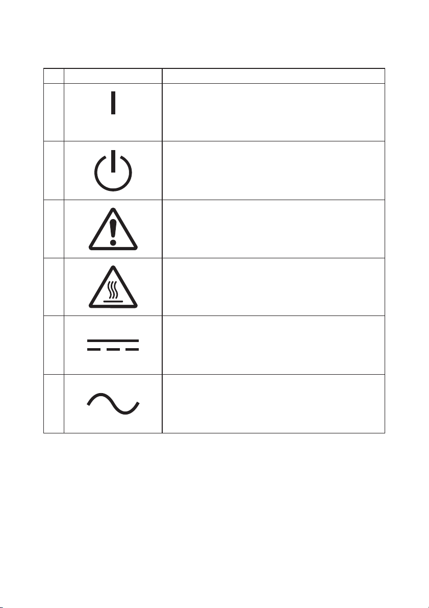
Description of Safety symbols displayed on the equipment
No. Symbol Description
1
"ON" (power)
To indicate connection to the mains, at least for
mains switches or their positions.
2
3
4
5
6
Stand-by
To identify the switch or switch position by means of
which part of the equipment is switched on in order
to bring it into the stand-by condition.
General warning/caution
To identify a general warning/caution.
Caution, hot surface
To indicate that the marked item can be hot and
should not be touched without taking care.
Direct current
To indicate on the rating plate that the equipment is
suitable for direct current only; to identify relevant
terminals.
Alternating current
To indicate on the rating plate that the equipment
is suitable for alternating current only; to identify
relevant terminals.
Page 5

Notes on Use
Notes on printing and the paper used
(1) Printing at a high rate might result in unclear printing. If this problem occurs,
adjust the printing rate. Alternatively, adjust the print speed and print density so
that there are no blurs.
(See Examples (1) and (2) in Section 10-2, "Setting Up the Printer.")
(2) Printing characters from a non-standard character set e.g. in a thin serif font will
result in the characters appearing very faint. Use a bold sans serif font.
(3) For quality printing that is free from uneven spacing and condensed or elongated
printing after paper is cut or printing is paused, resume printing following a paper
feed of at least 1 mm (8 dots).
(4) If the data transfer rate is too low, serial printing may result in uneven print
density (vertical white marks may appear on printouts) because of repeated
printing and pausing. If priority is placed on print quality, use batch printing
mode.
(See Example (8) in Section 10-2, "Setting Up the Printer.")
(5) The printer shipped from the factory is preset to the darkest print density
(130%). If this setting is inappropriate, specify a lighter print density.
(See Example (1) in Section 10-2, "Setting Up the Printer.")
(6) If roll paper with an outside core diameter of other than 32 mm is used, the
paper-near-end detection accuracy deteriorates.
If roll paper with an outside core diameter of less than 32 mm is used, a transport
error may occur when the cutter cuts the paper in full cutting mode and reaches
the core.
(7) Since the difference in hue between red and black or blue and black may not be
noticeable when two-color thermal paper is used, be sure to confirm in advance the
color of the printed characters.
(8) When roll paper with a width of 83 mm is used, characters that are too close to the
(left or right) edge of the paper may not be printed because of inaccuracies in
tracking. Be sure to set a margin of sufficient width.
(9) Do not switch from narrow paper to wide paper (e.g., from paper that is 58 mm
wide to paper that is 80 mm wide) during operation. When narrow paper is used,
the thermal head area where there is no paper comes in direct contact with the
platen roller, and the resulting wear on the head may lead to a deterioration in
print quality. Similarly, if the paper width is changed, the cutter blade will cut at
a location that has no paper, and the resulting wear on the blade may lead to
improper cuts. To switch from narrow paper to wide paper, exchange the thermal
head and the cutter blade.
3
Page 6

(10) If label paper is used, adhesive matter adhering to the cutter blade, thermal head,
paper transport, or paper holder may cause a cutting error, print error, or paper
transport error. Remove adhesive matter periodically (typically on a monthly
basis).
(11) If paper is left inserted in the printer for a long time, the paper may become
deformed and result in thin (faint) printed characters. Before starting printing
in such cases, feed the paper by 20 to 30 mm.
(12) If the type of paper used is other than the recommended ones, the print quality
and thermal head life are not guaranteed. In particular, if the type of thermal
paper contains Na+, K+, or Cl-, the thermal head life may be significantly
shortened.
(13) When using full-sheet label paper, note that the paper may adhere to the head
and cause noise if the top margin is less than 3 mm. You should therefore set
the top margin to 3 mm or a greater value when printing on this type of paper.
4
Page 7

Notes on using the cutter
(1) Note also that the paper length used per transaction must be at least
15mm.
(2) The maximum number of successive cuts by the cutter is 30 cuts per
minute (at least two seconds per cut). Using the cutter at a higher rate may
cause a failure.
(3) Do not pull the paper during cutting. Doing so may cause a paper jam or
another problem.
(4) Each time that 30 sheets of paper are printed, the paper must be removed.
Otherwise, the printed paper remains in the automatic cutter section and may
cause a cutting error.
Notes on printing of barcodes and two-dimensional codes
(1) Barcodes that are rotated 90 degrees or aligned vertically when printed may
not be readable. Verify the readability in advance.
(2) Printouts on label paper or thick paper may contain blurs, depending on
humidity and other environmental conditions. Adjust the print speed and
print density appropriate for the type of paper used, and verify the
readability in advance.
(See Examples (1) and (2) in Section 10-2, "Setting Up the Printer.")
(3) The recognition ratio of two-dimensional codes (QR codes, PDF417,
DataMatrix, MaxiCode and RSS) varies depending on various factors,
including the module width, print density, ambient temperature, thermal
roll paper type, and reader performance. Adjust the print speed and print
density appropriate to printing two-dimensional codes, and verify the
readability in advance.
(See Examples (1) and (2) in Section 10-2, "Setting Up the Printer.")
(4) The paper transport accuracy may be negatively affected by printing a
barcode in the Upper margin at the beginning of paper transport or in the
Lower margin at the end of paper transport. Verify the readability before
starting printing.
5
Page 8

Notes on using the printer through the USB interface
(1) The printer must be connected directly to the host computer.
(2) Before starting printing, turn on the power to the printer.
(3) If a printer error occurs during printing, recover the printer from the
error, and then retry printing.
(4) The host computer should not be set to any of the following modes: standby,
sleep, suspend, and pause.
If the host computer or printer does not work normally after the host
computer returns to normal operation mode from one of the above modes,
disconnect the USB cable once and then reconnect it, or turn off the printer
power switch once and then turn on the switch again. If the host computer
or printer cannot be restored to normal operation after the cable is
reconnected or power switch is turned on again, restart the host computer.
(5) The USB hub function cannot be used when the power to the printer is off.
(6) If a peripheral device connected to the USB hub is not recognized, perform
one of the following operations:
- Disconnect the USB cable from the peripheral device once, and then
reconnect it.
- Connect the peripheral device to the other port of the USB hub.
(7) The operation of connected USB devices is not guaranteed. Before using a
USB device, verify its operation yourself.
Note : Do not turn off the power to the printer during printing.
If you inadvertently turn off the power to the printer during printing and
the printer then fails to work normally, restart the host computer.
6
Page 9

Note on installation
(1) The printer must be used indoors. If used outdoors, the printer may fail
because of dust.
Note on the modular connector
(1) This product uses a modular connector as a dedicated connector for the cash
drawer or customer display terminal. The connector must not be connected
with a connector that leads to a public switched line or other such
destination.
Note on using the printer in special mode
(1) If a large diameter roll is used, paper may fold or unusual noises may be
heard. To prevent these problems, use a roll with a small diameter (50mm
or less). If a Windows PC is used as the host system, a utility program can be
used to make settings.
Windows® is a registered trademark of Microsoft Corporation in the United
States and/or other countries.
7
Page 10

TABLE OF CONTENTS
1. Appearance and Names of Components ·········································· 11
Appended goods·········································································· 12
2. AC Adapter ················································································ 13
2-1. AC adapter ·········································································· 13
3. Paper Specifications ···································································· 14
3-1. Paper Width········································································· 14
3-2. Paper Thickness ··································································· 14
3-3. Forms of Paper ····································································· 14
3-4. Paper Types ········································································· 16
3-4-1. Requirements for full-sheet label paper ··························· 18
3-4-2. Conditions for using black mark paper ···························· 19
3-4-3. Conditions for using die-cut label paper··························· 20
3-5. Recommended Thermal Paper················································· 21
4. Preparations ·············································································· 23
4-1. Connecting Interface Cable····················································· 23
4-2. Connecting the drawer kick cable ············································ 26
4-3. Connecting the AC Adapter ···················································· 27
4-4. Disconnecting the AC Adapter ················································ 29
4-5. Turning on the Power ···························································· 30
5. Inserting Paper for Printing·························································· 31
5-1. Opening the Top Cover ·························································· 31
5-2. Setting the Paper Width························································· 32
5-2-1. Mounting separator A··················································· 33
5-2-2. Removing separators A and B ········································ 34
5-2-3. Attaching separators A and B ········································ 36
5-3. Loading Paper ······································································ 38
5-3-1. Loading roll paper························································ 38
5-3-2. Loading fanfold paper··················································· 40
5-4. Setting the Paper Guide························································· 43
5-5. Closing the Top Cover···························································· 44
6. Setting Up the Printer ································································· 45
6-1. Paper Information Setting Using the Driver······························ 47
6-1-1. Paper layout································································ 48
6-1-2. Custom paper ······························································ 49
6-1-3. Printing from an application ·········································· 53
6-2. Paper information setting using the utility································ 54
6-2-1. Paper layout································································ 54
8
Page 11

6-2-2. Setting detailed paper layout information ························ 55
6-3. Setting Paper Information Using the Printer····························· 58
6-3-1. Automatic layout detection ············································ 58
6-3-2. Setting the Paper Width················································ 59
6-3-3. Automatic layout detection ············································ 61
6-4. Replacing paper ···································································· 64
6-5. Paper Layout Errors······························································ 65
6-6. Adjusting Sensors ································································· 66
6-7. Print Density Setting····························································· 67
6-8. Print Speed Setting ······························································· 68
6-9. Cutting Position Correction ···················································· 69
6-10. Other Settings ···································································· 70
6-11. Initializing the Printer Setup Information······························· 70
7. Control Panel ············································································· 71
7-1. Control Panel ······································································· 71
7-2. Error Indications ·································································· 73
8. Preventing and Clearing Paper Jams ············································· 75
8-1. Preventing Paper Jams·························································· 75
8-2. Clearing a Paper Jam ···························································· 75
9. Troubleshooting ·········································································· 76
9-1. Power-on Problems and Errors················································ 76
9-2. Cutter-related Problems························································· 76
9-3. Printing-related Problems ······················································ 77
10. Special Modes ··········································································· 78
10-1. Test Printing ······································································ 78
10-2. Setting Up the Printer ························································· 80
Example (1): Changing the Print Density ································· 81
Example (2): Changing the Max Speed····································· 89
Example (3): Changing the Print Color····································· 97
Example (4) Changing the Feed at Power On ···························104
Example (5) Initializing the printer settings ····························112
Example (6) Changing the PNE Detect····································116
Example (7) Changing the Paper Width ··································125
Example (8) Changing the Batch(OTHER IF)···························133
10-3. Setup Items·······································································142
10-4. Sensor Adjustment ·····························································151
10-4-1. Sensor adjustment mode·············································151
10-4-2. Black mark (BM) sensor adjustment·····························156
10-4-3. Adjusting the label sensor···········································158
10-4-4. Paper-near-end (PNE) sensor adjustment······················160
10-4-5. Paper end (PE) sensor adjustment ·······························162
9
Page 12

10-5. Data Analysis ····································································165
10-6. Sample Print ·····································································169
11. Regular Cleaning ·····································································174
11-1. Cleaning the Paper Holder and Paper Transport·····················174
11-2. Cleaning the Platen Roller···················································175
11-3. Cleaning the Thermal Head ·················································179
11-4. Cleaning the Cutter Blade and Frame ···································180
12. Interface ·················································································188
12-1. LAN Interface····································································188
12-2. Dual Interface····································································190
12-3. Drawer Kick Connector ·······················································191
12-4. Specifications of Power Supply ·············································194
13. Specifications···········································································195
13-1. General Specifications·························································195
13-2. Cutter Specifications···························································199
13-3. Paper Supply Specifications ·················································200
13-4. Interface Specifications ·······················································201
13-5. Environment Specifications··················································202
13-6. Specifications of Reliability ··················································203
14. Roll Paper Unit ········································································204
14-1. Outline ·············································································204
14-2. Nomenclature ····································································204
14-3. Paper Specifications····························································206
14-4. Roll Paper Feed Specifications··············································207
14-5. Roll Paper Unit Installation Procedure ··································208
14-6. Method of setting PNE sensor ··············································213
14-7. Method of setting guide plate ···············································214
14-8. Setting the Roll Paper ·························································215
14-9. Roll Paper Unit Appearance·················································220
10
Page 13
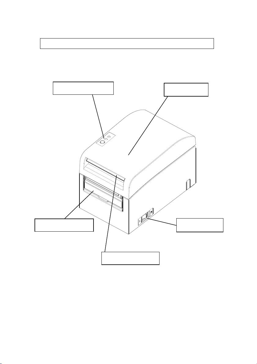
1. Appearance and Names of Components
Control panel
This panel
contains status
lamps and
operating
switches.
Top cover
Open and close this
cover to replace
forms.
Paper guide
Open the paper guide
when the expected
print length is longer
than 50 mm.
Power switch
This switch turns the
printer power on and off.
Release lever
Pull up the release lever to
open the top cover.
11
Page 14
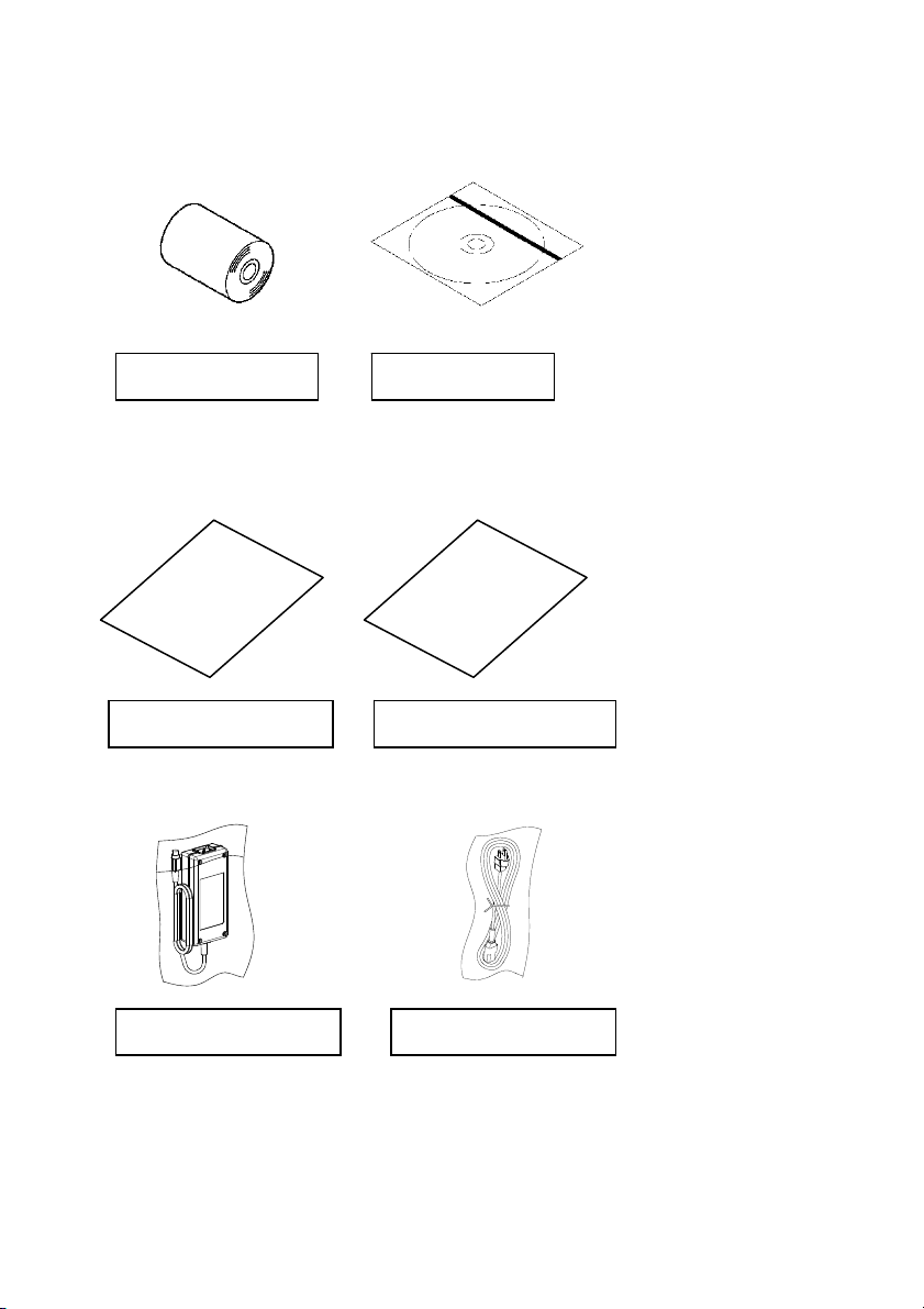
Appended goods
Thermal paper CD
MANUAL
PRINTER DRIVER
UTILITY SOFT
Instruction sheet Safety warranty sheet
AC adapter Power cable
12
Page 15

2. AC Adapter
2-1. AC adapter
Only use the AC adapter specified below.
Model name: KA02951-0120
Input: 100 to 240V AC, 50/60HzOutput: DC24V±5%, 1.5A
Caution: Only use authorized AC adapters.
Caution: Do not use the bundled AC adapter and Power cable for any
electrical equipment other than this printer.
13
Page 16

3. Paper Specifications
3-1. Paper Width
(1) Paper width of 83 mm: 83
0
mm; paper width of 80 mm: 80
-1.0
(2) Paper width within a range of 70 to 25.4 mm (by units of 1 mm)
: 70 to 25.4
0
mm
-1.0
Note: Paper with a width within a range of 71 to 79 mm cannot be used.
3-2. Paper Thickness
: 75 to 150 m
3-3. Forms of Paper
(1) Roll paper
- Outside diameter: 1020.5 mm or less
With the large-diameter roll paper unit (option) attached, the printer can use
a roll with an outside diameter of up to 200 mm.
- Core dimension: Inside diameter of 1 inch
(inside diameter: 25.40.5 mm; outside diameter: 320.5 mm)
- Printed surface: Outside of the roll
- Treatment of end of paper:The roll paper must not be glued to the core.
The end of the paper must also not be folded back.
Note: Do not use rolls that have rough sides or sides from which pieces of paper
extrude. Using such rolls could cause a printer failure.
0
mm
-1.0
14
Page 17

(2) Fanfold paper
- Maximum stack height: 180 mm or less
- Fold length: 76.2 to 203.2 0.5 mm (3 to 8 inches)
- Perforation specifications: 3 (cuts):1 (tie)
15
Page 18

3-4. Paper Types
The printer supports the following paper types:
a. Plain paper (including full-sheet label paper)
b. Black mark paper
c. Die-cut label paper (including die-cut label paper with black marks)
When using black mark or die-cut paper, the printer can move the paper to the
start position, cutting position, peeling-off position, or tear-off position according
to the paper layout settings.
To use this function, provide the printer with paper layout information,
including the paper type and size, before printing. Use of the printer without
these settings may result in a paper layout error or unexpected printouts.
Therefore, set the paper layout when you:
(1) use label paper for the first time,
(2) change the paper type (plain paper, black mark paper, or die-cut label
paper),
(3) change the paper size, or
(4) switch to die-cut label paper of the same size as the current paper but with a
different base color or other specification.
You can set the paper layout automatically or manually. For details, see Chapter
6, "Setting Up the Printer."
16
Page 19

Note: Die-cut label paper is a type of label paper with a label sheet already cut
into segments of a certain size.
Note: Full-sheet label paper is a type of label paper with an uncut label sheet
that allows users to cut to any length by using a cutter.
Note: The same settings can be used when printing on full-sheet label paper or
plain paper (with no black marks).
Note: When printing on die-cut label paper with black marks, be careful
regarding the print position and cut position. Printing on base paper,
which is not covered with label sheet, may damage the thermal head.
Note: Note on preprinting on the recording side of thermal paper
Using thermal paper whose recording side is preprinted may result in the
thermal head sticking to the surface of thermal paper, causing a print error.
Therefore, you should avoid using this type of thermal paper as much as
possible. If such use is unavoidable, confirm beforehand that use of the
paper does not cause print errors, thin printing or other problems.
17
Page 20
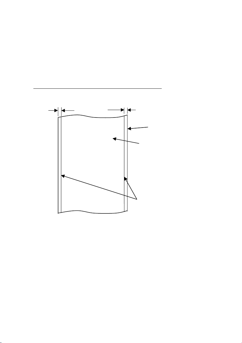
3-4-1. Requirements for full-sheet label paper
To prevent adhesive matter from sticking to the print head or paper guide,
use label paper that has undergone margin removal as shown below.
(Margin removal means cutting the margins at the time of
manufacturing.)
Slits on both sides on the printable side of paper
2 mm or less
2 mm or less
Base paper
Label
Slits
(for margin removal)
18
Page 21
A
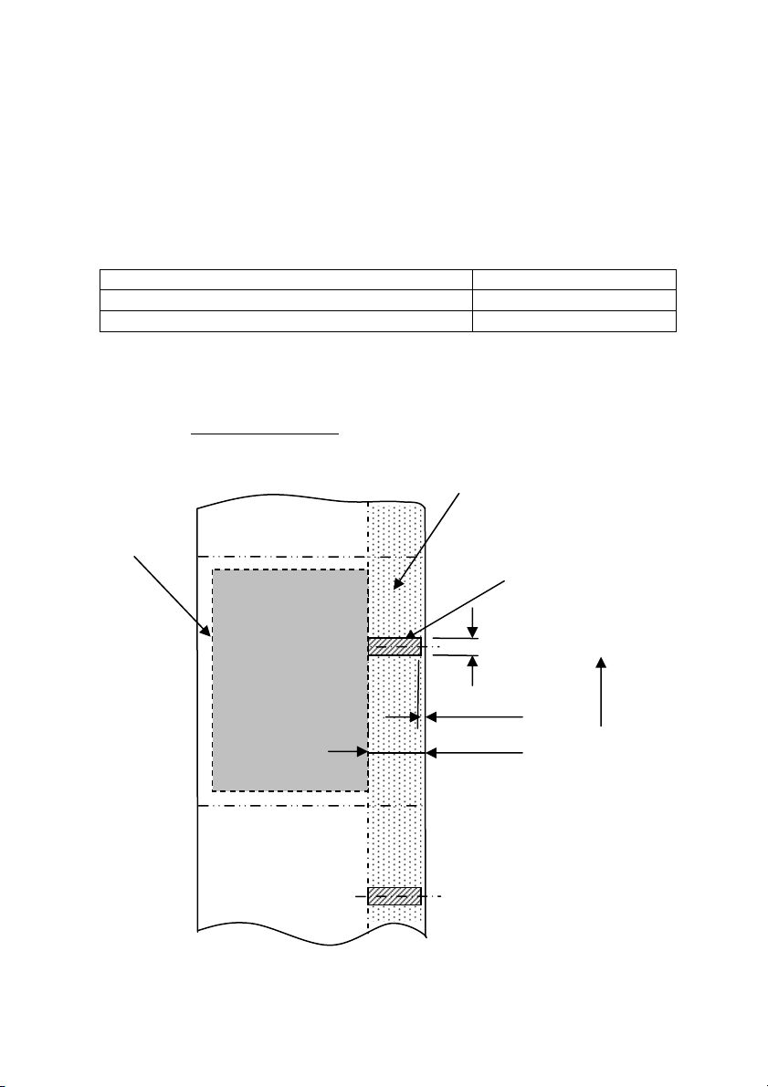
3-4-2. Conditions for using black mark paper
When using receipt paper or full-sheet label paper with black marks,
confirm that the following conditions are satisfied. The reflection factors at
locations A and B on the paper must be the combination of values specified
in the table below.
Reflection factor
A: Black mark area 8%
B: Margins above or below black marks 75%
Note: The reflectivity values were measured using a Macbeth PCM II
density meter (Filter C).
Print area
(seen from the
back side of
paper)
Back side of paper
(back of the coloring side of paper)
B
5.0 to 5.5 mm
0 to 1 mm
10 to 12 mm
Paper feed
direction
19
Page 22
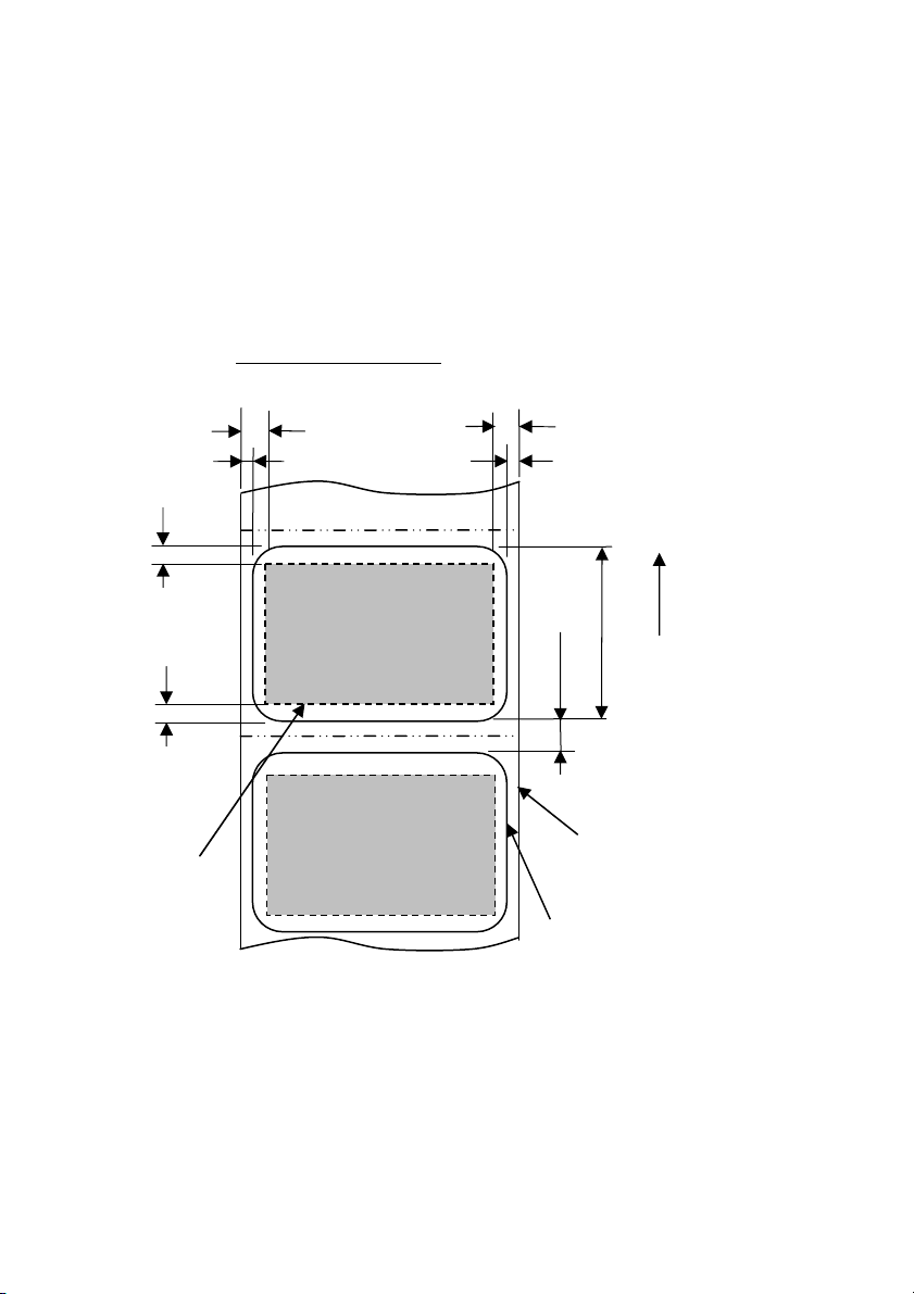
3-4-3. Conditions for using die-cut label paper
When using die-cut label paper, confirm that the following conditions are
satisfied. When using die-cut label paper with black marks, confirm that
the conditions stated in Section 3-4-2, "Conditions for using black mark
paper," are also satisfied.
Printable side of paper
4.5 mm or more
2 0.5 mm
4.5 mm or more
0.5 mm
2
1.5 mm or more
Paper feed direction
15 to 101.6 mm
3 to 10 mm
1.5 mm or more
Print area
Base paper
Label
Note: The base paper's opacity (ISO) must be equal to or less than 70%.
20
Page 23
3-5. Recommended Thermal Paper
Manufacturer Product
Ltd.
Nippon Paper
Industries Co.,
Ltd.
Mitsubishi
Paper Mills
Limited
Ricoh Co.,
Ltd.
name
PD160R Monochrome receipt paper
PD190R Monochrome receipt paper
TF60KS-EX Monochrome receipt paper
TP60KS-FN Monochrome receipt paper
HD75 Monochrome label paper
P220AE-1 Monochrome thick paper
PB670 Two-color thermal paper
PB770 Two-color thermal paper
150LHB Monochrome label paper
Note : A recommended type of paper must be used. If a type of paper other than
a recommended one is used, head damage, printing irregularities, or
similar problems may occur.
Note : To use two-color thermal paper, set the print color to two colors from the
printer setup menu or using the setup tool contained on the CD-ROM
provided with the printer.
(See Example (3) in Section 10-2, "Setting Up the Printer.")
* By setting the appropriate property (use Color on the Graphics tab) for
printing with this printer driver, you can easily print in two-color mode
without having to change the printer setup.
Note : Ruled lines or characters containing fine lines (e.g. a serif typeface) tend to
have dull colors when they are printed on two-color thermal paper. For
printing on two-color thermal paper, a thick font (e.g., a sans serif font) is
recommended.
Quality characteristics Paper
(high-grade preservation type)
(mid-grade preservation type)
(normal type)
(mid-grade preservation type)
(normal type)
(normal type)
(red/black: normal type)
(blue/black: normal type)
(high-grade preservation type)
thickness
75m
75m
75m
75m
150m
150m
75m
75m
150m
specification
Density
100% Oji Paper Co.,
100%
100%
100%
130%
100%
105%
100%
130%
21
Page 24

Note : Red or blue printing on two-color thermal paper has an inferior preservation
characteristic that is equivalent to that of normal thermal paper.
Note : Printouts on label paper or thick paper may contain blurs or voids,
depending on the humidity and other environmental conditions.
Adjust the print speed and print density as appropriate for the type of paper
used.
(See Examples (1) and (2) in Section 10-2, "Setting Up the Printer.")
In particular, note that the paper transport accuracy may be negatively
affected by printing a barcode in the top margin at the beginning of paper
transport or in the Lower margin at the end of paper transport.
Note : The outside core diameter is assumed to be 32 mm.
If roll paper with an outside core diameter of other than 32 mm is used,
the paper-near-end detection accuracy deteriorates.
Note : If roll paper with an outside core diameter of less than 32 mm is used, a
transport error may occur when the cutter cuts the paper in full cutting
mode and reaches the core.
22
Page 25

4. Preparations
No printer cable is provided with the product. Obtain a printer cable suitable for
the product interface. If you have any questions, consult your dealer. Before
connecting or disconnecting cables, make sure of the following:
1) The power to the printer and all other devices connected to the printer
is turned off.
2) The AC adapter power cable has been unplugged from the outlet.
4-1. Connecting Interface Cable
Open the connector cover at the rear of the printer by pulling it up, and connect
the interface cable to its rear connector socket. Close the cover after connecting
the cable.
Note: If cables are arranged so that they extend from the rear or from the rear on
the right side, remove the inserts in the connector cover or the cover with
nippers or a similar tool. Unless the inserts are removed in this case, the
cables may be damaged and cause a failure.
23
Page 26
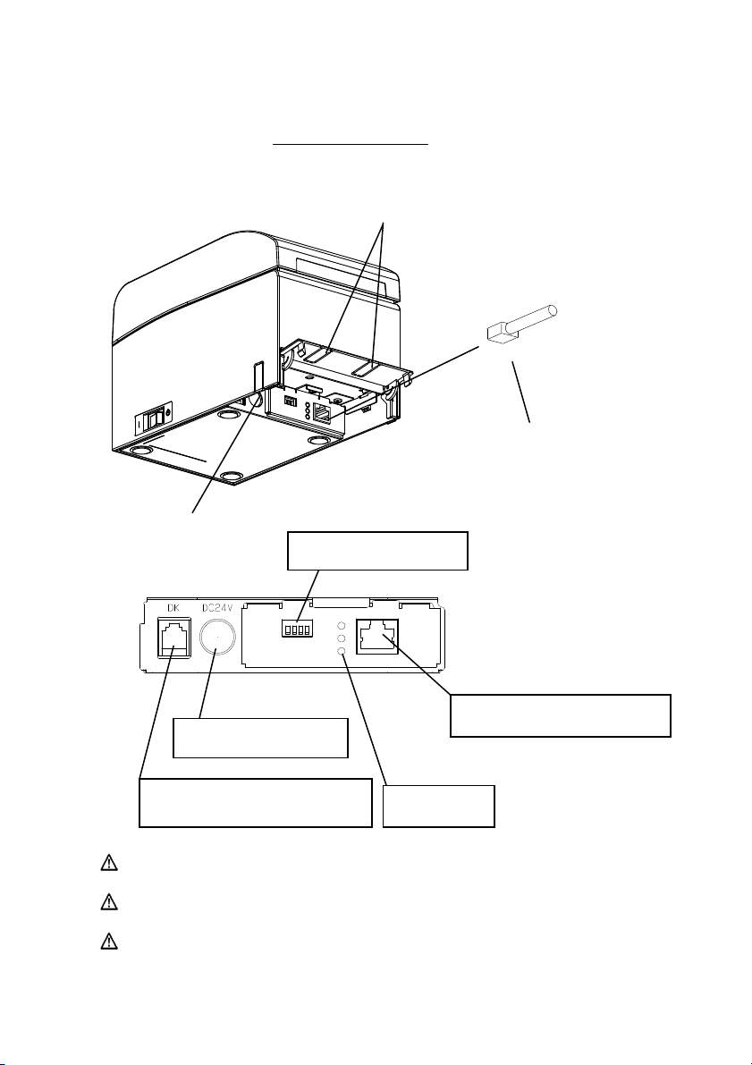
LAN interface model
Connector Cover
Insert
LAN interface cable
Insert
DIP switches
Power connector
LAN interface connector
Drawer kick connector
LEDs
Caution: Do not touch the DIP switches during normal use. This may
Caution: If the device is installed vertically, the LAN cable may not usable
Caution: The LAN interface cable must use the shield type.
change the network settings, disabling normal printing.
due to its shape. Please check before installing.
24
Page 27
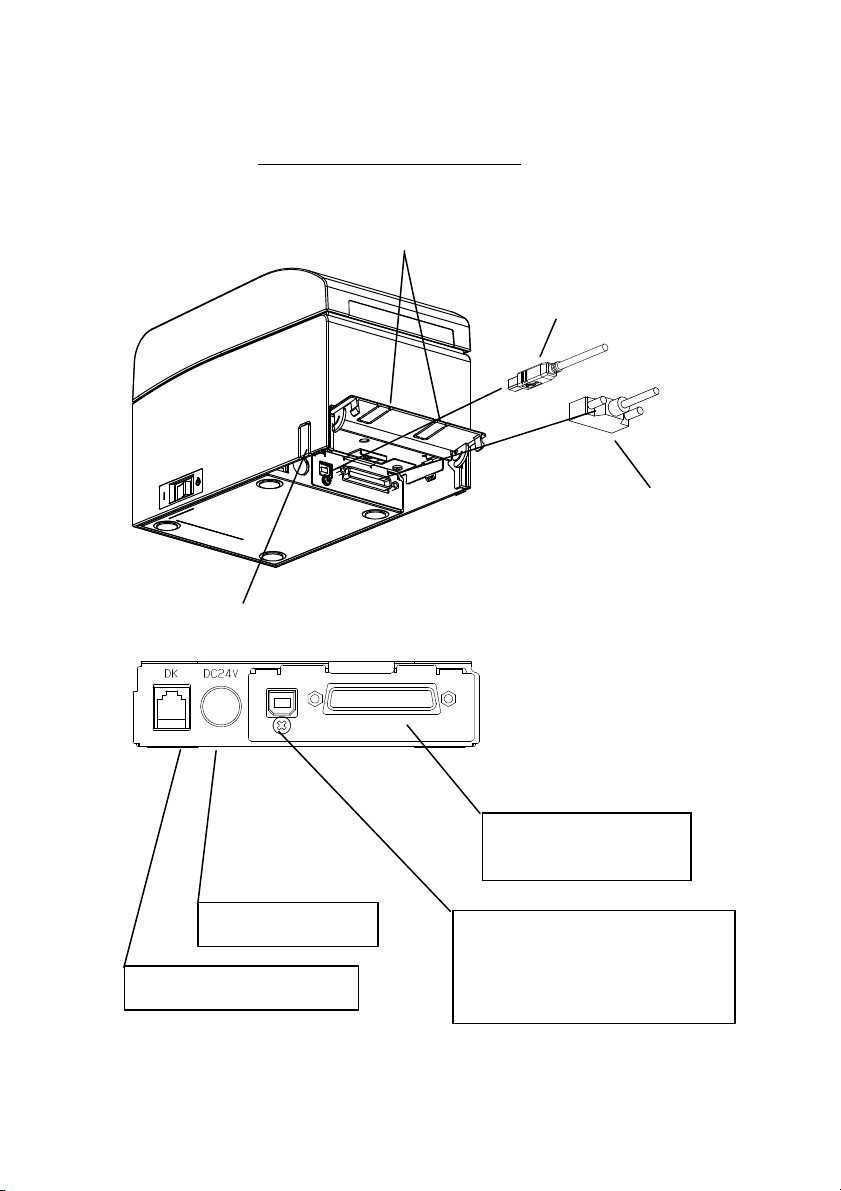
For a unit with Dual interface
Connector cover
Insert
USB Interface Cable
Type-B
* Connect the printer to a PC
through this connector.
Insert
Serial interface cable
* Secure the connector with
screws after making the
connection.
Interface connector
(Serial interface)
Power connector
Drawer kick connector
25
Interface Connector
(USB Interface Type-B)
* Connect the printer to a PC
through this connector.
Page 28
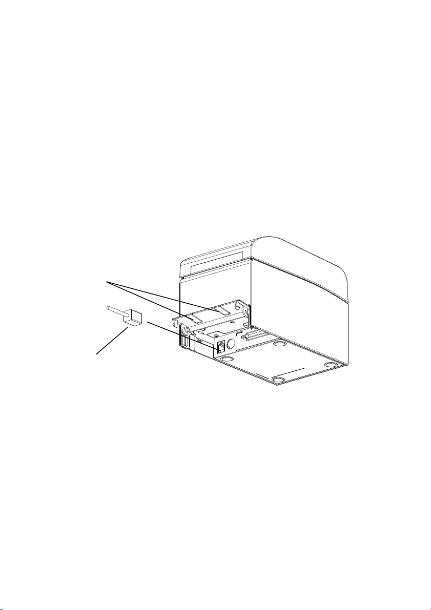
4-2. Connecting the drawer kick cable
Open the connector cover at the rear of the printer by pulling it up, and connect
the drawer kick cable to its rear connector socket. Close the cover after
connecting the cable.
Note : If the cable is arranged so that it extends from the rear, remove the inserts
in the connector cover with nippers or a similar tool. Unless the inserts are
removed in this case, the cable may be damaged and cause a failure.
Note : The drawer kick cable must not be used for a purpose other than for control
of the drawer.
Connector cover
Insert
Drawer kick cable
26
Page 29
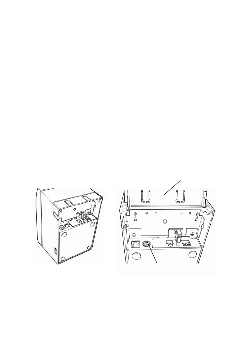
4-3. Connecting the AC Adapter
(1) Connect the AC adapter to the AC adapter power cable.
Note: To connect or disconnect the AC adapter, turn off the power switches of the
printer and all the devices to be connected to the printer. Then, unplug the
plug of the AC adapter power cable from the electrical outlet.
Note: Use only the specified AC adapter and specified AC adapter power cable.
(2) Open the connector cover at the rear of the printer by pulling it up, and
connect the AC adapter cable to the power socket.
Close the cover after connecting the cable.
Note: To connect the AC adaptor, place the printer on its side to make the
connection operation easier to perform.
Note: Remove notch of connector cover with Nipper, to maintain the space for the
cable of AC adapter.
Otherwise, the cable may be damaged and it way cause a failure.
Connector cover
Printer placed on its side
Power connector
27
Page 30
Note: To prevent the adaptor from slipping out, the connector section is
designed to be tight to fit. When inserting, (1) pinch the base of the cable,
(2) while sliding the outer section of the connector upwards, (3) and
insert the connector until it locks in place with a “click” sound.
Base of the cable
Outer section of
the connector
1
2
3
(3) Connect the plug of the power cable to electrical outlet.
(4) Plug the other end of the power cord into the power outlet.
28
Page 31

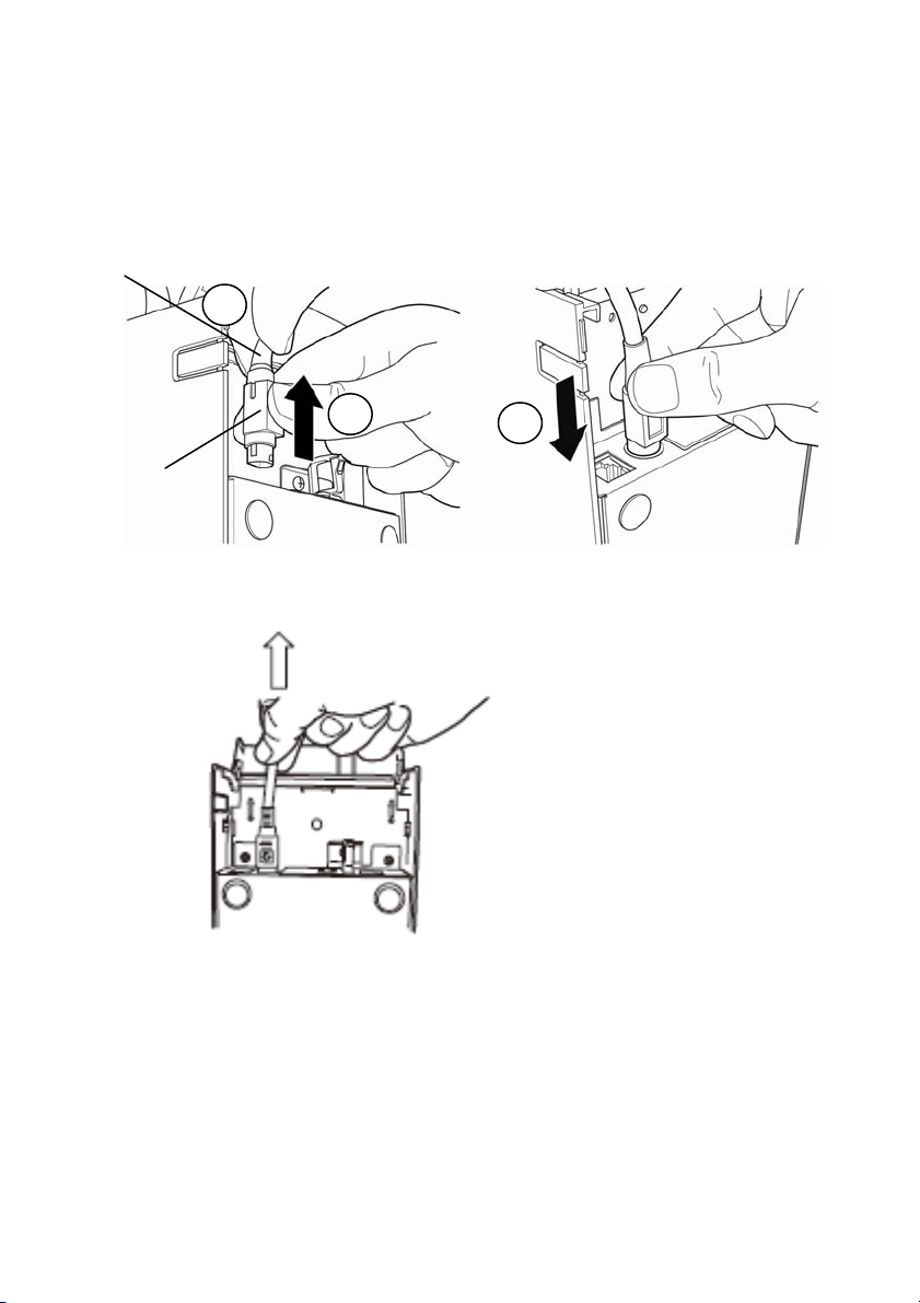
4-4. Disconnecting the AC Adapter
To unplug the AC adapter cable, grasp the connector as shown in the
picture below and pull it out. The lock mechanism of the connector will
then disengage, and the cable can be unplugged easily. Conversely,
forcibly pulling on the cable itself may damage the connector.
Note: Before disconnecting the AC adapter, switch off the printer and all devices
connected to the printer, and also disconnect the power cable of the AC
adapter from the outlet.
29
Page 32

4-5. Turning on the Power
After the AC adapter is connected, turn on the power switch at the side of the
printer. The POWER lamp on the control panel lights.
Control panel
Power switch
30
Page 33

5. Inserting Paper for Printing
5-1. Opening the Top Cover
(1) Grasp the top cover, pull up the cover release lever, and open
the top cover.
Top part of the top cover
Bottom part of the cover
release lever
(2) When manipulating the top cover, note that the cover seems to lock in
position before it is open completely. Make sure that the cover is really
open completely as shown in the picture below.
Note: If the top cover is not open completely during maintenance, it may close
inadvertently.
31
Page 34

5-2. Setting the Paper Width
Separator A is set to the position for a paper width of 70 mm at the time of
shipment from the factory.
- By adjusting the position of separator A, you can use paper with a width
within a range of 70 to 25.4 mm. (See "Section 5-2-1. Attaching separator A.")
- To use paper with a width of 80 mm, remove separator A.
(See "Section 5-2-2. Removing separators A and B.")
- To use paper with a width of 83 mm, remove separators A and B.
(See "Section 5-2-2. Removing separators A and B.")
Note : When replacing the separator, set a paper width appropriate to the
print area, referring to "Special Modes."
(See Examples (7) in Section 10-2, "Setting Up the Printer.")
Note : If the printer is using narrow paper (e.g., width of 70 mm), do not replace
the paper with wide paper (e.g., width of 80 mm). In printing with
narrow paper, part of the thermal head (the part where there is no
paper) comes in direct contact with the platen roller. The resulting wear
may lead to a deterioration in print quality. Similarly, if the paper width
is changed such that the cutter blade cuts at a location that has no paper,
the resulting wear on the blade may lead to improper cuts.
Note : Do not touch the thermal head except during cleaning. Doing so may
result in damage from static electricity.
Thermal head
32
Page 35

5-2-1. Mounting separator A
Holding separator A at locations a (lever) and b, slide the lever to the desired
position. Then, set the separator in place. Use the scale as necessary.
Note: Separator A must be set in place with an allowance of about 0.5 mm for
the maximum paper width.
Location b
Location a (lever)
1
Scale
2
Separator A
33
Page 36

5-2-2. Removing separators A and B
(1) Removing separator A
While holding part b on separator A with part a (lever) pushed in the
arrow-indicated direction, lift it to disengage the lock, and then remove the
rear bearing section.
Location b
Location a (lever)
Separator A
Lock
Rear bearing section
Separator A
34
Page 37

(2) Removing separator B
Holding separator B at location a, lift the s
Then, remove the separator at the rear bearing section.
eparator to disengage the lock.
Rear bearing section
Lock
Location a
Separator B
Separator B
35
Page 38

5-2-3. Attaching separators A and B
(1) Attaching separator A
Attach separator A from the rear bearing section.
Rear hook for the axis
Aligned horizontally
Note : Push the separator down until it engages with an audible click, and confirm
that the top of the separator is aligned horizontally.
36
Page 39

(2) Attaching separator B
Attach separator B from the rear bearing section.
Rear hook for the axis
Aligned horizontally
Note : Push the separator down until it engages with an audible click, and confirm
that the top of the separator is aligned horizontally.
37
Page 40

5-3. Loading Paper
5-3-1. Loading roll paper
(1) When using a new paper roll, remove the glued portion of the paper as
well as the part to which adhesive tape is affixed.
Note : Since the glued portion of the paper should not be printed on, remove about
one turn (about 40 cm) of the roll paper from the beginning so that none of
the remaining paper has glue on it.
Any adhesive or other matter remaining from the glue may adhere to the
thermal head and cause a problem, such as voids on printouts. Therefore,
do not forget to remove the glued portion of the paper.
(2) From the front of the printer, pull out the end of the paper as shown below.
Front cover of the printer.
Note: Pull the end of roll paper until it comes out from the front of the cover.
38
Page 41

Note : Before loading a new roll, make sure that an old core does not remain in
the roll holder. Leaving an old core will cause a paper-near-end error
condition.
Paper not protruding
from the front cover
e : The roll paper mus
Not
shown in the figure below may cause a paper jam, uneven printing, or other
printing problem.
t have no deformities. Using roll paper such as that
Roll paper inserted
upside down
Note : If the loaded roll paper is loose (slack) as shown below, take up the slack
before printing on the paper. Printing on roll paper that is loose may cause
a paper jam, uneven printing, or other printing problem, which will prevent
the printer from detecting paper near end conditions.
39
Page 42

5-3-2. Loading fanfold paper
(1) Load the fanfold paper with its thermo sensitive side facing up.
(2) Open the top cover, and then pass the fanfold paper through the paper
feed section at the rear of the printer.
Paper feed section
Load the paper with its
thermo sensitive side
facing up.
Note: Pull the end of fanfold paper until it comes out from the front of the cover.
40
Page 43

Figure 1
Max 180mm
20 mm or more
Figure 2
Max 80mm
Note: Fanfold paper must be placed at least 20 mm from the rear of the
printer. When this requirement is satisfied, paper can be stacked up to
180 mm (see Figure 1).
When fanfold paper is placed in contact with the rear of the printer,
paper can only be stacked up to 80 mm (see Figure 2).
Note: Also, the paper location must be confined to an area between the left
and right edges of the printer.
41
Page 44

Note: When using perforated paper, make sure that the printer does not
cut the paper at perforations or in an area that is 0 to 15 mm in
front of perforations (as viewed from the paper feed direction).
Otherwise, incorrect cutting may result. (See Figure 3.)
Note: When using perforated paper, be sure to prevent paper from being
caught, paper jams, paper from being cut during transport, and
other such problems. These problems may shorten the life of the
thermal head.
Area that is 0 to 15 mm in front of perforations
(cutting prohibited in this area)
Paper feed direction
Fold at perforations
Figure 3
Note: Should you find that the blinking ERROR lamp annoys you, perform
printer setup to change PNE DETECT to DISABLE.
(See Example (6) in Section 10-2, "Setting Up the Printer.")
42
Page 45

5-4. Setting the Paper Guide
When the print length per print session is longer than 50 mm, use the printer
with the paper guide open. When it is equal to or less than 50 mm, use the
printer with the paper guide closed.
Paper guide
For print length equal to or less than 50 mm:
Use the printer with the paper guide closed.
Paper guide
For print length longer than 50 mm:
Use the printer with the paper guide open.
43
Page 46

5-5. Closing the Top Cover
Place the paper in the correct orientation, and carefully close the top cover.
Release lever
Note : Place the paper in t
the paper is not correctly in place, a paper jam or misaligned printing
might occur.
Note : To close the top cover, press it down near its center (the location pointed
at in the figure below) until you hear the lock engage. If the cover is not
completely locked, printing might be impossible
Press
here
Top cover
he correct orientation. If the top cover is closed while
44
Page 47

6. Setting Up the Printer
Introduction to printer setup procedures
You can set the following items for this printer:
(1) Paper type and paper layout
- Die-cut label paper, black mark paper, or plain paper
- Paper width and other paper layout information
(2) Custom paper creation
(3) Sensor adjustment
(4) Print speed
(5) Print density
(6) Printer operation
Item (1), (2) is a required setting.
Items (3) to (6) are optional settings.
<Reference documents>
The CD-ROM that comes with the printer contains some PDF-formatted
online manuals.
For details on how to install and use each of the software programs
that come with the printer, see the following documents:
Document title Folder File name
Installation Guide \Manuals LD670_InstallGuide1_en.pdf
Windows Driver User’s Guide \Manuals LD670_WindowsDriverGuide_en.pdf
Utility User’s Guide \Manuals LD670_UtilityGuide_en.pdf
Status Monitor User’s Guide \Manuals LD670_StatusMonitorGuide_en.pdf
45
Page 48

Detection of paper layout information
The printer supports the following paper types:
a. Plain paper (including full-sheet label paper)
b. Black mark paper
c. Die-cut label paper (including die-cut label paper with black
marks)
When using black mark or die-cut paper, the printer can move the paper to the
start position, cutting position, peeling-off position, or tear-off position
according to the paper layout settings.
To use this function, provide the printer with paper layout information,
including the paper type and size, before printing. Use of the printer without
these settings may result in a paper layout error or unexpected printouts.
Therefore, set the paper layout when you:
(1) use label paper for the first time,
(2) change the paper type (plain paper, black mark paper, or die-cut label
paper),
(3) change the paper size, or
(4) switch to die-cut label paper of the same size as the current paper but
with a different base color or other specification.
You can set the paper layout automatically or manually. The next and
subsequent pages provide detailed information.
Note: The paper layout must be set under the same temperature
conditions as in the actual operating environment of the printer.
Otherwise, the cutting position may be outside the base area for
labels because of a temperature difference.
Note: - The printer provides a function that automatically detects the paper
layout. This automatic layout detection function obtains fixed
information on width settings. Therefore, OKI recommends that you
manually specify these settings.
Note: - There are two ways to manually set up the printer:
(1) Paper information setting using the driver
(2) Paper information setting using the utility
46
Page 49

6-1. Paper Information Setting Using the Driver
Printer setup flow
I. Installing the driver
↓ See "Chapter 3 Installation" in the
II. Paper layout detection
↓ Provide the printer with the paper layout information described in the
Manual Section 6-1-1, "Paper layout."
III. Custom paper creation
↓ Create your custom paper as described in the Manual Section 6-1-2,
"Custom paper."
IV. Printing from an application
Perform printing as described in the Manual Section 6-1-3,
"Printing from an application." (The use of WordPad is assumed for
the procedure described in Section 6-1-3.)
Installation Guide
.
47
Page 50

6-1-1. Paper layout
The printer shipped from the factory is configured to enable automatic
paper detection. Follow the procedure below to have the printer
automatically detect the paper layout information.
<<Procedure>>
(1) Turn on the printer power.
(2) Open the top cover.
(3) Load the paper that you want to use into the printer.
Leave the top cover open.
(4) Press and hold down the FEED switch. The POWER and ERROR lamps
blink alternately. Continue to hold down the FEED switch until the
POWER and ERROR lamps blink at the same time. At this time, release
the FEED switch.
(For details on how to initialize the paper layout, see "How to initialize
the paper layout" in Section 7-1, "Control Panel.")
(5) Close the top cover.
(6) The printer feeds the paper, automatically obtains paper layout
information, and saves the information.
Note: Automatic layout detection involves a paper feed of several tens of
centimeters. This is normal operation.
48
Page 51

6-1-2. Custom paper
The printer driver provides a function that allows you to set printer layout
information when creating a custom type of paper.
The layout information can be updated even with the printer in
paper-layout-error status.
Note: When changing the paper type to plain paper from another type, you
must initialize the layout information by following the procedure
described in "How to initialize the paper layout" in 7-1 Section,
"Control Panel."
Follow the procedure below to register layout information with the printer.
This procedure indicates how to create a custom paper type and send the
resulting information to the printer. The use of Windows XP Professional is
assumed for the screen shots used in the procedure.
1. Click [Start] and then [Printers and Faxes].
* The method of opening the printer folder varies depending on the
Windows version.
For details on how to open the printer folder, see "Section 3.1.1 How to
Display the Printer Properties" in the
2. Right-click [LD670 Raster], and then select [Properties].
3. Click the [Custom Paper] tab.
Windows Driver User's Guide
.
49
Page 52

(1) Creating a new custom paper type
<<Procedure>>
(1) Check the [Create a New Paper] check box and enter the paper name.
(2) Select [Paper Type] and enter the appropriate paper information ([S1] to
[S5]). Do not change [S5] (cut position) with its default value.
(3) Enter the left, right, top and bottom margins.
(4) Click the [Save] button.
This registers your custom paper settings in the printer driver as paper
size information.
(5) Click the [Transfer to Printer] button.
The selected paper layout information is sent to the printer and becomes
effective.
(6) Go to step 4.
50
Page 53

(2) Using an existing type of paper
<<Procedure>>
(1) Select the desired paper that has already been created.
(2) Click the [Transfer to Printer] button.
The selected paper layout information is sent to the printer and becomes
effective.
(3) Go to step 4.
51
Page 54

4 When a confirmation message appears, respond as instructed and then click
the [OK] button.
* You may encounter a paper layout error when attempting to replace paper
in one of the following patterns:
- Change from die-cut label paper to plain paper
- Change from black mark paper to plain paper
- Change from die-cut label paper to black mark paper
- Change to paper having a different paper layout
* If the error remains even after setting is completed, re-verify that the paper
loaded on the printer matches the custom paper setting.
* The [Transfer to Printer] button works even when the new paper is not
loaded. Before actually printing data, however, be sure to replace the
paper.
* If the newly set type of paper is not plain paper, the printer feeds paper up
to the top-of-form position.
5 In the LD670 Raster Properties window, click the [OK] button.
52
Page 55

6-1-3. Printing from an application
You can print a document from an application using paper information
registered in the printer driver.
The procedure below explains how to print a document to the LD670 printer
using WordPad as an example.
1. From the WordPad [File] menu, select [Page Setup].
2. The Page Setup window appears. Click the [Print Setup] button.
3. In the [Printer Name] field, specify [LD670 Raster] as the target
printer.
4. Click the [Properties] button to configure printing preferences for the printer
driver.
* The button used to open the printing preferences window varies from one
application to another. For example, the [Options] button is used for this
purpose in Excel.
* Some applications (including Word) also assume use of the Print window
for setting printing preferences, instead of providing a separate Page
Setup window.
For details on the Print window, see the description in step 10 later.
5. The LD670 Raster Properties (printing preferences) window appears. Specify
desired printing preferences, and then click the [OK] button.
6. Click the [OK] button in the Page Setup window to close the window.
7. In Page Setup window, specify the paper size, orientation and margins, and
then click the [OK] button.
8. Edit a document in the WordPad edit window.
9. Select [Print] from the [File] menu.
10. The [Print] window appears.
Click the [Advanced] button to specify printing preferences for the printer
driver.
11. Specify [Page Range] and [Copies] when necessary, and then click the [Print]
button.
12. Print data is sent to the printer and printing starts.
53
Page 56

6-2. Paper information setting using the utility
6-2-1. Paper layout
The printer shipped from the factory is configured to enable automatic
paper detection. Follow the procedure below to have the printer
automatically detect the paper layout information.
<<Procedure>>
(1) Turn on the printer power.
(2) Open the top cover.
(3) Load the paper that you want to use into the printer.
Leave the top cover open.
(4) Press and hold down the FEED switch. The POWER and ERROR lamps
blink alternately. Continue to hold down the FEED switch until the
POWER and ERROR lamps blink at the same time. At this time, release
the FEED switch.
(For details on how to initialize the paper layout, see "How to initialize
the paper layout" in Section 7-1, "Control Panel.")
(5) Close the top cover.
(6) The printer feeds the paper, automatically obtains paper layout
information, and saves the information.
Note: Automatic layout detection involves a paper feed of several tens of
centimeters. This is normal operation.
54
Page 57

6-2-2. Setting detailed paper layout information
The printer utility provides a function that allows you to set printer layout
information.
The layout information can be updated even with the printer in
paper-layout-error status.
Follow the procedure below to register layout information with the printer.
This procedure explains how to send layout information to the printer.
The use of Windows XP Professional is assumed for the screen shots.
1. Click [Start], [All Programs], [Okidata], and [LD670 Utility] in this order.
* The method of running the printer utility varies depending on the Windows
version. See "Section 3.1 Starting LBL32" in the
2. Select [LD670 Raster] and then click [OK].
3. Click the [Paper Layout] tab.
Utility User's Guide
.
55
Page 58

<<Procedure>>
(1) Uncheck the [Automatically set the paper layout] check box.
(2) Select [Paper Type] and enter the appropriate paper information ([S1]
to [S5]). Do not change [S5] (cut position) with its default value.
(3) Enter the left, right, top and bottom margins as required.
(4) Click the [Set Layout] button.
The paper layout information you entered in this window is sent to
the printer and becomes effective.
56
Page 59

4 When a confirmation message appears, respond as instructed and then click
the [OK] button.
5 A message appears, prompting you to replace the paper with paper targeted
by the layout setting. Replace the paper and click the [OK] button.
* If the error remains even after setting is completed, re-verify that the
paper loaded on the printer matches the paper setting.
* If the newly set type of paper is not plain paper, the printer feeds paper up
to the top-of-form position.
57
Page 60

6-3. Setting Paper Information Using the Printer
6-3-1. Automatic layout detection
The printer shipped from the factory is configured to enable automatic
paper detection. Follow the procedure below to have the printer
automatically detect the paper layout information.
<<Procedure>>
(1) Turn off the printer power.
(2) Open the top cover.
(3) Turn on the printer power.
(4) Load the paper that you want to use into the printer.
Leave the top cover open.
(5) Press and hold down the FEED switch. The POWER and ERROR
lamps blink alternately. Continue to hold down the FEED switch
until the POWER and ERROR lamps blink at the same time. At
this time, release the FEED switch.
(For details on how to initialize the paper layout, see "How to
initialize the paper layout" in Section 7-1, "Control Panel.")
(6) Close the top cover.
(7) The printer feeds the paper, automatically obtains paper layout
information, and saves the information.
Note: Automatic layout detection involves a paper feed of several tens of
centimeters. This is normal operation.
Note: The printer’s automatic layout detection function cannot obtain the
paper width setting as part of paper information. For details on how to
set the paper width, see Example 7) in Section 10-2, "Setting Up the
Printer."
Note: If you need to specify information other than the paper width, follow
the procedure described in Section 6-1, "Paper Information Setting
Using the Driver," or 6-2, "Paper Information Setting Using the
Utility."
58
Page 61

6-3-2. Setting the Paper Width
The printer utility provides a function that allows you to set a paper width on
the printer.
The paper width can be set even with the printer in paper-layout-error status.
Follow the procedure below to set a paper width on the printer.
This procedure explains how to send your paper width setting to the printer.
The use of Windows XP Professional is assumed for the screen shots.
1. Click [Start], [All Programs], [Okidata], and [LD670 Utility] in this order.
* The method of opening the printer folder varies depending on the
Windows version.
For details on how to open the printer folder, see "Section 3.1, Starting
LBL32" in the
2. Select [LD670 Raster] and then click [OK].
3. Click the [Paper Layout] tab.
Utility User's Guide
.
59
Page 62

<<Procedure>>
(1) Enter the paper width.
(2) Click the [Layout Auto Set] button.
4 When a confirmation message appears, respond as instructed and then
click the [OK] button.
5 A message appears, prompting you to replace the paper with paper
targeted by the layout setting. Replace the paper and click the [OK]
button.
Note: Automatic paper size setting involves a paper feed of several tens of
centimeters for layout detection. This is normal operation.
60
Page 63

6-3-3. Automatic layout detection
The automatic layout settings are configured as follows:
Black mark paper
L1: Length from the vertical reference position to the next reference
Position : Automatically detected
L2: Length of the detection area for the vertical reference position
: 5.0mm to 5.5mm
L3: Length from the vertical reference position to the start position
: 1.5mm
L4: Length from the vertical reference position to the cutting position
L5: Print area length : (L1 - 1.5 x 2) mm
L6: Length from the left edge of the paper to the left end of the print area
: 11.0 mm (for a paper width of 83 mm)
: 4.0 mm (for a paper width of 80 mm)
: 3.0 mm (for other paper widths)
L7: Print area width : 80.0 mm (for a paper width of 83 mm)
(Paper width - L6 x 2) mm (for other paper widths)
Note: L1 to L7 above are values detected by the printer sensor.
These values do not match the S1 to S5, L, R, T, and B parameter
values specified by the driver or utility.
Note: If the paper length (L1) of the loaded roll paper differs by 10% or
more from the initially set paper length (L1) or that set upon
automatic recognition, an error occurs because the type of loaded
roll paper is considered illegal.
L4
L3
L6
Print Area
L5
L7
: 0.0mm
Paper feed direction
L2
L1
Base Position
61
Page 64

Die-cut label paper
L1: Length from the vertical reference position to the next reference position
: Automatically detected
L2: Length of the detection area for the vertical reference position
: Automatically detected
L3: Length from the vertical reference position to the start position
: (L2/2 + 1.5) mm
L4: Length from the vertical reference position to the cutting position
: 0.0 mm
L5: Print area length : (L1 - L3 x 2) mm
L6: Length from the left edge of the paper to the left end of the print area
: 5.0 mm
L7: Print area width : (Paper width setting - L6 x 2) mm
Note: L1 to L7 above are values detected by the printer sensor.
These values do not match the S1 to S5, L, R, T, and B parameter
values specified by the driver or utility.
Note: If the paper length (L1) of the loaded roll paper differs by 10% or
more from the initially set paper length (L1) or that set upon
automatic recognition, an error occurs because the type of loaded
roll paper is considered illegal.
Paper feed direction
L5
L4
L3
L7
Print Area
L2
Base Position
L1
L6
62
Page 65

Plain paper (including full-sheet label paper)
L1: Length from the vertical reference position to the next reference position
: Not determined
L2: Length of the detection area for the vertical reference position
: Not determined
L3: Length from the vertical reference position to the start position
: Not determined
L4: Length from the vertical reference position to the cutting position
: Not determined
L5: Print area length : Not determined
L6: Length from the left edge of the paper to the left end of the print area
: 1.0 mm (for a paper width of 83 mm)
: 4.0 mm (for a paper width of 80 mm)
: 3.0 mm (for other paper widths)
L7: Print area width
: 80.0 mm (for a paper width of 83 mm)
(Paper width - L6 x 2) mm (for other paper widths)
Note: L1 to L7 above are values detected by the printer sensor.
These values do not match the S1 to S5, L, R, T, and B parameter
values specified by the driver or utility.
Paper feed direction
L7
Print Area
L6
63
Page 66

6-4. Replacing paper
The paper replacement procedure is as follows.
Automatic layout detection
<<Procedure>>
(1) Turn off the printer power, and open the top cover.
(2) Turn on the printer power.
(3) Load the paper that you want to use into the printer.
Leave the top cover open.
(4) Press and hold down the FEED switch. The POWER and ERROR
lamps blink alternately. Continue to hold down the FEED switch
until the POWER and ERROR lamps blink at the same time. At
this time, release the FEED switch.
(5) Close the top cover.
(6) The printer feeds the paper, automatically obtains paper
information, and saves the information.
Note: Automatic layout detection involves a paper feed of several
tens of centimeters. This is normal operation.
Updating the layout information
Re-specify paper information by following the procedure described in
Section 6-1-2, "Custom paper," or 6-2-2, "Setting detailed paper layout
information."
64
Page 67

6-5. Paper Layout Errors
When using black mark or die-cut label paper, the printer monitors the
paper length (L1) based on the set paper layout. If the detected paper
length does not match the set paper length, a paper layout error occurs.
(1) Error when paper is being loaded
Confirm that the paper being loaded is the same as the paper specified
in the paper layout information for the printer. If not, replace the paper
with paper that matches the paper layout information.
(2) Error during printing
If a paper layout error occurs during printing, open the top cover, check
whether label peeling, a paper jam or other problem has occurred,
reposition the paper, and then close the top cover.
(3) Error when paper is being replaced
Follow the procedure in "Section 6-4. Replacing paper."
Note: If the paper length (L1) of the loaded paper is 10% different from
your specified paper length or that set through automatic detection,
a paper layout error occurs.
65
Page 68

6-6. Adjusting Sensors
1) There are two ways to adjust sensors:
a. Automatic sensor adjustment (This mode is set at the time of shipment
from the factory.)
b. Manual sensor adjustment
■ Automatic sensor adjustment
1) With this mode enabled, the sensor is automatically adjusted in
parallel with automatic layout detection. This adjustment sets
optimal values based on the measured sensor input level.
Sensor adjustment values are not preset at shipping. However, when
you load paper on the printer and initially power on the printer, the
automatic layout detection function will set the sensor adjustment
values.
■ Manual sensor adjustment
1) You can start manual adjustment of a sensor by selecting the sensor in
sensor adjustment mode, which is a special mode. The printer prints
instructions for operations. Adjust the sensor by following these
instructions.
2) Automatic sensor adjustment is enabled at the time of shipment from
the factory. The printer as shipped need not be manually adjusted
because sensors are automatically adjusted at the same time as
automatic layout detection. Adjust sensors manually only if a paper
layout error frequently occurs.
66
Page 69

6-7. Print Density Setting
The printer can specify a print density for the paper to be used.
The print density is preset to 130% at shipping. You can change this setting to
the value appropriate for the paper to be used as described in Section 3-5,
"Recommended Thermal Paper."
There are three methods of changing the setting:
(1) Using the Windows printer driver
See "Section 4.4 [Graphics] Tab" in the
(2) Using the printer utility
See "Section 3.2.5 Customize Value" in the
(3) Setting up the printer
Change the setting as described in Example (1) in Section 10-2, "Setting Up
the Printer."
* If you have specified a print density using the Windows driver, the print
density specified by the driver will be used for printing. (The print density
specified by the driver takes precedence over print density specified by
the utility.)
Windows Driver User's Guide
Utility User's Guide
.
.
67
Page 70

6-8. Print Speed Setting
There are three methods of changing the setting:
(1) Using the Windows printer driver
See "Section 4.4 [Graphics] Tab" in the
(2) Using the printer utility
See "Section 3.2.5 Customize Value" in the
(3) Setting up the printer
Change the settings as described in Example (2) in Section 10-2, "Setting Up
the Printer."
* If you have specified a print speed using the Windows driver, the print
speed specified by the driver will be used for printing. (The print speed
specified by the driver takes precedence over print speed specified by the
utility.)
Note: The printer restricts the print speed when using paper with a width of
57 mm or less.
Up to 260 mm/s for a paper width within a range of 83 to 58 mm
Up to 180 mm/s for a paper width within a range of 57 to 38 mm
Up to 80 mm/s for a paper width within a range of 37 to 25.4 mm
Windows Driver User's Guide
Utility User's Guide
.
.
68
Page 71

6-9. Cutting Position Correction
This printer allows you to correct (upward or downward) the top-of-form
position, cut position, peeling-off position and tear-off position. Change the
setting as required.
You can use one of the following methods to change this setting.
(1) Using the Windows printer driver
See "Section 4.1 [Custom Paper] Tab" in the
(2) Using the printer utility
See "Section 4.3 Adjusting Cut Position or Tear Off Position" in the
User's Guide
.
Windows Driver User's Guide
.
Utility
69
Page 72

6-10. Other Settings
This printer allows you to specify whether to feed paper up to the top-of-form
position at power-on and whether to cut paper upon the closing of the cover.
There are two methods of changing the setting:
(1) Setting up the printer
Change the setting as described in Example (4) in Section 10-2, "Setting
Up the Printer."
(2) Using the printer utility
See "Section 3.2.4 Memory Switch settings" in the
Utility User's Guide
6-11. Initializing the Printer Setup Information
You can disable the settings you specified on the printer and restore the default
settings preset at shipping.
Initialize the settings as described in Example 5) in Section 10-2, "Setting Up
the Printer."
.
70
Page 73

7-1. Control Panel
7. Control Panel
POWER lamp (●)
Lights when the power switch is
turned on and power is supplied to
the printer.
ERROR lamp (●)
Lights or blinks to indicate errors.
FEED switch
- Plain paper (including full-sheet label
paper)
Pressing this switch once advances the
paper one line. Holding down this switch
adva
nces paper continuously.
- Paper type other than plain paper
(including full-sheet label paper)
Pressing this switch once feeds one
sheet of paper.
71
Page 74

* How to initialize the paper layout
Pressing the FEED switch with the top cover open initializes the paper layout
information. After initialization is completed, load the paper you want to use
and then close the top cover. The printer feeds paper, automatically retrieves
paper information, and retains the paper layout information.
(1) Initialization
- Initialization initializes the paper layout information. You can use
initialization when changing the layout information while using the same
type of paper.
- Procedure: Press and hold down the FEED switch for a while. The POWER
and ERROR lamps will start blinking alternately. At this time, release the
FEED switch.
(2) Full initialization
- Full initialization initializes the paper type setting in addition to paper
layout information. Use it when you change the type of paper.
- Procedure: Press and hold down the FEED switch for a while. The POWER
and ERROR lamps will start blinking alternately. When you continue
holding down the FEED switch, the POWER and ERROR lamps will blink
simultaneously. At this time, release the FEED switch.
72
Page 75

7-2. Error Indications
Recoverable errors
Error condition
No paper
(paper end)
Cover open
Head hot (*1)
LED LAMP
POWER (●)
ERROR (●)
POWER (●)
ERROR (●)
POWER (●)
ERROR (●)
Blinking pattern
Constantly on
Constantly on
Constantly on
Constantly on
Constantly on
Constantly on
*1 Printing is suspended because of a high thermal head temperature.
Error condition
Paper near end
Paper layout
error
LED LAMP
POWER (●)
ERROR (●)
POWER (●)
ERROR (●)
Constantly on
● ●――――● ●――――
Constantly on
●―●―――――●―●―――――
Repeated blinking of the amber lamp four
times in succession
Blinking pattern
73
Page 76

Unrecoverable errors
Error condition LED LAMP Blinking pattern
Internal error
Head not
installed
Low voltage
Over voltage
Cutter
functioning
abnormally
LF motor
functioning
abnormally
POWER (●)
ERROR (●)
POWER (●)
ERROR (●)
POWER (●)
ERROR (●)
POWER (●)
ERROR (●)
POWER (●)
ERROR (●)
POWER (●)
ERROR (●)
――●―●―
●―――――
Repeated pattern in which the green lamp
blinks twice and the amber lamp blinks once
――●―●―●―
●―――――――
Repeated pattern in which the green lamp
blinks three times and the amber lamp blinks
once
――●―●―●―●―
●―――――――――
Repeated pattern in which the green lamp
blinks four times and the amber lamp blinks
once
――●―●―●―●―●―
●―――――――――――
Repeated pattern in which the green lamp
blinks five times and the amber lamp blinks
once
――●―●―●―●―●―●―
●―――――――――――――
Repeated pattern in which the green lamp
blinks six times and the amber lamp blinks
once
――●―●―●―●―●―●―●―
●―――――――――――――――
Repeated pattern in which the green lamp
blinks seven times and the amber lamp
blinks once
74
Page 77

8. Preventing and Clearing Paper Jams
8-1. Preventing Paper Jams
Do not touch the paper while the paper is being ejected or cut.
Holding or pulling the paper by hand during ejection might cause a paper
jam, incorrect cutting, or a feed error.
8-2. Clearing a Paper Jam
If a paper jam occurs, remove the jammed paper as follows:
(1) Turn off the printer power by turning off the power switch.
(2) Press the cover open lever down, and open the top cover.
(3) Pull out the jammed paper slowly toward the top while holding down the
printer, as shown in the picture below.
Note: Do not pull the paper with excessive force.
Note: Do not touch the thermal head. Doing so may result in damage from static
electricity.
75
Page 78

9. Troubleshooting
This chapter describes the appropriate action to be taken in cases where
the printer is not operating correctly or fails to produce clean printouts.
9-1. Power-on Problems and Errors
Symptom Cause Corrective action
Although the power
has been turned on,
the POWER lamp on
the control panel does
not light and the
printer does not start
up.
The ERROR lamp on
the control panel is lit,
and the printer does
not work.
(1) The power cable is
disconnected.
(2) The connector of the
AC adapter is
disconnected.
(1) No paper is inserted.
(2) The top cover is not
closed completely.
(3) The thermal head is at
a high temperature.
9-2. Cutter-related Problems
Symptom Cause Corrective action
Paper cannot be cut. (1) The cutter blade is
The cutter does not
return to the correct
position.
damaged or worn, or it
has been used for too
long.
(2) Paper fragments or
other foreign matter is
stuck around the
cutter blade or paper
chute.
(3) Adhesive matter is
adhering to the cutter
blade because of
printing on label
paper.
Paper fragments or other
foreign matter is stuck
around the cutter blade
or paper chute.
(1) Connect the power cable.
(2) Connect the connector of
the AC adapter.
(1) Insert paper.
(2) Close the top cover
completely.
(3) Wait until the thermal
head temperature
decreases sufficiently.
(1) Turn off the power, and ask
for repairs.
(2) Remove the paper
fragments or foreign
matter.
(3) Clean the cutter blade to
remove the adhesive
matter.
Remove the paper
fragments or foreign
matter.
76
Page 79

(
(
(
9-3. Printing-related Problems
Symptom Causes Corrective action
Printing does not
begin.
The printing is too
dark or blurry.
Printed characters
are thin (faint).
The print density is
uneven.
Vertical marks
appear on the
printout.
(1) The interface cable is
disconnected or broken.
(2) The printer setup is
incorrect.
(1) The print density setting
included in the printer
setup is incorrect.
(2) The thermal head is
damaged.
(1) The print density setting
included in the printer
setup is incorrect.
(2) The thermal head is
damaged.
(1) Paper fragments or
foreign matter is stuck
on the heating elements
of the thermal head.
(2) The printer setup is
incorrect.
(3) Foreign matter is
adhering to the platen
roller.
(4) The thermal head is
damaged.
1) Foreign matter is stuck
or caught on the paper
transport.
2) Foreign matter is
adhering to the thermal
head
3) The thermal head is
damaged.
(1) Connect the interface cable
correctly, or replace it.
(2) Set up the printer correctly.
Example: An incorrect baud
rate is set.
(See "10-2 Setting Up the
Printer.")
(1) Adjust the print density and
print speed settings of the
printer so that they are
appropriate to the paper.
(See "10-2 Setting Up the
Printer.")
(2) Turn off the power, and ask
for repairs.
(1) Adjust the print density and
print speed settings of the
printer so that they are
appropriate to the paper.
(See "10-2 Setting Up the
Printer.")
(2) Turn off the power, and ask
for repairs.
(1) Check and clean the thermal
head.
(2) Adjust the print density and
print speed settings of the
printer so that they are
appropriate to the paper.
Set up the printer correctly.
(See "10-2 Setting Up the
Printer.")
(3) Remove the foreign matter
from the platen roller.
(4) Turn off the power, and ask
for repairs.
(1) Clean the paper transport.
(2) Clean the thermal head.
(3) Turn off the power, and ask
for repairs.
77
Page 80

10. Special Modes
10-1. Test Printing
With paper inserted in the printer, turn off the printer power switch once, and
turn on the switch again while holding down the FEED switch on the control
panel. Then, the data shown below is printed. When "TEST PRINT" is printed,
press and hold down the FEED switch for one second or longer to start test
printing.
After printing a certain amount of data, the printer automatically cuts the
paper and ends the test printing. To terminate test printing in progress, press
the FEED switch. Then, the printer cuts the paper and terminates the test
printing.
Note: You must hold down the FEED switch until the printer starts printing.
Note: If you have passed the item that you want to select, quickly press the
FEED switch repeatedly until you return to the first item.
Test printing
Test Print
End
Sample Print
Data Analysis
Cleaning
Sensor Adjustment
Setup
Test Print
Selecti on Ite m
Special Mode
Usage
Item Selection
Please push the feed switch short.
Item Decision
Please push the feed switch long.
Paper feed direction
78
Page 81

The printer stops after printing the selection items.
- When you press the FEED switch briefly (one second or less), the printer
ends test printing.
- When you press and hold down the FEED switch for one second or longer,
the printer continues test printing to print a list of fonts. To terminate
printing of the font list in progress, press the FEED switch. The printer
cuts the paper and terminates printing of the font list.
Sample test printout
79
Page 82

10-2. Setting Up the Printer
This section explains how to set up the printer without using a PC.
With the printer connected to a Windows PC, you can easily change the settings
by using the utility software contained on the CD-ROM provided with the
printer.
For details on how to install and run the utility, see "Chapter 3 Installation" in
the
Installation Guide
For details on the functions of the utility and how to use it, see the
Guide
.
This section describes the typical setting changes listed below in detail.
Example (1) Changing the print density to a lower value
Example (2) Changing the print speed to a higher value
Example (3) Changing to use two-color thermal paper
Example (4) Changing the top-of-form position at power-on
Example (5) Initializing the printer settings
Example (6) Disabling paper-near-end detection
Example (7) Changing the paper width
Example (8) Switching to batch printing
.
Utility User's
80
Page 83

Example (1): Changing the Print Density
Change from 130% to 100%
The procedure for this setting is as follows.
1. Before starting work for this setting, verify the following conditions of the
printer:
(1) The power is off.
(2) Roll paper is inserted in it.
(3) The cover is closed.
2. Enter special mode.
Turn on the power switch on the right side of the printer while
holding down the FEED switch on the left part of the Top cover.
Note: You must hold down the FEED switch until the printer starts
printing.
Note: If you have passed the item that you want to select, quickly press the
FEED switch repeatedly until you return to the first item.
The printer prints the following when it enters special mode:
Test Print
End
Sample Print
Data Analysis
Cleaning
Sensor Adjustment
Setup
Test Print
Selecti on Ite m
Special Mode
Usage
Item Selection
Please push the feed switch short.
Item Decision
Please push the feed switch long.
Paper feed direction
81
Page 84

3. Enter setup mode from special mode.
Press the FEED sw
itch briefly (one second or less) once to move to
"SETUP".
Setup
↑
Test Print
End
Sample Print
Data Analysis
Cleaning
Sensor Adjustment
Setup
Test Print
Sele ction Ite m
Then, press and hold down the FEED s
accept th
e selection.
witch for one second or longer to
The printer prints the following when it enters setup mode:
Setup
End
Default Set
Setup Print
Setup
Selecti on Ite m
Setup
Paper feed direction
Paper feed direction
82
Page 85

4. In setup mode, select "SETUP"
Press and hold dow
n the FEED switch for one second or longer to accept the
selection.
The printer prints the following when you accept the selection of "SETUP":
Paper Setting
Return to Top Menu
Others
Serial Condition
Customize Value
Memory Switch
Paper Setting
Selecti on Ite m
Setup
Paper feed direction
83
Page 86

p
y
5. Select "CUSTOMIZE VALUE" as your option.
Quickly press the FEED switch twice (up to one second each) to move
to "CUSTOMIZE VALUE".
Customize Value
↑
Memory Switch
↑
Paper Setting
Return to Top Menu
Others
Serial Condition
Customize Value
Memory Switch
Paper Setting
Selecti on Ite m
Setup
Paper feed direction
Then press and hold down the FEED switch for at least one second to accept
the selection.
The printer prints the following upon your acceptance of
"CUSTOMIZE VALUE" selection:
User NV Memory
Return to To
Return to Up
Low Power
Max Speed
BK Densit
Print Density
Print Color
NV Graphics Memory
User NV Memory
Selecti on Ite m
Customize Value
Menu
Paper feed direction
84
Page 87

p
y
p
p
y
6. Select "PRINT DENSITY" as your option.
Press the FEED switc
h briefly (one second or less) three times to move to
"PRINT DENSITY".
Print Density
↑
Print Color
↑
hics Memor
NV Gra
↑
User NV Memory
Return to To
Return to Up
Low Power
Max Speed
BK Density
Print Density
Print Color
hics Memor
NV Gra
User NV Memory
Selecti on Ite m
Menu
Paper feed direction
Then, press and hold down the FEED switch for one second or longer to
accept the selection.
The printer prints the following when you accept the selection of "PRINT
DENSITY":
130% (Darkest)
130% (Darkest)
125%
120%
115%
110%
105%
100%
95%
90%
85%
80%
75%
70% (Lightest)
Selecti on Ite m
Print Density
Paper feed direction
85
Page 88

p
y
7. Select "100%" as your option.
Press the FEED switch briefly (one second or less) until the item "100%" is
reached.
100%
↑
95%
↑
90%
↑
85%
↑
80%
↑
75%
↑
70% (Lightest)
↑
130% (Darkest)
130% (Darkest)
125%
120%
115%
110%
105%
100%
95%
90%
85%
80%
75%
70% (Lightest)
Sele ction Item
Paper feed direction
Then, press and hold down the FEED switch for one second or longer to
accept the selection.
The printer prints the following when you accept the selection of "100%":
Return to Up
Return to To
Return to Up
Low Power
Max Speed
BK Densit
Print Density
Print Color
NV Graphics Memory
User NV Memory
Selecti on Ite m
100%
Menu
Paper feed direction
86
Page 89

8. Select "RETURN TO UP" as your option.
Press and hold down th
e FEED switch for one second or longer to accept the
selection.
The printer prints the following when you accept the selection of "RETURN
TO UP":
9. Select "RETURN TO TOP MENU" as your option.
The printer prints the following when you accept the selection of "RETURN
TO TOP MENU":
Return to Top Menu
Return to Top Menu
Others
Serial Condition
Customize Value
Memory Switch
Paper Setting
Selecti on Ite m
Return to Up
Paper feed direction
Setup
End
Default Set
Setup Print
Setup
Sele ction Ite m
Return to Top Menu
Paper feed direction
87
Page 90

10. Select "END" as your
option.
Quickly press the FEED switch three times (up to one second each) to move to
"END".
End
↑
Default Set
↑
Setup Print
↑
Setup
End
Default Set
Setup Print
Setup
Sele ction Ite m
Paper feed direction
Then, press and hold down the FEED s
accept th
e selection.
witch for one second or longer to
The printer cuts the paper and exits from setup mode when you accept the
selection of "END".
Note: If you turn off the printer power switch without first selecting "END",
your setting will be lost.
- Verifying your setting
To verify your setting, execute a test print, referring to Section 10-1.
The test printing prints a list of printer settings. Check the list,
and verify your setting.
88
Page 91

Example (2): Changing the Max Speed
Change from 5 (Max. 140 mm/s) to 9 (Max. 260 mm/s)
The procedure for this setting is as follows.
1. Before starting work for this setting, verify the following conditions of the
printer:
(1) The power is off.
(2) Roll paper is inserted in it.
(3) The cover is closed.
2. Enter special mode.
Turn on the power switch on the right side of the printer while holding
down the FEED switch on the left part of the Top cover.
Note: You must hold down the FEED switch until the printer starts
printing.
Note: If you have passed the item that you want to select, quickly press the
FEED switch repeatedly until you return to the first item.
The printer prints the following when it enters special mode:
Test Print
End
Sample Print
Data Analysis
Cleaning
Sensor Adjustment
Setup
Test Print
Selecti on Ite m
Special Mode
Paper feed direction
Usage
Item Selection
Please push the feed switch short.
Item Decision
Please push the feed switch long.
89
Page 92

3. Enter setup mode from special mode.
Press the FEED sw
itch briefly (one second or less) once to move to
"SETUP".
Setup
↑
Test Print
End
Sample Print
Data Analysis
Cleaning
Sensor Adjustment
Setup
Test Print
Sele ction Ite m
Then, press and hold down the FEED s
accept th
e selection.
witch for one second or longer to
The printer prints the following when it enters setup mode:
Setup
End
Default Set
Setup Print
Setup
Selecti on Ite m
Setup
Paper feed direction
Paper feed direction
90
Page 93

4. In setup mode, select "SETUP".
Press and hold dow
n the FEED switch for one second or longer to accept the
selection.
The printer prints the following when you accept the selection of "SETUP":
Paper Setting
Return to Top Menu
Others
Serial Condition
Customize Value
Memory Switch
Paper Setting
Selecti on Ite m
Setup
Paper feed direction
5. Selec
t "CUSTOMIZE VALUE" as your option.
kly press the FEED switch two times (up to one second each) to move to
Quic
"CUSTOMIZE VALUE".
Customize Value
↑
Memory Switch
↑
Paper Setting
Return to Top Menu
Others
Serial Condition
Customize Value
Memory Switch
Paper Setting
Sele ction Ite m
Setup
Paper feed direction
91
Page 94

y
p
y
p
p
y
The printer prints the following when yo
u accept the selection of
"CUSTOMIZE VALUE":
6. Select "MAX SPEED" as your option.
Press the FEED switch briefly (one second or less) five times to move to
"MAX SPEED".
User NV Memory
Return to Top Menu
Return to Up
Low Power
Max Speed
BK Density
Print Density
Print Color
NV Graphics Memory
User NV Memory
Sele ction Ite m
Customize Value
Paper feed direction
Max Speed
↑
BK Densit
↑
Print Density
↑
Print Color
↑
NV Gra
hics Memor
↑
User NV Memory
Return to To
Return to Up
Low Power
Max Speed
BK Density
Print Density
Print Color
NV Gra
hics Memor
User NV Memory
Selecti on Ite m
Menu
Paper feed direction
92
Page 95

Then, press and hold down the FEED switch for one second or longer to
accept the selection. The printer prin
ts the following when you accept the
selection of "MAX SPEED":
5th
9th (High Speed)
8th
7th
6th
5th
4th
3rd
2nd
1st (Low Speed)
Selecti on Ite m
Max Speed
Paper feed direction
7. Selec
t "9th" as your option.
Press the FEED switch briefly (one second or less) until "9th" is reached.
Then, press and hold down the FEED switch for one second or longer to
accept the selection.
9th (High Speed)
↑
8th
↑
7th
↑
6th
↑
5th
9th (High Speed)
8th
7th
6th
5th
4th
3rd
2nd
1st (Low Speed)
Selecti on Ite m
Paper feed direction
93
Page 96

The printer prints the following when you accept the select
ion of "9th":
Return to Up
Return to Top Menu
Return to Up
Sensor Auto Adjust
Mark Feed with Cut
Feed at Power On
Layout Er Recovery
Layout Er Process
TearOff Adjustment
Base Adjustment
Paper Width
Paper Detection
Selecti on Ite m
9th (High Speed)
Paper fe ed directio n
8. Select "RET
Press and hold down th
URN TO UP" as your option.
e FEED switch for one second or longer to accept the
selection.
The printer prints the following when you accept the selection of "RETURN
TO UP":
Return to Top Menu
Return to Top Menu
Others
Serial Condition
Customize Value
Memory Switch
Paper Setting
Sele ction Ite m
Return to Up
Paper feed direction
94
Page 97

9. Select "RETURN TO TOP MENU" as your option.
Press and hold down
the FEED switch for one second or longer to accept the
selection.
The printer prints the following when you accept the selection of "RETURN
TO TOP MENU":
Setup
End
Default Set
Setup Print
Setup
Sele ction Ite m
Return to Top Menu
Paper feed direction
10. Select "END" as your
option.
Press the FEED switch briefly (one second or less) three times to move to
"END".
End
↑
Default Set
↑
Setup Print
↑
Setup
End
Default Set
Setup Print
Setup
Sele ction Ite m
Paper feed direction
Then, press a
d hold
n
down the
FEED s
witch fo
r one
second
accept the selection.
The printer cuts the paper and exits from setup mode when you accept the
selection of "END".
or longer to
95
Page 98

Note: If you turn off the printer power switch without first selecting "END", your
setting will be lost.
- Verifying your setting
To verify your setting, execute a test print, referring to Section 10-1.
The test printing prints a list of printer settings. Check the list, and
verify your setting.
96
Page 99

Example (3): Changing the Print Color
Change of the print color setting (from monochrome to two colors)
The procedure for this setting is as follows.
1. Before starting work for this setting, verify the following conditions of the
printer:
(1) The power is off.
(2) Roll paper is inserted in it.
(3) The cover is closed.
2. Enter special mode.
Turn on the power switch on the right side of the printer while
holding down the FEED switch on the left part of the Top cover.
Note: You must hold down the FEED switch until the printer starts printing.
Note: If you have passed the item that you want to select, quickly press
the FEED switch repeatedly until you return to the first item.
The printer prints the following when it enters special mode
Test Print
End
Sample Print
Data Analysis
Cleaning
Sensor Adjustment
Setup
Test Print
Sele ction Item
Special Mode
Usage
Item Selection
Please push the feed switch short.
Item Decision
Please push the feed switch long.
Paper feed direction
97
Page 100

3. Enter setup mode from special mode.
Press the FEED sw
itch briefly (one second or less) once to move to
"SETUP".
Setup
↑
Test Print
End
Sample Print
Data Analysis
Cleaning
Sensor Adjustment
Setup
Test Print
Sele ction Ite m
Paper feed direction
Then, press and hold down the FEED switch for one second or longer to
accept the selection.
The printer prints the following when it enters setup mode:
Setup
End
Default Set
Setup Print
Setup
Sele ction Item
Setup
Paper feed direction
98
 Loading...