

Page 1

LD610
User’s Technical Reference
59103001
Page 2

© 2011 OKI Data Americas, Inc.
Page 3

Safety Precautions
Safety Precautions
Please read the following information carefully before installing and using the printer.
Pictographic Symbols
This instruction manual and the printer labels use a variety of pictographic symbols to facilitate safe and
correct use of the printer and to prevent injury to other s and property damage. The symbo ls and m eanings for
them are given below. Be sure to understand these symbols well before reading the main text.
Ignoring the instructions marked
by this symbol and erroneously
operating the printer could result
in death or serious injury.
Warning
Ignoring the instructions marked
by this symbol and erroneously
operating the printer could result
Caution
Do not set on an unstable area
• Do not set on an unstable area,
Do not place containers full of water
or other liquid on the printer
• Do not place flower vases,
Do not put objects inside the printer
• Do not insert or drop in metal or
Do not use other than the specified
voltage
•
in injury or property damage.
such as a wobbly table or
slanted area or an area subject
to strong vibration. If the printer
falls off or topples over, it could
injure someone.
cups, or other containers holding liquids, such as water or
chemicals, or small metal
objects near the printer. If they
are spilled and get inside the
printer, immediately turn off the
power switch, unplug the power
cord from the outlet, and conta ct
the dealer, or Support Center.
Using the printer in this condition could cause a fire or electric
shock.
burnable objects inside the
printer’s openings (cable outlets, etc.). If foreign objects do
get inside the printer, immediately turn off the power switch,
unplug the power cord from the
outlet, and contact the dealer, or
Support Center. Usin g the
printer in this condition could
cause a fire or electric shock.
Do not use other than the specified
voltage. Doing so could result in fire
or electric shock.
Example Pictographs
The pictograph means “Caution is required.” A specific
warning symbol is contained inside this pictograph (The symbol at left is for electric shock).
The pictograph means “Should not be done.” What is specifically prohibited is contained in or near the pictograph (The
symbol at left means “Disassembly prohibited”).
The pictograph means “Must be done.” What is specifically
to be done is contained in the pictograph (The symbol at left
means “Unplug the power cord from the outlet”).
Warning
Always ground the connections
• Always connect the printer’s
ground wire to a ground. Not
grounding the ground wire could
result in electric shock.
Handling of the power cord
• Do not damage, break, or modify the power cord. Also, do not
place heavy objects on the
power cord, heat it, or pull it
because doing so could damage the power cord and cause a
fire or electric shock.
• If the power cord becomes
damaged (core is exposed,
wires broken, etc.), contact the
dealer, or Su pport Center . Using
the power cord in this condition
could cause a fire or electric
shock.
• Do not modify, excessively
bend, twist, or pull the power
cord. Using the power cord in
such a condition could cause a
fire or electric shock.
When the printer has been dropped or
broken
• If the printer is dropped or broken, immediately turn off the
power switch, unplug the power
cord from the outlet, and cont act
the dealer, or Support Center.
Using the printer in this condition could cause a fire or electric
shock.
Do not use the printer when something is abnormal about it
• Continuing to use the printer in
the event something is abnormal about it, such as smoke or
unusual smells coming from it,
could result in fire or electric
shock. Immediately turn off the
power switch, unplug the power
cord from the outlet, and contact
the dealer, or Support Center for
repairs. It is dangerous for the
customer to try to repair it, so
absolutely do not attempt
repairs on your own.
Do not disassemble the printer
• Do not disassemble or modify
the printer. Doing so cou ld result
in fire or electric shock. Ask the
store, dealer, o r Support Cen te r
to conduct internal inspections,
adjustments, and repairs.
Regarding the cutter
• Do not touch the cutter with
your hands or do not put something into the cutter. Doing so
could result in an injury.
Using the head cleaning fluid
•
Use of flame or heat around the
head cleaning fluid is prohibited.
Absolutely do not heat it or subject
it to flames.
• Keep the fluid out of reach of children to prevent them from accidentally drinking it. If the fluid is drunk,
immediately consult with a physician.
LD610 User’s Technical Reference Page i
Page 4
Safety Precautions
Do not place in areas with high
humidity
• Do not place the printer in areas
with high humidity or where condensation forms. If condensation forms, immediately turn off
the power switch and do not use
the printer until it dries. Using
the printer while condensation is
on it could result in electric
shock.
Carrying the Printer
• When moving the printer,
always unplug the power cord
from the outlet and check to
make sure all external wires are
disconnected before moving it.
Moving the printer with the wires
still connected could damage
the cords or connecting wires
and result in a fire or electrical
shock.
• Do not carry the printer with
paper loaded in it. The paper
could fall out and cause an
injury.
• When setting the printer on the
floor or a stand, make sure not
to get your fingers or hands
pinched under the printer feet.
Power supply
• Do not operate the power
switch or plug in/unplug the
power cord with wet hands.
Doing so could result in electric
shock.
Caution
Power cord
• Keep the power cord away from
hot devices. Getting the power
cord close to hot devices could
cause the cord’s covering to
melt and cause a fire or electrical shock.
• When unplugging the power
cord from the outlet, be sure to
hold it by the plug. Pulling it by
the cord could expose or break
the core wires and cause a fire
or electric shock.
• The power cord set that comes
with the printer is especially
made for this printer . Do not use
it with any other electrical
devices.
Top cover
• Be careful not to get your fingers pinched when opening or
closing the top cover. Also be
careful the top cover does not
slip off and drop.
Print head
• The print head is hot after printing. Be careful not to get burned
when replacing paper or cleaning immediately after printing.
• Touching the edge of the print
head with bare hands could
result in injury. Be careful not to
become injured when replacing
paper or cleaning.
Loading paper
• When loading roll paper, be
careful not to get your fingers
pinched between the paper roll
and the supply unit.
When not using the printer for a long
time
• When not using the printer for a
long time, unplug the power
cord from the outlet to maintain
safety.
During maintenance and cleaning
• When maintaining and cleaning
the printer, unplug the power
cord from the outlet to maintain
safety
Page ii LD610 User’s Technical Reference
Page 5

Precautions for Installation and Handling
Printer operation can be affected by the printer environment.
Refer to the following instructions for installation and handling of the LD610 Series printer.
Select a Safe Location
Safety Precautions
Place the printer on a surface that is flat an d level.
If the surface is not flat and level, this
may result in poor print quality. This may
also cause malfunction and shorten the
life span of the printer.
Do not place the printer on a location that
produces vibration.
Do not carry the printer when the roll
label is set. Giving serious vibration or
shock to the printer may cause
malfunction and shorten the life span
of the printer.
Do not place the printer near crane or pressing
machine.
Machinery, such as cranes and
pressing machines requires large
amount of power. Being near this
machinery may cause electrical noise
or voltage reduction. Avoid such
locations to reduce the risk of
malfunction or damage to the printer.
Keep the printer out of high temperature and humidity.
Avoid locations subject to extreme or
rapid changes in temperature or
humidity. Exposure to these conditions
may cause electrical problems within
the printer.
Do not place the printer in a location subject to
water or oil.
Do not place the printer in a location
where it will be splashed with water or
oil. Water or oil entering inside the
printer may cause a fire, electric
shock, or malfunction.
Avoid dust.
Dust build up may result in poor print
quality. This may cause not only
malfunction but also shorten the life
span of the printer.
Keep out of direct sunlight.
Power Supply
This printer requires an AC power supply.
Be sure to connect the printer to an AC
power supply via the supplied AC
adapter. Failure to do so may result in
malfunction.
Connect the power cord to a grounded power
outlet.
Ground
Make sure that the printer is plugged
into a grounded power outlet.
This printer has a built-in optical
sensor. Exposure to direct sunlight will
make the sensor less responsive and
may cause the label to be sensed
incorrectly. Close the top cover when
printing.
Provide a stable source of electricity to the
printer.
Do not share the power outlets with other appliances
such as a heater and refrigerator requiring a
measurable amount of power. Also, avoid using the
power outlet near where such appliances are
plugged into. This may cause voltage reduction and
malfunction.
LD610 User’s Technical Reference Page iii
Page 6

Table of Contents
TABLE OF CONTENTS
Introduction. . . . . . . . . . . . . . . . . . . . . . . . . . . . . . . . . . . . . . . . . . . . . . . . . . . . . . . . . . . 1-1
1.1 Features of the Printer . . . . . . . . . . . . . . . . . . . . . . . . . . . . . . . . . . . . . . . . . . . . . . . . . . . . .1-1
1.2 Unpacking . . . . . . . . . . . . . . . . . . . . . . . . . . . . . . . . . . . . . . . . . . . . . . . . . . . . . . . . . . . . . .1-2
1.3 Parts Identification . . . . . . . . . . . . . . . . . . . . . . . . . . . . . . . . . . . . . . . . . . . . . . . . . . . . . . . .1-3
Installation . . . . . . . . . . . . . . . . . . . . . . . . . . . . . . . . . . . . . . . . . . . . . . . . . . . . . . . . . . . 2-1
2.1 Site Location . . . . . . . . . . . . . . . . . . . . . . . . . . . . . . . . . . . . . . . . . . . . . . . . . . . . . . . . . . . .2-2
2.2 Media Selection . . . . . . . . . . . . . . . . . . . . . . . . . . . . . . . . . . . . . . . . . . . . . . . . . . . . . . . . . .2-2
2.3 Loading Labels . . . . . . . . . . . . . . . . . . . . . . . . . . . . . . . . . . . . . . . . . . . . . . . . . . . . . . . . . .2-3
2.4 Loading the Carbon Ribbon (For LD610 T only) . . . . . . . . . . . . . . . . . . . . . . . . . . . . . . . . .2-7
2.5 Connections . . . . . . . . . . . . . . . . . . . . . . . . . . . . . . . . . . . . . . . . . . . . . . . . . . . . . . . . . . .2-10
Operation and Configuration . . . . . . . . . . . . . . . . . . . . . . . . . . . . . . . . . . . . . . . . . . . . 3-1
3.1 Operator Panel . . . . . . . . . . . . . . . . . . . . . . . . . . . . . . . . . . . . . . . . . . . . . . . . . . . . . . . . . .3-2
3.2 Operating Modes . . . . . . . . . . . . . . . . . . . . . . . . . . . . . . . . . . . . . . . . . . . . . . . . . . . . . . . . .3-3
3.3 User Test Print Mode . . . . . . . . . . . . . . . . . . . . . . . . . . . . . . . . . . . . . . . . . . . . . . . . . . . . .3-4
3.4 Factory Test Print Mode . . . . . . . . . . . . . . . . . . . . . . . . . . . . . . . . . . . . . . . . . . . . . . . . . . .3-8
3.5 Operation Setting Mode . . . . . . . . . . . . . . . . . . . . . . . . . . . . . . . . . . . . . . . . . . . . . . . . . .3-11
3.6 Program Download Mode . . . . . . . . . . . . . . . . . . . . . . . . . . . . . . . . . . . . . . . . . . . . . . . . .3-13
3.7 Font Download Mode . . . . . . . . . . . . . . . . . . . . . . . . . . . . . . . . . . . . . . . . . . . . . . . . . . . .3-15
3.8 Default Setting Mode . . . . . . . . . . . . . . . . . . . . . . . . . . . . . . . . . . . . . . . . . . . . . . . . . . . . .3-16
3.9 HEX Dump Mode . . . . . . . . . . . . . . . . . . . . . . . . . . . . . . . . . . . . . . . . . . . . . . . . . . . . . . .3-17
3.10 Error Occurrence While Downloading . . . . . . . . . . . . . . . . . . . . . . . . . . . . . . . . . . . . . . .3-17
3.11 Printer Configurations Setting . . . . . . . . . . . . . . . . . . . . . . . . . . . . . . . . . . . . . . . . . . . . .3-18
Troubleshooting . . . . . . . . . . . . . . . . . . . . . . . . . . . . . . . . . . . . . . . . . . . . . . . . . . . . . . 4-1
4.1 Error signal troubleshooting . . . . . . . . . . . . . . . . . . . . . . . . . . . . . . . . . . . . . . . . . . . . . . . .4-2
4.2 Troubleshooting table . . . . . . . . . . . . . . . . . . . . . . . . . . . . . . . . . . . . . . . . . . . . . . . . . . . . .4-4
4.3 Interface troubleshooting . . . . . . . . . . . . . . . . . . . . . . . . . . . . . . . . . . . . . . . . . . . . . . . . . . .4-6
4.4 Test print troubleshooting . . . . . . . . . . . . . . . . . . . . . . . . . . . . . . . . . . . . . . . . . . . . . . . . . .4-7
Cleaning and Maintenance . . . . . . . . . . . . . . . . . . . . . . . . . . . . . . . . . . . . . . . . . . . . . . 5-1
5.1 Cleaning The Print Head, Platen and Rollers . . . . . . . . . . . . . . . . . . . . . . . . . . . . . . . . . . .5-2
5.2 How To Clean The Printer (Cleaning Kit) . . . . . . . . . . . . . . . . . . . . . . . . . . . . . . . . . . . . . .5-2
5.3 How To Clean The Printer (Cleaning Sheet) . . . . . . . . . . . . . . . . . . . . . . . . . . . . . . . . . . . .5-3
5.4 Easy Replacement of Parts . . . . . . . . . . . . . . . . . . . . . . . . . . . . . . . . . . . . . . . . . . . . . . . . .5-4
5.5 Adjusting Print Quality . . . . . . . . . . . . . . . . . . . . . . . . . . . . . . . . . . . . . . . . . . . . . . . . . . . . .5-7
General Specifications . . . . . . . . . . . . . . . . . . . . . . . . . . . . . . . . . . . . . . . . . . . . . . . . . 6-1
6.1 Printer Basic Specifications . . . . . . . . . . . . . . . . . . . . . . . . . . . . . . . . . . . . . . . . . . . . . . . . .6-1
6.2 Optional Accessories Specifications . . . . . . . . . . . . . . . . . . . . . . . . . . . . . . . . . . . . . . . . . .6-7
Interface Specifications . . . . . . . . . . . . . . . . . . . . . . . . . . . . . . . . . . . . . . . . . . . . . . . . 7-1
7.1 Interface types . . . . . . . . . . . . . . . . . . . . . . . . . . . . . . . . . . . . . . . . . . . . . . . . . . . . . . . . . . .7-1
7.2 RS232C Serial Interface . . . . . . . . . . . . . . . . . . . . . . . . . . . . . . . . . . . . . . . . . . . . . . . . . . .7-2
7.3 IEEE 1284 Parallel Interface . . . . . . . . . . . . . . . . . . . . . . . . . . . . . . . . . . . . . . . . . . . . . . . .7-6
7.4 Universal Serial Bus (USB) Interface . . . . . . . . . . . . . . . . . . . . . . . . . . . . . . . . . . . . . . . . .7-9
7.5 Local Area Network (LAN) Ethernet . . . . . . . . . . . . . . . . . . . . . . . . . . . . . . . . . . . . . . . . .7-11
Page iv LD610 User’s Technical Reference
Page 7

Table of Contents
Appendix . . . . . . . . . . . . . . . . . . . . . . . . . . . . . . . . . . . . . . . . . . . . . . . . . . . . . . . . . . . . 8-1
8.1 Optional Accessories - Cutter . . . . . . . . . . . . . . . . . . . . . . . . . . . . . . . . . . . . . . . . . . . . . . .8-2
8.2 Optional Accessories - Dispenser . . . . . . . . . . . . . . . . . . . . . . . . . . . . . . . . . . . . . . . . . . . .8-3
8.3 Positions of sensors and options . . . . . . . . . . . . . . . . . . . . . . . . . . . . . . . . . . . . . . . . . . . . .8-5
8.4 Operation Mode Selection . . . . . . . . . . . . . . . . . . . . . . . . . . . . . . . . . . . . . . . . . . . . . . . . . .8-6
8.5 Base Reference Point . . . . . . . . . . . . . . . . . . . . . . . . . . . . . . . . . . . . . . . . . . . . . . . . . . . . .8-7
8.6 Offset position Adjustment . . . . . . . . . . . . . . . . . . . . . . . . . . . . . . . . . . . . . . . . . . . . . . . . .8-9
8.7 Paper End . . . . . . . . . . . . . . . . . . . . . . . . . . . . . . . . . . . . . . . . . . . . . . . . . . . . . . . . . . . . .8-10
8.8 Ribbon End . . . . . . . . . . . . . . . . . . . . . . . . . . . . . . . . . . . . . . . . . . . . . . . . . . . . . . . . . . . .8-11
LD610 User’s Technical Reference Page v
Page 8

Table of Contents
This page is intentionally left blank
Page vi LD610 User’s Technical Reference
Page 9

Section 1: Introduction
INTRODUCTION
Thank you for your investment in this OKI printer product.
This Operators Manual contains the basic information about the installation, setup, configuration, operation
and maintenance of the printer.
A total of eight topics are covered herein, and they are organized as follows:
Section 1: Introduction
Section 2: Installation
Section 3: Operation and Configuration
Section 4: Troubleshooting
Section 5: Cleaning and Maintenance
Section 6: General Specifications
Section 7: Interface Specifications
Section 8: Appendix
It is recommended that you read carefully and become familiar with each section before installing and
maintaining the printer. Refer to the Table Of Contents at the front of this manual to search for the relevant
information needed. All page numbers in this manual consist of a section number followed by the page
number within the stated section.
This section assists you in unpacking the printer from the shipping container. You will also be guided through
a familiarization tour of the main parts and controls.
The following information is provided herein:
• Features of the printer
• Unpacking
• Parts Identification
1.1 FEATURES OF THE PRINTER
The LD610 Series is 4 inch Compact Desktop printer (Thermal Transfer or Direct Thermal). With a 32-bit
RISC CPU, 4 ips print speed, and 4MB Flash Memory, the LD610 Series is an economical printer with
numerous features making it suitable for a wide range of applications. The key features of the LD610 Series
are:
• High Print Resolution with crisp printing quality (203dpi)
• Multiple Interface
• Cutter and Dispenser Printer Options
• Linerless Label Support
• Easy Media Loading
• Standalone Capability using Keypad
• Tool-less changing of print head and platen roller for easier maintenance
• Codepage Support and Emulations
• Anti-Microbial casing is ideally suited for clinical environments or food processing industry
• Safety Top Cover Latch
• Distinctive Chassis color
LD610 User’s Technical Reference Page 1-1
Page 10
Section 1: Introduction
1.2 UNPACKING
When unpacking the printer, take note of the following:
1. The box should stay right-side up.
Lift the printer out of the box carefully.
2. Remove all the packaging from the printer.
3. Remove the accessory items from their protective containers.
4. Set the printer on a solid, flat surface. Inspect the shipping conta iner and printer for any sign of damage
that may have occurred during shipping. Please note that OKI shall hold no liability of any damage of any
kind sustained during shipping of the product.
Notes
• If the printer has been stored in the cold, allow it to reach room temperature before turning it on.
• Please do not discard the original packaging box and cushioning material after installing the printer. They
may be needed in future, if the printer needs to be shipped for repairs.
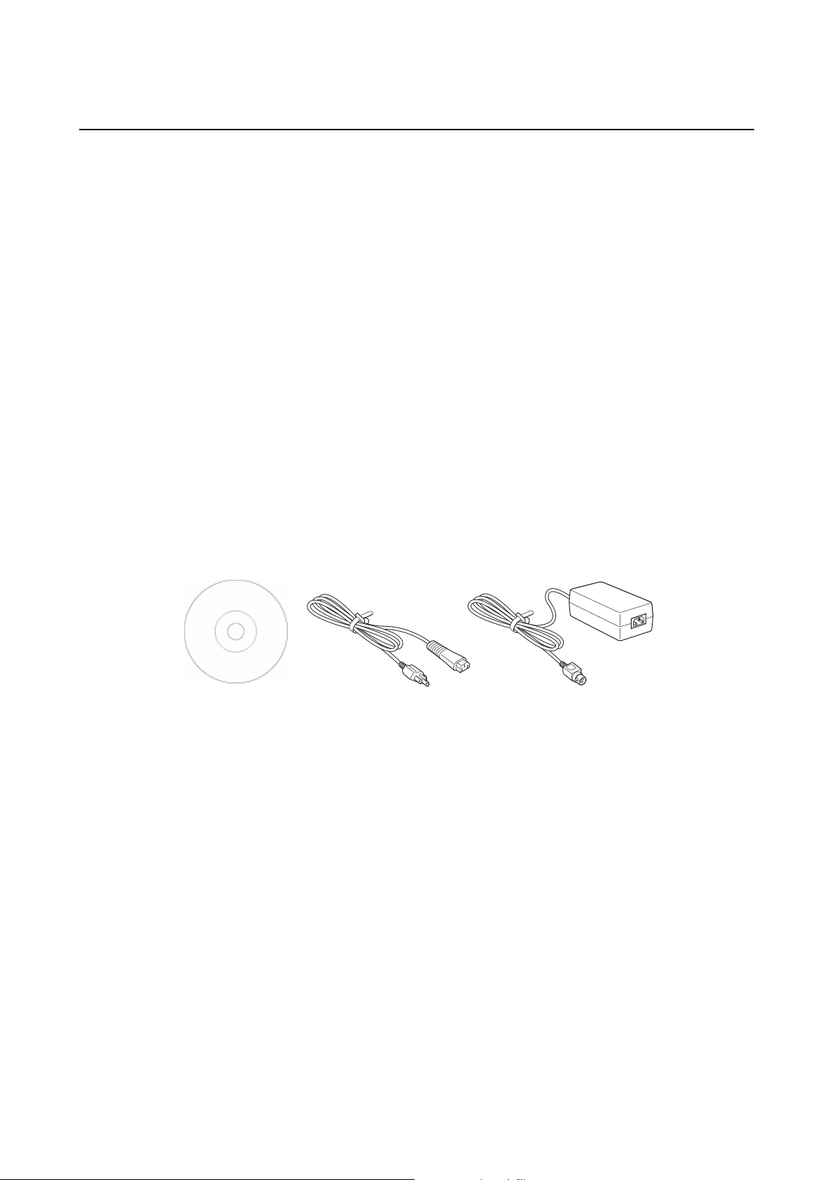
1.2.1 Included Accessories
After unpacking the printer, verify that you have the following materials:
User Documents
(DVD)
The shape of the power plug may vary, depending on the location where it was purchased.
Power plug*
AC adapter
Page 1-2 LD610 User’s Technical Reference
Page 11
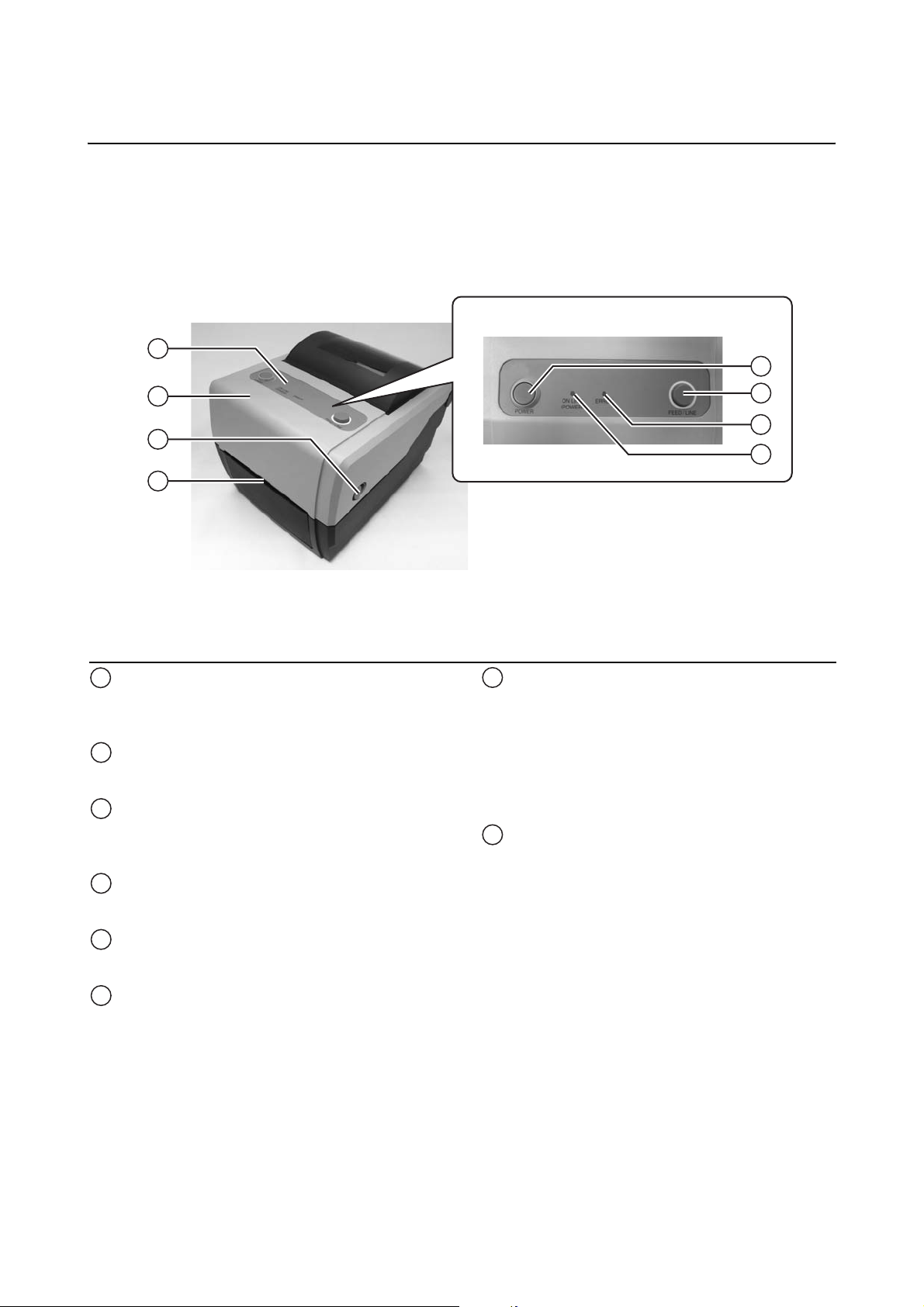
1.3 PARTS IDENTIFICATION
Front view
1
Section 1: Introduction
5
2
3
4
Operator panel
1
It consists of two contact buttons and two
LED indicators (green and red).
Top cover
2
Open this cover to load the media and ribbon.
Cover open/close latch
3
Pull these latches on both sides of the printer
forward to open the Top cover of the printer.
Media ejection slot
4
Opening for media output.
POWER button
5
Press this button to turn the power on or off.
6
7
8
ERROR LED indicator
7
The LED lights or blinks red when an error is
detected in the printer.
During printer configuration setting, the
ERROR indicator responses in conjunction
with the ON LINE (POWER) indicator to show
the modes of the printer.
ON LINE (POWER) LED indicator
8
The LED lights green when the printer is onlin e
and blinks green when the printer is offline.
During printer configuration setting, the ON
LINE (POWER) indicator responses in
conjunction with the ERROR indicator to show
the modes of the printer.
FEED/LINE button
6
Press this button to select the printer status
(online/ offline) or to feed the media.
LD610 User’s Technical Reference Page 1-3
Page 12

Section 1: Introduction
1.3 PARTS IDENTIFICATION (cont’d)
Back view
9
USB and RS232C interface on-board
10
11
12
USB and LAN interface on-board
10
11
13
Media inlet
9
An opening for Fan-folded media or media
from unwinder to feed in to the printer.
DC input power terminal
10
Supplies power to the printer by inserting the
power cable via the AC adapter.
USB interface terminal
11
To connect printer to the host computer using
the USB interface.
USB and IEEE interface on-board
LAN interface terminal
13
To connect printer to the host computer using
LAN interface.
IEEE interface terminal
14
To connect printer to the host computer using
IEEE interface.
10
14
11
RS-232C interface terminal
12
To connect printer to the host computer using
RS-232C interface.
Or, to connect the optional Keypad, Scanner or
Smart keyboard to the printer.
Page 1-4 LD610 User’s Technical Reference
Page 13
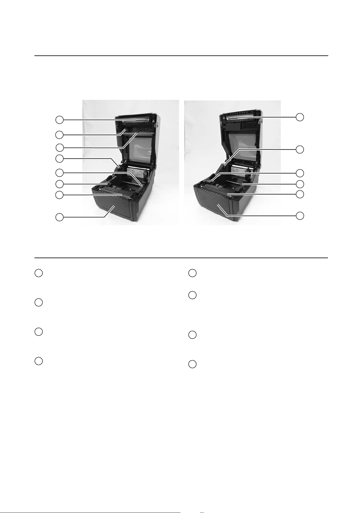
1.2 PARTS IDENTIFICATION (cont’d)
Internal view when Top cover is opened
Section 1: Introduction
15
16
17
18
19
20
21
22
LD610 T LD610 D
Print head
15
This component is used to print on the media.
Perform maintenance at regular intervals.
Ribbon unit
16
Used to load the ribbon and wind up the used
ribbon.
Pull out lever
17
This is used to pull out the ribbon unit from the
top cover for ribbon loading.
Roll media holder
18
To hold the roll media.
CG408DT/ CG412DTCG408TT/ CG412TT
Media guide slide lever
19
Set to meet the size of the media used.
Media guide and I-Mark/ Gap sensor
20
A guide for the media to feed properly.
Detects the I-Mark on the media or gap of the
label.
Platen roller
21
This roller feeds the media. Perform
maintenance at regular intervals.
Optional device compartment
22
Used to install optional cutter or dispenser unit.
15
18
20
19
21
22
LD610 User’s Technical Reference Page 1-5
Page 14

Section 1: Introduction
This page is intentionally left blank
Page 1-6 LD610 User’s Technical Reference
Page 15

Section 2: Installation
INSTALLATION
This section assists you in installing consumable media in the printer, as well as adjustment instructions and
installing other optional attachment units.
The following information is provided:
• 2.1 Site Location
• 2.2 Media Selection
• 2.3 Loading Labels
• 2.4 Loading the Carbon Ribbon (For LD610 T only)
• 2.5 Connections
LD610 User’s Technical Reference Page 2-1
Page 16
Section 2: Installation
2.1 SITE LOCATION
Consider the following when setting up the printer:
• Place the printer on a solid flat surface with adequate space. Make sure there is enough space above
the printer to provide clearance for the top cover to swing open.
• Place it away from hazardous materials or dusty environments.
• Place it within operational distance of the host comp uter, within interface cable specifications.
2.2 MEDIA SELECTION
The size and type of the labels or paper to be printed sho uld have been taken into consideratio n before printer
purchase. Ideally, the media width will be equal to, or just narrower than, the print head. Using media that
does not cover the print head will allow the platen roller to tread on it and wear it out. The media edge will also
wear a groove in the platen roller, which can affect print quality.
Note:
For optimal print performance and durability, please use OKI-certified label and ribbon supplies on
this printer. Using supplies not tested and approved for use by OKI can result in unne cessary wear and
damage to vital parts of the printer, and may void the warranty.
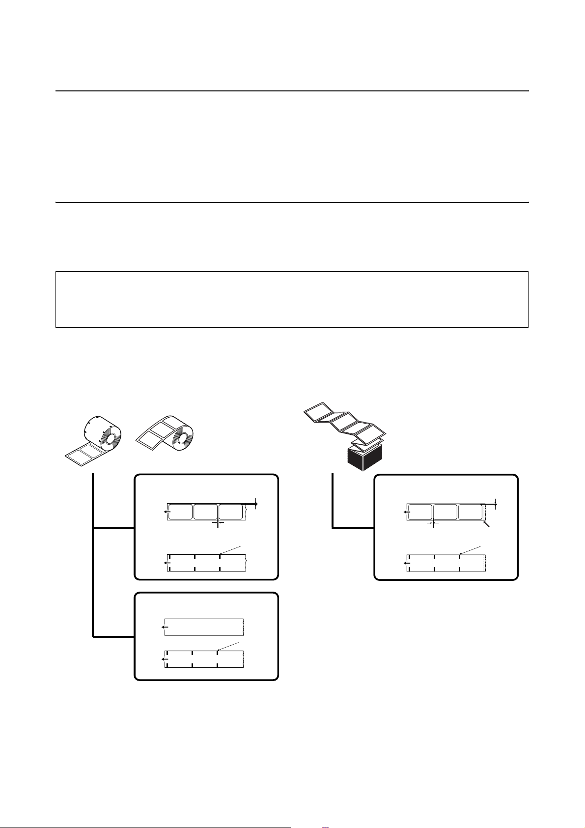
This printer can print on roll media or fan-folded media. The methods used for loading roll media and fanfolded media differ. The printer uses sensors to detect I-Marks or gap on the media in order to precisely
position the print content.
Face-in Roll media Face-out Roll media
Front side
Paper feed direction
Label gap/
I-Mark
Reverse side
Front side
Paper feed direction
l-Mark
paper
Reverse side
3 mm
Gap (spacing)
1.5 mm
I-Mark
I-Mark
Fan-fold media
Label gap/
I-Mark
Front side
Paper feed direction
Gap (spacing)
Reverse side
3 mm
1.5 mm
Fold perforation
I-Mark
Page 2-2 LD610 User’s Technical Reference
Page 17

2.3 LOADING LABELS
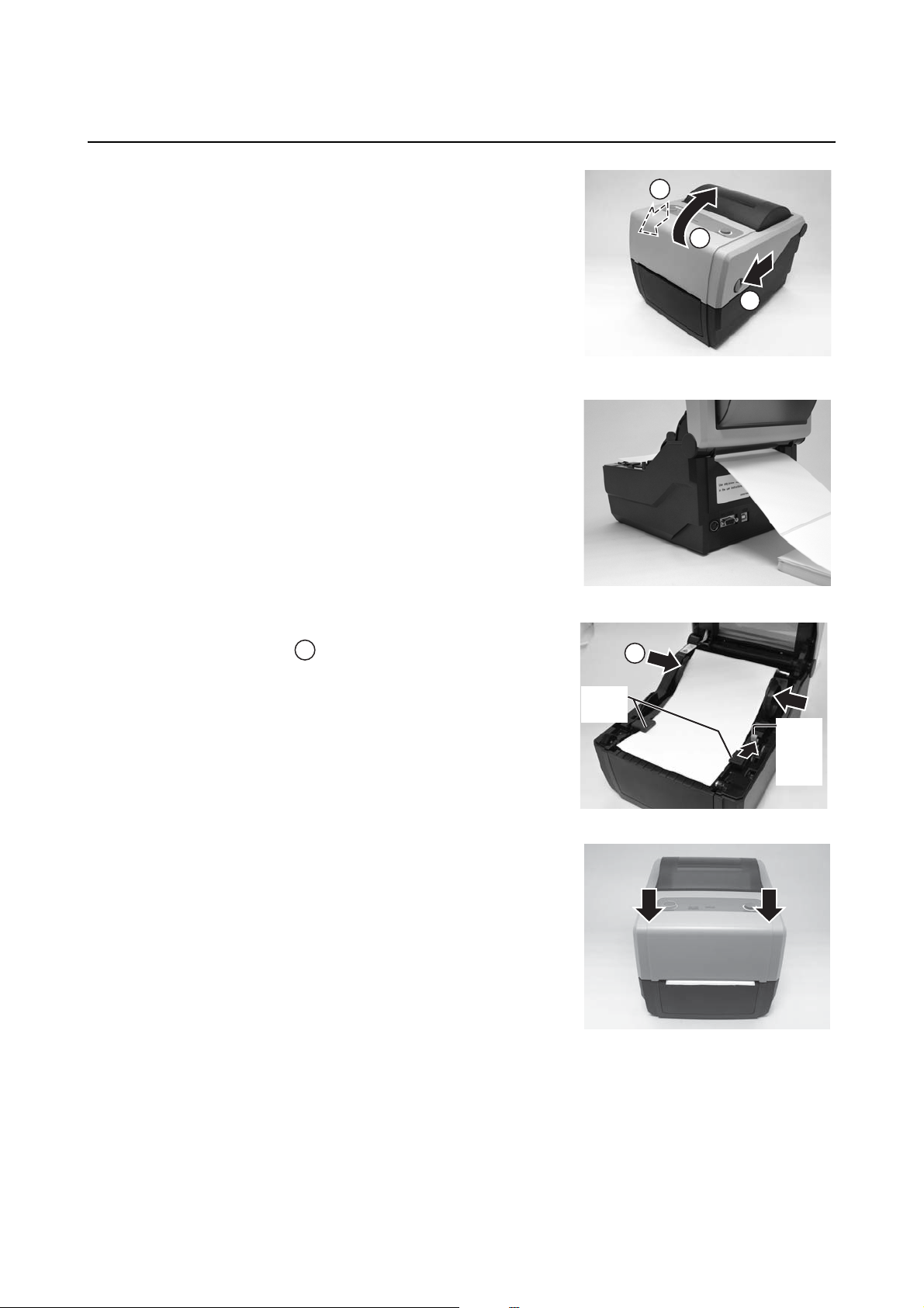
2.3.1 Loading Roll media
With the power supply off, pull the cover open/close
1.
latches on both sides of the printer toward you to
unlock the top cover, and then open the top cover .
Note:
Make sure that the cover rests firmly so that it will not fall
forward and injure your hands.
2. While holding the media guide slide lever, adjus t the
width of the media holder to match the media size.
1
1
Section 2: Installation
1
2
1
2
1
3. Load the media onto the media holder.
4. After pulling out the media, pass the media through the
media guides and place the leading edge of the media
on top of the platen roller.
Note:
Make sure the printed side of the media is facing
upwards.
Media guide
slide lever
Media guides
Printed side should face
upwards
LD610 User’s Technical Reference Page 2-3
Page 18

Section 2: Installation
2.3 LOADING LABELS (cont’d)
Close the top cover until it clicks into position.
5.
Notes:
• Be careful not to get your fingers pinched while
closing the top cover.
• If the optional cutter or dispenser has been
purchased, see Section 8.1 Optional Accessories -
Cutter and Section 8.2 Optional Accessories -
Dispenser on how to route the media.
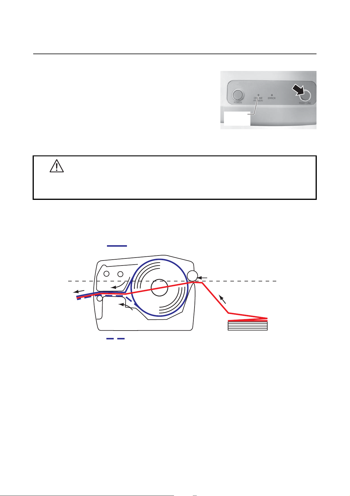
6. After loading the media, turn on the power.
The printer is online and the ON LINE (POWER)
indicator lights green.
When the printer is ready, press the FEED/LINE button
to output the leading part of the media.
ON LINE
(POWER)
Caution
• When replacing media, bear in mind that the print head and its surrounding area remain hot.
Keep your fingers away from these areas to prevent injury.
• Avoid touching even the edge of the print head with your bare hands.
Page 2-4 LD610 User’s Technical Reference
Page 19
2.3 LOADING LABELS (cont’d)
2.3.2 Loading Fan-folded media
1.
With the power supply off, pull the cover open/close
latches on both sides of the printer toward you to unlock
the top cover, and then open the top cover.
Note:
Make sure that the cover rests firmly so that it will not fall
forward and injure your hands.
2. Pass the fan-folded media through the opened window
at the rear of the unit.
Note:
Make sure the printed side of the media is facing
upwards.
Section 2: Installation
1
2
1
3. While holding the media guide slide lever, adjust the
width of the media holder to match the media size.
After pulling out the media, pass the media through the
media guides and place the leading edge of the media
on top of the platen roller.
1
4. Close the top cover until it clicks into position.
Notes:
• Be careful not to get your fingers pinched while
closing the top cover.
• If the optional cutter or dispenser has been
purchased, see Section 8.1 Optional Accessories -
Cutter and Section 8.2 Optional Accessories -
Dispenser on how to route the media.
1
Media
guides
Media
holder
slide
lever
LD610 User’s Technical Reference Page 2-5
Page 20
Section 2: Installation
2.3 LOADING LABELS (cont’d)
After loading the media, turn on the power.
5.
The printer is online and the ON LINE (POWER) LED
lights green.
When the printer is ready, press the FEED/LINE button
to output the leading part of the media.
ON LINE
(POWER)
Caution
• When replacing media, bear in mind that the print head and its surrounding area remain hot.
Keep your fingers away from these areas to prevent injury.
• Avoid touching even the edge of the print head with your bare hands.
2.3.3 Overview of the Roll media and Fan-folded media loading path
Roll media (Face-out)
Roll media (Face-in)
Fan-fold media
(Printed side face up)
Page 2-6 LD610 User’s Technical Reference
Page 21
Section 2: Installation
2.4 LOADING THE CARBON RIBBON (FOR LD610 T ONLY)
The LD610 T printer enables two types of printing, Thermal transfer and Direct thermal. Thermal transfer
paper media requires the use of carbon ribbon for print application. In such a scenario, it is the carbon ribbon
that contains the ink that will be transferred to the media. Direct thermal paper media has a coating on the
surface that is made visible through the application of heat from the print head. In this case, there is no need
of loading the carbon ribbon.
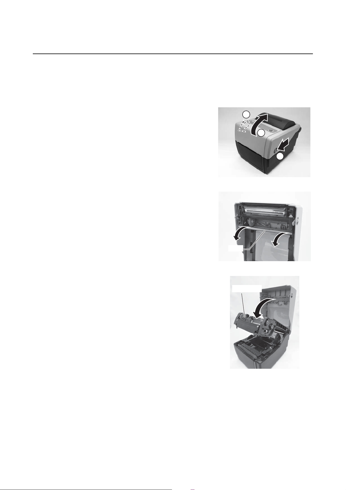
1. With the power supply off, pull the cover open/close
latches on both sides of the printer toward you to unlock
the top cover, and then open the top cover.
Note:
Make sure that the cover rests firmly so that it will not fall
forward and injure your hands.
2. Pull the lever on the middle of the ribbon unit
downward to pull out the ribbon unit.
Then simply let down the ribbon unit. There is a stopper
midway through its movement range that will prevent the
ribbon unit from snapping down.
1
2
1
Lever
Ribbon unit
LD610 User’s Technical Reference Page 2-7
Page 22
Section 2: Installation
2.4 LOADING THE CARBON RIBBON (FOR LD610 T ONLY) (cont’d)
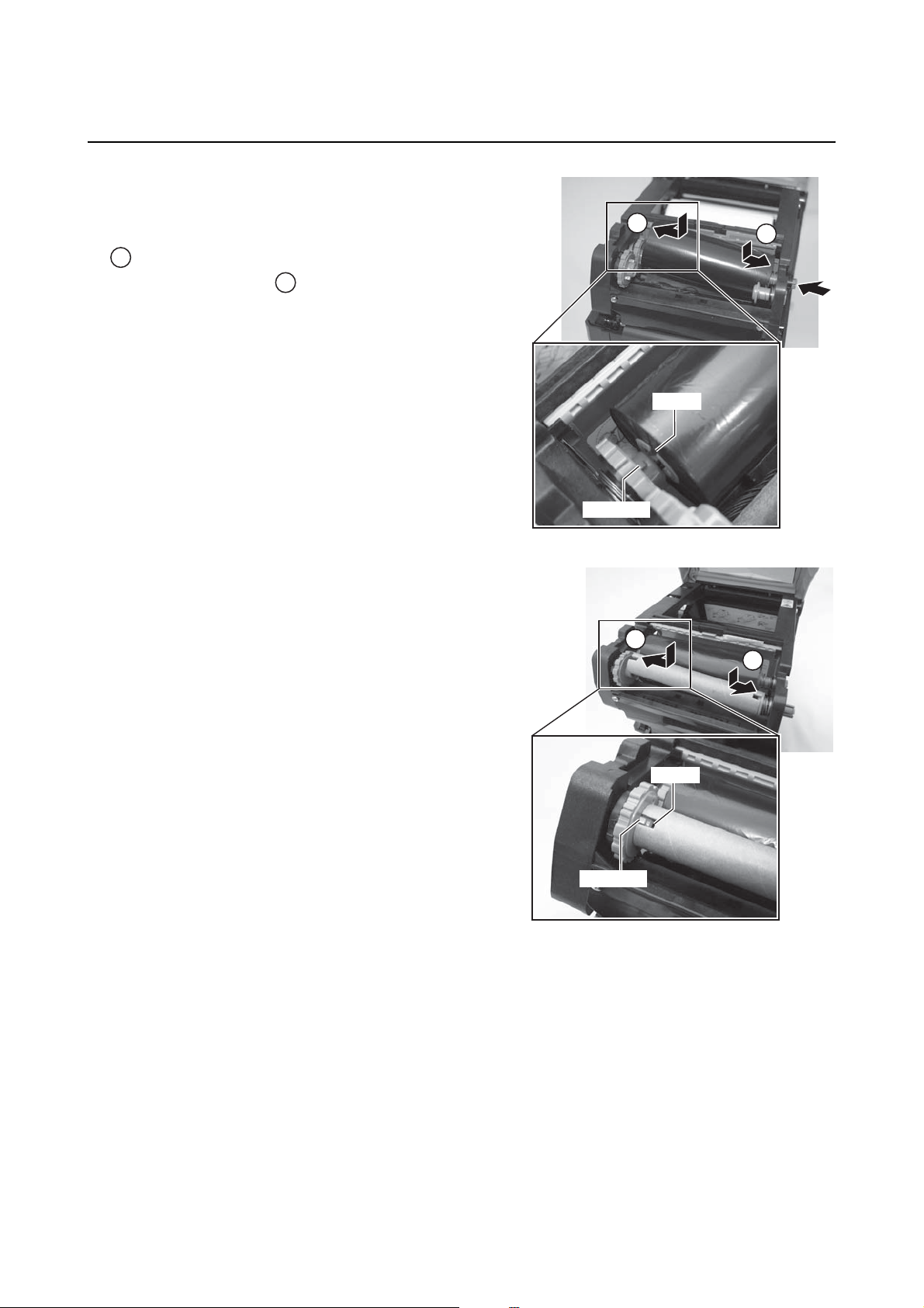
Open the carbon ribbon package, and then load the
3.
ribbon in the ribbon supply unit.
With the ribbon winding in clockwise direction, push in
the ribbon roll to the right side of the ribbon supply unit
. Then fix the other side of the ribbon roll to the left of
1
the ribbon supply unit . T urn the ribbon roll until the
core snaps on the protrusion of the left ribbon supply
unit.
Note:
Use only genuine OKI carbon ribbons for maximum print
quality and printer durability.
2
protrusion
2
1
groove
4. Mount the empty ribbon core on the ribbon wind-up
unit the same manner as in step 3 above.
When loading the carbon ribbon for the first time, use the
empty ribbon core supplied with the printer. However,
the subsequent ribbon core can be obtained from the
last used up ribbon roll.
2
1
groove
protrusion
Page 2-8 LD610 User’s Technical Reference
Page 23
2.4 LOADING THE CARBON RIBBON (FOR LD610 T ONLY) (cont’d)
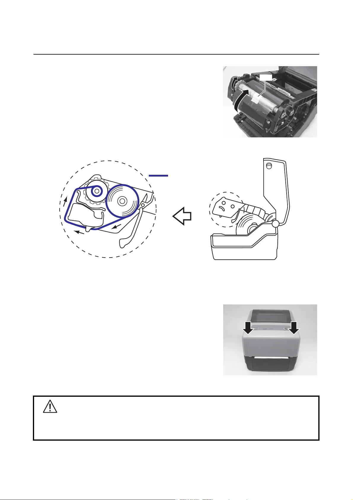
From the ribbon supply unit, pass the carbon ribbon
5.
underneath the print head assembly to the ribbon
wind-up unit.
Affix the carbon ribbon to the ribbon core us ing adhesive
tape, and wind it up several times in the d ire ction shown
by the turn arrow.
Confirm that the ribbon has been loaded as shown in the
figure below or as illustrated on the inner side of the top
cover.
5LEERQURXWH
Section 2: Installation
tape
Note:
The dull side (ink side) of the ribbon should be facing outward as it travels through the print head
assembly.
6. Close the top cover until it clicks into position.
Note:
• Be careful not to get your fingers pinched while
closing the top cover.
7. After loading the media and the carbon ribbon, do a test
print to check that the media roll and ribbon have been
loaded properly. See Section 3.3 User Test Print Mode
for instructions on how to run test print.
Caution
• When replacing carbon ribbon, bear in mind that the print head and it s surround ing area remain hot.
Keep your fingers away from these areas to prevent injury.
• Avoid touching even the edge of the print head with your bare hands.
LD610 User’s Technical Reference Page 2-9
Page 24
Section 2: Installation
2.5 CONNECTIONS
This section explains the power cable and interface cable connection procedures.
2.5.1 Standard interface connection
LD610 Series printers have three types of Main PCBs, and each type of PCB is equipped with different types
of interface to perform data communication with the host. These are described as follows.
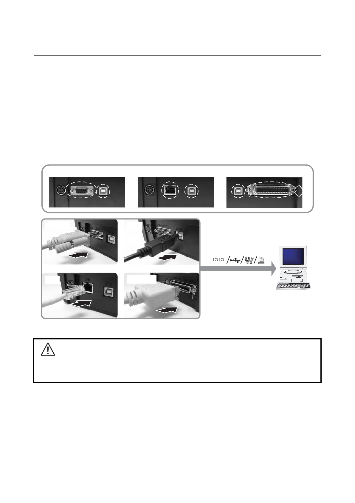
1) RS232C and USB interface on-board
2) LAN and USB interface on-board
3) USB and IEEE 1284 interface on-board
Connect only one type of interface cable from the printer to the host computer. Use the cable that is
compatible with the standard of the interface board as stated in Section 7: Interface Specifications. Make
sure the cable is correctly oriented.
RS232C and USB interface on-board
RS232C
LAN
LAN and USB interface on-board USB and IEEE 1284 interface on-board
USB
Host
IEEE 1284
Caution
Never connect or disconnect interface cables (or use a switch bo x) with power ap plied to either the host
or printer. This may caused damage to the interface circuitry in the printer/ host and is not covered by
warranty.
Page 2-10 LD610 User’s Technical Reference
Page 25
Section 2: Installation
2.5 CONNECTIONS (cont’d)
2.5.2 To activate the connected interface
After connection, you need to configure the printer to operate on the connected interface.
1. Please perform the procedures to set the appropriate interface mode as describe in Section 3.5
Operation Setting Mode.
2. In step 3 of this procedure, briefly press the FEED/LINE button repeatedly to select the interface mode
according to your connection.
Connected Interface USB RS-232C LAN IEEE 1284
ON LINE (POWER)
indications
ERROR
indications
Blinks in green
Blinks in red
flashes green in a long interval
Off
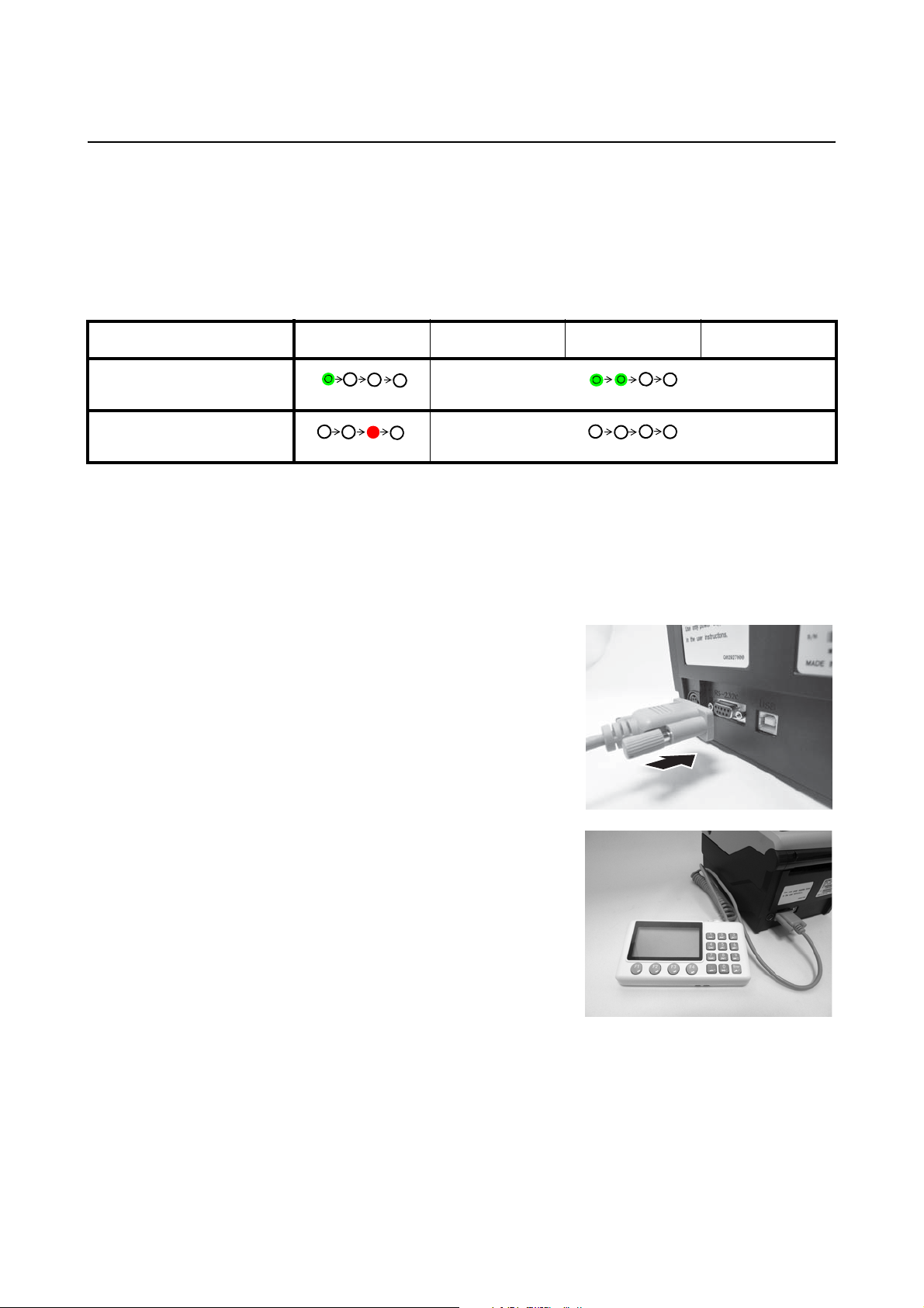
2.5.3 Connecting the optional keypad/Scanner/Smart keyboard
The optional keypad, scanner or smart keyboard can be conn ected to th e LD610 Ser ies printer with RS-2 32C
interface terminal, thus providing a stand-alone function. This function offers advanced features of Format
Registration or Call Function without connecting to a host computer . You can use either Label Gallery or SBPL
commands for the format registration. As for the data required for call function, capture it as a barcode with a
scanner connected with LD610 Series printer.
1. Make sure that power cable is not connected to the
printer.
2. Connect the cable from the optional device to the
RS232C terminal at the back of the printer.
Note:
Make sure the connector is correctly oriented. Secure
the printer with one hand, and insert the connector firmly.
3. Set the printer for use with the connected device. Refer
to Section 3.5 Operation Setting Mode and perform
the procedures to set the printer to Keypad mode or
Scanner/ Smart keyboard mode accordingly.
In step 3 of this procedure, briefly press of the FEED/
LINE button repeatedly until the respective lighting
sequence of the ON LINE (POWER) and ERROR indicator is displayed.
Notes:
•If Keypad or Scanner/Smart keyboard mode is
selected, even if the device is not connected, other interfaces cannot be activated.
• Only compatible scanner, compatible smart keyboard
and OKI keypad can be connected to LD610 Series
printer. Refer to OKI sales representative for more
details.
An example of optional keypad
connection to the printer.
LD610 User’s Technical Reference Page 2-11
Page 26

Section 2: Installation
2.5 CONNECTIONS (cont’d)
2.5.4 Connecting the Power Cable
Warning
• Be sure to connect the ground wire. Failure to do so may cause an electric shock.
• Do not operate the power switch or insert/remove the power cable while your hands are wet.
Doing so may cause an electric shock.
Caution
The power cable and the AC adapter provided with this printer are for use with this printer only.
They cannot be used with other electrical devices.
1.
Connect the AC power cable to the AC adapter.
AC adapter
2. Connect the DC power plug from the AC adapter to the
DC input power terminal on the back of the printer.
Make sure the flat side of the DC power plug is facing
right. Secure the printer with one hand, and insert the
cable firmly.
3. Insert the AC power plug into a AC power outlet.
Make sure that the AC voltage of your region is within
the range of AC 100 to 240V, 50/60 Hz.
A 3-pin plug is attached to the power cord provided with
your printer. One of these pins is the ground wire.
You must use a 3-pin power outlet. The plug will not
work with a 2-pin power outlet.
AC power
plug
Flat side faces right.
DC input power
terminal
* The shape of the power plug may vary depending on
the location where the printer was purchased.
Page 2-12 LD610 User’s Technical Reference
Page 27
2.5 CONNECTIONS (cont’d)
2.5.5 Turning On the Power
Warning
Do not operate the power switch or insert/remov e the
power cable while your hands are wet. Doing so may
cause an electric shock.
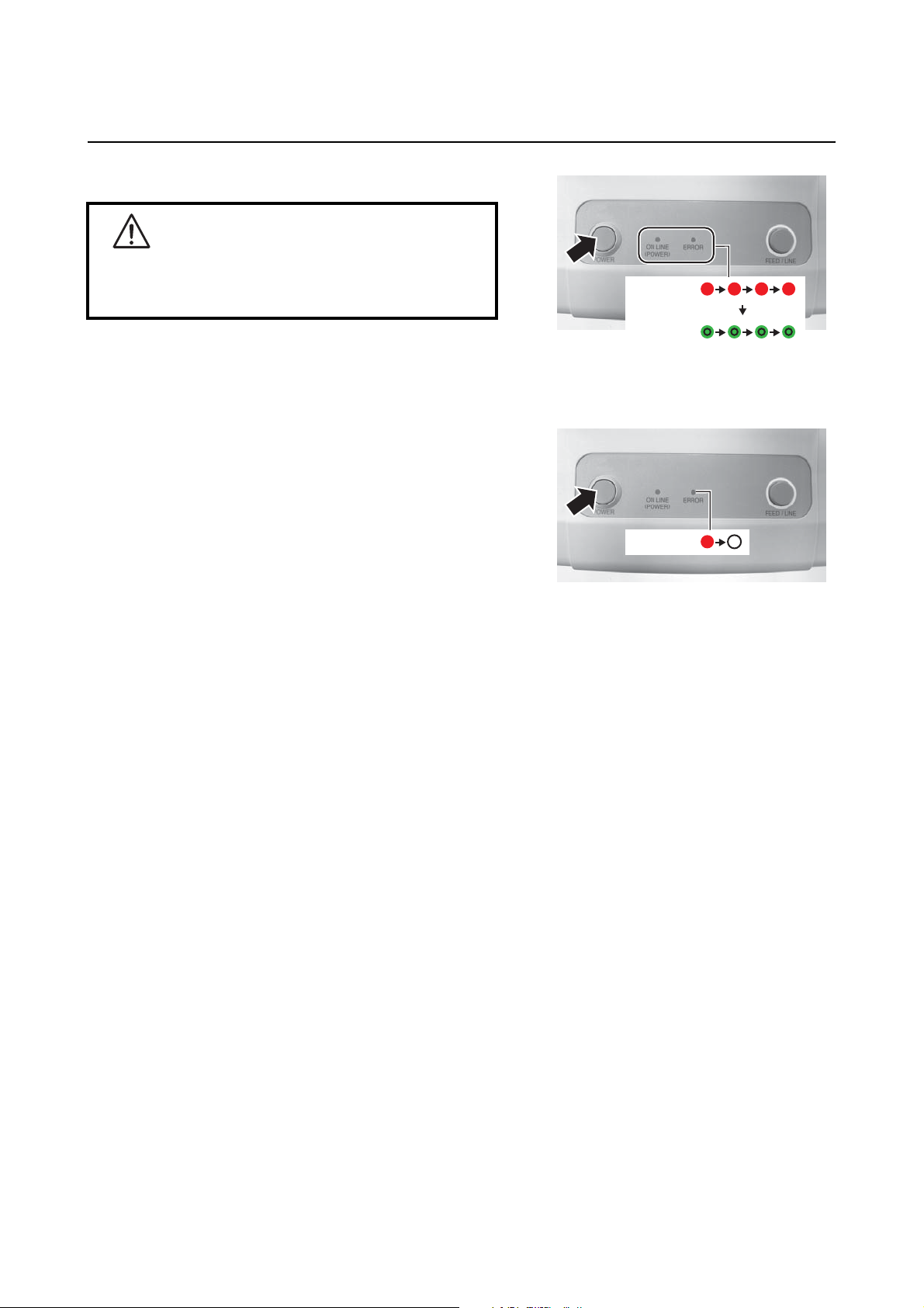
Press the POWER on the operation panel of the unit.
The ERROR indicator displays red, then after a single beep
sound, the ON LINE (POWER) indicator displays green.
2.5.6 Turning Off the Power
When you have completed the printing job, turn the printer
off.
Be sure to confirm that the printer is in the offline status .
Press and hold the POWER button until the ERROR
indicator displays red and then turns off.
If there is any printed paper remaining in the printer,
cut it off.
ERROR
ON LINE
(POWER)
ERROR
Section 2: Installation
Beep
sound
LD610 User’s Technical Reference Page 2-13
Page 28

Section 2: Installation
This page is intentionally left blank
Page 2-14 LD610 User’s Technical Reference
Page 29

Section 3: Operation and Configuration
OPERATION AND CONFIGURATION
Before using the printer, it is best to read this manual thoroughly. Otherwise, you may disturb default settings
on which the instructional procedures in this manual are based.
Most of the printer’s settings are controlled via standard SBPL commands or by using the provided OKI
Utilities Tool application.
Some printer settings may be manually configured via the POWER and FEED/LINE buttons with the ON LINE
(POWER) indicator and ERROR indicator on the front of printer. All of the printer’s buttons are used either
singularly, or together, to perform configuration activities. The instructions to these operations are described
in this section.
LD610 User’s Technical Reference Page 3-1
Page 30
Section 3: Operation and Configuration
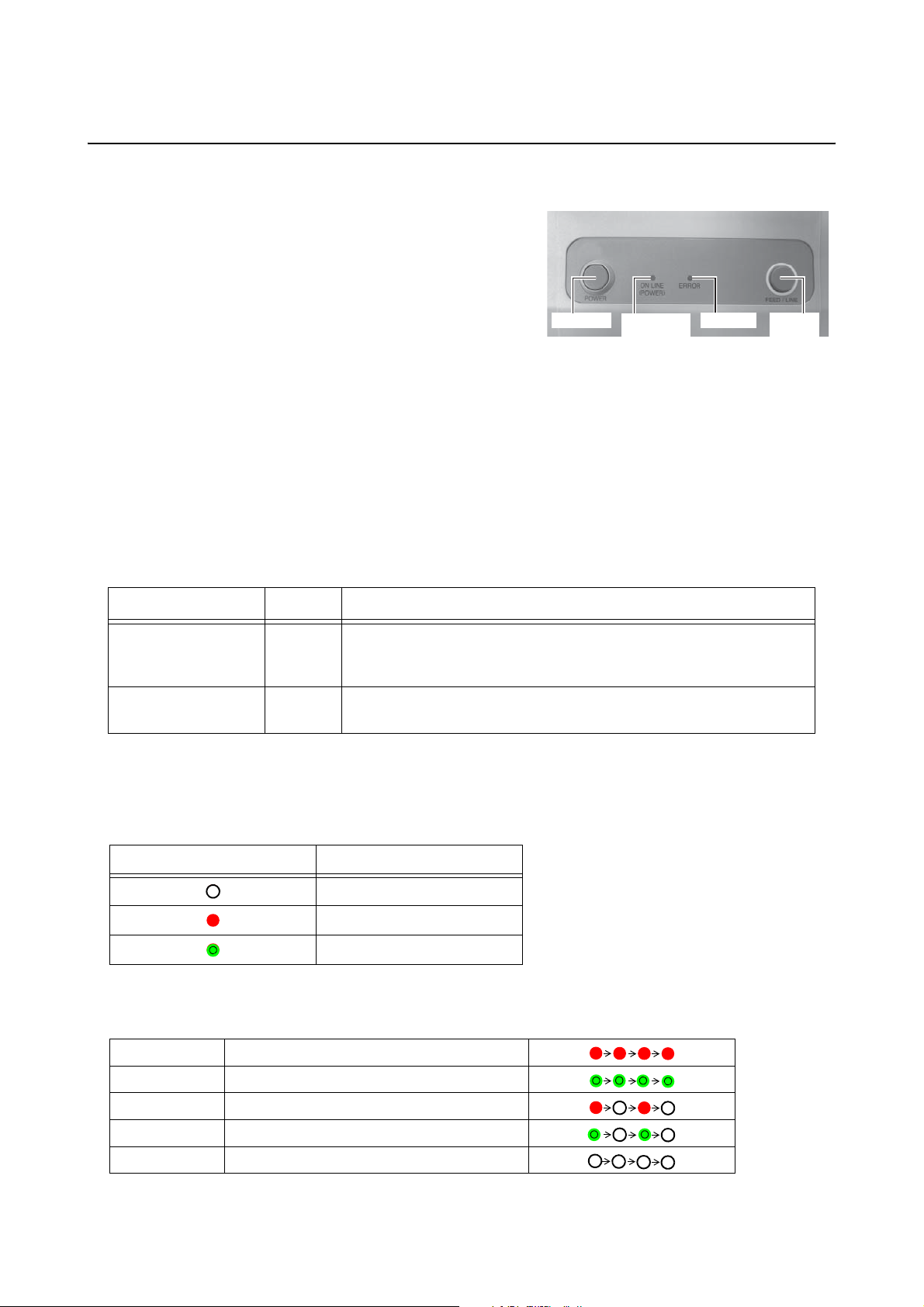
3.1 OPERATOR PANEL
The operator panel located on the top front, consists of two buttons and two LED indicators (red and green).
• POWER button
Press POWER button to turn on or off the printer.
Press POWER button together with FEED/LINE button
to enter various operating modes.
• FEED/LINE button
•Press FEED/LINE button during normal print
operation to pause the printing and set the printer to
offline mode. Press again to toggle the printer
between the online and offline mode.
• When printer idles in online mode, press the FEED/
LINE button to feed a blank label.
• During label feed, press the FEED/LINE button to
pause label feed and go offline.
• The printer will go offline after opening and closing
the top cover. Press the FEED/LINE button to make
the printer go online.
POWER
ON LINE
(POWER)
ERROR
FEED/
LINE
• ON LINE (POWER) and ERROR indicators
When the printer is in normal mode, this two indicators notifies the user of various status conditions:
LED Indicator Color Functions
ON LINE (POWER) Green Illuminates when printer is ready to receive data or is in printing
mode (Online).
Blinks when the printer is in offline mode.
ERROR Red Illuminates or blinks when there is a system fault, for example,
paper end.
During different operation modes, the ON LINE (POWER) and ERROR indicators turn on and flash
differently.
In this section, the combination of the following symbols has been used to describe the indicator lighting
sequence. Refer to the example listed below for lighting sequences.
Indicator symbol Status
Off
Red light
Green light
The repeating patterns are as shown in the below examples. The sequences are indicated as from left to
right. One LED Indication flash is approximately 200ms, and two indication flashes in a row are for about
400ms.
Example 1 Indicator: Red light.
Example 2 Indicator: Green light.
Example 3 Indicator: Blinking red light.
Example 4 Indicator: Blinking green light.
Example 5 Indicator: off
Page 3-2 LD610 User’s Technical Reference
Page 31

Section 3: Operation and Configuration
3.2 OPERATING MODES
You can set the printer in any of the following modes:
1. Normal mode (including Online/Offline modes)
2. User Test print mode
3. Factory Test print mode
4. Operation Setting mode:
• Program download mode
• Font download mode
• Default setting mode
• HEX Dump mode
• USB interface
• RS-232C/ LAN/ IEEE 1284 interface
• Keypad selection
• Scanner, Smart keyboard
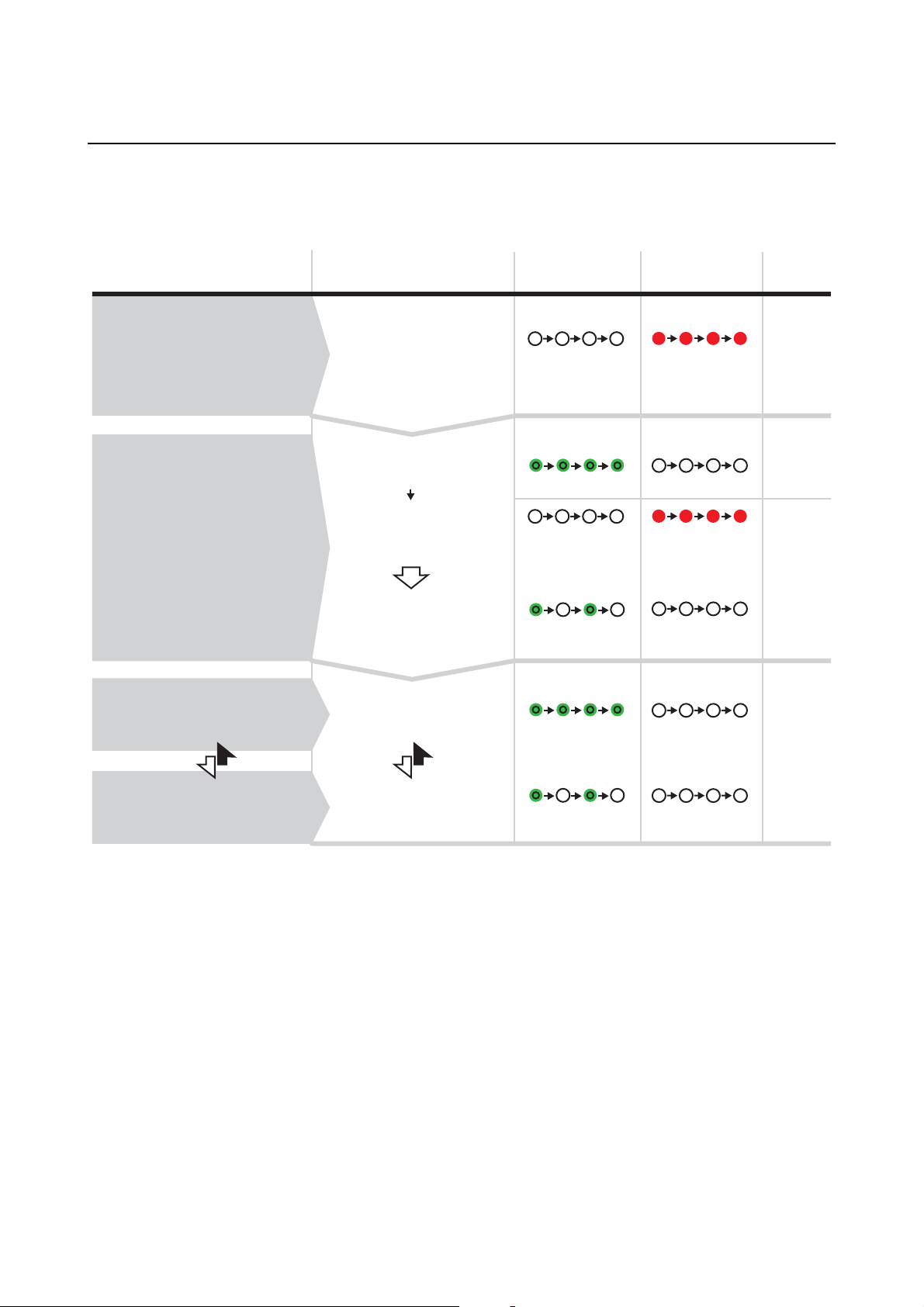
You can access the modes by pressing and releasing the POWER button and the FEED/LINE button at
particular points during the ON LINE (POWER) and ERROR indicators’ lighting sequence.
The following flow chart provides a clear summary of each of the modes and its access method.
LED indicator responses
Procedures
Power off
Press POWER
button
While pressing
FEED/LINE button,
press POWER button
Operating Mode ON LINE (POWER) ERROR
Printer Start up
Normal Mode
(Online)
Release POWER button and
keep holding FEED/LINE
button until the desired mode
lighting pattern is shown.
Printer Start up
User Test Print
Mode
Holding
FEED/LINE
button
Off
Green light
Off
Green light
Red light
Off
Red light
Off
Buzzer
One short beep
One
short beep
Two
short beeps
Three
short beeps
LED indicator symbols
: Off
: Red light
: Green light
Factory Test
Print Mode
Holding
FEED/LINE
button
Operation setting
Mode
Holding
FEED/LINE
button
Off
Blinking green light
Red light
Off
LD610 User’s Technical Reference Page 3-3
Page 32

Section 3: Operation and Configuration
3.3 USER TEST PRINT MODE
This mode produces test labels for diagnostic purposes.
Preparation:
Make sure the media or ribbon (if required) are properly loaded in the printer.
While pressing
1
FEED/LINE button, press
and release POWER
button. Keep holding
FEED/LINE button.
Release FEED/LINE
2
button when ON LINE
(POWER) indicator
changes to green light
and single short beep
sound is heard.
(The printer will cyclically
advance to next mode as
long as the FEED/LINE
button is held down.)
Press FEED/LINE button
3
to start test printing.
Printer statusProcedures
Printer start-up
User Test Print mode.
FEED/LINE
released
User Test Print mode
is activated and then
paused.
User Test Print start
and print continuously.
ON LINE (POWER)
indicator
Off
Green light
Blinking green light
Green light
ERROR
indicator
Red light
Off
Off
Off
Buzzer
One short
beep
Press FEED/LINE button
to pause the test printing.
Press again to resume.
User Test Print paused.
Blinking green light
Off
Notes:
• If you missed the chance to release the FEED/LINE button in step 2 above, just keep holding the
FEED/LINE button and wait for the next cycle.
• If you released the FEED/LINE button at the wrong ON LINE (POWER) or ERROR indicators, just turn off
the power and restart the procedure.
• The printer will continuously print the user test labels until the FEED/LINE button is pressed. The printing is
paused and will resume printing if the FEED/LINE button is press again.
To terminate the User Test Print mode
First, ensure that you have pressed the FEED/LINE button to pause the test printing, then press POWER to
turn off the printer.
Page 3-4 LD610 User’s Technical Reference
Page 33

Section 3: Operation and Configuration
3.3 USER TEST PRINT MODE (cont’d)
3.3.1 Output Data of the User Test Print
The output data of the User Test Print shows the current settings of the printer.
These output data are printed in three parts, each with the printing area of 110mm [4.33”] (Width) x 115mm
[4.53”] (Pitch), Standard.
First print-out (Settings)
No. Print Item Contents of the print data
1 Model Printer model name LD610 T (*), LD610 D
*: “T” is printed for thermal
transfer print.
“D” is printed for direct
thermal print.
2 Offset Offset value (Vertical and
horizontal directions)
3 Pitch Offset Pitch offset value ±099 DOT
4 Cut Offset Cut position offset value ±099 DOT
5 Peel Offset Peel off position offset value ±099 DOT
6 Tear Off Offset Tear off position offset value ±099 DOT
7 Label Size Label size (Pitch/Width) (P)**** x (W)*** DOT
8 Print Speed Print speed 50mm/s
9 Print Darkness Print darkness 1A~5A
10 Operation mode Operation mode CUT/ NONE SEPA/
11 Sensor Type Sensor type Gap
12 Paper End Search Paper end detection method TAG/ ROLL
13 Zero Slash Zero slash ON/ OFF
(H)±300 (V)±300 DOT
75mm/s
100mm/s
TEAR OFF/ DISPENSER/
CONTINUOUS
I-Mark
None
14 Proportional Pitch Proportional pitch ON/ OFF
15 Buzzer Buzzer ON/OFF
16 Initial Feed Initial feed ON/ OFF
17 Protocol-codes Protocol code setting value
(Standard / Nonstandard)
18 Option waiting time Option waiting time 500 to 20000 ms
19 Num of formats stored Number of formats stored *
20 Printer mode Printer mode ONLINE/ STANDALONE
LD610 User’s Technical Reference Page 3-5
Nonstandard/ Standard
Page 34

Section 3: Operation and Configuration
3.3 USER TEST PRINT MODE (cont’d)
Second print-out (Protocol code setting values)
No. Print Item
1STX
2ETX
3 ESC
4ENQ
5CAN
6 NULL
7 OFFLINE
8 AUTO ONLINE
9 ZERO SLASH Zero slash
10 EURO Euro code
Third print-out (Interface)
USB and RS-232C interface on board
No. Print Item Contents of the print data
1 Selected Interface In-use interface USB / RS-232C / Keypad /
Scanner
2 Interface 1 Interface 1 USB
3 Buffer Type Buffer type Multi
4 Protocol Protocol Driver
5 Serial No. Serial No. Serial No./ None
6 Interface 2 Interface 2 RS-232C
Communication parameters (19200.8.N.1)
Baud rate (bps)
9600, 19200, 384000
Data length (bit)
8, 7
Parity
N, O, E
Stop bit (bit)
1 2
7 Buffer Type Buffer type 1 item / Multi
8 Protocol Protocol ER/RS
XON/XOF
Driver
Status3
Page 3-6 LD610 User’s Technical Reference
Page 35

Section 3: Operation and Configuration
3.3 USER TEST PRINT MODE (cont’d)
USB and IEEE 1284 interface on board
No. Print Item Contents of the print data
1 Selected Interface In-use interface USB / IEEE1284
2 Interface 1 Interface 1 USB
3 Buffer Type Buffer type Multi
4 Protocol Protocol Driver
5 Serial No. Serial No. Serial No./ None
6 Interface 2 Interface 2 IEEE1284
7 Buffer Type Buffer type Multi / 1 item
8 Protocol Protocol Driver
USB and LAN interface on board
No. Print Item Contents of the print data
1 Selected Interface In-use interface USB / LAN
2 Interface 1 Interface 1 USB
3 Buffer Type Buffer type Multi
4 Protocol Protocol Driver
5 Serial No. Serial No. Serial No./ None
6 Interface 2 Interface 2 LAN
7 Buffer Type Buffer type Multi
8 Protocol Protocol Driver(CYC)
Driver(ENQ)
Status3
9 MAC Address MAC address **:**:**:**:**:**
10 IP Address IP address 000.000.000.000
~ 255.255.255.255
11 Subnet Mask Subnet mask 000.000.000.000
~ 255.255.255.255
12 Default Gateway Default gateway 000.000.000.000
~ 255.255.255.255
13 DHCP DHCP Enable / Disable
14 RARP RARP Enable / Disable
LD610 User’s Technical Reference Page 3-7
Page 36
Section 3: Operation and Configuration
3.4 FACTORY TEST PRINT MODE
This mode produces test labels for diagnostic purposes.
Preparation:
Make sure the media or ribbon (if required) are properly loaded in the printer.
While pressing
1
FEED/LINE button, press
and release POWER
button. Keep holding
FEED/LINE button.
Release FEED/LINE
2
button when ERROR
indicator changes to red
light and two short beeps
sound are heard.
(The printer will cyclically
advance to next mode as
long as the FEED/LINE
button is held down.)
Press FEED/LINE button
3
to start test printing.
Printer statusProcedures
Printer start-up
User Test Print Mode.
Factory Test Print
Mode.
FEED/LINE
released
Factory Test Print
mode is activated and
then paused.
FactoryTest Print start
and print continuously.
ON LINE (POWER)
indicator
Off
Green light
Off
Blinking green light
Green light
ERROR
indicator
Red light
Off
Red light
Off
Off
Buzzer
One short
beep
Two short
beeps
Press FEED/LINE button
to pause the test printing.
Press again to resume.
Factory Test Print
paused.
Blinking green light
Off
Notes:
• If you missed the chance to release the FEED/LINE button in step 2 above, just keep holding the FEED/
LINE button and wait for the next cycle.
• If you released the FEED/LINE button at the wrong ON LINE (POWER) or ERROR indicators, just turn off
the power and restart the procedure.
• The printer will continuously print the Factory test labels until the FEED/LINE button is pressed. The printing is paused and will resume printing if the FEED/LINE button is press again.
To terminate the Factory Test Print mode
First, ensure that you have pressed the FEED/LINE button to pause the test printing, then press POWER to
turn off the printer.
Page 3-8 LD610 User’s Technical Reference
Page 37
Section 3: Operation and Configuration
3.4 FACTORY TEST PRINT MODE (cont’d)
3.4.1 Output Data of the Factory Test Print
The output data of the Factory Test Print shows the internal operating parameters of the printer.
These output data are printed in three parts, each with the printing area of 110mm [4.33”] (Width) x 115mm
[4.53”] (Pitch), Standard.
First print-out (Settings)
No. Print Item Contents of the print data
1 Model Printer model name LD610 T (*), LD610 D
*: “T” is printed for thermal
transfer print.
“D” is printed for direct
thermal print.
2 Firm Ver Printer F/W version **.**.**.**
3 Firm Date Printer F/W creation date YY.MM.DD
4 Font Version Font version **.**
5 Serial No. Serial No. Serial No./ None
6 Life Counter Life counter *.* Km
7 Head Counter1 Head counter 1 *.* Km
8 Head Counter2 Head counter 2 *.* Km
9 Head Counter3 Head counter 3 *.* Km
10 Cutter Counter Cutter counter *
11 Thermistor Print head temperature 0 to 255
12 Sensor Type Sensor type Gap
I-Mark
None
13 Sensor Level Low Average minimum value of
pitch sensor
14 Sensor Level High Average maximum value of
pitch sensor
15 Sensor Slice Level Pitch sensor slice level *.* V
16 FROM CHECK SUM Printer F/W: Font: Check
sum
17 Sensor Out Level I-mark I-Mark level *
*.* V
*.* V
(A)****
(B)****
(P)****
18 Sensor Out Level Gap Gap level *
LD610 User’s Technical Reference Page 3-9
Page 38

Section 3: Operation and Configuration
3.4 FACTORY TEST PRINT MODE (cont’d)
Second print-out (Settings)
No. Print Item Contents of the print data
1 Model Printer model name LD610 T(*), LD610 D
*: “T” is printed for thermal
transfer print.
“D” is printed for direct
thermal print.
2 Offset Base reference correction
(Vertical and horizontal
directions)
3 Pitch Offset Pitch offset value ±099 DOT
4 Cut Offset Cut position correction value ±099 DOT
5 Peel Offset Peel off position correction
value
6 Tear Off Offset Tear off position correction
value
7 Label Size Label size (Pitch/Width) (P)**** x (W)*** DOT
8 Print Speed Print speed 50mm/s, 75mm/s, 100mm/s
9 Print Darkness Print darkness 1A~5A
10 Sensor Type Sensor type Gap / I-Mark / None
11 Sensor Level Low Average minimum value of
pitch sensor
12 Sensor Level High Average maximum value of
pitch sensor
13 Sensor Slice Level Pitch sensor slice level *.* V
14 Paper End Search Paper end detection method TAG/ ROLL
(H)±300 (V)±300 DOT
±099 DOT
±099 DOT
*.* V
*.* V
15 Zero Slash Zero slash ON/ OFF
16 Proportional Pitch Proportional pitch ON/ OFF
17 Buzzer Buzzer ON/OFF
18 Initial Feed Initial feed ON/ OFF
19 Operation mode Operation mode CUT/ NONE SEPA/
TEAR OFF/ DISPENSER/
CONTINUOUS
20 Option waiting time Option waiting time 500 to 20000 ms
21 Protocol-codes Protocol code setting value
(Standard / Nonstandard)
Third print-out (Interface)
This interface information is similar to the third pr int-out in user test print mode . Refer to Section 3.3.1 Outp ut
Data of the User Test Print for details.
Page 3-10 LD610 User’s Technical Reference
Nonstandard/ Standard
Page 39

Section 3: Operation and Configuration
3.5 OPERATION SETTING MODE
The operation setting mode enables further selection of the functions of the printer. These are:
• Program download mode
• Font download mode
• Default setting mode
• HEX dump mode
• USB interface
• RS-232C/ IEEE 1284/ LAN interface
• Keypad selection
• Scanner/ Smart keyboard selection
Selection of the above operation setting modes are as shown below.
While pressing
1
FEED/LINE button, press
and release POWER
button. Keep holding
FEED/LINE button.
Release FEED/LINE
2
button when ON LINE
(POWER) indicator
changes to blinking green
light and three short
beeps sound are heard.
(The printer will cyclically
advance to next mode as
long as the FEED/LINE
button is held down.)
Printer statusProcedures
Printer start-up
User Test Print Mode.
Factory Test Print Mode
Operation Setting Mode
ON LINE (POWER)
indicator
Off
Green light
Off
Blinking green light
ERROR
indicator
Red light
Off
Red light
Off
To be continued on the next page.
Buzzer
One short
beep
Two short
beeps
Three
short
beeps
LD610 User’s Technical Reference Page 3-11
Page 40

Section 3: Operation and Configuration
3.5 OPERATION SETTING MODE (cont’d)
Press the FEED/LINE
3
button repeatedly to
select different operation
setting mode cyclically.
* Keypad and
Scanner/ Smart
keyboard selection is
only available for USB
and RS-232C board
printer. If this selection
is selected, even if the
device is not
connected, other
interfaces cannot be
activated.
Printer statusProcedures
Program Download
Mode
FEED/LINE
Font Download Mode
FEED/LINE
Default setting Mode
FEED/LINE
HEX Dump Mode
FEED/LINE
USB interface
FEED/LINE
RS-232C/ LAN/
IEEE1284 interface
FEED/LINE
Keypad is selected*
FEED/LINE
Scanner/ Smart
keyboard is selected*
FEED/LINE
ON LINE (POWER)
indicator
Blinking green light
Off
Off
Blinking green light
Blinking green light
Blinking green light
(longest blink interval)
Off
Blinking green light
(longest blink interval)
ERROR
indicator
Off
Red light
Blinking red light
Blinking red light
Blinking red light
Off
Blinking red light
(longest blink interval)
Blinking red light
(longest blink interval)
Buzzer
Three
short
beeps
When the desired mode
4
is selected, press the
FEED/LINE button for
more than 3 seconds
until both the ON LINE
(POWER) and ERROR
indicator is turned off.
Press the POWER button
5
to turn off the printer,
then press again to turn it
Confirmation of the
selected mode.
(while pressing FEED/LINE)
Completion of function
execution.
(after release of FEED/LINE)
The selected mode will
be valid by restarting
the printer.
Off
Green light
(except for download mode, in which case
the ERROR indicator will be lighted in red
instead.).
Off
Off
One short
beep
Three
short
beeps
on.
(NOTE: This step is NOT
required for download mode.)
(For download mode selection, the printer will continue to complete the
downloading process. Refer to section 3.6 and 3.7 for details.)
Page 3-12 LD610 User’s Technical Reference
Page 41

Section 3: Operation and Configuration
3.5 OPERATION SETTING MODE (cont’d)
Notes:
• Press the FEED/LINE button to select the desired function, and then execute the selected function by
pressing and holding the FEED/LINE button for more than 3 seconds.
• When the desired interface is selected, this setting will be valid after you restart the printer.
• When HEX dump mode is selected, the printer will be set to this mode only once by restarting the printer.
• When download mode is selected, the printer will be reset automatically and it enters the desired
download mode.
• When the default setting mode is selected and executed, the printer will be set to default setting.
• Make sure that the function execution is complete (ON LINE (POWER) indicator: Green light) before
turning off the printer.
3.6 PROGRAM DOWNLOAD MODE
In this mode, the printer is set to receive an application program from the host computer to download into its
memory. Remember to set the printer to the correct active interface to be used for the data transfer.
No
No
Status of printer in Program Download Mode
Activation via operation
Start-up
setting mode or
download command.
Reception
from interface?
Yes
Reboot
command
reception?
Yes
At the start of download
mode
No
Wait to receive data
Program data
reception?
Start receiving data/
Yes
Receiving data
Download
Writing to flash ROM
Download
completion
At the time of download
completion
ON LINE (POWER)
indicator
(From step 4 of Operation Setting Mode. )
Off
(while pressing
FEED/LINE)
Off
(after release of
FEED/LINE)
Blinking green light
Blinking green light
(lights alternately)
Green light
Blinking green light
ERROR
indicator
Off
(while pressing
FEED/LINE)
Red light
release of
FEED/LINE)
Off
Blinking red lightOff
Blinking red light
(lights alternately)
Off
Off
(after
Buzzer
One
short
beep
One long
beep
One
short
beep
Three
long
beeps
Printer turns off
Reboot and start in normal mode
Off
Off
Printer turns on again
Red light
Off
Off
One short
beep
Test print
Online
Test printing
Off
Green light
Green light
LD610 User’s Technical Reference Page 3-13
Page 42

Section 3: Operation and Configuration
3.6 PROGRAM DOWNLOAD MODE (cont’d)
Caution
• Downloading firmware will initialize all the previous settings (set by Utilities tool application or by
commands). Write down its setting details or keep a copy of FACTORY TEST PRINT for your
information in case you wish to maintain the same settings in the future.
• DO NOT turn the printer OFF when data is transferring to the flash ROM in Program or Boot
Download mode, as it may corrupt the firmware and prevent the printer from starting up correctly.
Notes:
• Use the selected interface for PC connection.
• Restart the printer in order to activa te the Down loaded program. When starting the printer in normal mode
for the first time, it makes the first factory test print. If no media is set in the printer, the printer will have a
paper end error.
• When not receiving reboot command, manually reboot the printer and restart in normal operation mode.
• Ensure that the printer is in the “Wait to receive data” status (ERROR indicator: blinking red light) before
you manually turn off the printer.
• During the process of downloading, if ON LINE (P OWER) and ERROR indicators respond diff eren tly fr om
above mentioned procedure, an error may have o ccurred. Please refer to Section 3.10 Erro r Occurrence
While Downloading for details.
3.6.1 Firmware Download
The following listed the downloadable firmware according to the connected interface.
Targeted firmware
Interface
RS-232C –
USB –
Onboard LAN –
IEEE 1284 –
SD card for Keypad x
: Downloadable x: Undownloadable –: Not available
Printer
firmware
Keypad
firmware
Page 3-14 LD610 User’s Technical Reference
Page 43

Section 3: Operation and Configuration
3.7 FONT DOWNLOAD MODE
In this mode, the printer is set to download fonts from the host computer. Remember to set the printer to the
correct active interface to be used for the data transfer.
No
No
Status of printer in Font Download Mode
Activation via operation
Start-up
setting mode or
download command.
Reception
from interface?
Yes
Reboot
command
reception?
Yes
At the start of download
mode
No
Wait to receive data
Font data
reception?
Start receiving data/
Yes
Receiving data
Download
Writing to flash ROM
Download
completion
At the time of download
completion
ON LINE (POWER)
indicator
(From step 4 of Operation Setting Mode. )
Off
(while pressing
FEED/LINE)
Off
(after release of
FEED/LINE)
Blinking green light
Blinking green light
(lights alternately)
Green light
Blinking green light
ERROR
indicator
Off
(while pressing
FEED/LINE)
Red light
release of
FEED/LINE)
Off
Blinking red lightOff
Blinking red light
(lights alternately)
Off
Off
(after
Buzzer
One
short
beep
One long
beep
One
short
beep
Three
long
beeps
Printer turns off
Reboot and start in normal mode
Off
Off
Printer turns on again
Red light
Off
Off
One short
beep
Online
Online mode
Off
Green light
Green light
Notes:
• Use the selected interface for PC connection.
• The downloaded font goes into effect when you restart the printer.
• When not receiving reboot command, manually reboot the printer and restart in normal operation mode.
• Ensure that the printer is in the “Wait to receive data” status (ERROR indicator: blinking red light) before
you manually turn off the printer.
• During the process of downloading, if ON LINE (P OWER) and ERROR indicators respond diff eren tly fr om
above mentioned procedure, an error may have o ccurred. Please refer to Section 3.10 Erro r Occurrence
While Downloading for details.
LD610 User’s Technical Reference Page 3-15
Page 44

Section 3: Operation and Configuration
3.8 DEFAULT SETTING MODE
When default setting mode is selected and executed in Operation Setting mode (refer to Section 3.5
Operation Setting Mode), the printer will reset to the default setting (factory preset) as listed below.
No. Items to be reset Default value
1 Offset (V, H) Vertical = 0 dot, Horizontal = 0 dot
2 Pitch Offset 0 dot
3 Cut Offset 0 dot
4 Dispensing Offset 0 dot
5 Tear-Off Offset 0 dot
6 Label Size Pitch 896 dot x Width 832 dot [203 dpi]
7 Print Speed 75 mm/sec (3 Inches/sec)
8 Print Darkness 3A
9 Sensor Type Gap
10 Paper End Search Roll
11 Zero Slash Enabled
12 Proportional Pitch Enabled
13 Initial Feed Disabled
14 Auto Feed Disabled
15 Operation mode Continuous - (No setting)
Tear Off - (No setting)
Cutter Mode 1 (Head position)
Dispenser Mode 1 (Head position)
16 Interface RS-232C Baud rate=19200 bps, Protocol = Protocol for
driver
LAN Protocol for driver (ENQ response mode) *1
IEEE 1284 Protocol = Protocol for driver
USB Protocol = Protocol for driver
*1. To be connected by Port1024 and Port1025 (2 port connections) or Port 9100 (1 port connection)
Page 3-16 LD610 User’s Technical Reference
Page 45

Section 3: Operation and Configuration
3.9 HEX DUMP MODE
HEX Dump Mode allows you to print the contents of the receive buffer in a hexadecimal format. This feature
allows the data stream to be examined for errors and troubleshooting.
After selecting the HEX Dump Mode in Operation Setting Mode, restart the printer (refer to Section 3.5
Operation Setting Mode). The printer then a waits data feeds and when data arrives, it prints out the HEX
data continuously.
To exit the HEX Dump Mode, restart the printer by turning off the printer and then on again.
3.10 ERROR OCCURRENCE WHILE DOWNLOADING
The following are the possible causes of errors in program/font download.
(1) The flash ROM may be in a state that fails to permit data being written to it.
(2) Incorrect data are received while transferring downloaded data.
3.10.1 Operation Status when having an Error in Downloading Process
The ERROR indicator and buzzer response when having an error in downloading process are as follows.
Operation status
Flash ROM error
Download data error
ON LINE (POWER)
indicator
Off Red light
Off Long blink interval
ERROR
indicator
Buzzer
1 long beep sound
1 long beep sound
Caution
• DO NOT turn the printer OFF when data is transferring to the flash ROM in Program or Boot
Download mode, as it may corrupt the firmware and prevent the printer from starting up correctly.
• Ensure to check the printer status when downloading, and do not turn off the printer during
download.
• Ensure that the printer is running on a stable power supply during flash ROM writing operations.
LD610 User’s Technical Reference Page 3-17
Page 46

Section 3: Operation and Configuration
3.11 PRINTER CONFIGURATIONS SETTING
You can set the printer configuration by sending SBPL commands from the host computer or by using the
Utilities Tool application provided (OKI Accessory CD-ROM).
No. Category Setting item Setting contents
1 Operation mode Print method (LD610 T
printer only)
2 Print speed 50mm/s to 100mm/s
3 Print mode Continuous/ Tear Off/ Cutter/ Dispenser/
4 Cutter mode Head position/ Cut position/ No backfeed
5 Dispenser mode Head position/ Dispense position
6 Nonesepa mode Tear Off position/ No backfeed
7 Print darkness A
8 Print darkness level 1 to 5
9 Sensor type I-Mark/Gap/Sensor-off/Transmissive (CX com-
10 Zero slash Disabled/ Enabled
11 Kanji code JIS code/SJIS code
12 Initial feed Disabled/ Enabled
13 Character pitch Fixed/ Proportional
13 Option Waiting time 5 to 200 (x100ms)
14 Media size Pitch 1 to 2400 dots (including liner/backing paper)
15 Width 1 to 832 dots (including liner/backing paper)
Thermal Transfer/ Direct Thermal
Nonesepa (Linerless)
patible)
[LD610 T/D]
[LD610 T/D]
16 Base reference
point
17 Horizontal print posi-
18 Offset setting Continuous mode ±99dot
19 Tear Off mode ±99dot
20 Cutter mode ±99dot
21 Dispenser mode ±99dot
22 RS-232C interface *1Baud rate 9600/19200/38400bps
23 Data bit 7/8 bit
24 Parity No parity/Odd number/Even number
25 Stop bit 1/2 bit
26 Control READY/BUSY control (single item buffer),
Page 3-18 LD610 User’s Technical Reference
Vertical print position
offset
tion offset
±792dot
±792dot
READY/BUSY control (multi buffer), Xon/Xoff,
Protocol for driver(STATUS4), STATUS3
Page 47

Section 3: Operation and Configuration
No. Category Setting item Setting contents
27 LAN interface *2 LAN mode Protocol for driver(STATUS4)Cyclic response *3
Protocol for driver(STATUS4)ENQ response *3
1 port connection/ENQ response(STATUS3)
28 IEEE 1284 inter-
face *4
28 Non-standard code Nonstandard code
29 Nonstandard code
30 Download Firmware download Download firmware from the host computer.
31 Reboot mode *5 (1) Start up in program download mode
*1. Available for USB+RS-232C specification only.
*2. Available for USB+LAN specification only.
*3. Use OKI port or Port 9100 when sending print request from the printer driver.
*4. Available for IEEE1284+USB specification only.
*5. The printer will restart in specified mode.
Buffer type Multi/ 1 item
ACK width 010 to 200 (1=50ns)
Standard code/Nonstandard code
switching
Nonstandard code settings for STX, ETX, ESC,
setting
ENQ, CAN, NULL, OFFLINE
(Available in normal operation mode only)
(2) Start up in normal operation mode
(Available in program download mode only)
LD610 User’s Technical Reference Page 3-19
Page 48

Section 3: Operation and Configuration
This page is intentionally left blank
Page 3-20 LD610 User’s Technical Reference
Page 49

Section 4: Troubleshooting
TROUBLESHOOTING
If you are unable to produce printouts on the LD610 Series printer, use this section to make sure the basics
have been checked, before deciding you are unable to proceed any further.
This section is divided into four parts:
• 4.1 Error signal troubleshooting
• 4.2 Troubleshooting table
• 4.3 Interface troubleshooting
• 4.4 Test print troubleshooting
LD610 User’s Technical Reference Page 4-1
Page 50

Section 4: Troubleshooting
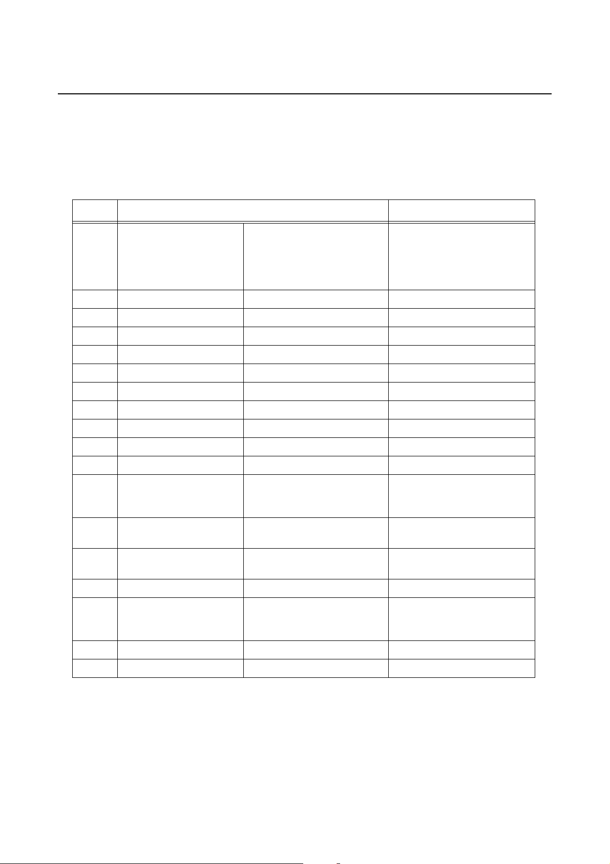
4.1 ERROR SIGNAL TROUBLESHOOTING
The ON LINE (POWER) and ERROR indicators light or flash in different colors and patterns listed below to
alert user that an error has occurred on the printer. [Indicator sequence (as shown from left to right): Off,
Red light, Green light]
ON LINE
Contents
(POWER)
LED
Hardware error
FLASH ROM
error
Setting
information
(FROM) error
Machine
error
Off Solid red 1 long
Program error
Incorrect
program
error
Off Solid red — 1) Download did not
Communication error
ERROR
LED
Buzzer Causes Corrective Actions
1), 2) Board replacement.
1), 2) Board replacement.
1) Download again.
beep
sound
1) FLASH ROM read/ write
error.
2) Exceeded the FLASH
ROM write count limits.
1) FLASH ROM read/write
error.
2) Exceeded the FLASH
ROM write count limits.
1) Board defect. 1) Board replacement.
complete successfully.
Communication error by
kit
Buffer over 1) Received the amount of
Off [Red->Off] x
twice
->Red x twice>Off
(blinks with
changing inter-
val)
1 long
beep
sound
Error contents may vary
depending on the kit
installed.
data exceeding the limit
of receive buffer.
2) Wrong protocol.
Download error
Download
error
Off Red x 4 times -
>Off
(longest blink
interval)
1 long
beep
sound
1) Downloaded wrong data. 1) Download again.
1) Correct the software on
the host side.
2) Set the correct protocol.
Page 4-2 LD610 User’s Technical Reference
Page 51
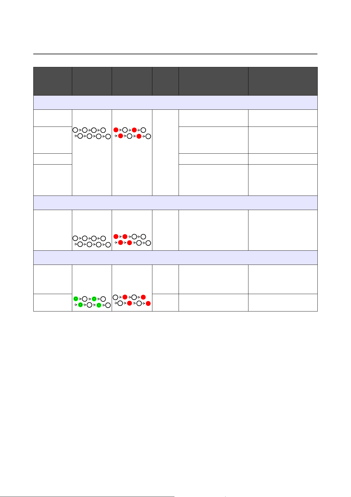
4.1 ERROR SIGNAL TROUBLESHOOTING (Cont’d)
Section 4: Troubleshooting
Contents
ON LINE
(POWER)
LED
ERROR
LED
Buzzer Causes Corrective Actions
Minor error
Cover open Off Blinking red 3 short
beeps
sound
Sensor error 1) Wrong sensor level.
Paper end 1) Out of paper. 1) Set the paper properly.
Ribbon end 1) Out of ribbon or ripped
1) Cover is not closed
properly.
2) Wrong sensor type.
3) Label meandering.
ribbon.
2) Ribbon is not set
properly.
1) Close the cover.
1) Level adjustment.
2) Sensor type adjustment.
1) & 2) Set the ribbon
properly.
Option
Cutter error Off long blink
interval
3 short
beeps
sound
1) Cutter is not connected.
2) Cut operation was not
performed successfully.
1) Connect the cutter unit.
2) Set and feed the paper
again.
Warning
Buffer near
full
Ribbon near
end
Blinking green
(Lights
alternately)
Blinking red
(Lights
alternately)
— 1) Free space for receive
buffer is low.
— 1) Remaining amount of rib-
bon is little.
1) Pause the data transmission on the host side and
wait to have enough
buffer space.
1) Ribbon replacement.
LD610 User’s Technical Reference Page 4-3
Page 52
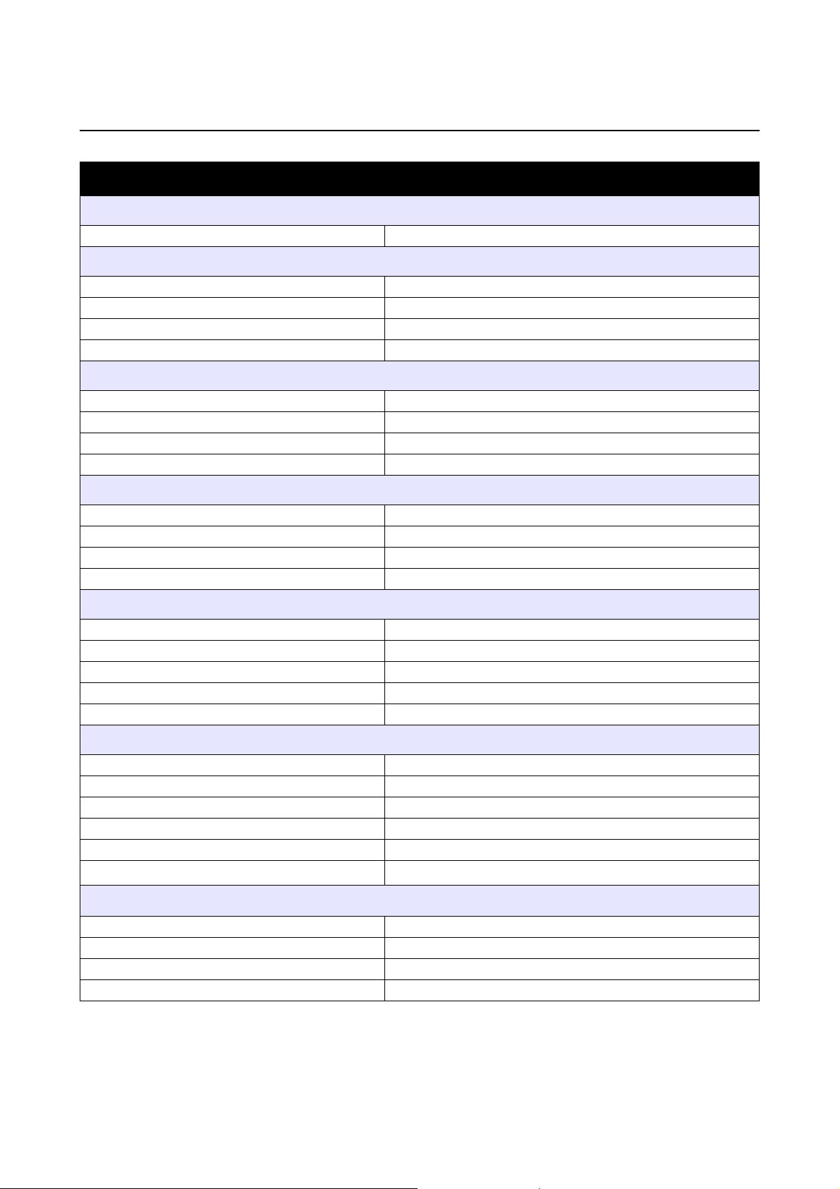
Section 4: Troubleshooting
4.2 TROUBLESHOOTING TABLE
TROUBLESHOOTING TABLE
NO POWER
Printer does not turn on. Power connector or AC adapter is not properly connected.
NO LABEL MOVEMENT
Media is not set properly. Set media and media guide correctly
Incorrect label sensor selected. Set the sensor correctly by printer setting to ol .
Dirty platen roller. Clean the platen roller.
Damaged platen gear. Replace platen rol ler and gear.
INCORRECT LABEL POSITIONING
Incorrect label sensor selection. Set the sensor correctly by printer setting tool.
Improper sensor adjustment. Adjust sensor sensitivity as required.
Data input error. Ensure correct data stream.
Incorrect offset settings. Adjust settings as required by command.
NO PRINT MOTION
The interface cable is not properly connected. Connect the interface cable.
Interface problems. Troubleshoot interface - refer to the next section.
Data input error. Ensure correct data stream.
Defective main circuit board. Have OKI authorized servicing personnel replace main board.
PRINTER CREATES A BLANK LABEL
Data input error. Ensure correct data stream.
Incorrect label sensor selection. Set the sensor correctly by printer setting tool.
Print head is disconnected. Power off the printer and ensure a proper connection.
Defective print head. Replace print head as required.
Defective main circuit board. Have OKI authorized servicing personnel replace main board.
IMAGE VOIDS
Dirty print head. Clean print head.
Defective print head. Replace print head.
Defective main circuit board. Have OKI authorized servicing personnel replace main board.
Damaged or worn platen roller. Replace platen roller.
Poor label quality. Use higher quality media. Use only OKI-certified media.
Ribbon stock and media are mismatched. *
RIBBON WRINKLING *
1
1
Consult with media supplier. Use only OKI-certified media.
Damaged or worn platen roller. Replace platen roller.
Foreign material on print head and/or platen roller. Clean as required.
Foreign material on labels. Use higher quality media. Use only OKI-certified media.
Defective print head. Replace print head as required.
*1 Ribbon stock conditions are only applicable to LD610 T printers.
Page 4-4 LD610 User’s Technical Reference
Page 53
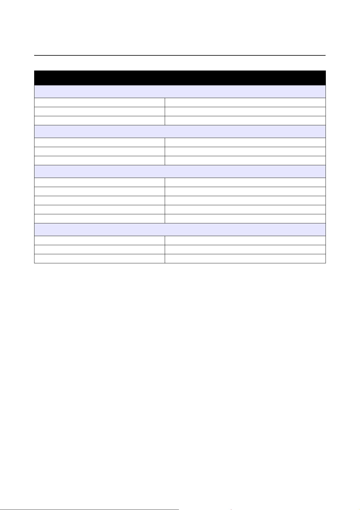
Section 4: Troubleshooting
4.2 TROUBLESHOOTING TABLE (Cont’d)
TROUBLESHOOTING TABLE
LIGHT PRINT IMAGES
Low print head darkness. Adjust darkness level setting.
Foreign material on print head. Clean print head and platen roller.
Excessive print speed. Reduce print speed setting.
UNEVEN PRINT DARKNESS
Damaged or worn platen roller. Replace platen roller.
Dirty print head. Clean print head.
Defective print head. Replace print head as required.
SMEARED PRINT IMAGES
Poor media quality Use higher quality media. Use only OKI-certified media.
Foreign material on print head and platen roller Clean print head and platen roller.
Foreign material on labels Use higher quality media. Use only OKI-certified media.
Excessive print head energy Adjust darkness level setting.
Excessive print speed Adjust print speed as required.
MEANDERING MEDIA
Incorrectly loaded media. Ensure correct loading.
Media is not set properly. Set media and media guide correctly.
Damaged or worn platen roller. Replace platen roller.
LD610 User’s Technical Reference Page 4-5
Page 54
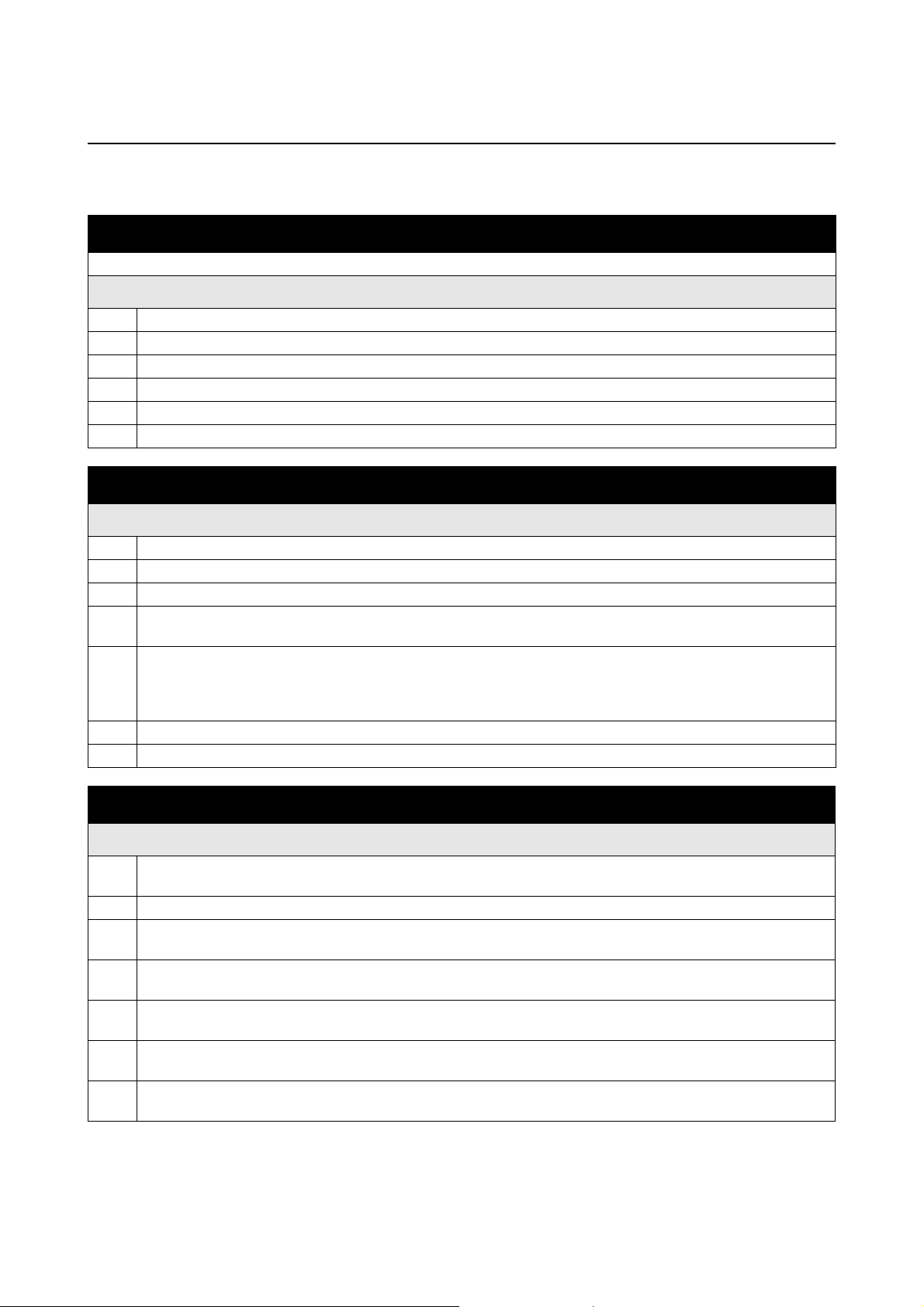
Section 4: Troubleshooting
4.3 INTERFACE TROUBLESHOOTING
This chapter provides a checklist for the vari ous interface types. Locate the checklist relative to the interface
used and perform each of the troubleshooting tasks until the problem has been isolated.
UNIVERSAL SERIAL BUS (USB) INTERFACE
If nothing prints during a test print, verify the device drivers have been successively installed by performing the following:
CHK TROUBLESHOOTING STEP
Click on Start, Settings, and then Control Panel.
Click on System within the new window.
Click on the Device Manager tab.
Ensure that the View Device By Type is checked.
Scroll to OKI-USB Device and ensure that errors do not exist. Reinstall as required.
Reboot the PC and the printer.
RS232 SERIAL INTERFACE
CHK TROUBLESHOOTING STEP
Ensure the correct interface module is correctly installed. Run self-test to verify.
Ensure the serial cable (Null Modem) meets specifications and is correctly connected at each end.
Ensure the serial cable is not defective.
Ensure the communication parameters for the baud rate, parity, data bits and stop bits are consistent with those
being sent from the host computer.
Ensure the printer is receiving information from the computer using the Receive Buffer Hex Dump mode. Refer to
that procedure within this manual for instructions. The command stream should be continuous and possess
0Dhex and/or 0Ahex (carriage return and line feed) characters throug hout. However, there should not be either
located between the start (<ESC>A) and the stop (<ESC>Z) commands.
Try another port to isolate the problem.
Replace the main circuit board if determined to be the problem.
LAN ETHERNET INTERFACE
CHK TROUBLESHOOTING STEP
Ensure the interface has been correctly configured. Wait two minutes and run self-test to verify. If a test label
does not print, there may be a hardware problem.
Ensure the cable and its ports are not defective.
Ensure that a faulty print server or other protocol related scenarios are not creating a queue setup issue.
Systematically perform checks and tests to isolate the cause.
If using TCP/IP, ensure that a valid IP address is specified and that all parameters are correct (subnet mask,
gateway, etc.). Attempt to PING the IP address assigned to the network interface.
If using a repeater or hub, ensure the SQE is turned off. Also ensure the repeater port i s not defective by trying
the print server on another port.
Install the IPX/SPX protocol on a workstation to determine if the network device can be discovered via the MAC
address. If able, configure the appropriate protocols and retest connectivity.
Use a crossover cable to isolate the printer from the netwo rk by connecting from the interface and workstation.
Verify that the parameters match on each. Test connectivity.
Page 4-6 LD610 User’s Technical Reference
Page 55

4.3 INTERFACE TROUBLESHOOTING (Cont’d)
PARALLEL INTERFACE
CHK TROUBLESHOOTING STEP
Ensure the interface module is correctly installed. Run self-test to verify.
Ensure the printer cable is connected to the appropriate LPT port on th e host computer. If using a Windows
printer driver, ensure the correct port is selected.
Ensure a IEEE1284 printer cable is being used.
Ensure the host’s peripheral settings are set to ECP for faster throughput. Refer to the computer manufacturer’s
documentation for details.
Ensure the printer is receiving information from the computer using the Recei ve Buffer Hex Dump mode. Refer
to that procedure within this manual for instructions . The command stream should be continuous and possess
0Dhex and/or 0Ahex (carriage return and line feed) characters throughout. However, there should not be either
located between the start (<ESC>A) and the stop (<ESC>Z) commands.
Try another port to isolate the problem.
Replace the main circuit board if determined to be the problem.
Section 4: Troubleshooting
CENTRONICS INTERFACE
CHK TROUBLESHOOTING STEP
Ensure the interface module is correctly installed. Run self-test to verify.
Ensure the printer cable is connected to the appropriate LPT port on the host computer. If using a Windows
printer driver, ensure the correct port is selected.
Ensure the host’s peripheral settings are set for Centronics output for faster throughput. Refer to the computer
manufacturer’s documentation for details.
Ensure the printer is receiving information from the computer using the Receive Buffer Hex Dump mode. Refer
to that procedure within this manual for instructions. The command stream should be co ntinuous and possess
0D Hex and/or 0A Hex (carriage return and line feed) charac ters throughout. However, there should not be
either located between the start (<ESC>A) and the stop (<ESC>Z) commands.
Replace the main circuit board with another to isolate the problem.
4.4 TEST PRINT TROUBLESHOOTING
This chapter provides instruction on special printing to identify and resolve specific print problems.
4.4.1 Hex Dump
Allows the operator to determine if there were problems in the downloading of data. The contents of the print
buffer can be examined using the Hex Dump Mode. In the left column, each line of data received is
numbered. The center column provides the data in hexadecimal format. And in the right column, the same
data are provided in the ASC ll format. Refer to Section 3.9 HEX Dump Mode for more details to perform this
activity.
4.4.2 Test label printing
Allows the operator to identify spec ific pr oble ms re gard ing me chan ical pe rfor man ce an d set up. T he te st lab el
is designed to assist in the identification of print problems. Refer to Section 3.3 User Test Print Mode for
more details to perform this activity.
LD610 User’s Technical Reference Page 4-7
Page 56

Section 4: Troubleshooting
This page is intentionally left blank
Page 4-8 LD610 User’s Technical Reference
Page 57
Section 5: Cleaning and Maintenance
CLEANING AND MAINTENANCE
This section provides information on user maintenance for the LD610 Series printer.
The following information is covered here:
• 5.1 Cleaning The Print Head, Platen and Rollers
• 5.2 How To Clean The Printer (Cleaning Kit)
• 5.3 How To Clean The Printer (Cleaning Sheet)
• 5.4 Easy Replacement of Parts
• 5.5 Adjusting Print Quality
Caution
• When cleaning the print head, bear in mind that the print head and its surroundings may be hot. W ait
until the printer cools down before proceeding to clean the printer.
• Be sure to turn off the power before cleaning.
• The suggested cleaning schedules here are just guidelines. If necessary, clean as appropriate,
depending on the degree of contamination.
• Use a cleaning pen, cotton swab or cotton clot h, from an approved cleaning kit, to clean the printer
units.
• Use only soft, lint-free materials for cleaning. Avoid using hard objects for the cleaning process, as
they will damage the components.
LD610 User’s Technical Reference Page 5-1
Page 58

Section 5: Cleaning and Maintenance
5.1 CLEANING THE PRINT HEAD, PLATEN AND ROLLERS
The print head not only generates printouts of barcodes, but also graphics and text. To produce optimal
printing, it must be kept clean in spite of the dirt and adhesive that constantly accumulates on its print surface.
Furthermore, dirt can accumulated along the la bel pa th, affecting p arts like se nsors an d guides , and reducin g
their performance.
Therefore, it is important to clean these important components periodically. The printer cleaning kit and
cleaning sheets can be purchased from your authorized OKI representative.
When to clean with a cleaning kit
♦ For the print head, platen roller, paper sensor, and label guide: clean after using up every other roll of
media.
♦ For other parts: clean after finishing every six rolls of media.
When to clean with the cleaning sheet
♦ For print head: clean after using every six rolls of media, or when you find any b urned gla ze on th e surf ace
of the print head.
5.2 HOW TO CLEAN THE PRINTER (CLEANING KIT)
If you are using a carbon ribbon, be sure to remove it before cleaning. Follow the instructions supplied with
the cleaning kit. Use the items to clean the following parts.
1. Before starting, get ready an approved cleaning kit from
your OKI representative. Make sure the printer is
powered off, and remove the power cable.
2. Lift the Top Cover.
3. Remove the media and the ribbon.
Cleaning the Print Head
4. Apply Thermal Print Head Cleaner to a cotton swab.
5. Locate the Print Head Assembly which is mounted
under the Top cover. The Print Head faces downward
along the front edge of the assembly.
Press the end of the dampened swab along the entire
width of the Print Head.
6. Check for any black coloring or adhesive on the swab
after cleaning. Discard the dirty swabs.
7. Repeat, if necessary, until the swab is clean after it is
pressed over the print head.
Cleaning the platen roller, senso r an d la b el g ui de
8. The platen roller is the black rubber roller near the front
panel. Wet some cotton swabs or cotton cloth with
cleaning solution. While rotating the platen roller with
your fingers (see arrow), clean the entir e len gt h of the
roller using one or more cotton swabs. Wipe any dirt or
accumulated adhesive off the platen roller.
Page 5-2 LD610 User’s Technical Reference
Page 59

Section 5: Cleaning and Maintenance
5.2 HOW TO CLEAN THE PRINTER (CLEANING KIT) (cont’d)
Locate the I-Mark sensor and Gap sensor on the left
9.
Media guide.
10.Dab a cotton cloth with the same cleaning solution. Clean
any foreign matter from the exposed surface of the media
guides and sensor. Insert the cotton cloth in the slot of the
media guide and briskly clean it with a back and forth
motion.
I-Mark and Gap
sensor is
underneath the
media guide
Media guide
11.Repeat the whole cleaning process when it is necessary.
The platen roller should be cleaned whenever foreign
matter, such as dust or adhesive, is present.
5.3 HOW TO CLEAN THE PRINTER (CLEANING SHEET)
If certain stains on the print head cannot be removed easily with cotto n swabs dabbed in cleaning solution, the
cleaning sheet is used for clearing such stubborn debris on the print head.
1. Make sure the printer is powered off and remove the power cable.
2. Lift the Top Cover.
3. Remove the media and the ribbon.
4. Place the head cleaning sheet between the print head
and the platen roller. The coarse side of the cleaning
sheet should face the surface of the print head
elements.
5. Close the top cover with approximately 25mm (1 inch)
of the cleaning sheet extended out of the printer.
6. Using both hands, slowly pull the exposed cleaning
sheet outwards. This will remove any dirt stuck to the
print head.
7. When the cleaning sheet has been removed, perform
steps 2 to 6 to repeat the cleaning p rocedur e o ne or two
more times.
8. When no more additional dirt appears on the cleaning
sheet after it has been pulled out, you can stop cleaning
with the sheet.
9. Use the cleaning pen from the cleaning kit or use a cotton swab moistened with head cleaner to gently
remove any remaining dirt from the print head.
LD610 User’s Technical Reference Page 5-3
Page 60

Section 5: Cleaning and Maintenance
5.4 EASY REPLACEMENT OF PARTS
It is easy to replace the print head and platen roller of the LD610 Series printer.
The one-touch, tool-less print head release mechanism enables the print head to be quickly and easily
replaced. The platen roller can be replaced without the need to use any tools.
5.4.1 Releasing/ Replacing the Print Head
The print head on the printer is a user-replaceable item. If it becomes damaged for any reason, it can b e
easily removed and replaced. Contact your local OKI representative for information on obtaining a new print
head.
Caution
• Sta tic electricity can result in component damage. Observe appropriate grouping procedures
when replacing any components.
• Wear protective gloves to avoid contaminating the sensitive print head surface.
For LD610 D Direct Thermal printer
1. Make sure the printer is turned off, and remove the power
cable.
1
2
2. Lift the Top Cover.
3. While pressing and hold down the top portion of the print
head assembly (see arrow ), slide the side tab ()
downward to unlock the print head assembly. Shift the print
head assembly to the right and pull the whole print head
assembly downward.
1 2
4. The cable connectors (circled) at the rear of the print
head is now exposed. Pull the print head downward, then
gently disconnect the defective print head from the cable
connectors.
5. Carefully connect the cable connectors to a replacement
print head. The white cable should be connected to the
left connector while black cable should be connected to
the right connector. The connectors are keyed so that they
can only be inserted in the correct orientation.
Caution:
While handling the print head, be careful not to scratch the
printing surface of the print head. Scratching the surface
will cause permanent and irreparable damage that is not
covered by the warranty!
6. Insert the left shaft of the new print head assembly into
the hole beside the triangular symbol on the left side of
printer. (see circled area).
3
Print head
assembly
Page 5-4 LD610 User’s Technical Reference
Page 61

5.4 EASY REPLACEMENT OF PARTS (cont’d)
Align the two circular recess of the print head bracket to
7.
the two springs attached to th e top cover frame. At the
same time, fix the fulcrum shaft of the p r int head b rac ket
to the hooks. While pressing the print head, slide the side
tab upwards to lock the print head assembly in place.
8. Close the Top Cover.
9. Restore power, reload media, reset the head counter and
perform a test print to ensure that the print head is
connected properly.
Section 5: Cleaning and Maintenance
Hooks
Fulcrum shaft
Circular
recess
LD610 User’s Technical Reference Page 5-5
Page 62

Section 5: Cleaning and Maintenance
5.4 EASY REPLACEMENT OF PARTS (cont’d)
5.4.2 Releasing/ Replacing the Platen roller
1.
Make sure the printer is powered off and remove th e p ower
cable.
2. Lift the Top Cover.
3. Locate the two platen bearings on each side of the platen
roller, and turn the handles in the direction as shown.
4. Lift up the defective platen roller assembly with the
handles and replace it with a new one.
5. Follow the above steps, in reverse sequence, to
reassemble the parts. Make sure that the platen bearing
snaps back in position.
Perform a label feed to ensure the platen roller is
assembled correctly.
Page 5-6 LD610 User’s Technical Reference
Page 63

Section 5: Cleaning and Maintenance
5.5 ADJUSTING PRINT QUALITY
Print quality can be optimized with regular cleaning and maintenance of the print head and components along
the label path. Additionally, you can fine-tune print quality by adjusting print darkness and print speed settings.
When adjusting the printer for optimum print quality, a barcode verifier system is highly recommended for
evaluating the printouts. The human eye is a poor judge of the relative widths of the bars in a symbol, a
characteristic that is extremely important for good barcode quality.
Print Darkness
This adjustment allows the user to control (within a specified range) the amount of power that is used to
activate the print head heating elements. It is important to find a proper print darkness level based on your
particular label. The printed images should not be too light nor should the edges of text or graphics be
smudged. Instead, the edges of each image should be crisp and well defined. The adjustment can be made
via standard SBPL commands or by the Utilities Tool application.
Print Speed
The other method of controlling print quality is by controlling the speed at which the label is printed. It is
especially critical when printing “ladder” barcodes (barcodes printed with the bars parallel to the print line).
When printing a “ladder” barcode, it is important to allow the head to cool sufficiently before stepping to the
next position. If it does not have sufficient time to cool, the bar will be “smeared” on the trailing edge. The
adjustment can be made via standard SBPL commands or by the Utilities Tool application.
LD610 User’s Technical Reference Page 5-7
Page 64

Section 5: Cleaning and Maintenance
This page is intentionally left blank
Page 5-8 LD610 User’s Technical Reference
Page 65

GENERAL SPECIFICATIONS
6.1 PRINTER BASIC SPECIFICATIONS
Section 6: General Specifications
MODEL NAME
LD610 D LD610 T
PHYSICAL CHARACTERISTICS
Width 179 mm (7.05”)
Depth 238 mm (9.37”)
Height 173 mm (6.81”)
Weight 1.7 kg (3.7 lbs.) 1.9 kg (4.19 lbs.)
POWER SUPPLY (AC ADAPTER)
Input Voltage 100-240 V AC, +/-10%, 50/60 Hz (Full range)
Output Voltage 19 V DC, +/-5%, 3.86A
At peak times: 50 Watts
Power Consumption
During standby: 2.5 Watts
ENVIRONMENTAL (EXCLUDING MEDIA)
Operating Temperature 4° to 38°C (39.2 to 100.4°F)
Storage Temperature -10° to 60°C (14 to 140°F)
Operating Humidity 30 to 80% RH, Non-condensing
Storage Humidity 15 to 85% RH, Non-condensing
PRINT
Method DT models: Direct Thermal only
50, 75 or 100 mm/second
Print Speed (selectable)
*Maximum print speed varies depending on the of media used.
Resolution 8 dots/mm (203 D ots Per Inch) 8 dots/mm (203 Dots Per Inch)
Maximum Print Width 104 mm (4.09”)
Maximum Print Length 300 mm (11.81”)
2, 3 or 4 Inches/second (Setting: 2, 3, 4)
LD610 User’s Technical Reference Page 6-1
TT models: Thermal Transfer and
Direct Thermal
Page 66

Section 6: General Specifications
MODEL NAME
LD610 D/ LD610 T
MEDIA (Be sure to use media manufactured or certified by OKI)
Type
Wind Direction Roll stock: Face In or Face out winding
Roll and Core Diameter
Fanfold Max. stack height 118 mm (4.65”) (external supply)
Label
Continuous
Cutter
Dispenser
Tear-off
Size
Linerless
Non-adhesive paper
Continuous
Cutter
Tear-off
*1 Media using small pitch must be torn by hand.
• The above size may be limited by use conditions, such as type of paper, usage
• When using the dispenser mode, restrictions apply to the maximum paper length
Thickness 0.06 to 0.19 mm (0.0024” to 0.0074”)
Direct Thermal / Thermal Transfer depending on print model (D or T)
Roll stock or Fan-fold
Maximum outer diameter: 128 mm (5.04”) with Inner core diameter: 40 mm (1.5”)
* Inner core diameter: 19.05 mm (0.75”) with maximum outer diameter: 110 mm
(4.33”) can be accepted, but there is no performance guarantee.
Pitch
: 7 to 300 mm (0.27” to 11.8”)
Pitch including liner
Width
: 22 to 107 mm (0.86” to 4.21”)
Width including liner
Pitch
: 22 to 300 mm (0.87” to 11.8”)
Pitch including liner
Width
: 22 to 107 mm (0.87” to 4.21”)
Width including liner
Pitch
: 22 to 100 mm (0.87” to 3.93”)
Pitch including liner
Width
: 22 to 107 mm (0.87” to 4.21”)
Width including liner
Pitch
: 22 to 300 mm (0.87” to 11.8”) *
Pitch including liner
Width
: 22 to 107 mm (0.87” to 4.21”)
Width including liner
Pitch
: 25 to 100 mm (0.98” to 3.93”) *
With
: 25 to 110 mm (0.98” to 4.33”)
Pitch
: 10 to 303 mm (0.39” to 11.93”) *
Width
: 25 to 110 mm (0.98” to 4.33”)
Pitch
: 25 to 303 mm (0.98” to 11.93”)
Width
: 25 to 110 mm (0.98” to 4.33”)
Pitch
: 25 to 303 mm (0.98” to 11.93”) *
Width
: 25 to 110 mm (0.98” to 4.33”)
environment, and application.
according to paper installation conditions.
: 10 to 303 mm (0.39” to 11.93”)
: 25 to 110 mm (0.98” to 4.33”)
: 25 to 303 mm (0.98” to 11.93”)
: 25 to 110 mm (0.98” to 4.33”)
: 25 to 103 mm (0.98” to 4.05”)
: 25 to 110 mm (0.98” to 4.33”)
: 25 to 303 mm (0.98” to 11.93”)
: 25 to 110 mm (0.98” to 4.33”)
1
1
1
1
Page 6-2 LD610 User’s Technical Reference
Page 67

Section 6: General Specifications
MODEL NAME
LD610 D LD610 T
RIBBON (Be sure to use ribbon manufactured or certified by OKI)
Wind Direction
Winding Method Paper core
Roll Diameter Maximum outer diameter: 38 mm (1.4”)
Core Diameter Inner core diameter: 12.7 mm (0.5”)
Length
Width
—
Max. 100m (328 ft.), Do not exceed the
maximum outer diameter.
Use only 110mm +/- 0.5mm
PROCESSING
CPU 32 Bit RISC-CPU 133MHz
Flash ROM 4 Megabytes
SDRAM 8 Megabytes
PRINTER LANGUAGE
Standard OKI Barcode Printer Language (SBPL)
Face Out
(4.33” +/- 0.01”)
INTERFACES
Select one of the following. (The factory will provide the unit with the selected
interface.)
1) USB 2.0 (Type B) with RS-232C (D-SUB 9-pin type) or
Standard Configurations
2) USB 2.0 (Type B) with LAN (10BASE-T/100BASE-TX Automatic Switching) or
3) USB 2.0 (Type B) with IEEE1284
*The RS-232C connector can be used to connect the printer to a computer, an
optional keypad, Smart keyboard or Barcode scanner.
SENSING
Gap (Transmissive) Sensitivity Adjustable
I-Mark (Reflective) Sensitivity Adjustable
Cover Open Fixed
Ribbon End Not available
Dispenser Fixed (Only available if installed)
Linerless label sensor Fixed (Only available if installed)
LABEL ISSUING MODES
Standard: Continuous mode, Tear -off mode, Sensor off mode
Optional mode: Dispenser mode, Cutter mode, Linerless (Nonesepa) mode
Fixed (Only available for Thermal
Transfer model)
LD610 User’s Technical Reference Page 6-3
Page 68

Section 6: General Specifications
MODEL NAME
SELF-DIAGNOSIS
Cover Open Detection
Cutter error (Only available if installed)
CHARACTER FONT CAPABILITIES
BITMAP FONTS
U 5 dots W x 9 dots H (Alphanumeric characters and symbols)
S 8 dots W x 15 dots H (Alphanumeric characters and symbols)
M 13 dots W x 20 dots H (Alphanumeric characters and symbols)
WB 18 dots W x 30 dots H (Alphanumeric characters and symbols)
WL 28 dots W x 52 dots H (Alphanumeric characters and symbols)
XU 5 dots W x 9 dots H (Alphanumeric characters and symbols)
XS 17 dots W x 17 dots H (Alphanumeric characters and symbols)
XM 24 dots W x 24 dots H (Alphanumeric characters and symbols)
XB 48 dots W x 48 dots H (Alphanumeric characters and symbols)
XL 48 dots W x 48 dots H (Alphanumeric characters and symbols)
OA Font (OCR-A)
OB Font (OCR-B)
(Alphanumeric characters and symbols)
(Alphanumeric characters and symbols)
LD610 D LD610 T
Cover Open Detection
Paper End Detection
Test Print
Ribbon end Detection
Cutter error (Only available if installed)
15 dots x 22 dots
(Alphanumeric characters and symbols)
20 dots x 24 dots
(Alphanumeric characters and symbols)
Paper Detection
Test Print
15 dots x 22 dots
20 dots x 24 dots
KANJI FONTS
OUTLINE FONTS
CHARACTER CONTROL
Magnification Expansion up to 12 x in either the vertical or horizontal
Rotation 0°, 90°, 180° and 270°
Supported by downloading one of the following kanji fonts.
1) Simplified Chinese (2.6MB)
Gothic type GB2312 (24 x 24 dot)
2) Korean (1.6MB)
Gothic type KSX1001 (16 x 16 dot)
Mincho type KSX1001 (24 x 24 dot)
Alphanumeric characters and symbols
Page 6-4 LD610 User’s Technical Reference
Page 69

Section 6: General Specifications
MODEL NAME
LD610 D LD610 T
BARCODE CAPABILITIES
UPC-A/UPC-E, EAN8/13, CODE39, CODE93, CODE128,
Linear Bar Codes
Two Dimen s ional codes PDF417 (Ver.2.4), MAXI code (Ver.3.0), QR code, GS1 DataMatrix (ECC200)
Composite Symbols
Ratios 1:2, 1:3, 2:5, User definable bar widths
Magnification 1 x to 12 x
Rotation Parallel 1 (0°), Parallel 2 (180°), Serial 1 (90°) and Serial 2 (270°)
GS1-128 (UCC/EAN128), CODABAR(NW-7), ITF, Industrial 2 of 5, Matrix 2 of 5,
BOOKLAND, MSI, POSTNET, GS1 DataBar (RSS)
* GS1 DataBar is new version of RSS-14.
EAN-13 Composite (CC-A/CC-B)
EAN-8 Composite (CC-A/CC-B)
UPC-A Composite (CC-A/CC-B)
UPC-E Composite (CC-A/CC-B)
GS1-128 Composite (CC-A/CC-B/CC-C)
GS1 DataBar Composite (CC-A/CC-B)
GS1 DataBar Truncated Composite (CC-A/CC-B)
GS1 DataBar Stacked Composite (CC-A/CC-B)
GS1 DataBar Stacked Omni-Directional Composite (CC-A/CC-B)
GS1 DataBar Limited Composite (CC-A/CC-B)
GS1 DataBar Expanded Composite (CC-A/CC-B)
GS1 DataBar Expanded Stacked Composite (CC-A/CC-B)
* GS1 DataBar is new version of RSS-14.
STAN DARD FUNCTIONS
1) Status return function
2) Graphic function
3) Sequential number function
4) Form overlay function
5) Custom character registration function
6) Black/white inversion function
7) Ruled line function
8) Format registration function
9) Zero slash switching function
LD610 User’s Technical Reference Page 6-5
Page 70

Section 6: General Specifications
MODEL NAME
HARDWARE AND RELATED
Operation keys POWER and FEED/LINE buttons
Indicators
Buzzer
Surface Treatment
• On/ off switchable buzzer (specified by command)
• No volume control function available
OPTIONS
LD610 D LD610 T
ON LINE (POWER): Green LED
ERROR: Red LED
Built-in buzzer
Antibacterial finishing for external cover and operative parts.
Tested according to JIS Z 2801 standard
1) Cutter Unit
2) Dispenser Unit
3) RTC kit (Calendar IC)
4) Linerless (Nonesepa) Unit
5) Keypad*
6) Compatible smart keyboard*
7) Compatible 1D barcode scanner*
*Applicable to USB and RS232C interface model only. Connect to RS232C
terminal.
REGULATORY COMPLIANCE
UL60950-1(2001) (USA)
Safety regulation
EMC regulation
Packing Drop Standard ISTA-2A
Environmental (RoHS)
Polybrominated Diphenyl Ether (PBDE): below 0.1%
CSA22.2 No.60950-1-30 (Canada)
EN60950-1, CE (Europe)
CCC (GB4943-2001) (China)
FCC15B Class B (USA/Canada)
CE (EN55022, EN55024) (Europe)
GB9254-1998, GB17625.1(2003) (China)
KN22, KN24 (Korea)
Chromium: below 0.1%
Lead: below 0.1%
Mercury: below 0.1%
Cadmium: below 0.01%
Polybrominated Biphenyl (PBB): below 0.1%
Page 6-6 LD610 User’s Technical Reference
Page 71

6.2 OPTIONAL ACCESSORIES SPECIFICATIONS
CUTTER SPECIFICATIONS
Media Type Non-adhesive paper and Label
Pitch
: 22 to 300 mm (0.87” to 11.8”)
Pitch including liner
Media Size
Width
Width including liner
Thickness 0.06 to 0.19 mm (0.0024” to 0.0074”)
Self-diagnosis function Cutter error detection
Durability More than 300,000 cuts
DISPENSER SPECIFICATIONS
* Some restrictions may apply to some label types depending on the substrate,
Media Type
Media Size
Thickness 0.06 to 0.19 mm (0.0024” to 0.0074”)
Sensor Type Dispenser sensor (Reflective type)
adhesive, paper size, and environment. Refer to OKI representative on the labels
to be used.
* Perforated liner and split liner cannot be used.
* Peel end labels
Pitch
Pitch including liner
Width
Width including liner
: 25 to 303 mm (0.98” to 11.93”)
: 22 to 107 mm (0.87” to 4.21”)
: 25 to 110 mm (0.98” to 4.33”)
Label only
: 22 to 100 mm (0.86” to 3.93”)
: 25 to 103 mm (0.98” to 4.05”)
: 22 to 107 mm (0.86” to 4.21”)
: 25 to 110 mm (0.98” to 4.33”)
Section 6: General Specifications
LINERLESS (NONESEPA) KIT SPECIFICATIONS
Media Type Micro-perforated Linerless (Nonesepa) Label
Pitch
: 25 to 100 mm (0.98” to 3.93”)
Media Size
With
: 25 to 110 mm (0.98” to 4.33”)
Thickness 0.06 to 0.19 mm (0.0024” to 0.0074”)
Media Winding direction Face-out
Roll and core Diameter Maximum outer diameter: 128 mm (5.04”) with Inner core diameter: 40 mm (1.5”)
Sensor Type Label sensor (Reflective type)
Label issuing mode Continuous mode, Tear-off mode
LD610 User’s Technical Reference Page 6-7
Page 72

Section 6: General Specifications
This page is intentionally left blank
Page 6-8 LD610 User’s Technical Reference
Page 73
Section 7: Interface Specifications
INTERFACE SPECIFICATIONS
This section presents the interface types and their specifications for the LD610 Series printers. These
specifications include detailed information to assist in the selection of the most appropriate method for the
printer to interface with the host.
The following information is presented in this section:
• 7.1 Interface types
• 7.2 RS232C Serial Interface
• 7.3 IEEE 1284 Parallel Interface
• 7.4 Universal Serial Bus (USB) Interface
• 7.5 Local Area Network (LAN) Ethernet
7.1 INTERFACE TYPES
The LD610 Series has three types of Main PCBs. Each type of PCB is equipped with two different interface
types for performing data communication with the host. These are described as follows.
1) Type 1: USB and LAN on-board
2) Type 2: USB and RS232C on-board
2) Type 3: USB and IEEE1284 on-board
Model
USB LAN RS232C
LD610 series (Type 1) Yes Yes - LD610 series (Type 2) Yes - Y es LD610 series (Type 3) Yes - - Yes
Interface Types
IEEE1284
Caution
Never connect or disconnect interface cables (or use a switch box) with power applied to either the host
or printer. This may caused damage to the interface circuitry in the printer/ host and is not covered by
warranty.
LD610 User’s Technical Reference Page 7-1
Page 74

Section 7: Interface Specifications
7.2 RS232C SERIAL INTERFACE
7.2.1 Basic Specifications of RS-232C Serial Interface
This interface complies with the RS-232C standard.
Interface connector
DB-9S or equivalent (Male)
Cable length: 5m or less
Communication
settings
Use Printer configuration tool or <I2> command to setup.
<I2>abcde
Parameter Item Value Description
2 38400bps
a Baud rate
b Data bit length
c Parity bits
d Stop bits
1 19200bps [Default]
0 9600bps
17 bits
0 8 bits [Default]
2 EVEN
1ODD
0 NONE [Default]
12 bits
0 1 bit [Default]
4STATUS 3
3 Protocol for driver (STATUS 4)
[Default]
e Protocol
2 XON/XOFF
1 READY/BUSY (Multi item buffer)
0 READY/BUSY (Single item
buffer)
Page 7-2 LD610 User’s Technical Reference
Page 75

Section 7: Interface Specifications
7.2 RS232C SERIAL INTERFACE (cont’d)
Function descriptions
Function Description
Baud rate setting Select the data rate (bps) for the RS232 port.
Data bit length Sets the printer to receive either 7 or 8 bits of data for each byte transmitted.
Parity setting Selects the type of parity used for error detection.
Stop bit setting Selects the number of stop bits to end each byte transmission.
Protocol setting Selects the flow control and status reporting protocols
Synchro system Asynchronous method
Maximum receive
buffer capacity
1MB
0MB
Buffer near full
occurred
Buffer near full
released
Code ASCII (7 bits), Graphic (8 bits)
Transmission form
Star t
b1 b2 b3 b4 b5 b6 b7 b8
[Note] If using 7 bits, b8 will be omitted.
Signal level High level
Low level
: +5 to +12V
: -5 to -12V
Interface type Use Printer configuration tool or <DI> command.
<DI>a
Parameter Item Value Description
0USB
a
Interface
selection
1 RS-232C
2Keypad
1MB
Remaining 0.25MB
Remaining 0.5MB
Stop
3 Scanner/ Smart keyboard
LD610 User’s Technical Reference Page 7-3
Page 76

Section 7: Interface Specifications
7.2 RS232C HIGH SPEED SERIAL INTERFACE (cont’d)
7.2.2 Ready/Busy
This protocol controls the reception of print data only by the control of hardware signal. Use the command
<I2> to toggle between single item buffer and multi item buffer.
When the print data (STX ESC+”A”~ ESC+”Z” ETX) is sent from the host in the conditions below, received
data may be incorrect.
1) When the printer is Offline
2) When an error has occurred in the printer
Pin Assignments
1)Host with DB-25P te rminal
Printer Host
CD 1 1 FG
RD 2 2 SD
SD 3 3 RD
ER 4 6 DR
SG 5 7 SG
DR 6 20 ER
RS 7 5 CS
CS 8 4 RS
RI 9
Interface Signals
Pin no. Signal Ty pe Direction Description
2 RD Input Data transferred from the host to the printer
3 SD Output Data transferred from the pr inter to the host
4 ER Output Data terminal READY
5 SG - Signal ground
2)Host with DB-9P termin al
Printer Host
CD 1 1 CD
RD 2 3 SD
SD 3 2 RD
ER 4 6 DR
SG 5 5 SG
DR 6 4 ER
RS 7 8 CS
CS 8 7 RS
RI 9 9 RI
6 DR Input Data set READY
7 RS Output Send request
8 CS Input READY to send
Notes:
Follow the procedures below when executing READY/BUSY control.
1) When the host sends the data for printing labels, make sure that the printer is on.
2) Turning the printer on after the printer receives a request from the host to print labels may cause the
printer not to print the first print data (approximately 120 bytes).
To avoid this problem, it is necessary to attach approximate 120 bytes of dummy data by application
software that enables the host to send the data for printing labels.
For example: When sending [STX+<A>+<V>20+<H>20+<P>2+<L>0202+<X20>,
1234+<Q>2+<Z>+ETX], transfer the appropriate 120 bytes of dummy data shown below.
[00H+00H+ ~ +00H+00H+00H+00H] + [STX ~ ETX]
Page 7-4
LD610 User’s Technical Reference
Page 77

Section 7: Interface Specifications
7.2 RS232C HIGH SPEED SERIAL INTERFACE (cont’d)
7.2.3 X-ON/X-OFF
This transmission protocol informs the host if the printer is ready to receive data, by sending the “XON” (Hex
11H) or “XOFF” (Hex 13H) code.
When the print data (STX ESC+”A”~ ESC+”Z” ETX) is sent from the host in the conditions below, received
data may be incorrect.
1) When the printer is Offline
2) When an error has occurred in the printer
Pin Assignments
1) Host with DB-25P terminal
Printer Host
RD 2 2 SD
SD 3 3 RD
SG 5 7 SG
2) Host with DB-9P terminal
Printer Host
RD 2 3 SD
SD 3 2 RD
SG 5 5 SG
Note:
Depending on the host used, it may need to loop CS and RS (maintaining at “High” level) on the host side.
Therefore, make sure to re-check the host before use.
Input/Output Signals
Pin no. Signal Ty pe Direction Description
2 RD Input Data transferred from the host to the printer
3 SD Output Data transferred from the pr inter to the host
5 SG - Signal ground
7.2.4 Return Status (STATUS 3 and Protocol for Driver (STATUS 4))
The purpose of these protocols is to control printer status on the host side. With the request command from
the host, the status is returned from the printer.
After receiving the request command, the status is returned immediately.
In these communication protocols, receive mode is set to multi item buffer.
When the print data (STX ESC+”A”~ ESC+”Z” ETX) is sent from the host in the conditions below, received
data may be incorrect.
1) When the printer is Offline
2) When an error has occurred in the printer
LD610 User’s Technical Reference Page 7-5
Page 78

Section 7: Interface Specifications
7.3 IEEE 1284 PARALLEL INTERFACE
7.3.1 Basic Specifications of IEEE1284 parallel interface
This interface complies with the Centronics/ IEEE1284 standard.
ECP mode is recommended for LPT1 port.
LPT1 port details can be set through a computer’s BIOS settings.
Interface connector
Printer side: Amphenol (DDK) 57 to 40360 or equivalent
Cable side: Amphenol (DDK) 57 to 30360 or equivalent
Cable length: 1.5m or less
Signal level High level
Low level
Communication
Use the <I1> command for the following settings.
condition setting
Receive mode Single item buffer
ACK width 010 to 200 (1=50ns)
Item Color
: +2.4 to +5.0V
: +0.0 to +0.4V
Multi item buffer
Communication protocol cannot be fixed at compatible mode because of
IEEE1284 negotiation.
Interface type Use Printer configuration tool or <DI> command.
<DI>a
Parameter Item Value Decription
0USB
Maximum receive
buffer capacity
a Interface
1MB
0MB
Buffer near full
occurred
Buffer near full
released
1 IEEE1284
1MB
Remaining 0.25MB
Remaining 0.5MB
DeviceID LD610
“MFG:OKI;CMD:PCL,MPL;MDL:LD610;”
Page 7-6
LD610 User’s Technical Reference
Page 79

Section 7: Interface Specifications
7.3 IEEE 1284 PARALLEL INTERFACE (cont’d)
7.3.2 Pin Assignments
Pin assignment of each signal for the Centronics standard (Compatible Mode) is as follows.
Note that the connection of the IEEE1284 standard complies with the IEEE1284-B standard.
PIN No. Signal I/O PIN No. Signal I/O
1STROBE
2 DATA 1 Input 20 DATA 1-RETURN
3 DATA 2 Input 21 DATA 2-RETURN
4 DATA 3 Input 22 DATA 3-RETURN
5 DATA 4 Input 23 DATA 4-RETURN
6 DATA 5 Input 24 DATA 5-RETURN
7 DATA 6 Input 25 DATA 6-RETURN
8 DATA 7 Input 26 DATA 7-RETURN
9 DATA 8 Input 27 DATA 8-RETURN
10 ACK
11 BUSY Output 29 BUSY -RETURN
12 PE Output 30 PE -RETURN
13 SELECT Output 31 INIT
14 AUTOFD Input 32 FAULT Output
15 33
Input 19 STROBE-RETURN
Output 28 ACK -RETURN
Input
16 LOGIC GND 34
17 CHASSIS GND 35
18 PERIPHERAL LOGIC
HIGH
LD610 User’s Technical Reference Page 7-7
Output 36 SELECTIN
Input
Page 80
Section 7: Interface Specifications
7.3 IEEE 1284 PARALLEL INTERFACE (cont’d)
7.3.3 Input/Output Signals
The details of each signal line for the Centronics standard (Compatible Mode) are as follows.
Note that each signal line complies with the IEEE1284 standard.
Signal I/O Description
STROBE Input Synchronization signal that requires low active pulse to read
D ATA1 ~ DATA8
DATA 1 ~ DATA 8 Input Data entry of 8bits parallel: DATA1 --LSB (lowest bit)
DATA8 --MSB (highest bit)
ACK
BUSY Output High active signal indicating that the printer is not ready to
PE Output High active signal indicating paper shortage
SELECT Output High active signal indicating that the printer is ready to receive
AUTOFD
CHASSIS GND Connecting to framework ground
PERIPHERAL LOGIC
HIGH
SIGNAL GND Connecting to each signal ground
INIT
FAULT
SELECTIN
Output Low active pulse signal indicating the completion o f receive data
import
receive data
data
Input Signal for the IEEE1284 standard
Output +5V voltage on the printer side
Input Low active pulse signal requesting to reset the printer
Output Low active pulse signal indicating an error in the printer
Input Signal for the IEEE1284 standard
Page 7-8
LD610 User’s Technical Reference
Page 81

Section 7: Interface Specifications
7.4 UNIVERSAL SERIAL BUS (USB) INTERFACE
This printer supports the USB 2.0-compliant interface and the transfer rate at 12.5 Mbits/second.
7.4.1 Basic Specifications of USB interface
The USB interface is available with all three types of boards.
Interface connector
Series B plug
Cable length: 5m or less (Twisted Pair Shielded)
Version USB 2.0
Maximum receive
buffer capacity
1MB
0MB
Buffer near full
occurred
Buffer near full
released
Interface type Use Printer configuration tool or <DI> command.
<DI>a
Parameter Item Value Description
0USB
1 RS-232C/LAN/IEEE1284
a Interface
2Keypad
3 Scanner/ Smart keyboard
7.4.2 Pin Assignments
1MB
Remaining 0.25MB
Remaining 0.5MB
Pin No. Description
1 VBus
2-Data(D-)
3+Data(D+)
4GND
LD610 User’s Technical Reference Page 7-9
Page 82

Section 7: Interface Specifications
7.4 UNIVERSAL SERIAL BUS (USB) INTERFACE (cont’d)
7.4.3 Host Computer Settings
Installation of USB Standard Print Support
It is necessary to install the USB driver in addition to the printer driver to perform print operation via the USB
port.
As for the USB driver installation procedure, refer to [How to Install the USB Standard Print Support] in the
printer driver installation specifications.
Notes
• OS environment corresponding to the USB interface is [Windows20 00/XP/Server2003/V ista], however, the
connection may not be established depending on the manufacturers or models. For mor e details, refer to
your host computer documentation.
• USB cable length under 1m is recommended.
• Device name of USB port should be "Serial number".
For example: CRGY0032
Page 7-10
LD610 User’s Technical Reference
Page 83

Section 7: Interface Specifications
7.5 LOCAL AREA NETWORK (LAN) ETHERNET
7.5.1 Basic Specifications of LAN
A Local Area Network (LAN) interface requires a driver shipped with each printer that has the interface
installed. The driver must be loaded on the h ost computer an d configured to run one of the supp orted network
protocols using a 10/100BaseT LAN connection.
Interface connector
Cable type: For 10BASE-T and 100BASE-TX
Cable length: 100m or less
Link/Status LED Status LED lights up when establishing the LINK with Ethernet equipment. The
LINK is established by Auto Negotiation.
LED Color Conditions
LINK Green Lights up when establishing the LINK
SPEED Orange Lights off when recognizing the destination
10BASE-T
Lights up when recognizing the destination
100BASE-TX
COLLISION Red Lights up when collision occurs
Maintenance function [Printing LAN configuration information]
LAN configuration information will be printed on the third sheet of user test print
and factory test print.
[Initializing LAN configuration information]
LAN configuration information will be initialized through [All Clear] of Factory
Clear Mode. For more details, refer to the authorized OKI servicing personnel.
Interface type Use Printer configuration tool or <DI> command.
<DI>a
Parameter Item Value Decription
0USB
a Interface
1LAN
LD610 User’s Technical Reference Page 7-11
Page 84
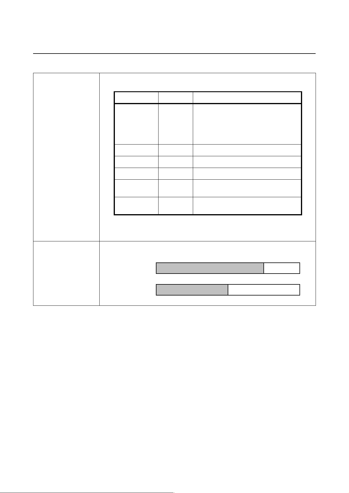
Section 7: Interface Specifications
7.5 LOCAL AREA NETWORK (LAN) ETHERNET (cont’d)
Communication
configuration
Maximum receive
buffer capacity
The following settings can be configured via the Printer configuration tool or commands.
Item Command Setting range
LAN mode
IP address
Subnet mask
Gateway address
IP address setup
RARP
1
2-port connection by Port1024 and Port1025 or 1 port conne ction by
*
<I3> Prot oco l for dr ive r (STATUS4 ) cyclic
response mode *
Protocol for driver (STATUS4) ENQ
response mode *
STATUS3 *
<W1> 0.0.0.0 ~ 255.255.255.255
<W2> 0.0.0.0 ~ 255.255.255.255
<W3> 0.0.0.0 ~ 255.255.255.255
<WI> Manual
DHCP
<WM> RARP disabled
RARP enabled
1
1
2
Port9100.
2
1 port connection by Port1024 or Port9100.
*
1MB
0MB
Buffer near full
occurred
Remaining 0.25MB
Buffer near full
released
Remaining 0.5MB
1MB
7.5.2 Software Specifications
Protocol TCP/IP
Network layer ARP, RARP, IP, ICMP
Session layer TCP, UDP
Application layer LPR, FTP, TELNET, BOOTP, DHCP, HTTP
Notes
• Send the print data by LPR and FTP of TCP/IP and dedicated socket protocol. (STATUS3, Protocol for
driver (STATUS4))
• Use socket connection to get the printer status.
Page 7-12
LD610 User’s Technical Reference
Page 85
Section 7: Interface Specifications
7.5 LOCAL AREA NETWORK (LAN) ETHERNET (cont’d)
7.5.3 TCP/IP Specifications
In TCP/IP protocol environment, LPD and FTP are provided for printing. TELNET is provided for the setup of
various variables, and ARP, RARP and BOOTP/DHCP for the setup of IP address are available.
In socket connection, the printing operation and the status are monitored. In this case, multiple connections
cannot be established at the same time.
WindowsNT and Windows2000/XP/Server2003/Vista operating system support LPD of TCP/IP that enables
you to print; however, Windows98/Me is not configured with LPD. In order to perform printing operation, offthe-shelf printing software is required.
7.5.4 LPD Specifications
LPD protocol complies with RFC1179 and handles the list of logical printer name as queue name such as lp,
sjis and euc.
Queue name Kanji filter applied Input Kanji code
lp Not available N/A
sjis Available Shift JIS
euc Available EUC
When sending a job by LPR, the transmission order of data file/control file within the job does not affect the
printing operation.
Notes
• A job deletion by LPR is not supported.
• LPD is available only for Protocol for Driver (STATUS4).
• If executing a large quantity of printing by LPD, some pa rts of the dat a may be missing du e to the Windows
specification.
7.5.5 FTP Specifications
FTP protocol complies with RFC959 and handles the list of logi ca l printe r na m e as tr an sfe r dir ec to ry. File
transfer to this directory executes printing operation. Note that it is possible to specify ASCII(A), BINARY(I),
and TENEX(L8) as transfer modes although mode difference is dependent on the client side.
There are three directory names such as lp, sjis and euc.
Queue name Kanji filter applied Input Kanji code
lp Not available N/A
sjis Available Shift JIS
euc Available EUC
LD610 User’s Technical Reference Page 7-13
Page 86

Section 7: Interface Specifications
r
7.5 LOCAL AREA NETWORK (LAN) ETHERNET (cont’d)
7.5.6 TELNET Specifications
TELNET complies with RFC854. This consists of an in te ractive men u form, a nd it e nab les you to chan ge an d
refer internal setup and to display status. To change the setting details, enter 'root' user name and password
at the time of login. Default ROOT password is set to null (line feed only).
<TELNET command example>
In M S-DOS command prompt, type in [ T ELNET xxx.xxx.xxx.xxx (I P address)] and ent e
user name and pass word to advance to the display below.
OKI PRINTER ModelName TELNET server .
Copyright 2011(C) OKI Data Americas, Inc.
login: root
‘root’ user needs password to l ogin
password:
User ‘root’ logged in
No. Item Value (level.1)
--------------------------------------------------------- 1 : Se tu p T C P/IP
2 : Display status
99 : Exit setup
Please select(1-99)?
Each printer model name will appear in [Model Name].
For the detailed settings of [1:Setup TCP/IP], refer to
Section 7.5.7 Setting/Displayed Items.
7.5.7 Setting/Displayed Items
The following table shows the settings and referable sections as well as various variables.
TCP/IP related settings
Variable identifier Default (Factory setting) Setting range
IP address 0.0.0.0 (Externally obtained) 0.0.0.0 ~ 255.255.255.255
Subnet mask 0.0.0.0 (Derived from IP address) 0.0.0.0 ~ 255.255.255.255
Gateway address 0.0.0.0 (Invalid) 0.0.0.0 ~ 255.255.255.255
RARP protocol ENABLE ENABLE/DISABLE
DHCP protocol ENABLE ENABLE/DISABLE
Keep alive time 180(sec) 30 ~ 300
Socket cancel Normal Normal / compatible
ROOT password NULL (No password) Up to 16 random alph anumeric
characters
Page 7-14
LD610 User’s Technical Reference
Page 87

Section 7: Interface Specifications
7.5 LOCAL AREA NETWORK (LAN) ETHERNET (cont’d)
Notes
1) For the detailed On-board LAN interface settings, refer to the included [Setup Guide] and the Network
Utility of [OKI Accessory CD-ROM].
2) To open/close Print data por t (Por t1 024), Status port (Port1025) or Sending/Receiving port (Port9100),
make sure to close and open the port at intervals of approximately 150ms to 200ms. If you don't have
enough time from closing to opening the port, it may result in double connection.
If the host requests the connection to the port already connected (Port1024, Port1025 or Port9100), the
printer accepts the request (establishing double connection); however, the printer disconnects the second
connection immediately.
3) Do not connect and disconnect the LAN cable while starting up the printer. Restart the printer with which
you are having a communication error due to connection/disconnection of the LAN cable.
LD610 User’s Technical Reference Page 7-15
Page 88

Section 7: Interface Specifications
This page is intentionally left blank
Page 7-16
LD610 User’s Technical Reference
Page 89

APPENDIX
The following information is provided:
• 8.1 Optional Accessories - Cutter
• 8.2 Optional Accessories - Dispenser
• 8.3 Positions of sensors and options
• 8.4 Operation Mode Selection
Section 8: Appendix
• 8.5 Base Reference Point
• 8.6 Offset position Adjustment
• 8.7 Paper End
• 8.8 Ribbon End
LD610 User’s Technical Reference Page 8-1
Page 90

Section 8: Appendix
8.1 OPTIONAL ACCESSORIES - CUTTER
The cutter should only be installed by OKI qualified servicing personnel.
8.1.1 To route the media when the cutter is installed
Loading of the media for cutter unit is similar to the usual procedure as explained in Section 2.3 Loading
Labels
8.1.2 Cut position Adjustment
If the cutting position is not at the regular position as mentioned below, you can change the offset setting
with the SBPL commands.
Notes when using media with optional cutter
• Cutting of Labels
.
The correct cutting position is at the label gap. Cutting
onto the label must be avoided because the label
adhesive that accumulates on the blade will affect cutter
sharpness.
Cut Position
Label
•
Cutting Media with Perforation
As for media with perforation,
the perforated lines is prohibited
cutting on or in front of
. Cutting in those
locations could cause the media to jam and the printer to
malfunction.
The perforated line +1 mm (+0.04”) is the cut prohibited
zone (see Figure 1).
The folded perforated line +4 to +25 mm (+0.15” to
+0.98”) of fan-folded paper is the cut prohibited zone
(see Figure 2).
Backing paper
Cut Position
Label
Cut prohibited zone
(1mm, 0.04”)
Perforated line
Figure 1
25 mm, 0.98”
4 mm, 0.15”
Fold perforation
Page 8-2
Figure 2
LD610 User’s Technical Reference
Page 91

8.1 OPTIONAL ACCESSORIES - CUTTER (cont’d)
123
—
321
654
—
456
8.1.3 Cutter replacement
Over time, the cutter loses its cutting ability and begins to show
signs of wear.
Replace the cutter unit when the blade becomes blunt and cut
edges are rough. (Please contact an authorized OKI
Representative for replacement.)
8.2 OPTIONAL ACCESSORIES - DISPENSER
Dispenser should only be installed by OKI qualified servicing personnel.
8.2.1 To route the label when the dispenser is installed
Section 8: Appendix
With the power supply off, pull the cover open/close
1.
latches
the top cover, and then open the
on both sides of the printer toward you to unlock
top cover. Make sure
that the cover rests firmly so that it will not fall forward
and injure your hands.
2. With your thumbs positioned on the two corners of the
pressure bracket, push the pressure bracket up and
pull it forward to open the
pressure bracket.
3. Peel off the first two leading labels from the liner (back-
ing paper) and then load the label roll on the
holder
.
After pulling out the leading liner (backing paper), pass
the liner (backing paper) through the
then pass over the
dispenser bar so as to cover it. Then
media guides and
pass the liner (backing paper) under the
bracket
as shown.
media
pressure
Pressure
bracket
2
1
1
Dispenser bar
Dispenser unit
Media guides
Dispenser bar
LD610 User’s Technical Reference Page 8-3
Page 92

Section 8: Appendix
8.2 OPTIONAL ACCESSORIES - DISPENSER (cont’d)
If the paper is not taut, roll the paper on the media holder
4.
so that the paper is taut.
Next, tightly close the
(backing paper) passing through it.
pressure bracket with the liner
5. Close the top cover until it clicks into position.
6. After turning on the label, turn on the power.
The printer is online and the
lights green.
When the printer is ready, press the
output an empty label and stop at the dispenser. This
procedure is to ensure that the label is loaded correctly.
ON LINE (POWER) indicator
FEED/LINE button to
Label output
from here
Output
backing
paper
8.2.2 Stop position Adjustment
Normally, the label is dispensed to the point where 2 or 3mm (0.08” or 0.1”) of the label remain on the liner
(backing paper).
If the label is not dispensed at the regular position, you can change the
commands. After adjusting the stop position, dispense two or three labels to fix the stop position.
offset setting with the SBPL
Notes:
• There may be cases when the dispenser does not function properly due to the thickness of the labels
used.
• The Dispenser unit is effective for label pitch 22 to 100 mm (0.86” to 3.93”). However, the label size limitation may vary with application conditions.
• Labels over 100mm (3.9”) may curl at dispenser due to the nature of the material. There is no remedy for
this.
Page 8-4
LD610 User’s Technical Reference
Page 93

8.3 POSITIONS OF SENSORS AND OPTIONS
7.3mm (0.29”)
5.0mm (0.19”)
Section 8: Appendix
21.1mm
(0.83”)
46.3mm
(1.82”)
20.6mm
(0.81”)
34.9mm
(1.37”)
14.5mm
(0.57”)
I-Mark sensor
Gap sensor
Print head
Tear-off/ Nonsepa(Linerless)
Dispenser
Cutter
LD610 User’s Technical Reference Page 8-5
Page 94

Section 8: Appendix
8.4 OPERATION MODE SELECTION
There are five modes of printer operation: Continuous, Tear-off, Cutter, Dispense and Linerless (Nonesepa)
mode. The differences are the ways in which the label and paper backing are ejected. Before printer
configuration, one must determine which mode will be used. This section identifies the functional differences
among the five.
CONTINUOUS MODE
With this mode of operation, the media remains in position for printing at all times. To do so, means that the
previous printed label is only available for removal when one to four additional labels have been printed
(quantity depends on label size). This mode of operation is specifically suited for printing b ulk quan tities to be
applied later on.
TEAR-OFF MODE
With this mode of operation, after printing, the printer feeds the first (outermost) label so that it is fully
extended out of the printer’s front for removal. Printing of the next label will not begin until the prior printed
label has been removed. This mode of operation is specifically suited for immediate application at the time of
print.
Upon removal of the prior printed label, the printer retracts the media so that the next label in li ne may be
printed, then the printer feeds it. This cycle repeats for each consecutive label.
CUTTER MODE
With the optional cutter unit installed and enabled, this mode of operation will cut individual printed labels or in
multiples. The media will be advanced to the cutter blade, the label cut will occur, and the unprinted media will
retract for positioning of the next print.
DISPENSE MODE
When the optional dispenser is installed and enabled, this mode of operation will peel the liner (paper
backing) from the printed label as it is advanced to the printer’s front. Once the printed label has been
removed from the printer for application, the unprinted media will retract and position itself so the next label
may be printed.
This operational mode is specifically applicable to print operations where the label is to be immediately
adhered.
LINERLESS (Non Sepa) MODE
When the linerless option is installed and enabled, this mode of operation allows for the feeding and printing
of linerless media. In this mode, the printer’s functionality is the same as with the co ntinuous or tear-off mo des
depending on configuration settings.
Page 8-6
LD610 User’s Technical Reference
Page 95

Section 8: Appendix
8.5 BASE REFERENCE POINT
The base reference point is the point at which one determines the print and cut positions.
The base reference position differs, depending on the print mode or the label pitch sensor to be used.
Continuous Mode
I-Mark I-Mark (CX-compatible)
(Base print
position)
Base print
position
7KHVWDUWRI,0DUNLVWKHEDVHSULQWSRVLWLRQZKHQXVLQJWKH,0DUNVHQVRU
7KHHQGRI,0DUNLVWKHEDVHSULQWSRVLWLRQZKHQXVLQJWKH,0DUN&;FRPSDWLEOHVHQVRU
7KHHQGRIODEHO*DSLVWKHEDVHSULQWSRVLWLRQZKHQXVLQJWKHODEHO*DSVHQVRU
Base print
position
Gap end
Gap start
Gap
7HDURII0RGH
Base print
position
%DVHWHDURII
position
I-Mark I-Mark (CX-compatible)
Base print
position
%DVHWHDURII
Center RI
label JDS
position
Center RI
label JDS
Base print
position
%DVHWHDURII
position
Gap
Center RI
label JDS
7KHFHQWHURIODEHOJDSLVWKHEDVHWHDURIISRVLWLRQZKHQXVLQJWKH,0DUNVHQVRU
7KHFHQWHURIODEHOJDSLVWKHEDVHWHDURIISRVLWLRQZKHQXVLQJWKH,0DUN&;FRPSDWLEOHVHQVRU
7KHFHQWHURIODEHOJDSLVWKHEDVHWHDURIISRVLWLRQZKHQXVLQJWKHODEHO*DSVHQVRU
Cutter Mode
I-Mark I-Mark (CX-compatible)
Base print
position
Base cut
position
7KHFHQWHURIODEHOJDSLVWKHEDVHFXWSRVLWLRQZKHQXVLQJWKH,0DUNVHQVRU
7KHFHQWHURIODEHOJDSLVWKHEDVHFXWSRVLWLRQZKHQXVLQJWKH,0DUN&;FRPSDWLEOHVHQVRU
7KHFHQWHURIODEHOJDSLVWKHEDVHFXWSRVLWLRQZKHQXVLQJWKHODEHO*DSVHQVRU
'HIDXOWYDOXHRIODEHOJDSVDYHGLQWKHSULQWHULVPP´7KHUHIRUHWKHGLVWDQFHIURPWKHEDVHSULQWSRVLWLRQ
WRWKHFHQWHURIODEHOJDSLVPP´'HIDXOWYDOXH:KHQWKHVL]HRIODEHOJDSLVQRWPP´XVHWKH
KH3&!FRPPDQGRUWKH3*!FRPPDQGWRVHWWKHJDSVL]HSURSHUO\)RUWKHFRPPDQGGHWDLOVUHIHUWRWKH
&RPPDQG5HIHUHQFH
Base print
position
Base cut
position
Base print
position
Base cut
Center RI
label JDS
position
Gap
LD610 User’s Technical Reference Page 8-7
Page 96
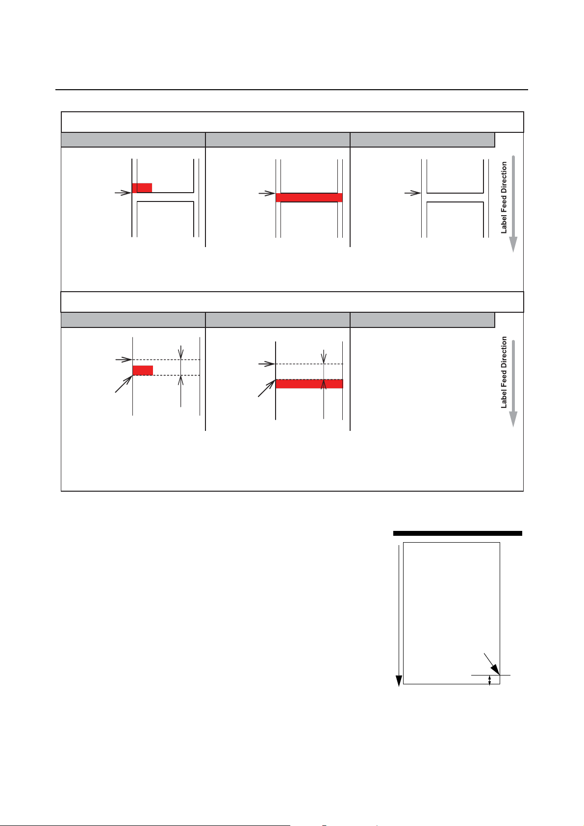
Section 8: Appendix
8.5 BASE REFERENCE POINT (cont’d)
Dispenser Mode
I-Mark I-Mark (CX-compatible)
Base print
and dispense
position
7KHVWDUWRI,0DUNLVWKHEDVHSULQWDQGGLVSHQVHSRVLWLRQZKHQXVLQJWKH,0DUNVHQVRU
7KHHQGRI,0DUNLVWKHEDVHSULQWDQGGLVSHQVHSRVLWLRQZKHQXVLQJWKH,0DUN&;FRPSDWLEOHVHQVRU
7KHHQGRIODEHO*DSLVWKHEDVHSULQWDQGGLVSHQVHSRVLWLRQZKHQXVLQJWKHODEHO*DSVHQVRU
Base print
and dispense
position
Base print
and dispense
position
Gap
/LQHUOHVV1RQ6HSD0RGH
I-Mark I-Mark (CX-compatible)
Base print
position
%DVHPDQXDO
FXWSRVLWLRQ
Unprintable
area (mP
´
Base print
position
%DVHPDQXDO
FXWSRVLWLRQ
Unprintable
area (mP
´
,Q/LQHUOHVV1RQVHSDPRGHWKHODEHOZLOOJHWFDXJKWLQWKHSODWHQUROOHUE\PRYLQJWKHODEHOEDFNWR
WKHSULQWKHDGSRVLWLRQ7KHUHIRUHWKHDPRXQWRIEDFNIHHGLVGHFUHDVHGWRVWRSWKHODEHOWRSIURP
PRYLQJEDFNWRWKHSULQWKHDGSRVLWLRQ1RWHWKDWWKHODEHOZLOOKDYHDPP´XQSULQWDEOHDUHD
ZKLFKLVWKHGHFUHDVHGDPRXQWRIEDFNIHHG
8.5.1 Base Reference point Adjustment
Print Position Offset refers to the vertical and horizontal shifting of the
entire print area, relative to the start position of printing (V=0, H=0),
defined by default to be the bottom right hand corner of the label.
The Base Reference point can be adjusted by using the Printer Utilities
Tool application or by sending the <A3> command from the host.
The V setting is for the Vertical print offset. A positive (+) offset means
the printing is shifted towards the print head; a negative (-) offset means
shifting away from the print head.
The H setting is for the Horizontal print offset. The + or - prefix
determines whether the offset is to the left or to the right of the reference
point.
The default value of both positions is +000 dot. The maximum values that
can be set for each is +/-792 dot.
You may wish to make a test print after completing the adjustments to
ensure they are correct. Refer to
Section 3.3 User Test Print Mode for details.
direction of label motion
Print offset
Print head
H+V-H-
ref point 0,0
V+
Page 8-8
LD610 User’s Technical Reference
Page 97
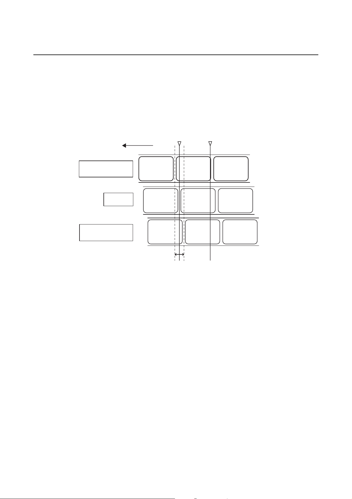
Section 8: Appendix
8.6 OFFSET POSITION ADJUSTMENT
This setting adjusts the option (Cutter, Dispenser, Tear off) stop position after a print out.
The Offset position can be adjusted by using OKI Utilities Tool application or by sending command <PO> from
the host. The setting range is within ±99 dots. A positive value moves the leading edge of the label forward
(away from the print head) while a negative value moves the leading edge of the label back toward the
mechanism.
Adjustment of Offset setting
Stop position for
Label feed direction
Adjustment for
“+” direction
No
Adjustment
cutting,dispense
or tear-off
Base reference
position for printing
Adjustment for
“-” direction
-99 (dot)+99 (dot)
LD610 User’s Technical Reference Page 8-9
Page 98
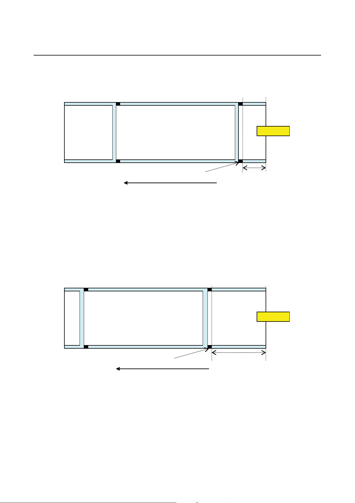
Section 8: Appendix
8.7 PAPER END
8.7.1 Roll Label End
When the Label End is less than 40mm (1.57”) from the end of I-Mark
(1)
I-Mark
Media feed direction
The printer behavior when paper end is detected is as follows:
• After completing the print of label (1), “Paper end error” will occur.
• In cutter mode, “Paper end error” will occur after cutting the label.
• After releasing the error, Label (1) will not be printed again.
(2)
Approximately
40mm (1.57”) or
less
Note:
The paper end detection is performed by the I-Mark sensor, therefore, the above motion may not occur
depending on the adjustment of the I-Mark sensor.
When the Label End is More Than 40mm (1.57”) from the end of I-Mark
(1)
I-Mark
(2)
Approximately 40mm
(1.57”) or more
Media feed direction
The printer behavior when paper end is detected is as follows:
• “Paper end error” will occur while printing the label (2).
• If an error occurs while printing, label (2) will be printed again after releasing the error. If the print job is
completed at the time of error occurrence, label (2) will not be printed again.
• In cutter mode, cutting motion will not occur when the printer has a “Paper end error.”
Note:
The paper end detection is performed by the I-Mark sensor, therefore, the above motion may not occur
depending on the adjustment of the I-Mark sensor.
Page 8-10
LD610 User’s Technical Reference
Page 99
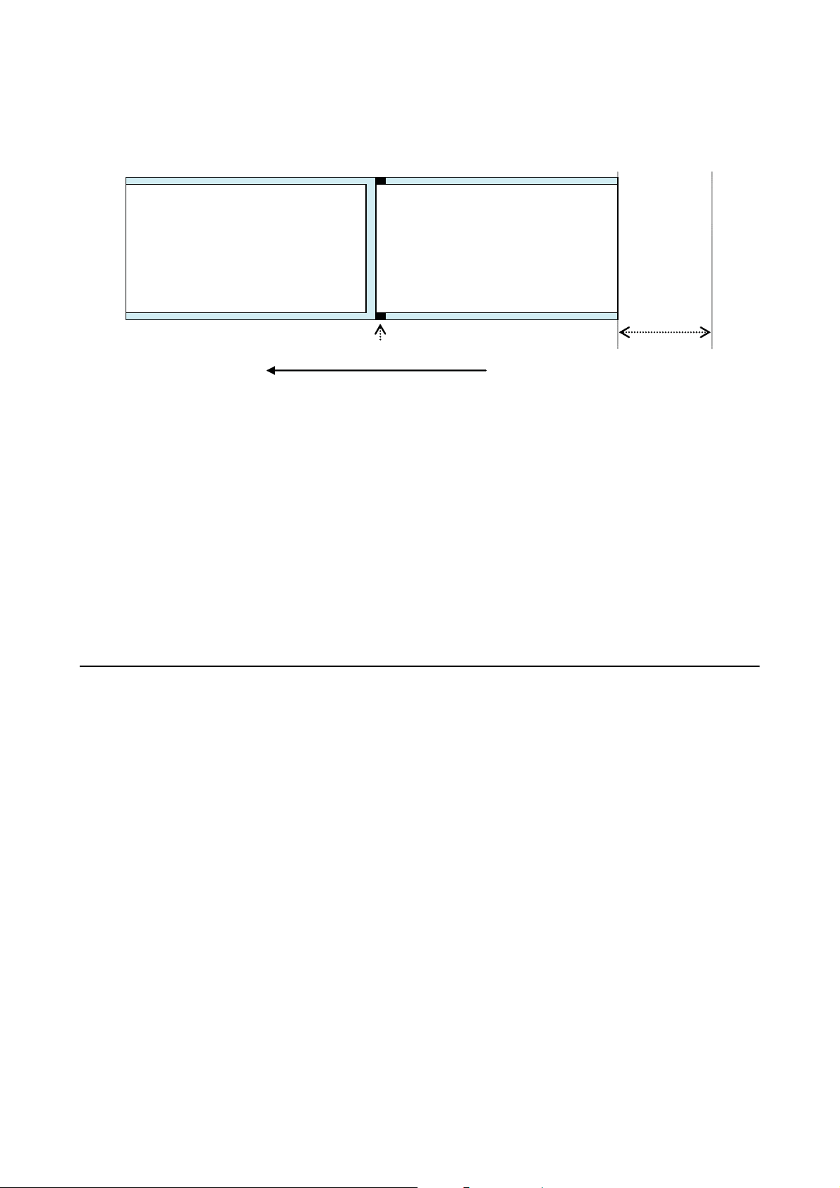
8.7.2 Fanfold Label End
Section 8: Appendix
(1)
I-Mark
(2)
Feeds 50mm
(2”)
Media feed direction
The printer behavior when paper end is detected is as follows:
• After printing and feeding label (2) 50mm (2”), “Paper end error” will occur.
• If an error occurs while printing, label (2) will be printed again after releasing the error. If the print job is
completed at the time of error occurrence, label (2) will not be printed again. (Also, when the print job is
completed while feeding the label 50mm (2”), the label will not be reprinted.)
• In cutter mode, cutting motion will not occur when the printer has a “Paper end error.”
Note:
The paper end detection is performed by the I-Mark sensor, therefore, the above motion may not occur
depending on the adjustment of the I-Mark sensor.
8.8 RIBBON END
Ribbon End detection is only available for LD610 T printers.
Printer behavior when ribbon near end is detected is as follows:
• Ribbon near end can be detected by setting printing method to thermal transfer.
• When the ribbon remaining becomes 5 to 7m (16.4 ft. to 22.9 ft.), “Ribbon near end” will be detected.
The status of ribbon near end will be returned if status request (ENQ) is made.
Printer behavior when ribbon end is detected:
• Ribbon end can be detected by setting printing method to thermal transfer.
• If the print job is completed at the time of “Ribbon end error”, the label will not be printed again after
releasing the error.
• If “Ribbon end error” occurs while printing, the label will be printed again after releasing the error.
LD610 User’s Technical Reference Page 8-11
Page 100

Section 8: Appendix
This page is intentionally left blank
Page 8-12
LD610 User’s Technical Reference
 Loading...