

Page 1
Page 2

PREFACE
Ev ery ef for t ha s be en m ade to ens ure tha t th e in for ma tio n in thi s do cum en t is com ple te,
accurate, and up-to-date. Oki assumes no respons ibility for the results o f errors beyond
its control. Oki also cannot guarantee that changes in softwar e and equipment made by
other manufacturers and referred to in this guide will not affect the applicability of the
information in it. Mention of software products manufactured by other companies does
not necessarily constitute endorsement by Oki.
While all reasonable efforts have been made to make this document as accurate and
helpful as possible, we make no warranty of any kind, expressed or implied, as to the
accuracy or completeness of the information contained herein.
For latest information please see the Oki Europe website:
http://www.okieurope.com
07043201 First edition 05/2003.
Copyright 2003 by Oki. All rights reserved.
Oki is a registered trademark of Oki Electric Industry Company Ltd.
Microsoft, MS-DOS and Windows are registered trademarks of Microsoft Corporation.
This product complies with the requirements of the Council
Directives 89/336/EEC (EMC) and 73/23/EEC (LVD) as amended
where applicable on the approximation of the laws of the member
states relating to electromagnetic compatibility and low voltage.
WARNING!
This is a Class A product. In a domestic environment this product may cause radio
interference, in which case the user may be required to take adequate measures.
2 < PREFACE
Page 3

CONTENTS
Preface .......................................................................... 2
Introduction................................................................... 7
How to use this Guide..................................................... 8
Identifying component items .......................................... 9
Finisher .................................................................... 9
Overall configuration............................................... 10
Using the Finisher ........................................................ 12
Before you begin ..................................................... 12
General.............................................................. 12
Stacker summary information............................. 12
Punching information ......................................... 13
Stapling information ..........................................15
Job offset information......................................... 17
Printing and “finishing” a document ........................ 18
Printer control panel settings.............................. 18
Setting your printer driver .................................. 19
Windows drivers ................................................ 21
Macintosh drivers .............................................. 33
Troubleshooting........................................................... 39
Counteracting paper curl ......................................... 39
Clearing a paper jam ............................................... 41
Removing jammed staples....................................... 48
Maintaining the Finisher...............................................52
Replenishing the staple cartridge unit...................... 53
Removing the punch chips....................................... 58
Appendix A - Specification............................................ 61
Main characteristics................................................ 61
Configuration diagram ....................................... 62
Appendix B - Paper feed and ejection details................. 63
Printer paper feed details........................................ 63
Paper ejection details.............................................. 65
Finisher Face Up stacker..................................... 65
Finisher Face Down stacker................................. 67
Printer Face Down stacker .................................. 68
Appendix C - Error and warning messages..................... 70
English
CONTENTS > 3
Page 4

Appendix D - Consumables ........................................... 71
Staples ................................................................... 71
Oki Contact Details....................................................... 73
Index ........................................................................... 75
4 < CONTENTS
Page 5

English
NOTES, CAUTIONS & WARNINGS
NOTE
A note appears in this manual like this. A note provides additional
information to supplement the main text which may help you to use and
understand the product.
CAUTION!
A caution appears in this manual like this. A caution provides
additional information which, if ignored, may result in equipment
malfunction or damage.
WARNING!
A warning appears in this manual like this. A warning provides
additional information which, if ignored, may result in a risk of
personal injury.
Only use genuine Oki Original consumables to ensure the best quality
and performance from your hardware. Non Oki Original products may
damage your printer's performance and invalidate your warranty.
Specifications subject to change without notice. All trademarks
acknowledged.
NOTES, CAUTIONS AND WARNINGS > 5
Page 6

6 < NOTES, CAUTIONS AND WARNINGS
Page 7

INTRODUCTION
The C9300/C9500 Finisher option adds document production
functionality to the C9300/C9500 colour printers by providing:
l on-line stapling
l on-line punching
l paper position offset capability for job and copy unit (collated
printing) separation
For use with the Finisher, the printer requires a total of five paper trays
and the Finisher is positioned on a Finisher Cabinet so that it aligns
with the printer paper output path.
NOTE
This document assumes that the Finisher has been mechanically
installed.
English
INTRODUCTION > 7
Page 8

HOW TO USE THIS GUIDE
This User’s Guide describes the C9300/C9500 Finisher. The printer
and Finisher Cabinet are described in separate documents.
The contents of this Guide are arranged to take you through the
following steps to make the best use of the Finisher:
l Being aware of safety issues
l Setting up the printer driver
l Using the Finisher
l Troubleshooting the Finisher
l Maintaining the Finisher
You are advised to read the sections of this document in the order in
which they are presented. Once you are familiar with the equipment
you can refer to specific sections in isolation via the Table of Contents
or Index.
8 < HOW TO USE THIS GUIDE
Page 9
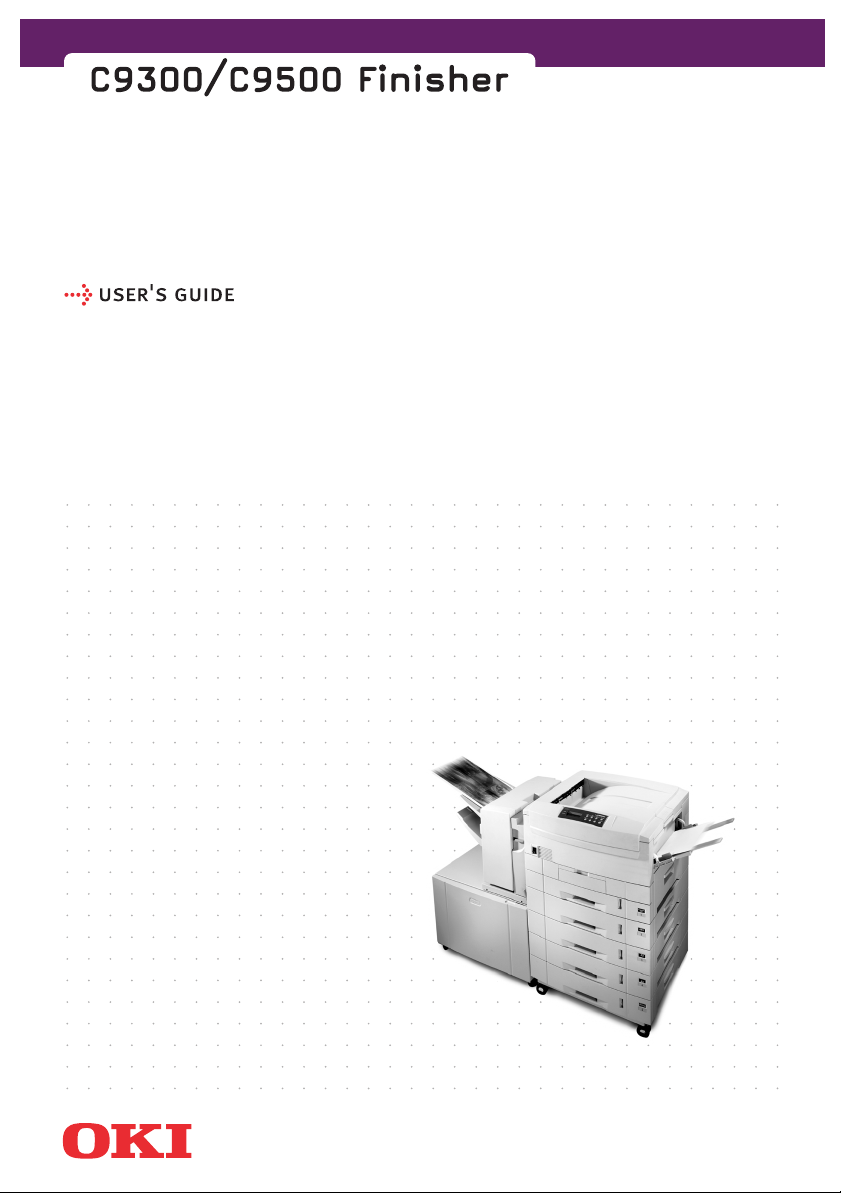
IDENTIFYING COMPONENT ITEMS
FINISHER
The component parts of the Finisher identified in the following
diagram are referred to as:
3
2
4
1
5
6
English
Face Down Stacker
1.
Face Up Stacker
2.
Finisher Cover
3.
Decurler Lever
4.
7
8
9
10
IDENTIFYING COMPONENT ITEMS > 9
Page 10
Release Lever
5.
Finisher Guide
6.
Finisher Entry Plate
7.
Chip Box (to catch the small circular paper punchings
8.
produced when the paper is punched)
Staple Unit
9.
Staple Cover
10.
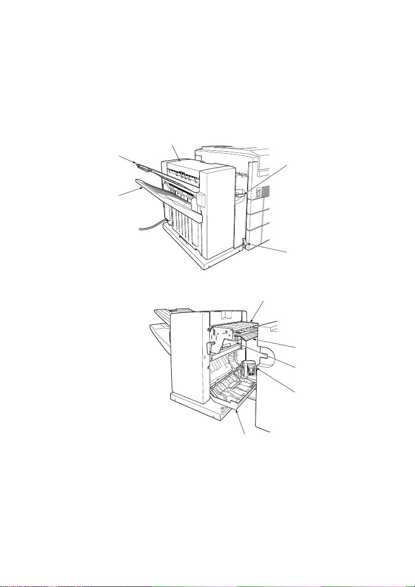
OVERALL CONFIGURATION
l For compatibility with the Finisher, the printer requires both a
second tray and an additional high capacity feed paper tray
unit. A Finisher Cabinet is required to support the Finisher.
1
2
CAUTION!
To avoid possible damage to the Finisher as the Face Down Stacker (1)
moves upwards or downwards, do not place any objects in the shaded
area (2) at any time.
10 < IDENTIFYING COMPONENT ITEMS
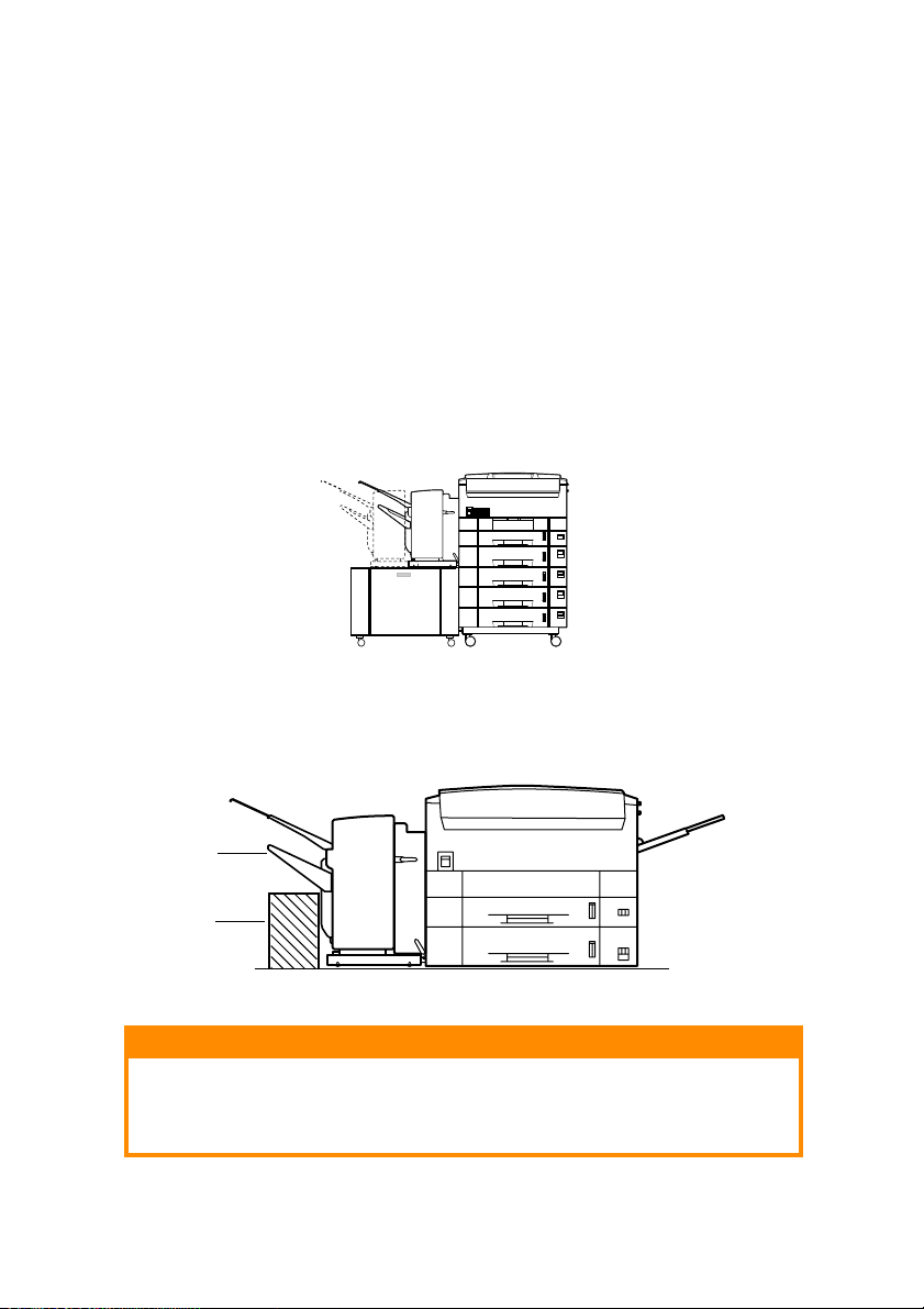
Page 11

English
When carrying out troubleshooting or maintenance work on the
Finisher, it can be detached from the printer.
l Paper trays are numbered from top to bottom:
Trays 1, 2, 3, 4, and 5 (where Tray 1 is the original tray supplied
with the printer, Tray 2 is the additional second tray and Trays
3 through 5 are part of the additional high capacity feed paper
tray unit).
NOTE
For simplicity, many of the illustrations in this manual do not show the
Finisher Cabinet.
IDENTIFYING COMPONENT ITEMS > 11
Page 12

USING THE FINISHER
BEFORE YOU BEGIN
The Finisher can handle only certain sizes, weights and types of media
in its punching, stapling and offsetting operations. Refer to the
following summary information to help you ensure that you make
correct use of the Finisher.
For detailed information, see “Appendix A - Specification” and
“Appendix B - Paper feed and ejection details”.
GENERAL
When the Finisher is being used:
l Custom width is 100 to 297mm and length is 149 to 1200mm.
Paper size must be set to Portrait.
l Envelope 1 (Portrait No 3), Envelope 2 (Portrait No 4), Envelope
3 (Landscape No 4), Com-9, Com-10, DL, C4 and Monarch
envelopes cannot be used.
l Error and warning messages that appear on the printer control
panel display are given in “Appendix C - Error and warning
messages”.
STACKER SUMMARY INFORMATION
TACKER
S
Face up (upper stacker)
Face down (lower stacker)
EATURES
F
Capacity: 100 sheets (at 80g/m
Size: A6 to A3
Punching, short or long side
Capacity: 1000 sheets (at 80g/m2)
Size: A4, Letter
Punching, long side
Stapling
Offsetting for job or copy unit separation
12 < USING THE FINISHER
2
)
Page 13

PUNCHING INFORMATION
Allowable paper sizes
For long-side binding:
l A4 (landscape) - 2-hole or 4-hole
l Letter (landscape) - 2-hole or 4-hole
l B5 (landscape) - 2-hole or 4-hole
For short side binding:
l A4 (portrait) - 2-hole
l Letter (portrait) - 2-hole
l B5 (portrait) - 2-hole
l Custom (width: 100 to 297mm, length: 149 to 1200mm)
(portrait) - 2-hole or 4-hole
l A3 (portrait) - 2-hole or 4-hole
l A5 (portrait) - 2-hole
l A6 (portrait) - 2-hole
English
l B4 (portrait) - 2-hole or 4-hole
l Legal (13in, 13.5in, 14in) (portrait) 2-hole
l Executive (portrait) - 2-hole
l Tabloid (portrait) - 2-hole or 4-hole
Allowable paper weight
l Upper tray (face up): 64 to 200g/m
2
104g/m
can be punched).
l Lower tray (face down): 64 to 104g/m
2
(only paper weights up to
2
, can be punched and
stapled.
l Post card, Envelope, Label stationery and OHP sheets cannot
be punched.
USING THE FINISHER > 13
Page 14
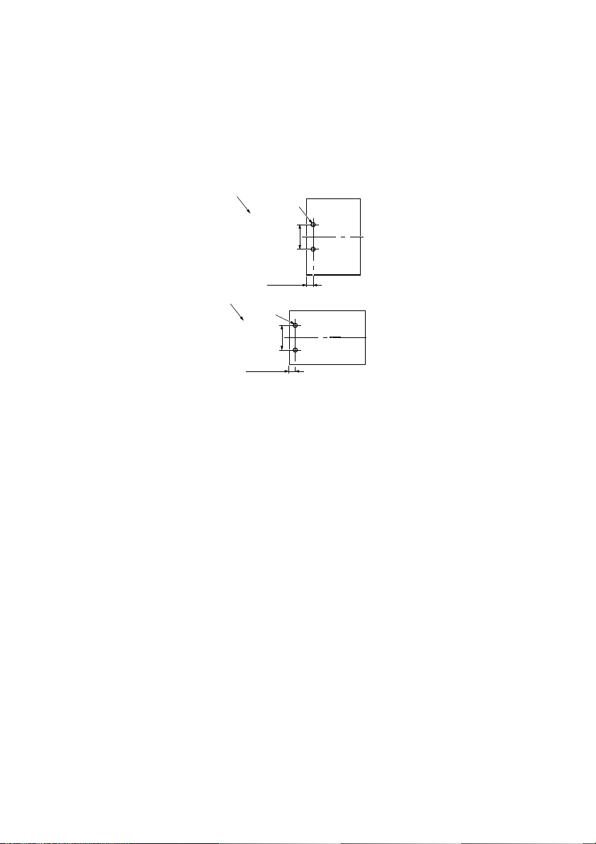
Hole positions
The Finisher is supplied with either 2-hole or 4-hole punching
capability.
The hole positions are shown below for 2-hole long-side binding (1)
and short-side binding (2):
1
f6+/-0.5mm
80+/-0.5mm
10.5+/-1mm
2
f6+/-0.5mm
80+/-0.5mm
10.5+/-1mm
l For 4-hole punching, two additional holes of the same
diameter are added, spaced 80+/-5mm on either side of the 2-
hole punching holes.
l Although punching always takes place at the same position on
the paper, by selecting paper orientation (portrait, landscape
or landscape with 180 deg rotation of printed data) in the
printer driver, the holes can effectively be placed at the left
side of a document for portrait use or at the top side or bottom
side of a document for landscape use.
Punching procedure
l Each sheet is punched individually.
14 < USING THE FINISHER
Page 15

English
STAPLING INFORMATION
Allowable paper sizes
l A4 (landscape)
l Letter (landscape)
Allowable paper weight
2
l Only normal paper of weight 64 to 104g/m
l Post card, Envelope, Label stationery and OHP sheets cannot
be stapled.
l Maximum paper per staple is 30 sheets or 3mm total
thickness. The number of sheets that can be stapled for
different paper weights is:
can be used.
APER WEIGHT
P
64 to 74g/m
75 to 90g/m
91 to 104g/m
2
2
2
UMBER OF SHEETS
N
30
25
22
l Face Down stacker full detection occurs when a maximum
number of stapled sets is reached (for example, 50 sets at 10
sheets per set). The printer control panel message is:
COULD NOT STAPLE. TOO MUCH PAPER
(See “Appendix C - Error and warning messages”.)
l Paper of weight greater than
104g/m2 is ejected without being
stapled.
USING THE FINISHER > 15
Page 16

Staple position
The staple (1) position is shown below:
6+/-2mm
6+/-2mm
1
l Although stapling always takes place at the same position on
the paper, by selecting paper orientation (portrait, landscape
or landscape with 180 deg rotation of printed data) in the
printer driver, the staple can effectively be placed at top left of
a document for portrait use or top right or bottom left of a
document for landscape use.
Stapling procedure
l Stapling is by print job or by copy unit.
l When stapling is enabled, single-sheet print jobs or copy units
are stapled.
l If paper sizes of A4 (landscape) and Letter (landscape) are
mixed in one print job, stapling will take place. Any other
paper size mixes will not be stapled and the paper will be
ejected to another stacker.
16 < USING THE FINISHER
Page 17

English
JOB OFFSET INFORMATION
Allowable paper sizes
l A4 (landscape)
l Letter (landscape)
Job offset position
Successive jobs are offset from each other by nominally 23mm (in a
direction orthogonal to paper travel).
Job offset procedure
l Job offset cannot be done along with stapling.
l Job offset is by print job or by copy unit.
USING THE FINISHER > 17
Page 18

PRINTING AND “FINISHING” A DOCUMENT
NOTE
This section deals only with additional settings required for Finisher
usage. Refer to your printer User’s Manual for other control panel and
printer driver settings such as paper source, type and size.
PRINTER CONTROL PANEL SETTINGS
For details on making settings at the printer control panel, refer to
your printer User’s Manual.
The additional functions associated with the Finisher that are
available on the printer control panel are accessed via:
l The PRINT MENU
l The LIFE SPAN MENU
PRINT MENU options
NOTE
Settings made from an application via the printer driver override the
following settings.
Output bin
Output bin: Set to define where to eject paper
Output binOutput bin
Standard bin
Standard bin: ejects to printer face down stacker at the top of
Standard binStandard bin
the printer (default setting)
Option bin 1
Option bin 1: ejects to Finisher face up stacker
Option bin 1Option bin 1
Option bin 2
Option bin 2: ejects to Finisher face down stacker
Option bin 2Option bin 2
Punching
Punching: Set to enable or disable punching
PunchingPunching
Off
Off: disables punching (default setting)
OffOff
On
On: enables punching
OnOn
Stapling
Stapling: Set to enable or disable stapling
StaplingStapling
Off
Off: disables stapling (default setting)
OffOff
18 < USING THE FINISHER
Page 19

English
On
On: enables stapling
OnOn
LIFE SPAN MENU options
Stapling count
Stapling count: displays the number of staples used in the format
Stapling countStapling count
nnnnnn (a 6-digit number)
Punching count
Punching count: displays the number of punch operations made in
Punching countPunching count
the format nnnnnn (a 6-digit number)
Finisher count
Finisher count: displays the number of sheets ejected to the Finisher
Finisher countFinisher count
in the format nnnnnn (a 6-digit number)
SETTING YOUR PRINTER DRIVER
The operating systems supported are as follows:
PostScript printing: Windows 95, 98, Me, 2000, NT4, XP, Macintosh
PCL printing: Windows 95, 98, Me, 2000, NT4, XP.
NOTE
The following instructions explain the driver settings involved to use the
Finisher. Other settings are explained in your printer User’s Manual.
Finisher-related settings
The settings you have to make for the Finisher are to:
Define that the Finisher is installed.
1.
Define the number of paper trays installed (a total of 5, i.e. 1
2.
original tray, 1 additional tray and 1 high capacity feed unit).
Define the paper orientation (Portrait, Landscape or
3.
Landscape with 180 deg rotation of printed data) to suit your
punching and/or stapling requirements.
ROTATION
NO
Portrait Staple top left
Punch left hand side
Landscape Staple top right
Punch top side
USING THE FINISHER > 19
DEG ROTATION
180
Not applicable
Staple bottom left
Punch bottom side
Page 20

Define the punching and/or stapling requirements (None,
4.
Staple, Staple + Punch (Long Edge), Punch (Long Edge), Punch
(Short Edge)).
NOTE
A graphic on some driver windows illustrates where punching and/or
stapling is located on the finished document to assist you in making
these settings.
Define where the finished documents are ejected:
5.
Stacker (Face-down)
Stacker (Face-down): paper is ejected at the top of the
Stacker (Face-down)Stacker (Face-down)
printer
Finisher (Face-up)
Finisher (Face-up): paper is ejected to the upper
Finisher (Face-up)Finisher (Face-up)
stacker of the Finisher
Finisher (Face-down)
Finisher (Face-down): paper is ejected to the lower
Finisher (Face-down)Finisher (Face-down)
stacker of the Finisher.
NOTE
An error message is displayed if an inappropriate combination of paper
size, stapling, punching, output destination has been selected.
20 < USING THE FINISHER
Page 21
WINDOWS DRIVERS
Windows 95/98/Me
Use [Start]-[Settings]-[Printers] to show the [Printers] window.
1.
Right click on the required printer and click [Properties] in the
2.
pop-up menu to show the Properties window.
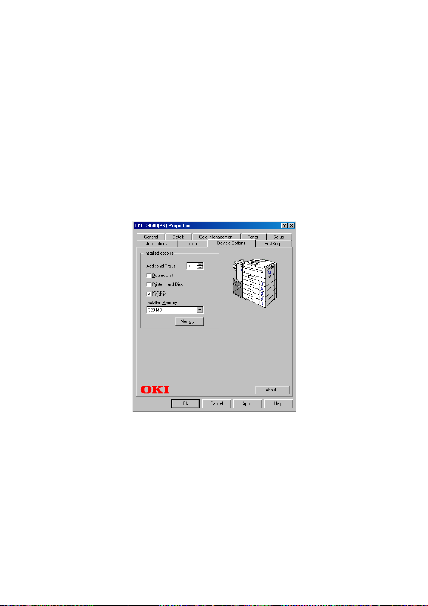
For PostScript printer driver:
3.
Click on the [Device Options] tab.
(a)
In [Additional Trays] select your tray configuration.
(b)
Check the [Finisher] checkbox then click [Apply].
(c)
English
USING THE FINISHER > 21
Page 22
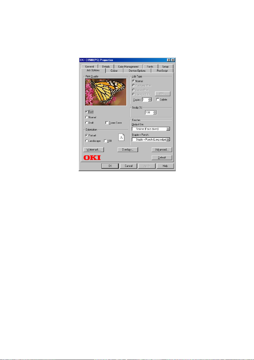
Click the [Job Options] tab, select the required [Output
(d)
bin], paper [Orientation] and stapling/punching
arrangement then click [Apply].
Click [OK] to close the driver user interface.
(e)
22 < USING THE FINISHER
Page 23
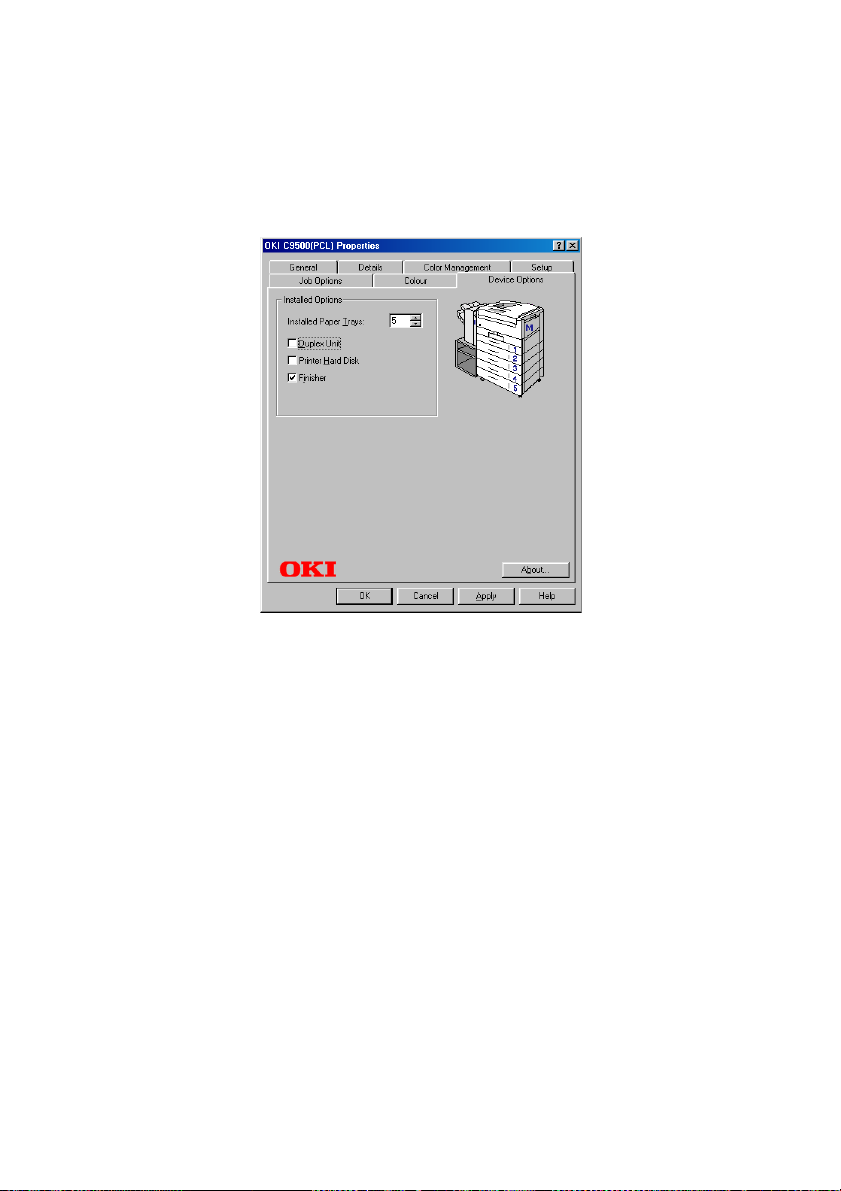
For PCL printer driver:
4.
(a)
(b)
English
Click on the [Device Options] tab.
Set the number of [Installed Paper Trays], check the
[Finisher] checkbox then click [Apply].
USING THE FINISHER > 23
Page 24

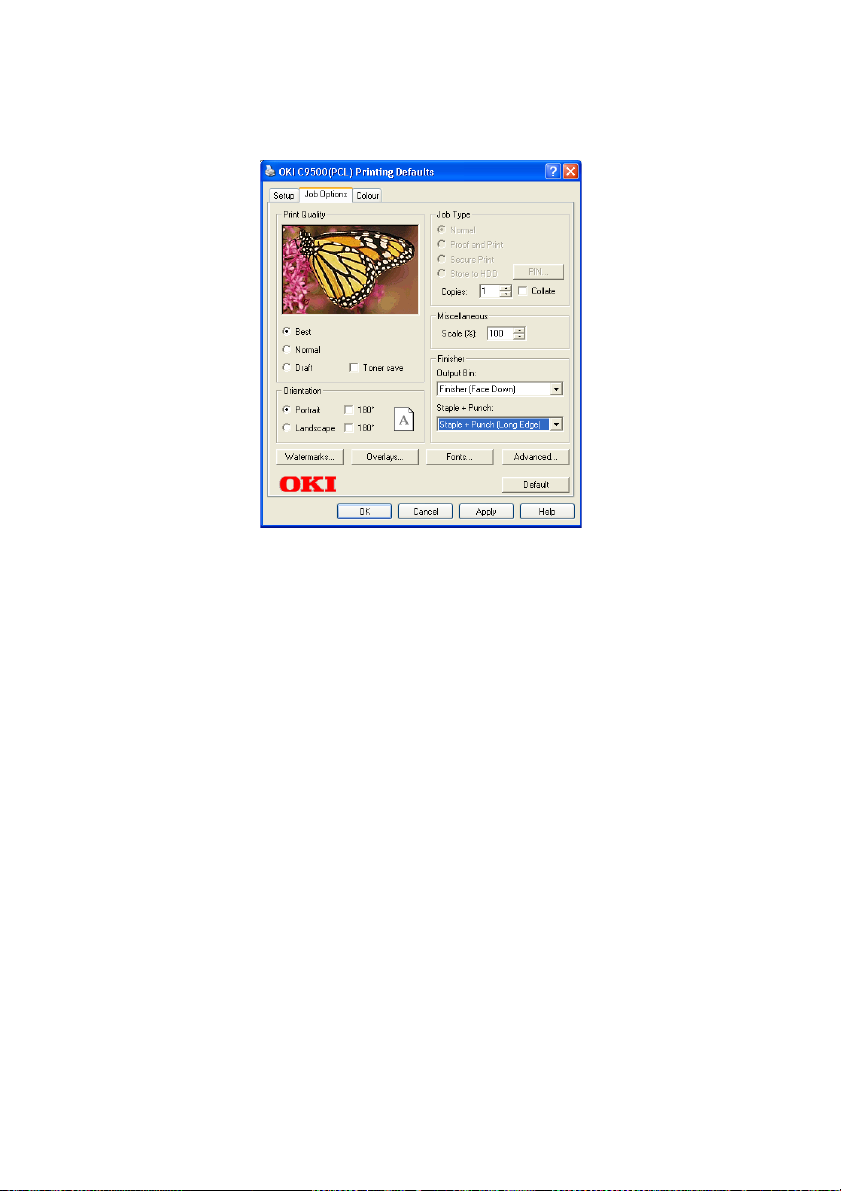
Click the [Job Options] tab, select the required [Output
(c)
bin], paper [Orientation] and stapling/punching
arrangement then click [Apply].
Click [OK] to close the driver user interface.
(d)
24 < USING THE FINISHER
Page 25

Windows 2000/XP (XP shown)
Use [Start]-[Settings]-[Printers/Printers and Faxes] to show the
1.
[Printers] window.
Right click on the required printer and click [Properties] in the
2.
pop-up menu to show the Properties window.
For PostScript printer driver:
3.
Click on the [Device Settings] tab.
(a)
English
Highlight [Finisher], then select [Installed].
(b)
Highlight [AvailableTray], select the number installed
(c)
and click [Apply].
USING THE FINISHER > 25
Page 26

Click [OK] to close the Properties dialog. Right click on
(d)
the printer icon and choose [Printing Preferences...].
On the [Layout] tab, select the required paper
(e)
[Orientation] and click [Apply].
Click the [Job Options] tab, select the required [Output
(f)
bin] and stapling/punching arrangement then click
[Apply].
26 < USING THE FINISHER
Page 27

(g)
For PCL printer driver:
4.
(a)
(b)
English
Click [OK] to close the driver user interface.
Click on the [Device Options] tab.
Set the number of [Installed Paper Trays], check the
[Finisher] checkbox then click [Apply].
USING THE FINISHER > 27
Page 28
Click on the [Advanced] tab the [Printing Defaults]
(c)
button then click on the [Job Options] tab.
Select the required paper [Orientation], [Output bin] and
(d)
stapling/punching arrangement then click [Apply].
Click [OK] twice to close the driver user interface.
(e)
28 < USING THE FINISHER
Page 29

Windows NT4.0
Use [Start]-[Settings]-[Printers] to show the [Printers] window.
1.
For PostScript printer driver:
2.
Right click on the required printer and click [Properties]
(a)
in the pop-up menu to show the Properties window.
Click on the [Device Settings] tab.
(b)
English
Highlight [Finisher] and select [Installed] from the list.
(c)
Highlight [Available Tray], then select the number
(d)
installed (i.e. 5) and click [OK].
USING THE FINISHER > 29
Page 30

Right click on the required printer and click [Document
(e)
Defaults...] in the pop-up menu to show the Default
window then click on the [Job Options] tab.
Select the required paper [Orientation], [Output bin] and
(f)
stapling/punching arrangement.
Click [OK] to close the driver user interface.
(g)
30 < USING THE FINISHER
Page 31

For PCL printer driver:
3.
(a)
(b)
English
Right click on the required printer and click [Properties]
in the pop-up menu to show the Properties window.
Click on the [Device Options] tab. Set the number of
[Installed Paper Trays], check the [Finisher] checkbox
and then click [OK].
USING THE FINISHER > 31
Page 32

Right click on the required printer and click [Document
(c)
Defaults...] in the pop-up menu to show the Default
window then click on the [Job Options] tab.
Select the required paper [Orientation], [Output bin] and
(d)
stapling/punching arrangement.
Click [OK] to close the driver user interface.
(e)
32 < USING THE FINISHER
Page 33

MACINTOSH DRIVERS
Macintosh (Mac OS)
Open the Chooser from the Apple menu.
1.
Depending on the driver you use, select either the AdobePS or
2.
LaserWriter 8 icon on the left-hand side of the Chooser. Click
on the [Setup...] button.
English
Click on [Configure].
3.
Change [Available Tray] to the required value.
4.
Change [Finisher] to [Installed].
5.
USING THE FINISHER > 33
Page 34

Click [OK] twice.
6.
Click [File] then [Page Setup...]. On the [Page Attributes] panel,
7.
set the page [Orientation] and on the [PostScript Options]
panel set the Visual Effects controls as required.
C9500
8.
C9500
Click [OK].
34 < USING THE FINISHER
Page 35

Click [File] and then click the application Print menu.
9.
On the [Printer Job Options] panel, set the required [Output
10.
Bin] option and [Staple & Punch] option.
Click [Save Settings].
11.
Macintosh (Mac OSX)
Mac OS X versions 10.1 - 10.1.5
English
For older versions of Mac OS X, it is not possible to manually change
the printer installable options. However, all of the printer options are
enabled by default in the PostScript Printer Description (PPD) file for
your printer. This may lead to some inappropriate options becoming
available for your printer model.
If you are using Mac OS X 10.1 - 10.1.5, please ignore Steps 1 to 7
below, and start at Step 8.
Mac OS X version 10.2 and greater
Launch the [Print Center] application which is located in the
1.
[Applications : Utilities] folder.
USING THE FINISHER > 35
Page 36

Select your printer from the list, and from the [Printers] menu
2.
select [Show Info].
From the pop-up menu, choose [Installable Options].
3.
Change [Available Tray] to the required value.
4.
Select the [Finisher] option.
5.
Click [Apply Changes].
6.
36 < USING THE FINISHER
Page 37

From the [Print Center] menu, select [Quit Print Center].
7.
From inside your application program, click [File] then [Page
8.
Setup].
From the [Format for:] menu, select your printer.
9.
Set the paper [Orientation] as required.
10.
English
11.
Click [OK].
USING THE FINISHER > 37
Page 38

Click [File] then [Print].
12.
On the [Printer Features] panel, set the required [Output Bin]
13.
and [Staple & Punch] options.
From the [Presets] menu, choose [Save As…] to save the
14.
settings as default.
38 < USING THE FINISHER
Page 39

TROUBLESHOOTING
For a full list of error and warning messages, refer to “Appendix C Error and warning messages”.
COUNTERACTING PAPER CURL
If the paper emerging from the Finisher displays significant curl (1) it
might not stack properly. Also, curled paper might cause jams to
occur in the Finisher.
1
To counteract such curl, you can adjust the position of the Decurler
Lever.
English
TROUBLESHOOTING > 39
Page 40

Setting the Decurler Lever
1.
Confirm that the Decurler Lever (1) is in the horizontal
(a)
position i.e. the setting for normal operation.
To counteract the curl, rotate the Decurler Lever
(b)
upwards as far as it will go.
1
1
NOTE
Depending on the direction and magnitude of paper curl, it is possible
that setting the Decurler Lever as above might cause a paper jam or
stacking error to occur. In this event, return the Decurler Lever to its
horizontal position.
40 < TROUBLESHOOTING
Page 41

CLEARING A PAPER JAM
When a paper jam occurs, the following message appears on the
printer control panel:
REMOVE FINISHER
nnn: PAPER JAM
where nnn is in the range 361 to 367.
NOTES
> Paper may be jammed in both the printer and the Finisher. For
details of clearing a paper jam in the printer, refer to the printer
User’s Manual.
> When a printer paper jam is cleared, recovery printing will reprint
the pages that were jammed. Provided the first page of a set to be
stapled is reprinted, stapling will take place: otherwise, the paper
will be ejected without stapling.
> When a Finisher unit paper jam is cleared, the pages that were
jammed will not be automatically reprinted. Remaining pages of a
set that was to be stapled will be ejected without stapling.
English
TROUBLESHOOTING > 41
Page 42

Use the paper jam identifying number on the printer display to
1.
locate the paper jam in the Finisher.
NOTE
The number (in the range 361 to 367 inclusive) identifies the first
position at which paper is jammed. If the paper is jammed in several
places, another number may be displayed after removing the jam at the
first location.
366
367
7
363
364
362
1
2
365
6
361
4
3
5
42 < TROUBLESHOOTING
Page 43

Detach the Finisher.
2.
WARNING!
Do not touch the Finisher Guide (2) as it may be hot.
Rotate the Decurler Lever (1)
(a)
to point downwards.
Rotate the Release Lever (3)
(b)
upwards and detach the
Finisher from the printer.
English
2
1
3
TROUBLESHOOTING > 43
Page 44
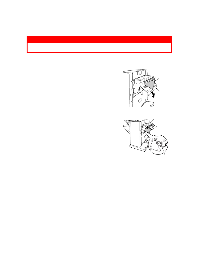
Remove the jammed paper.
3.
WARNING!
Be careful to avoid components and edges inside the Finisher.
Locations 361 and 362
Hold down the Finisher Entry
(a)
Plate (2) and remove the
paper (1).
Hold down the Loop Guide
(b)
(4) and remove the paper (1).
Raising the Finisher Guide
(3) may make the paper
removal easier.
1
2
3
1
4
44 < TROUBLESHOOTING
Page 45
Locations 363 and 364
Hold up the Finisher Guide (1)
(c)
and carefully remove the Chip
Box (2). (You can empty the Chip
Box when you have removed it.)
English
1
Open the Staple cover (3).
(d)
Rotate the blue knob (4)
(e)
located in the Finisher
Guide in the direction of the
arrow and remove the
paper when it appears.
Raise and hold the blue
(f)
Guide Plate (5) in the
Finisher Guide and
remove the paper.
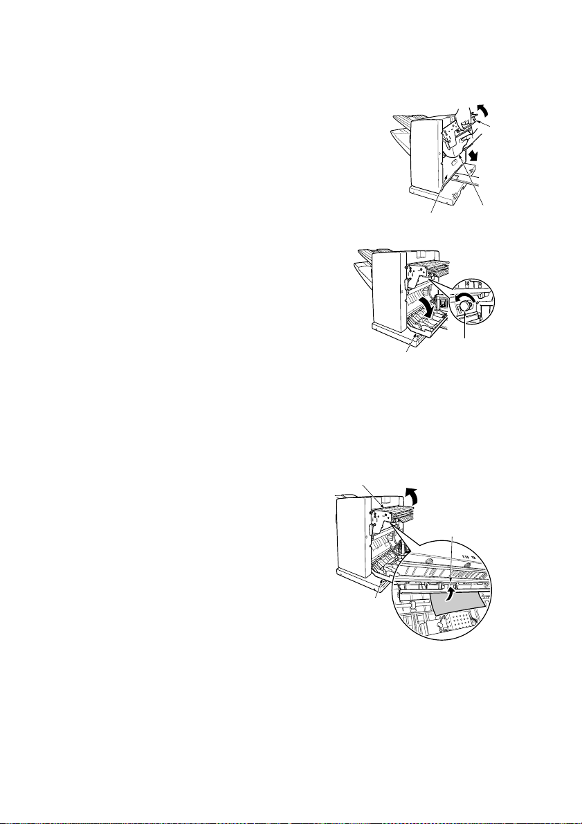
Raise and hold the
(g)
Finisher Guide (1) and
refit the Chip Box.
Close the Staple Cover
(h)
(3).
3
3
1
3
2
4
5
TROUBLESHOOTING > 45
Page 46

Locations 365 and 367
Open the Staple Cover
(i)
(2) and remove the
paper (3). Paper
removal may be easier
if you rotate the blue
knob (1) in the direction
of the arrow.
Close the Staple Cover
(j)
(2).
Location 366
Open the Finisher Cover (1)
(k)
and remove the paper (2).
Close the Finisher Cover (1).
(l)
1
23
1
2
46 < TROUBLESHOOTING
Page 47

Attach the Finisher to the printer.
4.
Push the Finisher towards the printer until it clicks into
(a)
position.
Return the Decurler Lever (1) to the horizontal position.
(b)
English
1
NOTE
If the Decurler Lever is not returned to the horizontal position, it may
cause the paper to jam.
TROUBLESHOOTING > 47
Page 48

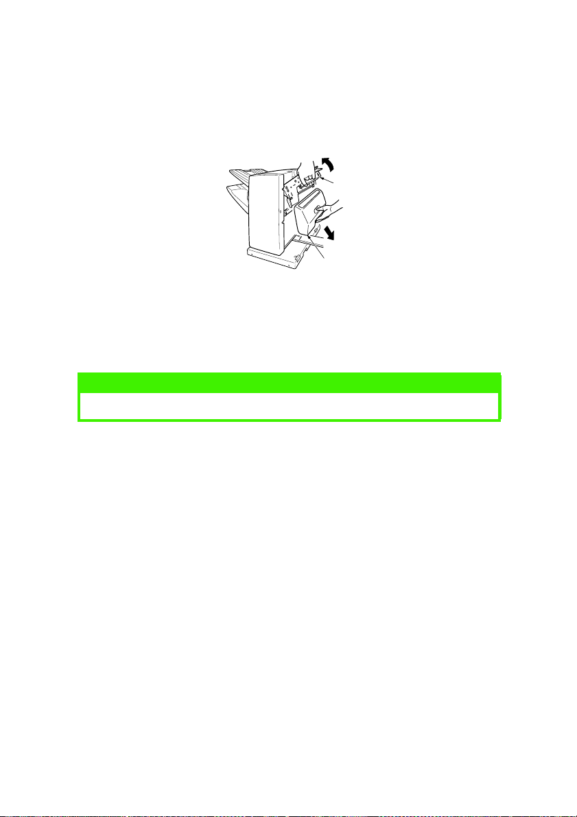
REMOVING JAMMED STAPLES
When stapling is not taking place as expected and there are still
staples in the staple cartridge unit, check for a staple jam.
Detach the Finisher.
1.
WARNING!
Do not touch the Finisher Guide (2) as it may be hot.
Rotate the Decurler Lever (1) to
(a)
point downwards.
Rotate the Release Lever (3)
(b)
upwards and detach the
Finisher from the printer.
Open the Staple Cover (1) to
(c)
expose the Staple Unit (2).
2
1
3
1
2
48 < TROUBLESHOOTING
Page 49

Remove the staple cartridge unit from the staple unit.
2.
WARNING!
Be careful to avoid components and edges inside the Finisher.
Do not touch the Staple Unit motor (3) which may be hot.
Lift the blue Lock Lever (1) and
(a)
rotate the Staple Unit (2) in the
direction of the arrow.
3
Holding the Staple Unit (3) as
(b)
shown, raise the light blue Knob
(1) and remove the Staple
Cartridge unit (2).
2
English
1
1
2
3
TROUBLESHOOTING > 49
Page 50

Remove the jammed staples.
3.
Use the handle (2) to open the
(a)
1
cartridge unit.
Remove and discard the jammed
(b)
staples (1).
Use handle (2) to close the
(c)
cartridge unit.
Fit the Staple Cartridge unit into the
4.
Staple Unit.
WARNING!
Be careful to avoid components and edges inside the Finisher.
Push the Staple Cartridge unit (1)
(a)
into the Staple Unit (2) until a
click is heard.
Rotate the Staple Unit (2) in the
(b)
direction of the arrow.
2
1
50 < TROUBLESHOOTING
2
Page 51

Attach the Finisher to the printer.
5.
Close the Staple Cover (2).
(a)
Push the Finisher towards the printer until it clicks into
(b)
position.
Return the Decurler Lever (3) to the horizontal position.
(c)
English
1
2
3
NOTE
If the Decurler Lever is not returned to the horizontal position, it may
cause the paper to jam.
TROUBLESHOOTING > 51
Page 52

MAINTAINING THE FINISHER
For a full list of error and warning messages, refer to “Appendix C Error and warning messages”.
The two tasks involved in maintaining the Finisher are:
l replenishing the staple cartridge unit when the staples are
(almost) exhausted
(See “Appendix D - Consumables” for details of ordering new
staples.)
l disposing of the punch chips (i.e. small circular punchings)
that accumulate in the punch Chip Box
52 < MAINTAINING THE FINISHER
Page 53

REPLENISHING THE STAPLE CARTRIDGE UNIT
NOTE
Your Finisher is supplied with a cartridge of staples pre-installed.
When the staple supply is almost exhausted, the following message
appears at the printer control panel:
NO STAPLE
Continue as follows:
Detach the Finisher.
1.
WARNING!
Do not touch the Finisher Guide (2) as it may be hot.
Rotate the Decurler Lever (1)
(a)
to point downwards.
Rotate the Release Lever (3)
(b)
upwards and detach the
Finisher from the printer.
2
1
English
Open the Staple Cover (1) to
(c)
expose the Staple Unit (2).
MAINTAINING THE FINISHER > 53
3
1
2
Page 54

Remove the Staple Cartridge unit from the Staple Unit.
2.
WARNING!
Be careful to avoid components and edges inside the Finisher.
Do not touch the Staple Unit motor (3) which may be hot.
Lift the blue Lock Lever (1) and
(a)
rotate the Staple Unit (2) in the
direction of the arrow.
3
2
Holding the Staple Unit (3) as
(b)
shown, raise the light blue
Knob (1) and remove the Staple
Cartridge unit (2).
1
1
2
3
54 < MAINTAINING THE FINISHER
Page 55

Fit the new staples.
3.
(a)
(b)
(c)
(d)
Remove the empty staple
cartridge from the Staple
Cartridge unit.
Remove the new cartridge of
staples from its packaging, but
do not yet remove the Tape (1).
Push the new cartridge of
staples into the Staple
Cartridge unit until a click is
heard.
Remove the Tape (1).
English
1
1
MAINTAINING THE FINISHER > 55
Page 56

Fit the Staple Cartridge unit into the Staple Unit.
4.
WARNING!
Be careful to avoid components and edges inside the Finisher.
Push the Staple Cartridge unit
(a)
(1) into the Staple Unit (2) until
a click is heard.
Rotate the Staple Unit (2) in
(b)
the direction of the arrow.
2
1
56 < MAINTAINING THE FINISHER
Page 57

Attach the Finisher to the printer.
5.
Close the Staple Cover (2).
(a)
Push the Finisher towards the printer until it clicks into
(b)
position.
Return the Decurler Lever (3) to the horizontal position.
(c)
English
1
2
3
NOTES
> If the Decurler Lever (3) is not returned to the horizontal position, it
may cause the paper to jam.
> If the Stapler Cartridge has not been properly fitted, the following
error message will occur at the printer control panel:
CHECK STAPLER CARTRIDGE
471: STAPLER CARTRIDGE MISSING
MAINTAINING THE FINISHER > 57
Page 58

REMOVING THE PUNCH CHIPS
When the punch Chip Box is almost full and requires to be emptied,
the following message appears at the printer control panel:
PUNCH CHIP OVERFLOW
Continue as follows:
Detach the Finisher.
1.
WARNING!
If the Finisher Guide (2) is hot, give it time to cool before proceeding.
Rotate the Decurler Lever (1)
(a)
to point downwards.
Rotate the Release Lever (3)
(b)
upwards and detach the
Finisher from the printer.
2
1
3
58 < MAINTAINING THE FINISHER
Page 59
English
Remove the punch Chip Box.
2.
Rotate the Finisher Guide (1) upwards and hold it in the
(a)
raised position while you carefully remove the Chip Box
(2).
1
2
Lower the Finisher Guide (1) back into position.
(b)
NOTE
Be careful not to spill the punch chips by tilting the Chip Box too much.
Dispose of the punch chips.
(c)
Refit the punch Chip Box.
3.
Rotate the Finisher Guide (1) upwards and hold it in the
(a)
raised position while you refit the Chip Box (2).
Lower the Finisher Guide (1) back into position.
(b)
MAINTAINING THE FINISHER > 59
Page 60

Attach the Finisher to the printer.
4.
Push the Finisher towards the printer until it clicks into
(a)
position.
1
Return the Decurler Lever (1) to the horizontal position.
(b)
NOTES
> If the Decurler Lever is not returned to the horizontal position, it may
cause the paper to jam.
> If the punch Chip Box has not been properly fitted, the following
error message will occur at the printer control panel:
CHECK PUNCH CHIP BOX
472: PUNCH CHIP BOX MISSING
60 < MAINTAINING THE FINISHER
Page 61

APPENDIX A - SPECIFICATION
MAIN CHARACTERISTICS
The main characteristics of the Finisher are specified in the following
table:
English
HARACTERISTIC
C
Overall function Mass stacking, stapling, punching, job offsetting
Stacking capacity
Paper size Face up stacker: A3, A4, A5, A6, B4, B5, Letter, Tabloid, Legal
Paper weight
Stapling paper size A4 (landscape), Letter (landscape)
Staple paper capacity Maximum 30 sheets or paper thickness 3mm (weight 64 to
Punch holes Either 2-hole or 4-hole punching
Punching paper size Long-side binding: A4 (landscape), Letter (landscape), B5
Punching paper weight
Power supply 100 - 240V +/- 10%, 50-60 +/- 3Hz AC
Power consumption During operation: 62W maximum, 30W average
Operating environment During operation: 10 to 32 deg C, 20 to 80%RH (max.wet
Normal usage Average power ON time: 220 hr/month
Consumabl es Staples
Weight Approximately 25kg
Face up stacker: about 100 sheets at 80g/m
Face down stacker: about 1000 sheets at 80g/m2 (with
stacker full detection)
(13in, 13.5in, 14in), Executive, Custom (width: 100 to
297mm, length: 149 to 1200mm)
Face down stacker: A4 (landscape), Letter (landscape)
Face up stacker: weight 64 to 200g/m2 (only paper up to
2
104g/m
Face down stacker: weight 64 to 104g/m
104g/m
(landscape)
Short side binding: A3, A4 (portrait), A5, A6, B4, B5 (portrait),
Letter (portrait), Tabloid, Legal (13in, 13.5in, 14in),
Executive, Custom (width: 100 to 297mm, length: 149 to
1200mm)
64 to 104g/m
Idling: 5W maximum
bulb temp. 25 deg C, max. wet bulb temp. difference 2 deg C)
Not in operation: 0 to 43 deg C, 10 to 90% RH (max.wet bulb
temp. 26.8 deg C, max. wet bulb temp. difference 2 deg C)
Average print quantity: 7000 sheets/month
can be punched)
2
)
2
PECIFICATION
S
2
2
APPENDIX A - SPECIFICATION > 61
Page 62

HARACTERISTIC
C
PECIFICATION
S
Compatible printers C9300/C9500 printers
Printer tray configuration Second tray + high capacity feed tray unit
See the following configuration diagram.
Dimensions See the following configuration diagram.
(Cabinet width = 560mm)
CONFIGURATION DIAGRAM
859mm
629mm
316mm
539mm
490mm
666mm
62 < APPENDIX A - SPECIFICATION
Page 63

English
APPENDIX B - PAPER FEED AND EJECTION DETAILS
PRINTER PAPER FEED DETAILS
MP: Multi-purpose tray
s: used for single-sided printing only
d: used for both single-sided and double-sided (optional) printing
x: cannot be used
IZE AND WEIGHT
S
Normal paper, 64 to 80g/m
Normal paper, 64 to 80g/m
Normal paper, 64 to 80g/mNormal paper, 64 to 80g/m
A4 (landscape), Letter (landscape) s s s
A4 (portrait), Letter (portrait) s s s
B5 (landscape) s s s
A5, B5 (portrait), B4, Legal (13in,
13.5in, 14in), Executive, tabloid
A3 s s s
A3 outsize, A3 wide (SRA3),
Tablo id extra
A6 x x s
Custom - Note 2 x x s
Normal paper, 81 to 104g/m
Normal paper, 81 to 104g/m
Normal paper, 81 to 104g/mNormal paper, 81 to 104g/m
A4 (landscape), Letter (landscape) d d s
A4 (portrait), Letter (portrait) d d s
B5 (landscape) d d s
A5, B5 (portrait), B4, Legal (13in,
13.5in, 14in), Executive, Tabloid
A3 d d s
A3 wide (SRA3), Tabloid extra d d s
A3 outsize s s s
A6 s x s
Custom - Note 2 x x s
Normal paper, 105 to 175g/m
Normal paper, 105 to 175g/m
Normal paper, 105 to 175g/mNormal paper, 105 to 175g/m
A4 (landscape), Letter (landscape) s s s
A4 (portrait), Letter (portrait) s s s
2222
2222
2222
RAY
T
1 T
sss
sss
d d s
RAYS
N
2 TO 5
OTE
1
ANUAL FEED
M
MP
APPENDIX B - PAPER FEED AND EJECTION DETAILS > 63
Page 64

IZE AND WEIGHT
S
A5, B5, B4, Legal (13in, 13.5in,
14in), Executive, Tabloid
A3 s s s
A3 wide (SRA3), Tabloid extra s s s
A3 outsize s s s
A6 s x s
Custom - Note 2 x x s
Normal paper, 176 to 198g/m
Normal paper, 176 to 198g/m
Normal paper, 176 to 198g/mNormal paper, 176 to 198g/m
A4 (landscape), Letter (landscape) x x s
A4 (portrait), Letter (portrait) x x s
A5, B5, B4, Legal (13in, 13.5in,
14in), Executive, Tabloid
A3 x x s
A3 outsize, A3 wide (SRA3),
Tabloid extra - Note 3
A6 x x s
Custom - Note 2 x x s
Post card
Post card
Post cardPost card
Post card, Double post card s x s
Envelope
Envelope
EnvelopeEnvelope
Envelope 1 (portrait No 3) - Note 4 x x x
Envelope 2 (portrait No 4) - Note 4 x x x
Envelope 3 (portrait No 4) - Note 4 x x x
Com-9, Com-10, DL, C4, Monarch
- Note 4
Envelope 4 (A4 size), C5 x x s
Label stationery
Label stationery
Label stationeryLabel stationery
A4, Letter x x s
OHP sheet
OHP sheet
OHP sheetOHP sheet
A4, Letter s x s
2222
RAY
T
1 T
sxs
x x s
x x x
xxx
RAYS
N
2 TO 5
OTE
1
ANUAL FEED
M
MP
Notes:
Trays (5 in total) are numbered from the top down.
1.
When feeding the Finisher, printer Custom dimensions are
2.
width 100 to 297mm and length 149 to 1200mm.
When feeding the Finisher, A3 outsize, A3 wide (SRA3) and
3.
²
Tabloid extra of weight 176 to 198g/m
64 < APPENDIX B - PAPER FEED AND EJECTION DETAILS
cannot be used.
Page 65

When feeding the Finisher, Envelope 1(portrait No 3), Envelope
4.
2 (portrait No 4), Envelope 3 (landscape No 4), Com-9, Com-10,
DL, C4 and Monarch cannot be used.
PAPER EJECTION DETAILS
FINISHER FACE UP STACKER
(No stapling possible)
EO: ejection only
PL: punched for long-side binding
PS: punched for short-side binding
s: used for single-sided printing only
d: used for both single-sided and (optional) double-sided printing
x: cannot be used
IZE AND WEIGHT
S
Normal paper, 64 to 80g/m
Normal paper, 64 to 80g/m
Normal paper, 64 to 80g/mNormal paper, 64 to 80g/m
A4 (landscape), Letter (landscape) s s x
A4 (portrait), Letter (portrait) s x s
B5 (landscape) s s x
A5, B5 (portrait), B4, Legal (13in,
13.5in, 14in), Executive, Tabloid
A3 s x s
A3 outsize, A3 wide (SRA3),
Tablo id extra
A6 s x s
Custom s x s
Normal paper, 81 to 104g/m
Normal paper, 81 to 104g/m
Normal paper, 81 to 104g/mNormal paper, 81 to 104g/m
A4 (landscape), Letter (landscape) d d x
A4 (portrait), Letter (portrait) d x d
B5 (landscape) d d x
A5, B5 (portrait), B4, Legal (13in,
13.5in, 14in), Executive, Tabloid
A3 d x d
A3 wide (SRA3), Tabloid extra x x x
A3 outsize x x x
2222
2222
EO PL PS
sxs
xxx
d x d
English
APPENDIX B - PAPER FEED AND EJECTION DETAILS > 65
Page 66

IZE AND WEIGHT
S
A6 s x s
Custom s x s
Normal paper, 105 to 175g/m
Normal paper, 105 to 175g/m
Normal paper, 105 to 175g/mNormal paper, 105 to 175g/m
A4 (landscape), Letter (landscape) s - Note 1 x x
A4 (portrait), Letter (portrait) s - Note 1 x x
A5, B5, B4, Legal (13in, 13.5in,
14in), Executive, Tabloid
A3 s - Note 1 x x
A3 wide (SRA3), Tabloid extra x x x
A3 outsize x x x
A6 s x x
Custom s x x
Normal paper, 176 to 198g/m
Normal paper, 176 to 198g/m
Normal paper, 176 to 198g/mNormal paper, 176 to 198g/m
A4 (landscape), Letter (landscape) s x x
A4 (portrait), Letter (portrait) s x x
A5, B5, B4, Legal (13in, 13.5in,
14in), Executive, Tabloid
A3 s x x
A3 outsize, A3 wide (SRA3),
Tablo id extra
A6 s x x
Custom s x x
Post card
Post card
Post cardPost card
Post card, Double post card s x x
Envelope
Envelope
EnvelopeEnvelope
Envelope 1 (portrait No 3) x x x
Envelope 2 (portrait No 4) x x x
Envelope 3 (portrait No 4) x x x
Com-9, Com-10, DL, C4, Monarch x x x
Envelope 4 (A4 size), C5 s x x
Label stationery
Label stationery
Label stationeryLabel stationery
A4, Letter s x x
OHP sheet
OHP sheet
OHP sheetOHP sheet
A4, Letter s x x
2222
2222
EO PL PS
s - Note 1 x x
s x x
x x x
Notes:
1.
105g/m
printing.
2
(maximum) paper can be used for double-sided
66 < APPENDIX B - PAPER FEED AND EJECTION DETAILS
Page 67

FINISHER FACE DOWN STACKER
The only possible paper usage is as follows:
EO: ejection only
PL: punched for long-side binding
PS: punched for short-side binding
ST: stapling
s: used for single-sided printing only
d: used for both single-sided and double-sided printing
x: cannot be used
IZE AND WEIGHT
S
Normal paper, 64 to 80g/m
Normal paper, 64 to 80g/m
Normal paper, 64 to 80g/mNormal paper, 64 to 80g/m
A4 (landscape), Letter (landscape) s s x s
Normal paper, 81 to 104g/m
Normal paper, 81 to 104g/m
Normal paper, 81 to 104g/mNormal paper, 81 to 104g/m
A4 (landscape), Letter (landscape) d d x d
2222
2222
EO PL PS ST
English
APPENDIX B - PAPER FEED AND EJECTION DETAILS > 67
Page 68

PRINTER FACE DOWN STACKER
EO: ejection only (no punching or stapling)
s: used for single-sided printing only
d: used for both single-sided and double-sided printing
x: cannot be used
IZE AND WEIGHT
S
Normal paper, 64 to 80g/m
Normal paper, 64 to 80g/m
Normal paper, 64 to 80g/mNormal paper, 64 to 80g/m
A4 (landscape), Letter (landscape) s
A4 (portrait), Letter (portrait) s
B5 (landscape) s
A5, B5 (portrait), B4, Legal (13in, 13.5in, 14in),
Executive, Tabloid
A3 s
A3 outsize, A3 wide (SRA3), Tabloid extra s
A6 x
Custom x
Normal paper, 81 to 104g/m
Normal paper, 81 to 104g/m
Normal paper, 81 to 104g/mNormal paper, 81 to 104g/m
A4 (landscape), Letter (landscape) d
A4 (portrait), Letter (portrait) d
B5 (landscape) d
A5, B5 (portrait), B4, Legal (13in, 13.5in, 14in),
Executive, Tabloid
A3 d
A3 wide (SRA3), Tabloid extra d
A3 outsize s
A6 x
Custom x
Normal paper, 105 to 175g/m
Normal paper, 105 to 175g/m
Normal paper, 105 to 175g/mNormal paper, 105 to 175g/m
A4 (landscape), Letter (landscape) s - Note 1
A4 (portrait), Letter (portrait) s - Note 1
A5, B5, B4, Legal (13in, 13.5in, 14in), Executive, Tabloid s - Note 1
A3 s - Note 1
A3 wide (SRA3), Tabloid extra s - Note 1
A3 outsize s
A6 x
Custom x
2222
2222
2222
EO
s
d
68 < APPENDIX B - PAPER FEED AND EJECTION DETAILS
Page 69

IZE AND WEIGHT
S
Normal paper, 176 to 198g/m
Normal paper, 176 to 198g/m
Normal paper, 176 to 198g/mNormal paper, 176 to 198g/m
A4 (landscape), Letter (landscape) x
A4 (portrait), Letter (portrait) x
A5, B5, B4, Legal (13in, 13.5in, 14in), Executive, Tabloid x
A3 x
A3 outsize, A3 wide (SRA3), Tabloid extra x
A6 x
Custom x
Post card
Post card
Post cardPost card
Post card, Double post card x
Envelope
Envelope
EnvelopeEnvelope
Envelope 1 (portrait No 3) x
Envelope 2 (portrait No 4) x
Envelope 3 (portrait No 4) x
Com-9, Com-10, DL, C4, Monarch x
Envelope 4 (A4 size), C5 x
Label stationery
Label stationery
Label stationeryLabel stationery
A4, Letter x
OHP sheet
OHP sheet
OHP sheetOHP sheet
A4, Letter x
2222
English
EO
Notes:
1.
105g/m2 (maximum) paper can be used for double-sided
printing.
APPENDIX B - PAPER FEED AND EJECTION DETAILS > 69
Page 70

APPENDIX C - ERROR AND WARNING MESSAGES
The following table summarises the error and warning messages that
can appear on the printer control panel when a Finisher is being used.
Each message is accompanied by the “Attention” LED flashing and
printing being stopped. Suggested remedial actions are given with
the messages below.
RROR/WARNING MESSAGESMEANING
E
NO STAPLE There are almost no staples
left.
PUNCH CHIP OVERFLOW The punch chip box is
COULD NOT STAPLE. TOO MUCH
PAP ER
REMOVE THE PAPER
482: FINISHER STACKER FULL
REMOVE FINISHER
nnn: PAPER JAM
CHECK STAPLE CARTRIDGE
471: STAPLE CARTRIDGE
MISSING
CHECK PUNCH CHIP BOX
472: PUNCH CHIP BOX MISSING
INSTALL FINISHER
473: FINISHER REMOVED
SERVICE CALL
nnn: FATAL ERROR
almost full and requires to
be emptied.
The number of stapled sets
exceeds a pre-determined
value.
The face down stacker is full. Remove all paper from the
Paper has jammed inside
the Finisher.
The staple cartridge is not
fitted properly or is missing.
The punch chip box is not
fitted properly or is missing.
The Finisher is not attached
correctly to the printer.
A serious error has occurred
and you should not attempt
to use the Finisher further
until the error has been
rectified.
EMEDIAL ACTION
R
See “Replenishing the
staple cartridge unit”
See “Removing the punch
chips”.
Remove all stapled copies
from the Finisher.
face down stacker.
See “Clearing a paper
jam”
(nnn values 361 to 367)
See “Replenishing the
staple cartridge unit”
See “Removing the punch
chips”
Check Finisher is attached
to printer.
Contact your Oki Service
Centre and quote the nnn
value (090 to 094 or 186).
70 < APPENDIX C - ERROR AND WARNING MESSAGES
Page 71

APPENDIX D - CONSUMABLES
NOTE
Use only genuine Oki consumables from your Oki dealer to avoid
possible damage to the Finisher.
STAPLES
English
RODUCT NAME
P
Box of Staples
(Finisher)
ESCRIPTION
D
Special staples for Finisher use.
(One box contains 3 cartridges, each
containing 3000 staples).
RDER CODE
O
01078301
APPENDIX D - CONSUMABLES > 71
Page 72

72 < APPENDIX D - CONSUMABLES
Page 73

OKI CONTACT DETAILS
English
Oki Systems (UK) Limited
550 Dundee Road
Slough Trading Estate
Slough, SL1 4LE
Tel: +44 (0) 1753 819819
Fax: +44 (0) 1753 819899
http://www.oki.co.uk
Oki Systems Ireland Limited
The Square Industrial Complex
Tallaght, Dublin 24
Ireland
Tel: +353 1 4049590
Fax: +353 1 4049591
http://www.oki.ie
OKI Systems (Ireland) Ltd
40 Sydenham Park
Belfast, BT4 1PW
Tel: +44 (0) 28 90 20 1110
http://www.oki.ie
Technical Support for all Ireland
Tel : +353 1 4049570
Fax: +353 1 4049555
E-mail: tech.support@oki.ie
Oki Systèmes (France) S.A.
44-50 Av. du Général de Gaulle
94240 L'Hay les Roses
Téléphone: 01 46 15 80 00
Télécopie: 01 46 15 80 60
http://www.oki.fr
OKI Systems (Italia) S.p.A.
c.c. “Il Girasole” - Lotto 3.05/B
20084 Lacchiarella (MI)
Tel. 02900261
Fax: 029007549
http://www.oki.it
Oki Systems (Deutschland) GmbH
Hansaallee 187
40549 Düsseldorf
Tel: +49 (0) 211 52 66-0
Fax: +49 (0) 211 59 33-45
BBS: +49 (0) 211 5266-222
(300-33600 bps, 8, N, 1)
http://www.oki.de
Oki Systems (Iberica),
S.A.C/Teide, 3-28700
(San Sebastian de los Reyes)
Madrid
Tel: 91-3431620
Fax: 91-3431624
http://www.oki.es
Oki Systems (Ibérica) SA
Sucursal em Portugal
Rua Quinta do Paizinho
Edificio Bepor-Bloco 2-1 Dto.
2795-651 Carnaxide
Tel: 21 424 67 40
Fax: 21 417 29 12
http://www.oki.pt
Oki Service (Portugal)
Serviço de apoio técnico ao cliente
Tel: 808 200 197
OKI CONTACT DETAILS > 73
Page 74

Oki Systems (Österreich)
IZ-NÖ-Süd, Str. 2/M7/1
A-2355 Wiener Neudorf
Österreich
Tel: +43 (0)223/677110
Fax: +43 (0)223/67711018
http:// www.oki.at
Oki Systems (Schweiz)
Zurlindenstrasse 29
CH-4133 Pratteln bei Basel
Schweiz
Tel: +41 (0)61/8279494
Fax: +41 (0)61/8279490
http: //www.oki.ch
OKI Systems (Norway) A/S
Hvamsvingen 9, P.O.Box 174
N-2013 Skjetten
Telefon: 63 89 36 00
Telefax: 63 89 36 01
Ordrefax: 63 89 36 02
http://www.oki.no
OKI Systems (Finland) Oy
Kutomotie 18 B, 5. krs,
00380 Helsinki
Puh. (09) 5404 420.
Int. +358 9 5404 420
Fax. (09) 5404 4223
Int. +358 9 5404 4223
Oki Systems (Danmark) a·s
Park Allé 382
2625 Vallensbæk
Tlf: 43 66 65 30
Fax: 43 66 65 90
http://www.oki.dk
OKI Systems (Sweden) AB
BOX 216
161 26 BROMMA
Telefonsupport: 0726-101 20
Vardagar: 09.00 - 11.30, 13.00 - 16.00
http://www.oki.se
74 < OKI CONTACT DETAILS
Page 75

INDEX
English
B
binding
long side...............................13
short side .............................13
C
component parts...........................9
Consumables..............................71
D
Decurler Lever.............................40
driver
Macintosh.............................33
Windows 2000 ......................25
Windows 95/98 ....................21
Windows NT4.0 .....................29
H
Hole positions ............................ 14
J
Job offset information .................17
M
maintenance...............................52
messages
error .....................................70
warning ................................70
P
paper
curl.......................................39
ejection.................................63
feed......................................63
jam .......................................41
Punch
information ...........................13
punch chips
removing ..............................58
S
Specification ..............................61
stacker
face down .............................12
face up..................................12
staple
cartridge ...............................49
jam .......................................48
position ................................16
replenishing..........................52
stapling details...........................15
T
troubleshooting
paper curl .............................39
paper jams............................41
staple jams ...........................48
INDEX > 75
Page 76

 Loading...