

Page 1
C332dn/C332dnw
User’s Guide
Page 2

P
REFACE
Every effort has been made to ensure that the information in this document is complete,
accurate, and up-to-date. The manufacturer assumes no responsibility for the results of
errors beyond its control. The manufacturer also cannot guarantee that changes in software
and equipment made by other manufacturers and referred to in this guide will not affect
the applicability of the information in it. Mention of software products manufactured by
other companies does not necessarily constitute endorsement by the manufacturer.
While all reasonable efforts have been made to
make this document as accurate and helpful
as possible, we make no warranty of any kind, expressed or implied, as to the accuracy or
completeness of the information contained herein.
The most up-to-date drivers and manuals are available from:
http://www.oki.com/printing/
Copyright © 2016. All rights reserved.
OKI is a registered trademark of Oki El
ectric Industry Co., Ltd.
Energy Star is a trademark of the United States Environmental Protection Agency.
Microsoft, MS-DOS and Windows are registered trademarks of Microsoft Corporation.
Apple, Macintosh, Mac and Mac OS are registered trademarks of Apple Inc.
Other product names and brand names are registered trademarks or trademarks of their
proprietors.
As an Energy Star Program Participant, the manufacturer has determined that
this product meets the Energy Star guidelines for energy efficiency.
This product complies with the requirements of the Council Directives 2014/30/
EU(EMC), 2014/35/EU(LVD),1999/5/EC (R&TTE), 2009/125/EC (ErP) and
2011/65/EU(RoHS), as amended where applicable, on the approximation of the
laws of the member states relating to Electromagnetic Compatibility, Low
Voltage, Radio & Telecommunications Terminal Equipment, Energy related
Products and Restriction on the use of certain Hazardous Substances in
electrical and electronic equipment.
The following cables were used to evaluate t
his product to achieve EMC directive
2014/30/EU compliance and configurations other than this may affect that compliance.
CABLE TYPE LENGTH
(METRE)
Power 1.8
USB 5.0
LAN 7.0
Preface > 2
CORE SHIELD
Page 3

E
w
w
w
.
o
k
i
.
c
o
m
/
p
r
i
n
t
i
n
g
/
MERGENCY FIRST AID
Take care with toner powder:
If swallowed, give small amounts of cold water and seek medical
attention. DO NOT attempt to induce vomiting.
If inhaled, move the person to an open area for fresh air. Seek medical
attention.
If it gets into the eyes, flush with large amounts of water for at least 15
minutes keeping eyelids open. Seek medical attention.
Spillages should be treated with cold water and soap to help reduce risk
of staining skin or clothing.
M
ANUFACTURER
Oki Data Corporation,
4-11-22 Shibaura, Minato-ku,
Tokyo 108-8551,
Japan
I
MPORTER TO THE
Oki Europe Limited
Blays House
Wick Road
Egham
Surrey, TW20 0HJ
United Kingdom
EU/
AUTHORISED REPRESENTATIVE
For all sales, support and general enquiries contact your local distributor.
E
NVIRONMENTAL
INFORMATION
Emergency first aid > 3
Page 4

C
ONTENTS
Preface . . . . . . . . . . . . . . . . . . . . . . . . . . . . . . . . . . . . . . . . . . . . . . . . . . .2
Emergency first aid . . . . . . . . . . . . . . . . . . . . . . . . . . . . . . . . . . . . . . . . . .3
Manufacturer. . . . . . . . . . . . . . . . . . . . . . . . . . . . . . . . . . . . . . . . . . . . . . .3
Importer to the EU/authorised representative. . . . . . . . . . . . . . . . . . . . .3
Environmental information . . . . . . . . . . . . . . . . . . . . . . . . . . . . . . . . . . . .3
Contents . . . . . . . . . . . . . . . . . . . . . . . . . . . . . . . . . . . . . . . . . . . . . . . . . .4
Notes, cautions and warnings . . . . . . . . . . . . . . . . . . . . . . . . . . . . . . . . . .6
About this guide . . . . . . . . . . . . . . . . . . . . . . . . . . . . . . . . . . . . . . . . . . . .7
Documentation suite . . . . . . . . . . . . . . . . . . . . . . . . . . . . . . . . . . . . . . . 7
On-line usage . . . . . . . . . . . . . . . . . . . . . . . . . . . . . . . . . . . . . . . . . . . . 8
Printing pages. . . . . . . . . . . . . . . . . . . . . . . . . . . . . . . . . . . . . . . . . . . . 8
Getting Started . . . . . . . . . . . . . . . . . . . . . . . . . . . . . . . . . . . . . . . . . . . . .9
Overview . . . . . . . . . . . . . . . . . . . . . . . . . . . . . . . . . . . . . . . . . . . . . . . 9
Front view . . . . . . . . . . . . . . . . . . . . . . . . . . . . . . . . . . . . . . . . . . . . 9
Rear view . . . . . . . . . . . . . . . . . . . . . . . . . . . . . . . . . . . . . . . . . . . . .10
Changing the display language . . . . . . . . . . . . . . . . . . . . . . . . . . . . . . . .10
Switching on. . . . . . . . . . . . . . . . . . . . . . . . . . . . . . . . . . . . . . . . . . .10
Switching off. . . . . . . . . . . . . . . . . . . . . . . . . . . . . . . . . . . . . . . . . . .10
Wireless module . . . . . . . . . . . . . . . . . . . . . . . . . . . . . . . . . . . . . . . .10
Energy saving settings. . . . . . . . . . . . . . . . . . . . . . . . . . . . . . . . . . . . . .11
Power saving mode . . . . . . . . . . . . . . . . . . . . . . . . . . . . . . . . . . . . . .11
Sleep mode . . . . . . . . . . . . . . . . . . . . . . . . . . . . . . . . . . . . . . . . . . .11
Returning to standby mode . . . . . . . . . . . . . . . . . . . . . . . . . . . . . . . .11
Paper recommendations . . . . . . . . . . . . . . . . . . . . . . . . . . . . . . . . . . . . .12
Cassette trays. . . . . . . . . . . . . . . . . . . . . . . . . . . . . . . . . . . . . . . . . . . .13
Multi purpose tray . . . . . . . . . . . . . . . . . . . . . . . . . . . . . . . . . . . . . . . . .14
Output tray (face down). . . . . . . . . . . . . . . . . . . . . . . . . . . . . . . . . . . . .14
Rear output tray (face up) . . . . . . . . . . . . . . . . . . . . . . . . . . . . . . . . . . .14
Duplex . . . . . . . . . . . . . . . . . . . . . . . . . . . . . . . . . . . . . . . . . . . . . . . . .14
Loading paper . . . . . . . . . . . . . . . . . . . . . . . . . . . . . . . . . . . . . . . . . . . . .15
Cassette trays. . . . . . . . . . . . . . . . . . . . . . . . . . . . . . . . . . . . . . . . . . . .15
Multi purpose tray . . . . . . . . . . . . . . . . . . . . . . . . . . . . . . . . . . . . . . . . .18
Operation . . . . . . . . . . . . . . . . . . . . . . . . . . . . . . . . . . . . . . . . . . . . . . . .19
Menu functions . . . . . . . . . . . . . . . . . . . . . . . . . . . . . . . . . . . . . . . . . . . .20
Operator panel . . . . . . . . . . . . . . . . . . . . . . . . . . . . . . . . . . . . . . . . . . . .20
How to change the settings - user . . . . . . . . . . . . . . . . . . . . . . . . . . . . . .22
How to change the settings - administrator . . . . . . . . . . . . . . . . . . . . . . .22
Menus . . . . . . . . . . . . . . . . . . . . . . . . . . . . . . . . . . . . . . . . . . . . . . . . .23
Configuration . . . . . . . . . . . . . . . . . . . . . . . . . . . . . . . . . . . . . . . . . .23
Print Info . . . . . . . . . . . . . . . . . . . . . . . . . . . . . . . . . . . . . . . . . . . . .25
Menus . . . . . . . . . . . . . . . . . . . . . . . . . . . . . . . . . . . . . . . . . . . . . . .26
Admin Setup. . . . . . . . . . . . . . . . . . . . . . . . . . . . . . . . . . . . . . . . . . .35
Network Setup . . . . . . . . . . . . . . . . . . . . . . . . . . . . . . . . . . . . . . . . .36
USB Setup . . . . . . . . . . . . . . . . . . . . . . . . . . . . . . . . . . . . . . . . . . . .37
Print Setup . . . . . . . . . . . . . . . . . . . . . . . . . . . . . . . . . . . . . . . . . . . .37
Color Menu . . . . . . . . . . . . . . . . . . . . . . . . . . . . . . . . . . . . . . . . . . . .40
PS Setup . . . . . . . . . . . . . . . . . . . . . . . . . . . . . . . . . . . . . . . . . . . . .41
PCL Setup . . . . . . . . . . . . . . . . . . . . . . . . . . . . . . . . . . . . . . . . . . . .42
XPS Setup . . . . . . . . . . . . . . . . . . . . . . . . . . . . . . . . . . . . . . . . . . . .43
IBM PPR Setup . . . . . . . . . . . . . . . . . . . . . . . . . . . . . . . . . . . . . . . . .44
EPSON FX Setup . . . . . . . . . . . . . . . . . . . . . . . . . . . . . . . . . . . . . . . .45
Panel Setup . . . . . . . . . . . . . . . . . . . . . . . . . . . . . . . . . . . . . . . . . . .46
Contents > 4
Page 5

Power Setup . . . . . . . . . . . . . . . . . . . . . . . . . . . . . . . . . . . . . . . . . . .46
Tray Setup . . . . . . . . . . . . . . . . . . . . . . . . . . . . . . . . . . . . . . . . . . . .46
Others Setup . . . . . . . . . . . . . . . . . . . . . . . . . . . . . . . . . . . . . . . . . .47
Settings . . . . . . . . . . . . . . . . . . . . . . . . . . . . . . . . . . . . . . . . . . . . . .48
Change Password . . . . . . . . . . . . . . . . . . . . . . . . . . . . . . . . . . . . . . .48
Print statistics . . . . . . . . . . . . . . . . . . . . . . . . . . . . . . . . . . . . . . . . . .49
AirPrint . . . . . . . . . . . . . . . . . . . . . . . . . . . . . . . . . . . . . . . . . . . . . .49
Google Cloud Print. . . . . . . . . . . . . . . . . . . . . . . . . . . . . . . . . . . . . . .50
Wireless Setting . . . . . . . . . . . . . . . . . . . . . . . . . . . . . . . . . . . . . . . .51
Wireless (AP Mode) Setting . . . . . . . . . . . . . . . . . . . . . . . . . . . . . . . .52
Boot Menu . . . . . . . . . . . . . . . . . . . . . . . . . . . . . . . . . . . . . . . . . . . .52
Maintenance . . . . . . . . . . . . . . . . . . . . . . . . . . . . . . . . . . . . . . . . . . . . . .54
Replacing consumable items. . . . . . . . . . . . . . . . . . . . . . . . . . . . . . . . . .54
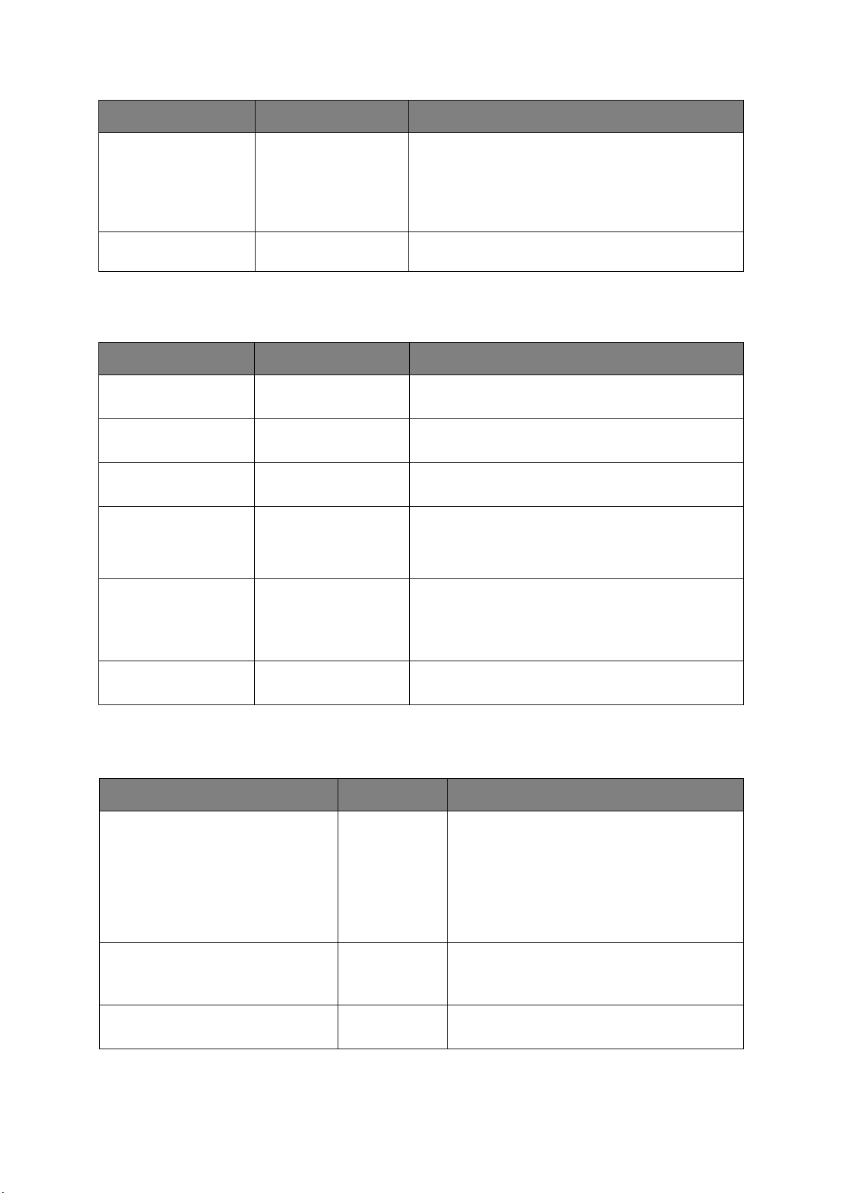
Toner cartridge replacement. . . . . . . . . . . . . . . . . . . . . . . . . . . . . . . .54
Replacing the transfer belt unit . . . . . . . . . . . . . . . . . . . . . . . . . . . . . .58
Fuser replacement. . . . . . . . . . . . . . . . . . . . . . . . . . . . . . . . . . . . . . .60
Cleaning. . . . . . . . . . . . . . . . . . . . . . . . . . . . . . . . . . . . . . . . . . . . . . . .62
...the unit casing . . . . . . . . . . . . . . . . . . . . . . . . . . . . . . . . . . . . . . . .62
...the LED head . . . . . . . . . . . . . . . . . . . . . . . . . . . . . . . . . . . . . . . . .62
Installing upgrades . . . . . . . . . . . . . . . . . . . . . . . . . . . . . . . . . . . . . . . . .63
Additional paper tray . . . . . . . . . . . . . . . . . . . . . . . . . . . . . . . . . . . . . . .63
Setting the driver device options. . . . . . . . . . . . . . . . . . . . . . . . . . . . .64
Wireless LAN Module . . . . . . . . . . . . . . . . . . . . . . . . . . . . . . . . . . . . . . .65
Precations when using wireless LAN. . . . . . . . . . . . . . . . . . . . . . . . . . .65
Connecting via wireless LAN (Infrastructure mode) . . . . . . . . . . . . . . . .66
Connecting via wireless LAN (AP mode) . . . . . . . . . . . . . . . . . . . . . . . .68
Troubleshooting . . . . . . . . . . . . . . . . . . . . . . . . . . . . . . . . . . . . . . . . . . .69
Major printer components and paper path . . . . . . . . . . . . . . . . . . . . . . . .69
Paper sensor error codes . . . . . . . . . . . . . . . . . . . . . . . . . . . . . . . . . . . .70
Clearing paper jams . . . . . . . . . . . . . . . . . . . . . . . . . . . . . . . . . . . . . . .71
Dealing with unsatisfactory printing. . . . . . . . . . . . . . . . . . . . . . . . . . . . .76
Before Machine Disposal . . . . . . . . . . . . . . . . . . . . . . . . . . . . . . . . . . . . .78
Specifications . . . . . . . . . . . . . . . . . . . . . . . . . . . . . . . . . . . . . . . . . . . . .79
Index . . . . . . . . . . . . . . . . . . . . . . . . . . . . . . . . . . . . . . . . . . . . . . . . . . . .80
Oki contact details. . . . . . . . . . . . . . . . . . . . . . . . . . . . . . . . . . . . . . . . . .81
Contents > 5
Page 6

N
OTES, CAUTIONS AND WARNINGS
NOTE
A note provides additional information to supplement the main text.
CAUTION!
A caution provides additional information which, if ignored, may
result in equipment malfunction or damage.
WARNING!
A warning provides additional information which, if ignored, may
result in a risk of personal injury.
For the protection of your product, and in order to ensure that you benefit from its full
functionality, this model has been designed to operate only with genuine original toner
cartridges. Any other toner cartridge may not operate at all, even if it is described as
“compatible”, and if it does work, your product's performance and print quality may be
degraded.
Use of non-genuine products may invalidate your warranty.
Specifications subject to change without notice. All trademarks acknow
ledged.
Notes, cautions and warnings > 6
Page 7

A
BOUT THIS GUIDE
NOTE
Images used in this manual may include optional features that your product
does not have installed.
D
OCUMENTATION SUITE
This guide is part of a suite of online and printed documentation provided to help you
become familiar with your product and to make the best use of its many powerful features.
The documentation is summarised below for reference and is found on the manuals DVD
unless indicated otherwise:
> Installation Safety booklet: prov
This is a paper document that is packaged with th
setting up your machine.
> Set-up guide: describes how
This is a paper document that is packaged with the product.
> User’s Guide: help
of its many features. Also included are guidelines for troubleshooting and
maintenance to ensure that it performs at its best. Additionally, information is
provided for adding optional accessories as your printing needs evolve.
> Network Guide: h
network interface card.
> Printing Guide: helps y
software supplied with your product.
> Barcode Printing Guide: helps
barcode printing feature.
> Installation Guides: accompany consumabl
describe how to install them.
These are paper documents that
accessories.
> On-line Help: on-lin
software.
s you become familiar with your product and make the best use
elps you become familiar with the functionality of the built in
ou become familiar with the many features of the driver
e information accessible from the printer driver and utility
ides information for safe use of your product.
e product and should be read before
to unpack, connect and turn on your product.
you become familiar with your product’s built in
e items and optional accessories to
are packaged with the consumables and optional
Depending on your OS, model or version, the d
different.
About this guide > 7
escription on this document may be
Page 8
ON-
1
2
3
LINE USAGE
This guide is intended to be read on screen using Adobe Reader. Use the navigation and
viewing tools provided in Adobe Reader.
There are many cross-references within t
his book, each highlighted as blue text. When you
click on a cross-reference the display will instantly jump to the part of the manual
containing the referenced material.
By using the button in Adobe Reader, you can navigat
e direct
ly back to where you were
before.
You can access specific information in two ways:
> In the list of bookmarks dow
n the left hand side of your screen, click on the topic of
interest to jump to the required topic. (If the bookmarks are not available, use the
“Contents” on page 4.)
> In the list of bookmarks, clic
k on Index to jump to the Index. (If the bookmarks are
not available, use the “Contents” on page 4.) Find the term of interest in the
alphabetically arranged index and click on the associated
page number to jump to
the page containing the term.
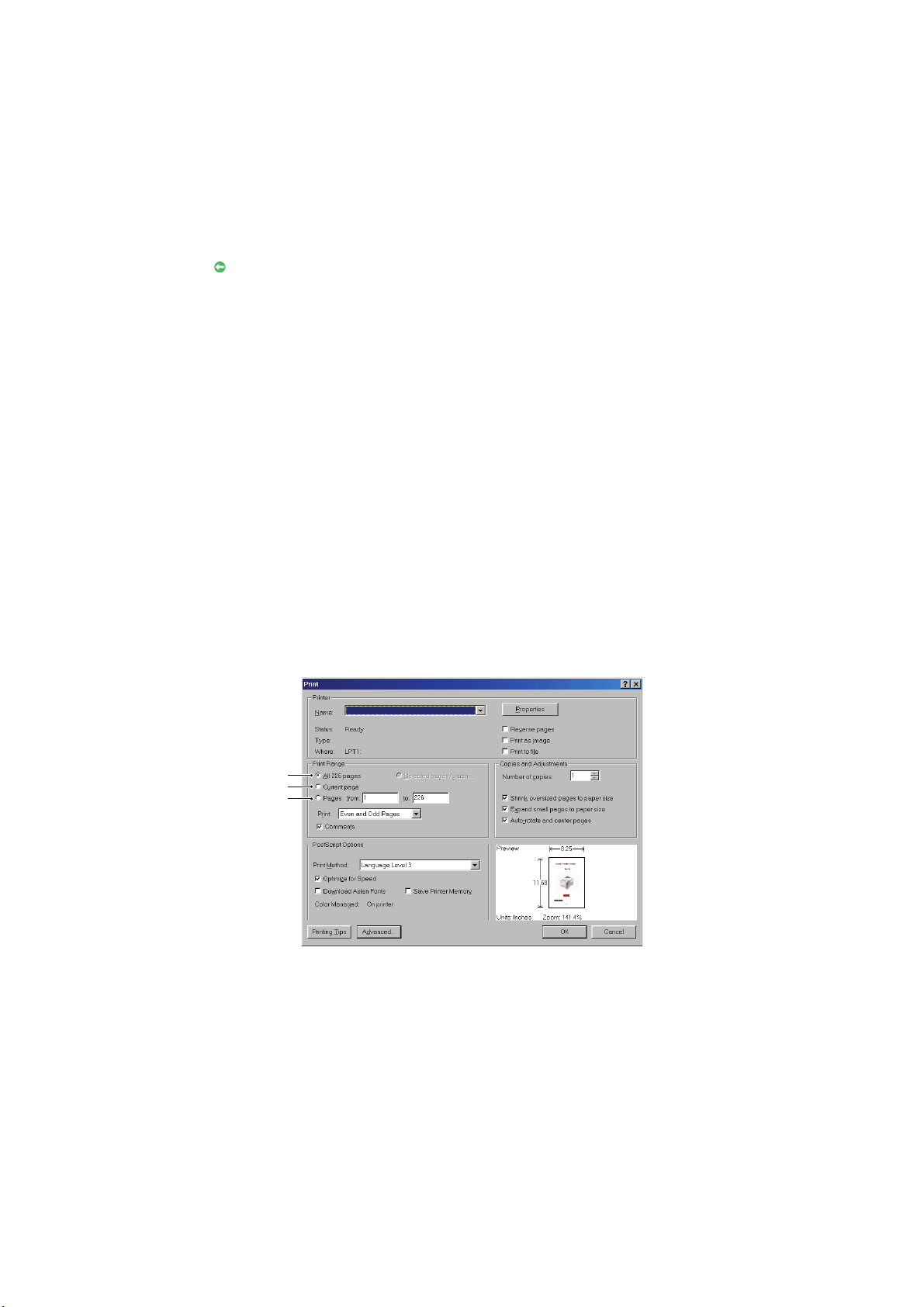
P
RINTING PAGES
The whole manual, individual pages, or sections may be printed. The procedure is:
1. From the toolbar,
2. Choose which
(a) All pages, (1)
select File > Print (or press the Ctrl + P keys).
pages you wish to print:
, for the entire manual.
(b) Current page, (2), for th
(c) Pages from and to, (3)
page numbers.
(d) Click OK.
e page at which you are looking.
, for the range of pages you specify by entering their
About this guide > 8
Page 9
G
7
8
9
5
10
3
4
1
2
6
ETTING STARTED
O
VERVIEW
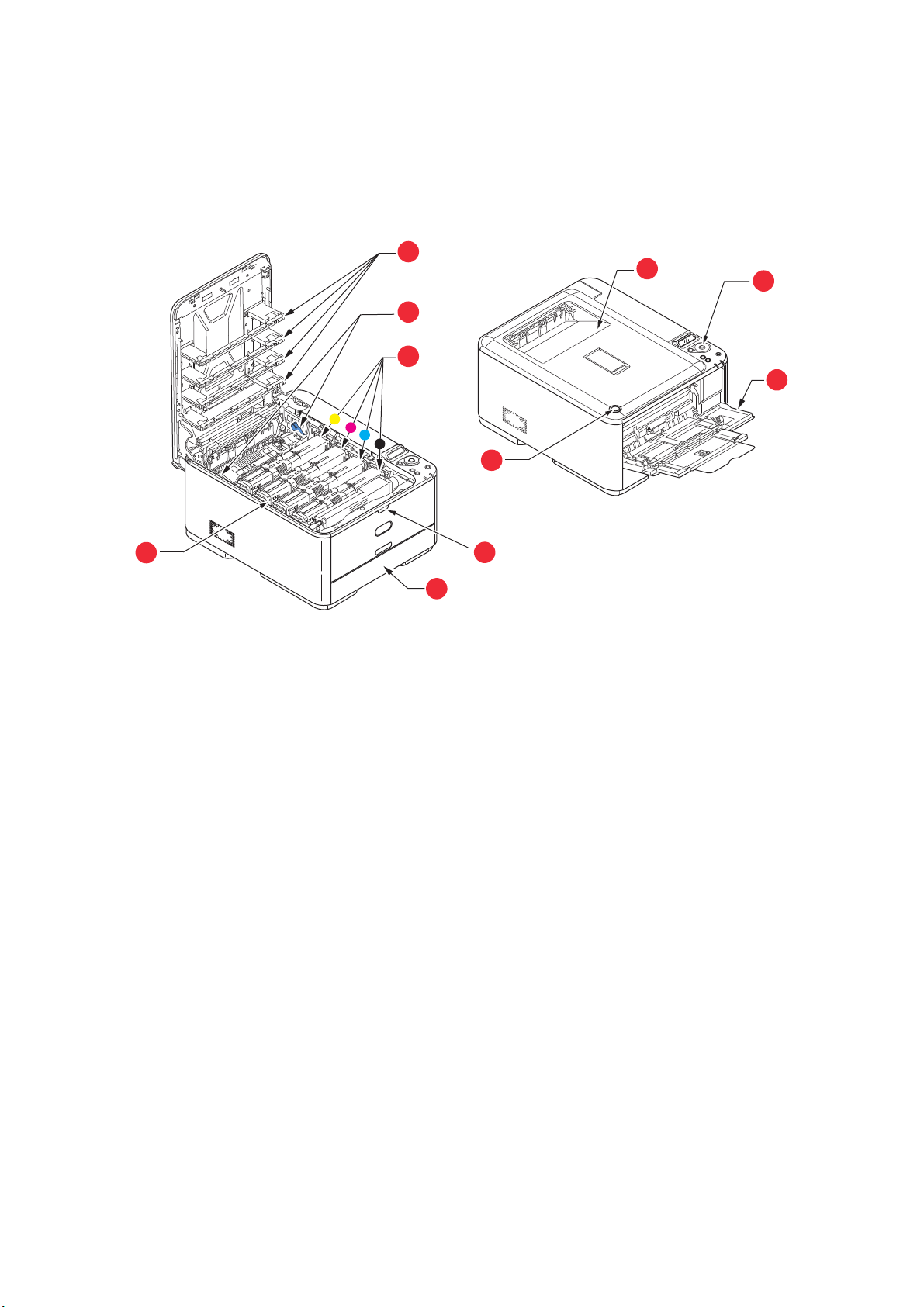
F
RONT VIEW
1. Output tray (face down stacker).
Standard printed copy delivery
up to 150 sheets at 80g/m².
2. Operator panel.
Menu driven operator controls and LCD
a
.
panel
3. Paper tray.
Standard paper tray. Holds up to 250 sheets
of 80g/m²
4. Multi purpose tray.
Used for feeding heavier paper stocks,
ve
en
manual feeding of single sheets when
required.
a. The display language can be changed to show different languages. (see “Changing the
paper.
lopes and other special media. Also for
display language” on page 10).
point. Holds
5. Multi-purpose tray release recess.
6. Output tray release button.
7. LED heads.
8. Fuser release levers.
9. Toner cartridges (C,M,Y,K).
10. ID unit.
Getting Started > 9
Page 10
R
1
2
5
4
3
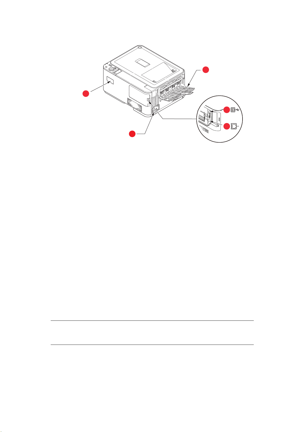
EAR VIEW
1. AC power socket.
2. Rear output tray (face up stacker).
3. USB interface.
a. The Network Interface may have a protective “plug” which
must be removed before connection can be made.
4. Network interface.
5. Wireless LAN I/F Cover.
a
When the rear paper stacker is folded down paper exits the printer through the rear of the
printer and is stacked here face up. This is mainly used for heavy print media. When used
in conjunction with the multi purpose feed tray, the paper path through the printer is
essentially straight. This avoids bending the paper around curves in the paper path and
enables feeding of up to 220g/m² media.
C
HANGING THE DISPLAY LANGUAGE
The default language used by your machine for display messages is English. If required, this
can be changed using the operator panel to display
LANGUAGE SETUP
S
WITCHING ON
.
ADMIN SETUP > OTHERS SETUP >
1. Plug the power cable into the power socket of your machine.
2. Plug the power cable into the electric socket.
3. Press the power sw
itch ON.
S
WITCHING OFF
Hold down the power switch for approximately one second.
NOTE
A message displays on the LCD screen and power switch indicator blinks, then
the printer switches OFF automatically.
W
IRELESS MODULE
C332dnw comes with a Wireless LAN Module as standard, but the Wireless LAN Module is
set to Disable by default. To enable the Wireless LAN Module, refer to “Wireless LAN
Module” on page 65.
Getting Started > 10
Page 11

E
NERGY SAVING SETTINGS
P
OWER SAVING MODE
If you do not use the machine for a while, it will enter the power saving mode to control
the power consumption of the device. To cancel or initiate power saving mode, press the
POWER SAVE button on the control panel. The POWER SAVE button illuminates while in
Power Save Mode.
NOTE
By default, the time interval to enter power saving mode is set to 1 minute.
You can change the time interval by pressing the MENU buttons on the control
panel. Then select MENUS > SYSTEM ADJUST > POW SAVE TIME.
S
LEEP MODE
Your machine transitions from power saving mode to sleep mode after a set period of time.
In sleep mode the power consumption of the device is minimal. The POWER SAVE button
blinks while in sleep mode.
NOTE
> The machine will not enter sleep mode if an error occurs and the machine
requires attention.
> By default, the time interval to
can change the time interval by pressing the MENU buttons on the control
panel. Then select MENUS > SYSTEM ADJUST > SLEEP TIME.
> It will automatically switch from Slee
network environment with a large number of packets flows, your
computer may respond by automatically switching from Sleep mode to
Power Save Mode. After a period of time has elapsed, the computer will
automatically enter into Sleep Mode.
enter sleep mode is set to 15 minutes. You
p Mode to Power Save Mode. In a
R
ETURNING TO STANDBY MODE
To return the machine to standby mode from power save or sleep mode, press the POWER
SAVE button on the control panel.
NOTE
n your machine receives a print
Whe
mode.
job, it automatically returns to standby
Getting Started > 11
Page 12

P
APER RECOMMENDATIONS
Your printer will handle a variety of print media, including a range of paper weights and
sizes, labels and envelopes. This section provides general advice on choice of media, and
explains how to use each type.
The best performance will be obtained when usin
for use in copiers and laser printers.
Use of heavily embossed or very rough textured p
Pre-printed stationery can be used, but the i
fuser temperatures used in the printing process.
Envelopes
nk must not offset when exposed to the high
CAUTION!
Envelopes should be free from twist, curl or other deformations.
They should also be of the rectangular flap type, with glue that
remains intact when subjected to hot roll pressure fusing used in
this type of printer. Window envelopes are not suitable.
Labels
CAUTION!
Labels should also be of the type recommended for use in copiers
and laser printers, in which the base carrier page is entirely
covered by labels. Other types of label stock may damage the
printer due to the labels peeling off during the printing process.
g standard 75~90g/m² paper designed
aper is not recommended.
Paper recommendations > 12
Page 13

C
ASSETTE TRAYS
SIZE DIMENSIONS WEIGHT (G/M²)
a
A6
A5 148 x 210mm
B5 182 x 257mm
a
B6
B6 half 64 x 182mm
Executive 184.2 x 266.7mm
A4 210 x 297mm
Letter 215.9 x 279.4mm
Legal 13in. 216 x 330mm
Legal 13.5in. 216 x 343mm
Legal 14in. 216 x 356mm
Statement
8.5in.SQ 216 x 216mm
Folio 210 x 330mm
Custom
COM-9 Envelope
COM-10 Envelope
Monarch Envelope
DL Envelope
C5 Envelope
4 x 6inch (4 x 6)
5 x 7inch (5 x 7)
Index Card
a. A6, B6 and Statement printing from Tray 1 or the MP tray only.
b. This paper size can be printed from the MP Tray onl
105 x 148mm Light 64 - 74g/m²
Medium Light 75 - 82g/m²
Medium 83 - 104g/m²
128 x 182mm
a
b
139.7 x 216mm
b
98.4 x 225.4mm
b
104.8 x 241.3mm
b
98.4 x 190.5mm
b
110 x 220mm
b
162 x 229mm
(3 x 5)
Heavy 105 - 120g/m²
Ultra heavy1 121 - 176g/m²
Ultra heavy2 177 - 220g/m²
Tray 1/2: 64 - 176g/m²
MP tray: 64 - 220g/m²
Duplex: 64 - 176g/m²
y.
If you have identical paper stock loaded in another tray (2nd tray if you have one, or multi
purpose tray) you have the printer automatically switch to the other tray when the current
tray runs out of paper. When printing from Windows applications, this function is enabled
in the driver settings. When printing from other systems, this function is enabled in the
Print Menu. (See “AUTO TRAY SWITCH” on page 29.)
Paper recommendations > 13
Page 14

M
ULTI PURPOSE TRAY
The multi purpose tray can handle the same sizes as the cassette trays but in weights up
to 220
the paper path through the printer is almost straight.
The multi purpose tray can feed paper widths from 64mm to 216mm and lengths from
127mm to 1321mm (banner printing).
For paper lengths exceeding 356mm (Legal 14in.) use paper stock between 90g/m² and
128g/m² and rear output tray (face up).
Use the multi purpose tray for printing on envelopes. Up to 10 envelopes can be loaded at
one time, subject to a maximum stacking depth of 10mm.
O
Output tray on the top of the printer can hold up to 150 sheets of 80g/m² standard paper,
and can handle paper stocks up to 176g/m².
Pages printed in reading order (page 1 first) will be sorted in reading order (last page on
top, facing down).
The number of sheets that can be stacked on the face down stacker may vary depending
on environment.
R
g/m². For very heavy paper stock use rear output tray (face up). This ensures that
UTPUT TRAY (FACE DOWN
EAR OUTPUT TRAY (FACE UP
)
)
Rear output tray at the rear of the printer should be opened and the tray extension pulled
out when required for use. In this condition paper will exit via this path, regardless of driver
settings.
Rear output tray can hold up to 100 sheets of 80g/m² standard paper, and can handle
stocks up to 220
Always use this stacker and the multi purpose feeder for paper stocks heavier than
176g/m².
D
UPLEX
Automatic two-sided printing on the same range of paper sizes as tray 2 (i.e. all cassette
sizes except A6), using paper stocks from 64 - 176g/m².
g/m².
Paper recommendations > 14
Page 15
L
OADING PAPER
C
ASSETTE TRAYS
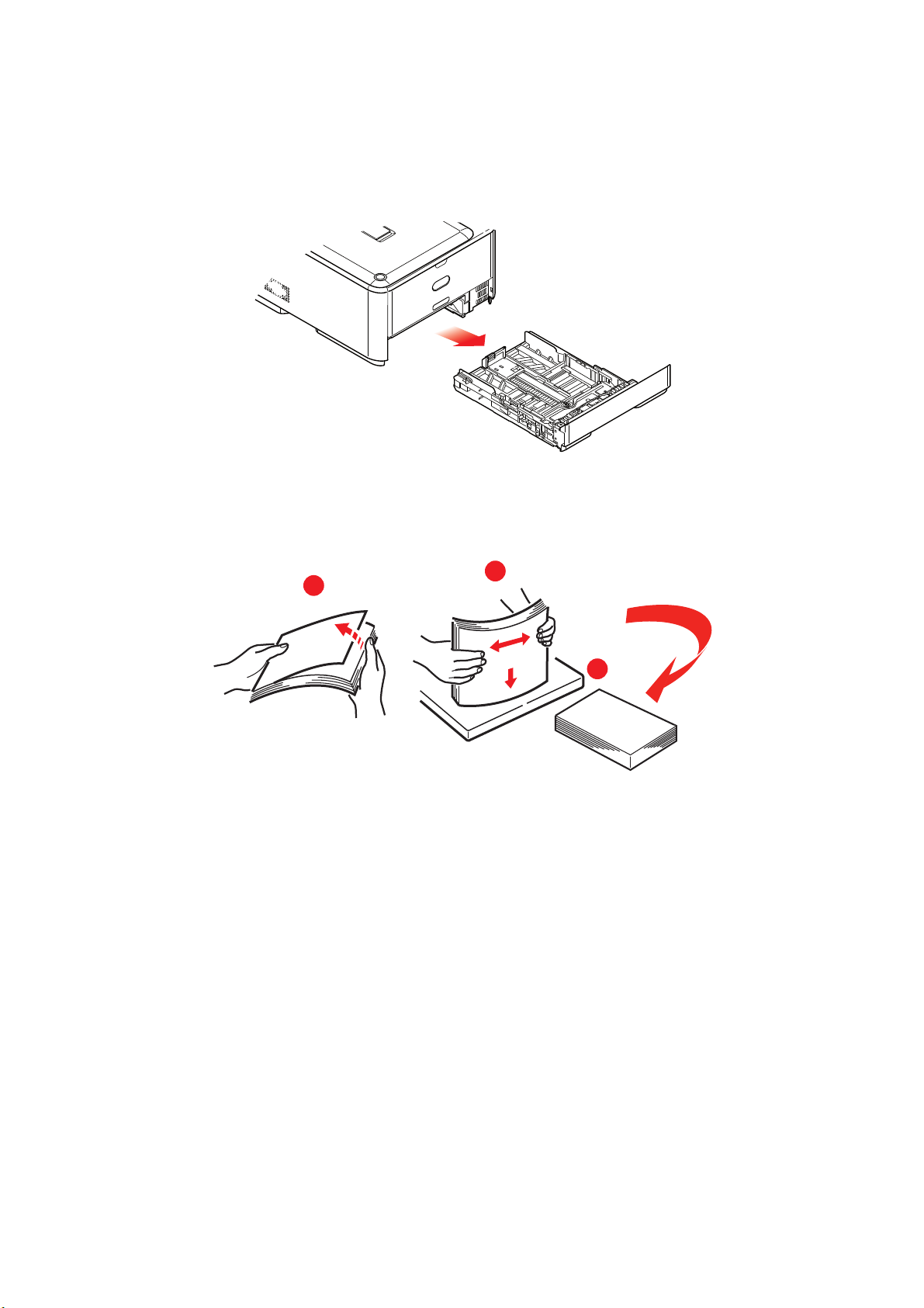
1. Remove the paper tray from the printer.
Fan the paper to be loaded at the edges (1) and in the middle (2) to ensure that all
2.
sheets are properly separated, then tap the edges of the stack on a flat surface to
make it flush again (3).
1
2
3
Loading paper > 15
Page 16
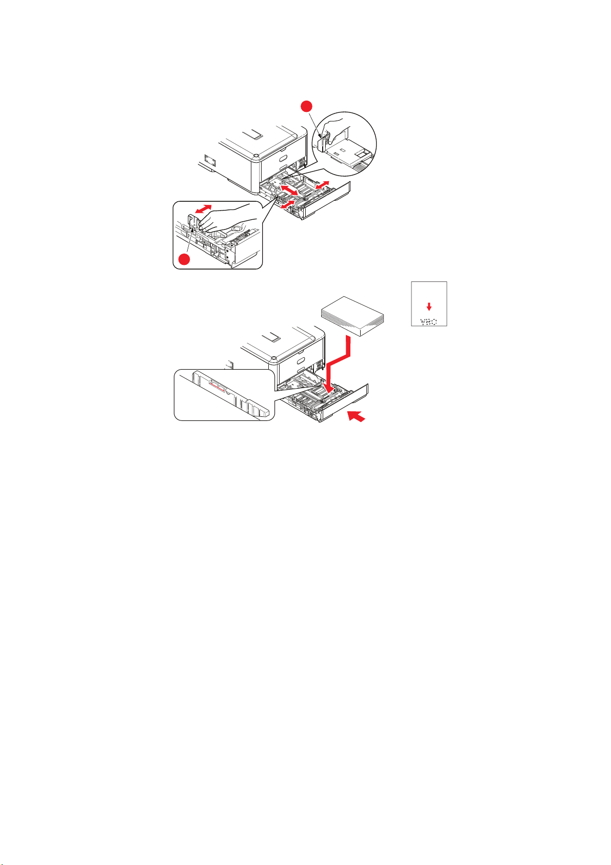
3. Load paper (letter headed paper face down and top edge towards the front of the
a
b
printer), as shown.
4. Adjust the rear stopp
er (a) and paper guides (b) to the size of paper being used.
5. Close the paper tray gently.
To prevent
> Do not leav
> Do not ov
> Do not load da
paper jams:
e space between the paper and the guides and rear stopper.
erfill the paper tray. Capacity depends on the type of paper stock.
maged paper.
> Do not load paper of different sizes or types at the same time.
> Close the paper tray gently.
Loading paper > 16
Page 17
> Do not pull the paper tray out during printing (except as described below for the 2nd
b
a
tray).
NOTE
> If you have two trays and you are printing from the 1st (upper) tray, you
can pull out the 2nd (lower) tray during printing to reload it. However, if
you are printing from the 2nd (lower) tray, do not pull out the 1st (upper)
tray. This will cause a paper jam.
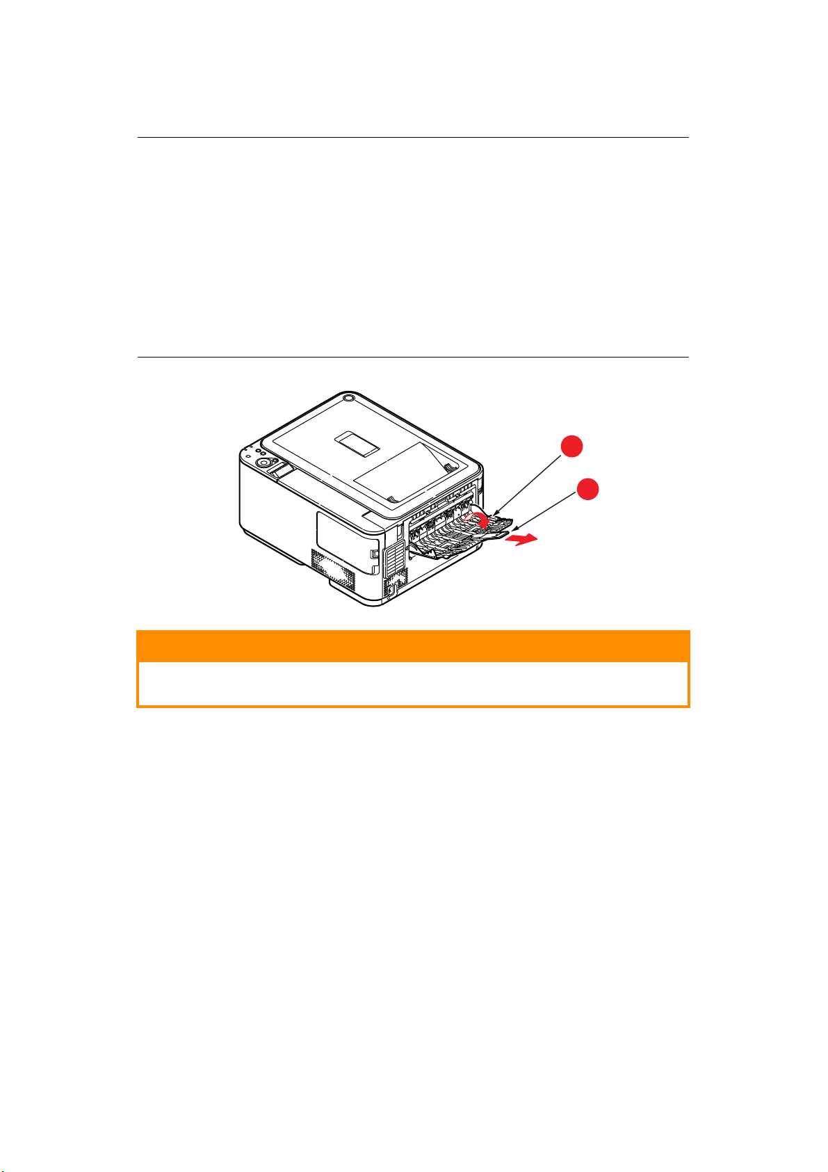
or face down printing, make sure rear output tray (a) is closed (the
> F
paper exits fro
approximately 150 sheets, depending on paper weight.
or face up printing, make sure rear output tray (a) is open and the paper
> F
support (b) is e
capacity is approximately 100 sheets, depending on paper weight.
> Always use the face up (rear) stacker for heavy
m the top of the printer). Stacking capacity is
xtended. Paper is stacked in reverse order and tray
paper (card stock, etc.).
CAUTION!
Do not open or close the rear paper exit while printing as it may
result in a paper jam.
Loading paper > 17
Page 18
M
b
d
d
c
a
ULTI PURPOSE TRAY
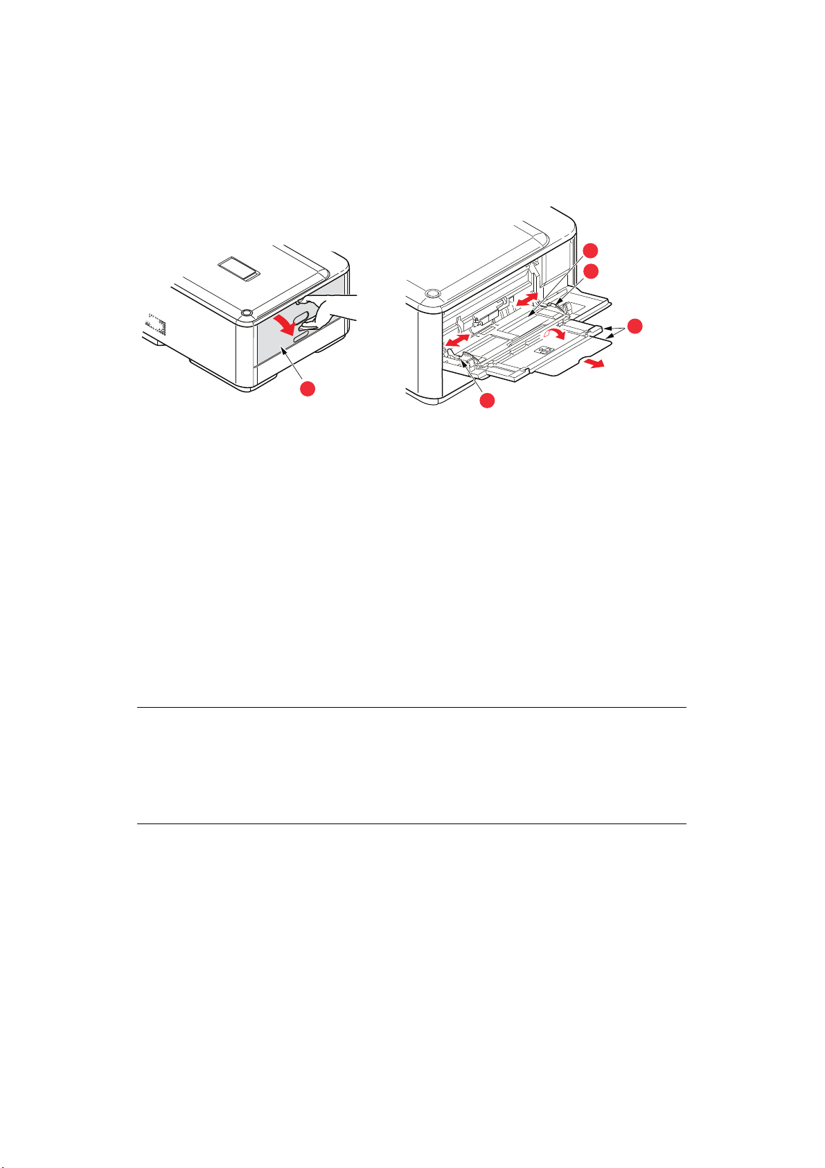
1. Open the multi purpose tray (a).
2. Fold out the paper supports
3. Press gently
4. Load the pap
down on the paper platform (c) to ensure it is latched down.
er and adjust the paper guides (d) to the size of paper being used.
(b).
> For single-sided printing on headed paper load the paper into the multi purpose
tr
ay with pre-printed side up and top edge into the printer.
> For two-sided (duplex) printing on headed paper lo
ad the paper with pre-printed
side down and top edge away from the printer.
> Envelopes should be loaded face up with top edge
to the left and short edge into
the printer. Do not select duplex printing on envelopes.
> Do not exceed the paper capacity of about 100 sheets or 10 envelopes. Maximum
stacki
ng depth is 10mm.
5. Press the tray
latch button inwards to release the paper platform, so that the paper
is lifted and gripped in place.
6. Set the correct paper size for the multi
NOTE
> Do not pr
the printer is printing from the MP tray. If you want to stop printing, open
the output tray.
or instructions on how to remove the paper, refer to “Clearing paper
> F
jams” on p
ess the paper from the top or pull the paper by holding it while
age 71.
purpose tray in the Media Menu.
Loading paper > 18
Page 19

O
PERATION
For full details of how to use the machine and any optional accessories to print jobs
efficiently and effectively, please refer to the Printing Guide and the Barcode Guide.
Operation > 19
Page 20
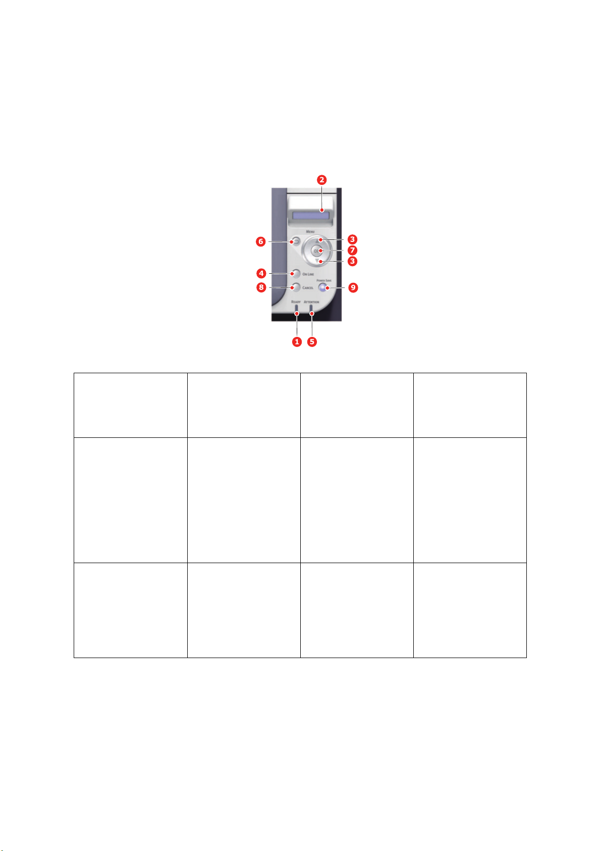
M
ENU FUNCTIONS
This section lists the menus accessed via the controls on the printer’s operator panel and
displayed in the LCD window.
O
PERATOR PANEL
1. READY LED ON: Ready to receive
3. MENU Buttons In the ONLINE or
5. ATTENTION LED ON: A w
data.
BLINKING: Proce
data.
OFF: Offline.
OFFLINE mode: enters
Menu m
the
In the Menu mode
forwards or reverses the
menu item displayed.
Press for 2 secs. or
onger to fast fo
l
reverse.
arning occurs.
Printing ma
(e.g low toner).
BLINKING: An error
rs. P
occu
possible (e.g. toner
empty).
OFF: N
rinting not
ormal condition.
ssing
ode.
:
rward or
y be possible
SPLAY Displays the printer
2. DI
4. ON LINE Button Switches between
BACK Button Returns to the previous
6.
status and an
messages.
LIN
ON
Exits the menu and goes
NLINE when pressed in
O
the
Menu mode.
Forces printing on the
paper currentl
when
pressed with
“WRONG PAPER” or
“WRONG PAPER SIZE”
displayed.
higher
y error
E and OFFLINE.
y loaded
level menu item.
Menu functions > 20
Page 21
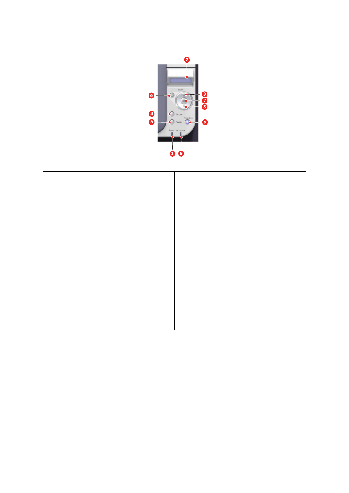
7. OK Button In the Menu mode:
nes the setting
ng this button
ower save state.
KING: Slee
p state.
9. POWER SAVE
Button &
LED
determi
selected.
Pressi
switches the machine
into power save mode or
wakes the machine up
from power save mode.
ON: P
BLIN
OFF: When it is not
sleep or power sav
either.
e,
8. CANCEL Button Deletes the data being
printed or received when
pressed for two seconds
or longer.
Deletes the data when
d for two seconds
esse
pr
or longer with WRONG
PAPER SIZE, RUN OUT
OF PAPER, TRAY 1 IS
OPEN, or TRAY 1 IS NOT
FOUND is displayed.
Exits the menu and goes
NLINE when pressed in
O
Menu mode.
the
Operator panel > 21
Page 22

H
OW TO CHANGE THE SETTINGS
It s hou l d be not e d th a t ma ny o f t hes e se t tin gs can be, and often are, overridden by settings
in the Windows printer drivers. However, several of the driver settings can be left at
“Printer Setting”, which will then default to the settings entered in these printer menus.
Where applicable, factory default settings are shown in bold type in the following tables.
In the normal operating condition, known as “standby,” the printer’s LCD window will show
“ONLINE.” In this condition, to enter the menu system, press the up and down Menu
buttons on the operator panel to move up and down through the list of menus until the
menu you wish to view is displayed. Then proceed as follows:
1. Use the up and down MENU buttons on the control panel to scroll through the
menus. When the item you want to change is displayed, press OK to view the submenus for that item.
2. Use the up and down MENU buttons to move up and down through the sub-menu
items. When the item you want to change is displayed press OK to display the
setting.
3. Use the up and down MENU buttons to move up and down through the available
settings for the sub-menu item. When the item you want to change is displayed
press OK to display the setting. An asterisk (*) will appear next to the setting,
indicating that this setting is currently in effect.
4. Do one of the following:
-
USER
> Press BACK again to move up to the list of menus;
or…
> Press ON LINE or CANCEL to exit from the menu system and return to standby.
H
OW TO CHANGE THE SETTINGS
You can set whether to ENABLE or DISABLE each category in the user menu.
Disabled categories are not displayed in the User’s menu. Only a system administrator can
change these settings.
1. Press up or down on the operator panel to display ADMIN SETUP.
2. Press the OK button.
3. At the Enter Password prompt, enter the Admin password:
(a) Using the up and down MENU buttons, scroll to the required letter/digit.
(b) Press the OK button to input and move to the next letter/digit.
(c) Repeat steps (a) and (b) until all letters/digits are entered.
Enter your 6 to 12 digit password.
(The default password is 999999.)
4. Press the OK button.
-
ADMINISTRATOR
5. Press the up or down MENU button until the “category” you want to change is
displayed.
6. Press the OK button.
7. Press the up or down MENU button until the “item” you want to change is displayed.
8. Press the OK button.
9. Using the up or down MENU button, identify the parameter as required.
10. Press the OK button to enter an asterisk (*) on the right side of the setting selected.
Operator panel > 22
Page 23
11.
M
ENUS
Press the
ON LINE
button to switch to online. The machine will automatically re-boot.
NOTE
This guide is written to cover a number of models and as such may reference
menu items or features that your machine does not have installed or does not
support.
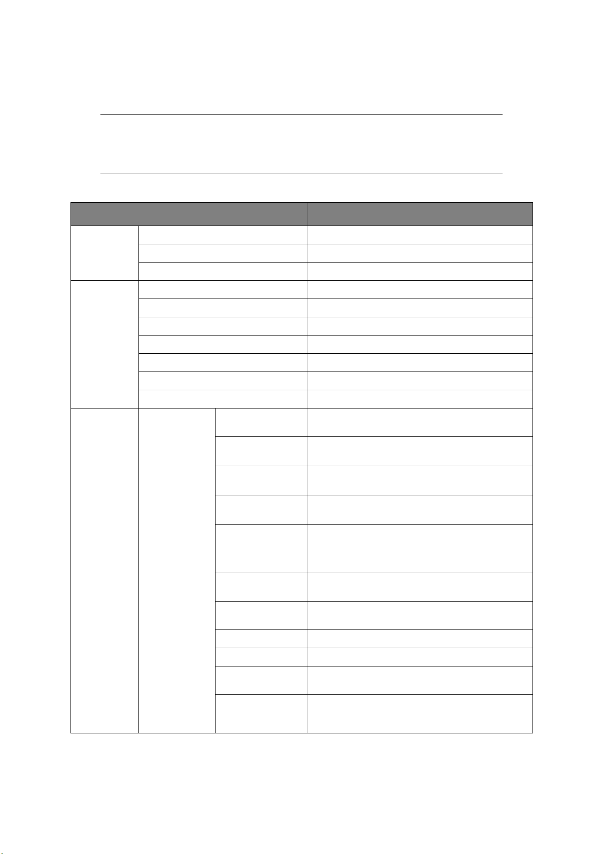
C
ONFIGURATION
ITEM EXPLANATION
TRAY COUNT MP TRAY The total number of pages fed from MP tray.
TRAY1 The total number of pages fed from tray 1.
TRAY2 The total number of pages fed from tray 2.
fe remaining.
SUPPLIES
LIFE
DRUM UNIT LIFE Percentage of image drum un
BELT LIFE Percentage of belt life remaining.
FUSER LIFE Percentage of fuser life remaining.
K TONER K toner residual quantity.
C TONER C toner residual quantity.
it li
M TONER M toner residual quantity.
Y TONER Y toner residual quantity.
NETWORK NETWORK INFO PRINTER NAME Displays “Printer Name” (a printer name used in DNS
SHORT NAME
ENABLING DEFAULT
GATEWAY
WIRED
IPV4 ADDRESS
SUBNET MASK Current assigned subnet mask. To change, proceed
GATEWAY ADDRESS Current assigned gateway address. To ch
MAC ADDRESS Displays the MAC address of the network with a wire.
NETWORK VERSION
*
et
work PnP) of the network with a wire.
or N
Displays “Short Printer Name” (a printer name used as
NetBEUI Computer Name) of the network with a wire.
Displays the valid default gateway.
Displays the status (
LAN.
Current assigned IP address. To change, press OK and
MENU
use
OK
has been set, press
as above.
proceed as abov
Displays the version of F/W of the network with a wire.
buttons to increment 1st octet, then press
again to move on to next octet. When 4th octet
ENABLE/DISABLE
OK
again to register new address.
e.
) of the wired
ange,
WEB VERSION Displays the version of WebPage of the network with
IPV6 LOCAL Displays the local IPv6 address. This menu is not
*:
If the Wireless LAN Module is fitted. C332dnw comes with a Wireless LAN Module as standard, but the Wireless LAN
Module is set to Disable by default. To enable the Wireless LAN Module, refer to “Wireless LAN Module” on page 65.
Operator panel > 23
a wire.
displaye
SETUP > NETWORK SETUP > TCP/IP.
d when DISABLE is selected for ADMIN
Page 24
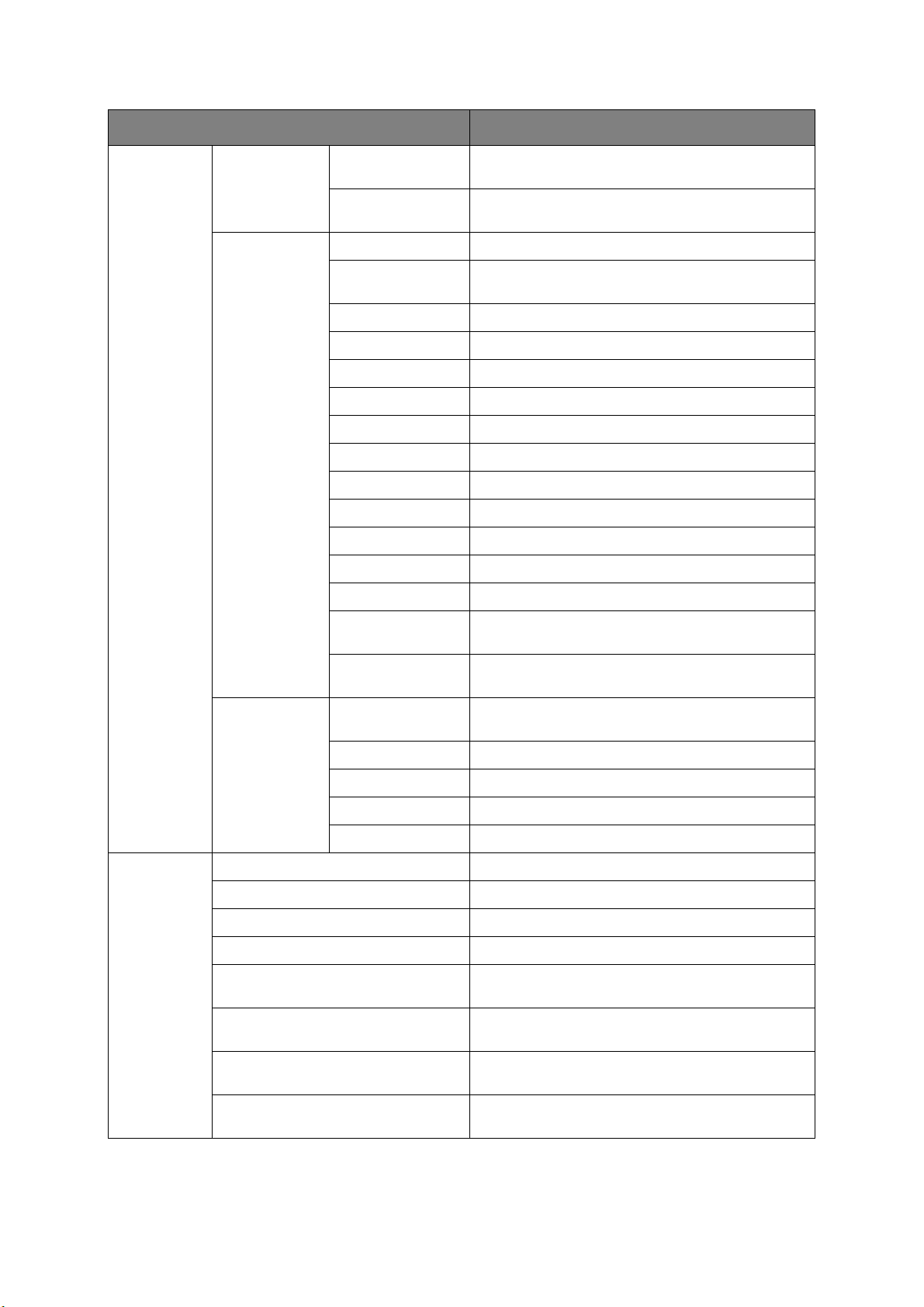
ITEM EXPLANATION
NETWORK
(cont.)
NETWORK INFO
(cont.)
WIRELESS
(INFRASTRUCTURE)
*
INFO
IPV6 STATELESS Displays the IPv6 Address (Stateless Address) of the
network.
IPV6 STATEFUL Displays the IPv6 Address (Stateful Address) of the
network.
FW VERSION Displays the version of Wireless LAN Firmware.
WIRELESS
(INFRASTRUCTURE)
Displays the status (ENABLE/DISABLE) of the
wireless LAN (Infrastructure mode).
SSID SSID of connection
SECURITY Displays the security type of wireless LAN.
STATE Displays the state of wireless LAN.
BAND Displays the using band of wireless LAN.
CHANNEL Display the using channel of wireless LAN.
RSSI Display the RSSI by percent.
IPV4 ADDRESS Displays the IPv4 Address of the network.
SUBNET MASK Displays the Subnet Mask of the network.
GATEWAY ADDRESS Displays the Gateway Address of the network.
MAC ADDRESS Displays the MAC Address of the printer.
IPV6 LOCAL Displays the IPv6 Address (Local) of the network.
IPV6 STATELESS Displays the IPv6 Address (Stateless Address) of the
network.
IPV6 STATEFUL Displays the IPv6 Address (Stateful Address) of the
network.
WIRELESS (AP
MODE) INFO
*
WIRELESS (AP MODE)
Displays the status (ENABLE/DISABLE) of the
wireless LAN (AP mode).
SSID Displays the SSID of the connection destination.
PASSWORD
CONNECTED DEVICES
Appears when
Displays the number of connected devices.
AP MODE USER SETTING
is set to
IPV4 ADDRESS Displays the IPv4 address.
SYSTEM SERIAL NUMBER Displays the serial number of the printer.
ASSET NUMBER Displays the Asset Number.
LOT NUMBER Displays the Lot Number.
FW VERSION Displays the version number of Firmware.
CU VERSION Displays the version number of CU (Control Unit)
firmware.
PU VERSION Displays the version number of PU (Print Unit)
firmware.
RAM Displays the total size of all the RAM installed in the
printer.
ENABLE
.
FLASH MEMORY Displays the total size of all the Flash Memory
installed in the printer.
*: If the Wireless LAN Module is fitted. C332dnw comes with a Wireless LAN Module as standard, but the Wireless LAN
Module is set to Disable by default. To enable the Wireless LAN Module, refer to “Wireless LAN Module” on page 65.
Operator panel > 24
Page 25

P
RINT INFO
This menu provides a quick method of listing various items stored within the printer.
ITEM EXPLANATION
CONFIGRATION Prints complete menu listing with current settings shown.
NETWORK Prints Network configuration information.
DEMO PAGE Prints demonstration page containing graphics and text in color
and monochrome.
PRINT FILE LIST Prints a job file list.
PRINT PSE FONT Prints a font list of installed PostScript.
CL emulation and PCL barcode.
PRINT PCL FONT Prints a font list of installed
PRINT PPR FONT Prints a font list of IBMPPR.
PRINT FX FONT Prints a font list of EPSON FX.
USAGE REPORT Prints the total of JobLog.
SUPPLIES REPORT Prints the supplies report.
PRINT ERROR LOG Prints an error log.
COLOR TUNING Prints the pattern for the u
COLOR PROF LIST Prints a list of stored color profiles.
P
o adjust TRC.
ser t
JOB LOG Prints the Job history.
Operator panel > 25
Page 26

M
ENUS
ITEM SETTINGS EXPLANATION
TRAY
CONFIG
MP TRAY
CONFIG
PAPERSIZE A4
A5
A6
B5
B6
B6 Half
LEGAL14
LEGAL13.5
LEGAL13
LETTER
EXECUTIVE
STATEMENT
8.5“SQ
Folio
16K(184x260mm)
16K(195x270mm)
16K(197x273mm)
CUSTOM
INDEXCARD
4x6 INCH
5x7 INCH
COM-9 ENVELOPE
COM-10 ENVELOPE
MONARCH ENV
DL ENVELOPE
C5 ENVELOPE
HAGAKI
OUFUKUHAGAKI
NAGAGATA #3
NAGAGATA #4
YOUGATA #4
Selects the size of paper to be fed from the
lti purpose tray.
mu
For CUSTOM sett
and Y DIMENSION.
ing see X DIMENSION
X DIMENSION 64 MILLI
~
210 MILLIMETER
~
216 MILLIMETER
Y DOMENSION 127 MILLIMETER
~
279 MILLIMETER
~
297 MILLIMETER
~
356 MILLIMETER
~
1321 MILLIMETER
METER
Operator panel > 26
Specifies paper width of custom paper as a
alue.
lt v
defau
Sets a paper size at right angles to the paper
run direction.
Specifies paper length of custom paper as a
alue.
lt v
defau
Sets a paper size in the same direction as
paper run direction.
the
Page 27

ITEM SETTINGS EXPLANATION
TRAY
CONFIG
t.)
(con
MP TRAY
CONFIG
(cont.)
MEDIATYPE PLAIN
LETTERHEAD
LABELS
BOND
RECYCLED
CARD STOCK
ROUGH
ENVELOPE
GLOSSY
USERTYPE1
USERTYPE2
USERTYPE3
USERTYPE4
USERTYPE5
MEDIAWEIGHT LIGHT
MEDIUM LIGHT
MEDIUM
HEAVY
ULTRA HEAVY1
ULTRA HEAVY2
TRAY USAGE WHEN
MI
SMATCHIN
DO NOT USE
Selects the type of media to be fed from the
lti purpose tray so that the printer can
mu
adjust its internal parameters to better
accommodate the selected type of media.
Note: USERTYPEn are displayed only if
stered i
regi
Selects the media weight to
mult
If a document to be printed demands a paper
G
size not installed in the selected tray, the
printer can automatically feed from the multi
purpose tray instead.
If this function is not enabled, the printer will
stop and request the co
be loaded.
n the host PC/Server.
i purpose tray.
be fed from the
ze of paper to
rrect si
TRAY1
CONFIG
PAPERSIZE A4
A5
A6
B5
B6
LEGAL14
LEGAL13.5
LEGAL13
LETTER
EXECUTIVE
STATEMENT
8.5“SQ
Folio
16K(184x260mm)
16K(195x270mm)
16K(197x273mm)
CUSTOM
HAGAKI
X DIMENSION 100 MILLIMETER
~
210 MILLIMETER
~
216 MILLIMETER
ay
Selects the size of paper loaded in Tr
(upper tray if both trays installed).
For CUSTOM sett
Y DIMENSION.
Specifies paper width of custom paper as a
lt v
defau
Sets a paper size at right angles to the paper
run direction.
alue.
ing see X DIMENSION and
1
Operator panel > 27
Page 28

ITEM SETTINGS EXPLANATION
TRAY
CONFIG
(cont.)
TRAY1
CONFIG
(cont.)
Y DOMENSION 148 MILLIMETER
~
279 MILLIMETER
~
297 MILLIMETER
~
356 MILLIMETER
MEDIATYPE PLAIN
LETTERHEAD
BOND
RECYCLED
CARD STOCK
ROUGH
GLOSSY
USERTYPE1
USERTYPE2
USERTYPE3
USERTYPE4
USERTYPE5
MEDIAWEIGHT LIGHT
MEDIUM LIGHT
MEDIUM
HEAVY
ULTRA HEAVY1
Specifies paper length of custom paper as a
lt value.
defau
Sets a paper size in the same direction as the
paper run direction.
Selects the type of media loaded in this tray.
will help the printer to adjust its internal
This
operating parameters, such as engine speed
and fusing temperature, to better
accommodate the media to be fed.
For example, letterhead may benefit from a
slightly lower fusing temperature to ensure
that its
Note: USERTYPEn are displayed only if
registered in the host PC/Server.
Adjusts the printer for the weight of paper
st
ink does not offset.
ock loaded in this tray.
TRAY2
CONFIG
PAPERSIZE A4
A5
B5
LEGAL14
LEGAL13.5
LEGAL13
LETTER
EXECUTIVE
8.5“SQ
Folio
16K(184x260mm)
16K(195x270mm)
16K(197x273mm)
CUSTOM
X DIMENSION 148 MILLIMETER
~
210 MILLIMETER
~
216 MILLIMETER
Selects the size of paper loaded in Tr
(lower) if installed. For CUSTOM setting see X
DIMENSION and Y DIMENSION.
Specifies paper width of Custom paper as
default value.
Sets a paper size at right angles to the paper
run direction.
ay 2
a
Operator panel > 28
Page 29

ITEM SETTINGS EXPLANATION
TRAY
CONFIG
t.)
(con
TRAY2
CONFIG
(cont.)
Y DOMENSION 210 MILLIMETER
~
279 MILLIMETER
~
297 MILLIMETER
~
356 MILLIMETER
MEDIATYPE PLAIN
LETTERHEAD
BOND
RECYCLED
CARD STOCK
ROUGH
GLOSSY
USERTYPE1
USERTYPE2
USERTYPE3
USERTYPE4
USERTYPE5
MEDIAWEIGHT LIGHT
MEDIUM LIGHT
MEDIUM
HEAVY
ULTRA HEAVY1
Specifies paper length of Custom paper as a
lt value.
defau
Sets a paper size in the same direction as
paper run direction.
Selects the type of media loaded in this tray (if
stall
ed). This will help the printer to adjust its
in
internal operating parameters, such as engine
speed and fusing temperature, to better
accommodate the media to be fed.
For example, letterhead may benefit from a
ghtly
sli
that its ink does not offset.
Note: USERTYPEn are displayed only if
regi
Adjusts the printer for the weight of paper
s
lower fusing temperature to ensure
t
oc
stered i
n the host PC/Server.
k loaded in this tray (if installed).
the
STSTEM
ADJUST
PAPERFEED MP TRAY
TRAY1
TRAY2
AUTO TRAY SWITCH ON
OFF
TRAY SEQUENCE DOWN
UP
PAPER FEED TRAY
DUPLEX LAST PAGE SKIP BLANK PAGE
ALWAYS PRINT
POW SAVE TIME 1 MIN
2 MIN
3 MIN
4 MIN
5 MIN
10 MIN
15 MIN
30 MIN
60 MIN
Selects the default tray for paper
(upper), Tray 2 (lower, if installed) or MP tray
(multi purpose tray).
If two trays contain identical paper, the printer
switch
can
current tray runs out in the middle of a print
job.
Determines tray sequ
automatically switching.
When SKIP BLANK PAGE is
print job has an odd number of pages, the final
page will be printed as Simplex.
When ALWA
print job contains an odd number of pages, the
final page will be printed as Duplex.
Adjusts the idling time before the printer
toma
au
mode. In this mode power consumption is
reduced to a low level required to just keep the
printer operating and ready to receive data.
When a job is sent the printer will require a
warm-up time of up to 1 minute before
printing can begin.
to an alternative source when the
enc
e order when
YS PRINT is se
tically switches into power saving
feed, Tra
selected and a
lected and the
y 1
Operator panel > 29
Page 30

ITEM SETTINGS EXPLANATION
STSTEM
ADJUST
)
(cont.
SLEEP TIME 1 MIN
2 MIN
3 MIN
4 MIN
5 MIN
10 MIN
15 MIN
30 MIN
60 MIN
AUTO PW OFF TIME 1 HOURS
2 HOURS
3 HOURS
4 HOURS
8 HOURS
12 HOURS
18 HOURS
24 HOURS
SILENT MODE ON
OFF
Adjusts the power saving time before
printer automatically switches into sleep mode.
Sets the time to switch from idle state to Off
.
mode
ifies a print preparation operation when
Spec
ering standby status from Sleep mode.
ent
ON
: It is quiet as there is no print preparation.
OFF: There is a rotation noise of the image to
perform print preparation but you can start
first printing early.
the
ECO MODE ON
OFF
CLRABLE WARINING ONLINE
JOB
AUTO CONTINUE ON
OFF
MANUAL TIMEOUT OFF
30 SEC
60 SEC
ON: Pri
te
prescribed degrees, if the job is small.
OFF: P
the fus
When ONLINE,
requests for a different paper size, can be
cleared by pressing the ON LINE button.
When set to JOB, they are cleared when the
print job resumes.
Determines whether or n
automatically recover from a memory overflow
condition.
Specifies how many seconds the printer will
wait for paper to be fed before cancelling the
job.
nting starts even before the
mperature of the fuser reaches the
rinting starts after the temperature of
er reaches the prescribed degrees.
non-critical w
arnings, such as
the printer will
ot
Operator panel > 30
Page 31

ITEM SETTINGS EXPLANATION
STSTEM
ADJUST
)
(cont.
TIMEOUT INJOB OFF
5 SEC
10 SEC
20 SEC
30 SEC
40 SEC
50 SEC
60 SEC
90 SEC
120 SEC
150 SEC
180 SEC
210 SEC
240 SEC
270 SEC
300 SEC
TIMEOUT LOCAL 0 SEC
5 SEC
~
40 SEC
~
290 SEC
295 SEC
300 SEC
Specifies how many seconds the printer will
ait when received data pauses before forcing
w
a page eject.
In PostScript Emulation mode the jo
ca
ncelled if timeout occurs.
Sets how long each port is left opened after a
b is
complete. (The network is excluded.)
jo
b will be
TIMEOUT NET 0 SEC
5 SEC
~
90 SEC
~
290 SEC
295 SEC
300 SEC
LOW TONER CONTINUE
STOP
EMPTY COLOR TONER ALARM
CANCEL
JAM RECOVERY ON
OFF
ERROR REPORT ON
OFF
HEX DUMP EXECUTE Prints out data received from the host PC in
Sets how long the network port is left
r a job is complete.
afte
Specifies whether the printer should continue
print
ing even after a low toner condition is
detected.
Specifies the action when there is an empty
oner.
or t
col
Specifies whether the pri
jam reco
If ON, the printer will attempt to re-print any
pages lost due to a paper jam once th
has been cleared.
If ON,
a Po
Note: Applies tp PS & PCL XL only.
ex
h
Turning off the power supply switch restores
Normal Mode from HEX Dump Mode.
very after a paper jam has occurred.
the printer will print error details when
stScript Emulation error occurs.
adecimal Dump.
nter should perform
opened
e jam
Operator panel > 31
Page 32

ITEM SETTINGS EXPLANATION
PRINT
ADJUST
POSITION
ADJUST
MP
TRAYX ADJUST
Y
ADJUST
DUPLEX
X
ADJUST
DUPLEX
Y
ADJUST
+2.00MILLIMET
~
0.00MILLIMETER
~
-2.00MILLIMETER
+2.00MILLIMETER
~
0.00MILLIMETER
~
-2.00MILLIMETER
+2.00MILLIMETER
~
0.00MILLIMETER
~
-2.00MILLIMETER
+2.00MILLIMETER
~
0.00MILLIMETER
~
-2.00MILLIMETER
ER
Adjusts the position of a whole print image in
e direction perpendicular to the direction the
th
paper runs, that is horizontally, in 0.25 mm
increments.
Any parts of the print image that are outside
e printabl
th
be cropped.
Adjusts the position of a whole print image in
e direction
th
in 0.25 mm increments.
Any parts of the print image that are outside
e printabl
th
be cropped.
Adjusts the position of a whole print image in
e direction perpendicular to the direction the
th
paper runs, that is horizontally, in 0.25 mm
increments.
Any parts of the print image that are outside
e printabl
th
be cropped.
Adjusts the position of a whole print image in
e direction the paper runs, that is vertically,
th
in 0.25 mm increments.
Any parts of the print image that are outside
e printabl
th
be cropped.
e area as a result of this shift will
the paper runs, that is vertically,
e area as a result of this shift will
e area as a result of this shift will
e area as a result of this shift will
TRAY1 X
ADJUST
Y
ADJUST
DUPLEX
X
ADJUST
DUPLEX
Y
ADJUST
+2.00MILLIMETER
~
0.00MILLIMETER
~
-2.00MILLIMETER
+2.00MILLIMETER
~
0.00MILLIMETER
~
-2.00MILLIMETER
+2.00MILLIMETER
~
0.00MILLIMETER
~
-2.00MILLIMETER
+2.00MILLIMETER
~
0.00MILLIMETER
~
-2.00MILLIMETER
Adjusts the position of a whole print image in
e direction perpendicula
th
paper runs, that is horizontally, in 0.25 mm
increments.
Any parts of the print image that are outside
e printabl
th
be cropped.
Adjusts the position of a whole print image in
e direction
th
in 0.25 mm increments.
Any parts of the print image that are outside
e printabl
th
be cropped.
Adjusts the position of a whole print image in
e direction perpendicular to the direction the
th
paper runs, that is horizontally, in 0.25 mm
increments.
Any parts of the print image that are outside
e printabl
th
be cropped.
Adjusts the position of a whole print image in
e direction the paper runs, that is vertically,
th
in 0.25 mm increments.
Any parts of the print image that are outside
the printable area as a result of this shift will
be cropped.
e area as a result of this shift will
the paper runs, that is vertically,
e area as a result of this shift will
e area as a result of this shift will
r to the direction the
Operator panel > 32
Page 33

ITEM SETTINGS EXPLANATION
PRINT
ADJUST
)
(cont.
POSITION
ADJUST
(cont.)
TRAY2 X
ADJUST
Y
ADJUST
DUPLEX
X
ADJUST
DUPLEX
Y
ADJUST
+2.00MILLIMETER
~
0.00MILLIMETER
~
-2.00MILLIMETER
+2.00MILLIMETER
~
0.00MILLIMETER
~
-2.00MILLIMETER
+2.00MILLIMETER
~
0.00MILLIMETER
~
-2.00MILLIMETER
+2.00MILLIMETER
~
0.00MILLIMETER
~
-2.00MILLIMETER
Adjusts the position of a whole print image in
e direction perpendicular to the direction the
th
paper runs, that is horizontally, in 0.25 mm
increments.
Any parts of the print image that are outside
e printabl
th
be cropped.
Adjusts the position of a whole print image in
e direction
th
in 0.25 mm increments.
Any parts of the print image that are outside
e printabl
th
be cropped.
Adjusts the position of a whole print image in
e direction perpendicular to the direction the
th
paper runs, that is horizontally, in 0.25 mm
increments.
Any parts of the print image that are outside
e printabl
th
be cropped.
Adjusts the position of a whole print image in
e direction the paper runs, that is vertically,
th
in 0.25 mm increments.
Any parts of the print image that are outside
e printabl
th
be cropped.
e area as a result of this shift will
the paper runs, that is vertically,
e area as a result of this shift will
e area as a result of this shift will
e area as a result of this shift will
PAPER BLACK SET +2
+1
0
-1
-2
PAPERT COLOR SET +2
+1
0
-1
-2
SMR SETTING +3
+2
+1
0
-1
-2
-3
BG SETTING +3
+2
+1
0
-1
-2
-3
Used for small adjustments when you
exper
streaking in monochrome printing on white
paper.
Select a higher value to reduce fading, or a
lo
high density print areas.
As above, but for color printing.
Sets a correction value for uneven print
quali
variations in temperature and humidity or in
print density/frequency.
Sets a correction value for dark-colored paper
printing, to correct print variations caused by
variations in temperature and humidity or in
print density/frequency.
ce faded print or light specks /
ien
wer v
alue to reduce specks or streaking in
, to correct print variations caused by
ty
Operator panel > 33
Page 34

ITEM SETTINGS EXPLANATION
PRINT
ADJUST
)
(cont.
DRUM CLEANING ON
OFF
HIGH HUM. MODE OFF
ON
QUIET MODE ON
OFF
Sets whether to rotate the drum in idle prior to
printing in order to reduce any horizontal white
lines.
CAUTION: Each additional rotation will shorten
the ID l
Set i
c
Sets Off/On of the quiet printing mode.
ife by that amount.
f the paper curl after printing is
on
spicuous.
Operator panel > 34
Page 35

A
DMIN SETUP
This menu should only be changed by the System Administrators. In order to gain access
to this menu, follow the instructions in “How to change the settings - admin
istrator” on
page 22.
CATEGORY EXPLANATION
NETWORK SETUP You can check and change the setting items related to a network and server.
USB SETUP You can check and change the settin
PRINT SETUP You can check and change the setting items related to printing.
OR MENU You can check and change the setting items related to the print color.
COL
SETUP You can check and change the setting items related to the PS printer driv
PS
PCL SETUP You can check and change the setting items
XPS SETUP You can check and change the setting items
IBM PPR SETUP You can check and change the setting i
EPSON FX SETUP You can check and change the setting item
PANEL SETUP You can check and change the setting items related to the panel.
POWER SETUP You can check and change the sett
TRAY SETUP You can check and change the setting i
OTHERS SETUP You can check and change the oth
SETTINGS You can check and change the setting items related to setting values.
CHANGE
ASSW
ORD
P
You can check and change the setting items related to passwords.
g items related to USB.
related to the PCL printer driver.
related to the XPS printer driver.
tems related to IBM PPR.
s related to EPSON FX.
ing i
tems related to power.
tems related to trays.
er setting items.
er.
Operator panel > 35
Page 36

N
ETWORK SETUP
This menu controls the operation of the printer’s network interface.
ITEM SETTINGS EXPLANATION
ENABLING DEFAULT
GATEWAY
WIRED ENABLE
TCP/IP ENABLE
NETBIOS OVER TCP ENABLE
IP ADDRESS SET AUTO
IPV4 ADDRESS xxx.xxx.xxx.xxx Current assigned IP addres
SUBNET MASK xxx.xxx.xxx.xxx Current assigned subnet mask. To
GATEWAY ADDRESS xxx.xxx.xxx.xxx Current assigned gateway address. To ch
DHCPV6 xxx.xxx.xxx.xxx
WEB ENABLE
WIRED
WIRELESS
(INFRAS
DISABLE
DISABLE
DISABLE
MANUAL
DISABLE
TRUCTURE)
Enables or disables this network protocol.
Sets Enable/Disable of NetBIOS over TCP protocol.
Display Conditions: TCP/IP should be enabled.
Specifies whether IP address allocation is automatic
(DHCP) or manually assigned.
s. To ch
use MENU buttons to increment 1st octet, then press
OK again to move on to next octet. When 4th octet has
been set, press OK again to register new address.
above.
as a
bove.
Current assigned DHCPV6. To change, proceed as above.
Enables or disables Web config. facility.
ange, press OK and
change, pro
ceed as
ange, proceed
TELNET ENABLE
DISABLE
FTP ENABLE
DISABLE
IPSEC ENABLE
DISABLE
SNMP ENABLE
DISABLE
NETWORK SCALE NORMAL
SMALL
GIGABIT NETWORK ENABLE
DISABLE
Enables or disables Telnet config. facility.
Enables or disables communication via FTP.
Sets Enable/Disable of IPSec. Enable via the web.
ENABLE: IPSec is
DISABLE: IPSec is
Enables or disables SNMP protocol.
Selects network size.
When NORMAL is selected, pri
effectively, even when connected to a HUB that has a
spanning tree feature. However, printer start up time
gets longer when computers are connected with two or
three small LANs.
When SMALL i
two or three small LANs to a large LAN, but may not
work effectively when connected to a HUB that has a
spanning tree feature.
Sets whether to enable access with Gi
available.
not available.
nter can work
elected, computers can cover from
s s
gabit Ethernet.
Operator panel > 36
Page 37
ITEM SETTINGS EXPLANATION
HUB LINK SETTING AUTO NEGOTIATE
100BASE-TX FULL
100BASE-TX HALF
10BASE-T FULL
10BASE-T HALF
FACTORY DEFAULTS EXECUTE Reloads the settings present when the unit was setup
USB S
ETUP
Sets full or half duplex for communication via a network
b.
hu
When AUTO NEGOTIATE is s
automatically.
by the m
anufacturer.
et, negotiation is done
This menu controls the operation of the printer’s USB data interface.
ITEM SETTINGS EXPLANATION
USB ENABLE
DISABLE
SPEED 480 Mbps
12 Mbps
SOFT RESET ENABLE
DISABLE
SERIAL NUMBER ENABLE
DISABLE
Sets USB I/F Enable/Disable.
Selects the USB interface speed.
Enables or disables the SOFT RESET command.
Specifies whether to ENABLE or DISABL
number.
The USB serial number is used to identify the USB
device c
onnected to your PC.
E a USB serial
OFFLINE RECEIVE ENABLE
DISABLE
CONNECTED HOST NORMAL
SPECIFIC
P
RINT SETUP
Enables or disables this function. When set to Enable,
he
interface retains a receive possible state even when
t
switching to Offline. Interface sends the BUSY signal
only when the receive buffer is full or a service call
occurs.
This menu provides adjustment of various print job related functions.
ITEM SETTINGS EXPLANATION
PERSONALITY AUTO
EMULATION
PCL
XPS
IBM PPR III XL
EPSON FX
PS3 EMULATION
COPIES 1
~
999
Selects a printer language.
Enter the number of copies of a docu
printed from 1
to 999.
ment to be
DUPLEX ON
OFF
Switches the Duplex (2 sided) function ON/OFF
Operator panel > 37
.
Page 38

ITEM SETTINGS EXPLANATION
BINDING LONG EDGE
SHORT EDGE
MEDIA CHECK ENABLE
DISABLE
OVERRIDE A4/LT NO
YES
RESOLUTION 600 DPI
600 x 1200 DPI
600 DPI M-LEVEL
TONER SAVE TONER SAVE LEVEL OFF
LOW
MIDDLE
HIGH
TONER SAVE COLOR ALL
EXCEPT100%
BLACK
Sets the default binding to SEF or LEF.
Determines whether the printer check the size of
paper loaded matches that required for the
document sent to print.
If enabled, when the paper si
A4 but there is no A4 set in the printer, if there is
Letter paper in the printer, the job will be printed
on Letter paper without requesting the user to
fill the paper tray with A4 paper.
Similarly, when the paper size of a job is set to
ter but there is no Letter set in the printer, if
Let
there is A4 paper in the printer, the job will be
printed on A4 paper without requesting the user
to fill the paper tray with Letter paper.
Sets the default resolution for printing (dots per
inch).
Set the toner save level.
Specify toner save for 100% black.
All: Enables toner save for all colors.
Except 100% Black: Disabl
100% black.
ze of a job is set to
es toner save for
MONO-PRINT SPEED AUTO
COLOR SPEED
NORMAL SPEED
ORIENTATION PORTRAIT
LANDSCAPE
Sets the monochrome print speed. Prints at the
most appropria
AUTO is set.
Prints always at the color print speed if CO
SPEED is set.
Prints always at the monochrome print speed if
NORMAL SPEED is
Selects default page orientation between portrait
(tall) and landscape (wide). - (PCL, IBMPPR &
EPSON FX only)
te speed for page process if
LOR
set.
Operator panel > 38
Page 39

ITEM SETTINGS EXPLANATION
EDIT SIZE CASSETTE
SIZE
A4
A5
A6
B5
B6
B6 Half
LEGAL14
LEGAL13.5
LEGAL13
LETTER
EXECUTIVE
STATEMENT
8.5“SQ
Folio
16K(184x260mm)
16K(195x270mm)
16K(197x273mm)
CUSTOM
INDEXCARD
4x6 INCH
5x7 INCH
COM-9
OPE
ENVEL
COM-10
OPE
ENVEL
MONARCH ENV
DL ENVELOPE
C5 ENVELOPE
HAGAKI
OUFUKUHAGAKI
NAGAGATA #3
NAGAGATA #4
YOUGATA #4
Sets the size of the printable page area to match
e size of paper in use. This is not the same as
th
the physical paper size, which is always slightly
larger. For dimensions of physical page sizes, see
“Paper Recommendations” section in this guide.
(PCL/IBMPPR/EPSONFX only)
X DIMENSION 64
MILLIMETER
(2.5 INCH)
~
210
MILLIMETER
(8.3 INCH)
~
216
MILLIMETER
(8.5 INCH)
Specifies paper width of Custom paper as a
default v
Sets a paper size at right angles to the paper run
direction.
Note: The default setting varies depending on
the sales area.
Operator panel > 39
alue.
Page 40

ITEM SETTINGS EXPLANATION
Y DIMENSION 127
TRAPPING OFF
C
OLOR MENU
MILLIMETER
(5.0 INCH)
~
279
MILLIMETER
(11.0 INCH)
~
297
MILLIMETER
(11.7 INCH)
~
356
MILLIMETER
(14.0 INCH)
~
1321
MILLIMETER
(52.0 INCH)
NARROW
WIDE
Specifies paper length of Custom paper as a
default v
Sets a paper size in the same direction as the
paper run direction.
Note: The default setting v
the sales area.
Specifies the trapping value. Set it when there is
an empty gap between two colors.
alue.
aries depending on
The printer automatically adjusts color balance and density at appropriate intervals,
optimising the printed output for bright white paper viewed in natural daylight conditions.
The items on this menu provide a means of changing the default settings for special or
particularly difficult print jobs.
ITEM SETTINGS EXPLANATION
DENSITY CONTROL AUTO
MANUAL
ADJUST DENSITY EXECUTE
COLOR TUNING PRINT PATTERN
CYAN TUNING CYAN
CYAN MID-TONE -3~0~+3
CYAN DARK -3~0~+3
MAGENTA
TUNING
YELLOW
TUNING
MAGENTA HIGHLIGHT -3~0~+3
MAGENTA MID-TONE -3~0~+3
MAGENTA DARK -3~0~+3
YELLOW HIGHLIGHT -3~0~+3
YELLOW MID-TONE -3~0~+3
HIGHLIGHT
-3~0~+3 Adjusts image density for each color component
(cyan,magenta, yellow and black).
Normal setting is 0.
BLACK
TUNING
MYELLOW DARK -3~0~+3
BLACK HIGHLIGHT -3~0~+3
BLACK MID-TONE -3~0~+3
BLACK DARK -3~0~+3
Operator panel > 40
Page 41

ITEM SETTINGS EXPLANATION
COLOR
DENSITY
ADJUST REGSTRATION EXECUTE Performs automatic color registration
INK SIMULATION OFF
UCR LOW
CMY100% DENSITY ENABLE
CMYK CONVERSION ON
CYAN DENSITY -3~0~+3 Adjusts the density of each color
MAGENTA DENSITY -3~0~+3
YELLOW DENSITY -3~0~+3
BLACK DENSITY -3~0~+3
SWOP
ISO COATED
JAPAN
MEDIUM
HIGH
DISABLE
OFF
(cyan,magenta, yellow and black).
Normal setting is 0.
ustment.
adj
ormally this is done on power on and when
N
output tr
This process accurately align
and yellow images to the black image.
Selects from a range of industry standard color
swatc
Note: This function only applies to PS models
Selects limitation of the toner layer thickness.
If paper curl occurs in dark prin
MEDIUM or HIGH some
When enabled, black areas are produced using
1
This results in a glossier finish.
Setting to OF
process of CMYK data, which will reduce the
processing time.
This setting is ignored when Ink Simulation
fu
Note: This function only applies to PS models
ay is opened and then closed.
s th
.
hes
ting, selecting
times helps reduce curl.
00% C, M, and Y instead of black
F will
simplify the conversion
nction
is used.
e cyan, magenta
.
PS S
ETUP
ITEM SETTINGS EXPLANATION
L1 TRAY TYPE1
TYPE2
-PROTOCOL ASCII
NET PS
RAW
USB PS-PROTOCOL ASCII
RAW
PD
F PAPER SIZE CURRENT
TRAY S
SI
ZE IN PDF
FILE
SCALING SIZE
PDF SCALING SIZE 1%
~
99%
IZE
TYPE1: The tray selection number for the level 1
operator begins with 1.
TYPE2: The number begins with 0.
Specifies a communication protocol mode for PS
data from a network
Specifies a communication protocol mode for PS
data from
Select the paper size of
Specifies scaling size by percent
Size is set to Scaling Size.
USB.
.
PDF Direct Print.
when PDF Paper
Operator panel > 41
Page 42

PCL S
ETUP
ITEM SETTINGS EXPLANATION
FONT SOURCE RESIDENT Specifies the location of the PCL default font.
Normally this will be INTERNAL unless additional
fonts are installed in the expansion ROM slot or
additional fonts have been downloaded to RAM as
permanent fonts.
FONT NO. I0
~
I90
FONT PITCH 0.44 CPI
~
10.00 CPI
~
99.99 CPI
FONT HEIGHT 4.00 POINT
~
12.00 POINT
~
999.75 POINT
SYMBOL SET PC-8
(Default Symbol
t
Se
only shown)
A4 PRINT WIDTH 78 COLUMN
80 COLUMN
WHITE PAGE SKIP ON
OFF
Sets the current default fo
currentl
Sets the width of the PCL defaul
char
Default font is the fixed-pitch, scalable font. Th
value is displayed to the second decimal place.
Displayed only when the font selected in Font No.
i
Height of the PCL default font.
Note: This menu item is displayed only when the
f
spacing, scalable font.
Sel
Sets the number of columns subject to Auto LF
w
CR/LF Mode is set to OFF with the 10CPI
character.
Selects whether blank pages are printed or not.
y selected source.
acters/inch (CPI).
s fix
ed-spacing, scalable font.
ont sel
ected in Font No. is a proportional-
ects a PCL symbol set.
it
h A4 p aper in PCL. This i s the val ue when Auto
nt number from the
t font in
e
CR FUNCTION CR
CR+LF
LF FUNCTION LF
LF+CR
PRINT MARGIN NORMAL
1/5 INCH
1/6 INCH
TRUE BLACK ON
OFF
PEN WIDTH ADJUST ON
OFF
rr
Selects whether a received ca
character (0Dh) also causes a line feed.
Selects whether a received line feed character
(0Ah) al
Sets the non-printable page area. NORMAL is
PCL comp
PCL: Sets if to use Composite Black (CMYK
mixed) or Pure Bl
(100%) in image data.
When minimum width is specified in PCL,
somet
With PEN WIDTH AD
minimum width is specified, the line width will be
emphasized so as to look wider than a 1-dot line.
With PEN
will appear as before.
so causes a carriage return.
atible.
ack (K only) for the black
imes a 1-dot
WIDTH ADJUST set
line, looks broken.
JUST set to ON, when the
iage return
to OFF, the line
Operator panel > 42
Page 43

ITEM SETTINGS EXPLANATION
TRAY ID#
XPS S
ETUP
MP TRAY
TRAY1 1
TRAY2 1
1
~
4
~
59
~
59
~
5
~
59
Sets the # to specify the
feed destination command (ESC&l#H) in PCL5e
emulation.
Sets the # to specify Tray 1 for the paper feed
inati
dest
emulation.
Sets the # to specify Tray 2 for the paper feed
dest
emulation.
(Displayed only if Tray 2 is installed).
on command (ESC&l#H) in PCL5e
inati
on command (ESC&l#H) in PCL5e
ITEM SETTINGS EXPLANATION
DIGITAL SIGNATURE PRINT EVEN NG
PRINT ONLY OK
OFF
DISCARD CONTROL AUTO
EACH PAGE
OFF
Sets the DigitalSignature function.
Sets the DiscardControl function.
MP tray for the paper
MC MODE ON
OFF
UNZIP MODE AUTO
SPEED
PRINT
WHITE PAGE SKIP ON
OFF
Sets the MarkupComaptibility function.
Specifies the unzip method for XPS flies.
Sets whether or not to eject pages that contain
no print data (blank pages) using XPS
.
Operator panel > 43
Page 44

IBM PPR S
ETUP
ITEM SETTINGS EXPLANATION
CHARACTER PITCH 10 CPI
12 CPI
17 CPI
20 CPI
PROPORTIONAL
FONT CONDENSE
CHARACTER SET SET-2
SYMBOL SET IBM-437
LETTER O STYLE ENABLE
ZERO CHARACTER NORMAL
LINE PITCH 6 LPI
WHITE PAGE SKIP ON
12CPI TO 20CPI
12CPI TO 12CPI
SET-1
(Default Symbol
et onl
y shown)
S
DISABLE
SLASHED
8 LPI
OFF
Specifies character pitch i
Specifies 12CPI pitch for Condense Mode.
Specifies a character set.
Specifies a symbol set.
Specifies the style that replaces 9BH with letter o
and 9DH
Sets the zero to be slashed or unslashed.
Specifies the line spacing.
Selects whether blank pages are printed or not.
with
a zero.
n IBM PPR emulation.
CR FUNCTION CR
CR+LF
LF FUNCTION LF
LF+CR
LI
NE LENGTH 80 COLUMN
136 COLUMN
M LENGTH 11 INCH
FOR
11.7 INCH
12 INCH
TOF POSITION 0.0 INCH
0.1 INCH
~
1.0 INCH
LEFT MARGIN 0.0 INCH
0.1 INCH
~
1.0 INCH
FIT TO LETTER EN
ABLE
DISABLE
rr
Selects whether a received ca
character (0Dh) also causes a line feed.
Sets performance when LF code
Specifies the number of characters per line.
Specifies the length of paper.
Note: The default setting varies depen
sales area.
Specifies the distance of prin
paper.
of the
Specifies the distance of print from the left hand
edge of the paper
Sets the printing mode that can fit print data,
alent to 11 inches (66 lines), in the LETTER-
equiv
size printable area.
Note: The default setting v
sales area.
.
iage return
is received.
ding on the
t from the top edge
aries depen
ding on the
TEXT HEIGHT SAME
DIFF
Operator panel > 44
Sets the height of a character.
SAME: R
DIF
egardless of CPI, same height.
F: As CPI, charac
ter heights vary.
Page 45

EPSON FX S
ETUP
ITEM SETTINGS EXPLANATION
CHARACTER PITCH 10 CPI
12 CPI
17 CPI
20 CPI
PROPORTIONAL
CHARACTER SET SET-2
SET-1
SYMBOL SET IBM-437
(Default Symbol
y shown)
et onl
S
LETTER O STYLE ENABLE
DISABLE
ZERO CHARACTER NORMAL
SLASHED
LINE PITCH 6 LPI
8 LPI
WHITE PAGE SKIP ON
OFF
CR FUNCTION CR
CR+LF
Specifies character pitch in this emulation.
Specifies a character set.
Specifies a symbol set.
Specifies the style that replaces 9BH with letter o
and 9DH
Sets the zero to be slashed or unslashed.
Specifies the line spacing.
Selects whether blank pages are printed or not.
Selects whether a received carr
character (0Dh) also causes a line feed.
with
a zero.
iage return
LINE LENGTH 80 COLUMN
136 COLUMN
FOR
M LENGTH 11 INCH
11.7 INCH
12 INCH
TOF POSITION 0.0 INCH
0.1 INCH
~
1.0 INCH
LEFT MARGIN 0.0 INCH
0.1 INCH
~
1.0 INCH
FIT TO LETTER EN
TEXT HEIG
HT SAME
ABLE
DISABLE
DIFF
Specifies the number of char
Specifies the length of paper.
Note: The default setting varies depen
sales area.
Specifies the distance of prin
of the
paper.
Specifies the distance of print from the left hand
edge of the paper
Sets the printing mode that can fit print data,
equivalent to 11 inches (66 lines), in the LETTERsize prin
Sets the height of a character.
SAME: R
DIF
table area.
egardless of CPI, same height.
F: As CPI, charac
.
acters per line.
ding on the
t from the top edge
ter heights vary.
Operator panel > 45
Page 46

P
ANEL SETUP
ITEM SETTINGS EXPLANATION
NEARLIFE STATUS ENABLE
DISABLE
NEARLIFE LED ENABLE
DISABLE
P
OWER SETUP
Set LCD panel control at the time of near-life
warning for drum.
ENABLE: Dis
DISABLE: Do not d
Enables/disables illumination of front panel LED
when “near-end
drumoccurs.
Attention LED is lit when setting is enabled,
ibited when
inh
play a near-life warning.
disabled.
ITEM SETTINGS EXPLANATION
AUTO PW OFF ENABLE
AUTO CONFIG
DISABLE
Sets the Auto Power Off operation.
ENABLE: When the printer is no
period of time, it turns off the power
automatically.
AUTO CONFIG: Auto po
howev
er, the printer will not turn off the power
under the following conditions:
> An Ethernet cable is plugged to the network
nterface connection.
i
>
The wireless LAN is enabled.
Note: The default setting v
sales area.
isplay a near-life warning.
-of-life” warning of a toner or
t used for a
wer off is enabled,
aries depen
ding on the
POWER RETURN MANUAL
STATE
CONTINUE
T
RAY SETUP
Set the power on method after energi
ITEM SETTINGS EXPLANATION
UNIT OF MEASURE INCH
MILLIMETER
DEFAULT PAPERSIZE A4
LETTER
Selects the unit of measure.
Note: The default setting varies depen
sales area.
Set default paper size.
Note: The default setting v
sales area.
aries depen
ze
.
ding on the
ding on the
Operator panel > 46
Page 47

O
THERS SETUP
ITEM SETTINGS EXPLANATION
RAM SETUP RECEIVE BUF SIZE AUTO
0.5 MB
1 MB
2 MB
4 MB
8 MB
16 MB
32 MB
RESOURCE SAVE AUTO
OFF
0.5 MB
1 MB
2 MB
4 MB
8 MB
16 MB
32 MB
FLASH SETUP FLASH INITIALIZE EXECUTE Initialises the resident FLASH MEMORY.
FORMATTING PCL
COMMON
PS
ABLE INITIAL NO
STORAGE
TUP
SE
JOB LOG
SETUP
SECURITY
SETUP
LANGUAGE
SETUP
EN
CLEAR JOB
ACCES
LANG
LANGUAGE
IT
IN
LOG EXECUTE Clears the saved job logs.
S CONTROL ENABLE
UAGE SELECT ~
IALIZE
YES
DISABLE
ENGLISH
~
EXECUTE Initialize the message file loaded in FLASH.
Sets the size of the receive buffer.
Sets the size of the resource saving area.
is selected, the machine will go back to the
If NO
source
menu.
S is selected, the machine will be
If YE
auto
matically rebooted and initialize the FLASH
memory.
Format the specified partition. Press the OK
button an
ARE YOU SURE?
YES/NO
If NO i
source
automatically reboot and initialise the specified
partition.
Prevents a setting change accompanying
initialization of BlockDeveice(FLASH).
Displays the security setting menu.
Selects display language for the LCD panel.
d the fo
s selected, the display will go back to the
menu. If YES is selected, the printer will
llowing message displays.
Operator panel > 47
Page 48

ITEM SETTINGS EXPLANATION
JOB CANCEL
SETUP
NEARLIFE
SETUP
ERASE PRIVACY DATA EXECUTE Erase the registered privacy data and the stored
BUS. PHONE
SETUP
CANCEL KEY
BEHAVIOR
INQUIRY DISPLAY ON
FOCUS POSITION YES
DISPLAY TIMEOUT 60
DRUM NEARLIFE
FUSER NEARLIFE
BELT NEARLIFE
BUS. PHONE COOPE ENABLE
CONNECT ADDRESS 0.0.0.0
CONNECT PORT NO. 1
SHORT
LONG
OFF
OFF
NO
~
180
~
300
500
~
1000
~
3000
500
~
1000
~
3000
500
~
1000
~
3000
DISABLE
~
255.255.255.255
~
59000
~
65535
Specify the behavior when Cancel button is
pressed in printing.
Specify whether the Job Cancel selection request
will be displayed.
ON: Display when Job Cancelling.
OFF: Do not displasy.
Specify the default selection of Job Cancel
request.
Specify the timeout of Job Cancel selection
request. When the time passed, the printing will
be continued as Job Cancel = No.
data in the printer.
S
ETTINGS
ITEM SETTINGS EXPLANATION
MENU RESET EXECUTE Resets menus to default settings.
C
HANGE PASSWORD
ITEM SETTINGS EXPLANATION
NEW PASSWORD ************ Set a new password for entering the
VERIFY PASSWORD ************ Verification of above.
Operator panel > 48
administrator’s menu.
Password should be from 6 to 12 digits of alpha/
numeric characters (or mix).
The default value is 999999.
The printer will restart after the ADMIN MENU.
Page 49
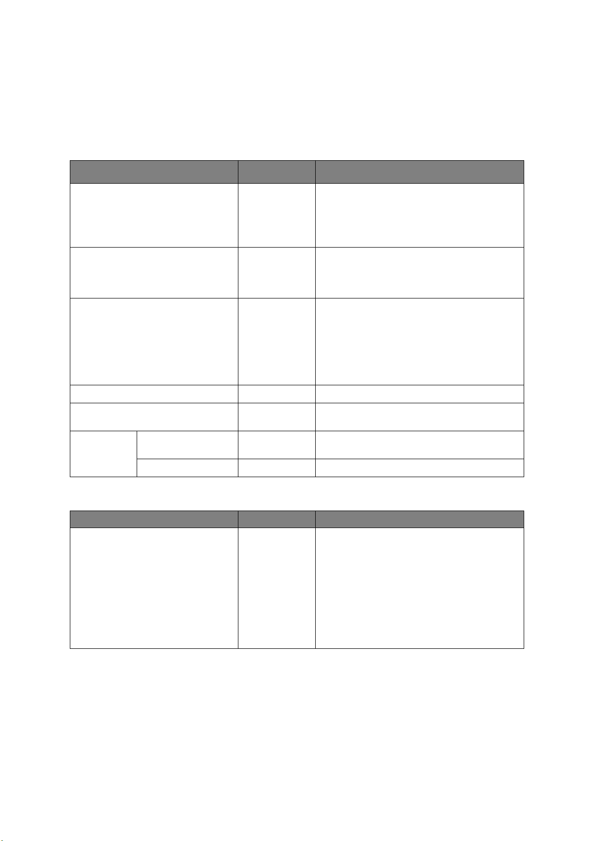
P
RINT STATISTICS
This menu should only be changed by the System Administrators. In order to gain access
to this menu, follow the instructions in “How to change the settings - admin
page 22, but hold down the MENU butt
on instead of the OK button. In this case, the
istrator” on
default password is 0000.
This menu is
in ENGLISH only.
ITEM SETTINGS EXPLANATION
ENTER PASSWORD nnnn Enters a password to enter PRINT STATISTICS
menu.
The default password is “0000.”
PRINT STATISTICS
Print Statistics function is not supported.
USAGE REPORT ENABLE/
MAINTENANCE CNT ENABLE/
RST MAIN CNT EXECUTE Resets the main counter.
RST SUPPLIES CNT EXECUTE Resets the number of replacement of
DISABLE
BLE
SA
DI
Enables/Disables the printing of the Usage
Report.
When changing a setting value, the printer is
rebooted.
Indication of frequency of consumable
exchange/non indication is set.
When Enable is set, also the maintenance
r is indicated in together.
counte
Conditions for display:
Enable must be selected in
USAGE REPORT
consumable
s.
category is not shown when
PRINT STATISTICS >
.
CHANGE
PASS
AIRP
WORD
RINT
NEW PASSWORD **** Sets a new password to enter PRINT
STATISTICS menu.
VERIFY PASSWORD **** Verifies the change
ITEM SETTINGS EXPLANATION
AirPrint ENABLE
DISABLE
Enable AirPrint function.
ENABLE
changed to Disabled by network error etc., select
Enable in this menu, network will be re-initialized,
and return to stand-by UI.
When AirPrint is enabled, DISABLE will not be
displayed. Select ENABLE in this menu, just
return to stand-by UI. Network Re-initializing will
not be executed.
There is not a menu for changing AirPrint to
disable.
is displayed only when AirPrint is
Operator panel > 49
Page 50

G
OOGLE CLOUD PRINT
ITEM SETTINGS EXPLANATION
PRINT MANUALLY Prints manually.
DELETE REGISTERED INFO Deletes the registered information.
REGISTER TO Google Cloud Print Registers to Google Cloud Print.
SETTINGS OF
oo
gle Cloud
G
Print
USING CLOUD
SERVICE
DNS PRIMARY xxx.xxx.xxx.xxx Sets the DNS server(Primary).
DNS SECONDARY
PROXY ENABLE
PROXY SERVER Sets the proxy server.
PROXY PORT NO.
PROXY USER ID Sets the proxy user ID.
PROXY PASSWORD Sets the proxy password.
ENABLE
PAUSE
DISABLE
xxx.xxx.xxx.xxx Sets the DNS server(Secondary).
DISABLE
1
~
8080
~
65535
Sets whether or not to use cloud service.
Sets whether or not to use a proxy server.
Sets the port number of the proxy server.
Operator panel > 50
Page 51
W
IRELESS SETTING
If the Wireless LAN Module is fitted.
C332dnw comes with a Wireless LAN Module as standard, but the Wireless LAN Module is
set to Disable by default. To enable the Wireless LAN Module, refer to “Wireless LAN
Module” on page 65.
ITEM SETTINGS EXPLANATION
WIRELESS
(INFRASTRUCTURE)
SETTING
WIRELESS(INFRASTRUCTURE) ENABLE
NETWORK
SETTING
WPS SETUP WPS-PBC Executes WPS-PBC.
WIRELESS
SELECTION
IP ADDRESS SET AUTO
IPV4 ADDRESS xxx.xxx.xxx.xxx Sets the IP Address.
SUBNET MASK xxx.xxx.xxx.xxx Sets the Subnet Mask.
GATEWAY
ADDRESS
DHCPV6
xxxxxx
MANUAL
SSID Input the SSID.
SETUP
SECURITY
WEP KEY Input WEP Key. 5-26 digits can be inputed.
WPA
ENCRYPTION
TYPE
WPA
PR
ESHARED
KEY
EXECUTE Wireless reconnection
DISABLE
MANUAL
xxx.xxx.xxx.xxx Sets the Gateway (default router) address.
ENABLE
DISABLE
WPS-PIN Executes WPS-PIN.
DISABLE
WEP
WPA/WPA2-PSK
WPA2-PSK
AES
TKIP/AES
Enables/disables the wireless LAN
(Infrastructure).
Select the IP address setting method.
Sets enable/disable of DHCPv6.
Lists the detected
Sets the security function of the wireless LAN.
WPA2-PSK coding method.
Input the Pre Shared Key.
wireless LAN (AP mode).
is executed.RECONNECTION
Operator panel > 51
Page 52

W
IRELESS
(AP M
ODE
) S
ETTING
If the Wireless LAN Module is fitted.
C332dnw comes with a Wireless LAN Module as standard, but the Wireless LAN Module is
set to Disable by default. To enable the Wireless LAN Module, refer to “Wireless LAN
Module” on page 65.
ITEM SETTINGS EXPLANATION
WIRELESS (AP MODE) SETTING
B
OOT MENU
WIRELESS (AP MODE) ENABLE
AUTOMATIC SETUP
(PUSHBUTTON)
MANUAL
SETUP
CONNECTION
SETTING
AP MODE USER SETTING
SSID Displays the SSID.
PASSWORD Displays the password.
SSID Input the SSID.
PASSWORD
IPV4 ADDRESS xxx.xxx.xxx.xxx Input the IP address.
DISABLE
ENABLE
DISABLE
Enables/disables the wireless LAN (AP mode).
When the OK button is pressed and the Yes/
No confirmation screen is displayed, if Yes is
selected, automatic connection can be
started with a push-button.
Input the password.
Sets whether or not to disclose the AP mode
information to users other than the
administrator.
ENABLE: Disclose user.
DISABLE: Don't disclose user.
To enter the boot menu, you should holding on the OK button as the same time as the
power is turned on.
ITEM SETTINGS EXPLANATION
ENTER PASSWORD ************ The password to enter BOOT MENU is input.
The password is same as the password to enter
ADMIN SETUP.
WIRELESS MODULE* ENABLE
DISABLE
SIDM MENU SIDM MANUAL ID# 0
~
2
~
9
SIDM MANUAL2 ID# 0
~
3
~
9
SIDM MP TRAY ID# 0
~
4
~
9
A wireless LAN module is set as enable/disable.
Even when removing a wireless LAN module after
making it enable, this menu continues enable.
* C332dnw comes with a Wireless LAN Module as
standard, but the Wireless LAN Module is set to
Disable by default. To enable the Wireless LAN
Module, refer to “Wireless LAN Module” on page 65.
Sets the Pn specified by MANUAL in the CSF
control command (ESC EM Pn) of MANUAL-1 ID
No. FX/PPR emulation.
Sets the Pn specified by MANUAL in the CSF
control command (ESC EM Pn) of MANUAL-2 ID
No. FX/PPR emulation.
Sets the Pn specified by TRAY0 (MP Tray) in the
CSF control command (ESC EM Pn) of MP Tray ID
No. FX/PPR emulation.
Operator panel > 52
Page 53

ITEM SETTINGS EXPLANATION
SIDM MENU
(cont.)
MENU LOCKOUT ENABLE
PANEL LOCKOUT MODE1
MENU
OPERATION
SETUP
SIDM TRAY1 ID# 0
SIDM TRAY2 ID#
UP/DOWN KEY
1
~
9
0
~
5
~
9
DISABLE
MODE2
OFF
NORMAL TYPE
OLD TYPE
Sets the Pn specified by TRAY1 in the CSF control
mand (ESC EM Pn) of Tray 1 ID No. FX/PPR
com
emulation.
Sets the Pn specified by TRAY2 in the CSF control
command (ESC EM Pn) of Tray 2 ID No. FX/PPR
emulation.
(If tray 2 is installed.)
Sets enable/disable of Menu Locko
ENABLE
DISABLE: It's possible to enter the menu mode.
Sets on/off Lockout function
operator panel.
MODE1: Al
Cancel and Power save button are locked out.
MODE2: All buttons except for Online and OK
button are locked out.
OFF: All buttons aren't locked out.
When choosing Category/Item/Value by the
menu mode, movement of Menu UP/DOWN
button is defined.
NORMAL TYPE:
When a Menu DOWN button is pressed, the
choices move to the next item (the way under the
indication list).
When a Menu UP button is pressed, the choices
move to the previous item (the way on the
indication list).
OLD TYPE:
When a Menu UP button is pressed, the choices
move
indication list).
When a Menu DOWN button is pressed, the
choices move to the previous item (the way on
the indication list).
: It isn't possible to enter the menu mode.
l buttons except for Online, OK,
to the next item (the way under the
ut function.
for buttons on the
Operator panel > 53
Page 54

M
AINTENANCE
R
EPLACING CONSUMABLE ITEMS
Only use genuine original consumables to ensure the best quality and
performance from your hardware. Non original products may adversely affect
your printer's performance and invalidate your warranty.
T
ONER CARTRIDGE REPLACEMENT
NOTE
When the LCD display indicates TONER LOW, or if print appears faded, first
open output tray and try tapping the cartridge a few times to evenly distribute
the toner powder. This will enable you to obtain the best “yield” from your
toner cartridge.
CAUTION!
To avoid toner wastage and possible toner sensor errors, do not
change the toner cartridge(s) until “TONER EMPTY” is displayed.
The toner used in this printer is a very fine dry powder. It is contained in four cartridges:
one each for cyan, magenta, yellow and black.
Have a sheet of paper handy so that you have somewhere
you install the new one.
Dispose of the old cartridge responsi
any regulations, recommendations, etc., which may be in force concerning waste recycling.
If you do spill any toner powder, lightly brush it off. If
cloth to remove any residue.
Do not use hot water, and never use solvents of any kind. They will make stains permanent.
bly, inside the pack that the new one came in. Follow
to place the used cartridge while
this is not enough, use a cool, damp
WARNING!
If you inhale any toner or get it in your eyes, drink a little water or
bathe your eyes liberally in cold water. Seek medical attention
immediately.
1. Press the cove
r release and open the printer’s output tray fully.
WARNING!
If the printer has been powered on, the fuser will be hot. This area
is clearly labelled. Do not touch.
Maintenance > 54
Page 55

2. Note the positions of the four cartridges. It is essential that they go back in the same
1
2
3
4
b
a
order.
1. Yellow cartridge 2. Magenta cartridge
3. Cyan cartridge 4. Black cartridge
(a) Slide the colored release collar on the cartridge to be r
right hand side of the printer.
(b) Lift the right-hand end of the cartridge and then draw the
to release the left-hand end as shown, and withdraw the toner cartridge out of
the printer.
3. Put the c
artridge down gently onto a piece of paper to prevent toner from marking
your furniture.
eplaced fully towards the
cartri
dge to the right
4. Clean the top of the ID unit with a clean, lint free cloth.
Maintenance > 55
Page 56
5. Remove the new cartridge from its box but leave its wrapping material in place for
the moment.
6. Gently shak
e the new cartridge from end to end several times to loosen and
distribute the toner evenly inside the cartridge.
7. Remove the wrapping material.
8. Holding the cartridge by its top centre, lower it into the printer ov
er the image drum
unit from which the old cartridge was removed.
9. Insert the left end of the ca
rtridge into the top of the image drum unit first, pushing
it against the spring on the drum unit, then lower the right end of the cartridge down
onto the image drum unit.
10. Pressing gent
ly down on the cartridge to ensure that it is firmly seated, slide the
colored collar fully towards the left hand side of the printer. This will lock the
cartridge into place and release toner into the image drum unit.
c
b
a
Maintenance > 56
Page 57
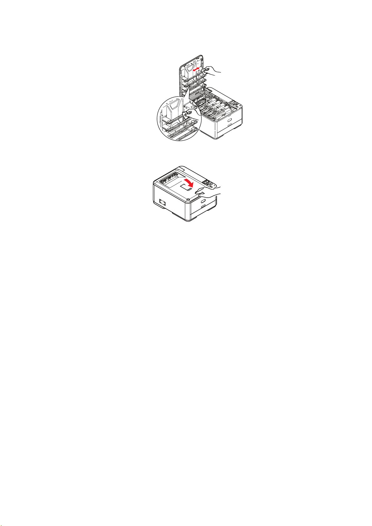
11. Gently wipe the LED head surface with a clean, lint free cloth.
12. Finally, cl
latches closed.
ose output tray and press down firmly at both sides so that the cover
Maintenance > 57
Page 58

R
EPLACING THE TRANSFER BELT UNIT
The belt unit is located under the image drum assembly.
Switch off the printer and allow the fuser to co
output tray.
1. Press the cove
r release and open the printer’s output tray fully.
ol for about 10 minutes before opening
WARNING!
If the printer has been powered on, the fuser will be hot. This area
is clearly labelled. Do not touch.
2. Holding it by its handles, lift the image drum as
cartridges, up and out of the printer.
sembly, complete with toner
3. Place the assembly in a safe place away from direc
CAUTION!
The green image drum surface at the base of each cartridge is very
delicate and light sensitive. Do not touch it and do not expose it to
normal room light for more than 5 minutes. If the drum unit needs
to be out of the printer for longer than this, please wrap the
cartridge inside a black plastic bag to keep it away from light.
Never expose the drum to direct sunlight or very bright room
lighting.
t sources of heat and light.
Maintenance > 58
Page 59

4. Pull the locking levers at each side of the transfer belt up and towards the front of
the machine.
a
5. Using the l
b
ocking levers (a), lift the belt (b) upwards and withdraw from the
a
machine.
6. Lower th
e new belt unit into place, with the drive gear towards the rear of the
printer. Locate the drive gear into the gear inside the printer by the rear right corner
of the unit, and lower the belt unit flat inside the printer.
7. Push the locking levers
towards the rear of the machine. This will secure the belt
unit in place.
8. Holding the image drum assembly by its handles, lower i
t into place in the machine,
locating the pegs at the sides into their slots in the sides of the printer cavity.
9. Finally, cl
ose output tray and press down firmly at both sides so that the cover
latches closed.
Maintenance > 59
Page 60

F
b
b
a
b
b
c
USER REPLACEMENT
The fuser is located inside the printer just behind the toner cartridges.
WARNING!
If the printer has recently been powered on, some fuser
components will be very hot. Handle the fuser with extreme care,
holding it only by its handle, which will only be mildly warm to the
touch. A warning label clearly indicates the area. If in doubt, switch
the printer off and wait at least 10 minutes for the fuser to cool
be
fore o
pening the printer cover.
1. Press the cove
2. Identify
the fuser handle (a) on the top of the fuser unit.
3. Pull the two fuser retaining levers (b) tow
r release and open the printer’s output tray fully.
ards the front of the printer so that they
are fully upright.
4. Holding the fuser by its handle (a
), lift the fuser straight up and out of the printer. If
the fuser is still warm, place it on a flat surface which will not be damaged by heat.
5. Remove the new fuser from its packaging and remove the transit material.
6. Holding the new fuser by its handle, make sure that it is the correct way round. The
reta
ining levers (b) should be fully upright, and the two locating lugs (c) should be
towards y
7. Lower the fuser into the printer, locating the two lugs (c) int
ou.
o their slots in the sides
of the printer cavity.
Maintenance > 60
Page 61

8. Push the two retaining levers (b) towards the rear of the printer to lock the fuser in
place.
b
b
9. Finally, cl
latches closed.
ose output tray and press down firmly at both sides so that the cover
Maintenance > 61
Page 62

C
LEANING
Use a clean, moist, lint-free cloth for cleaning. Do not use benzine,
thinners or alcohol as a cleaning agent.
...
THE UNIT CASING
1. Switch the printer off.
CAUTION!
2. Wipe the unit surface with
detergent.
3. Use a soft d
4. Switch the printer on.
...
THE
LED
HEAD
Clean the LED heads when printing does not come out clearly, has white lines or when text
is blurred.
There is no need to switch off the pr
1. Press the cove
2. Gently
ry cloth to dry the unit surface.
r release and open the printer’s output tray fully.
wipe the LED head surface with a clean, lint free cloth.
a soft cloth moistened sparingly with water or neutral
inter to clean the lens.
CAUTION!
Do not use methyl alcohol or other solvents on the LED head as
damage to the lens surface will occur.
3. Close output tray and press down firmly at both sides so that the cover latches
closed.
Maintenance > 62
Page 63

I
NSTALLING UPGRADES
This section explains how to install optional equipment into your printer. This includes:
> Additional pape
> Wireless LAN Module (C
A
DDITIONAL PAPER TRAY
1. Switch the printer off and disconnect the AC power cable.
2. Place additional paper tray on desired location.
3. Observing safet
the additional paper tray.
r tray
332dnw comes with a wireless LAN module as standard.)
y rules for lifting and, using locating guides, place printer on top of
Model Number: N34311A
4. Fit retaining clips as shown.
5. Re-connect the AC power cable and swit
All that remains is to adjust the printer driver to
(“Setting the driver device options” on page 64).
ch the printer ON.
make full use of the new features
Installing upgrades > 63
Page 64

S
ETTING THE DRIVER DEVICE OPTIONS
Once your new upgrade has been installed, you may need to update the printer driver so
that the additional features are available to your applications.
Accessories such as additional paper trays wi
ll only be usable if the printer driver on your
computer knows they are there.
In some cases the hardware configuration of your ma
chine is automatically detected when
the driver is installed. However, it is advisable to at least check whether all of the available
hardware features are listed in the driver.
This procedure is essential if you subsequently add extra hardware f
eatures to your
machine after the drivers have been installed and set up.
Remember that if your machine is shared between users on different computers
, the driver
must be adjusted on each user’s machine.
Windows
1. Access the driver’s Properties window.
(a) Open the Device and Printers window via the Start Menu or from the Windows
Cont
rol Panel.
(b) Right-click the icon for this machine, and choose Printer Properties from
pop-up menu.
2. Select the Device Options tab.
In
the Windows PostScript driver the tab may be calle
d Device Settings.
3. Set the options for any devices you have just installed.
the
4. Click OK to
close the window and save your changes.
Mac OS X
NOTE
Applies to the PS driver only.
1. Select System Preference from the Apple Menu. Open the Mac OS X Printers &
Scanners Preferences.
2. Ensure your
3. Click Options & Supplies.
4. Click Optio
5. Select all hardware options appropriate to your machine and click OK.
machine is selected.
ns.
Installing upgrades > 64
Page 65
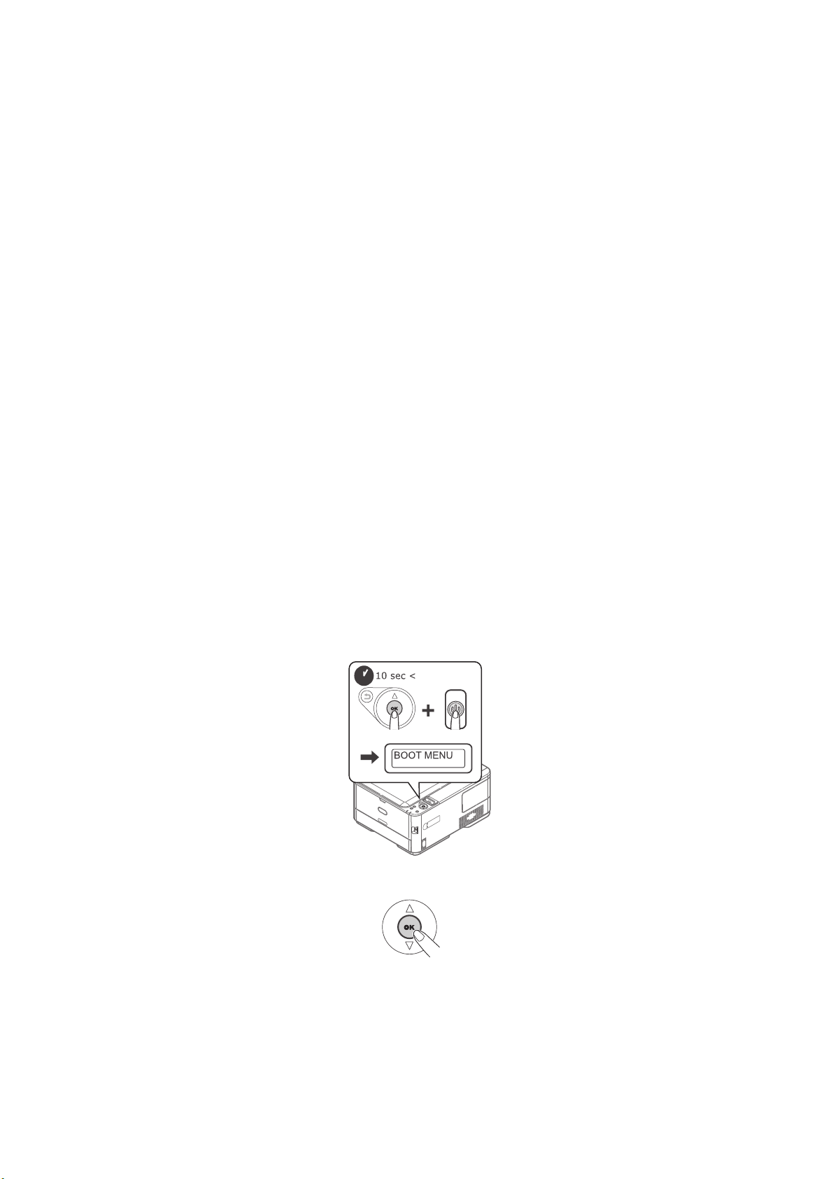
W
IRELESS
P
RECATIONS WHEN USING WIRELESS
C332dnw comes with a wireless LAN module as standard, but the wireless LAN module is
set to Disable by default. Please follow the procedure from Step 6 to enable the wireless
LAN module.
LAN M
ODULE
LAN
Carefully read the following precautions before using the machine in a wi
environment.
• In a wireless LAN environment, the machine enters sl
sleep mode.
• Do not place any devices (especially microwave ovens or digital cordle
emit weak electromagnetic waves near the machine.
• Install the machine near a wireless LAN access point
between them (the distance should be within 30m).
• Wireless connections may be difficult if there is an
reinforced concrete walls between the machine and the wireless LAN access point.
• Wireless LAN connections may have slower transmission speeds, dependi
environment, than wired LAN or USB connections. We recommend using a wired LAN or
a USB connection to print large amounts of data, such as photographs.
1. Switch off the printer.
2. Open the Wireless L
3. Connect the connector of th
4. Install the module to the printer.
5. Close the Wireless LAN I/F Cover.
6. Press and hold the OK
release it once BOOT MENU appears on the display panel.
AN I/F Cover.
e connection cable to the Wireless LAN module.
button on
the operator panel while turning on the printer, and
eep mode, but does not enter deep
or wireless device with no obstacles
y metal, aluminum framed windows, or
reless LAN
ss telephones) that
ng on the
7. Press the OK button.
Installing upgrades > 65
Page 66

8. Enter the Admin password, and then press the OK button. (The default password is
999999.)
9. Press up or do
10. Press the OK button.
11. Press the up button, sele
12. Press the ON LINE butt
C
ONNECTING VIA WIRELESS
To choose a valid default gateway.
1. Press up or down on the oper
2. Press the OK button.
3. Enter the Ad
4. Press up or down on the oper
press the OK button.
wn on the oper
ct ENABLE, and press the OK button.
on.
LAN (I
min password, and then press the OK button.
NFRASTRUCTURE MODE
ator panel to display WIRELESS MODULE.
)
ator panel to display ADMIN SETUP.
ator panel to display NETWORK SETUP, and then
5. Press up or down on the oper
GATEWAY, and then press the OK button.
6. Press down on the operator panel to displa
and then press the OK button.
ator panel to display ENABLING DEFAULT
y WIRELESS (INFRASTRUCTURE),
Connecting Using WPS
If the wireless LAN access point supports WPS, the connection to the wireless LAN can be
made easily by using the easy setup button (WPS button).
Follow the procedure below for the setup.
1. Confirm
referring to the user manual of the wireless LAN access point.
2. Confirm that
normally.
3. Turn on the printer.
When SETUP WIRELESS? app
4.
Press up or
SETTING
5. Enter the Admin password, and then press the OK button.
(The default password is 999999.)
the position of the easy setup button and when to press the button by
the wireless LAN access point has been activated and is functioning
ears,
select YES. Proceed to Step 6.
down
, and then press the OK button.
on the operator panel to display
WIRELESS(INFRASTRUCTURE)
6. Press up on the oper
ator panel to select ENABLE, and then press the OK button.
Installing upgrades > 66
Page 67

7. Press up or down on the operator panel to display WPS SETUP, and then press the
OK button.
8. Select WPS-PBC, and then press the OK button.
9. Select YES, and then press the OK button.
10. The Printer starts searching for wireless LAN access points. During 2 minutes, press
the easy setup button for the wireless LAN access point for a few seconds.
Once the setup completion screen is displayed, it indicates that the wireless LAN
setup has completed.
Set the IP Address
Set a different IP address for the wireless LAN from that of the wired LAN. Enter the setting
menu and make the settings by the following procedure.
1.
Press up or
SETTING
2. Enter the Admin password and then press the OK button.
(The default password is 999999.)
3. Press up or down on the operator panel to display NETWORK SETTING.
4. AUTO or MANUAL in the IP ADDRESS SET.
If MANUAL is selected, manually input the IPv4 Address, Subnet Mask and Gateway
Address.
down
on the operator panel to display
, and then press the OK button.
WIRELESS(INFRASTRUCTURE)
Installing upgrades > 67
Page 68

C
ONNECTING VIA WIRELESS
LAN (AP
MODE
)
Automatic Setup (Push Button)
If the wireless terminal (computer, tablet,smartphone, etc.) supports WPS-PBC (push
button), then you can use the WPS button to connect via wireless (AP mode).
Follow the procedure below to connect.
1. Confirm the position of the WPS button in the user's manual provided with the
wireless terminal (computer, tablet, smartphone, etc.).
2. Turn on the printer.
When SETUP WIRELESS? appears, select NO.
3. Press up or down on the operator panel to display WIRELESS (AP MODE)
SETTING, and then press the OK button.
4. Enter the Admin password, and then press the OK button.
(The default password is 999999.)
5. Select ENABLE, and then press the OK button.
6. Press up or down on the operator panel to display AUTOMATIC SETUP
(PUSHBUTTON), and then press the OK button.
7. Select YES, and then press the OK button.
8. Start WPS-PBC (push button) on the wireless terminal (computer, tablet,
smartphone, etc.).
Once the setup completion screen is displayed, it indicates that the wireless LAN
setup has completed.
Installing upgrades > 68
Page 69
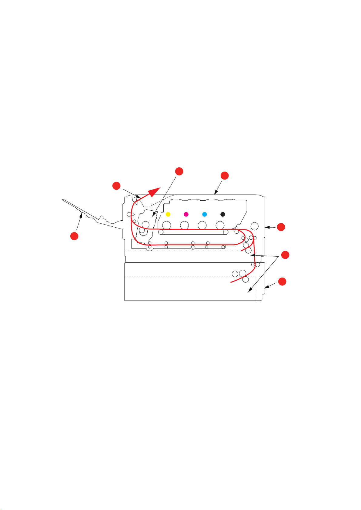
T
1
2
3
4
5
6
7
ROUBLESHOOTING
Provided that you follow the recommendations in this guide on the use of print media, and
you keep the media in good condition prior to use, y ou r pr i n te r sh o ul d g iv e ye a rs o f re l ia b le
service. However, paper jams occasionally do occur, and this section explains how to clear
them quickly and simply.
Jams can occur due to paper misfeeding from a paper tray or at
path through the printer. When a jam occurs, the printer immediately stops, and the
Attention LED on the control panel informs you of the event. If printing multiple pages (or
copies), do not assume that, having cleared an obvious sheet, others will not also be
stopped somewhere along the path. These must also be removed in order to clear the jam
fully and restore normal operation.
M
AJOR PRINTER COMPONENTS AND PAPER PATH
any point on the paper
1. Rear output tray. 5. MP tray.
2. Paper exit. 6. Paper tray.
3. Fuser unit. 7. Additional paper tray (if fitted).
4. Output tray.
Troubleshooting > 69
Page 70

P
392
381
380, 400
390
372
371
382
391
370
APER SENSOR ERROR CODES
CODE # LOCATION CODE # LOCATION
370 Duplex 390 MP tray
371 Duplex 391 Paper tray
372 Duplex 392
380 Paper feed 400 Paper size
381 Paper path 409 Rear output tray
382 Paper exit
a. If fitted.
nd
Paper tray
2
en
sor not shown)
(s
a
Troubleshooting > 70
Page 71
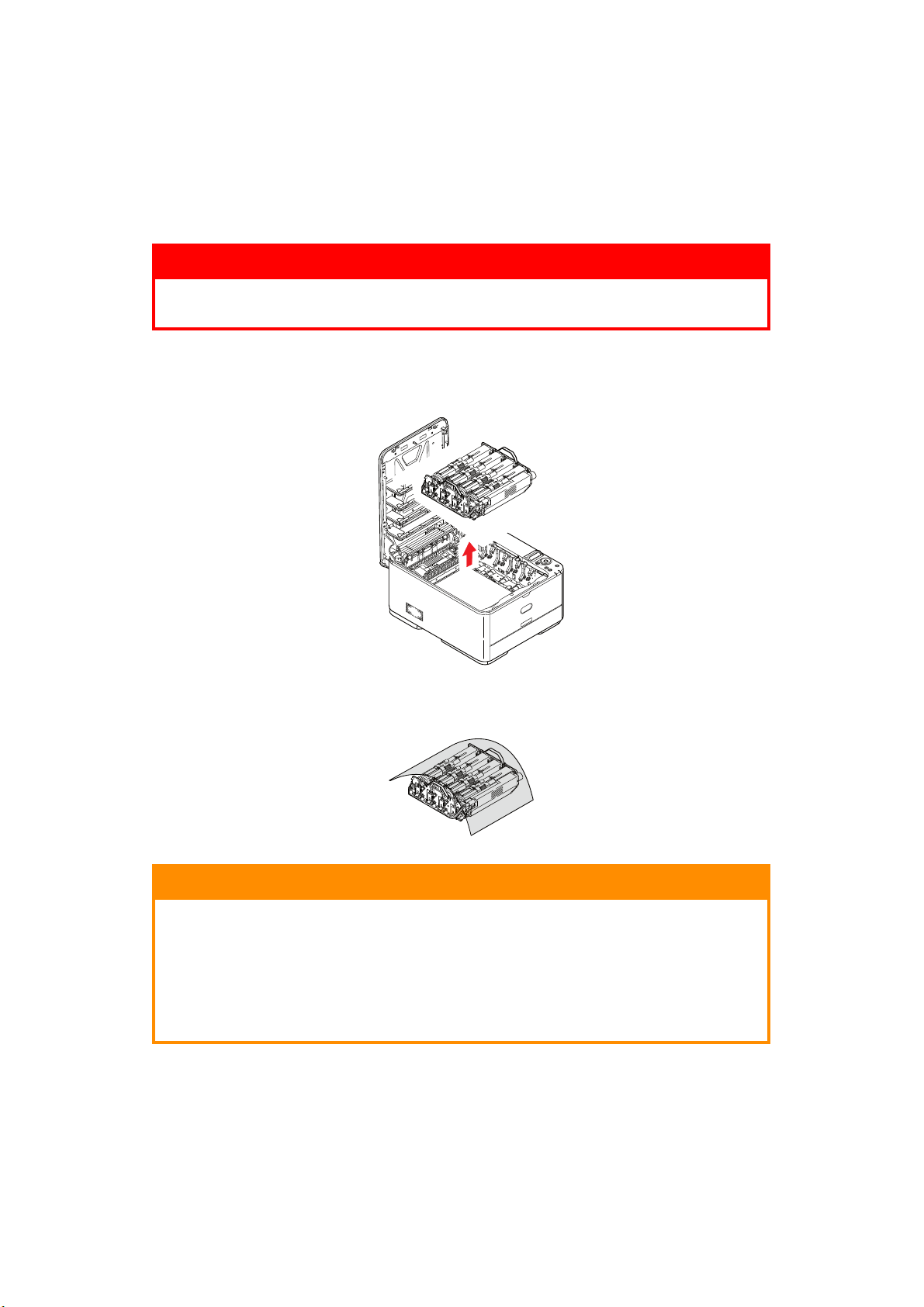
C
LEARING PAPER JAMS
1. If a sheet is well advanced out of the top of the printer, simply grip it and pull gently
to draw it fully out. If it does not remove easily, do not use excessive force. It can be
removed from the rear later.
2. Press the cove
r release and open the printer’s output tray fully.
WARNING!
If the printer has been powered on, the fuser will be hot. This area
is clearly labelled. Do not touch.
3. Holding it by its handles, lift the image drum assembly
cartridges, up and out of the printer.
, complete with the toner
Put the assembly down gently onto a piece of paper to prevent toner from marking
4.
your furniture and to avoid damaging the green drum surface, and cover.
CAUTION!
The green image drum surface at the base of the Image Drum is
very delicate and light sensitive. Do not touch it and do not expose
it to normal room light for more than 5 minutes. If the drum unit
needs to be out of the printer for longer than this, please wrap the
cartridge inside a black plastic bag to keep it away from light.
Never expose the drum to direct sunlight or very bright room
lighting.
Troubleshooting > 71
Page 72
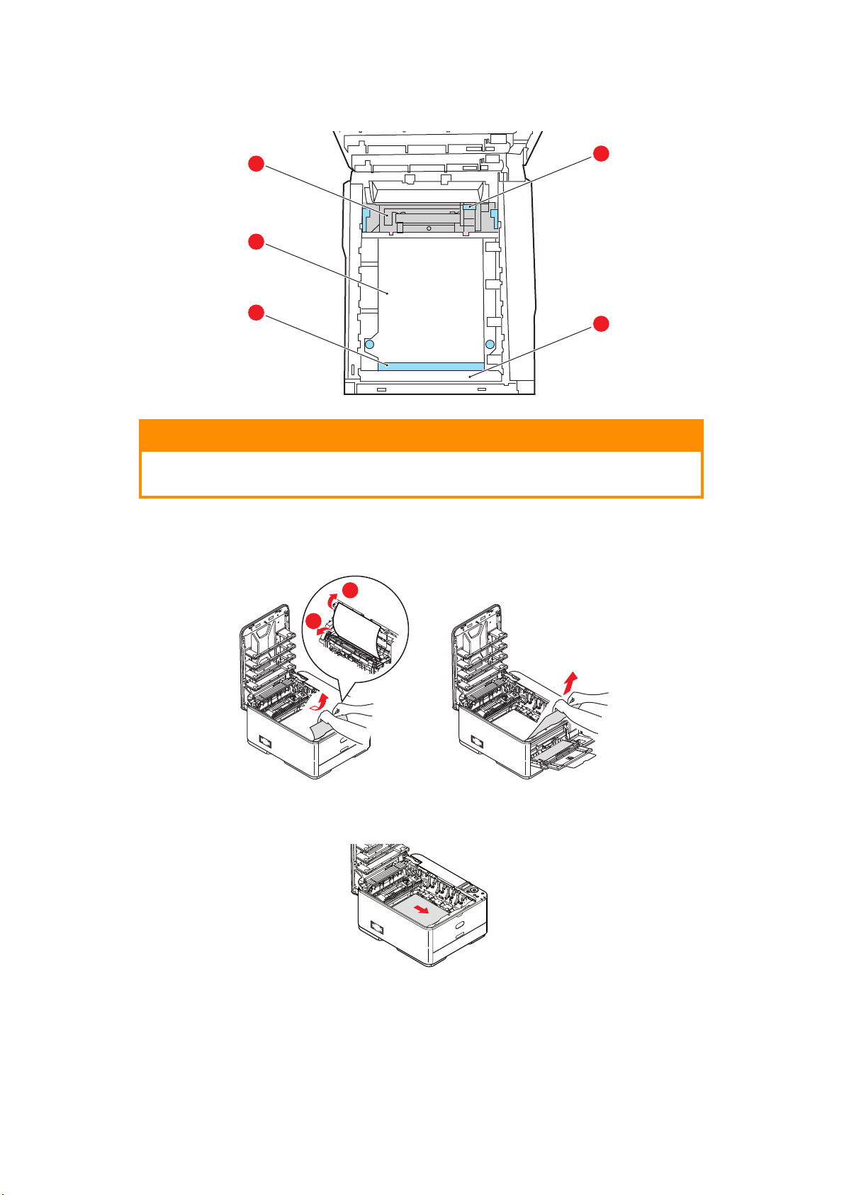
5. Look into the printer to check whether any sheets of paper are visible on any part of
d
e
c
b
a
2
1
the belt unit.
CAUTION!
Do not use any sharp or abrasive objects to separate sheets from
the belt. This may damage the belt surface.
(a) To remove a sheet with its leading edge at the front of the belt (a)
plastic guard (e) at the front of the printer, then carefully lift the sheet from the
belt and pull it forwards into the internal drum cavity and withdraw the sheet.
(b) To remove a sheet from the central area of the belt (b), carefully separate the
t from the be
shee
lt surface and withdraw the sheet.
, lift the
(c) To remove a sheet just entering the fuser (c), separate the trailing edge of the
sheet from the be
and down to rele
lt, push the fuser pressure release lever (d) towards the front
ase the fuser’s grip on the sheet, and withdraw the sheet
Troubleshooting > 72
Page 73
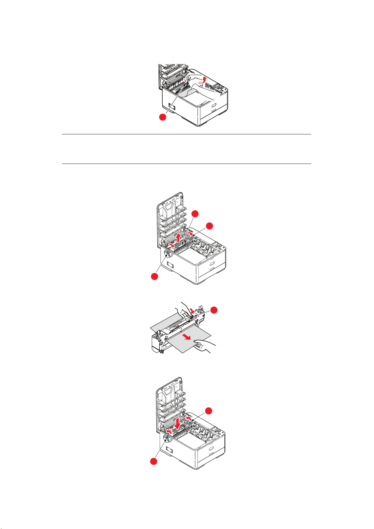
through the drum cavity area. Then allow the pressure release lever to rise
d
g
e
e
again.
NOTE
If the sheet is well advanced into the fuser (only a short length is still visible),
do not attempt to pull it back.
(d) To remove a sheet in the fuser, move t
he two ret
aining levers (e) towards the
front of the machine to release the fuser. Withdraw the fuser unit using the
handle (f).
f
e
e
(e) Press release lever (g) and pull the trapped pa
per from the fuser.
(f) Replace fuser unit into the machine and move
locking levers (e) toward the rear
of the machine.
Troubleshooting > 73
Page 74

6. If you were duplex printing when the jam occurred, check the duplex paper path:
(a) Pull the locking levers at each side of the transf
er belt up and towards the front
of the machine.
a
b
(b) Using the locking levers (a), lift the belt (b)
a
upwards and withdraw from the
machine.
(c) Look into the printer to check whether any sheets of pa
per are visible on any
part of the paper path. Pull out any sheets found in this area.
(d) Lower the belt unit into place, with the dri
ve gear towards the rear of the printer.
Locate the drive gear into the gear inside the printer by the rear right corner of
the unit, and lower the belt unit flat inside the printer.
(e) Push the locking levers towards the rear of the machine. This wi
unit in place.
7. Holding the image drum assembly by its handles, lower i
t into place in the machine,
locating the pegs at the sides into their slots in the sides of the printer cavity.
Troubleshooting > 74
ll secure the belt
Page 75

8. Lower output tray but do not press down to latch it closed yet. This will protect the
h
i
d
drum from excessive exposure to room lighting while you check the remaining areas
for jammed sheets.
9. Open rear output tra
y (h) and check for a sheet of paper in the rear path area (i).
> Pull out any sheets found in this area.
> If the sheet is low down in t
gripped by the fuser. In this case raise output tray, reach around and press down
on the fuser pressure release lever (d).
his area and difficult to remove, it is probably still
10. If you are not using the rear exit tray, close
it once any paper has been removed
from this area.
11. Pull out the paper tray
and ensure that all paper is stacked properly, is undamaged,
and that the paper guides are properly positioned against the edges of the paper
stack. When satisfied, replace the tray.
12. Finally, cl
When the jam has been cleared, if JAM RECOVERY is
ose output tray and press down firmly so that the cover latches closed.
set to ON in the SYSTEM ADJUST,
the printer will attempt to reprint any pages lost due to paper jams.
Troubleshooting > 75
Page 76

D
EALING WITH UNSATISFACTORY PRINTING
SYMPTOMS POSSIBLE CAUSES STEPS TO TAKE
Vertical white lines can
be seen on the printed
page.
Printed images are
ng ve
fadi
Printing is light. The toner cartridge is not
rtically.
The LED head is dirty. Wipe the LED head with a soft,
The toner is low. Open output tray and tap the
Foreign materials may be
pres
Light-shielding film of the
image drum cartridge is dirt
The LED head is dirty. Wipe the LED head with a soft,
The toner is low. Open output tray and tap the
The paper is not suitable for
e printe
th
properly s
The toner is low. Open output tray and tap the
the image drum.
ent in
r unit.
eated.
nt-free cloth.
li
cartridge a few ti
distribute any remaining toner. If
symptoms persist, replace the
toner cartridge.
Replace the image drum
cartridge.
Wipe the film with a soft, lint-
y.
free cloth.
lint-free cloth.
cartridge a few ti
distribute any remaining toner. If
symptoms persist, replace the
toner cartridge.
Use recommended paper.
Reinstall the toner cartridge.
cartridge a few times to evenl
distribute any remaining toner. If
symptoms persist, replace the
toner cartridge.
mes to evenl
mes to evenl
y
y
y
The paper is moist. Use paper stored in proper
The paper is not suitable for
e printe
th
Thickness and type of paper
are inappropria
Recycled paper is being used. Set one value thicker for media
Partially faded images.
ite
spots and lines
Wh
appear in solid
printing.
Vertical lines appear. The image drum cartridge is
Paper is moist or dry. Use paper stored in proper
damaged.
The toner is low. Open output tray and tap the
r unit.
te.
em
perature and humidity
t
conditions.
Use recommended paper.
Set the correct value of media
type and media weight in the
Media menu or set one value
thicker for media weight.
ei
ght in the Media menu.
w
emperature and humidity
t
conditions.
Replace the image drum
cartridge.
cartridge a few ti
distribute any remaining toner. If
symptoms persist, replace the
toner cartridge.
mes to evenl
y
Troubleshooting > 76
Page 77

SYMPTOMS POSSIBLE CAUSES STEPS TO TAKE
Horizontal Lines and
spots appear
periodically.
White area of paper is
y stained.
ghtl
li
Periphery of the letters
is smudged.
When the interval is about
94mm (4in), the image drum
(the green tube) is damaged
or dirty.
When the interval is about
30mm (1.
foreign particles in the image
drum cartridge.
When the interval is about
86mm (3.4in), the fuser unit
is damaged.
The image drum cartridge
has been exposed to light.
Paper contains static. Use paper stored in proper
Too thick paper is used. Use thinner paper.
The toner is low. Open output tray and tap the
The LED head is dirty. Wipe the LED head with a soft,
2in), there may be
Wipe it lightly wit
Replace the image drum
cartridge when it is damaged.
Open/close output tray, and print
in.
aga
Replace the fuser unit.
Re
place the image drum
cartridge if the problem is not
resolved.
temperature and humidity
conditions.
cartridge a few ti
distribute any remaining toner. If
symptoms persist, replace the
toner cartridge.
nt-free clo
li
h a soft cloth.
mes to evenl
th.
y
Toner comes off when
it is rubbed.
Glossiness is not
iform.
un
The thickness and type of the
paper are incorrectl
Recycled paper is used. Set one value thicker for media
T
he thickness and type of the
paper are incorrectly set.
y set.
Set the correct value of media
type and media weight in the
Media menu or set one value
lighter for media weight.
ei
ght in the Media menu.
w
Set the correct value of media
type and media weight in the
Media menu or set one value
lighter for media weight.
When the error message “UNKNOWN CONSUMABLE” is displayed, you can use any
consumables in your product, but you must accept the risks of using non-genuine
consumables. If the use of non-genuine consumables causes damage to the product or
results in your product not functioning to its full specification, then such damage or effect
on the product is not covered by warranty. To accept these risks and to restore function;
1. Turn off your product.
2. Press and hold the CANCEL button and tu
rn your product on.
3. After start up, release the CANCEL button.
NOTE
This operation will be recorded for future reference.
Troubleshooting > 77
Page 78

BEFORE MACHINE DISPOSAL
Before this machine is disposed of, it is recommended to erase the registered privacy data
and the stored data.
The data stored in the machine is shown below.
> Admin password
> Registered settings in various menus
> Various records
> Access control, user management data (local user, external user cache LDAP, and
Kerberos)
1. Press the button on the operator panel.
2. Press the scroll button to select ADMIN S
3. Input the admin password.
4. Select OTHERS SETUP > ERASE PRIVACY DATA.
5. Once ARE YOU SURE? is displayed, select YES, and press the OK button.
6.
Once
WOULD YOU LIKE REALLY?
Restart the machine to erase the data.
NOTE
Once the action is executed, the erased data cannot be restored. To cancel the
erasing, select NO in Step 5 or Step 6.
is displayed, select
ETUP, and press the OK button.
YES
, and press the OK button.
Before Machine Disposal > 78
Page 79

S
PECIFICATIONS
C332dn/C332dnw - N34342A , N34342B
ITEM SPECIFICATION
Dimensions 410 x 504 x 242mm (W x D x H)
Weight 21Kg approx.
Power supply N34342A: 110 to 127VAC @ 50/60 Hz ± 2%
4342B:
N3
220 to 240VAC @ 50/60 Hz ± 2%
Operating environment Operating 10 to 32 °C/20 to 80% RH
Print environment Color 17 to 27 °C @ 50 to 70% RH
opti
mum 25 °C wet, 2 °C dry)
(
Off: 0 to 43 °C/10 to 90% RH
(optimum 26.8 °C wet, 2 °C dry)
Specifications > 79
Page 80

I
NDEX
B
Belt
how to replace
.................. 58
C
Cleaning the LED head.......... 62
D
Duplex
paper size and
weight limits
................... 14
E
Envelopes
loading
.............................. 18
F
Fuser
how to replace
.................. 60
G
Getting Started .......................9
M
Major printer components and
paper path
Menu functions...................... 20
Menus
administrator menu
factory default settings..... 22
how to use........................ 20
information menu ............. 25
maintenance
menu
42, 43, 44, 45, 46, 47, 48, 49
menu map ........................ 25
print statistics menu ......... 49
system adjust menu....36, 37
Multi purpose tray
how to use
paper metrics ................... 14
.......................... 69
.......... 35
.............26, 37, 40, 41,
........................ 18
O
Operator Panel ...................... 20
P
Paper
jam clearing
jam, error codes ............... 70
loading cassette trays....... 15
loading letterhead............. 16
recommended types ......... 12
supported sheet sizes....... 13
Problem checklist
unsatisfactory printing
...................... 69
...... 76
T
Toner
how to replace
.................. 54
U
Upgrades
additional paper tray
........ 63
Index > 80
Page 81

OKI
OKI Systems (UK) Ltd.
Blays House
Wick Road
Egham
Surrey
TW20 0HJ
Tel: +44 (0) 1784 274300
Website: www.oki.com/uk
OKI Systems (Czech and Slovak), s.r.o.
Futurama Business Park Sokolovská 651/136D
186 00 Praha 8
Czech Republic
Tel: +420 224 890158
Fax:+420 22 232 6621
Website: www.oki.cz, www.oki.sk
Oki Systems (Deutschland)
GmbH
Hansaallee 187
40549 Düsseldorf
Tel: +49 (0) 211 / 5266-0
Fax: +49 (0) 211 59 33 45
Website: www.oki.de
Email: info@oki.de
CEE Export Group:
OKI Systems (Poland) Sp. z o.o.
Platinum Business Park 2, 3rd Floor
ul. Domaniewska 42, 02-672 Warsaw
Poland
Tel: +48 (0) 22 448 65 00
Fax: +48 (0) 22 448 65 0
Website: www.oki.pl
Albania, Bosnia, Bulgaria, Croatia,
Cyprus, Estonia, Greece, Israel,
Latvia, Lithuania, Macedonia,
Romania, Serbia, Slovenia
Oki Systèmes (France) S.A.
Zone Silic - Immeuble Osaka
21 rue du Jura
CS 90277
94633 RUNGIS Cedex
FRANCE
Tél: Standard 0820 200 410
Hotline 01 76 54 21 50 (n° non
surtaxé)
Website: www.oki.fr
OKI Systems (Italia) S.p.A.
via Milano, 11,
20084 Lacchiarella (MI) Italy
Tel: +39 (0) 2 900261
Website: www.oki.it
OKI Systems (Polska) Sp. z o.o
Platinium Business Park II, 3rd
Floor
ul. Domaniewska 42
02-672 Warsaw
Poland
Tel: +48 22 448 65 00
Fax: +48 22 448 65 01
Website: www.oki.pl
E-mail: oki@oki.com.pl
Hotline: 0800 120066
E-mail: tech@oki.com.pl
OKI Europe Limited, Sucursal
em Portugal
Av. Quinta Grande, nº 53
7º D - Alfragide
2610-156 Amadora
Portugal
Tel: +351 21 470 4200
Fax: +351 21 470 4201
Website: www.oki.com/pt
E-mail: oki-portugal@okieurope.com
Oki Service
Serviço de Apoio Técnico ao
Cliente
Tel: 214 727 660
E-mail: portugal@okiservice.com
OKI Systems Rus, LLC (Russia)
Sector B, 3rd Floor, Svyatogor-4
Business Center10/4, Letnikovskaya
str.115114, Moscow
Tel: +7 495 258 6065
Fax: +7 495 258 6070
e-mail: info@oki.ru
Website: www.oki.ru
Technical support:
Tel: +7 495 564 8421
e-mail: tech@oki.ru
Oki Systems (Belgium)
Medialaan 24
1800 Vilvoorde
Helpdesk: 02-2574620
Fax: 02 2531848
Website: www.oki.be
OKI Systems (Danmark) a·s
Herstedoestervej 27
2620 Albertslund
Danmark
Adm.: +45 43 666 500
Fax: +45 43 666 590
E-mail: salg@oki.dk
Website: www.oki.dk
OKI Europe Ltd. (Branch)
Building 7W A
Dubai Airport Free Zone
PO Box 54604
Dubai, UAE
Tel: +971 4 204 5810
Website: www.oki.com/me
Oki Systems (Sweden) AB
Box 1193
164 26 KISTA
Stockholm
Sverige
Tel: +46 (0) 8 634 37 00
Fax: +46 (0) 8 634 37 01
Website: www.oki.se
Oki Systems (Schweiz)
Baslerstrasse 15
CH-4310 Rheinfelden
Support deutsch +41 61 827 94 81
Support français +41 61 827 94 82
Support italiano +41 61 827 94 73
Tel: +41 61 827 94 94
Email: info@oki.ch
Website: www.oki.ch
Oki Data Americas Inc.(United
8505 Freeport Pkwy
Suite 600
Irving, TX 75063
http://www.oki.com/us/printing
Oki Data Americas Inc.(Canada
5800 Hurontario Street Suite 1020
Mississauga, ON L5R 4B9
Tél: 1-905-608-5000
Téléc: 1-905-608-5040
http://www.oki.com/ca
Oki Data Americas Inc.(América
Latina (OTRO))
8505 Freeport Pkwy
Suite 600
Irving, TX 75063
Tel (Español): 1-856-222-7496
1-856-222-5276
Fax: 1-856-222-5260
Email: LASatisfaction@okidata.com
Oki Data de Mexico, S.A. de C.V.
Mariano Escobedo #748, Piso 8
Col. Nueva Anzures
C.P. 11590, México, D.F.
Tel: 52-555-263-8780
Fax: 52-555-250-3501
http://www.oki.com/mx
CONTACT DETAILS
Oki contact details > 81
Page 82

Ltda.
Av. Alfredo Egídio de Souza Aranha,
100 - 5º Andar - Bloco C
Chácara Santo Antonio - São Paulo,
SP - Brasil
CEP: 04726-170
Tel: 55-11-3543-5500
Fax: 55-11-3444-3501
email: okidata@okidata.com.br
http://www.oki.com/br
Argentina/Chile/Paraguay/Perú/
Uruguay
Oki Data Americas, Inc.
Sucursal Argentina
Ugarte 3610 Piso 4°(1605) Olivos
Buenos Aires, Argentina
TEL: +54 11 5288 7500
Fax: +54 11 5288 7599
Colombia/Ecuador/Venezuela/
Centroamérica y Caribe
Oki Data Americas, Inc.
Sucursal Colombia
!"$%&'!!!
Bogotá Colombia
TEL: +57 1 704 5159
Oki Data (Singapore) Pte. Ltd.
438A Alexandra Road #02-11/12,
Lobby 3, Alexandra Technopark
Singapore(119967)
Tel: (65) 6221 3722
Fax: (65) 6594 0609
http://www.oki.com/sg/printing
Oki Systems (Thailand) Ltd.
1168/32 Lumpini Tower,
16th Floor, Rama IV Road,
Tungmahamek, Sathorn
Bangkok 10120
Tel: (662) 679 9235
Fax: (662) 679 9243/245
http://www.oki.com/th/printing
Oki Data(Australia) Pty Ltd.
Level1 67 Epping Road, Macquarie
Park
NSW 2113, Australia
Tel: +61 2 8071 0000
(Customer Support Tel: 1800 807 472)
Fax: +61 2 8071 0010
http://www.oki.com.au
OKI Data New Zealand
8 Antares Place Rosedale,
Auckland, 0632 New Zealand
Tel: (64) 9 477 0500
(Customer Support: 0800 778 800)
Fax: (64) 9 477 0549
http://www.oki.co.nz
!"#$%&
Suite 21.03, 21st Floor Menara IGB,
Mid Valley City,
Lingkaran Syed Pura 59200,
Kuala Lumpur, Malaysia
Tel: (60) 3 2287 1177
Fax: (60) 3 2287 1166
Oki contact details > 82
Page 83

4-11-22 Shibaura, Minato-ku,Tokyo
108-8551, Japan
www.oki.com/printing/
January 2018
46472902EE Rev4
 Loading...