

Page 1
Application Note AN1001
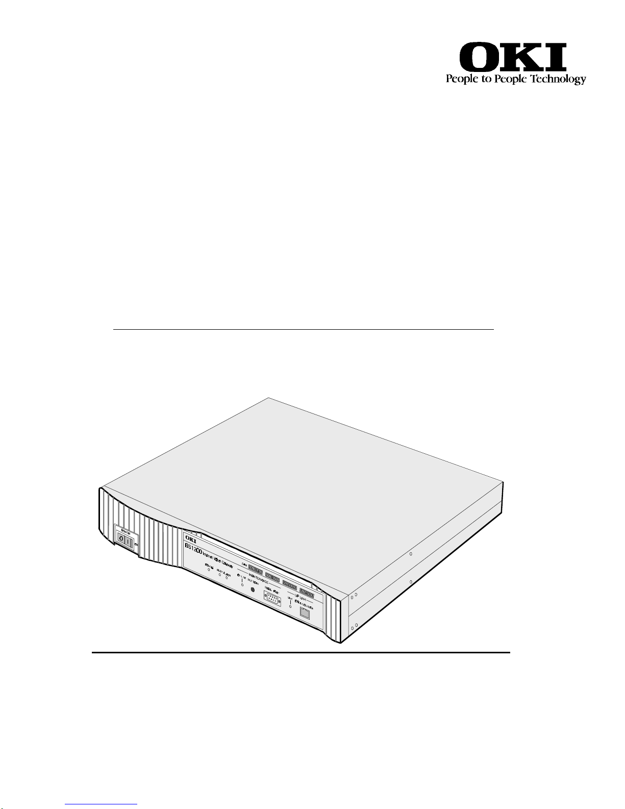
BS1200
Internet Voice
Gateway
THE BS1200 AND NETWORK ACCESS
SECURITY
Oki Electric Industry Co., Ltd.
Page 2

2
Page 3

BS1200 and Network Access Security. A Basic Network Primer
3
Introduction:
This paper is a brief explanation of some of the many possibilities of installing the BS1200 IVG within the
constraints of Network Access Security (NAS) Solutions that your client(s) may have implemented. It does
not attempt to explain all the deeper technical details behind the technologies involved. However it will
show you the most common forms of NAS and the best recommended solutions for them. Let us begin with
the basics.
What is a Network?
In it’s most basic form a network is nothing more than two or more computer systems sharing basic
resources. (See fig 1) In this example we have a printer connected through a simple cable arrangement port
to port. Parallel port and parallel port to a switch box to share the printer.
A SIMPLE NETWORK
fig 1
The next step up in complexity is a peer to peer based network. (see fig 2) This is a network comprised
typically of several computers linked together by a cable scheme and a communications protocol. The cable
scheme links all the computers together as a common group. The communications protocol allows all the
computers to talk together (exchange data) in a common language.
A peer to peer network has several advantages over a simple resource (appliance) sharing network. The
network users not only share resources in a more efficient manner they gain the advantage of exchanging
files without removable media (floppy disks). They can also share a modem (fewer phone lines), exchange
email, print from designated computers thereby needing fewer printers around the workplace, and overall,
working together in an enriched and improved workplace environment.
Peer to Peer Network
SHARED
FAX
APPLICATION
FILES
MODEM
INTERNET
DATABASE
PRINTER
MCS v4.0 Firmware v2.0
fig 2
ETHERNET HUB
Page 4

BS1200 and Network Access Security. A Basic Network Primer
4
The next step up is to a network type called Server or Host based networking (see fig 3). Here is where
things can get really complicated. First a few definitions:
A server is a dedicated computer for storing Applications and Data files in a central location. (Windows
NT, Novell Server, Unix, and Linux are some examples of server based systems). A server can also be a
computer connected to a network supplying dedicated services to the network (Print services, Fax services,
Email services, Identification services, and many others). The key words here are dedicated and services.
A Host is typically associated with BIG IRON, i.e.: Main Frames and Mini Computers. IBM, HP, DEC,
Tandem and others are well known for Host based solutions. Host based systems are designed around the
idea that the central computer or system does all the thinking (computing) and storing of Applications and
Data Files (Hosting) for the entire network. Although this is changing rapidly due to increased computing
power on the desktop.
SERVER BASED NETWORK
ROUTER
SECURE NETWORK SEGMENTS
SWITCH
SERVER
&
DISK ARRAY
HUB
INTERNET
SWITCH
FIREWALL
SERVER
UNSECURED NETWORK SEGMENT
SERVER
HUB
HUB
SERVER
FIG 3
Server and Host based network systems are almost always associated with companies, corporations,
governments, educational organizations (schools and universities), and other, larger, more structured
environments than a simple or peer-to-peer network could service. Although with the increased computing
power on the desktop, server based networks are now cost effective in smaller and smaller environments.
The needs of these larger organizations add tremendous complexity to network requirements.
Interdepartmental data sharing, email, faxing, live video transmissions, and now voice communications, are
going out over the network. All of this traffic (packet transmissions) is increasing by exponential amounts
almost daily.
Although there are several network protocols in existence today for the purposes of this paper we will
concentrate on the protocol named TCP/IP over Ethernet. TCP is an acronym for Transport Control
Protocol. The IP part stands for Internet protocol. This protocol duo is commonly known as packet
communications. This is an identification and delivery method for data packets traversing a network.
Packets are little packages of data with an address destination imbedded within. TCP/IP can be likened to a
postal service with addresses identifying unique residences for delivery of data. Ethernet is a hardware
solution to tie everything together. The Roadways of data packets, i.e.: Roads (the wires), interchanges and
junctions (hubs, routers, and switches) speed limits (Bandwidth), all these and more are hardware related.
Stop signs (NAS), Yield signs (prioritizing whose data is delivered first), these and others are software
related. However they are all tied together by the standard called TCP/IP over Ethernet.
MCS v4.0 Firmware v2.0
Page 5

BS1200 and Network Access Security. A Basic Network Primer
5
Because of this standard hundreds of millions of people worldwide are able to use data linked by networks
without ever knowing it. And the biggest network of them all is the Internet. Imagine yourself getting into
your favorite vehicle. Starting the engine and heading out onto that great and wondrous open road. The
whole wide world is waiting for you to drive by. Highway after byway just waiting for you with exciting
adventures. Little towns and big cities for you to drive through and explore. People to meet and talk with
Shops and malls and banks and factories waiting for you to go exploring. But as we all know not everyone
is to be trusted. And that is why we have police, security guards, locked doors and all manner of access
security. Well the Internet is no different.
There is a group of network services known as Network Access Security or NAS.
What is Network Access Security?
NAS is an electronic equivalent to police, security guards, and locked doors.
There are three main types of NAS that can impede the implementation of the BS1200 VoIP Gateway.
They are Firewalls, Proxy servers, and Network Address Translation (NAT) Routers.
When implementing a BS1200 in a situation involving one of these NAS solutions you must be aware of
certain requirements for each type of installation.
A NAS solution is designed to keep unwanted visitors away from areas of a network that are not open to
the public. Just as there are places in society that must be guarded from ignorant or malicious tampering or
outright theft, Network administrators must do the same with their data. All NAS solutions are designed,
like a guard at the entrance to a building to keep out unwanted visitors. They all have their own way of
accomplishing this, the explanation of how this done is far too technical for our purposes here, but they all
introduce a common set of obstacles to the smooth and flawless installation and operation of the BS1200.
We will explain the specifics for each situation as we go along.
The three main things to consider for a NAS situation are Delay, non static IP addressing, and lack of Open
communications ports.
1). DELAY: One of the main obstacles for the BS1200 is Delay in packet delivery. All NAS solutions
introduce delay in packet delivery. A NAS must verify each packet being delivered within its’ security
zone. The introduction of this delay can cause unacceptable voice degradation into the VoIP stream.
2). NEED FOR A STATIC IP ADDRESS: In order for a BS1200 to receive a stream of data packets from
another BS1200 there must be a static IP Address leading to it. That is, during the setup process (MCS) an
IP Address is assigned to each unit on the network. If the IP Address is changed by a NAS then the call
cannot get through.
3). OPEN COMMUNICATION PORTS: One of the more technical areas of TCP/IP over Ethernet is
called packet type identification. For each packet type there is a port assignment for it. (See Table 1)
Item
No.
1 Q.931 1720 TCP
2 H.245 1721,1722,1723, 1724 TCP
3 RAS 1718, 1719 UDP
4 RTP/RTCP 5004 ~ 5011 UDP
5 TELNET, FTP, DNS 23,21,53 TCP
Type of
Communication
Port No. TCP/UDP
Table 1
MCS v4.0 Firmware v2.0
Page 6

BS1200 and Network Access Security. A Basic Network Primer
6
First a Firewall Situation:
A firewall can be described as a filter or guard at the gate. They are setup to allow only certain kinds of
incoming data packets, permissible outside requests for information from inside the firewall, returning
information requested from inside the firewall. If an incoming data packet does not have permission to go
through it is rejected. This filtering process adds delay to the data streams. Delay is always a consideration
for a BS1200 installation. A firewall does not change the IP addresses of the devices inside its zone. All IP
addresses remain public and static
It is generally preferable that a BS1200 network installation be connected to the IP network outside of any
existing firewall installation. (See fig 4) When for practical or policy reasons, an installation must be
routed through a firewall some performance degradation may occur. (See fig 4a)
If possible the BS1200 should be installed according to fig 4. This places the BS1200 IVG in the public IP
address zone. The advantages to this are the elimination of added delay due to the firewall, maintaining a
static public IP address, and less systems administration with communication port assignments on the
firewall. The only thing that may be needed for the client to implement is another hub in front of the
firewall and maybe some table listings on the Router.
INTERNET
ROUTER
EXTERNAL
IP ADDRESS
NNN.NNN.NNN.NNN
(PUBLIC)
FIREWALL
SERVER
(STATIC PUBLIC IP ADDRESS)
INTERNAL
IP ADDRESS
NNN.NNN.NNN.NNN
(PUBLIC)
HUBHUB
LAN
BS1200
PHONE LINKS
PBX OR KTS OR
ANALOG PHONES
OUTSIDE A FIREWALL ZONE EXAMPLE
fig 4
Figure 4 is the preferred installation method for the BS1200 with a firewall.
In figure 4a the addition of a switch or connection to an existing switch just after the firewall and making
sure the proper ports for voice and fax packets are open for use. (See table 1)Figure 4a is the preferred
installation method for the BS1200 after a firewall.
LAN
STATIC IP ADDRESS
(PUBLIC)
BS1200
PHONE LINKS
PBX OR KTS OR
ANALOG PHONES
ROUTER
INTERNET
INSIDE A FIREWALL ZONE EXAMPLE
EXTERNAL
IP ADDRESS
NNN.NNN.NNN.NNN
(PUBLIC)
FIREWALL
SERVER
INTERNAL
IP ADDRESS
NNN.NNN.NNN.NNN
(PUBLIC)
OPEN PORTS
Reference
TABLE 1
SWITCH
You should also be aware that, as in the above example, when a BS1200 IVG is routed through a firewall
the Router IP address no longer serves as the BS1200 Gateway address. Instead, the internal IP address of
the firewall becomes the Gateway address to be associated with the BS1200 IVG.
MCS v4.0 Firmware v2.0
fig 4a
Page 7

BS1200 and Network Access Security. A Basic Network Primer
7
Reminder: When installing the BS1200 network within a firewall, voice and fax packets must be routed
through specified firewall ports using the information in table 1. (See table 1)
Second a Proxy Server Situation:
A Proxy Server can be described as a filter or guard at the gate with a Network Address Translation (NAT)
or diplomat go between function added. Proxy Servers are setup to allow only certain kinds of incoming
data packets, permissible outside requests for information from inside the Proxy Server zone, returning
information requested from inside the Proxy Server zone. If an incoming data packet does not have
permission to go through it is rejected. If the data packet is accepted the diplomat takes over. The diplomat
function is to hide the true IP addresses of the outside world and the Ip addresses of the inside world from
each other. For example, the NAT function takes a permitted incoming data request from John to the
recipient Steve and says hello Steve I have a message from David (John). Steve processes the request and
sends it back with the diplomat who then sends to John the response from Hector (Steve). This dual
process adds delay to the data streams. Delay is always a consideration for a BS1200 installation. A Proxy
Server also changes the IP addresses of the devices inside its zone. All IP addresses also remain private to
the outside world. Private IP addresses and non-static IP addresses are other considerations for a BS1200
installation.
To work around these conditions the following recommendations should be implemented.
First, if the clients Proxy Server allows for it, an additional Network Interface Card (NIC) should be added
and set up to channel a public data path, commonly known as the Demilitarized Zone or DMZ. (See fig 5a)
This creates a public path to the BS1200 and does not interfere with the Network security policies already
in place. This also eliminates the Filter/NAT security delays improving BS1200 performance.
INTERNET
ROUTER
A PROXY SERVER EXAMPLE
ADDING A NIC FOR DMZ ZONE
fig 5a
NIC IN NIC OUT
EXTERNAL
IP ADDRESS
NNN.NNN.NNN.NNN
(PUBLIC)
PROXY
SERVER
NIC DMZ
INTERNAL
IP ADDRESS
XXX.XXX.XXX.XXX
(PRIVATE)
(PUBLIC)
HUB
LAN
BS1200
PHONE LINKS
PBX OR KTS OR
ANALOG PHONES
Figure 5a is the preferred installation method for the BS1200 through a Proxy Server.
If for some reason the existing equipment or client policy does not allow for the addition of a NIC then
connecting the BS1200 outside of the Proxy Server zone is the recommended solution. (See fig 5b)
Locate a free port on an existing switch, or if one does not already exist the addition of a switch, to the
outside of the Proxy Server zone. This configuration maintains the BS1200 in the public zone thereby
keeping a static IP address.
MCS v4.0 Firmware v2.0
Page 8

BS1200 and Network Access Security. A Basic Network Primer
8
INTERNET
DMZ
ROUTER
SWITCH
NIC IN NIC OUT
EXTERNAL
IP ADDRESS
NNN.NNN.NNN.NNN
(PUBLIC)
A PROXY SERVER EXAMPLE
PROXY
SERVER
IP ADDRESS
XXX.XXX.XXX.XXX
INTERNAL
(PRIVATE)
(PUBLIC)
HUB
LAN
BS1200
PHONE LINKS
PBX OR KTS OR
ANALOG PHONES
ADDING A SWITCH BEFORE THE PROXY SERVER
fig 5b
Third a Network Address Translation (NAT) Router Situation:
As the name implies a NAT Router translates network addresses, like a Proxy server does. A NAT
however lacks the higher end capabilities a SERVER has. You should already be somewhat familiar with
what a NAT Router does from the previous Proxy server solution. Consider a NAT Router the smaller
cousin to a Proxy Server.
To install a BS1200 behind a NAT Router (See fig 6a) you must first check with the client on their
policies and procedures regarding the level of security they require. If allowable then disable the NAT
function on the Router, if the Router has only one port.
BS1200
PHONE LINKS
PORT 0
WITH NAT TURNED OFF
HUB
PBX OR KTS OR
ANALOG PHONES
INTERNET
EXTERNAL
IP ADDRESS
NNN.NNN.NNN.NNN
(PUBLIC)
NAT ROUTER
A NAT ROUTER EXAMPLE
INTERNAL
IP ADDRESS
NNN.NNN.NNN.NNN
(PUBLIC)
LAN
NAT TURNED OFF
fig 6a
If the Router has more than one port, (See fig 6b), and if the equipment allows for it, then turn the NAT
function off for that port and then connect the BS1200 to that port.
INTERNET
EXTERNAL
IP ADDRESS
NNN.NNN.NNN.NNN
(PUBLIC)
NAT ROUTER
A NAT ROUTER EXAMPLE
ADD / USE A SECOND PORT
PORT 1
WITH NAT TURNED OFF
PORT 0
WITH NAT TURNED ON
INTERNAL
IP ADDRESS
XXX.XXX.XXX.XXX
(PRIVATE)
(PUBLIC)
HUB
LAN
BS1200
PHONE LINKS
PBX OR KTS OR
ANALOG PHONES
MCS v4.0 Firmware v2.0
fig 6b
Page 9

BS1200 and Network Access Security. A Basic Network Primer
9
Should the client require that a security solution remain in place then (See figs 6c & 6d) the
recommendation is to put a Firewall in place and follow the same procedure as the previous examples for a
Before and After a Firewall solution.
INTERNET
EXTERNAL
IP ADDRESS
NNN.NNN.NNN.NNN
(PUBLIC)
A NAT ROUTER EXAMPLE
(INSTALL A FIREWALL SERVER)
A BS1200 AFTER THE FIREWALL
NAT ROUTER
INTERNET
EXTERNAL
IP ADDRESS
NNN.NNN.NNN.NNN
(PUBLIC)
A NAT ROUTER EXAMPLE
(INSTALL A FIREWALL SERVER)
A BS1200 BEFORE THE FIREWALL
NAT ROUTER
PORT 0
WITH NAT
TURNED OFF
PORT 0
WITH NAT
TURNED OFF
HUB
ADD A
FIREWALL
fig 6c
ADD A
FIREWALL
fig 6d
OPEN PORTS
Reference
TABLE 1
(STATIC PUBLIC IP ADDRESS)
SWITCH
INTERNAL
IP ADDRESS
NNN.NNN.NNN.NNN
(PUBLIC)
LAN
(PUBLIC)
HUB
INTERNAL
IP ADDRESS
NNN.NNN.NNN.NNN
(PUBLIC)
LAN
BS1200
BS1200
PHONE LINKS
PBX OR KTS OR
ANALOG PHONES
PHONE LINKS
PBX OR KTS OR
ANALOG PHONES
Conclusion:
As you have seen the installation of the BS1200 VoIP Gateway into most existing Networks is fairly
simple if you remember just a few basic considerations.
1). Minimize delay whenever possible.
2). Always keep the BS1200 in a Static Public IP Address Zone.
3). Make sure the correct communications ports are available whenever required.
MCS v4.0 Firmware v2.0
Page 10

BS1200 and Network Access Security. A Basic Network Primer
10
MCS v4.0 Firmware v2.0
 Loading...